switching and control professionals -...
TRANSCRIPT
Selection table switching relays, control relays and coupling relays C0Switching relay ER12DX C1Switching relay ER12 C2Impulse switch with integrated relay function ESR12NP C3Multifunction impulse switch with integrated relay function ESR12M C4Switching, control and coupling relays ER12 C5Switching relays and control relays ER12 and coupling relays KR09 C6Switching relay ER61 and Impulse switch with integrated relay function ESR61NP C7Switching relay ER61 and Multifunction impulse switch with integrated relay function ESR61M C8Isolating relay ETR61NP with window contact FK C9Technical data C10
Switc
hin
g a
nd
co
ntr
ol
pro
fess
ion
als
Switching on the future.
Electronic switching relays,control relays and coupling relays
C

Switching and control professionalsProfessional hybrid relays combine the advantages of nonwearing electronic control with high switching capacity of special relays. We also use mainly bistable relays. Thus preventing coil power loss even in the on mode. This increases energy effi ciency and reduces heating in the switch cabinet.
1) Glow lamp current independent from the ignition voltage. 2) Depends on the set function. 3) If the control voltage is 230 V, but the phase conductor is different from the 230 V supply voltage, the universal voltage control input must be used. 4) At the control input . 5) The relay contact can be open or closed when putting into operation. It will be synchronised at first operation. 6) The switched consumer may not be connected to the mains before the short automatic synchronisation after installation has terminated. 7) Duplex technology: When switching 230V/50Hz the contact switching takes place in the zero passage when L is connected to 1(L) and N to (N). The standby loss is then 0.1 Watt.
Selection table switching relays, control relays and coupling relays
C0
Page C1 C2 C2 C3 C4 C5 C5 C5 C6 C6 C7 C7 C8 C8 C9pi
ctog
ram
s
ER12
DX-
UC
ER12
-200
-8..2
30V
UC
ER12
-110
-8..2
30V
UC
ESR1
2N
P-8.
.230
V UC
ESR1
2M-8
..230
V UC
ER12
-001
-230
V
ER12
-002
-230
V
ER12
-001
-8..2
30V
UC
ER12
-002
-8..2
30V
UC
KR09
-12
V UC
, 24
V UC
, 230
V
ER61
-8..2
30V
UC
ESR6
1NP-
8..2
30V
UC
ER61
-230
V
ESR6
1M-8
..230
V UC
ETR6
1NP-
230
V
Modular device for mounting on DIN rail EN 50022, number of modules 18 mm each
1 1 1 1 1 1 1 1 1 ½
Built-in device for installation (e.g.fl ush-mounting box) and surface mounting
Number NO contacts or changeover contact (W) potential free (not potential free)
1 2 1 (1)1+1 2)
2 2) 1W 2W 1W 2W 1 1W (1) 1W1+1
2)
2 2) (1)
Number NC contacts potential free 1 1-22) 1 1-22)
Zero passage switching 7)
Switching capacity 16A/250V AC
Switching capacity 10A/250V AC 6A
Incandescent lamp load W 2000 2000 2000 2300 2000 2300 2000 2000 2000 500 2000 2000 2300 2000 2000
Bistable relay(s) as relay contact(s) 5) 5) 5) 6) 5) 5) 5) 6) 5)
Switchable between the functions forimpulse switches and switching relays
Universal control voltage
Additional control voltage 230 V
Supply voltage same as control voltage
Supply voltage 230 V 3)
No standby loss
Low standby loss
Glow lamp current (mA)at the control input 230 V 150 1) 50 1)4)

1 NO contact potential free 16A/250V AC, incandescent lamp load up to 2000W. No standby loss.Modular device for DIN-EN 50 022 rail mounting.1 module = 18 mm wide, 58 mm deep.
State-of-the-art hybrid technology combines advantages of nonwearing electronic control withhigh capacity of special relays.
* With the Eltako Duplex technology the normally potential-free contacts can still switch in zero passage when switching 230V AC 50Hz and therefore drastically reduce wear. Simply connect the neutral conductor to the terminal (N) and L to 1 (L) for this. This gives an additional standby consumption of only 0.1 Watt.If the contact is used for controlling switching devices which do not perform zero passage switching themselves, (N) should not be connected because the additional closing delay otherwise causes the opposite effect.
Universal control voltage 8 to 230 V UC.
Very low switching noise.
Contact position indicator with LED.
Same terminal connection as electromechanical switching relay R12-100-.
By using a bistable relay coil power loss and heating is avoided even in the on mode. The relay contact can be open or closed when putting into operation. It will be synchronised at first operation.
.
ER12DX-UC *
Switching relay ER12DX
C1
Technical data page C10.
ER12DX-UC 1 NO 16A EAN 4010312 205402
Recommended retail prices excluding VAT.
Typical connection
If N is connected, the zero passage switching is active.
C2
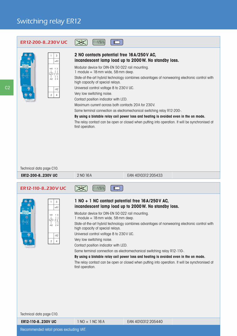
Switching relay ER12
2 NO contacts potential free 16A/250V AC, incandescent lamp load up to 2000W. No standby loss.Modular device for DIN-EN 50 022 rail mounting.1 module = 18 mm wide, 58 mm deep.
State-of-the-art hybrid technology combines advantages of nonwearing electronic control withhigh capacity of special relays.
Universal control voltage 8 to 230 V UC.
Very low switching noise.
Contact position indicator with LED.
Maximum current across both contacts 20A for 230V.
Same terminal connection as electromechanical switching relay R12-200-.
By using a bistable relay coil power loss and heating is avoided even in the on mode.The relay contact can be open or closed when putting into operation. It will be synchronised at first operation.
ER12-200-8..230V UC
Technical data page C10.
2 N0 16A ER12-200-8..230V UC EAN 4010312 205433
1 NO + 1 NC contact potential free 16A/250V AC, incandescent lamp load up to 2000W. No standby loss.Modular device for DIN-EN 50 022 rail mounting.1 module = 18 mm wide, 58 mm deep.
State-of-the-art hybrid technology combines advantages of nonwearing electronic control withhigh capacity of special relays.
Universal control voltage 8 to 230 V UC.
Very low switching noise.
Contact position indicator with LED.
Same terminal connection as electromechanical switching relay R12-110-.
By using a bistable relay coil power loss and heating is avoided even in the on mode.The relay contact can be open or closed when putting into operation. It will be synchronised at first operation.
Technical data page C10.
ER12-110-8..230V UC
ER12-110-8..230V UC 1 NO + 1 NC 16 A EAN 4010312 205440
Recommended retail prices excluding VAT.

Impulse switch with integrated relay function* ESR12NP
1 NO contact not potential free 16A/250V AC, incandescent lamp load up to 2300W. Off delay impulse switch with switch-off early warning and push-button permanent light switchable. Standby loss 0.5 watt only.Modular device for DIN-EN 50 022 rail mounting.1 module = 18 mm wide, 58 mm deep.
Zero passage switching to protect contacts and lamps. This prolongs in particular the lifetimeof energy saving lamps.
State-of-the-art hybrid technology combines advantages of nonwearing electronic control withhigh capacity of special relays.
Control voltage 230 V. In addition electrically isolated universal voltage from 8 to 230 V UC.Supply voltage and switching voltage 230 V.
Very low switching noise. If the function ESV is set, defi nitely variable off-delay time RV from 2 to 120 minutes, settable by minute scale.
Contact position indication with two LEDs. This starts blinking in case of a blocked push-button(not if the function ER is set).
Glow lamp current up to 150 mA only at the control input 230 V independent from ignition voltage (not if the function ER is set).
In case of a power failure the system is disconnected in a preset sequence.
The functions ES, ESV or ER are selectable by means of a rotary switch.
ES = Impulse switch
ER = Switching relay
ESV = Impulse switch with off delay. The impulse switch automatically disconnects after the set delay is timed out if a manual OFF command has not been given. Infi nitely variable time range up to120 minutes.
ESV = If switch-off early warning is set the stairwell lighting starts fl ickering approximately+ 30 seconds before timeout at repeated shorter time intervals. During this process reset is possible.
ESV = If push-button permanent light is set permanent light can be switched on by+ pressing longer than 1 sec. This switches off automatically after 2 hours or by an operation longer than 2 seconds.
ESV If both switch-off early warning function and permanent light by push-button are+ set, the switch-off early warning function is activated before switching off the permanent light.
This electronic impulse switch does not need a base load for switching lights in rooms which are monitored by a FR12-230V mains disconnection relay.
* This describes our devices wich can be used as impulse switches as well as switching relays. This halves the number of types and increases the stock turnover.
ESR12NP-230V+8..230V UC
Function rotary switches
Standard setting ex factory.
Technical data page C10. Housing for operating instructions GBA12 page Z2.
= switch-off early warning
= push-button permanent light
= switch-off early warning and push-button
permanent light
Typical connection
ESR12NP-230V+8..230V UC 1 N0 16A EAN 4010312 107928
Recommended retail prices excluding VAT.
C3
Multifunktions-Stromstoß-Schaltrelais* ESR12MMultifunction impulse switch with integrated relay function * ESR12M
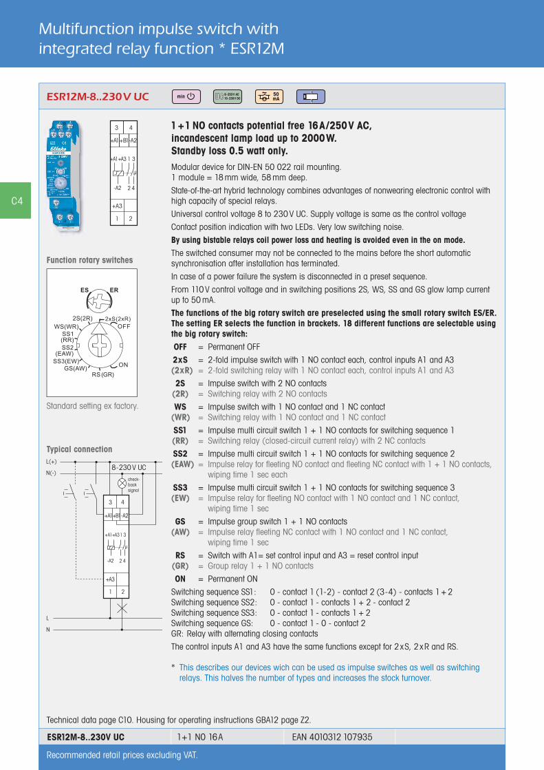
1 +1 NO contacts potential free 16A/250V AC, incandescent lamp load up to 2000W. Standby loss 0.5 watt only.Modular device for DIN-EN 50 022 rail mounting.1 module = 18 mm wide, 58 mm deep.
State-of-the-art hybrid technology combines advantages of nonwearing electronic control withhigh capacity of special relays.
Universal control voltage 8 to 230 V UC. Supply voltage is same as the control voltage
Contact position indication with two LEDs. Very low switching noise.
By using bistable relays coil power loss and heating is avoided even in the on mode. The switched consumer may not be connected to the mains before the short automatic synchronisation after installation has terminated.
In case of a power failure the system is disconnected in a preset sequence.
From 110 V control voltage and in switching positions 2S, WS, SS and GS glow lamp currentup to 50 mA.
The functions of the big rotary switch are preselected using the small rotary switch ES/ER.The setting ER selects the function in brackets. 18 different functions are selectable using the big rotary switch: OFF = Permanent OFF
2xS = 2-fold impulse switch with 1 NO contact each, control inputs A1 and A3 (2xR) = 2-fold switching relay with 1 NO contact each, control inputs A1 and A3
2S = Impulse switch with 2 NO contacts (2R) = Switching relay with 2 NO contacts
WS = Impulse switch with 1 NO contact and 1 NC contact (WR) = Switching relay with 1 NO contact and 1 NC contact
SS1 = Impulse multi circuit switch 1 + 1 NO contacts for switching sequence 1 (RR) = Switching relay (closed-circuit current relay) with 2 NC contacts
SS2 = Impulse multi circuit switch 1 + 1 NO contacts for switching sequence 2 (EAW) = Impulse relay for fleeting NO contact and fleeting NC contact with 1 + 1 NO contacts, wiping time 1 sec each
SS3 = Impulse multi circuit switch 1 + 1 NO contacts for switching sequence 3 (EW) = Impulse relay for fleeting NO contact with 1 NO contact and 1 NC contact, wiping time 1 sec
GS = Impulse group switch 1 + 1 NO contacts (AW) = Impulse relay fleeting NC contact with 1 NO contact and 1 NC contact, wiping time 1 sec
RS = Switch with A1= set control input and A3 = reset control input (GR) = Group relay 1 + 1 NO contacts
ON = Permanent ON
Switching sequence SS1: 0 - contact 1 (1-2) - contact 2 (3-4) - contacts 1 + 2Switching sequence SS2: 0 - contact 1 - contacts 1 + 2 - contact 2Switching sequence SS3: 0 - contact 1 - contacts 1 + 2Switching sequence GS: 0 - contact 1 - 0 - contact 2GR: Relay with alternating closing contacts
The control inputs A1 and A3 have the same functions except for 2xS, 2xR and RS.
* This describes our devices wich can be used as impulse switches as well as switching relays. This halves the number of types and increases the stock turnover.
ESR12M-8..230V UC
Function rotary switches
Standard setting ex factory.
Typical connection
Technical data page C10. Housing for operating instructions GBA12 page Z2.
8-230 V UC
ESR12M-8..230V UC 1+1 N0 16A EAN 4010312 107935
Recommended retail prices excluding VAT.
check-backsignal
C4

1 change over contact potential free 16A/250V AC, incandescent lamp load up to 2000W. No standby loss.Modular device for DIN-EN 50 022 rail mounting.1 module = 18 mm wide, 58 mm deep.
State-of-the-art hybrid technology combines advantages of nonwearing electronic control withhigh capacity of special relays.
Universal control voltage 8 to 230V UC.Low control power demand, therefore substantially less heat is generated.
Integrated free-wheeling anti-surge diode (A1= +, A2= -).Safe disconnection to VDE 0106, Part 101; therefore, these devices can also be used ascoupling relays.By using a bistable relay coil power loss and heating is avoided even in the on mode. The relay contact can be open or closed when putting into operation. It will be synchronised at first operation.
1 change over contact potential free 16A/250V AC, incandescent lamp load up to 2300W. No standby loss.Modular device for DIN-EN 50 022 rail mounting.1 module = 18 mm wide, 58 mm deep.
State-of-the-art hybrid technology combines advantages of nonwearing electronic control withhigh capacity of special relays.
Control voltage 230V.
Low control power demand, therefore substantially less heat is generated.
Low switching noise. Contact position indicator with LED.
Integrated free-wheeling anti-surge diode (A1= +, A2= -).
Safe disconnection to VDE 0106, Part 101; therefore, these devices can also be used ascoupling relays.
Switching, control and coupling relays ER12
ER12-001-230 V
Technical data page C10.
2 change over contacts potential free 10 A/250V AC, incandescent lamp load up to 2000 W. No standby loss.Modular device for DIN-EN 50 022 rail mounting.1 module = 18 mm wide, 58 mm deep.
State-of-the-art hybrid technology combines advantages of nonwearing electronic control withhigh capacity of special relays.
Control voltage 230V.
Low control power demand, therefore substantially less heat is generated.
Low switching noise. Contact position indicator with LED.
Integrated free-wheeling anti-surge diode (A1= +, A2= -).
ER12-002-230 V
ER12-001-8..230 V UC
Technical data page C10.
Technical data page C10.
ER12-001-230V 1 CO 16 A EAN 4010312 200032
2 CO 10 AER12-002-230V EAN 4010312 200063
ER12-001-8..230V UC 1 CO 16 A EAN 4010312 205365
Recommended retail prices excluding VAT.
C5
Multifunktions-Stromstoß-Schaltrelais* ESR12MSwitching relays and control relays ER12Coupling relays KR09
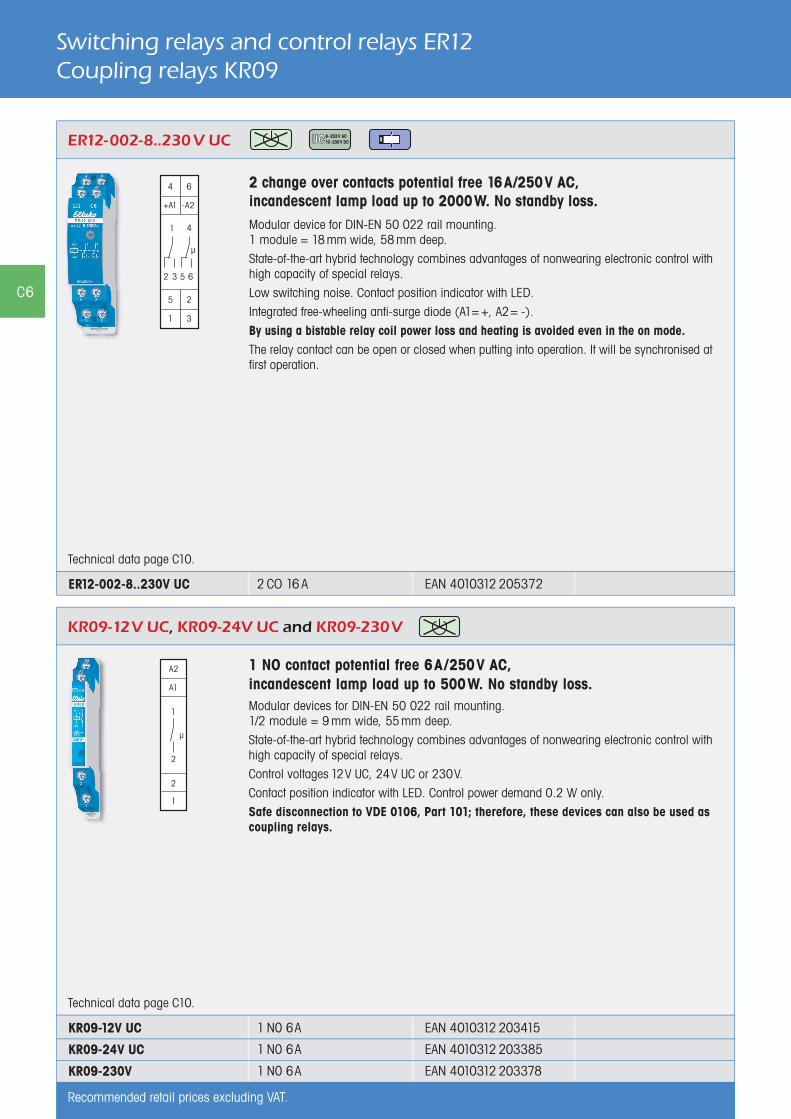
2 change over contacts potential free 16A/250V AC, incandescent lamp load up to 2000W. No standby loss.Modular device for DIN-EN 50 022 rail mounting.1 module = 18 mm wide, 58 mm deep.
State-of-the-art hybrid technology combines advantages of nonwearing electronic control withhigh capacity of special relays.
Low switching noise. Contact position indicator with LED.
Integrated free-wheeling anti-surge diode (A1= +, A2= -).
By using a bistable relay coil power loss and heating is avoided even in the on mode.The relay contact can be open or closed when putting into operation. It will be synchronised at first operation.
ER12-002-8..230 V UC
1 NO contact potential free 6A/250V AC, incandescent lamp load up to 500W. No standby loss.Modular devices for DIN-EN 50 022 rail mounting.1/2 module = 9 mm wide, 55 mm deep.
State-of-the-art hybrid technology combines advantages of nonwearing electronic control withhigh capacity of special relays.
Control voltages 12V UC, 24V UC or 230V.
Contact position indicator with LED. Control power demand 0.2 W only.
Safe disconnection to VDE 0106, Part 101; therefore, these devices can also be used ascoupling relays.
KR09-12V UC, KR09-24V UC and KR09-230V
Technical data page C10.
Technical data page C10.
ER12-002-8..230V UC 2 CO 16 A EAN 4010312 205372
1 N0 6A
1 N0 6A
1 N0 6A
KR09-12V UC
KR09-24V UC
KR09-230V
EAN 4010312 203415
EAN 4010312 203385
EAN 4010312 203378
Recommended retail prices excluding VAT.
C6
C7
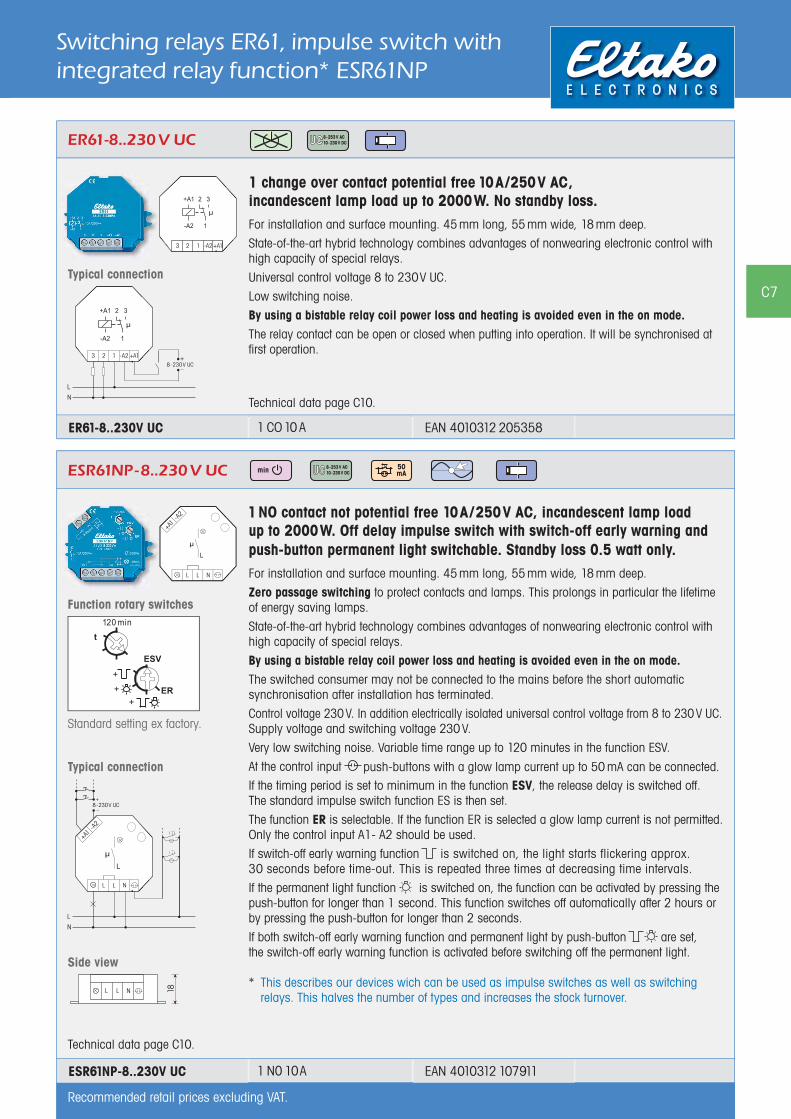
1 NO contact not potential free 10A/250V AC, incandescent lamp load up to 2000W. Off delay impulse switch with switch-off early warning and push-button permanent light switchable. Standby loss 0.5 watt only.For installation and surface mounting. 45 mm long, 55 mm wide, 18 mm deep.
Zero passage switching to protect contacts and lamps. This prolongs in particular the lifetimeof energy saving lamps.
State-of-the-art hybrid technology combines advantages of nonwearing electronic control withhigh capacity of special relays.
By using a bistable relay coil power loss and heating is avoided even in the on mode. The switched consumer may not be connected to the mains before the short automatic synchronisation after installation has terminated.
Control voltage 230 V. In addition electrically isolated universal control voltage from 8 to 230 V UC. Supply voltage and switching voltage 230 V.
Very low switching noise. Variable time range up to 120 minutes in the function ESV.
At the control input push-buttons with a glow lamp current up to 50 mA can be connected.If the timing period is set to minimum in the function ESV, the release delay is switched off.The standard impulse switch function ES is then set.
The function ER is selectable. If the function ER is selected a glow lamp current is not permitted. Only the control input A1- A2 should be used.
If switch-off early warning function is switched on, the light starts flickering approx. 30 seconds before time-out. This is repeated three times at decreasing time intervals.
If the permanent light function is switched on, the function can be activated by pressing the push-button for longer than 1 second. This function switches off automatically after 2 hours or by pressing the push-button for longer than 2 seconds.
If both switch-off early warning function and permanent light by push-button are set,the switch-off early warning function is activated before switching off the permanent light.
* This describes our devices wich can be used as impulse switches as well as switching relays. This halves the number of types and increases the stock turnover.
Switching relays ER61, impulse switch with integrated relay function* ESR61NP
Technical data page C10.
1 change over contact potential free 10A/250V AC, incandescent lamp load up to 2000W. No standby loss.For installation and surface mounting. 45 mm long, 55 mm wide, 18 mm deep.
State-of-the-art hybrid technology combines advantages of nonwearing electronic control withhigh capacity of special relays.
Universal control voltage 8 to 230V UC.
Low switching noise.
By using a bistable relay coil power loss and heating is avoided even in the on mode.The relay contact can be open or closed when putting into operation. It will be synchronised at first operation.
ER61-8..230 V UC
Typical connection
Technical data page C10.
ESR61NP-8..230 V UC
Typical connection
Side view
Function rotary switches
Standard setting ex factory.
Recommended retail prices excluding VAT.
ER61-8..230V UC 1 CO 10 A EAN 4010312 205358
ESR61NP-8..230V UC 1 N0 10A EAN 4010312 107911
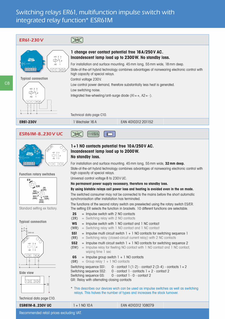
1+1 NO contacts potential free 10A/250V AC. Incandescent lamp load up to 2000W. No standby loss.For installation and surface mounting. 45 mm long, 55 mm wide, 32 mm deep.State-of-the-art hybrid technology combines advantages of nonwearing electronic control withhigh capacity of special relays.
Universal control voltage 8 to 230V UC.
No permanent power supply necessary, therefore no standby loss.By using bistable relays coil power loss and heating is avoided even in the on mode.The switched consumer may not be connected to the mains before the short automatic synchronisation after installation has terminated.
The functions of the second rotary switch are preselected using the rotary switch ES/ER.The setting ER selects the function in brackets. 10 different functions are selectable.
2S = Impulse switch with 2 NO contacts (2R) = Switching relay with 2 NO contacts
WS = Impulse switch with 1 NO contact and 1 NC contact (WR) = Switching relay with 1 NO contact and 1 NC contact
SS1 = Impulse multi circuit switch 1 + 1 NO contacts for switching sequence 1 (RR) = Switching relay (closed-circuit current relay) with 2 NC contacts
SS2 = Impulse multi circuit switch 1 + 1 NO contacts for switching sequence 2 (EW) = Impulse relay for fleeting NO contact with 1 NO contact and 1 NC contact, wiping time 1 sec
GS = Impulse group switch 1 + 1 NO contacts (GR) = Group relay 1 + 1 NO contacts
Switching sequence SS1: 0 - contact 1(1-2) - contact 2 (3-4) - contacts 1 + 2Switching sequence SS2: 0 - contact 1 - contacts 1 + 2 - contact 2Switching sequence GS: 0 - contact 1 - 0 - contact 2GR: Relay with alternating closing contacts
* This describes our devices wich can be used as impulse switches as well as switching relays. This halves the number of types and increases the stock turnover.
ESR61M-8..230 V UC
Function rotary switches
Standard setting ex factory.
Typical connection
Switching relays ER61, multifunction impulse switch with integrated relay function* ESR61M
1 change over contact potential free 16A/250V AC. Incandescent lamp load up to 2300W. No standby loss.For installation and surface mounting. 45 mm long, 55 mm wide, 18 mm deep.
State-of-the-art hybrid technology combines advantages of nonwearing electronic control withhigh capacity of special relays.
Control voltage 230V.
Low control power demand, therefore substantially less heat is generated.
Low switching noise.
Integrated free-wheeling/anti-surge diode (A1= +, A2= -).
ER61-230 V
Technical data page C10.
Typical connection
Technical data page C10.
Side view
1 Wechsler 16 AER61-230V EAN 4010312 201152
1 + 1 N0 10 A EAN 4010312 108079ESR61M-8..230V UC
Recommended retail prices excluding VAT.
C8

Window contactThe window contact as described above is also supplied as individual (accessory) item.
Reed relay with 1 NO contact, switching capacity 5W or VA. Switching voltage max. 175V UC.
FK
Window contact FK
Reed relay and solenoid each 54x12x10mm
FK window contact EAN 4010312 903001
Isolating Relay ETR61NP with window contact FK
1 NO contact not potential free 10A/250V AC. With window contact.Standby loss 0.5 watt only.For installation and surface mounting. 45 mm long, 55 mm wide, 18 mm deep.
State-of-the-art hybrid technology combines advantages of nonwearing electronic control withhigh capacity of special relays.
Control input with internally produced low voltage 24V DC. With an isolating transformer electrically isolated from power supply and make contact (PELV).
Therefore no external low voltage power supply necessary.
With 2 L terminals and 2 N terminals for an easy and quick installation.
The enclosed window contact consists of a Reed relay with terminals and a solenoid. The NC contact opens when the solenoid approaches closer than 25mm. The disconnection relay ETR61NP is connected to terminals T1 and T2. Power supply to the extractor only cuts in when the window is open. ETR61NP can be wired in the flush mounted socket behind the socket for the extractor.
Power supply 230V.
Mounting the window contact FK:Lever out the inserts at the narrow end of the housing. Wire up the Reed relay and cut out the cable entry on the housing. Affix the two housings in parallel maximum 15mm apart and also screw if necessary. In the longitudinal direction the solenoid may be twisted in any direction compared to the Reed relay.
ETR61NP-230V+FK
Technical data page C10.
ETR61NP-230V 1 N0 10 A EAN 4010312 205488
Recommended retail prices excluding VAT.
C9Typical connection
The power supply of an extractor hood is connected by a window contact (NO if window open) so it can be switched on only if the window is open.
Window contact FK
Reed relay and solenoid each 54x12x10mm

Technical data electronic switching relays, control relays and coupling relays
Compliance with: EN 61000-6-3, EN 61000-6-1 and EN 60 669
Contacts
ESR12NP-230V+8..230 V UC a)
ESR12M-8..230 V UC b)
ER12DX-UC a)
ER12-200-8..230 V UC a)
ER12-110-8..230 V UC a)
ER12-001-8..230 V UC a)
ER12-002-8..230V UC a)
ER12-002-230VER61-8..230V UC a)
ESR61NP-8..230 V UC b)
ESR61M 8..230 V UC a)
ETR61NP-230 V
ER12-001-230VER61-230V
KR09-12 V UC,-24 V UC,-230 V
Contact material/contact gap AgSnO2 / 0,5 mm
Spacing of control connections/contact 3mm 6mm3mmETR61NP: 6mm
6mmER61: 3mm
6mm
Spacing of control connectionsC1-C2 or A1-A2/contact
6mm 6mm ESR61NP+M: 6mm -- --
Test voltage contact/contact–
ESR12M: 4000VER12-200/110: 2000V
ER12-002: 2000VESR61M: 2000V
– –
Test voltage control connections/contactTest voltage C1-C2 or A1-A2/contact
2000 V4000 V
4000V--
2000VESR61NP+M+ETR61NP: 4000V
4000 V–
4000 V–
Rated switching capacity 16 A/250 V AC 16 A/250 V AC 10 A/250 V AC 16 A/250 V AC 6A/250V AC
Incandescent lamp and halogen lamp load 1) 230 V
2300 W 2000 W 2000 W 2300W 500 W
Fluorescent lamp load with KVG* in lead-lag circuit or non compensated
1000 VA 1000 VA 1000 VA 1600 VA 600 VA
Fluorescent lamp load with KVG* shunt-compensated or with EVG*
500 VA 500 VA 500 VA 500 VA 300 VA
Compact fl uorescent lamps with EVG*and energy saving lamps ESL
15x7 W10x20 W
I on <_ 70A/ 10ms 2) 3)
I on <_ 70A/ 10ms 2)
ESR61NP: 15x7W,10x20W
I on <_ 70A/ 10ms 2) 52W
Max. switching current DC1: 12 V/24 V DC – 8 A not ESR: 8A 8 A 6 A
Life at rated load, cos = 1 or forincandescent lamps 1000 W at 100/h
> 10 5 > 10 5 > 10 5 > 10 5 > 10 5
Life at rated load,cos = 0.6 at 100/h
> 4 x10⁴ > 4 x10⁴ > 4 x10⁴ > 4 x10⁴ --
Max. operating cycles 103/h 103/h 103/h, ER12: 104/h 104/h 104/h
Contact position indication LED (not series 61)
Terminal cross-section 12 mm2, series 61: clamping screw M3
Maximum conductor cross-section 6 mm2, series 61: 2.5mm2
Screw head slotted/Phillips, pozidriv, series 61: slotted
Shock-hazard protection (on the device) VDE 0106 part 100
Electronics
Time on 100% 100% 100% 100% 100%
Max./min. temperature at mounting location +50°C/-20°C +50°C/-20°C +50°C/-20°C +50°C/-20°C +50°C/-20°C
Stand by loss (active power) 0.5 W only ESR12M: 0.5Wonly ESR61NP + ETR61NP: 0.5W
– –
Control current 230 V control input local ±20%
10 mA – 10 mA, ESR61M: – 10 mA –
Control current universal control voltageall control voltages mA ± 20%
– 4 (not ESR12M) ER12+ER61: 2, ESR61M:4 – –
Control current at 8/12/24/230V (<10s) mA ± 20%
2/4/9/5(100)only ESR12M: 0.1/0.1/0.2/1
only ESR61NP: 2/4/9/5(100)only ETR61NP: 10 mA/24V DC
– –/15/10/11
Max. parallel capacitance (approx. length) of control lead at 230 V AC
ES: 0,3μF (1000 m)ER: 3nF (10 m)C1-C2: 15nF (50 m)
0,5nF (2m)ESR12M: ES: 0,3μF (1000 m)ER: 0,06μF (200 m)ER12DX: 0,06μF (200 m)
0,06μF (200m)ESR61M: 0,5nF (2m)+ER61
0,06μF (200m)
0,06μF (200m)
a) Bistable relay as relay contact. The relay contact can be open or closed when putting into operation. It will be synchronised at fi rst operation. b) Bistable relay as relay contact. The switched consumer may not be connected to the mains before the short automatic synchronisation after installation has terminated. 1) For lamps with 150W max. 2) A 40-fold inrush current must be expected for electronic ballast devices. For steady loads of 1200W or 600W use the current-limiting relay SBR12 or SBR61. Product group G, page G3. 3) If zero passage switching is activated at the ER12DX: 15x7W rsp. 10x20W.
C10
*EVG = electronic ballast units; KVG = conventional ballast units