switched-mode dc power supplies five configurations –flyback –forward –push-pull –half...
Post on 19-Dec-2015
219 views
TRANSCRIPT

Switched-Mode DC Power Supplies
• Five configurations– Flyback– Forward– Push-pull– Half Bridge– Full-Bridge
• Operate at high frequencies– Easy to filter out harmonics

Flyback Converter

Mode 1 Operation -- Q1 ON
• Current builds up in the primary winding• Secondary winding has the opposite polarity D1
OFF• C maintains the output voltage, supplies load
current
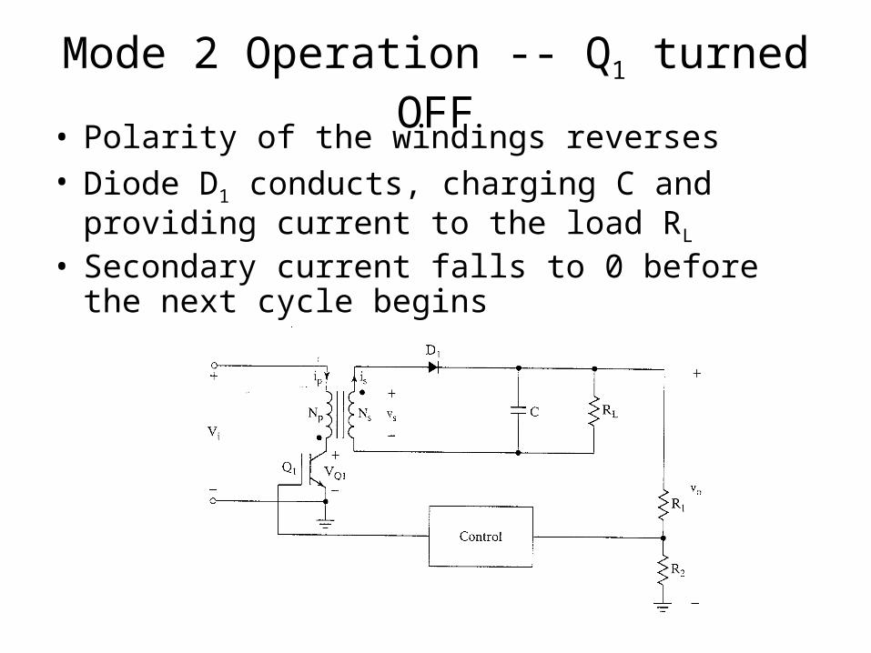
Mode 2 Operation -- Q1 turned OFF• Polarity of the windings reverses• Diode D1 conducts, charging C and providing
current to the load RL
• Secondary current falls to 0 before the next cycle begins

Waveform Summary
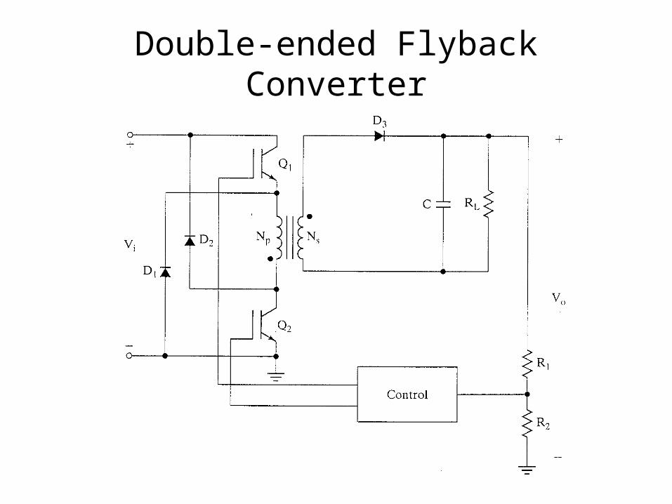
Double-ended Flyback Converter

Forward Converter

Features• Includes a “reset” winding to return energy
• Secondary “dot” so that D2 forward biased when Q1 is ON – no energy stored in the primary
• Operates in continuous mode

Mode 1 Operation -- Q1 ON
• Current builds up in the primary winding• Energy transferred to the load
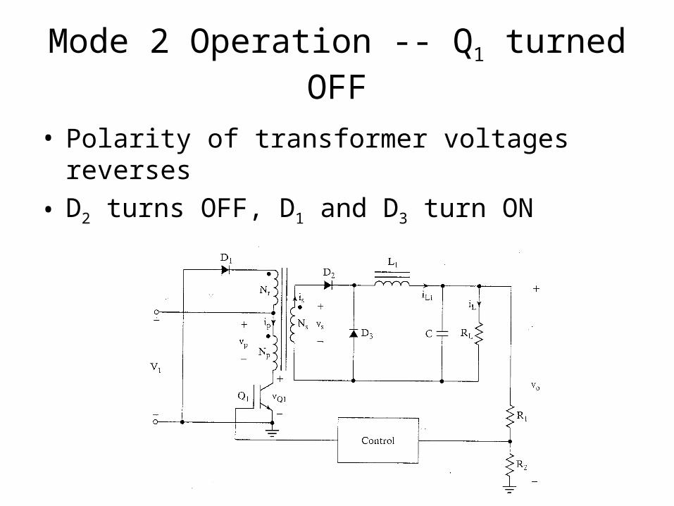
Mode 2 Operation -- Q1 turned OFF
• Polarity of transformer voltages reverses
• D2 turns OFF, D1 and D3 turn ON

Waveform Summary
Vo
D3

Current Components in the Primary

Double-ended Forward Converter

Push-Pull Converter

Push-Pull Operation• Q1 ON, Vs across the lower primary winding
• Q2 ON, Vs across the upper primary winding

Half-Bridge Converter

Mode 1 Operation
• Q1 ON, D1 conducting
• Energy transferred to the load

Mode 2 Operation
• Both transistors are OFF
• D1 continues to conduct due to current in L1

Mode 3 Operation
• Q2 ON, D2 conducting
• Energy transferred to the load
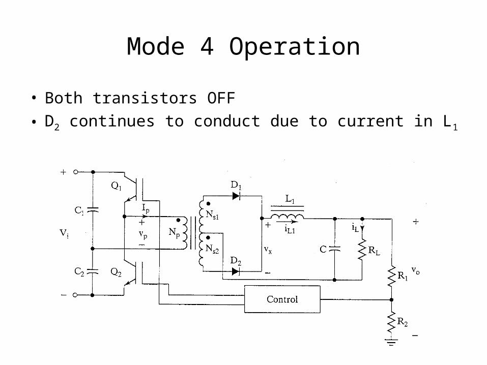
Mode 4 Operation
• Both transistors OFF
• D2 continues to conduct due to current in L1

Waveform Summary – k<0.5

Full-Bridge Converter

Mode 1 Operation
• Q1,Q4 ON, Q2,Q3 OFF
• D1 conducting, energy transferred to the load

Mode 2 Operation
• All transistors are OFF
• D1 continues to conduct due to current in L1

Mode 3 Operation
• Q2,Q3 are ON, Q1,Q4 OFF
• D2 conducting, energy transferred to the load

Mode 4 Operation
• All transistors are OFF
• D2 continues to conduct due to current in L1

Waveform Summary – k<0.5
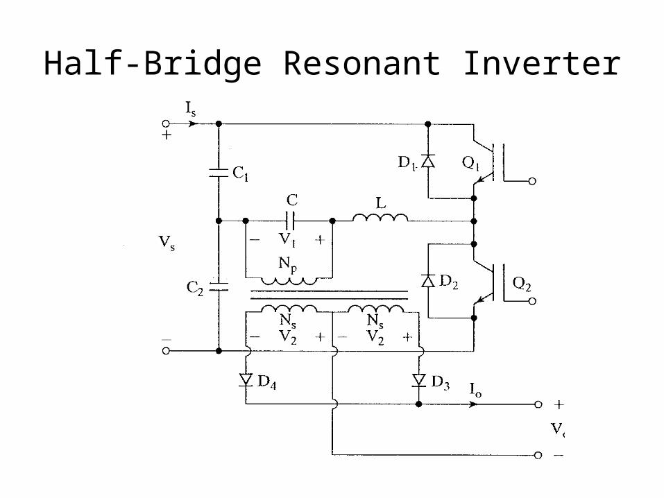
Half-Bridge Resonant Inverter
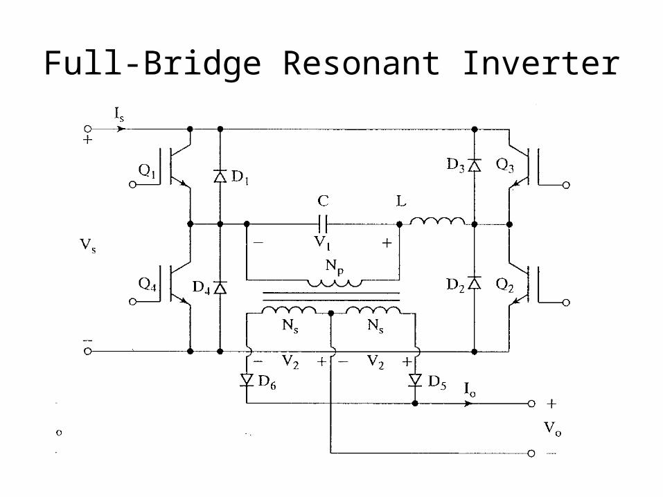
Full-Bridge Resonant Inverter

Bidirectional Power Supply