swift™-60 positioner user guide - agilent · 01-999308-00 a0806 swift-60 positioner1 swift™-60...
TRANSCRIPT
Swift™-60Positioner User
GuideVarian MRI Systems
Pub. No. 01-999308-00, Rev. A0806
01-999308-00 A0806 Swift-60 Positioner 1
Swift™-60 Positioner• Overview, page 1
• Safety Precautions, page 1
• Preparing The Magnet Region, page 2
• Interchanging The Animal Chambers, page 2
• Introducing The Animal To The Chamber, page 3
• Making The Connections, page 4
• Removing the Animal, page 6
OverviewThe Swift™-60 positioner is used for fine positioning of an anesthetized small animal within the bore of small coils installed in a horizontal magnet with a 60-mm gradient insert. The Swift-60 positioner should not be used as an anesthetic induction device. An anesthetized animal should be presented to the positioner. The animal is held in a safe, non-injurious manner, and prepared for the experiment. Provision is made for the introduction of anesthetic gas, monitoring data lines, and temperature control (VT).
There are two Swift-60 positioner products:
• The first product utilizes one 26-mm animal chamber.
• The second product has three interchangeable animal chambers, sized to fit 26, 33, and 39-mm coil inner dimensions. Choose an appropriate configuration for the animal and the test coils. The chamber cover has about 1 mm of diametral clearance within the coil bore.
Safety Precautions
WARNING: Anesthetic gas may cause unconsciousness. Follow your institutional rules and the manufacturer’s instructions/recommendations carefully. Exhaust spent gas safely.
WARNING: Use non-magnetic tools when working near the magnet.
Pub. No. 01-999308-00, A0806
Swift™-60 Positioner
2 Swift-60 Positioner 01-999308-00 A0806
Preparing The Magnet RegionSee the Swift Positioning System (01-999327-00) installation instructions for the Swift Positioning System. The Swift Positioning System extension table supports the Swift-60 positioner.
Interchanging The Animal Chambers
The following steps can be executed with the positioner in your hand or mounted on the extension table (part of the Swift Positioning System).
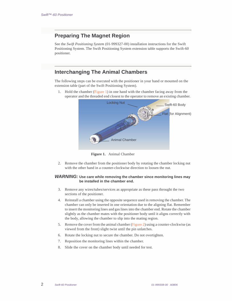
1. Hold the chamber (Figure 1) in one hand with the chamber facing away from the operator and the threaded end closest to the operator to remove an existing chamber.
2. Remove the chamber from the positioner body by rotating the chamber locking nut with the other hand in a counter-clockwise direction to loosen the nut.
WARNING: Use care while removing the chamber since monitoring lines may be installed in the chamber end.
3. Remove any wires/tubes/services as appropriate as these pass throught the two sections of the positioner.
4. Reinstall a chamber using the opposite sequence used in removing the chamber. The chamber can only be inserted in one orientation due to the aligning flat. Remember to insert the monitoring lines and gas lines into the chamber end. Rotate the chamber slightly as the chamber mates with the positioner body until it aligns correctly with the body, allowing the chamber to slip into the mating region.
5. Remove the cover from the animal chamber (Figure 2) using a counter-clockwise (as viewed from the front) slight twist until the pin unlatches.
6. Rotate the locking nut to secure the chamber. Do not overtighten.
7. Reposition the monitoring lines within the chamber.
8. Slide the cover on the chamber body until needed for test.
Figure 1. Animal Chamber
Swift-60 Body
Animal Chamber
Locking Nut
Flat (for Alignment)

01-999308-00 A0806 Swift-60 Positioner 3
Swift™-60 Positioner
9. Animals can be located either headfirst or tailfirst, with the default being headfirst (Figure 3).
• Remove the two screws holding the nose cone in place to change to tailfirst orientation.
• Reverse the nose cone and remount in the appropriate location. Several pairs of holes are available to provide greater flexibility. The longest chamber has a spacer that can be used if the nose cone needs to be mounted higher.
10. The chamber is ready for the animal.
Introducing The Animal To The ChamberFollow the standard animal test procedures for your facility, conforming to government or other requirements, and adapt your processes to use the positioner. The following instructions assume that the positioner is mounted either on the extension table or in a cradle located in the animal preparation area:
1. A gas-exhausting system is required. Position flexible gas funnels near the animal chamber. Turn the exhaust system on and verify that the system is working.
Figure 2. Chamber Cover
Chamber Cover
Latching Pin
Figure 3. Alternate Mounting
Nose Cone
Alternate Mounting Holes
Mounting Screws

Swift™-60 Positioner
4 Swift-60 Positioner 01-999308-00 A0806
2. Turn on the anesthetic gas. The gas exits from the nose cone region of the positioner animal chamber. Position the exhaust nozzles so that a minimum of gas escapes into the lab environment.
3. Remove the chamber cover (Figure 4).
4. The positioner bite bar is adjusted in and out by rolling a thumb wheel with a finger. Apply a slight downward pressure while rotating the thumb wheel, engaging the bite bar.
5. Tighten the thumb screw, which keeps the bite bar from moving once the bite bar is positioned.
6. The animal can be positioned supine (belly-up) or prone (belly-down).
7. Place the animal in the chamber supine for this example.
8. Bring the animal’s nose near the nose cone. Hook the bite bar over the animal’s front teeth and roll the thumb wheel to slightly pull the animal’s head into the nose cone. Tighten the thumb screw.
CAUTION: The thumb wheel has mechanical advantage. Do not damage the animal. Use only enough pressure to hold the animal’s head reasonably steady.
9. Make all monitoring connections needed, such as those for rectal temperature probe, heart monitor, or respiration monitor.
10. Verify that the equipment is working correctly.
11. Slide the cover back onto the chamber, applying a clockwise rotation to the cover to engage the pin.
12. The positioner is ready for the magnet and may be hand-carried over to the magnet.
Making The Connections1. Mount the fine positioner assembly (01-916714-00) on the extension table using two
1/4-20 x 3/4” socket head cap screws (provided).
Figure 4. Animal Adjustments
Nose Cone
Bite Bar
Thumb Screw
Thumb Wheel

01-999308-00 A0806 Swift-60 Positioner 5
Swift™-60 Positioner
2. Insert the positioner into the gradient bore (Figure 5).
Note: There are several bore spacers that align the positioner within the gradient bore. These spacers are spring-loaded using a hook-and-loop material.
3. Slide the positioner into the gradient bore until the clamp block locks into the fine positioner assembly. There should be an audible “click” sound, indicating that the positioner has latched correctly into the fine positioner assembly.
Press the button to the right of the clamp bloc with a finger under the lip of the clamp block to unlatch the positioner from the fine positioner assembly. The positioner should easily disengage from the fine positioner.
4. The position of the clamp block may be changed by loosening the thumbscrew on the side of the clamp block, sliding the block relative to the positioner body, and retightening the thumbscrew.
5. Connect the VT unit to the adapter at the end of the Swift-60 positioner with the positioner latched into the fine positioner assembly. The SA Instruments heater hose
Figure 5. Swift-60 Positioner Insertion Into Gradient Bore
Position Adjusting Knob
Extension Table
Bore Spacer FinePositioner AssemblyMetric Scale
Figure 6. Clamp Block
Locking Thumb Screw
Positioner Body
Thumb here
Finger Here
Fine Positioner Assembly
Scale
SA Instruments Heater Hose
Clamp Block

Swift™-60 Positioner
6 Swift-60 Positioner 01-999308-00 A0806
easily slips into the end of the positioner. Verify that VT gas is flowing (see instructions for SA Instruments monitor/controller operation instructions).
6. Connect the inducing gas line.
7. Connect the monitoring lines.
8. Perform the usual SCOUT or other imaging scan to determine the desired animal location.
9. Rotate the position adjusting knob (Figure 7) to the right of the positioner on the fine positioner assembly, adjusting the position of the animal with respect to the
isocenter. Relative movement is determined by looking at the fine positioner assembly scale. The normal adjustment range is 4 cm. Move the Swift-60 positioner body in the clamp as described in step 4 if a larger adjustment is needed.
10. Perform the experiment.
Removing the Animal1. Take the positioner to the recovery area.
2. Remove the cover.
3. Remove the monitoring equipment in conformance to government and local regulation.
4. Remove the animal for recovery in conformance to government and local regulations.
5. Replace the cover to keep the cradle warm for the next sample.
Figure 7. Animal Position Adjustment
Extension Table
Position Adjusting Knob
Heater Hose
Clamp Block
VT gas

01-999308-00 A0806 Swift-60 Positioner 7
Swift™-60 Positioner
Swift-60 PositionerPub. No. 01-999308-00, Rev. A0806
Technical contributor: Layne HowardTechnical writer: Mike Miller
Technical editor: Everett Schreiber
Revision history:A0806 – Initial release
Copyright © 2006, Varian, Inc. 3120 Hansen Way, Palo Alto, California 943041-800-356-4437http://www.varianinc.comAll rights reserved. Printed in the United States
The information in this document has been carefully checked and is believed to be entirely reliable. However, no responsibility is assumed for inaccuracies. Statements in this document are not intended to create any warranty, expressed or implied. Specifications and performance characteristics of software and hardware described in this manual may be changed at any time without notice. Varian reserves the right to make changes in any products herein to improve reliability, function, or design. Varian does not assume any liability arising out of the application or use of any product or circuit described herein; neither does it convey any license under its patent rights nor the rights of others. Inclusion in this document does not imply that any particular feature is standard on the instrument.
Swift is a registered trademark of Varian, Inc. Other product names are trademarks of their respective holders.