sw camloader v1-0 en
DESCRIPTION
manual lenzeTRANSCRIPT
Global Drive
efesotomasyon.com - Lenze
Manual (Software)
L
Cam Loader
2 DMS-Version 1.0 - 07/2004 - TD16 L
This Manual is valid for the Global Drive Cam Loader as of version 1.0
Copyright
© 2004 Lenze Drive Systems GmbH. All rights reserved.
Imprint
Lenze Drive Systems GmbH
POB 10 13 52, 31763 Hameln, Germany
Phone: ++49 (0)5154 / 82-0
Fax: ++49 (0)5154 / 82-2111
E-mail: [email protected]
Copyright information
All texts, photos and graphics contained in this documentation are subject tocopyright protection. No part of this documentation may be copied or madeavailable to third parties without the explicit written approval of Lenze DriveSystems GmbH.
Liability
All information given in this documentation has been selected carefully andtested for compliance with the described hardware and software.Nevertheless, discrepancies cannot be ruled out. We do not accept anyresponsibility or liability for any damage that may occur. Required correctionswill be included in updates of this documentation.
Trademarks
Microsoft, Windows and Windows NT are either registered trademarks ortrademarks of Microsoft Corporation in the U.S.A. and/or other countries.
Adobe and Reader are either registered trademarks or trademarks of AdobeSystems Incorporated in the U.S.A.and/or other countries.
All other product names contained in this documentation are trademarks ofthe corresponding owners.
efesotomasyon.com - Lenze
Global Drive Cam LoaderContents
efesotomasyon.com - Lenze
Contents
1 About this Manual . . . . . . . . . . . . . . . . . . . . . . . . . . . . . . . . . . . . . . . . . . . . . . . . . . . . . 5
1.1 Conventions used . . . . . . . . . . . . . . . . . . . . . . . . . . . . . . . . . . . . . . . . . . . . . . . . . . . 5
1.2 Layout of the safety information . . . . . . . . . . . . . . . . . . . . . . . . . . . . . . . . . . . . . 6
2 System requirements . . . . . . . . . . . . . . . . . . . . . . . . . . . . . . . . . . . . . . . . . . . . . . . . . . . 7
2.1 Connection with the target system . . . . . . . . . . . . . . . . . . . . . . . . . . . . . . . . . . . 7
3 Software installation . . . . . . . . . . . . . . . . . . . . . . . . . . . . . . . . . . . . . . . . . . . . . . . . . . . 8
4 Introduction . . . . . . . . . . . . . . . . . . . . . . . . . . . . . . . . . . . . . . . . . . . . . . . . . . . . . . . . . . . 9
4.1 Cam Loader applications . . . . . . . . . . . . . . . . . . . . . . . . . . . . . . . . . . . . . . . . . . . . . 9
4.1.1 Control with user interface (GUI mode). . . . . . . . . . . . . . . . . . . . . . . . 10
4.1.2 Control without user interface (batch mode) . . . . . . . . . . . . . . . . . . 11
4.1.3 Commissioning of production machinery. . . . . . . . . . . . . . . . . . . . . . 12
4.2 Creating/preparing import data . . . . . . . . . . . . . . . . . . . . . . . . . . . . . . . . . . . . . . 13
4.2.1 Data format of motion profile data . . . . . . . . . . . . . . . . . . . . . . . . . . . 14
4.2.2 Data format of cam track data . . . . . . . . . . . . . . . . . . . . . . . . . . . . . . . . 14
4.2.3 Data format of position marker data . . . . . . . . . . . . . . . . . . . . . . . . . . 16
5 User interface. . . . . . . . . . . . . . . . . . . . . . . . . . . . . . . . . . . . . . . . . . . . . . . . . . . . . . . . . . 17
5.1 Using the direct help. . . . . . . . . . . . . . . . . . . . . . . . . . . . . . . . . . . . . . . . . . . . . . . . . 17
5.2 Language selection . . . . . . . . . . . . . . . . . . . . . . . . . . . . . . . . . . . . . . . . . . . . . . . . . . 18
5.3 Title bar . . . . . . . . . . . . . . . . . . . . . . . . . . . . . . . . . . . . . . . . . . . . . . . . . . . . . . . . . . . . . 18
5.4 Menu bar . . . . . . . . . . . . . . . . . . . . . . . . . . . . . . . . . . . . . . . . . . . . . . . . . . . . . . . . . . . 18
5.5 Toolbar . . . . . . . . . . . . . . . . . . . . . . . . . . . . . . . . . . . . . . . . . . . . . . . . . . . . . . . . . . . . . 19
5.6 Workspace . . . . . . . . . . . . . . . . . . . . . . . . . . . . . . . . . . . . . . . . . . . . . . . . . . . . . . . . . . 19
5.7 Document window (worksheet) . . . . . . . . . . . . . . . . . . . . . . . . . . . . . . . . . . . . . . 20
5.8 Status bar . . . . . . . . . . . . . . . . . . . . . . . . . . . . . . . . . . . . . . . . . . . . . . . . . . . . . . . . . . . 20
6 Operation . . . . . . . . . . . . . . . . . . . . . . . . . . . . . . . . . . . . . . . . . . . . . . . . . . . . . . . . . . . . . 21
6.1 Creating a new project . . . . . . . . . . . . . . . . . . . . . . . . . . . . . . . . . . . . . . . . . . . . . . . 21
6.1.1 Step 1: Defining the file name and directory for a project. . . . . . . 22
6.1.2 Step 2: Defining the properties of the master . . . . . . . . . . . . . . . . . . 23
6.1.3 Step 3: Defining the properties of the slave . . . . . . . . . . . . . . . . . . . . 24
6.1.4 Step 4: Defining the product properties . . . . . . . . . . . . . . . . . . . . . . . 25
6.2 Opening an existing project . . . . . . . . . . . . . . . . . . . . . . . . . . . . . . . . . . . . . . . . . . 26
L 1.0 EN 3
Global Drive Cam LoaderContents
efesotomasyon.com - Lenze
6.3 Editing the worksheet settings . . . . . . . . . . . . . . . . . . . . . . . . . . . . . . . . . . . . . . . 27
6.3.1 Adding a slave . . . . . . . . . . . . . . . . . . . . . . . . . . . . . . . . . . . . . . . . . . . . . . . 29
6.3.2 Selecting the properties of a slave. . . . . . . . . . . . . . . . . . . . . . . . . . . . . 29
6.3.3 Adding a product. . . . . . . . . . . . . . . . . . . . . . . . . . . . . . . . . . . . . . . . . . . . . 30
6.3.4 Selecting the product properties . . . . . . . . . . . . . . . . . . . . . . . . . . . . . . 31
6.3.5 Defining the import data for a slave/product . . . . . . . . . . . . . . . . . . 32
6.3.6 Creating LCx files . . . . . . . . . . . . . . . . . . . . . . . . . . . . . . . . . . . . . . . . . . . . 33
6.3.7 Deleting a product . . . . . . . . . . . . . . . . . . . . . . . . . . . . . . . . . . . . . . . . . . . 34
6.3.8 Deleting a slave . . . . . . . . . . . . . . . . . . . . . . . . . . . . . . . . . . . . . . . . . . . . . . 34
6.4 Connection with the OPC server . . . . . . . . . . . . . . . . . . . . . . . . . . . . . . . . . . . . . . 35
6.5 Downloading the drive data. . . . . . . . . . . . . . . . . . . . . . . . . . . . . . . . . . . . . . . . . . 35
6.6 Saving a project . . . . . . . . . . . . . . . . . . . . . . . . . . . . . . . . . . . . . . . . . . . . . . . . . . . . . 37
6.7 Saving a project under another name . . . . . . . . . . . . . . . . . . . . . . . . . . . . . . . . . 37
6.8 Creating a template for a script file . . . . . . . . . . . . . . . . . . . . . . . . . . . . . . . . . . . 38
6.9 Closing a project. . . . . . . . . . . . . . . . . . . . . . . . . . . . . . . . . . . . . . . . . . . . . . . . . . . . . 38
6.10 Exiting the Cam Loader . . . . . . . . . . . . . . . . . . . . . . . . . . . . . . . . . . . . . . . . . . . . . . 39
7 Control via script files. . . . . . . . . . . . . . . . . . . . . . . . . . . . . . . . . . . . . . . . . . . . . . . . . . . 40
7.1 Creating a script file . . . . . . . . . . . . . . . . . . . . . . . . . . . . . . . . . . . . . . . . . . . . . . . . . 40
7.2 Script files. . . . . . . . . . . . . . . . . . . . . . . . . . . . . . . . . . . . . . . . . . . . . . . . . . . . . . . . . . . 41
7.2.1 Master settings . . . . . . . . . . . . . . . . . . . . . . . . . . . . . . . . . . . . . . . . . . . . . . 43
7.2.2 Product settings . . . . . . . . . . . . . . . . . . . . . . . . . . . . . . . . . . . . . . . . . . . . . 43
7.2.3 Slave settings . . . . . . . . . . . . . . . . . . . . . . . . . . . . . . . . . . . . . . . . . . . . . . . . 43
7.3 Syntax of the command line start . . . . . . . . . . . . . . . . . . . . . . . . . . . . . . . . . . . . 44
7.4 Log files . . . . . . . . . . . . . . . . . . . . . . . . . . . . . . . . . . . . . . . . . . . . . . . . . . . . . . . . . . . . . 45
8 Appendix. . . . . . . . . . . . . . . . . . . . . . . . . . . . . . . . . . . . . . . . . . . . . . . . . . . . . . . . . . . . . . 46
8.1 Error numbers, causes & remedies. . . . . . . . . . . . . . . . . . . . . . . . . . . . . . . . . . . . 46
8.2 Glossary. . . . . . . . . . . . . . . . . . . . . . . . . . . . . . . . . . . . . . . . . . . . . . . . . . . . . . . . . . . . . 48
9 Index . . . . . . . . . . . . . . . . . . . . . . . . . . . . . . . . . . . . . . . . . . . . . . . . . . . . . . . . . . . . . . . . . 50
4 1.0 EN L

Global Drive Cam LoaderAbout this ManualConventions used
efesotomasyon.com - Lenze
1 About this Manual
This Manual contains information about the Lenze Global Drive Cam Loader V1.0.
The Cam Loader is a software which is used to transfer recipes consisting of motionprofiles, cam tracks and position markers from a PC to Lenze target systems.
Special features of the Cam Loader are:
� Import of CAD data via standardised interfaces (VDI 2143).
� Program operation via an easy-to-use PC user interface for the first commissioning and preparation of additional functions to be provided to the user by the mechanical engineer.
� Program control by means of script files from an IPC for automated processes without additional user entries and recipe extensions through the user.
� Smoothing of imported CAD data (motion profiles) for a smoother running of the drives.
� Recording of all important events.
1.1 Conventions used
This Manual uses the following conventions to distinguish between different types ofinformation:
Type of information Marking Examples/notes
Variable name italics Set bEnable to TRUE to...
Window pane The message window... / The Options dialog box...
Control element bold The OK button... / The Copy command... / The Properties tab... / The Name input field...
Sequence of menu commands
If the execution of a function requires several commands, the individual commands are separated by an arrow: Select File�Open to...
Keyboard command <bold> Use <F1> to call the Online Help.
If a command requires a combination of keys, a "+" is placed between the key symbols:Use <Shift>+<ESC> to...
Program listings Courier IF var1 < var2 THEN a = a + 1 END IF
Keyword Courier bold
Link underlined Links are highlighted references which are activated by means of a mouse click.
Safety information �� �Layout of the safety information (� 6)
Step-by-step instructions � Like safety information, step-by-step instructions and tips can be
recognised by an icon.
Tip �
L 1.0 EN 5
Global Drive Cam LoaderAbout this ManualLayout of the safety information
efesotomasyon.com - Lenze
1.2 Layout of the safety information
All safety information have a uniform structure:
� The icon characterises the type of danger.
� The signal word characterises the severity of danger.
� The note describes the danger and suggests how to avoid the danger.
� Signal word
Note
Icon Signal word Meaning Consequences if disregarded
�hazardous electrical voltage
�general dan-
ger
Danger! Impending danger to persons Death or severe injuries
� Stop! Potential damage to material Damage to the controller or its environment
� Note! Note
6 1.0 EN L
L 1.0 EN 7
Global Drive Cam LoaderSystem requirements
Connection with the target system
2 System requirements
The following minimum requirements on hardware and software must be met in order touse the Cam Loader:
� Microsoft® Windows NT® 4.0 (as of Service Pack 5), Windows® 2000(as of Service Pack 2) or Windows XP
� IBM®-compatible PC with Intel® Pentium® 90 processor
� 64 MB RAM
� 70 MB free hard disk capacity
� Pointer device (mouse, track ball, etc.)
� Free slots/interfaces according to the requirements of the fieldbus connection module used.
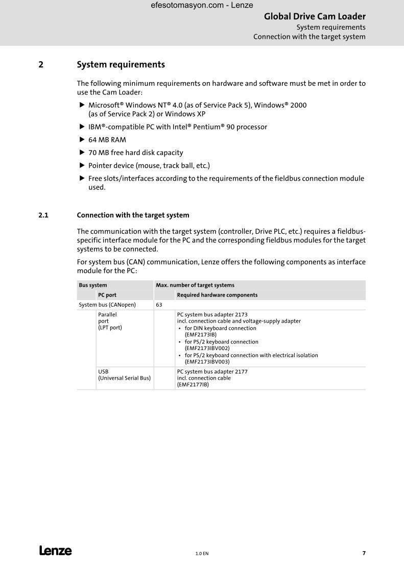
2.1 Connection with the target system
The communication with the target system (controller, Drive PLC, etc.) requires a fieldbus-specific interface module for the PC and the corresponding fieldbus modules for the targetsystems to be connected.
For system bus (CAN) communication, Lenze offers the following components as interfacemodule for the PC:
Bus system Max. number of target systems
PC port Required hardware components
System bus (CANopen) 63
Parallelport(LPT port)
PC system bus adapter 2173incl. connection cable and voltage-supply adapter • for DIN keyboard connection
(EMF2173IB) • for PS/2 keyboard connection
(EMF2173IBV002) • for PS/2 keyboard connection with electrical isolation
(EMF2173IBV003)
USB(Universal Serial Bus)
PC system bus adapter 2177incl. connection cable(EMF2177IB)
efesotomasyon.com - Lenze
Global Drive Cam LoaderSoftware installation
8 1.0 EN L
3 Software installation
� How to install the Cam Loader:
1. Start Windows.
2. Insert the Global Drive Cam Loader CD-ROM into your CD-ROM drive.
If the auto-start function of your CD-ROM drive is active the installation program is started automatically and you can proceed with step 5.
3. Select Run ... from the start menu.
4. Enter the letter for your CD-ROM drive followed by ":\setup.exe" (e.g. "e:\setup.exe") in the command line and confirm with OK.
5. Follow the instructions of the installation program.
� Note!
Installation under Windows NT/2000/XP requires administrator rights!
efesotomasyon.com - Lenze

Global Drive Cam LoaderIntroduction
Cam Loader applications
efesotomasyon.com - Lenze
4 Introduction
� The subsection Cam Loader applications describes the basic proceeding for different Cam Loader applications.
� The subsection Creating/preparing import data explains the data formats of the motion profiles, cam tracks and position markers required for data import. (� 13)
4.1 Cam Loader applications
Depending on the application, the Cam Loader can be used with or without user interface.More information about this can be found in the following subsections:
�Control with user interface (GUI mode) (� 10)
�Control without user interface (batch mode) (� 11)
�Commissioning of production machinery (� 12)
L 1.0 EN 9
Global Drive Cam LoaderIntroductionCam Loader applications
efesotomasyon.com - Lenze
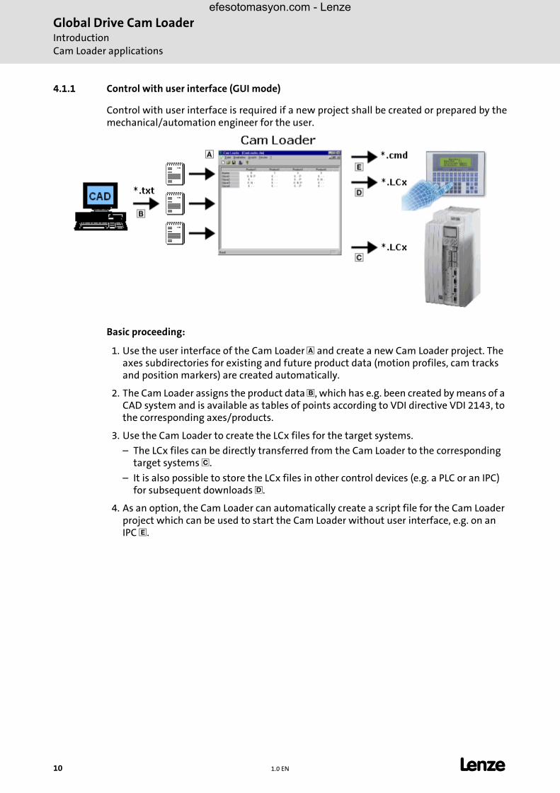
4.1.1 Control with user interface (GUI mode)
Control with user interface is required if a new project shall be created or prepared by themechanical/automation engineer for the user.
Basic proceeding:
1. Use the user interface of the Cam Loader � and create a new Cam Loader project. The axes subdirectories for existing and future product data (motion profiles, cam tracks and position markers) are created automatically.
2. The Cam Loader assigns the product data �, which has e.g. been created by means of a CAD system and is available as tables of points according to VDI directive VDI 2143, to the corresponding axes/products.
3. Use the Cam Loader to create the LCx files for the target systems.
– The LCx files can be directly transferred from the Cam Loader to the corresponding target systems �.
– It is also possible to store the LCx files in other control devices (e.g. a PLC or an IPC) for subsequent downloads �.
4. As an option, the Cam Loader can automatically create a script file for the Cam Loader project which can be used to start the Cam Loader without user interface, e.g. on an IPC �.
10 1.0 EN L
Global Drive Cam LoaderIntroduction
Cam Loader applications
efesotomasyon.com - Lenze
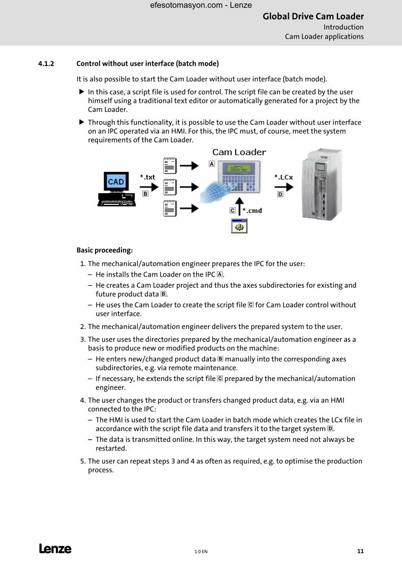
4.1.2 Control without user interface (batch mode)
It is also possible to start the Cam Loader without user interface (batch mode).
� In this case, a script file is used for control. The script file can be created by the user himself using a traditional text editor or automatically generated for a project by the Cam Loader.
� Through this functionality, it is possible to use the Cam Loader without user interface on an IPC operated via an HMI. For this, the IPC must, of course, meet the system requirements of the Cam Loader.
Basic proceeding:
1. The mechanical/automation engineer prepares the IPC for the user:
– He installs the Cam Loader on the IPC �.
– He creates a Cam Loader project and thus the axes subdirectories for existing and future product data �.
– He uses the Cam Loader to create the script file � for Cam Loader control without user interface.
2. The mechanical/automation engineer delivers the prepared system to the user.
3. The user uses the directories prepared by the mechanical/automation engineer as a basis to produce new or modified products on the machine:
– He enters new/changed product data � manually into the corresponding axes subdirectories, e.g. via remote maintenance.
– If necessary, he extends the script file � prepared by the mechanical/automation engineer.
4. The user changes the product or transfers changed product data, e.g. via an HMI connected to the IPC:
– The HMI is used to start the Cam Loader in batch mode which creates the LCx file in accordance with the script file data and transfers it to the target system �.
– The data is transmitted online. In this way, the target system need not always be restarted.
5. The user can repeat steps 3 and 4 as often as required, e.g. to optimise the production process.
L 1.0 EN 11
Global Drive Cam LoaderIntroductionCam Loader applications
efesotomasyon.com - Lenze
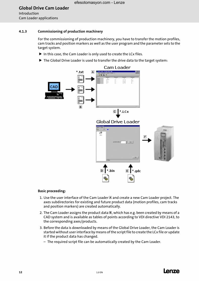
4.1.3 Commissioning of production machinery
For the commissioning of production machinery, you have to transfer the motion profiles,cam tracks and position markers as well as the user program and the parameter sets to thetarget system.
� In this case, the Cam Loader is only used to create the LCx files.
� The Global Drive Loader is used to transfer the drive data to the target system:
Basic proceeding:
1. Use the user interface of the Cam Loader � and create a new Cam Loader project. The axes subdirectories for existing and future product data (motion profiles, cam tracks and position markers) are created automatically.
2. The Cam Loader assigns the product data �, which has e.g. been created by means of a CAD system and is available as tables of points according to VDI directive VDI 2143, to the corresponding axes/products.
3. Before the data is downloaded by means of the Global Drive Loader, the Cam Loader is started without user interface by means of the script file to create the LCx file or update it if the product data has changed.
– The required script file can be automatically created by the Cam Loader.
12 1.0 EN L

Global Drive Cam LoaderIntroduction
Creating/preparing import data
efesotomasyon.com - Lenze
4. The LCx file �, the DDS file � including the compiled user program and the GDC file � including the parameter sets for the corresponding target system are transferred to the Global Drive Loader.
5. After this, the drive data � is downloaded by the Global Drive Loader.
– The Global Drive Loader can also be started by means of a script file. The entire process can thus be automated. (See the documentation for the Global Drive Loader.)
4.2 Creating/preparing import data
For each axis and product number you need an ASCII file including the data of the motionprofile, cam tracks (option) and position markers (option).
� Tip!
The motion profiles and position data are described as tables of points accordingto VDI guideline VDI 2143 "Motion rules for cam mechanisms".
• The required files can be created by means of a CAD system, the Lenze Cam Designer or similar software products.
• Detailed information about the data formats can be found in the following subsections.
� Note!
The latest Global Drive Loader version only supports the 9300 servo PLC and ECS. Support for the 9300 servo cam profiler follows later.
� Note!
The 9300 EK controller (9300 servo cam profiler) does not support cam tracks and position markers!
L 1.0 EN 13

Global Drive Cam LoaderIntroductionCreating/preparing import data
efesotomasyon.com - Lenze
4.2.1 Data format of motion profile data
For data import with the Cam Loader, the motion profile data must be available as an ASCIIfile with the ending *.txt.
� Each line contains the x and y position of a point.
� Comma and point are allowed as decimal symbols.
� Between the two position data there may only be one or several separators (spaces or tab characters).
� After the two position data you can add a comment after at least one separator and two slashes ("//") (option).
� Space lines between the position data are allowed.
� The points must be entered in ascending order of the x positions.
� Each file must contain at least three points.
Example:
4.2.2 Data format of cam track data
For data import with the Cam Loader, the cam track data must be available as an ASCII filewith the ending *.txt.
� For each product number, you can define max. three cam tracks with 4 cams each.
� The cam track data are to be entered as follows:
– Cam type
– Cam reference
– Start/stop value of cam 1
– Start/stop value of cam 2
– Start/stop value of cam 3
– Start/stop value of cam 4
� Note!
If a syntax error occurs during the data import the number of the line in which the syntax error has occurred will be indicated in the optional error message!
10.0 20.0 // point 120.0 30.0 // point 233.3 44.4 // point 355.5 66.6 // point 477.7 88.8 // point 5
14 1.0 EN L
Global Drive Cam LoaderIntroduction
Creating/preparing import data
efesotomasyon.com - Lenze
General notes
� After the cam track data you can add a comment after at least one separator (space or tab character) and two slashes ("//") (option).
� Space lines between the entries are allowed.
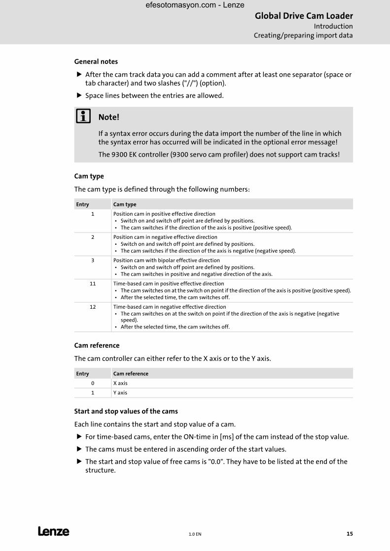
Cam type
The cam type is defined through the following numbers:
Cam reference
The cam controller can either refer to the X axis or to the Y axis.
Start and stop values of the cams
Each line contains the start and stop value of a cam.
� For time-based cams, enter the ON-time in [ms] of the cam instead of the stop value.
� The cams must be entered in ascending order of the start values.
� The start and stop value of free cams is "0.0". They have to be listed at the end of the structure.
� Note!
If a syntax error occurs during the data import the number of the line in which the syntax error has occurred will be indicated in the optional error message!
The 9300 EK controller (9300 servo cam profiler) does not support cam tracks!
Entry Cam type
1 Position cam in positive effective direction • Switch on and switch off point are defined by positions. • The cam switches if the direction of the axis is positive (positive speed).
2 Position cam in negative effective direction • Switch on and switch off point are defined by positions. • The cam switches if the direction of the axis is negative (negative speed).
3 Position cam with bipolar effective direction • Switch on and switch off point are defined by positions. • The cam switches in positive and negative direction of the axis.
11 Time-based cam in positive effective direction • The cam switches on at the switch on point if the direction of the axis is positive (positive speed). • After the selected time, the cam switches off.
12 Time-based cam in negative effective direction • The cam switches on at the switch on point if the direction of the axis is negative (negative
speed). • After the selected time, the cam switches off.
Entry Cam reference
0 X axis
1 Y axis
L 1.0 EN 15
Global Drive Cam LoaderIntroductionCreating/preparing import data
efesotomasyon.com - Lenze
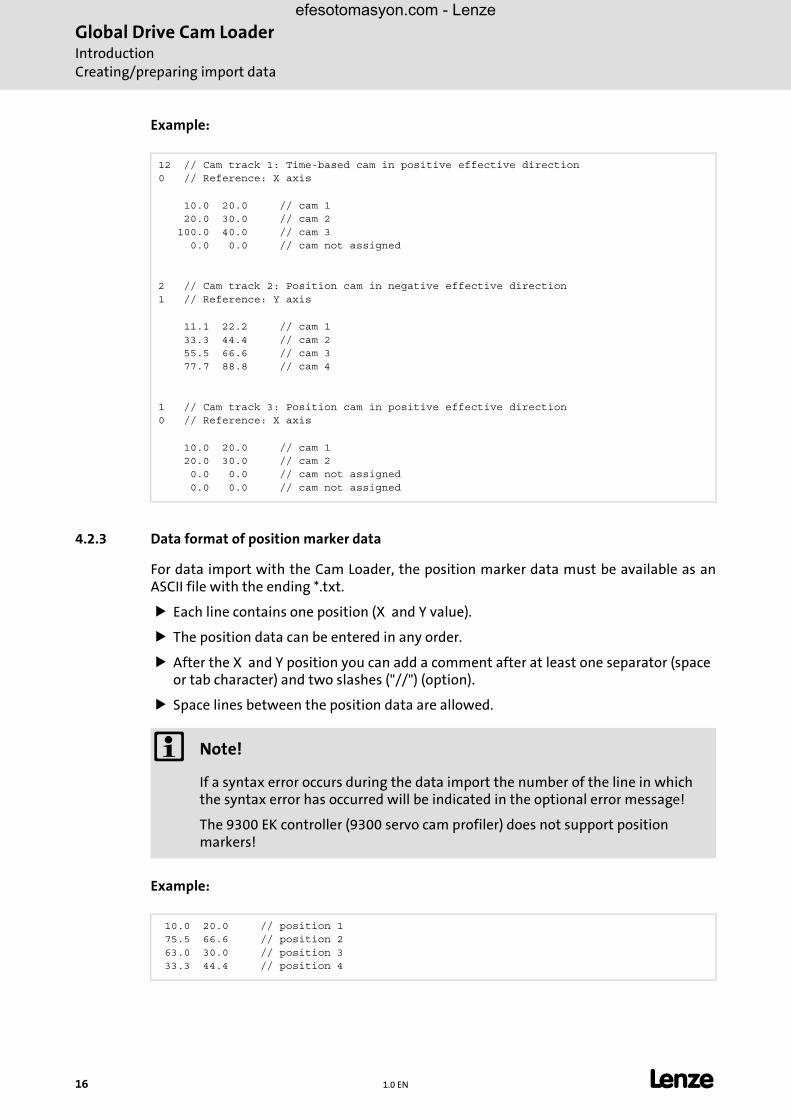
Example:
4.2.3 Data format of position marker data
For data import with the Cam Loader, the position marker data must be available as anASCII file with the ending *.txt.
� Each line contains one position (X and Y value).
� The position data can be entered in any order.
� After the X and Y position you can add a comment after at least one separator (space or tab character) and two slashes ("//") (option).
� Space lines between the position data are allowed.
Example:
12 // Cam track 1: Time-based cam in positive effective direction0 // Reference: X axis
10.0 20.0 // cam 1 20.0 30.0 // cam 2 100.0 40.0 // cam 3 0.0 0.0 // cam not assigned
2 // Cam track 2: Position cam in negative effective direction1 // Reference: Y axis
11.1 22.2 // cam 1 33.3 44.4 // cam 2 55.5 66.6 // cam 3 77.7 88.8 // cam 4
1 // Cam track 3: Position cam in positive effective direction0 // Reference: X axis
10.0 20.0 // cam 1 20.0 30.0 // cam 2 0.0 0.0 // cam not assigned 0.0 0.0 // cam not assigned
� Note!
If a syntax error occurs during the data import the number of the line in which the syntax error has occurred will be indicated in the optional error message!
The 9300 EK controller (9300 servo cam profiler) does not support position markers!
10.0 20.0 // position 1 75.5 66.6 // position 2 63.0 30.0 // position 3 33.3 44.4 // position 4
16 1.0 EN L
Global Drive Cam LoaderUser interface
Using the direct help
efesotomasyon.com - Lenze
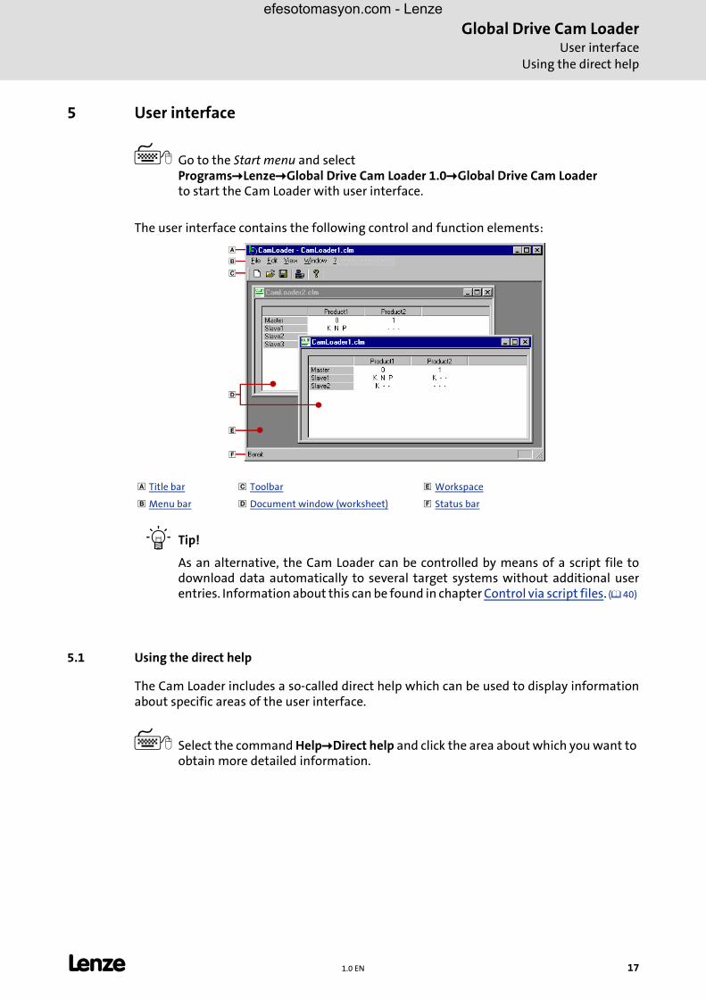
5 User interface
� Go to the Start menu and selectPrograms�Lenze�Global Drive Cam Loader 1.0�Global Drive Cam Loaderto start the Cam Loader with user interface.
The user interface contains the following control and function elements:
� Tip!
As an alternative, the Cam Loader can be controlled by means of a script file todownload data automatically to several target systems without additional userentries. Information about this can be found in chapter Control via script files. (� 40)
5.1 Using the direct help
The Cam Loader includes a so-called direct help which can be used to display informationabout specific areas of the user interface.
� Select the command Help�Direct help and click the area about which you want to obtain more detailed information.
� Title bar � Toolbar � Workspace
� Menu bar � Document window (worksheet) � Status bar
L 1.0 EN 17

Global Drive Cam LoaderUser interfaceLanguage selection
efesotomasyon.com - Lenze
5.2 Language selection
You can always select another language for the menu, dialog and help texts of the CamLoader.
� The available languages depend on the language files that have been installed together with the Cam Loader.
� How to select another language...
1. Select the command View�Select language.
2. Go to the Language configuration dialog box and select the desired language.
3. Click OK to confirm your selection and close the dialog box.
5.3 Title bar
The title bar at the top of the application window shows the program icon and the programname on the left and the window icons on the right.
� With a click on the Window icons ������������������������ you can change the representation of the application window as follows:
– Icon in the task bar (����)
– Full screen (����)
– Window size (����)
� A click on the program icon opens the system menu which also includes commands for positioning and changing the size of the application window.
� A click on the window icon � or a double-click on the program icon closes the Cam Loader.
5.4 Menu bar
The menu commands of the Cam Loader can be accessed via the menu bar.
� A click on an item of the main menu opens the corresponding menu and lists the menu items contained in it.
� Click a menu item to execute the corresponding function.
– Menu items which are displayed in light gray are currently deactivated because the execution of the corresponding function would not make any sense in the current program state.
� Tip!
Many frequently used functions can be executed faster by means of the Toolbaricons. (� 19)
18 1.0 EN L
Global Drive Cam LoaderUser interface
Toolbar
efesotomasyon.com - Lenze
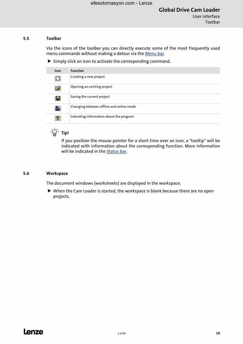
5.5 Toolbar
Via the icons of the toolbar you can directly execute some of the most frequently usedmenu commands without making a detour via the Menu bar.
� Simply click an icon to activate the corresponding command.
� Tip!
If you position the mouse pointer for a short time over an icon, a "tooltip" will beindicated with information about the corresponding function. More informationwill be indicated in the Status bar.
5.6 Workspace
The document windows (worksheets) are displayed in the workspace.
� When the Cam Loader is started, the workspace is blank because there are no open projects.
Icon Function
Creating a new project
Opening an existing project
Saving the current project
Changing between offline and online mode
Indicating information about the program
L 1.0 EN 19

Global Drive Cam LoaderUser interfaceDocument window (worksheet)
efesotomasyon.com - Lenze
5.7 Document window (worksheet)
If you open a project the corresponding worksheet will be indicated in a so-called documentwindow in the Cam Loader Workspace.
By default, the document window is displayed on a full screen, i.e. the document windowfills the whole workspace of the Cam Loader.
� With a click on the window icons ������������������������ at the top right of the document window you can change the representation of the document window as follows:
– Icon within the workspace (����)
– Full screen (����)
– Window size (����)
� A click on the program icon opens the system menu which also includes commands for positioning and changing the size of the document window.
� A click on the window icon � or a double-click on the program icon closes the document window.
� Use the key combination <Strg>+<F6> to jump from one document window to the next document window.
"Window" menu
The Window menu contains the following commands for the arrangement of thedocument window:
5.8 Status bar
The program status is indicated in the status bar.
� Tip!
If you position the mouse pointer over an icon in the Toolbar or a menu commandmore information about the corresponding function will be indicated in the statusbar.
Command Function
New window Opens a new window with the same contents as the active window.In this way, it is possible to display different parts or views of a worksheet simultaneously. • The new window will be automatically the active window and will be indicated above all
other open windows. • If the contents of an open window is changed the contents of all other open windows of
the project changes as well.
Cascade Cascades all windows in the workspace.
Horizontal Arranges all windows in the workspace horizontally.
Arrange icons Arranges all windows reduced to an icon at the bottom of the workspace. • If a window opens in this section, it may happen that one or all icons are hidden because
they are under the window.
1, 2, 3... All open windows are listed at the end of the Window menu.A click on an entry activates the corresponding window (and places it on top of the desktop). • The active window is indicated by a hook in front of the entry.
20 1.0 EN L
Global Drive Cam LoaderOperation
Creating a new project
efesotomasyon.com - Lenze
6 Operation
After the first start of the Cam Loader, the user interface is displayed with an empty work-space.
� Now you can create a new project (worksheet) or open an existing project.
� Tip!
In the installation directory of the Cam Loader you can find example projects whichcan be used to make yourself familiar with the operation of the Cam Loader.
What do you want to do?
�Creating a new project
�Opening an existing project (� 26)
6.1 Creating a new project
New projects are created by means of a wizard which issues a number of queries includingthe file name and directory for the new project as well as the settings for the master, aslave and a product.
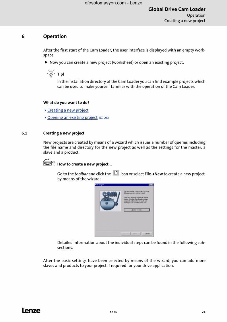
� How to create a new project...
Go to the toolbar and click the icon or select File�New to create a new project by means of the wizard:
Detailed information about the individual steps can be found in the following sub-sections.
After the basic settings have been selected by means of the wizard, you can add moreslaves and products to your project if required for your drive application.
L 1.0 EN 21

Global Drive Cam LoaderOperationCreating a new project
efesotomasyon.com - Lenze
6.1.1 Step 1: Defining the file name and directory for a project
� Tip!
We recommend to create a separate project directory for every new project. TheCam Loader creates a subdirectory for the drive data of each slave.
• All path names within a project are relative and refer to the project directory.
• If you want to transfer a project to another PC, simply copy the project directory to the corresponding PC.
� How to define the file name and directory for a new project...
1. Go to the New project dialog box and click the Project save as button to open the Save as dialog box.
2. Go to the Save as dialog box and select the directory in which you want to store the new project.
3. Go to the File name input field and enter a name for the new project.
4. Click OK to confirm the settings for the new project and close the Save as dialog box.
5. Go to the New project dialog box and click Next to proceed with the next step.
22 1.0 EN L

Global Drive Cam LoaderOperation
Creating a new project
efesotomasyon.com - Lenze
6.1.2 Step 2: Defining the properties of the master
� How to define the properties of the master...
1. Go to the Master dialog box and select the properties of the master.
• The Name of the master is indicated on your worksheet.
• The Cycles are the maximum number of operating cycles per minute.
2. Click Next to proceed with the next step.
L 1.0 EN 23
Global Drive Cam LoaderOperationCreating a new project
efesotomasyon.com - Lenze
6.1.3 Step 3: Defining the properties of the slave
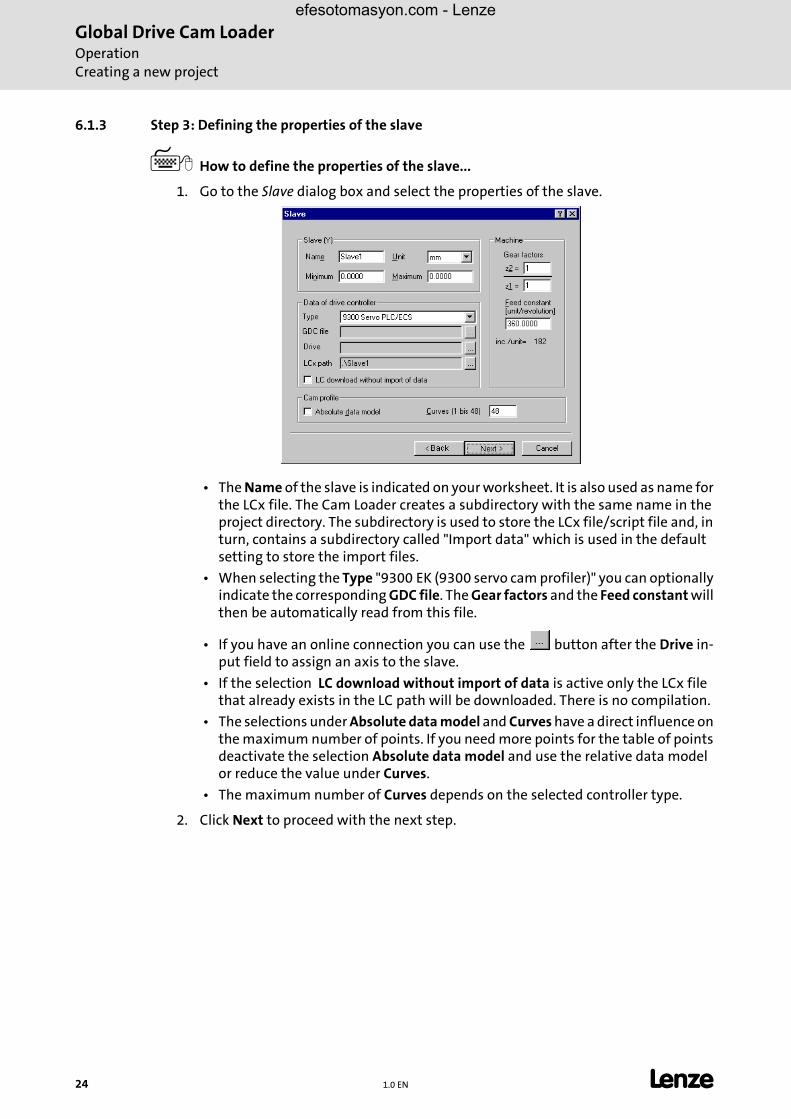
� How to define the properties of the slave...
1. Go to the Slave dialog box and select the properties of the slave.
• The Name of the slave is indicated on your worksheet. It is also used as name for the LCx file. The Cam Loader creates a subdirectory with the same name in the project directory. The subdirectory is used to store the LCx file/script file and, in turn, contains a subdirectory called "Import data" which is used in the default setting to store the import files.
• When selecting the Type "9300 EK (9300 servo cam profiler)" you can optionally indicate the corresponding GDC file. The Gear factors and the Feed constant will then be automatically read from this file.
• If you have an online connection you can use the button after the Drive in-put field to assign an axis to the slave.
• If the selection LC download without import of data is active only the LCx file that already exists in the LC path will be downloaded. There is no compilation.
• The selections under Absolute data model and Curves have a direct influence on the maximum number of points. If you need more points for the table of points deactivate the selection Absolute data model and use the relative data model or reduce the value under Curves.
• The maximum number of Curves depends on the selected controller type.
2. Click Next to proceed with the next step.
24 1.0 EN L
Global Drive Cam LoaderOperation
Creating a new project
efesotomasyon.com - Lenze
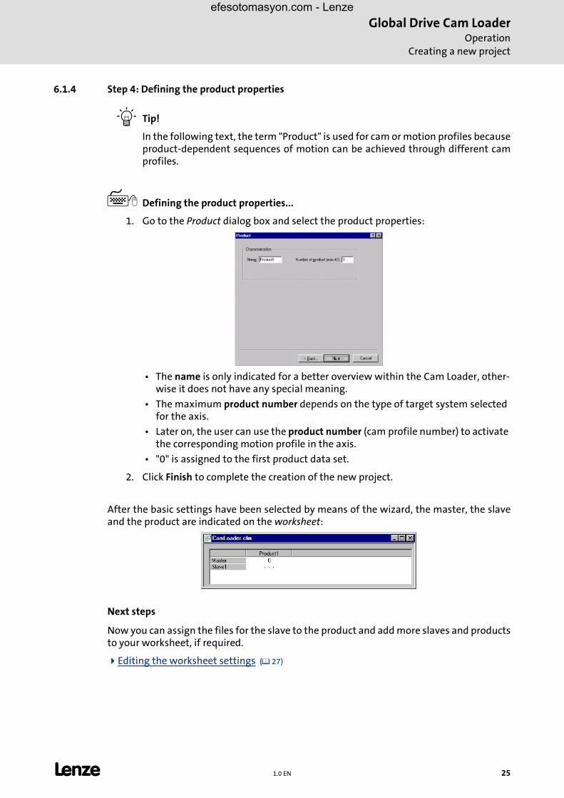
6.1.4 Step 4: Defining the product properties
� Tip!
In the following text, the term "Product" is used for cam or motion profiles becauseproduct-dependent sequences of motion can be achieved through different camprofiles.
� Defining the product properties...
1. Go to the Product dialog box and select the product properties:
• The name is only indicated for a better overview within the Cam Loader, other-wise it does not have any special meaning.
• The maximum product number depends on the type of target system selected for the axis.
• Later on, the user can use the product number (cam profile number) to activate the corresponding motion profile in the axis.
• "0" is assigned to the first product data set.
2. Click Finish to complete the creation of the new project.
After the basic settings have been selected by means of the wizard, the master, the slaveand the product are indicated on the worksheet:
Next steps
Now you can assign the files for the slave to the product and add more slaves and productsto your worksheet, if required.
�Editing the worksheet settings (� 27)
L 1.0 EN 25

Global Drive Cam LoaderOperationOpening an existing project
efesotomasyon.com - Lenze
6.2 Opening an existing project
� Tip!
• It is possible to open several Cam Loader projects (worksheets) simultaneously. The commands for the arrangement of the individual worksheets can be found in the "Window" menu.
• With a click on the entries 1...4 in the File menu you can open one of the four projects edited last.
� How to open an existing project...
1. Go to the toolbar and click the icon or select File�Open.
2. Go to the Open dialog box and select the corresponding project file (*.clm).
3. Click Open .
• After this, the project worksheet will be displayed in the workspace.
Next steps
�Editing the worksheet settings (� 27)
26 1.0 EN L
Global Drive Cam LoaderOperation
Editing the worksheet settings
efesotomasyon.com - Lenze
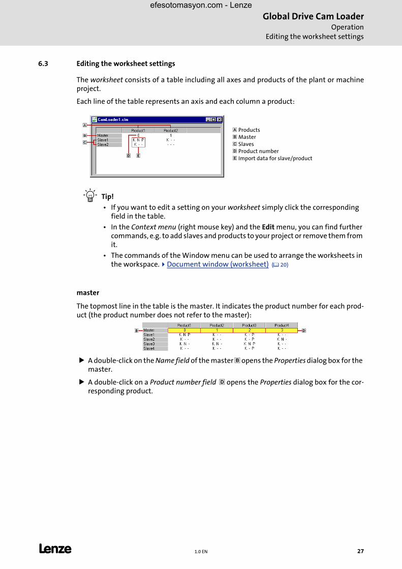
6.3 Editing the worksheet settings
The worksheet consists of a table including all axes and products of the plant or machineproject.
Each line of the table represents an axis and each column a product:
� Tip!
• If you want to edit a setting on your worksheet simply click the corresponding field in the table.
• In the Context menu (right mouse key) and the Edit menu, you can find further commands, e.g. to add slaves and products to your project or remove them from it.
• The commands of the Window menu can be used to arrange the worksheets in the workspace.�Document window (worksheet) (� 20)
master
The topmost line in the table is the master. It indicates the product number for each prod-uct (the product number does not refer to the master):
� A double-click on the Name field of the master � opens the Properties dialog box for the master.
� A double-click on a Product number field � opens the Properties dialog box for the cor-responding product.
� Products� Master� Slaves� Product number� Import data for slave/product
L 1.0 EN 27
Global Drive Cam LoaderOperationEditing the worksheet settings
efesotomasyon.com - Lenze
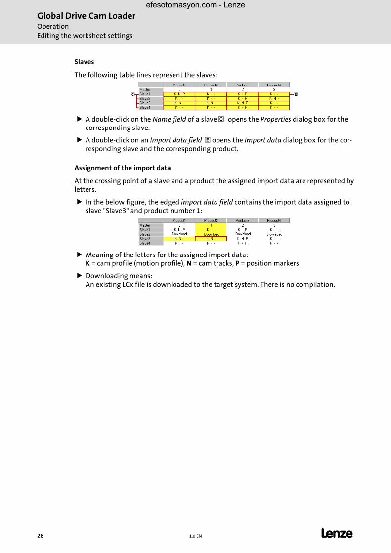
Slaves
The following table lines represent the slaves:
� A double-click on the Name field of a slave � opens the Properties dialog box for the corresponding slave.
� A double-click on an Import data field � opens the Import data dialog box for the cor-responding slave and the corresponding product.
Assignment of the import data
At the crossing point of a slave and a product the assigned import data are represented byletters.
� In the below figure, the edged import data field contains the import data assigned to slave "Slave3" and product number 1:
� Meaning of the letters for the assigned import data:K = cam profile (motion profile), N = cam tracks, P = position markers
� Downloading means:An existing LCx file is downloaded to the target system. There is no compilation.
28 1.0 EN L

Global Drive Cam LoaderOperation
Editing the worksheet settings
efesotomasyon.com - Lenze
6.3.1 Adding a slave
New slaves are added at the end of the list. You can enter a symbolic name for the newslave which will be indicated on your worksheet.
� The name of the slave is also used as name for the LCx file.
� The Cam Loader creates a subdirectory with the same name in the project directory. The subdirectory is used to store the LCx file/script file and, in turn, contains a subdirectory called "Import data" which is used in the default setting to store the import files.
� How to add a slave to your worksheet...
1. Select Edit�Add slave.
2. Go to the Project settings dialog box and enter the name and the properties of the slave.
• The maximum product number determines the minimum number of curves. The maximally possible entry depends on the target system.
�How to define the properties of the slave... (� 24)
3. Click OK to confirm the settings and close the dialog box.
6.3.2 Selecting the properties of a slave
The properties of a slave can always be changed.
� How to change the properties of a slave...
1. Double-click the grey field with the name of the slave whose properties you want to change on your worksheet.
2. Go to the Project settings dialog box and enter the new settings.
�How to define the properties of the slave... (� 24)
3. Click OK to confirm the settings and close the dialog box.
L 1.0 EN 29
Global Drive Cam LoaderOperationEditing the worksheet settings
efesotomasyon.com - Lenze
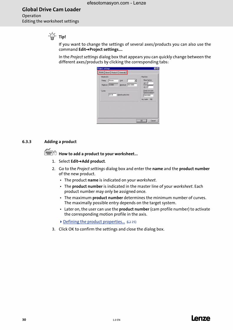
� Tip!
If you want to change the settings of several axes/products you can also use thecommand Edit�Project settings....
In the Project settings dialog box that appears you can quickly change between thedifferent axes/products by clicking the corresponding tabs:
6.3.3 Adding a product
� How to add a product to your worksheet...
1. Select Edit�Add product.
2. Go to the Project settings dialog box and enter the name and the product number of the new product.
• The product name is indicated on your worksheet.
• The product number is indicated in the master line of your worksheet. Each product number may only be assigned once.
• The maximum product number determines the minimum number of curves. The maximally possible entry depends on the target system.
• Later on, the user can use the product number (cam profile number) to activate the corresponding motion profile in the axis.
�Defining the product properties... (� 25)
3. Click OK to confirm the settings and close the dialog box.
30 1.0 EN L

Global Drive Cam LoaderOperation
Editing the worksheet settings
efesotomasyon.com - Lenze
6.3.4 Selecting the product properties
The product properties can always be changed.
� How to change the product properties...
1. Double-click the field with the product number of the product whose properties you want to change on your worksheet.
2. Go to the Project settings dialog box and enter the new settings.
�Defining the product properties... (� 25)
3. Click OK to confirm the settings and close the dialog box.
L 1.0 EN 31
Global Drive Cam LoaderOperationEditing the worksheet settings
efesotomasyon.com - Lenze
6.3.5 Defining the import data for a slave/product
� Tip!
Detailed information about the file format of the import data can be found inchapter "Creating/preparing import data". (� 13)
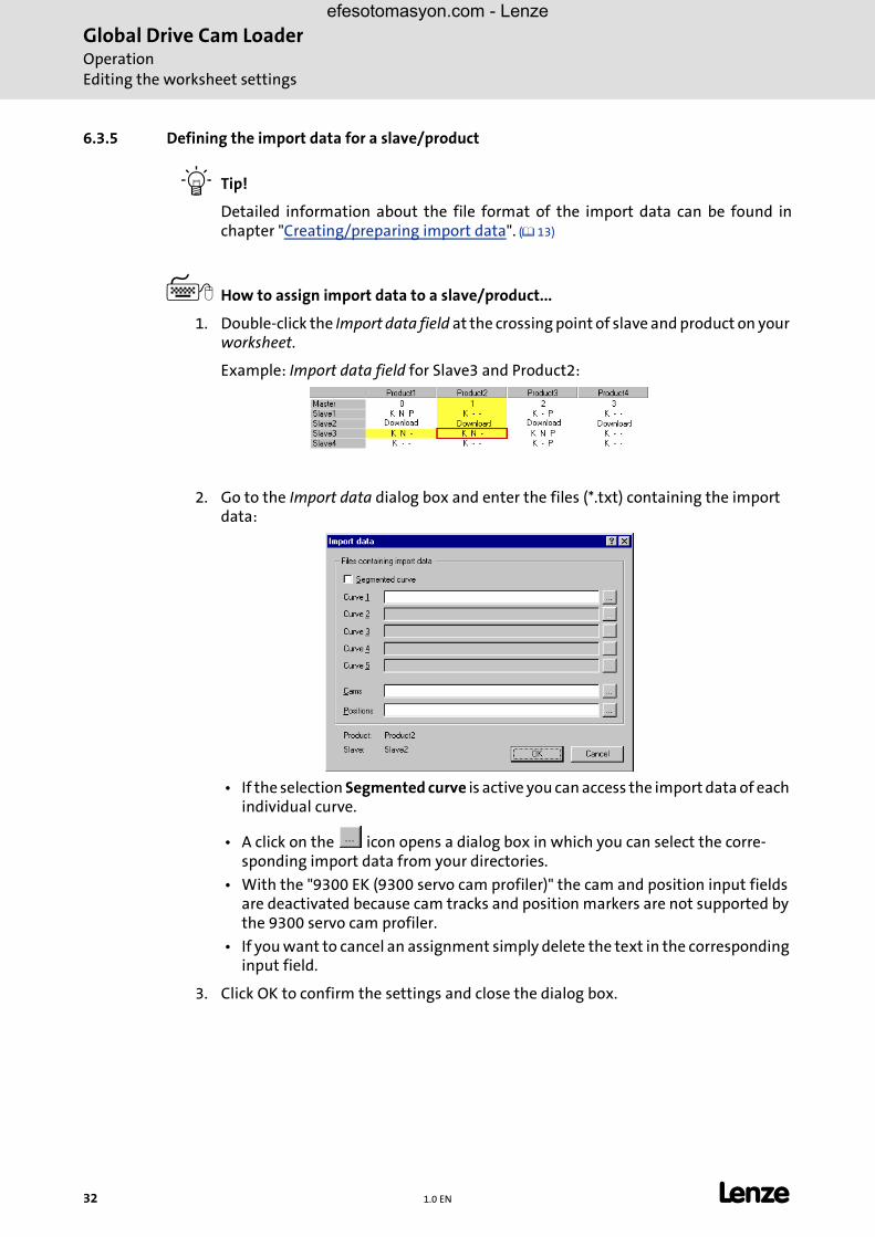
� How to assign import data to a slave/product...
1. Double-click the Import data field at the crossing point of slave and product on your worksheet.
Example: Import data field for Slave3 and Product2:
2. Go to the Import data dialog box and enter the files (*.txt) containing the import data:
• If the selection Segmented curve is active you can access the import data of each individual curve.
• A click on the icon opens a dialog box in which you can select the corre-sponding import data from your directories.
• With the "9300 EK (9300 servo cam profiler)" the cam and position input fields are deactivated because cam tracks and position markers are not supported by the 9300 servo cam profiler.
• If you want to cancel an assignment simply delete the text in the corresponding input field.
3. Click OK to confirm the settings and close the dialog box.
32 1.0 EN L

Global Drive Cam LoaderOperation
Editing the worksheet settings
efesotomasyon.com - Lenze
6.3.6 Creating LCx files
Optionally, you can create the LCx files for one or several slaves simultaneously.
� Each LCx file is assigned to a drive axis. The LCx file contains the motion profiles of the corresponding axis and other axis-specific data. With the 9300 servo PLC and ECS, the LCx file also includes the defined cam tracks and position markers.
� The Cam Loader stores the created LCx files in the subdirectory of the corresponding slaves.
� For "9300 EK (9300 servo cam profiler)" target systems, Cam Loader creates LC7 files, for "9300 servo PLC" and "ECS" target systems LC9 files.
� How to create an LCx file for a slave...
1. Position the mouse pointer over the name field of the slave for which you want to create an LCx file and open the context menu with a click on the right mouse key:
2. Select the command Create LCx file for slave from the context menu.
� How to create LCx files for several slaves simultaneously...
1. Select File�Create LCx file....
2. Go to the Production of LCx files dialog box and select the slaves for which the LCx files shall be created.
• In the default setting, all slaves are selected:
3. Click the Start LCx file button to create the LCx files for the selected slaves and close the dialog box.
L 1.0 EN 33
Global Drive Cam LoaderOperationEditing the worksheet settings
efesotomasyon.com - Lenze
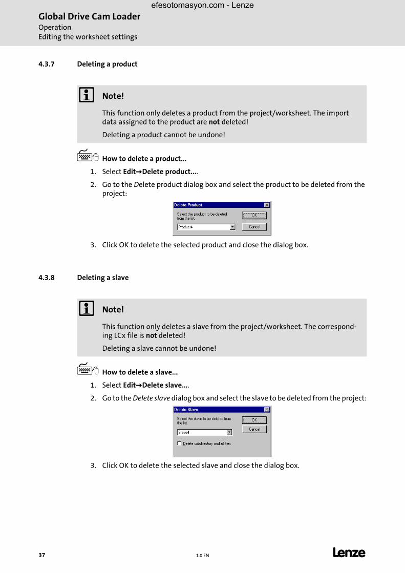
4.3.7 Deleting a product
� How to delete a product...
1. Select Edit�Delete product....
2. Go to the Delete product dialog box and select the product to be deleted from the project:
3. Click OK to delete the selected product and close the dialog box.
4.3.8 Deleting a slave
� How to delete a slave...
1. Select Edit�Delete slave....
2. Go to the Delete slave dialog box and select the slave to be deleted from the project:
3. Click OK to delete the selected slave and close the dialog box.
� Note!
This function only deletes a product from the project/worksheet. The import data assigned to the product are not deleted!
Deleting a product cannot be undone!
� Note!
This function only deletes a slave from the project/worksheet. The correspond-ing LCx file is not deleted!
Deleting a slave cannot be undone!
37 1.0 EN L

Global Drive Cam LoaderOperation
Connection with the OPC server
efesotomasyon.com - Lenze
6.4 Connection with the OPC server
The Lenze DriveServer is used for communication between Cam Loader and target systemand LCx file transfer.
• The DriveServer provides easy integration of drives into open automation structures based on OPC (OLE for Process Control).
• A specially adapted variant of the DriveServer and the bus server for the system bus (CAN) is part of the Cam Loader installation package.
� Select File�Connect to OPC server to connect the Cam Loader to the OPC server or cancel the connection.A hook in front of the menu command indicates the connection with the OPC serv-er.
6.5 Downloading the drive data
If connection with the OPC server has been established it is possible to transfer the drivedata for several slaves in one step. �Connection with the OPC server
� The configuration files (LCx files) for the selected axes are created first.
� If you have an online connection with the corresponding target system the LCx file will be directly transferred to the target system.
� Note!
With the 9300 servo PLC, the LC9 file can only be downloaded if the target sys-tem includes a DDS project based on Template Cam.
L 1.0 EN 35
Global Drive Cam LoaderOperationDownloading the drive data
efesotomasyon.com - Lenze
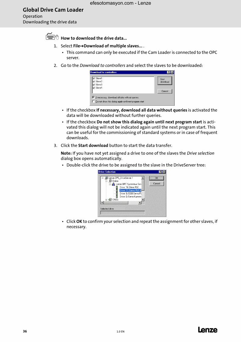
� How to download the drive data...
1. Select File�Download of multiple slaves... .
• This command can only be executed if the Cam Loader is connected to the OPC server.
2. Go to the Download to controllers and select the slaves to be downloaded:
• If the checkbox If necessary, download all data without queries is activated the data will be downloaded without further queries.
• If the checkbox Do not show this dialog again until next program start is acti-vated this dialog will not be indicated again until the next program start. This can be useful for the commissioning of standard systems or in case of frequent downloads.
3. Click the Start download button to start the data transfer.
Note: If you have not yet assigned a drive to one of the slaves the Drive selection dialog box opens automatically.
• Double-click the drive to be assigned to the slave in the DriveServer tree:
• Click OK to confirm your selection and repeat the assignment for other slaves, if necessary.
36 1.0 EN L

Global Drive Cam LoaderOperation
Saving a project
efesotomasyon.com - Lenze
6.6 Saving a project
� Click the icon or select File�Save to save the project.
� Tip!
Save your project at regular intervals to protect your data against power failures orsystem problems.
If you want to create a backup project on another data carrier or in another direc-tory use the command File�Save as... instead.
�Saving a project under another name
6.7 Saving a project under another name
� How to save an open project under another name...
1. Select File�Save as... to pen the Save as dialog box.
2. Go to the Save as list field and select the directory in which you want to store the project.
3. Go to the Name input field and enter a name for the new project.
4. Click OK to save the project under the specified name in the selected directory and close the dialog box.
• If you select the command File�Save the project will be saved with the new set-tings.
� Note!
If you open several Cam Loader projects simultaneously this function refers to the project in the active window.
� Note!
If you open several Cam Loader projects simultaneously this function refers to the project in the active window.
L 1.0 EN 37
Global Drive Cam LoaderOperationCreating a template for a script file
efesotomasyon.com - Lenze
� Tip!
This way you can create a new project or a backup project on another data carrieror in a directory other than the project directory on the basis of the current project.
6.8 Creating a template for a script file
The Cam Loader can automatically create a script file for an open project which can be usedto start the Cam Loader without user interface, e.g. on an IPC.
� Detailed information about the use of script files for Cam Loader control can be found in chapter "Control via script files". (� 40)
� Select the command File�Create script files to create a script file for the current project.
6.9 Closing a project
� Select File�Close to close the open project.
� Note!
The script file can be found under the project name in the corresponding project directory. It has the ending ".cmd".
• In addition, one script file each will be created for each axis and stored under the name of the axis in the corresponding axis subdirectory.
� Note!
If you open several Cam Loader projects simultaneously this function refers to the project in the active window.
38 1.0 EN L

Global Drive Cam LoaderOperation
Exiting the Cam Loader
efesotomasyon.com - Lenze
6.10 Exiting the Cam Loader
� Select File�Exit or click the Window icon � in the Title bar to exit the Cam Loader.
� Note!
If you have not saved the changes made in one or several projects you will be asked if you want to save them before exiting the Cam Loader.
L 1.0 EN 39

Global Drive Cam LoaderControl via script filesCreating a script file
efesotomasyon.com - Lenze
7 Control via script files
When configuring production machinery, it is useful to control the conversion anddownload of the cam profiler data by means of batch files. For this purpose, the CamLoader can be controlled by means of a script file without the need of additional data input.
� For this, the Cam Loader is started with additional program parameters via the command line.
� As an option, the processing results of the script file can be listed in a log file.
7.1 Creating a script file
The Cam Loader can automatically create a script file for an open project which can be usedto start the Cam Loader without user interface, e.g. on an IPC.
� Select the command File�Create script files to create a script file for the current project.
� The script file can be found under the project name in the corresponding project directory. It has the ending ".cmd".
– The script file contains all project axes, i.e. for a complete download you only have to start the Cam Loader with the script file.
� In addition, one script file each will be created for each axis and stored under the name of the axis in the corresponding axis subdirectory.
– The script files can be used to carry out script-controlled downloads to the individual axes.
� Tip!
As an alternative, script files can be created with a traditional text editor. Informa-tion about the script files and an example can be found in the next chapter Scriptfiles. (� 41)
40 1.0 EN L
Global Drive Cam LoaderControl via script files
Script files
efesotomasyon.com - Lenze
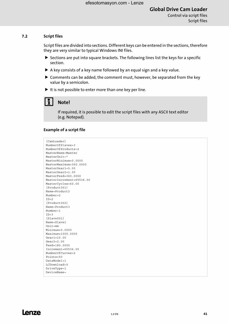
7.2 Script files
Script files are divided into sections. Different keys can be entered in the sections, thereforethey are very similar to typical Windows INI files.
� Sections are put into square brackets. The following lines list the keys for a specific section.
� A key consists of a key name followed by an equal sign and a key value.
� Comments can be added, the comment must, however, be separated from the key value by a semicolon.
� It is not possible to enter more than one key per line.
Example of a script file
� Note!
If required, it is possible to edit the script files with any ASCII text editor (e.g. Notepad).
[CamLoader]NumberOfSlaves=3NumberOfProducts=2MasterName=MasterMasterUnit=°MasterMinimum=0.0000MasterMaximum=360.0000MasterGear1=5.00MasterGear2=1.00MasterFeed=360.0000MasterIncrement=65536.00MasterCycles=60.00[Product001]Name=Product2Number=2ID=2[Product002]Name=Product3Number=1ID=3[Slave001]Name=Slave1Unit=mmMinimum=0.0000Maximum=1000.0000Gear1=10.00Gear2=2.00Feed=180.0000Increment=65536.00NumberOfCurves=2Points=50DataModel=1LCDownload=0DriveType=1DeviceName=
L 1.0 EN 41

Global Drive Cam LoaderControl via script filesScript files
efesotomasyon.com - Lenze
ParameterSetFile=.\Slave1\LC7_beispiel.GDCLC-Path=.\Slave1Segmented002=1PathCurve002=.\Slave1\Importdata\Segment1.txtPathCurve_B002=.\Slave1\Importdata\Segment2.txtPathCurve_C002=.\Slave1\Importdata\Segment3.txtPathCurve_D002=.\Slave1\Importdata\Segment4.txtPathCurve_E002=.\Slave1\Importdata\Segment5.txtPathPosition002=.\Slave1\Importdata\Pos1.txtSegmented003=0[Slave002]Name=Slave2Unit=mmMinimum=0.0000Maximum=0.0000Gear1=1.00Gear2=1.00Feed=360.0000Increment=65536.00NumberOfCurves=2Points=50DataModel=0LCDownload=1DriveType=0DeviceName=ParameterSetFile=LC-Path=.\Slave2Segmented002=0Segmented003=0[Slave003]Name=Slave3Unit=mmMinimum=0.0000Maximum=0.0000Gear1=1.00Gear2=1.00Feed=360.0000Increment=65536.00NumberOfCurves=2Points=50DataModel=0LCDownload=0DriveType=0DeviceName=ParameterSetFile=LC-Path=.\Slave3Segmented002=0Segmented003=0PathCurve003=.\Slave3\Importdata\LineRel500.txtPathPosition003=.\Slave3\Importdata\Point1.txt
42 1.0 EN L
Global Drive Cam LoaderControl via script files
Script files
efesotomasyon.com - Lenze
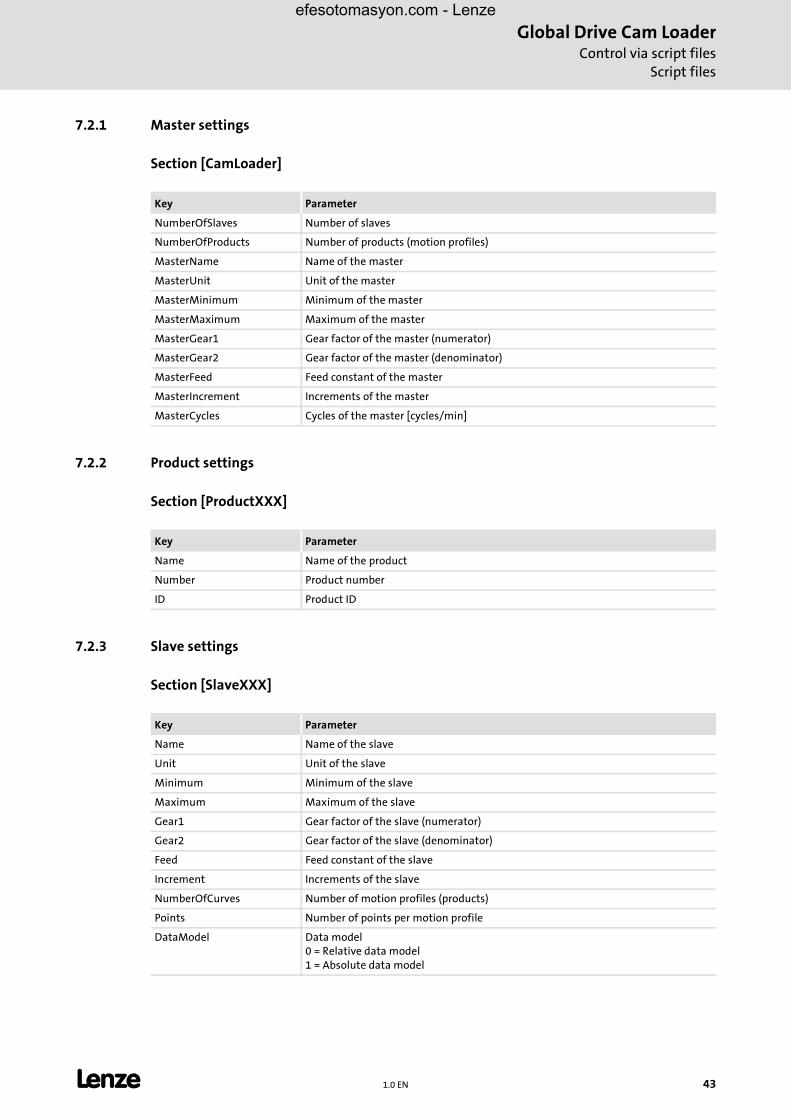
7.2.1 Master settings
Section [CamLoader]
7.2.2 Product settings
Section [ProductXXX]
7.2.3 Slave settings
Section [SlaveXXX]
Key Parameter
NumberOfSlaves Number of slaves
NumberOfProducts Number of products (motion profiles)
MasterName Name of the master
MasterUnit Unit of the master
MasterMinimum Minimum of the master
MasterMaximum Maximum of the master
MasterGear1 Gear factor of the master (numerator)
MasterGear2 Gear factor of the master (denominator)
MasterFeed Feed constant of the master
MasterIncrement Increments of the master
MasterCycles Cycles of the master [cycles/min]
Key Parameter
Name Name of the product
Number Product number
ID Product ID
Key Parameter
Name Name of the slave
Unit Unit of the slave
Minimum Minimum of the slave
Maximum Maximum of the slave
Gear1 Gear factor of the slave (numerator)
Gear2 Gear factor of the slave (denominator)
Feed Feed constant of the slave
Increment Increments of the slave
NumberOfCurves Number of motion profiles (products)
Points Number of points per motion profile
DataModel Data model0 = Relative data model1 = Absolute data model
L 1.0 EN 43
Global Drive Cam LoaderControl via script filesSyntax of the command line start
efesotomasyon.com - Lenze
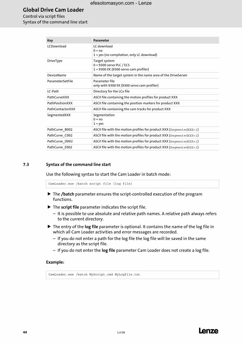
7.3 Syntax of the command line start
Use the following syntax to start the Cam Loader in batch mode:
� The /batch parameter ensures the script-controlled execution of the program functions.
� The script file parameter indicates the script file.
– It is possible to use absolute and relative path names. A relative path always refers to the current directory.
� The entry of the log file parameter is optional. It contains the name of the log file in which all Cam Loader activities and error messages are recorded.
– If you do not enter a path for the log file the log file will be saved in the same directory as the script file.
– If you do not enter the log file parameter Cam Loader does not create a log file.
Example:
LCDownload LC download0 = no1 = yes (no compilation, only LC download)
DriveType Target system0 = 9300 servo PLC / ECS1 = 9300 EK (9300 servo cam profiler)
DeviceName Name of the target system in the name area of the DriveServer
ParameterSetFile Parameter file only with 9300 EK (9300 servo cam profiler)
LC-Path Directory for the LCx file
PathCurveXXX ASCII file containing the motion profiles for product XXX
PathPositionXXX ASCII file containing the position markers for product XXX
PathContactorXXX ASCII file containing the cam tracks for product XXX
SegmentedXXX Segmentation0 = no1 = yes
PathCurve_B002 ASCII file with the motion profiles for product XXX (SegmentedXXX=1)
PathCurve_C002 ASCII file with the motion profiles for product XXX (SegmentedXXX=1)
PathCurve_D002 ASCII file with the motion profiles for product XXX (SegmentedXXX=1)
PathCurve_E002 ASCII file with the motion profiles for product XXX (SegmentedXXX=1)
Key Parameter
CamLoader.exe /batch script file [log file]
CamLoader.exe /batch MyScript.cmd MyLogfile.txt
44 1.0 EN L
Global Drive Cam LoaderControl via script files
Log files
efesotomasyon.com - Lenze
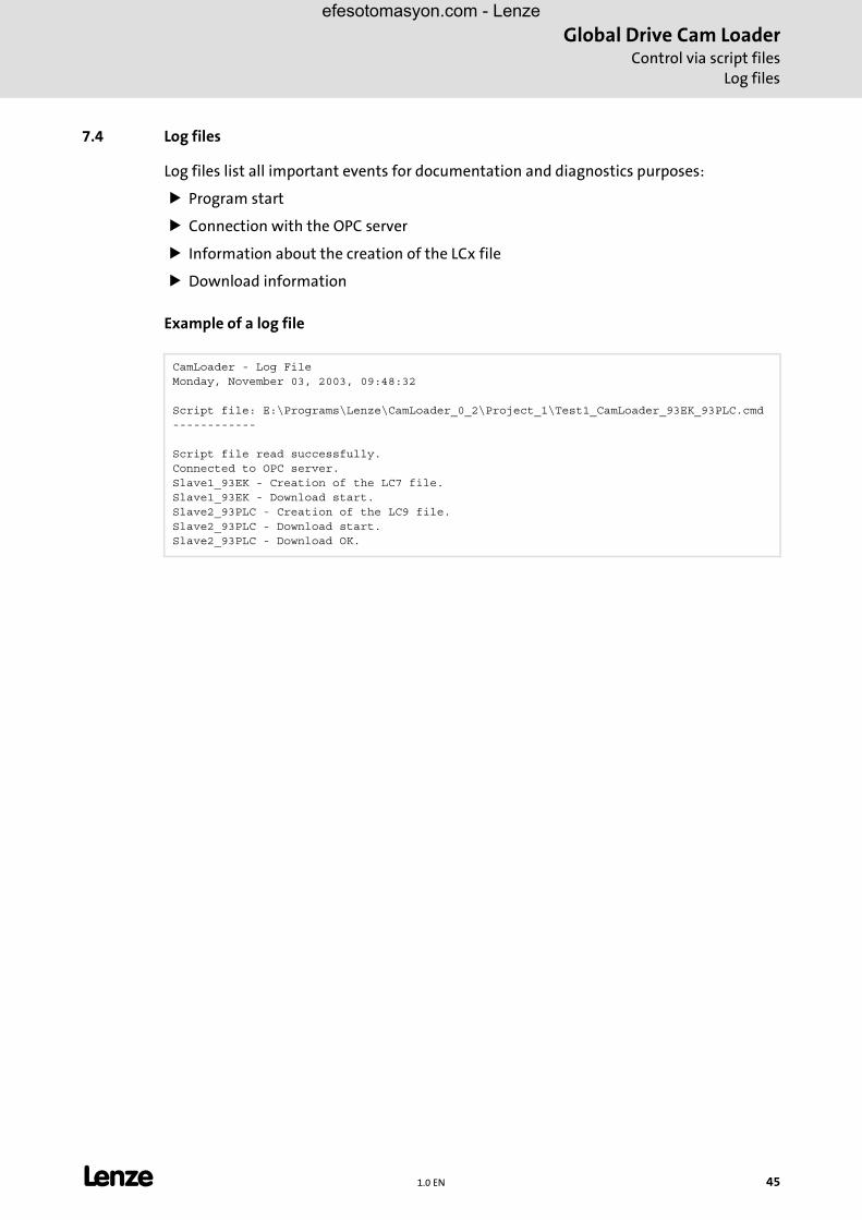
7.4 Log files
Log files list all important events for documentation and diagnostics purposes:
� Program start
� Connection with the OPC server
� Information about the creation of the LCx file
� Download information
Example of a log file
CamLoader - Log FileMonday, November 03, 2003, 09:48:32
Script file: E:\Programs\Lenze\CamLoader_0_2\Project_1\Test1_CamLoader_93EK_93PLC.cmd------------
Script file read successfully.Connected to OPC server.Slave1_93EK - Creation of the LC7 file. Slave1_93EK - Download start.Slave2_93PLC - Creation of the LC9 file. Slave2_93PLC - Download start.Slave2_93PLC - Download OK.
L 1.0 EN 45
Global Drive Cam LoaderAppendixError numbers, causes & remedies
efesotomasyon.com - Lenze
8 Appendix
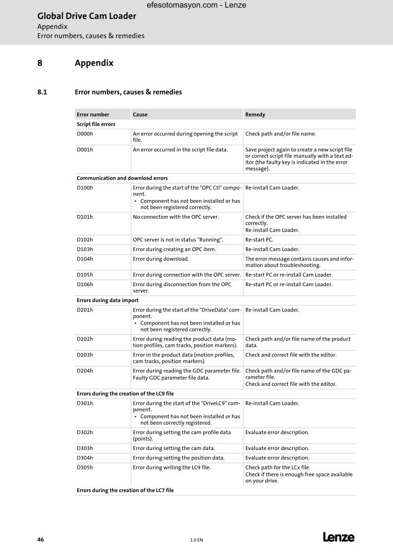
8.1 Error numbers, causes & remedies
Error number Cause Remedy
Script file errors
D000h An error occurred during opening the script file.
Check path and/or file name.
D001h An error occurred in the script file data. Save project again to create a new script file or correct script file manually with a text ed-itor (the faulty key is indicated in the error message).
Communication and download errors
D100h Error during the start of the "OPC Ctl" compo-nent. • Component has not been installed or has
not been registered correctly.
Re-install Cam Loader.
D101h No connection with the OPC server. Check if the OPC server has been installed correctly.Re-install Cam Loader.
D102h OPC server is not in status "Running". Re-start PC.
D103h Error during creating an OPC item. Re-install Cam Loader.
D104h Error during download. The error message contains causes and infor-mation about troubleshooting.
D105h Error during connection with the OPC server. Re-start PC or re-install Cam Loader.
D106h Error during disconnection from the OPC server.
Re-start PC or re-install Cam Loader.
Errors during data import
D201h Error during the start of the "DriveData" com-ponent. • Component has not been installed or has
not been registered correctly.
Re-install Cam Loader.
D202h Error during reading the product data (mo-tion profiles, cam tracks, position markers).
Check path and/or file name of the product data.
D203h Error in the product data (motion profiles, cam tracks, position markers).
Check and correct file with the editor.
D204h Error during reading the GDC parameter file.Faulty GDC parameter file data.
Check path and/or file name of the GDC pa-rameter file.Check and correct file with the editor.
Errors during the creation of the LC9 file
D301h Error during the start of the "DriveLC9" com-ponent. • Component has not been installed or has
not been correctly registered.
Re-install Cam Loader.
D302h Error during setting the cam profile data (points).
Evaluate error description.
D303h Error during setting the cam data. Evaluate error description.
D304h Error during setting the position data. Evaluate error description.
D305h Error during writing the LC9 file. Check path for the LCx file.Check if there is enough free space available on your drive.
Errors during the creation of the LC7 file
46 1.0 EN L
Global Drive Cam LoaderAppendix
Error numbers, causes & remedies
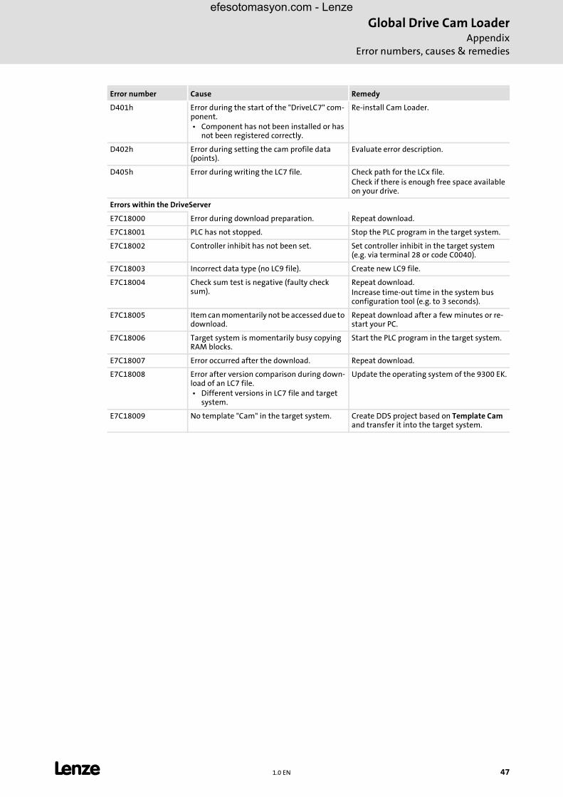
efesotomasyon.com - Lenze
D401h Error during the start of the "DriveLC7" com-ponent. • Component has not been installed or has
not been registered correctly.
Re-install Cam Loader.
D402h Error during setting the cam profile data (points).
Evaluate error description.
D405h Error during writing the LC7 file. Check path for the LCx file.Check if there is enough free space available on your drive.
Errors within the DriveServer
E7C18000 Error during download preparation. Repeat download.
E7C18001 PLC has not stopped. Stop the PLC program in the target system.
E7C18002 Controller inhibit has not been set. Set controller inhibit in the target system (e.g. via terminal 28 or code C0040).
E7C18003 Incorrect data type (no LC9 file). Create new LC9 file.
E7C18004 Check sum test is negative (faulty check sum).
Repeat download.Increase time-out time in the system bus configuration tool (e.g. to 3 seconds).
E7C18005 Item can momentarily not be accessed due to download.
Repeat download after a few minutes or re-start your PC.
E7C18006 Target system is momentarily busy copying RAM blocks.
Start the PLC program in the target system.
E7C18007 Error occurred after the download. Repeat download.
E7C18008 Error after version comparison during down-load of an LC7 file. • Different versions in LC7 file and target
system.
Update the operating system of the 9300 EK.
E7C18009 No template "Cam" in the target system. Create DDS project based on Template Cam and transfer it into the target system.
Error number Cause Remedy
L 1.0 EN 47
Global Drive Cam LoaderAppendixGlossary
efesotomasyon.com - Lenze
8.2 Glossary
A
Absolute data model Contains both the X and the Y coordinate. Therefore requires more space thanthe relative data model. The points are 1:1 transferred from the Cam Loader tothe target system:
• Advantage: The distance between the points can be variable. This allows to optimise the distribution of the points according to the cam profile charac-teristics.
• Disadvantage: Compared to the relative data model, less points can be saved.
�Relative data model
Application window Window in which programs are displayed under Windows.
C
Code Lenze device parameter used to select the device functionality.
COM Abbreviation for "Component Object Model": Architecture developed by Mi-crosoft® for the interaction of separately executable software components(objects) that communicate with each other in the same way and are only con-nected to each other when the program is being executed.
D
DCOM Abbreviation for "Distributed Component Object Model": COM in which theexecutable objects can be distributed to different computers within a localnetwork.
�COM
DDS Abbreviation for "Drive PLC Developer Studio": Development environment forthe creation of IEC 61131 programs for Lenze PLCs.
Document window Window with graphical user interface displayed by a user program in which adocument is created, displayed and edited. Document windows are usuallysub-windows of the program windows.
Drive PLC Developer Studio See DDS.
DriveServer Lenze software which enables easy integration of drives into open automa-tion structures based on OPC ("OLE for Process Control").
�OPC
G
Global Drive Loader Lenze software used to transfer PLC programs, parameter sets and applicationdata to Lenze target systems.
H
Hyperlink Highlighted reference which is activated by a mouse click.
48 1.0 EN L
Global Drive Cam LoaderAppendix
Glossary
efesotomasyon.com - Lenze
I
IPC Abbreviation for Industrial PC. Industrial PCs are used in case of special envi-ronmental conditions, e.g. dirt or vibrations. They are slot CPUs with powerfulprocessors and TFT displays (often with touch screens).
O
OLE Abbreviation for "Object Linking and Embedding": Integration of operationalobjects into other applications, e.g. Microsoft® Excel spreadsheets into Micro-soft® Word documents.
OPC Abbreviation for "OLE for Process Control": Defines an interface based on theMicrosoft® Windows® technologies OLE, COM and DCOM which enables dataexchange between different automation devices and PC programs regardlessof driver and interface problems.
�COM�DCOM
P
PDF Abbreviation for "Portable Document Format". Universal file format devel-oped by Adobe for the exchange of electronic documents. The Adobe® Read-er® is provided free of charge and can be used to display and print PDF filesindependently of the application and platform used to create them.
PLC Abbreviation for "Programmable Logic Controller".
R
Relative data model Only contains the difference between adjacent Y coordinates and therefore re-quires less space than the absolute data model. The distance between the Xcoordinates is transferred as a fixed-comma value to the target system. Thisleads to a certain difference between the imported data and the coordinatescalculated by the target system. To compensate for this inaccuracy, the Y val-ues are re-calculated by means of interpolation .
• Advantage: Compared to the absolute data model, more points can be saved.
• Disadvantage: The distance between the X coordinates of the points must always be the same.
�Absolute data model
T
Title bar Bar at the top of the application window including the program icon and theprogram name on the left and the window icons on the right.
V
VDI 2143 VDI guideline "Motion rules for cam mechanisms"
W
Window icon Button at the right end of the title bar which can be used to change the size ofthe window or to close the window.
Worksheet Table including all axes and products of a system or machine project.
L 1.0 EN 49
Global Drive Cam LoaderIndex
50 1.0 EN L
9 Index
AAbsolute data model 24
Assignment of the import data 28
BBatch mode 11
CCam tracks 14
Conventions used 5
Copyright 2
Copyright information 2
Creating a script file 38
Curves 24
Cycles 23
DData model 24
Direct help 17
Document window 20
Download 35
EExample project 21
FFeed constant 24
GGDC file 24
Gear factors 24
GUI mode 10
IImport data 28, 32
Imprint 2
LLanguage selection 18
Layout of the safety information 6
LC download 24
LCx file 33
Liability 2
Mmaster 27
Menu bar 18
Motion profile 14
OOPC server 35
PPosition marker 16
Product number 25, 30
Project directory 22
SSegmented curve 32
Slaves 28
Status bar 20
TTitle bar 18
Toolbar 19
Trademarks 2
UUser interface 7
efesotomasyon.com - Lenze