sw-1 viz with luxology
TRANSCRIPT

8/9/2019 SW-1 Viz With Luxology
http://slidepdf.com/reader/full/sw-1-viz-with-luxology 1/62
Sep-09 445 Visualization with Luxology
Copyright © 2009 Bentley Systems, Incorporated
Visualization with Luxology
Module Overview
Visualization requires lighting, cameras, materials and good renderer.
MicroStation V8i provides all of these.
Module Prerequisites
• Basic understanding of MicroStation or 3D modeling software
• Helpful if you have done any Visualization before
• Understanding of MicroStation 3D Views and View Controls
• Some Photographic experience
Module Objectives
After completing this module, you will be able to:
• Change View Perspective
• Camera Setup and Navigation
• Render a view
• Use Luxology Manager
• Apply Materials
• Place Lighting
• Output to 3D PDF

8/9/2019 SW-1 Viz With Luxology
http://slidepdf.com/reader/full/sw-1-viz-with-luxology 2/62
Visualization with Luxology 446 Sep-09Copyright © 2009 Bentley Systems, Incorporated
Introduction
Introduction
When thinking about rendering consider the following:
• Near and Far views (Depth of Field)
• Horizontal vs.
Vertical
• Motion or Static
• Light vs. Dark
Composition is a key element in getting started, essentially framing the shot. A
good way to get started is to pick up your camera and take pictures. Think about
how you are composing these pictures instead of just pointing and shooting. For
example, good photos usually have strong horizontal and vertical elements which
leads to a balanced picture. For Light and Dark consider reviewing the work of
good black and white photographers, like Ansel Adams.
Rendering is the process of depicting a 3D model through the display of shaded
surfaces. MicroStation V8i provides sophisticated photo‐realistic rendering with
the Luxology rendering engine. It can produce extremely high‐quality images and

8/9/2019 SW-1 Viz With Luxology
http://slidepdf.com/reader/full/sw-1-viz-with-luxology 3/62
Sep-09 447 Visualization with LuxologyCopyright © 2009 Bentley Systems, Incorporated
Introduction
animations from huge datasets that typically include vast numbers of
parametrically replicated geometric elements.
Curtains with a sub‐surface scattering effect
Features of this technology that contribute to its high‐quality renderings include
global illumination and physically‐based shading models. These provide advanced
optical phenomena such as anisotropic blurry reflections, indirect caustics, and
subsurface scattering. In addition, realistic camera models include lens distortion,
motion blur, and depth of field. Physical sky and physical sun rendering provides
accurate sunlight at any location. As well, there is support for photometric
lighting through the IES standard.

8/9/2019 SW-1 Viz With Luxology
http://slidepdf.com/reader/full/sw-1-viz-with-luxology 4/62
Visualization with Luxology 448 Sep-09Copyright © 2009 Bentley Systems, Incorporated
Display Styles
How you approach rendering will depend largely on what you require as the
finished result. Render setups let you quickly change from quick draft level output
through to the finished photo‐realistic image.
Aluminum cans with anisotropic reflections
This module is to teach the basics of Rendering and is not a thorough examination
of the rendering technology in MicroStation. For a more comprehensive course
please take our MicroStation V8i for Rendering course.
Display Styles
A Display Style consists of a shading mode plus other settings and overrides
(color, transparency, etc) that you can specify. Display styles are created and
managed in the Display Styles dialog. They are typically saved as shared resources
in DGN libraries, but can be stored in the active file.
The point of using Display Styles is to have a permanently shaded (until you
change it back to wireframe) view. You can zoom, pan and rotated in shaded
mode with Display Styles turned on.

8/9/2019 SW-1 Viz With Luxology
http://slidepdf.com/reader/full/sw-1-viz-with-luxology 5/62
Sep-09 449 Visualization with LuxologyCopyright © 2009 Bentley Systems, Incorporated
Visualization Task
Display styles apply to saved and dynamic views, as well as normal views. The list
of styles is sub‐divided by Display mode. Wireframe display styles are followed by
hidden line, filled hidden line, and shaded display styles.
Review the module on 3D View Controls for more information on Display Styles.
Visualization Task
The Visualization task is only available in 3D models.
Visualization tasks are six separate tasks that can be accessed from the
Visualization toolbox
or
the
Visualization
tasks.

8/9/2019 SW-1 Viz With Luxology
http://slidepdf.com/reader/full/sw-1-viz-with-luxology 6/62
Visualization with Luxology 450 Sep-09Copyright © 2009 Bentley Systems, Incorporated
Visualization Task
Render Task
This tasks provide the:
• Render tool
• Render Image to File
• Render Multiple Images to Files
• Render Panorama
• Render Settings dialog
Lights Task
Provides ability to access:
• Light Manager
• Place Light
Cameras Task
Used to:
• Setup Camera
• Define Camera
• Photo Match
• Camera Lens
• Focal Distance
Materials Task
The Materials Task is used to:
• Define Materials

8/9/2019 SW-1 Viz With Luxology
http://slidepdf.com/reader/full/sw-1-viz-with-luxology 7/62
Sep-09 451 Visualization with LuxologyCopyright © 2009 Bentley Systems, Incorporated
Camera Setup and Navigation
• Apply/Attach Materials
• Manipulate/Adjust Materials
• Query Materials
• Environment Maps
Material Projections
These tools are used to:
• Attach Projection
• Edit Projection
• Match Projection
• Create Projection
groups
• Remove Material Projection
RPC Tools
Ability to:
• Place RPC cells
• Edit RPC
cells
Camera Setup and Navigation
Setup Camera
The Setup Camera tool is designed specifically to set up views for rendering.
When using this tool, a camera view is selected and you have the option of
displaying its
viewing
cone
in
all
other
views
that
display
the
same
volume
of
the
design file. When this tool is selected you are prompted to select an active view.
In this example View 2 the Right Isometric view is selected. You now have the
option of selecting the camera position and target using any of the other open

8/9/2019 SW-1 Viz With Luxology
http://slidepdf.com/reader/full/sw-1-viz-with-luxology 8/62
Visualization with Luxology 452 Sep-09Copyright © 2009 Bentley Systems, Incorporated
Camera Setup and Navigation
views. You can work in one view and use AccuDraw to manipulate the camera
and target position.
After an active view is selected you can then select the type of lens available from
the options list and enable Camera Height, Target Height or select these positions
using AccuDraw and AccuSnap on the view geometry.
Finding the tool
There are several ways to find the Camera tool, from the Visualization Task, the
View Control tool bar or a key‐in. When setting up or using a Camera it is useful to
have multiple views open.
Exercise: Finding the Camera Tool
1 Open Render_exercise.dgn and open the Model 01_Camera.
Views 1 through 4 should be open.
2 In the View Control tool bar, right click on any tool and from the menu
select Setup Camera.
The tools is now available in your View Control tool bar.

8/9/2019 SW-1 Viz With Luxology
http://slidepdf.com/reader/full/sw-1-viz-with-luxology 9/62
Sep-09 453 Visualization with LuxologyCopyright © 2009 Bentley Systems, Incorporated
Camera Setup and Navigation
Exercise: Setting up the Camera
1 Select Setup Camera (E + 1) and enter a data point in View 2 (the Isometric
view).
2 Then left click in the Top View to set the camera position.
3 One more
left
click
in
the
Top
view
to
as
shown,
to
set
the
camera
target.
4 View 2 now shows the geometry through the camera lens.
You can use other tools to manipulate the camera as needed. The most common
method is to choose the Navigate View tool (you might need to right click and
turn this tool on like you did with the Camera Setup tool) in the View Control tool
bar.

8/9/2019 SW-1 Viz With Luxology
http://slidepdf.com/reader/full/sw-1-viz-with-luxology 10/62
Visualization with Luxology 454 Sep-09Copyright © 2009 Bentley Systems, Incorporated
Luxology Dialog
You can now manipulate one of the three dots or handles.
In addition you can use the Define Camera tool to manipulate the position of the
camera or what it is pointing at, plus many other settings.
Luxology Dialog
The Luxology dialog allows you to control Rendering, Materials and Lighting. You
can open Luxology from Utilities > Render > Luxology , or click on the Render icon
in the View control tool bar or Visualization task.
8/9/2019 SW-1 Viz With Luxology
http://slidepdf.com/reader/full/sw-1-viz-with-luxology 11/62
Sep-09 455 Visualization with LuxologyCopyright © 2009 Bentley Systems, Incorporated
Luxology Dialog
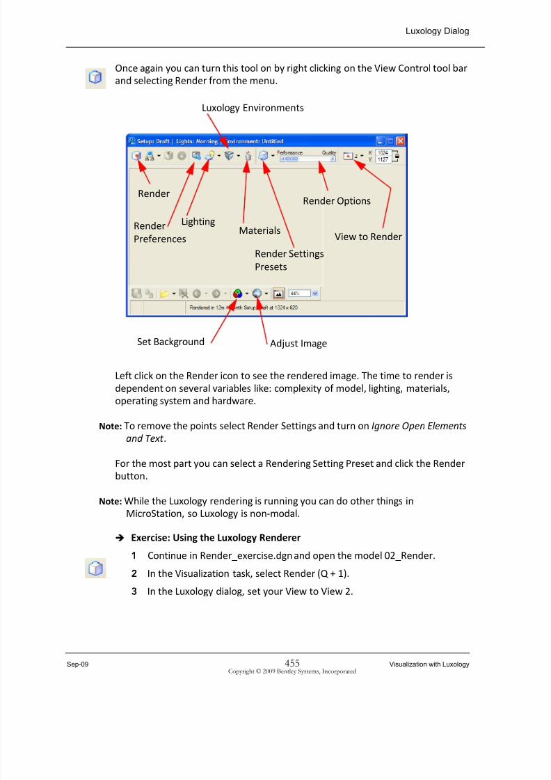
Once again you can turn this tool on by right clicking on the View Control tool bar
and selecting Render from the menu.
Left click on the Render icon to see the rendered image. The time to render is
dependent on several variables like: complexity of model, lighting, materials,
operating system and hardware.
Note: To remove the points select Render Settings and turn on Ignore Open Elements
and Text .
For the most part you can select a Rendering Setting Preset and click the Render
button.
Note: While the Luxology rendering is running you can do other things in
MicroStation, so Luxology is non‐modal.
Exercise: Using the Luxology Renderer
1 Continue in Render_exercise.dgn and open the model 02_Render.
2 In the Visualization task, select Render (Q + 1).
3 In the Luxology dialog, set your View to View 2.
Render
LightingMaterials
Render Options
View to RenderRender
Preferences
Render Settings
Presets
Set Background Adjust Image
Luxology Environments
8/9/2019 SW-1 Viz With Luxology
http://slidepdf.com/reader/full/sw-1-viz-with-luxology 12/62
Visualization with Luxology 456 Sep-09Copyright © 2009 Bentley Systems, Incorporated
Luxology Environments
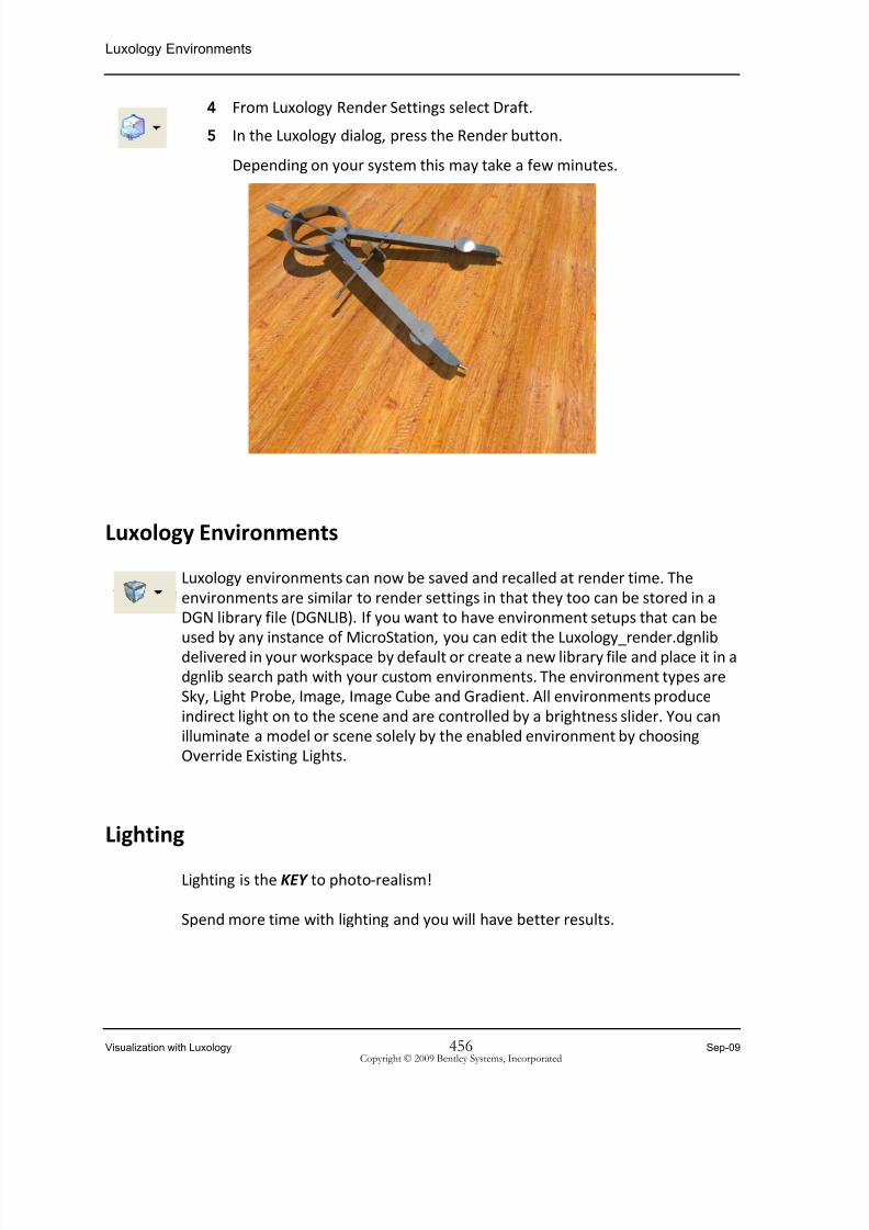
4 From Luxology Render Settings select Draft.
5 In the Luxology dialog, press the Render button.
Depending on your system this may take a few minutes.
Luxology Environments
Luxology environments can now be saved and recalled at render time. The
environments are similar to render settings in that they too can be stored in a
DGN library file (DGNLIB). If you want to have environment setups that can be
used by any instance of MicroStation, you can edit the Luxology_render.dgnlib
delivered in your workspace by default or create a new library file and place it in a
dgnlib search path with your custom environments. The environment types are
Sky, Light Probe, Image, Image Cube and Gradient. All environments produce
indirect light on to the scene and are controlled by a brightness slider. You can
illuminate a model or scene solely by the enabled environment by choosing
Override Existing Lights.
Lighting
Lighting is the KEY to photo‐realism!
Spend more time with lighting and you will have better results.

8/9/2019 SW-1 Viz With Luxology
http://slidepdf.com/reader/full/sw-1-viz-with-luxology 13/62
Sep-09 457 Visualization with LuxologyCopyright © 2009 Bentley Systems, Incorporated
Lighting
Where your goal is to produce realistic images of your models, you can use the
Luxology rendering engine. This takes into account both direct and indirect
lighting, such as reflection of light and refraction. Additionally, it can calculate
diffuse reflections and caustics (such as reflected light, and refraction). For these
two features, in particular, the following points should be kept in mind:
You should use real world working units for your model, and lighting values are
input as lumens.
IES lighting files should be used to correctly display the lighting characteristics of
different lamps, such as halogen lamps, incandescent lamps, or fluorescent tubes.
Care has to be taken when defining materials, to ensure that realistic values are
defined. You should set the display gamma value for your output.
Default
Lighting
Default Lighting consists of a shadow casting light over the viewer’s shoulder,
plus some ambient and a flash. This lighting is ideal for modeling in 3D, as it
always provides very good illumination of a model relative to the observer.
Because Default Lighting is a view attribute, you must enabled it to be used to
illuminate your model.
To use Default Lighting, you must enable it for any view(s) where you want use it.
This is done by clicking the Adjust View Brightness tool on the view border and
turning on the Default Lighting toggle. When the Brightness tool is clicked, you
will see a brightness slider and a toggle for enabling Default Lighting; checking the
option turns on the Default Lighting for the view. The icon on the Adjust View
Brightness tool changes to reflect the current state.
When the Display Mode of a Display Style is Shaded, that is, anything other than
wireframe and
hidden
line,
then
the
hardware
renderer
uses
Default
Lighting
or
the user‐defined lights (Scene Lighting), depending on the Default Lighting view
attribute.

8/9/2019 SW-1 Viz With Luxology
http://slidepdf.com/reader/full/sw-1-viz-with-luxology 14/62
Visualization with Luxology 458 Sep-09Copyright © 2009 Bentley Systems, Incorporated
Lighting
If a Light Setup other than From View is chosen, the Render tool overrides this
view attribute and uses scene lighting.
When using the Render tool, to see the effects of Default Lighting, turn on Default
Lighting for the view you are rendering; make sure that Light Setup: From View is
chosen. To render a view using scene lighting, you can chose any light setup other
than From View, or render a view with Default Lighting off. If you choose Light Setup: From View and enter a data point, the current state of the view attribute
Default Lighting for that view determines which lighting is used.
There are two basic types of lighting that you can control: Global Lighting and
Source Lighting. To open the Light Manager, select the Light icon in the Luxology
Manager.
Global Lighting
Global lighting affects all elements in a model.

8/9/2019 SW-1 Viz With Luxology
http://slidepdf.com/reader/full/sw-1-viz-with-luxology 15/62
Sep-09 459 Visualization with LuxologyCopyright © 2009 Bentley Systems, Incorporated
Lighting
Brightness
There are new settings for control the overall brightness of an image. The
Brightness control are split into two sections: Display Brightness and Global
Illumination Brightness. Both of these have two options:
Brightness Multiplier
Scales all pixels by a specified factor. In the field, set the scale factor to be applied
to the brightness of the pixels for the next rendering.
Adapt to Brightness
Sets the brightness for the middle of the range. In the field, set the intensity (in
lumens) that should be used as the middle of the display range for the next
rendering.
Ambient
Ambient lighting affects every element in the model. It adds lighting equally to all
elements. As you increase the value of Ambient lighting, the amount of contrast
diminishes. Ambient lighting is useful for illuminating surfaces that would not
otherwise receive light. No shadows are cast by Ambient light. Settings for this
light source let you adjust its Lux, Color, and Temperature (in Kelvin or K). One lux
is equal to one lumen per square meter. Essentially, one lumen is the minimum
amount of light the human eye can see. For a full definition please refer to the
glossary.
Flashbulb
Like a flashbulb on a camera, this light source illuminates all elements that are
facing the viewing position or camera. Useful for checking models during
construction, you also can use it to add light to a final image. No shadows are cast
by this light source. Settings in the Global Lighting dialog, let you adjust the Lux,
Color and temperature of the Flashbulb.
Solar
Used to
simulate
lighting
from
the
Sun,
Solar
lighting
has
settings
that
let
you
set
any of the following:
• Latitude, longitude, time and date of the rendering.
• Solar Direction Vectors of the sunlight.

8/9/2019 SW-1 Viz With Luxology
http://slidepdf.com/reader/full/sw-1-viz-with-luxology 16/62
Visualization with Luxology 460 Sep-09Copyright © 2009 Bentley Systems, Incorporated
Lighting
• Azimuth Angle and Altitude Angle of the Sun.
You can input this data manually in the appropriate fields, or you can use dialogs
to select a city from a list or pick a location from a map of the world. These
dialogs are opened by clicking one of the following options in the Location section
of the Global Lighting dialog:
Cities — opens the Location By City dialog from which you can select a city
from the list.
Get Long./Lat. from Google Earth— opens Google Earth. In Google Earth you
can enable View > Grid to display longitude and latitude and View > Sun,
which will show time automatically. With this method, you must still enter the
GMT Offset manually in MicroStation.
Get Long./Lat. from KML file ‐ Allows you to select a KML file to fill in Long./
Lat. from what is stored in that KML file. Again you must fill in the GMT Offset
manually in MicroStation.
Zones —
Opens
the
GMT
Offset
By
Time
Zone
dialog
from
which
you
can
select a time zone.
Optionally, you can turn on Solar Shadows to view the effect of shadows
generated by the Solar lighting (sunlight) when rendering with the Phong or Ray
Trace options. As with other Global light sources, you can specify the Lux, Color
and temperature of the simulated sunlight.
Left image light parameters set for 9:00 AM, middle 12:00 noon and right image 5:00 PM in Philadelphia, USA
Sky Dome
The Sky Dome provides direct illumination and mimics sky lighting.
Using Sky Dome with Shadows enabled can increase the render time significantly.
The Shadow setting of Soft ‐ Coarse (32 samples) is recommended for faster
rendering.
Lux
Displays the value for the sky lighting with the current settings. If the Sun would
be below the horizon, then “No Sun” displays.

8/9/2019 SW-1 Viz With Luxology
http://slidepdf.com/reader/full/sw-1-viz-with-luxology 17/62
Sep-09 461 Visualization with LuxologyCopyright © 2009 Bentley Systems, Incorporated
Lighting
Color type
Option menu that lets you select the type of color used.
• User Defined — Lets you set the color of the sky lighting, via the Color setting,
or automatically via the Temperature setting.
• Physically Based
—
Sky
color
is
computed
based
on
factors
such
as
the
Sun
position, air quality, and cloudiness.
• When illuminated only by sky, different parts of the sky may have different
colors. This can result in different sides of a building having different lighting.
Color
Sets the color of the sky lighting. Clicking on the color swatch opens a color
selector dialog, which is similar to the True Color tab and Color Book tab of the
Active Color dialog.
Temperature
Option menu that lets you assign a color temperature to sky lighting. When a
color is chosen manually, with the Color setting, Temperature is set to Custom.
Shadow
If on, shadows are generated for the added sky lighting. Sharpness of the
shadows is controlled by the option menu.
Exercise: Using Global Lighting tools
1 Continue in Render_exercise.dgn and open the model 06_Global Lighting.
Several settings have been set for you, let’s review them.
2 Open the Luxology dialog (Q + 1).
3 Click on the Luxology Environment Settings.

8/9/2019 SW-1 Viz With Luxology
http://slidepdf.com/reader/full/sw-1-viz-with-luxology 18/62
Visualization with Luxology 462 Sep-09Copyright © 2009 Bentley Systems, Incorporated
Lighting
4 Select the Global Lighting Environment Setup.
Note that Sky has been selected with a Sun Size of 4.
5 Open the Light Manager (W + 1).
You can also open this dialog from inside the Luxology dialog.
6 In the Light Manager, select Solar.
7 In the tool bar across the top select Highlight.
Highlight and
Element
Section
selected.
Warning: You must select the Highlight option in order to see the Sun in the
final render.

8/9/2019 SW-1 Viz With Luxology
http://slidepdf.com/reader/full/sw-1-viz-with-luxology 19/62
Sep-09 463 Visualization with LuxologyCopyright © 2009 Bentley Systems, Incorporated
Lighting
8 Change Temperature to 3200 K Sunrise/Sunset.
9 Change to the current date.
Click on the current date to set the current date.
10 Set Time to 7:00am
11 Select Position by City and choose Phoenix.
You can also choose a City by getting a Latitude and Longitude from
Google Earth or a KML file.
12 Leave all other values at default.
13 In the Luxology dialog, select view to render as View 2 and press Render.
8/9/2019 SW-1 Viz With Luxology
http://slidepdf.com/reader/full/sw-1-viz-with-luxology 20/62
Visualization with Luxology 464 Sep-09Copyright © 2009 Bentley Systems, Incorporated
Lighting
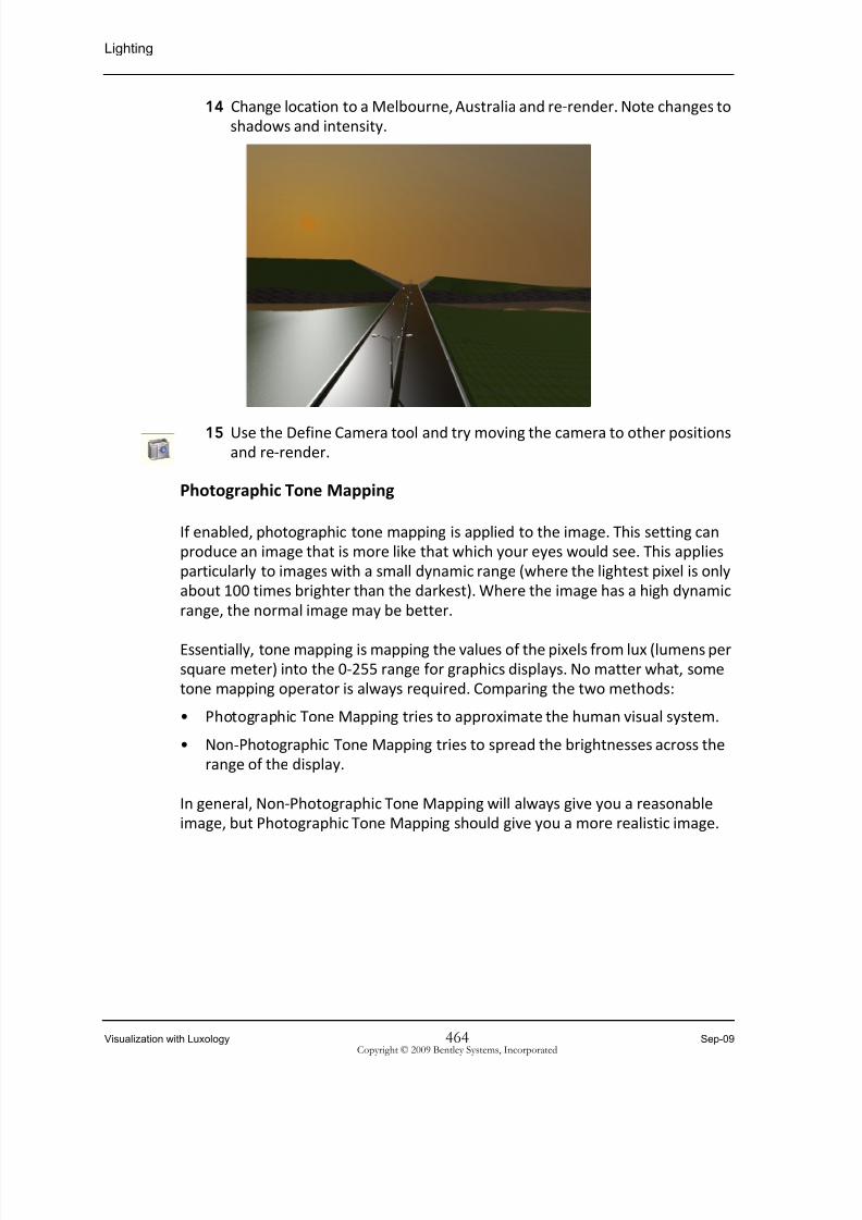
14 Change location to a Melbourne, Australia and re‐render. Note changes to
shadows and intensity.
15 Use the
Define
Camera
tool
and
try
moving
the
camera
to
other
positions
and re‐render.
Photographic Tone Mapping
If enabled, photographic tone mapping is applied to the image. This setting can
produce an image that is more like that which your eyes would see. This applies
particularly to images with a small dynamic range (where the lightest pixel is only
about 100 times brighter than the darkest). Where the image has a high dynamic
range, the normal image may be better.
Essentially, tone
mapping
is
mapping
the
values
of
the
pixels
from
lux
(lumens
per
square meter) into the 0‐255 range for graphics displays. No matter what, some
tone mapping operator is always required. Comparing the two methods:
• Photographic Tone Mapping tries to approximate the human visual system.
• Non‐Photographic Tone Mapping tries to spread the brightnesses across the
range of the display.
In general, Non‐Photographic Tone Mapping will always give you a reasonable
image, but Photographic Tone Mapping should give you a more realistic image.

8/9/2019 SW-1 Viz With Luxology
http://slidepdf.com/reader/full/sw-1-viz-with-luxology 21/62
Sep-09 465 Visualization with LuxologyCopyright © 2009 Bentley Systems, Incorporated
Source Lighting
Source Lighting
Unlike Global Illumination, which is controlled solely from a dialog, Source
lighting consists of light sources in the form of special cells that you place in the
design. This is done with the Define Light tool, which you will look at shortly. First,
a brief
description
of
source
lighting.
Source lighting cells are stored in the cell library lighting.cel, which is accessed
automatically by the Place Light tool. You do not have to attach this cell library
before placing light sources. The Place Light tool has various settings for each
light source type, which you enter prior to placing the light source. The same tool
lets you modify them, if necessary, at a later date. The cells consist of
construction class elements and are placed by default on level Default.
Place Light tool
Source lighting provides a choice of 5 lighting types; Point, Spot, Area, Directional
and Sky Opening. These light sources provide lighting as follows.
Point
Similar to a light globe, point light sources radiate light in all directions, from a
point light source. Shadows can be generated by this light source in Ray Trace
rendering only; they are not supported by Phong rendering.

8/9/2019 SW-1 Viz With Luxology
http://slidepdf.com/reader/full/sw-1-viz-with-luxology 22/62
Visualization with Luxology 466 Sep-09Copyright © 2009 Bentley Systems, Incorporated
Source Lighting
Spot
Directional light source that behaves similar to a flashlight. Spot Lights have a
conical beam. This can be defined to taper off to zero at the edge of the beam.
You can define the Cone Angle for the beam and a Delta Angle through which the
beam
reduces
from
full
intensity
to
zero.
Shadows
can
be
generated
by
this
light
source for Phong and RayTrace rendering.
Area
Created from existing polygons in the design, these light sources are useful for
simulating fluorescent lighting, for example.
Directional
Directional light source that produces parallel light rays throughout the design,
similar to sunlight. It does not matter where in the model that you place one of

8/9/2019 SW-1 Viz With Luxology
http://slidepdf.com/reader/full/sw-1-viz-with-luxology 23/62
8/9/2019 SW-1 Viz With Luxology
http://slidepdf.com/reader/full/sw-1-viz-with-luxology 24/62
Visualization with Luxology 468 Sep-09Copyright © 2009 Bentley Systems, Incorporated
Source Lighting
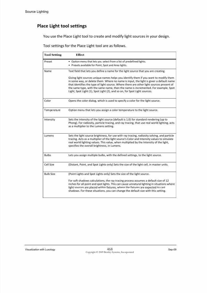
Place Light tool settings
You use the Place Light tool to create and modify light sources in your design.
Tool settings for the Place Light tool are as follows.
Tool Setting Effect
Preset • Option menu that lets you select from a list of predefined lights.
• Presets available for Point, Spot and Area lights.
Name Text field that lets you define a name for the light source that you are creating.
Giving light sources unique names helps you identify them if you want to modify them
in some way, or delete them. Where no name is input, the light is given a default name
that identifies the type of light source. Where there are other light sources present of the same type, with the same name, then the name is incremented. For example, Spot Light, Spot Light (1), Spot Light (2), and so on, for Spot Light sources.
Color Opens the color dialog, which is used to specify a color for the light source.
Temperature Option menu that lets you assign a color temperature to the light source.
Intensity Sets the intensity of the light source (default is 1.0) for standard rendering (up to
Phong). For radiosity, particle tracing, and ray tracing, that use real world lighting, acts
as a multiplier to the Lumens setting.
Lumens Sets the light source brightness, for use with ray tracing, radiosity solving, and particle
tracing. Acts as a multiplier of the light source's Color and Intensity values to simulate
real world lighting values. This value, when multiplied by the Intensity of the light, specifies the overall brightness, in Lumens.
Bulbs Lets you
assign
multiple
bulbs,
with
the
defined
settings,
to
the
light
source.
Cell Size (Distant, Point, and Spot Lights only) Sets the size of the light cell, in master units.
Bulb Size (Point Lights and Spot Lights only) Sets the size of the light source.
For soft shadows calculations, the ray tracing process assumes a default size of 12
inches for all point and spot lights. This can cause unnatural lighting in situations where
light sources are placed within fixtures, where the fixtures are expected to cast shadows. For these situations, you can change the default size with this setting.
8/9/2019 SW-1 Viz With Luxology
http://slidepdf.com/reader/full/sw-1-viz-with-luxology 25/62
Sep-09 469 Visualization with LuxologyCopyright © 2009 Bentley Systems, Incorporated
Source Lighting
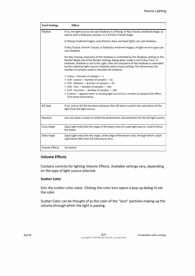
Volume Effects
Contains controls for lighting Volume Effects. Available settings vary, depending
on the type of light source selected.
Scatter Color
Sets the scatter color value. Clicking the color icon opens a pop‐up dialog to set
the
color.
Scatter Color can be thought of as the color of the “dust” particles making up the
volume through which the light is passing.
Shadow If on, the light source can cast shadows in a Phong, or Ray Traced, rendered image, as
well as with a Radiosity solution, or a Particle Traced image.
In Phong rendered images, only Distant, Area, and Spot lights can cast shadows.
In Ray
Traced,
Particle
Traced,
or
Radiosity
rendered
images,
all
light
source
types
can
cast shadows.
For Ray Tracing, sharpness of the shadows is controlled by the Shadows setting on the
Render Mode tab of the Render Settings dialog when mode is set to Ray Trace. If, however, Shadows is set to Per Light, then the sharpness of the shadows is controlled
by the individual light source's Shadow option menu setting. This determines the
number of samples used to calculate the shadows.
• Sharp — Number of samples — 1
• Soft ‐ Coarse — Number of samples — 16
• Soft ‐ Medium — Number of samples — 64
• Soft ‐ Fine — Number of samples — 160
• Soft ‐ Very Fine — Number of samples — 256
• Custom — Appears when an existing light source has a number of samples that differs
from those
listed
above.
IES Data If on, and an IES file has been selected, then IES data is used in the calculation of the
light from the light source.
Rotation Lets you enter a value to rotate the photometric characteristics for the IES light source.
Cone Angle (Spot Light only) Sets the angle of the beam cone of a spot light source. Used to focus
the beam.
Delta Angle (Spot Light only) Sets the angle, at the edge of the beam cone, through which a Spot Light beam falls from full intensity to zero.
Volume Effects See below
Tool Setting Effect

8/9/2019 SW-1 Viz With Luxology
http://slidepdf.com/reader/full/sw-1-viz-with-luxology 26/62
Visualization with Luxology 470 Sep-09Copyright © 2009 Bentley Systems, Incorporated
Source Lighting
Scatter Color RGB values set to 94,94,94 (left) and 40,50,156 (right)
Samples
Controls the accuracy of the volumetric effect underneath shadowing objects.
Increasing the samples value improves the accuracy.
Samples set to 40 (left) and 200 (right)
Height
(Applies to Spot Lights, Directional, and Solar lights only) Sets the height in
working units, of the scattering effect in the volume associated with the light.
Height set to 2 meters (left) and 0.5 meters (right)
Radius
(Applies to Point, Directional, and Solar lights only)
For Solar and Directional lights, Radius defines a cylinder radius. This, combined
with the height, creates the volume through which scattering occurs.
For point lights, Radius defines the radius of the sphere for the scattering volume.
Base
(Applies to Spot lights only) Defines the offset from the spotlight at which the
scattering can
occur.
Base set to 0 meters (left) and 0.2 meters (right)
Scattering
Controls the amount of light scattering which occurs inside the volume. Higher
values result in more scattering.
Scattering set to 10% (left) and 80% (right)
Density
Sets the density for the volumetric effect. Higher values will make the volume
thicker and more opaque.

8/9/2019 SW-1 Viz With Luxology
http://slidepdf.com/reader/full/sw-1-viz-with-luxology 27/62
Sep-09 471 Visualization with LuxologyCopyright © 2009 Bentley Systems, Incorporated
Source Lighting
Density set to 10% (left) and 80% (right)
Attenuation
Controls the amount of attenuation of the effect. A value of 0% gives a natural fall
off and as the value increases the fall off becomes greater.
Attenuation set to 0% (left) and 50% (right).
Exercise: Place an Area light source as a fluorescent ceiling light
1 Continuing in Render_exercise.dgn, open the model 07_Source Lighting.
View 2 is a camera view that has been set up for rendering. Views 1, 3 and
4 have been set up to simplify adding the light sources.
2 From the View Border or View Attributes make View 2’s Display Style set
to Smooth with Shadows.
Currently, the
Light
Manager
has
Ambient
and
Flashbulb
enabled
for
illuminating the scene.
3 From the Visualization task select Light Manager (W + 1).
4 Enable the Solar light in the Light Manager dialog with the following
settings:
Intensity: 15
Shadow: Sharp
Date: Current Date
Time: 09:30
AM
City: Phoenix
Note: You can change the Time and watch the light coming in from the
window move in VIew 2.
5 Select Place Light (W + 2) with the following tool settings:
Name: Halogen1
Preset: halogen 250W Bulb
Bulbs:
2Shadow : Soft‐Fine

8/9/2019 SW-1 Viz With Luxology
http://slidepdf.com/reader/full/sw-1-viz-with-luxology 28/62
Visualization with Luxology 472 Sep-09Copyright © 2009 Bentley Systems, Incorporated
Source Lighting
6 In View 4, identify the block element inside the overhead fluorescent
light, and indicate the downward direction. You can confirm the direction
in the Front view.
7 Repeat step 5 for the second overhead light and name it Halogen2.
Note: Light Direction can be changed at any time by selecting the light source using
the Element selection tool and adjusting the light target handle or by enabling
the Highlight tool in the Light Manager and selecting the light source name.
8 Select the Render tool (Q + 1).
9 From Luxology Environment Settings select Render_exercise.
10 With Draft Luxology Render Settings and render View 2.
11 Use the Adjust Images Settings tool to adjust Brightness.
12 Try various light settings. Disable all lights, change colors, Presets, Date,
and custom Lumen settings.
Block to Convertto Area Light

8/9/2019 SW-1 Viz With Luxology
http://slidepdf.com/reader/full/sw-1-viz-with-luxology 29/62
Sep-09 473 Visualization with LuxologyCopyright © 2009 Bentley Systems, Incorporated
Materials
When you placed the light source, you gave it a name. If no name was given then
the system would generate a default name, Area Light. Any additional point lights
would default to Area Light(1), Area Light (2), and so on.
Naming light cells can help you later if you want to edit them. Using the Place
Light tool, you don’t need to have light source cells displayed in a view, you can
simply select them from the list.
Point light sources radiate light in all directions, you do not have to consider
direction. With Spot Light lighting, a directional lighting source, you must define
the direction in which the light is shining.
Fences and Rendering
Using a fence lets you try numerous iterations of light settings without waiting for
entire scene to render. After you are satisfied with your settings then render the
entire
scene.
Materials
Materials allow you to add realistic imagery to surfaces, like wood, marble, glass,
etc. Luxology allows for many types of formats, like JPG or TIF or specialized
Luxology materials to add Fur, Displacement Maps or 3D materials.
By default, Luxology rendering assumes that each design file surface is made of a
material with
a smooth
shiny
surface,
such
as
plastic.
Material
definitions
let
you
specify that an element is water or wood or brickwork. When rendered, instead
of seeing the plastic element, you see the specified material. Each material
definition can include a pattern map and/or a bump map, as well as other settings
determining the finish and transparency/translucency of the material plus much
more. Pattern maps and bump maps are image files that are applied to surfaces
during the rendering process.
Material definitions and assignments can be separated into two distinct
categories — local and external. By default, materials are local and saved in
palettes with the DGN file, while external materials require external material
assignment table
(.mat)
and
material
palette
(.pal)
files
to
be
present
during
rendering. Options in the Material Editor dialog's Table menu let you convert or
export local materials to external files.
8/9/2019 SW-1 Viz With Luxology
http://slidepdf.com/reader/full/sw-1-viz-with-luxology 30/62
Visualization with Luxology 474 Sep-09Copyright © 2009 Bentley Systems, Incorporated
Materials
Where required, you can access local palettes and their materials that are stored
in other DGN files.
Material definitions — attributes related to color, texture, opacity (transparency),
and finish — are created and stored in material palettes. For external materials,
these are palette (.pal) files and always must be present when applying materials,
or rendering. For local materials, the external palette file is required only the first time that you access a material. By default, it is then stored in the DGN file.
Many sample material definitions are supplied with MicroStation. If you do not
plan to create your own material definitions, but want to apply existing material
definitions to elements, see the Apply Material tool.
Pattern maps
A pattern
map
is
an
image
file
that
is
applied
to
an
element.
You
can
think
of
this
in terms of wall‐papering a wall. When you render an element that has a pattern
map applied to it, instead of seeing the element (wall) you see the pattern map
(wall‐paper). MicroStation provides a large range of image files, in JPG and TIF
format, that can be used for pattern maps. These are stored in the
…\Workspace\system\materials\pattern folder. Additionally, you can use your
own image files as pattern maps.
Bump maps
Like pattern
maps,
a bump
map
is
an
image
file
that
is
applied
to
an
element.
Where it differs from a pattern map is that a bump map applies roughness or
texture to a rendered surface. While it is not mandatory for bump map images to
be grey‐scale, quite often they are. MicroStation uses the contrast in the bump
map image to calculate texture, or bumps, in the rendered image. As part of the
material definition, you can vary the height of these bumps. This lets you use the
same bump map image file, for example, to create cast metal from very rough‐
cast through to nearly smooth.
Materials stored in DGN
By default, all palettes and their materials now are stored locally in the DGN.
Where required, you still can convert or export the materials and palettes to
external files.

8/9/2019 SW-1 Viz With Luxology
http://slidepdf.com/reader/full/sw-1-viz-with-luxology 31/62
Sep-09 475 Visualization with LuxologyCopyright © 2009 Bentley Systems, Incorporated
Materials
Material palettes can be used from any DGN or DGN Library. You can review:
C:\Documents and Settings\All Users\Application
Data\Bentley\MicroStation\WorkSpace\System\dgnlib
for more information on how to do this.
You can access material palettes from any DGN or DGN Library file. When you
select Palette > Open from the Material Editor, you can select a DGN file to
display the palettes contained within it.
Material tables
When you assign materials from a palette file to an element in a design, the
assignment is stored in a material table. By default, material tables are given the
same name as the design file but have a .mat suffix. Also, by default, material
tables are
saved
in
the
same
folder
as
the
design
file.
You
can
save
them
with
another name and in another folder, if you wish.
Material Tables can be stored in the DGN file itself so no external file is needed.
Hint: Using Element Selection is a quick way to find and change material assignments
and attachments.
Additional Map Types
Clear Coat
‐The
clear
coat
map
changes
the
perceived
thickness
of
the
clear
coat
lacquer effect.

8/9/2019 SW-1 Viz With Luxology
http://slidepdf.com/reader/full/sw-1-viz-with-luxology 32/62
Visualization with Luxology 476 Sep-09Copyright © 2009 Bentley Systems, Incorporated
Materials
Diffuse ‐ A diffuse map can be used in conjunction with a pattern map to give
more contrast to the diffuse reflection.
Glow ‐ The pixels in a glow map specify the fraction of glow emitted by the
surface at that point up to 100%.
Opacity ‐ Maps for Opacity vary the transparency across the material with the
darker parts
of
the
map
being
more
transparent.
Specular Color ‐ If a surface is reflective, then the specular color map is also used
as the reflect color.
Left: Specular Color Map, Right: Reflective

8/9/2019 SW-1 Viz With Luxology
http://slidepdf.com/reader/full/sw-1-viz-with-luxology 33/62
Sep-09 477 Visualization with LuxologyCopyright © 2009 Bentley Systems, Incorporated
Materials
Transparent Color ‐ A transparent color map can be used to vary the transparent
color of a surface.
Translucent Color ‐ A translucency color map can be used to vary the translucent
color of a surface.
Displacement ‐ When using displacement maps the displacement procedure
creates additional geometry in the scene at render time. This means that this new
geometry will
be
added
to
the
calculation
of
light,
materials
and
visibility.
Displacing geometry in a scene can increase the render time significantly
especially if its in high quantity.
Displacement map on a smooth sphere

8/9/2019 SW-1 Viz With Luxology
http://slidepdf.com/reader/full/sw-1-viz-with-luxology 34/62

8/9/2019 SW-1 Viz With Luxology
http://slidepdf.com/reader/full/sw-1-viz-with-luxology 35/62
Sep-09 479 Visualization with LuxologyCopyright © 2009 Bentley Systems, Incorporated
Materials
When you select the Apply Material tool, the Apply Material tool settings opens.
From this dialog, you can load palette files, apply materials or open the Define
Materials dialog.
From left to right, the icons across the top of the Apply Material tool’s dialog let
you select from:
• Assign by Level/Color — to attach a material to elements of a particular
color(s) on a particular level(s) in the model.
• Remove Assignment — to remove an existing level/color material assignment
from elements
in
the
model.
• Attach — to “physically” attach a material definition to an element, or a face
of a solid, in the model. This setting take precedence over level/color
assignments.
• Remove Attachment — remove a material attachment from an element or
the face of a solid in the model.
• Query — to check for a material assignment to an element in the model. With
AccuSnap active, you simply hover the pointer over the element being
queried, and a tool tip displays the assignment or attachment information.
Working with Materials
To apply materials you can Assign them to a Level and Color combination or
Attach them to an individual face of a 3D object.
Exercise: Assigning a Material
1 Continue in Rendering_exercise.dgn.
2 Open the Model 03_Materials.
3 In
the
Visualization
task
select
Render
(Q
+
1).4 Click on the Material icon in the Luxology Manager.

8/9/2019 SW-1 Viz With Luxology
http://slidepdf.com/reader/full/sw-1-viz-with-luxology 36/62
Visualization with Luxology 480 Sep-09Copyright © 2009 Bentley Systems, Incorporated
Materials
This opens the Material Editor.
5 Click on Open Palette or select the menu item Palette > Open.
6 Select the Luxology_Presets.pal [Bentley_Materials.dgnlib].
You now have access to all materials in that palette.

8/9/2019 SW-1 Viz With Luxology
http://slidepdf.com/reader/full/sw-1-viz-with-luxology 37/62
Sep-09 481 Visualization with LuxologyCopyright © 2009 Bentley Systems, Incorporated
Materials
7 Right click on Fabric ‐ Velvet and select Assign.
8 Left click once on the cushion of the chair and left click again on nothing
(empty space).
The second left click is to Accept the assignment of the material.
9 From the same palette select the material: Metal_Chrome and assign to a
leg of the chair.
10 From the Material Editor dialog, select Palette > Open.
11 Select the carpet&fabric.pal [Bentley_Materials.dgnlib] palette.
12 Select the material: carpet_52
13 Right‐click and Assign carpet_52 to the block representing the floor plane.
14 Select the Render tool.
15 In the Luxology dialog, select Luxology Render Settings and choose Draft.

8/9/2019 SW-1 Viz With Luxology
http://slidepdf.com/reader/full/sw-1-viz-with-luxology 38/62
Visualization with Luxology 482 Sep-09Copyright © 2009 Bentley Systems, Incorporated
Materials
16 Render the model by selecting Render in the Luxology Manager.
17 Explore other materials (for example, Black Leather from carpets&fabric)
and try them out. You can Remove Assignment, by using the right‐click
menu on a specific material.
Exercise: Attaching a different material to faces of a solid
1 Continuing in Render_exercise.dgn, open the model 04_Materials 2.
2 In the Visualization task select Apply Material (A + 1).
3 Click the Attach icon in the Apply Material tool setting icon bar.
4 Click the Open palette icon in the tool settings.
5 Select the
palette:
blocks&bricks.pal
[Bentley_Materials.dgnlib].
6 From the Materials list, select brick back alley.

8/9/2019 SW-1 Viz With Luxology
http://slidepdf.com/reader/full/sw-1-viz-with-luxology 39/62

8/9/2019 SW-1 Viz With Luxology
http://slidepdf.com/reader/full/sw-1-viz-with-luxology 40/62
Visualization with Luxology 484 Sep-09Copyright © 2009 Bentley Systems, Incorporated
Materials
11 In View 2, identify the solid and select the table top and side faces.
12 Use the Render tool with Draft Luxology Render Setting and render View
4.
Multi‐Layered Materials
You can create materials that consist of multiple layers of pattern maps, bump
maps, procedures, gradients, and/or operations (tint or gamma setting). AN
example might be showing tire tracks on a road or graffiti on a wall or dirt on a
surface.
New mapping options let you apply an image, gradient, procedure, or Operation
(Tint or Gamma) to the Color, Translucency, Specular, Reflect, Finish, Opacity, and
Bump channels. As well, each channel can be multi‐layered. The Material Editor
lets you access the mapping option via icons for each channel.
8/9/2019 SW-1 Viz With Luxology
http://slidepdf.com/reader/full/sw-1-viz-with-luxology 41/62
Sep-09 485 Visualization with LuxologyCopyright © 2009 Bentley Systems, Incorporated
Materials
You can define the way that the pattern/bump maps are blended and you can
assign a value for opacity, to allow one map to be seen through another.
Adding layers of pattern maps, lets you create more complex materials. For
example, you can create a brick wall that includes 1 or more signs, or have a
material with partial opacity.
You can add layers to your material definitions, with various blend modes. The
layers can be toggled as required.
Warning: Multi‐layered materials are not backward compatible with MicroStation V8 XM
Edition v8.9.2 and earlier.
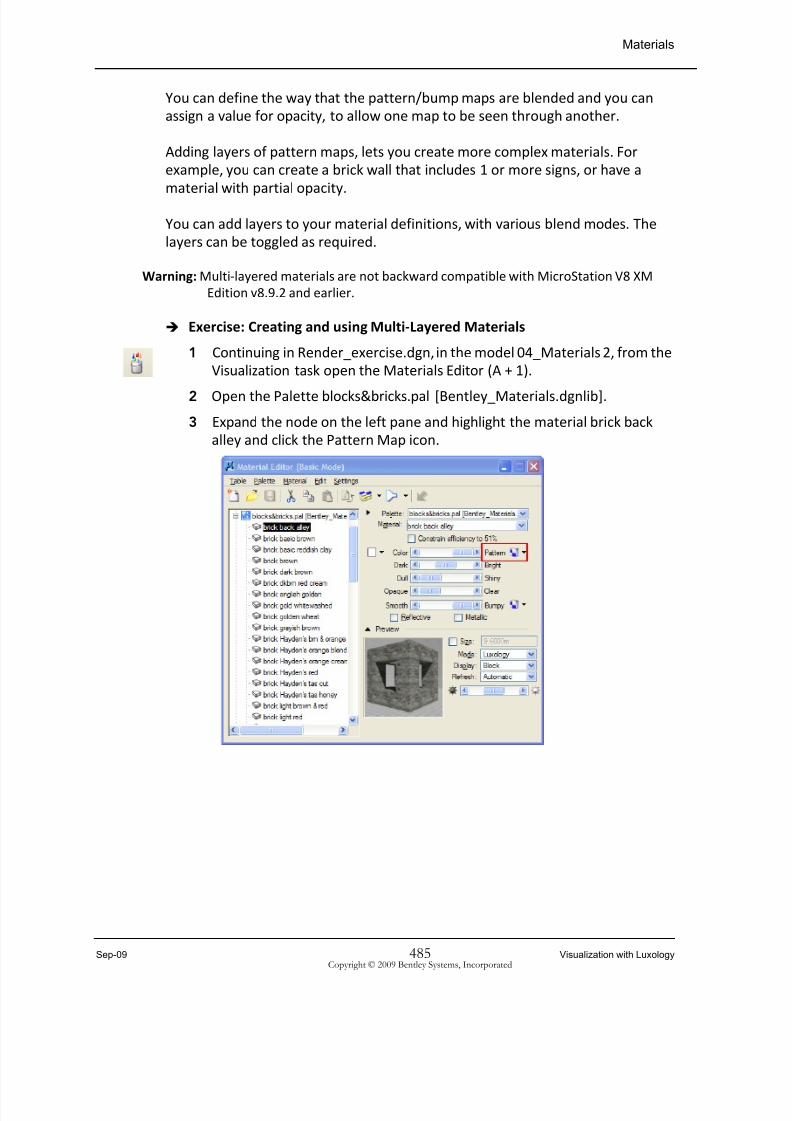
Exercise: Creating and using Multi‐Layered Materials
1 Continuing in Render_exercise.dgn, in the model 04_Materials 2, from the
Visualization task open the Materials Editor (A + 1).
2 Open the
Palette
blocks&bricks.pal
[Bentley_Materials.dgnlib].
3 Expand the node on the left pane and highlight the material brick back
alley and click the Pattern Map icon.

8/9/2019 SW-1 Viz With Luxology
http://slidepdf.com/reader/full/sw-1-viz-with-luxology 42/62

8/9/2019 SW-1 Viz With Luxology
http://slidepdf.com/reader/full/sw-1-viz-with-luxology 43/62
Sep-09 487 Visualization with LuxologyCopyright © 2009 Bentley Systems, Incorporated
Projection modes for Pattern/Bump Maps
6 In View 4 zoom in on the right side of front table and Render using Draft
Luxology Render Settings.
Smooth Display Style of View 4
Projection modes for Pattern/Bump Maps
Projection modes are assigned to elements, rather than the material. This lets
you use
the
same
material
with
various
projection
modes
depending
on
the
geometry.

8/9/2019 SW-1 Viz With Luxology
http://slidepdf.com/reader/full/sw-1-viz-with-luxology 44/62
Visualization with Luxology 488 Sep-09Copyright © 2009 Bentley Systems, Incorporated
Projection modes for Pattern/Bump Maps
Control projection modes using the Materials task.
Projection modes for materials
Several projection modes are available:
• Directional Drape ‐ Mapping is applied relative to the direction specified by
the Orientation setting
• Cubic ‐ Mapping is applied in a cubic fashion relative to the geometry.
• Spherical ‐ Mapping is applied in a spherical fashion relative to the geometry.
• Cylindrical ‐Mapping is applied in a cylindrical fashion relative to the
geometry.
Warning: Material
projection
modes
are
not
backward
‐compatible
with
MicroStation
V8
XM
Edition v8.9.2 and earlier.
Tools for controlling Material Projections
The Materials task adds 5 tools for handling material projections.
Exercise: Using Material Projections
1 Continuing in Render_exercise.dgn, open the model 05_Projections.
2 Assign the
material
‐Brick
Aged
to
the
sphere.

8/9/2019 SW-1 Viz With Luxology
http://slidepdf.com/reader/full/sw-1-viz-with-luxology 45/62
Sep-09 489 Visualization with LuxologyCopyright © 2009 Bentley Systems, Incorporated
Projection modes for Pattern/Bump Maps
3 Render to see the results.
4 Select Attach Projection (S + 1) with the following tool setting:
Method: Spherical
5 Enter a data point on the sphere.
6 Render to see result.

8/9/2019 SW-1 Viz With Luxology
http://slidepdf.com/reader/full/sw-1-viz-with-luxology 46/62
Visualization with Luxology 490 Sep-09Copyright © 2009 Bentley Systems, Incorporated
Projection modes for Pattern/Bump Maps
7 Repeat with the cylinder and Slab.
8 Select the Edit Projection tool (S + 2) with the following settings:
Select: Scale Projection
Attach To: Element
Mapping: Cubic
9 Click on the Arrows to select a variety of scale directions.
10 Us
the
Remove
Projection
tool
(S
+
5)
and
remove
the
projection
from
the
slab.
11 Make a Copy (3 + 1) of the slab and place it on the side of the original slab.
12 Attach a new projection (S + 1) to both of the slabs.
13 Edit the Projection scale of one of the slabs.
14 Select the Match Projection tool (S + 3) with the following settings:
Enable: Projection Scale

8/9/2019 SW-1 Viz With Luxology
http://slidepdf.com/reader/full/sw-1-viz-with-luxology 47/62
Sep-09 491 Visualization with LuxologyCopyright © 2009 Bentley Systems, Incorporated
Projection modes for Pattern/Bump Maps
15 Select the slab that the projection scale was modified then select the
other slab to match this project on this slab.
Ambient Occlusion
An additional rendering method is Ambient Occlusion, which is found from
Luxology Render Settings.
Ambient occlusion
is
a shading
method
used
in
3D
computer
graphics
which
helps
add realism to local reflection models by taking into account attenuation of light
due to occlusion. Ambient occlusion attempts to approximate the way light
radiates in real life, especially off what are normally considered non‐reflective
surfaces.
Ray Tracing
Ray Tracing is still available from Luxology Render Settings.
8/9/2019 SW-1 Viz With Luxology
http://slidepdf.com/reader/full/sw-1-viz-with-luxology 48/62
Visualization with Luxology 492 Sep-09Copyright © 2009 Bentley Systems, Incorporated
Output of Imagery
Output of Imagery
There are many ways to share your computer graphics imagery (CGI). One way is
to create a 3D PDF of your rendered model (see next module), another is to Save
an image to disk.
Save Image
Now that you can set up and create rendered images of your models, you might
want to save one or more of them and impress your friends and clients by
sending them a file containing the image. You can quickly save MicroStation
images using the Save option in the Utilities > Image menu.
You have many choices when saving your images, such as file format, resolution
and type of shading. As well as being able to save your images, MicroStation
provides a viewing
facility
and
a way
to
perform
limited
modifications.
There are many variables that you can adjust when saving images, however, you
will find that most remain consistent once you begin to integrate images into
your workflow.
These tools are found on the Utilities > Image menu. In addition to these basics
you can also convert images, capture the screen as an image and save an image
using multiple computers to speed up the processing time.

8/9/2019 SW-1 Viz With Luxology
http://slidepdf.com/reader/full/sw-1-viz-with-luxology 49/62
Sep-09 493 Visualization with LuxologyCopyright © 2009 Bentley Systems, Incorporated
Output of Imagery
To save an image to disk you can use Utilities > Image > Save.
Here you can choose several things, including: Format, DPI and Render Mode. For
a quick test choose Luxology from Render Mode.
Saving a rendered image
To save
an
image,
select
Utilities
> Image
> Save,
which
opens
the
Save
Image
dialog.
• View controls which view will be rendered.
• Format controls the type of file format in which the image file will be saved.
MicroStation supports a wide variety of file formats including JPG, TIF, TGA,
Postscript, PCX and others.
• Compression selects the type of file compression for those formats that allow
it. For example, if you select JPEG then you have the option of choosing High
Loss (high compression) through to Minimum Loss (high quality).
• Mode lets
you
select
the
bit
depth
of
the
image
or
grey
scale.
• Shading lets you select which type of shading to use. For high quality images
that cast shadows, select RayTrace shading mode.
• Shading Types lets you select between Normal, Antialias and Stereo.

8/9/2019 SW-1 Viz With Luxology
http://slidepdf.com/reader/full/sw-1-viz-with-luxology 50/62
Visualization with Luxology 494 Sep-09Copyright © 2009 Bentley Systems, Incorporated
Distributed Rendering
• Action is set to Ray Trace, Radiosity, or Particle Trace only. Sets the rendering
action to be performed.
• Resolution controls how large an image you produce, in terms of pixels.
Thought should be given to displaying the saved image. In order to display the
saved image, you must have enough RAM on your video card to hold the
image. This
depends
also
on
what
bit
depth
(24
bit
or
8 bit)
you
select
in
Mode.
When one of the Resolution values (X or Y) is adjusted the other updates to
maintain the view aspect ratio. Using higher resolution allows you to have
more pixels to work with, hence a finer quality image.
• Gamma Correction controls the white content of an image. The values range
from 0.10 to 3.00. A value of 0.10 is very dark while 3.00 is very bright.
Image Size lets you control the output size of the image in pixels, or unit as well as
how many dots per inch are recorded.
Banded Rendering allows for an image to be broken up into strips or bands for
network rendering.
Distributed Rendering lets you process an image using 2 or more PCs networked
together.
After specifying the settings for your image, you can save the image with a unique
file name and place it on your hard drive. The default location in which
MicroStation stores image files is the out directory, such as
…\Workspace\projects\examples\General\out.
Viewing a saved image
MicroStation has a viewing utility that lets you view your saved rendered images
and perform a number of editing and manipulation operations.
To view a rendered image, from within MicroStation, select Utilities > Image >
Display.
Distributed Rendering
You can use several machines to do one rendering or animation by using
Distributed Rendering. Distributed Rendering now is included and does not have

8/9/2019 SW-1 Viz With Luxology
http://slidepdf.com/reader/full/sw-1-viz-with-luxology 51/62
Sep-09 495 Visualization with LuxologyCopyright © 2009 Bentley Systems, Incorporated
Distributed Rendering
to be downloaded as a separate package. Its basic requirement is that all
processors taking part in the rendering have access to all the DGN, texture, RPC,
and raster files to be used in the rendering. It is also necessary that all processors
taking part in the rendering have access to the output path.
Simplified setup
for
Distributed
Rendering
Setting up this new version of Distributed Rendering is simple and it does not
require any external database server as was required previously. To use
Distributed Rendering, you must first launch the Distributed Processing Controller
from the MicroStation start menu.
The first time that you start the controller, you are prompted to define your
Shared (probably server) Directory. This determines where Distributed Rendering
stores the information it needs to configure your controller and pass data back
and forth between multiple machines. All machines that will participate in the
rendering
How to set up Distributed Rendering
1. From the Start menu, select Bentley > MicroStation V8i > Process Controller for
Distributed Rendering.
The Configuration Settings dialog opens.
2. To select a Shared directory, click the button to the right of the field.
3. Select a shared folder and click OK.
4. Click OK.
5. When Distributed Rendering is available, the Bentley Distributed Processing
Scheduler icon appears in the System tray.

8/9/2019 SW-1 Viz With Luxology
http://slidepdf.com/reader/full/sw-1-viz-with-luxology 52/62
Visualization with Luxology 496 Sep-09Copyright © 2009 Bentley Systems, Incorporated
Visualization Glossary
Distributed Rendering Related dialogs
The Scheduler is accessed by right‐clicking the Process Controller tray icon and
choosing Open Scheduler. The Job Monitor is accessed by right‐clicking the
Process Controller tray icon and choosing Open Job Monitor.
Scheduler
The Scheduler dialog is used to schedule times that your system is available for
contributing to processing images.
Job Monitor
The Job Monitor dialog displays the progress of your distributed rendering tasks.
Visualization Glossary
This glossary defines visualization terms used with MicroStation.
actor
In an animation sequence, an element(s) that are scripted to move or rotate in a
controlled manner. Created as a cell.
adaptive subdivision
Process within radiosity solving that dynamically subdivides a surface element
mesh along shadow boundaries, resulting in more accurate and detailed shading.
aliasing
Source of several common computer graphics artifacts such as jagged lines,
missing objects, and jerky motion in animation. In signal processing terms,
aliasing is caused by the under‐sampling of a signal, resulting in some high‐
frequency components of the signal assuming the alias (or false identity) of the
low frequency components, and mixing together in such a way that they can no
longer be
distinguished
properly.

8/9/2019 SW-1 Viz With Luxology
http://slidepdf.com/reader/full/sw-1-viz-with-luxology 53/62
Sep-09 497 Visualization with LuxologyCopyright © 2009 Bentley Systems, Incorporated
Visualization Glossary
ambient light
Imaginary light that is presumed to strike every point on a surface with equal
intensity. Used to approximate the large‐scale effects of diffuse inter‐reflections,
a phenomenon not usually accounted for by most lighting methods. Ambient
light should be turned off when using particle tracing or radiosity solving, both of
which take into account the diffuse reflection of light between surfaces.
animation camera
Actor that is scripted to designate a viewing position, orientation, and
perspective for animation.
animation settings file
File (“.asf”) that contains design and rendering settings while recording an
animation sequence. Particularly useful for collaborative recording of animation
scripts on
networked
systems
or
continuing
disrupted
recordings.
anisotropy
Is the property of being directionally dependent, as opposed to isotropy, which
means homogeneity in all directions. It can be defined as a difference in a
physical property (absorbance, refractive index, density, etc.) for some material
when measured along different axes.
antialiasing
Special rendering
processing
to
remove
or
limit
the
appearance
of
aliasing
artifacts in an image or an animation sequence. See also sample.
area light source
Light source created from a shape element. This type of light source casts softer,
more natural shadows than a Point light source.
camera
Imaginary entity that specifies a scene's viewing position, orientation, and
perspective. See
also
animation
camera.

8/9/2019 SW-1 Viz With Luxology
http://slidepdf.com/reader/full/sw-1-viz-with-luxology 54/62

8/9/2019 SW-1 Viz With Luxology
http://slidepdf.com/reader/full/sw-1-viz-with-luxology 55/62
Sep-09 499 Visualization with LuxologyCopyright © 2009 Bentley Systems, Incorporated
Visualization Glossary
elevate
To move the view cone, linearly, in a vertical direction.
environment cube
Imaginary cube
surrounding
the
entire
design,
on
which
images
are
applied
as
environment maps.
environment
Image file representing the projection of a 3D environment onto a 2D surface
from a specific point of view. A map set of these files can be applied to the six
faces of the environment cube that surrounds a design (or environment). An
environment map is not directly visible in the view, but is seen only when
reflected or transmitted by surfaces in the model to which material
characteristics are applied.
field rendering
Animation script recording technique that results in frames that consist of two
fields each (one for the even numbered scan lines and one for the odd‐numbered
scan lines). Used to improve playback on NTSC and PAL video display systems that
employ interlaced display.
focal point
The point at which initially collimated (parallel) rays of light meet after passing
through a convex
lens,
or
reflecting
from
a concave
mirror.
frame
Single rendered image that is part of a series of rendered images that make up an
animation sequence.
frame number
Identifies a frame's relative position in an animation sequence. Since the speed of
an animation sequence (expressed in frames per second) is constant throughout
the animation,
frame
numbers
can
also
be
thought
of
as
points
in
time.
Therefore, fractional frame numbers can be specified in script entries.

8/9/2019 SW-1 Viz With Luxology
http://slidepdf.com/reader/full/sw-1-viz-with-luxology 56/62
Visualization with Luxology 500 Sep-09Copyright © 2009 Bentley Systems, Incorporated
Visualization Glossary
Fresnel effects
Effect of the angle of view on the reflectivity and transparency of a surface. For
example, a window appears more reflective than transparent when viewed at a
sharp angle.
frustum
Geometric shape used to describe the viewing volume in computer graphics,
where the viewing plane sits at the top of a truncated pyramid that extends into
the 3D environment.
global lighting
Shading of a surface that takes into account both direct lighting and some indirect
lighting, such as reflections and refractions.
high dynamic
range
images
Luxology renders to a 64‐bit High Dynamic Range (HDR) image and these images
must be Tone Mapped to display on non‐HDR monitors. We have implemented
two different tone mapping options from which to choose. The options are
Photographic tone mapping or a histogram‐like tone mapping that works well
when you have a limited color palette or monochromatic image. This wider
dynamic range allows HDR images to more accurately represent the wide range
of intensity levels found in real scenes ranging from direct sunlight to faint
starlight.
highlight
Brightly‐lit area on a surface caused by a specular reflection.
illumination
Specification of lighting on a surface.
image point
In photomatching, a known point on the photograph or rendered image that
correlates to
a monument
point
in
the
computer
model.

8/9/2019 SW-1 Viz With Luxology
http://slidepdf.com/reader/full/sw-1-viz-with-luxology 57/62

8/9/2019 SW-1 Viz With Luxology
http://slidepdf.com/reader/full/sw-1-viz-with-luxology 58/62
Visualization with Luxology 502 Sep-09Copyright © 2009 Bentley Systems, Incorporated
Visualization Glossary
luminance versus illuminance
Illuminance is the amount of light coming from a light fixture that lands on a
surface. It is measured in Lux. A typical office has an illuminance of between 300
to 500 lux on desktops.
Luminance describes the amount of light leaving a surface in a particular
direction, and can be thought of as the measured brightness of a surface as seen
by the eye. Luminance is expressed in Candelas per square foot, or more
commonly, Candelas per square meter (Cd/m²). A typical computer monitor has a
Luminance of about 100 Cd/m².
lux
The lux is the SI unit of illuminance and luminous emittance. It is used in
photometry as a measure of the apparent intensity of light hitting or passing
through a surface. One lux is equal to one lumen per square meter.
monument point
In photomatching, a known point in the model whose corresponding image point
is
visible.
NTSC
National Television Standards Committee. Video standard for television systems
in the United States, Canada, and Japan.
script
Animation script whose entries are listed in the Animation Producer settings box.
The open script can be previewed and recorded.
PAL
Phase Alternating Line. Dominant video standard for television systems in Europe
and Australia.

8/9/2019 SW-1 Viz With Luxology
http://slidepdf.com/reader/full/sw-1-viz-with-luxology 59/62
Sep-09 503 Visualization with LuxologyCopyright © 2009 Bentley Systems, Incorporated
Visualization Glossary
pan
To manipulate the view cone by revolving either the camera about the target
(horizontally or vertically), or vice‐versa.
parametric motion control
Animation method in which the position and orientation of elements are
mathematically specified as a function of time.
photomatching
Process of matching a model's viewing perspective to that of a photograph or
rendered background image, which is attached to the model as a reference raster
file. The expected result is a composite image in which the model is
superimposed on the background image with correct positioning and orientation.
procedural bump
map
Special type of bump map that dynamically calls a procedural texture function to
compute a perturbed surface normal rather than performing a lookup into a
stored image.
procedural pattern map
Special type of pattern map that dynamically calls a procedural texture function
to compute pixel color rather than performing a lookup into a stored image.
procedural texture
Function that takes either a 2D texture coordinate or a 3D world coordinate as
input, and returns a texture value (either a color for a pattern map or a normal for
a bump map). The function can perform anything from a simple lookup into a
standard texture map to a very complex calculation. When a solid to which a 3D
procedural texture is applied is rendered, the solid appears to be sculpted from
the specified pattern rather than wrapped with the pattern.
roll
Rotate the
camera
about
the
view
Z‐axis.

8/9/2019 SW-1 Viz With Luxology
http://slidepdf.com/reader/full/sw-1-viz-with-luxology 60/62
Visualization with Luxology 504 Sep-09Copyright © 2009 Bentley Systems, Incorporated
Visualization Glossary
sample
In antialiasing, the process of examining part of a pixel. Samples are combined
into a final pixel value. The number of samples and the threshold at which
sampling stops are adjustable settings.
script
Text file (“.msa”) that contains animation script entries — directions concerning
keyframes, views, parameter definitions, settings, actors, animation cameras,
and targets.
specular reflection
Type of reflection that sends light primarily in a single outgoing direction related
to a single incoming direction by the principles of geometric optics, resulting in
either a mirror‐like reflection or a glossy highlight. Specular reflection is said to be
view‐dependent.
terminator
Line separating light and dark on curved surfaces, most noticeable when an
object is illuminated by a single light source.
texture map
Stored image used for texture mapping.
texture mapping
Process of applying detail to a surface without explicitly modeling it as part of the
geometry of the surface. This process can be either a standard lookup into an
image texture map or a function call to compute a value algorithmically. The
resulting value can be used either as a pixel color value (as in a pattern map) or as
a perturbed surface normal (as in a bump map).
tweening
In keyframing, the process in which the system automatically computes the
frames in
between
keyframes.
uniform sampling
Regular distribution of samples, equally spaced in all dimensions.
8/9/2019 SW-1 Viz With Luxology
http://slidepdf.com/reader/full/sw-1-viz-with-luxology 61/62
Sep-09 505 Visualization with LuxologyCopyright © 2009 Bentley Systems, Incorporated
Visualization Glossary
velocity
Rate of change of an animation parameter as it varies from one state to another.
view cone
Dynamically displayed
indication
of
view
extents
that
is
used
to
set
up
the
camera.
view‐dependent lighting
Global lighting of a 3D environment that varies from image to image as the
position of the view is changed, primarily because of specular reflections or
refractions of visible surfaces.
view‐independent lighting
Global lighting
of
a 3D
environment
that
remains
constant
from
image
to
image
as the position of the view is changed, thereby allowing for reuse, which
significantly shortens the rendering time of subsequent images.
viewing pyramid
See view cone.

8/9/2019 SW-1 Viz With Luxology
http://slidepdf.com/reader/full/sw-1-viz-with-luxology 62/62
Visualization Glossary