suzuki and kumada surface initiated polycondensations...
TRANSCRIPT

Suzuki and Kumada Surface InitiatedPolycondensations: Novel Engineering Route to
Conjugated Polymer Systems
DISSERTATION
Zur Erlangung des akademischen Grades
Doktor rerum naturalium(Dr. rer. nat.)
vorgelegt
der Fakultät Mathematik und Naturwissenschaften
der Technischen Universität Dresden
von
Kseniya Boyko
geboren am 18 Februar 1985 in Wladiwostok, Russland
Eingereicht am . . .
Die Dissertation wurde in der Zeit von Juli/2007 bis
Januar/2011 im Leibniz-Institut für Polymerforschung Dresden e.V. angefertigt.

To my wonderful mother

Contents
Introduction 1
1 Conjugated Polymers and Polymer Brushes 41.1 Conjugated Polymers . . . . . . . . . . . . . . . . . . . . . . . . . 4
1.1.1 Main Synthetic Routes and their Applicability forPreparation of Polymer Brushes . . . . . . . . . . . . . . 4
1.1.2 Precursor Routes . . . . . . . . . . . . . . . . . . . . . . . 41.1.3 Step-Growth Polycondensation . . . . . . . . . . . . . . . 51.1.4 Direct Routes . . . . . . . . . . . . . . . . . . . . . . . . . 61.1.5 Chain-Growth Condensation Polymerization for Conju-
gated Polymers . . . . . . . . . . . . . . . . . . . . . . . . 121.2 Polymer Brushes: Definition and Classification . . . . . . . . . . 16
1.2.1 Types of Polymer Brushes . . . . . . . . . . . . . . . . . . 161.2.2 Synthesis of Polymer Brushes . . . . . . . . . . . . . . . . 211.2.3 Chain-Growth vs. Step-Growth Polymerization Routes
to Conjugated Polymer Brushes . . . . . . . . . . . . . . 23
2 Experimental Techniques 252.1 Ultraviolet-Visible Spectroscopy: Basic Principle, Beer-Lambert
Law, Spectrometr Construction . . . . . . . . . . . . . . . . . . . 252.2 Fluorescence Spectroscopy . . . . . . . . . . . . . . . . . . . . . . 292.3 Ellipsometry . . . . . . . . . . . . . . . . . . . . . . . . . . . . . . 312.4 Atomic Force Microscopy . . . . . . . . . . . . . . . . . . . . . . 332.5 Other Experimental Techniques . . . . . . . . . . . . . . . . . . . 35
3 Grafting of PF2/6 by Chain-Growth Suzuki Polycondensation 363.1 Introduction . . . . . . . . . . . . . . . . . . . . . . . . . . . . . . 363.2 The Development of Chain-Growth Suzuki Polycondensation . 383.3 Grafting of PF2/6 From the Planar Surfaces . . . . . . . . . . . . 423.4 Kinetic Studies . . . . . . . . . . . . . . . . . . . . . . . . . . . . . 533.5 Grafting of PF2/6 from Silica Nanoparticles . . . . . . . . . . . . 533.6 Investigation of UV-vis Absorption and Fluorescence Spectra . . 583.7 Orientation Studies . . . . . . . . . . . . . . . . . . . . . . . . . . 643.8 Grafting of PF2/6 from a Patterned Surface . . . . . . . . . . . . 653.9 Conclusions . . . . . . . . . . . . . . . . . . . . . . . . . . . . . . 673.10 Experimental Part . . . . . . . . . . . . . . . . . . . . . . . . . . . 67
4 Effect of Pd Catalysis on the Suzuki Coupling Reaction 694.1 Palladium-Catalyzed Coupling Reactions: Homogeneous and
Heterogeneous Catalysis . . . . . . . . . . . . . . . . . . . . . . . 694.2 Results and Discussion . . . . . . . . . . . . . . . . . . . . . . . . 73
i

4.2.1 NMR Study of the Oxidative Addition Stage . . . . . . . 734.2.2 XPS Study of the Oxidative Addition Stage . . . . . . . . 75
4.3 Synthesis of Pd NPs and Utilization as a Catalyst in SuzukiPolycondensation . . . . . . . . . . . . . . . . . . . . . . . . . . . 78
4.4 Conclusions . . . . . . . . . . . . . . . . . . . . . . . . . . . . . . 834.5 Experimental Part . . . . . . . . . . . . . . . . . . . . . . . . . . . 83
5 Grafting of PFO by Kumada Method 855.1 Poly(9,9-dioctyl fluorene) (PFO) Brushes Grafted from PS(Br)-
latex Nanoparticles . . . . . . . . . . . . . . . . . . . . . . . . . . 855.2 UV-vis Absorption and Photoluminescence Investigations . . . 895.3 Conclusions . . . . . . . . . . . . . . . . . . . . . . . . . . . . . . 925.4 Experimental Part . . . . . . . . . . . . . . . . . . . . . . . . . . . 92
6 Organic Light-Emitting Diodes 946.1 Introduction to Organic Light-Emitting Diodes (OLEDs) . . . . 946.2 The Basics of OLEDs . . . . . . . . . . . . . . . . . . . . . . . . . 956.3 Characterization of OLEDs . . . . . . . . . . . . . . . . . . . . . 996.4 Device Preparation . . . . . . . . . . . . . . . . . . . . . . . . . . 1016.5 Optoelectronic Characteristics of OLEDs . . . . . . . . . . . . . . 1036.6 Conclusions . . . . . . . . . . . . . . . . . . . . . . . . . . . . . . 1046.7 Experimental Part . . . . . . . . . . . . . . . . . . . . . . . . . . . 105
7 General Conclusions and Outlook 106
Abbreviations 107
Acknowledgments 109
Currivulum Vitae 119
ii

Introduction
Motivation & actuality. In the field of electronic organic materials,conjugated polymers (CPs) have attracted much attention in recent years.These materials may combine the processability and outstanding mechanicalcharacteristics of polymers with the electrical, optical and magnetic propertiesof functional organic molecules. The light weight, mechanical flexibility,thermal and chemical stability and simple processing, as well as theoptoelectronic properties of these materials may significantly improve deviceefficiency and manufacturing processes. A remarkable advantage of thesepolymers is that their optoelectronic properties can be modified by designingchemical functions based on the constituent molecules and doping conditions.It has been well-established that performances of thin-film devices based onπ-conjugated polymers, such as light-emitting diodes, field-effect transistorsand photovoltaic (PV) cells, are strongly dependent on the organisationof the polymer molecules and their interactions with other constituents inmulticomponent devices. Further progress in organic electronics will requirethe development of new CPs which have not only improved optoelectroniccharacteristics, but also guidable self-assembly properties. In this regard,well-defined conjugated polymers with controllable architecture, such as blockcopolymers or polymer brushes, are potentially interesting, but not yet areadily available class of materials. On the other hand, the use of CPs inintegrated circuits, solar cells, light-emitting diodes or sensors often requirestheir covalent fixation and patterning on various surfaces. CPs can be graftedto functionalized surfaces by (electro)chemical cross-linking; however, it isdifficult to control a structural order within the cross-linked films. Theattachment of CP chains to substrates by their end-points to form polymerbrushes would be an interesting alternative, and could possibly be crucialfor many devices requiring charge injection and charge transport processes.Surface-initiated polymerization is the most efficient way to generate polymerbrushes with high grafting densities and tunable thickness. Various chain-growth polyaddition reactions, including radical and anionic polymerizationof olefins, ring-opening polymerisation of olefins and polypeptides, etc.,have already been adapted for the preparation of brushes. Surface-initiated polymerizations assume the generation of polymerizing species bysurface-immobilized initiators and growth of polymer chains via one-by-one addition of monomers at the propagating point. Since the synthesisof most conjugated polymers involves a step − growth polycondensationmechanism, the preparation of CP brushes remained problematic for a longtime. Therefore, the main aim of this thesis was to develop a surface-initiated polymerization process based on chain − growth polycondensationsthat would provide straightforward access to conjugated polymer brushes.
1
Outline of the thesis. The first chapter provides an introduction to theconjugated polymers and reviews the main synthetic approaches. Inparticular, it describes step- and chain-growth polymerization mechanisms,their drawbacks and benefits. It also covers the field of polymer brushes,their main characteristics and different manufacturing feasibilities. The secondchapter focusses on different experimental techniques used in this work.Chapters three, four and five describe experiments performed during thecourse of this work and discussion of the achieved results. The third andfifth chapters report the grafting of poly(9,9-dioctylfuorene) and poly[(9,9-bis(2-ethylhexyl)fluorene] from different substrates such as Si-wafers, quartzslides and poly(4-bromostyrene) (PS(Br)) latex nanoparticles. The fourthchapter investigates in detail the catalyst activation process which precedesthe grafting stage. The sixth chapter considers organic light-emitting diodes,their constituents, basic working principles and main characteristics. The final,seventh chapter presents general conclusions and gives an outlook on futurework in the field.
Results and novelty. In this work, I developed a surface-initiated andsite-specific palladium-catalyzed Suzuki polycondensation method to graftand pattern semiconducting fluorescent poly[9,9-bis(2-ethylhexyl)fluorene](PF2/6). To the best of my knowledge, this is the second example for thepreparation of conjugated polymer brushes via a grafting-from procedure (thefirst one was based on Kumada catalyst-transfer polycondensation and wasreported in 2007) [1], and this is also the first grafting-from method that utilizesSuzuki catalyst-transfer polycondensation. Using the developed procedure,grafting of polyfluorenes can be performed from surface-immobilized PS(Br)films, as well as from monolayers of small molecules or patterned initiators.The described process leads to mechanically robust CPs films which are stableagainst delamination and can be easily produced in a very economical way.That means that the monomer is consumed on polymerization of brushes.The developed process seems to be very promising for the fabrication ofplastic devices by covering functional substrates with different shapes. Webelieve that the method will become a powerful surface engineering tool,useful for the fabrication of optoelectronic devices and sensors. In the nextstep, it would be desirable to develop grafting from electrically conductivesubstrates for application of the electroluminescent properties of the graftedpolyfluorenes, as well as to determine the scope and limitations of surface-initiated polycondensation.
2
Publications
• T. Beryozkina, K. Boyko, V. Senkovskyy, M. Horecha, N. Khanduyeva, U.Oertel, M. Stamm, A. Kiriy. Surface-Initiated Suzuki Polycondensation ofPolyfluorene. Angew. Chem. Int. Ed. 2009, 48, 2695-2698.
Conferences
• 4th International Symposium on Nanostructured and Functional Polymer-Based Materials and Nanocomposites, Rome, Italy, 2008 (posterpresentation)
• European Polymer Congress, Graz, Austria, 2009 (poster presentation)
• 8th International Conference on Advanced Polymers via Macromolecu-lar Engineering, Dresden, Germany, 2009 (poster presentation)
• 5th Annual Plastic Electronics Europe, Dresden, Germany, 2009 (posterpresentation)
• SPIE Photonics Europe, Brussels, Belgium, 2010 (poster presentation)
3

1 Conjugated Polymers and Polymer Brushes
1 Conjugated Polymers and Polymer Brushes
1.1 Conjugated Polymers
1.1.1 Main Synthetic Routes and their Applicability for Preparation ofPolymer Brushes
Conjugated polymers (CPs) are organic macromolecules which consistof alternating single and double bonds. Typical CPs are polyacetylene,polyphenylvinylene, polythiophene and polyfluorene (Figure 1). They havereceived considerable attention with the development of the informationtechnology industry. In the 1980s they had become a great interest of researchfollowing the discovery, that insulating polyacetylene turns it into an excellent"organic metal" which shows perfect metal-like conductivity if oxidized orreduced ("doped") [2]. The main drawback of this method is related to theinsolubility and to the impossibility of treating the polymer after synthesis.Attempts to solubilize it were performed with two main approaches: theprecursor route and direct polymerization. Historically, the first efforts to getconjugated polymers were based on the "precursor route". Afterwards theywere replaced with much more efficient "direct routes".
nn S n
n
a) b) c)
d)
Figure 1: The chemical structures of a) polyacetylene, b) polyphenylvinylene,c) polythiophene, d) polyfluorene.
1.1.2 Precursor Routes
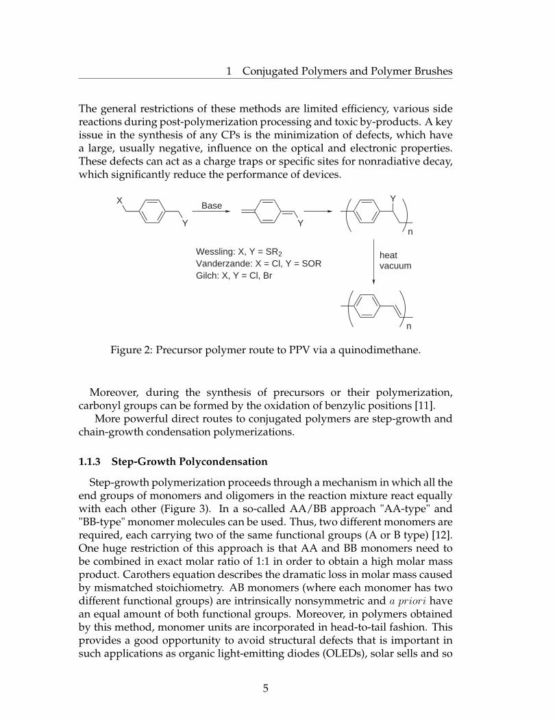
The idea was to prepare a soluble precursor, which upon eliminationof some molecular substituents via a thermal treatment, may produce theconjugated form of the polymer. Early attempts to synthesize poly(phenylvinylene) (PPV)-type polymers had started from variations of Ullmann [3] orWurtz-Fittig [4] reactions. Other methods used Kovaci′s [5, 6] and Wesslingmethods (Figure 2) [7, 8, 9]. Gilch [10] route utilizes halide leaving groups.
4
1 Conjugated Polymers and Polymer Brushes
The general restrictions of these methods are limited efficiency, various sidereactions during post-polymerization processing and toxic by-products. A keyissue in the synthesis of any CPs is the minimization of defects, which havea large, usually negative, influence on the optical and electronic properties.These defects can act as a charge traps or specific sites for nonradiative decay,which significantly reduce the performance of devices.
X
Y
Base
Y
Y
n
heatvacuum
n
Wessling: X, Y = SR2
Vanderzande: X = Cl, Y = SORGilch: X, Y = Cl, Br
Figure 2: Precursor polymer route to PPV via a quinodimethane.
Moreover, during the synthesis of precursors or their polymerization,carbonyl groups can be formed by the oxidation of benzylic positions [11].
More powerful direct routes to conjugated polymers are step-growth andchain-growth condensation polymerizations.
1.1.3 Step-Growth Polycondensation
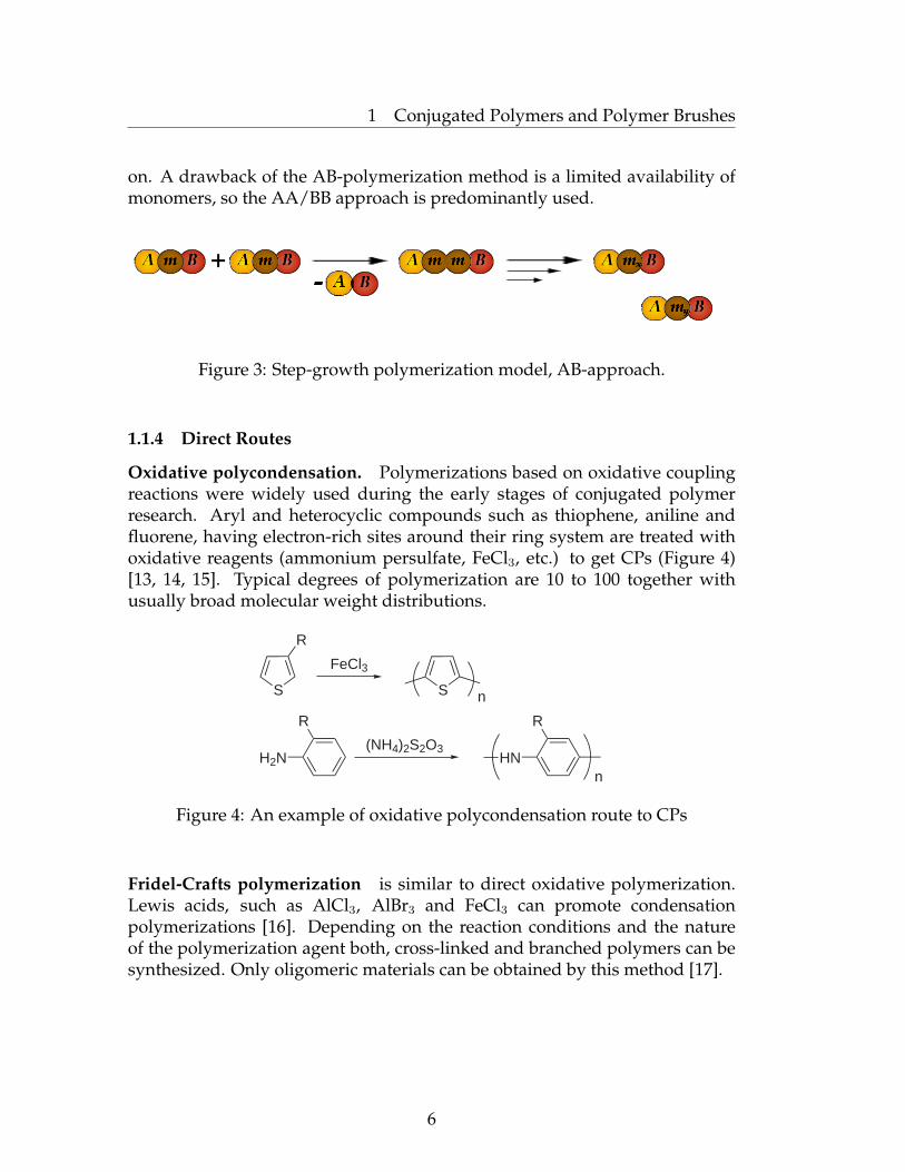
Step-growth polymerization proceeds through a mechanism in which all theend groups of monomers and oligomers in the reaction mixture react equallywith each other (Figure 3). In a so-called AA/BB approach "AA-type" and"BB-type" monomer molecules can be used. Thus, two different monomers arerequired, each carrying two of the same functional groups (A or B type) [12].One huge restriction of this approach is that AA and BB monomers need tobe combined in exact molar ratio of 1:1 in order to obtain a high molar massproduct. Carothers equation describes the dramatic loss in molar mass causedby mismatched stoichiometry. AB monomers (where each monomer has twodifferent functional groups) are intrinsically nonsymmetric and a priori havean equal amount of both functional groups. Moreover, in polymers obtainedby this method, monomer units are incorporated in head-to-tail fashion. Thisprovides a good opportunity to avoid structural defects that is important insuch applications as organic light-emitting diodes (OLEDs), solar sells and so
5
1 Conjugated Polymers and Polymer Brushes
on. A drawback of the AB-polymerization method is a limited availability ofmonomers, so the AA/BB approach is predominantly used.
Figure 3: Step-growth polymerization model, AB-approach.
1.1.4 Direct Routes
Oxidative polycondensation. Polymerizations based on oxidative couplingreactions were widely used during the early stages of conjugated polymerresearch. Aryl and heterocyclic compounds such as thiophene, aniline andfluorene, having electron-rich sites around their ring system are treated withoxidative reagents (ammonium persulfate, FeCl3, etc.) to get CPs (Figure 4)[13, 14, 15]. Typical degrees of polymerization are 10 to 100 together withusually broad molecular weight distributions.
S
R
H2N
R
FeCl3
S
HN
R
n
(NH4)2S2O3
n
Figure 4: An example of oxidative polycondensation route to CPs
Fridel-Crafts polymerization is similar to direct oxidative polymerization.Lewis acids, such as AlCl3, AlBr3 and FeCl3 can promote condensationpolymerizations [16]. Depending on the reaction conditions and the natureof the polymerization agent both, cross-linked and branched polymers can besynthesized. Only oligomeric materials can be obtained by this method [17].
6
1 Conjugated Polymers and Polymer Brushes
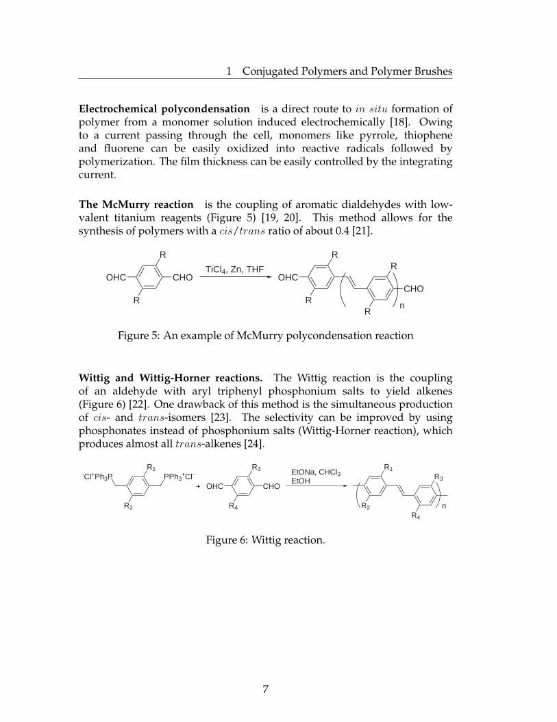
Electrochemical polycondensation is a direct route to in situ formation ofpolymer from a monomer solution induced electrochemically [18]. Owingto a current passing through the cell, monomers like pyrrole, thiopheneand fluorene can be easily oxidized into reactive radicals followed bypolymerization. The film thickness can be easily controlled by the integratingcurrent.
The McMurry reaction is the coupling of aromatic dialdehydes with low-valent titanium reagents (Figure 5) [19, 20]. This method allows for thesynthesis of polymers with a cis/trans ratio of about 0.4 [21].
OHC CHO
R
R
OHC
R
RCHO
R
R
TiCl4, Zn, THF
n
Figure 5: An example of McMurry polycondensation reaction
Wittig and Wittig-Horner reactions. The Wittig reaction is the couplingof an aldehyde with aryl triphenyl phosphonium salts to yield alkenes(Figure 6) [22]. One drawback of this method is the simultaneous productionof cis- and trans-isomers [23]. The selectivity can be improved by usingphosphonates instead of phosphonium salts (Wittig-Horner reaction), whichproduces almost all trans-alkenes [24].
-Cl+Ph3P PPh3+Cl-
R1
R2
OHC CHO
R3
R4
R1
R2R4
R3+
EtONa, CHCl3EtOH
n
Figure 6: Wittig reaction.
7
1 Conjugated Polymers and Polymer Brushes
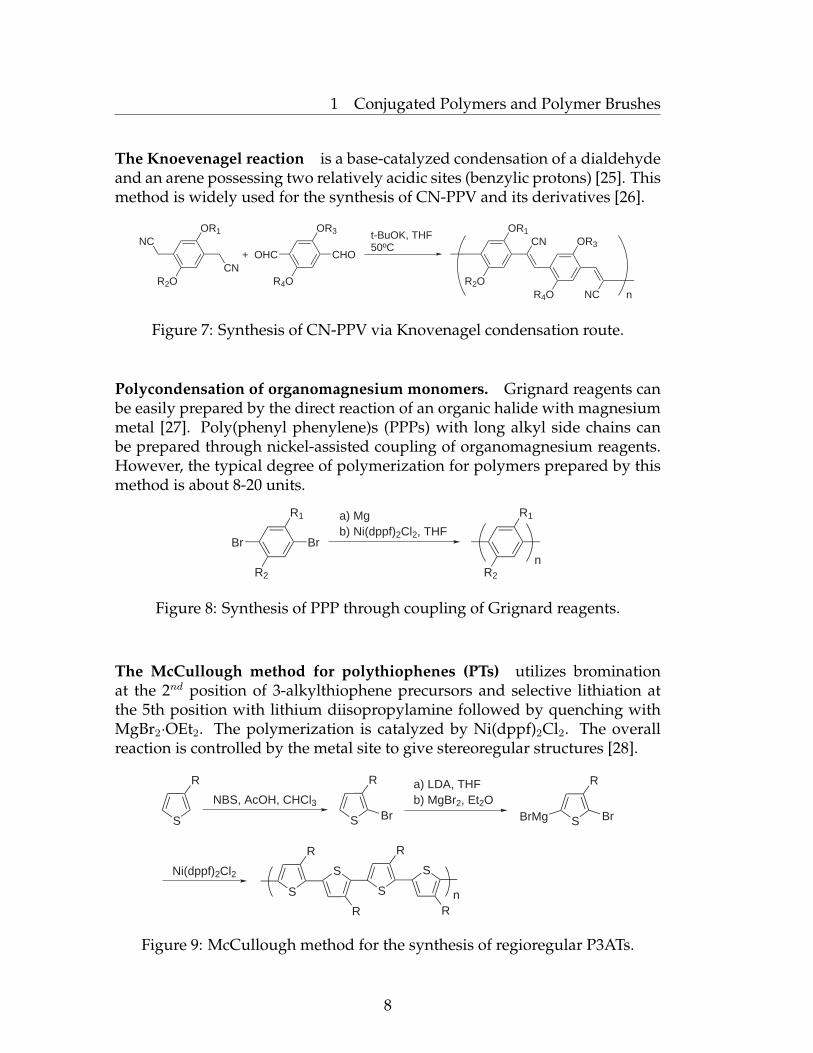
The Knoevenagel reaction is a base-catalyzed condensation of a dialdehydeand an arene possessing two relatively acidic sites (benzylic protons) [25]. Thismethod is widely used for the synthesis of CN-PPV and its derivatives [26].
NC
CN
OR1
R2O
OHC CHO
OR3
R4O
+
t-BuOK, THF50ºC
OR1
R2OR4O
OR3
n
CN
NC
Figure 7: Synthesis of CN-PPV via Knovenagel condensation route.
Polycondensation of organomagnesium monomers. Grignard reagents canbe easily prepared by the direct reaction of an organic halide with magnesiummetal [27]. Poly(phenyl phenylene)s (PPPs) with long alkyl side chains canbe prepared through nickel-assisted coupling of organomagnesium reagents.However, the typical degree of polymerization for polymers prepared by thismethod is about 8-20 units.
Br Br
R1
R2
a) Mgb) Ni(dppf)2Cl2, THF
R2
R1
n
Figure 8: Synthesis of PPP through coupling of Grignard reagents.
The McCullough method for polythiophenes (PTs) utilizes brominationat the 2nd position of 3-alkylthiophene precursors and selective lithiation atthe 5th position with lithium diisopropylamine followed by quenching withMgBr2·OEt2. The polymerization is catalyzed by Ni(dppf)2Cl2. The overallreaction is controlled by the metal site to give stereoregular structures [28].
S
R
S
R
S
R
S
R
Br
S
R
S
R
S
R
BrMg BrNBS, AcOH, CHCl3
a) LDA, THFb) MgBr2, Et2O
Ni(dppf)2Cl2
n
Figure 9: McCullough method for the synthesis of regioregular P3ATs.
8

1 Conjugated Polymers and Polymer Brushes
The Rieke method allows one to get CPs under mild conditions. Fororienting linkage selectivity, this method relies on organozinc reagents [29, 30]which react with aryl halides at -78oC to afford the corresponding Grignardreagents. The higher reactivity of zinc toward iodide, relative to bromide,leads to selective incorporation at the site opposite the alkyl substitution.
S
R
S
R
S
R
S
R
Br
S
R
S
R
S
R
IZn BrNBS, AcOH, CHCl3
a) I2, HNO3, CH2Cl2b) Reike Zn
Ni(dppe)2Cl2
n
Figure 10: Rieke method for the regioregular P3ATs.
The Heck reaction is a palladium-catalyzed formation of carbon-carbondouble bond between organic halides and olefins, in mostly trans configu-ration, with very few side reactions [31]. The reaction is compatible witha suitable range of chemical functionalities. The regioselectivity can becontrolled by the reaction conditions, by the substituents on the arylenecomponent, by living groups and by the choice of olefinic monomer [32].
Br Br
R1
R2
R1
R2
+Pd(PPh3)4, NEt3, THF
R1
R2n
Figure 11: Heck reaction for the synthesis of PPVs.
9

1 Conjugated Polymers and Polymer Brushes
The Suzuki reaction refers to the cross-coupling of aromatic organicelectrophiles such as aryl or vinylic halides (or triflates) with organoboronreagents (aryl boronic acids and their esters) in the presence of a base [33]. Themost commonly used palladium catalysts are Pd(PPh3)4, Pd(PPh3)2Cl2 andPd(OAc)2 with triphenylphosphine. Typical reaction is illustrated in Figure 12.The Suzuki reaction is tolerant to a broad range of functional groups and isunaffected by the presence of water. Boronic derivatives are easier to handlethan their corresponding acids and non-toxic by-products are formed. It hasbeen noted that 2,5-dialkylbenzene-1,4-bis(trimethyleneborate)s polymerizesmoothly to give higher molecular weight polymers than those obtained withthe parent boronic acids [34, 35].
Br Br
R1
R2
(HO)2B Br
R1
R2
(HO)2B B(OH)2
R1
R2
R1
R2
R1
R2
+Pd(PPh3)4, toluene
H2O, K2CO3 n
Pd(PPh3)4, toluene
H2O, K2CO3 n
Figure 12: Suzuki coupling reaction.
The Stille coupling reaction is the palladium-catalyzed coupling betweenan organostannane and halides or pseudohalides to form C-C bond with veryfew limitations on the R-groups [36]. The advantages are that organostannanesare not oxygen or moisture sensitive; however they are toxic and possess lowpolarity, which makes them poorly soluble in water.
SBu3Sn SnBu3
IC7H15
I C7H15
Pd(PPh3)2
C7H15
C7H15
S+
THF, H2O n
Figure 13: Synthesis of PATs via Stille coupling route.
10

1 Conjugated Polymers and Polymer Brushes
The Sonogashira-Hagihara reaction is the coupling of terminal alkyneswith aromatic bromides or iodides performed in the presence of palladiumcatalyst, a copper (I) co-catalyst and an amine base [37]. The correspondingiodides react considerably faster and lead to the higher yield at lower reactiontemperatures. Polymers obtained by this method have a molecular weightfrom thousands to hundreds of thousands.
I I
OR
RO
H H+Pd(PPh3)4, CuI
toluenediisopropylamine
OR
ROn
OR
RO
Figure 14: Sonogashira-Hagihara coupling.
Yamamoto-type cross-coupling refers to the C-C coupling via the con-densation of dihaloaromatic compounds [38]. By this approach, highmolecular weight polymers (up to Mn = 200 000 g/mol [39]) can be obtainedthrough the Ni(COD) (COD = cyclooctadiene) catalyst and dihalosubstitutedmonomers. A major advantage of this method is the straightforwardpreparation of the dihalohenated reactants. As compared to the FeCl3-catalyzed oxidative polymerization, Yamamoto coupling yields minimizedbranching. A disadvantage is the difficulty in removing catalyst residues fromthe product.
Br BrNi(COD)
n
Figure 15: An example of the Yamamoto polycondensation.
All the aforementioned synthetic routes are powerful methods to obtainCPs with the limited amount of defects. However, polymers synthesizedthrough these approaches possess broad molecular weight distributions. Thatis because these methods employ step-growth polymerization mechanisms,where all end groups of monomers and oligomers in the reaction mixture reactequally with each other. In addition, the preparation of complex architecturesof conjugated polymers such as brushes or block copolymers is hardly possiblewith these step-growth polycondensation methods.
11
1 Conjugated Polymers and Polymer Brushes
1.1.5 Chain-Growth Condensation Polymerization for Conjugated Poly-mers
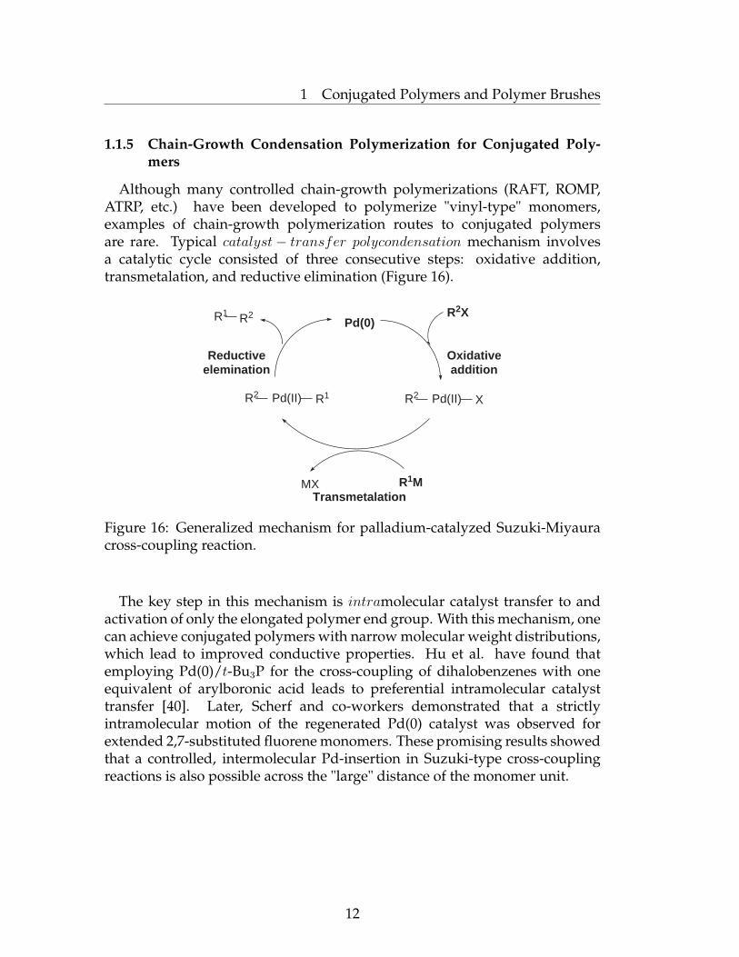
Although many controlled chain-growth polymerizations (RAFT, ROMP,ATRP, etc.) have been developed to polymerize "vinyl-type" monomers,examples of chain-growth polymerization routes to conjugated polymersare rare. Typical catalyst− transfer polycondensation mechanism involvesa catalytic cycle consisted of three consecutive steps: oxidative addition,transmetalation, and reductive elimination (Figure 16).
R1 R2
R2 Pd(II) R1 R2 Pd(II) X
MX
Pd(0)R2X
R1M
Oxidativeaddition
Reductiveelemination
Transmetalation
Figure 16: Generalized mechanism for palladium-catalyzed Suzuki-Miyauracross-coupling reaction.
The key step in this mechanism is intramolecular catalyst transfer to andactivation of only the elongated polymer end group. With this mechanism, onecan achieve conjugated polymers with narrow molecular weight distributions,which lead to improved conductive properties. Hu et al. have found thatemploying Pd(0)/t-Bu3P for the cross-coupling of dihalobenzenes with oneequivalent of arylboronic acid leads to preferential intramolecular catalysttransfer [40]. Later, Scherf and co-workers demonstrated that a strictlyintramolecular motion of the regenerated Pd(0) catalyst was observed forextended 2,7-substituted fluorene monomers. These promising results showedthat a controlled, intermolecular Pd-insertion in Suzuki-type cross-couplingreactions is also possible across the "large" distance of the monomer unit.
12

1 Conjugated Polymers and Polymer Brushes
Yokozawa et al. [41] found that the chain-growth mechanism is quitegeneral for metal-catalyzed polymerization of AB-type monomers. Theyfound, in particular, that polycondensation of monomers like 7-bromo-9,9-bis(2-ethylhexyl)-9H-fluoren-2-ylboric acid ester catalyzed by Pd complexeswith bulky and electron-reach phosphine ligands (Suzuki-Miyaura poly-condensation) can also be performed in a chain-growth manner. Theyused a stable aryl palladium(II) halide complex as an externally-addedinitiator. The aryl group of the initiator served as the end group of thegrowing polymer chain. The molecular weight of the obtained polymerincreased linearly in proportion to the conversion of monomers with lowpolydispersity. The degree of polymerization was strongly dependent onthe feed ratio of the monomer to the initiator. All these facts confirm thechain-growth polymerization mechanism for Suzuki-Miyaura cross-couplingpolymerization. This reaction will be considered in more detail in Chapter 3.
BrPd(PtBu3)2
Pd BrPtBu3
Br B
R R
O
O
R R
n
Figure 17: Synthesis of PF2/6 via Suzuki-Miyaura chain-growth polymeriza-tion.
13

1 Conjugated Polymers and Polymer Brushes
Recently, Yokozawa and McCullough developed a method to polymerizealkylthiophenes via the catalyst-transfer polycondensation route. The pro-posed catalyst-transfer condensation polymerization mechanism is depictedin Figure 18.
SMgCl Br
C6H13
SBr
C6H13
S
C6H13
S
C6H13
Br
SBr
C6H13
S
C6H13
NiL2
NiL2
Br
SBr NiL2
C6H13
SMgCl Br
C6H13
SBr
C6H13
S
C6H13
S
C6H13
NiL2
SBr
C6H13
SBr
C6H13
S
C6H13
NiL2
Br
SBr
C6H13
S
C6H13
Br
SMgCl Br
C6H13
NiL2
SBr
C6H13
SBr
C6H13
S
C6H13
S
C6H13
NiL2 Br 5M HClS
Br
C6H13
S
C6H13
H
Ni(dppp)Cl2
n n+1
L2 = dppp
Figure 18: Catalyst-transfer condensation polymerization mechanism.
Thus, Ni(dppp)Cl2 reacts with two equivalents of Grignard thiophenemonomer, and the coupling reaction occurs with concomitant generation ofa zero-valent Ni complex. The Ni(0) complex does not diffuse into the reactionmixture, but is instead inserted into the intramolecular C-Br bond. AnotherGrignard thiophene monomer reacts with this Ni, followed by the couplingreaction and transfer of the Ni catalyst to the next C-Br bond. Growthcontinues in such a way that the Ni catalyst moves to the polymer endgroup [42].
The effect of the catalyst structure was investigated by Lucht et al. [43]. Itwas shown that the Ni complexes stabilized by bidentante phosphine ligandspossess a higher efficiency than those supported by monodentante ligands. Onthe other hand, Ni complexes are more efficient than Pd complexes.
The influence of the phosphine ligand of the Ni catalyst on the catalyst-transfer condensation polymerization was also investigated by Yokozawa andco-workers [44, 43]. Ni(dppe)Cl2 and Ni(PPh3)4 gave a polymer with a slightly
14

1 Conjugated Polymers and Polymer Brushes
lower Mn and a slightly broader molecular weight distribution, whereasNi(PPh3)Cl2, Ni(dppb)Cl2 and Ni(dppf)Cl2 gave polymers with low Mns and abroad molecular weight distribution. Ni(dppp)Cl2 resulted in a Mn value closeto the theoretical value based on the feed ratio of monomers to the catalyst andthe narrowest Mw/Mn ratio.
Also, it was shown that the quenching method plays a crucial role onthe polydispersity of obtained polymers. Yokozawa et al. found thatthe polymerization of 2-bromo-3-hexyl-5-iodothiophene with Ni(dppp)Cl2followed by quenching with 5M hydrochloric acid instead of water resultsin regioregular hexylthiophene-poly(3-hexylthiophene) (HT-P3HTs) with verylow polydispersity, and that the Mn is also controlled by the feed ratioof 2-bromo-3-hexyl-5-iodothiophene to Ni(dppp)Cl2 under this quenchingmethod [45].
Geng and co-workers have recently reported on the polymerization ofGrignard-type fluorene monomer with Ni(dppp)Cl2 [46]. The monomer wasgenerated from the corresponding bromoiodofluorene with i-PrMgCl/LiCl(1:1). The polymerization proceeded very quickly at 0oC and was nearlycompleted in 10 min. High molecular weight polyfluorene (Mn = 18 800 –86 000) was obtained at the very beginning, and the Mn almost remainedidentical at different conversions of the monomer. The Mw/Mn of the resultingpolymers was in the range 1.49-1.77.
ClMg Br
R R R R
Ni(dppp)Cl2
n
Figure 19: Synthesis of poly(octyl fluorene) (PFO) by the GRIM method.
In order to control the physical properties of thin-film devices basedon π-conjugated polymers, it is necessary to enable the organisation ofthe polymer molecules and their interactions with other constituents inmulticomponent devices. Moreover, guidable self-assembly properties mayresult in improved device performance. Thus, covering functionalizedsubstrates (planar surfaces, functionalized particles and so on) with covalentlygrafted conjugated polymers could be a powerful tool to obtain desirablefunctionalized surfaces.
15

1 Conjugated Polymers and Polymer Brushes
1.2 Polymer Brushes: Definition and Classification
1.2.1 Types of Polymer Brushes
The term "polymer brush" refers to an assembly of polymer molecules whichare attached at one or several anchor points to a surface or an interface atsufficient grafting density [47, 48, 49]. Tethering can be sufficiently densethat the polymer molecules are crowded and forced to stretch away from thesurface or interface due to excluded volume effect [50, 51]. This situation, inwhich polymer chains are stretched along the direction normal to the graftingsurface, is found to be present under equilibrium conditions. It is quitedifferent from the behaviour of flexible polymer chains in solution wherechains are present in a random-walk configuration [52].
Thanks to polymer brushes, it is possible to achieve different specialpolymer systems such as polymer micelles, block copolymers at fluid-fluidinterfaces, grafted polymers on a solid surface, adsorbed diblock copolymersand graft copolymers at fluid-fluid interfaces (Figure 20).
Adsorbed diblock
copolymers
Polymer micelle Diblock copolymer
melt
Graft polymers at
fluid-fluid interfaces
Block copolymers at
fluid-fluid interfaces
End-grafted
polymers
Figure 20: Examples of polymer systems comprising polymer brushes.
The conformation of grafted polymer chains mostly depends on the graftingdensity and interactions with the surface. At low grafting density, tetheredchains do not overlap, due to the distance between grafting sites, which islarger than the size of the chains. If interactions between molecular chains
16
1 Conjugated Polymers and Polymer Brushes
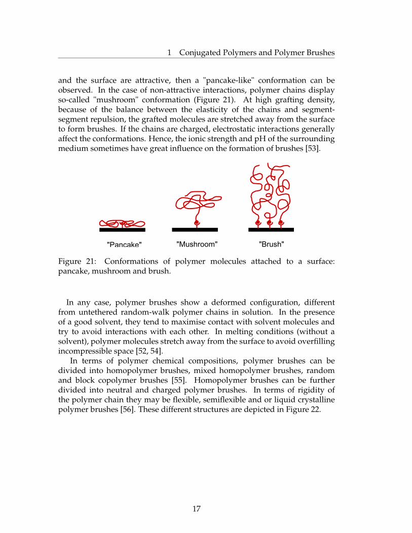
and the surface are attractive, then a "pancake-like" conformation can beobserved. In the case of non-attractive interactions, polymer chains displayso-called "mushroom" conformation (Figure 21). At high grafting density,because of the balance between the elasticity of the chains and segment-segment repulsion, the grafted molecules are stretched away from the surfaceto form brushes. If the chains are charged, electrostatic interactions generallyaffect the conformations. Hence, the ionic strength and pH of the surroundingmedium sometimes have great influence on the formation of brushes [53].
"Pancake" "Mushroom" "Brush"
Figure 21: Conformations of polymer molecules attached to a surface:pancake, mushroom and brush.
In any case, polymer brushes show a deformed configuration, differentfrom untethered random-walk polymer chains in solution. In the presenceof a good solvent, they tend to maximise contact with solvent molecules andtry to avoid interactions with each other. In melting conditions (without asolvent), polymer molecules stretch away from the surface to avoid overfillingincompressible space [52, 54].
In terms of polymer chemical compositions, polymer brushes can bedivided into homopolymer brushes, mixed homopolymer brushes, randomand block copolymer brushes [55]. Homopolymer brushes can be furtherdivided into neutral and charged polymer brushes. In terms of rigidity ofthe polymer chain they may be flexible, semiflexible and or liquid crystallinepolymer brushes [56]. These different structures are depicted in Figure 22.
17

1 Conjugated Polymers and Polymer Brushes
Flexible homopolymer brush Mixed homopolymer brush
Random copolymer brush Block copolymer brush
Charged homopolymer brush Liquid crystalline polymer brush
Semiflexible polymer brush
Figure 22: Classification of linear polymer brushes.
The conformation of surface-immobilized polymers can be evaluated viabrush heigh h as a function of graft density σ (A (cm2 per molecule) or C (molper cm2)), average distance of the anchor points dg and the molecular weightof the surface-tethered chains. In polymer brushes, the interval between thegrafting points of tethered chains is much smaller than the radius of gyrationrg of the same unperterbed chain which is not in contact with the surface.
To describe the equilibrium thickness of the grafted layer, Alexander
18
1 Conjugated Polymers and Polymer Brushes
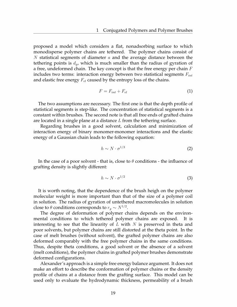
proposed a model which considers a flat, nonadsorbing surface to whichmonodisperse polymer chains are tethered. The polymer chains consist ofN statistical segments of diameter a and the average distance between thetethering points is dg, which is much smaller than the radius of gyration ofa free, undeformed chain. The key concept is that the free energy per chain Fincludes two terms: interaction energy between two statistical segments Fintand elastic free energy Fel caused by the entropy loss of the chains.
F = Fint + Fel (1)
The two assumptions are necessary. The first one is that the depth profile ofstatistical segments is step-like. The concentration of statistical segments is aconstant within brushes. The second note is that all free ends of grafted chainsare located in a single plane at a distance L from the tethering surface.
Regarding brushes in a good solvent, calculation and minimization ofinteraction energy of binary monomer-monomer interactions and the elasticenergy of a Gaussian chain leads to the following equation:
h ∼ N · σ1/3 (2)
In the case of a poor solvent - that is, close to θ conditions - the influence ofgrafting density is slightly different:
h ∼ N · σ1/2 (3)
It is worth noting, that the dependence of the brush heigh on the polymermolecular weight is more important than that of the size of a polymer coilin solution. The radius of gyration of untethered macromolecules in solutionclose to θ conditions corresponds to rg ∼ N1/2.
The degree of deformation of polymer chains depends on the environ-mental conditions to which tethered polymer chains are exposed. It isinteresting to see that the linearity of L with N is preserved in theta andpoor solvents, but polymer chains are still distorted at the theta point. In thecase of melt brushes (without solvent), the grafted polymer chains are alsodeformed comparably with the free polymer chains in the same conditions.Thus, despite theta conditions, a good solvent or the absence of a solvent(melt conditions), the polymer chains in grafted polymer brushes demonstratedeformed configurations.
Alexander’s approach is a simple free energy balance argument. It does notmake an effort to describe the conformation of polymer chains or the densityprofile of chains at a distance from the grafting surface. This model can beused only to evaluate the hydrodynamic thickness, permeability of a brush
19
1 Conjugated Polymers and Polymer Brushes
and the force per area required to compress a brush. Nevertheless, it allowsus to predict and understand such essential properties of polymer brushes aslubrication and wetting behaviour. More advanced models are required tocharacterise the segment density profile correctly or to describe the variety ofcharged polymer molecules [57].
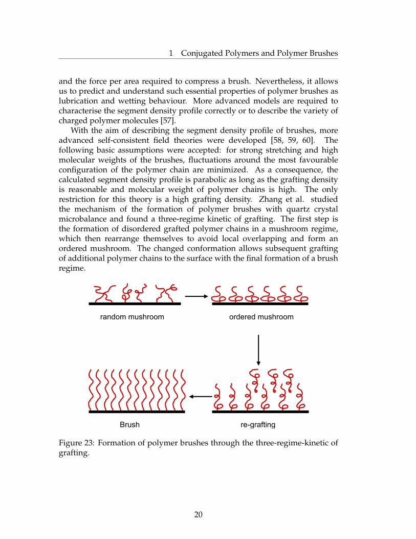
With the aim of describing the segment density profile of brushes, moreadvanced self-consistent field theories were developed [58, 59, 60]. Thefollowing basic assumptions were accepted: for strong stretching and highmolecular weights of the brushes, fluctuations around the most favourableconfiguration of the polymer chain are minimized. As a consequence, thecalculated segment density profile is parabolic as long as the grafting densityis reasonable and molecular weight of polymer chains is high. The onlyrestriction for this theory is a high grafting density. Zhang et al. studiedthe mechanism of the formation of polymer brushes with quartz crystalmicrobalance and found a three-regime kinetic of grafting. The first step isthe formation of disordered grafted polymer chains in a mushroom regime,which then rearrange themselves to avoid local overlapping and form anordered mushroom. The changed conformation allows subsequent graftingof additional polymer chains to the surface with the final formation of a brushregime.
random mushroom ordered mushroom
re-graftingBrush
Figure 23: Formation of polymer brushes through the three-regime-kinetic ofgrafting.
20

1 Conjugated Polymers and Polymer Brushes
1.2.2 Synthesis of Polymer Brushes
Generally, there are two principal requirements to force tethered polymersinto a brush-like conformation. The first one is that the polymer chainsare firmly and irreversibly fixed to the surface of the substrate. Anotherrequirement is that the synthetic route allows for obtaining a system withrather high grafting density to cause the repulsion between polymer segmentsand, as a result, significant chain stretching. Thus, synthetic strategies canbe classified into three approaches with respect to the driving force for brushformation: phase-separation, physiosorption and chemisorption.
The Phase− separation approach consists of spreading of an amphiphilicblock copolymer at an air-water interface. Hence, water-soluble blocks tendto dissolve in the aqueous phase whereas the anchored water-insoluble partattempts to prevent it. During the compression of this Langmuir layer, thedistance between the anchor points decreases and the hydrophilic parts arestretched away from the surface into the water phase. It is worth noting, thatthe hydrophilic balance has to be taken into account to avoid the formationof micelles. The obtained films can be crosslinked photochemically andtransferred to a solid substrate.
Tethering of polymer chains onto a solid surface can be a reversibleor irreversible process. Physisorption is a reversible process, when blockcopolymers or end-functionalized polymers are physisorbed to a solid surface(Figure 24) [48]. In the case of selective solvents [61], an ideal solvent leadsto precipitation of one block (or end-group) which forms an "anchor" layer onthe surface, whereas interactions between another part of the polymer and thesolvent are much stronger. Hence, polymer brushes are formed in solution.The same concept is applicable for selective surfaces [62, 63]: one block ispreferentially adsorbed on the surface and another one forms a polymer brush.Preparation of polymer brushes by this method is not difficult. However, dueto the weak interactions (van der Waals forces or hydrogen bonding) betweenthe substrate and the block copolymers, polymer brushes are highly unstabletowards thermal and solvent treatments [64]. Some of these drawbacks couldbe overcome by covalently tethering polymer chains to substrates.
An alternative and more powerful approach is chemisorption of polymermolecules. This irreversible process leads to chains which are covalentlybound to the surface [65, 66, 67, 68]. The method can be divided into "graftingfrom" and "grafting to" approaches.
21

1 Conjugated Polymers and Polymer Brushes
B
A A A A I I I I
*
M
MM
M
M
Physisorption
"Grafting to" "Grafting from"
Figure 24: Preparation of polymer brushes by "physisorbtion", "grafting to"and "grafting from" approaches.
Via the "grafting to" route, one can prepare tethered polymer brushesby reacting end-functionalized polymers with a suitable surface underappropriate conditions. This is a simple and direct route, which hovewer hasseveral limitations. The benefit is that end-functionalized polymer moleculescan be synthesised by living anionic, cationic or radical polymerizations and,thus, possess narrow polydispersity and controllable molecular weight. Onthe other hand, only a small amount of polymer can be immobilized ontothe surface by this method. During this process, macromolecular chains mustdiffuse through the existing polymer film to reach the reactive sites on thesurface. Overcoming this barrier becomes more and more difficult at highergrafting densities. Therefore, the thickness of films is usually in the range of3-5 nm and the grafting density is also rather low. To avoid these drawbacks,the "grafting from" approach was developed.
The "grafting from" method is a powerful tool to prepare tethered polymerson a solid substrate surface. Obtained brushes usually possess high grafting
22
1 Conjugated Polymers and Polymer Brushes
density and a thickness up to 2000 nm in the dry state. At the first stage,the initiator must be immobilized onto the surface and after that via surfaceinitiated polymerization tethered polymers are generated. Chain-growthliving polymerizations, such as controlled radical polymerization (NMP,ATRP, etc.), anionic polymerization or ROMP were used. They allow forthe preparation of surface-attached polymer chains with desirable molecularweight and narrow polydispersity. Thus, the "grafting-from" method isobviously a very powerful way to prepare polymer brushes with differentfunctionalities.
1.2.3 Chain-Growth vs. Step-Growth Polymerization Routes to Conju-gated Polymer Brushes
In spite of its obvious promise, little research has been performed in the fieldof CP brushes [69, 70] because of great difficulties in their preparation [71, 72].
The "grafting-to" approach, based on the coupling of end-functionalpolymers with a complimentarily terminated surface, usually provides ratherlow grafting densities [73]. This method has been widely employed inthe modification of particles by nonconjugated polymers and has also beenexemplified in the grafting of conjugated polymers, for example, by the at-tachment of thiol end-functionalized polyacetylene to gold nanoparticles [74]or amino-functionalized P3HT to quantum dots [75]. Typically, the synthesis ofconjugated polymers involves polycondensation reactions employing a step-growth polymerization mechanism [76, 77]. In this case, polymer chainspropagate randomly by the coupling of monomers and/or earlier formedoligomeric fragments via the abstraction of small molecules. Thus, evenif an appropriate anchoring group (able to couple with the monomer) wasimmobilized on the surface, the process in the best case leads to a mixtureof grafted chains and a large amount of unattached polymer. In practice,this approach fails to produce CP brushes with reasonable grafting densities,since polymerization products form faster in solutions, precipitate onto thesurface, and hinder growth from the surface. There are few examples inthe literature describing the "reactive-grafting onto" or "grafting-through"approach whereby growing CP polymer chains are grafted onto properlyfunctionalized reactive surfaces [78]. Following this strategy, Schanze et al.performed grafting of polyacetylene that resulted in polymer brushes thatwere limited to athickness of 12 nm [79].
Surface-initiated polymerization, or the "grafting-from" approach [80], amethod of growing polymer chains selectively from functionalized particlesvia one-by-one addition of monomers to surface-immobilized initiators, isone of the most powerful synthetic approaches for the creation of polymerbrushes of variable composition and a tunable grafting density. However, thisapproach is problematic for the grafting of conjugated polymers because of the
23
1 Conjugated Polymers and Polymer Brushes
step-growth character of most of synthetic routes to CPs [81].In general, for the realisation of surface-initiated polymerization, suitable
initiators should be attached to the surface, and the polymerization reactionhas to involve the chain-growth mechanism. Since the synthetic proceduredeveloped by Yokozawa et al. [41] fulfils the crucial last requirement, weexplore the possibility of employing Suzuki catalyst transfer polycondensationin the preparation of polyfluorene brushes.
24

2 Experimental Techniques
2 Experimental Techniques
2.1 Ultraviolet-Visible Spectroscopy: Basic Principle, Beer-Lambert Law, Spectrometr Construction
Ultraviolet-visible spectroscopy involves the spectroscopy of photons in UV-visible region, where the molecules undergo electronic transitions. Visiblewavelengths cover a range from approximately 400 to 800 nm. Thelongest visible wavelength is red and the shortest is violet, corresponding to36-72 kcal/mole respectively. This is enough to excite a molecular electron toa higher energy orbital.
Figure 25: Schematic diagram of possible molecular electronic levels.
At room temperature, the majority of molecules are in the "ground state", thelowest vibrational state of the lowest electronic energy level. Absorption of UVor visible light leads to the excitement of an electron from E1 to E2 level. TheUV-vis absorption bands are characteristically broad because the promotion ofelectron can occur from the E1 to any of the vibrational or rotational levels ofE2. Thus, according to the aforementioned and also selection rule, the mostprobable transitions are n→ π∗ and π → π∗.
25

2 Experimental Techniques
Figure 26: Schematic diagram showing possible molecular electronictransitions, and vibrational and rotational levels.
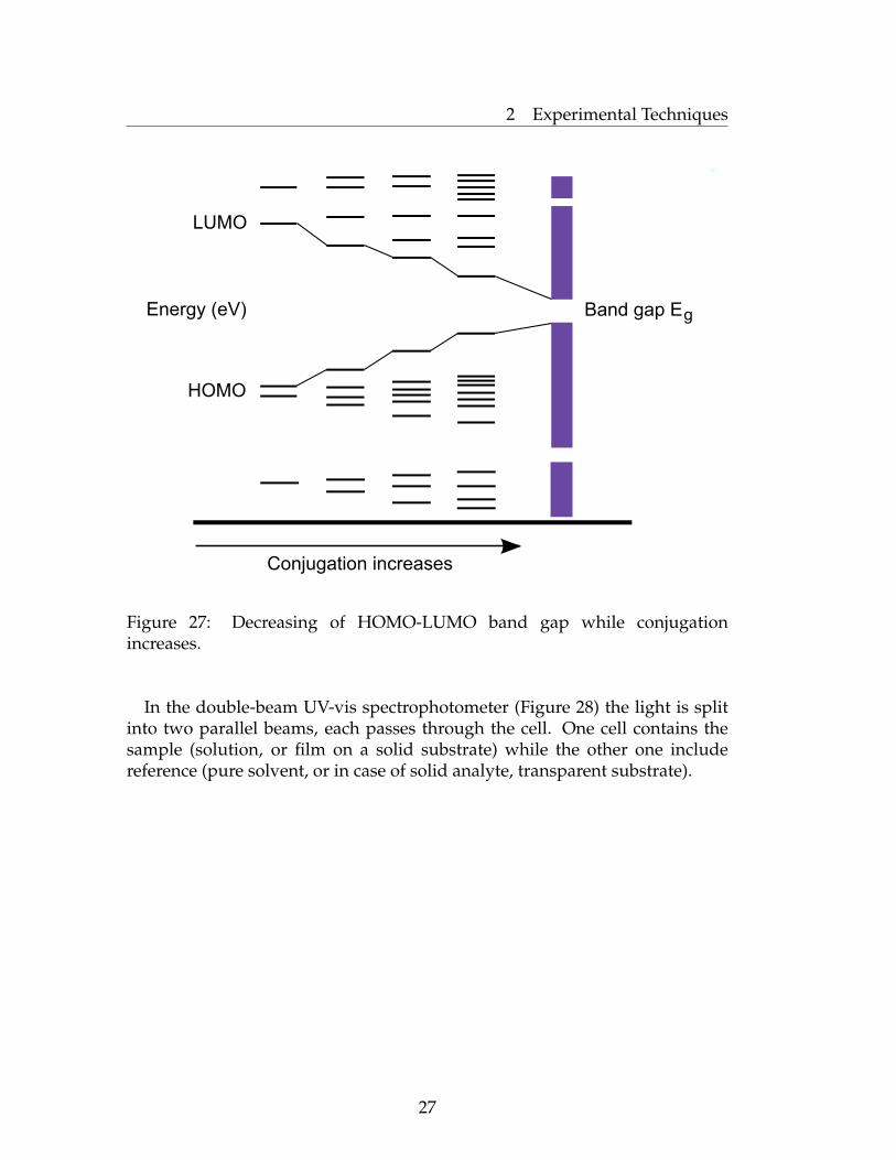
Conjugated polymers usually demonstrate bathochromic shifts in theabsorption maxima. That is because the increased conjugation brings theHOMO and LUMO orbitals closer together. The energy required to effectthe electron promotion is therefore less, and the wavelength is increasedcorrespondently. The same situation is observed for planar conjugatedpolymer systems. Improved planarity leads to the bathochromic shifts in theabsorption maxima.
26
2 Experimental Techniques
Figure 2.3. Decreasing of HOMO-LUMO band gap while conjugation increases.
LUMO
HOMO
Energy (eV) Band gap Eg
Conjugation increases
Figure 27: Decreasing of HOMO-LUMO band gap while conjugationincreases.
In the double-beam UV-vis spectrophotometer (Figure 28) the light is splitinto two parallel beams, each passes through the cell. One cell contains thesample (solution, or film on a solid substrate) while the other one includereference (pure solvent, or in case of solid analyte, transparent substrate).
27

2 Experimental Techniques
reference
cell
sample
cell
mirror
rotating
disc
mirror
slitlight source
difraction
grating
detector
and
computer
chart recorder
Figure 28: Schematic representation of a double beam spectrometr.
The detector measures the intensity of the light transmitted through thereference, I0, and through the sample. The absorbance is calculated from therelationship:
A = lgI
I0
(4)
According to the Beer-Lambert law, the absorbance A of the solution isproportional to the path length (l, length of cell, in cm) and the concentrationof adsorbing molecule (c, moles per litre), according to the equation
A = εcl (5)
where ε the molar extinction coefficient. The absorbance of a solution willvary as the concentration or the size of container varies. Molar absorptivity isindependent from it being divided by the concentration and the length of thesolution that the light passes through.
Thus, this is an efficient technique for determination of concentration aswell as various parameters of conjugated systems, such as planarity, degree ofpolymerization.
In this work UV-vis measurements were carried out using a Perkin ElmerUV/vis Spectrometr Lambda 800.
28
2 Experimental Techniques
2.2 Fluorescence Spectroscopy
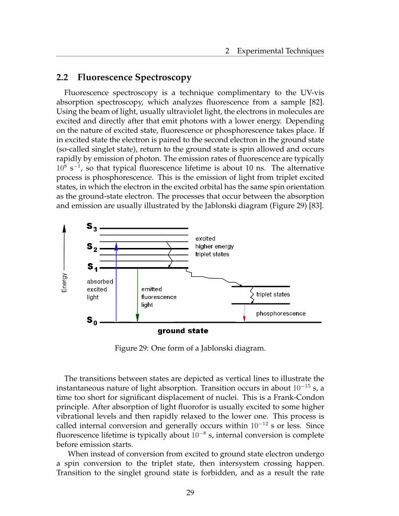
Fluorescence spectroscopy is a technique complimentary to the UV-visabsorption spectroscopy, which analyzes fluorescence from a sample [82].Using the beam of light, usually ultraviolet light, the electrons in molecules areexcited and directly after that emit photons with a lower energy. Dependingon the nature of excited state, fluorescence or phosphorescence takes place. Ifin excited state the electron is paired to the second electron in the ground state(so-called singlet state), return to the ground state is spin allowed and occursrapidly by emission of photon. The emission rates of fluorescence are typically108 s−1, so that typical fluorescence lifetime is about 10 ns. The alternativeprocess is phosphorescence. This is the emission of light from triplet excitedstates, in which the electron in the excited orbital has the same spin orientationas the ground-state electron. The processes that occur between the absorptionand emission are usually illustrated by the Jablonski diagram (Figure 29) [83].
excited
higher energy
triplet states
triplet states
phosphorescence
emitted
fluorescence
light
absorbed
excited
light
ground state
Ene
rgy
S3
S2
S1
S0
Figure 29: One form of a Jablonski diagram.
The transitions between states are depicted as vertical lines to illustrate theinstantaneous nature of light absorption. Transition occurs in about 10−15 s, atime too short for significant displacement of nuclei. This is a Frank-Condonprinciple. After absorption of light fluorofor is usually excited to some highervibrational levels and then rapidly relaxed to the lower one. This process iscalled internal conversion and generally occurs within 10−12 s or less. Sincefluorescence lifetime is typically about 10−8 s, internal conversion is completebefore emission starts.
When instead of conversion from excited to ground state electron undergoa spin conversion to the triplet state, then intersystem crossing happen.Transition to the singlet ground state is forbidden, and as a result the rate
29
2 Experimental Techniques
constants for triplet emission are several orders of magnitude smaller thanthose for fluorescence.
The phenomenon of fluorescence displays a number of general character-istics. The energy of emission is typically less than that of absorption. Afterexcitation system can relax not only emitting a photon, but also loose someenergy via non-radiative decay (heating, quenching and so on). The energydifference between absorbed and emitted photons is the Stokes shift [84].
The fluorescence lifetime and quantum yield are also perhaps the mostimportant characteristics of a fluorophore. The quantum yield is a ratio ofnumbers of emitted photons to the absorbed photons and can be schematicallypresented by a simplified Jablonski diagram (Figure 29). The fraction offluorofores that decay through emission, and hence quantum yield Q, is givenby (6), where the emissive rate of the fluorofore is depicted by Γ and κnr refersto the non-radiative decay (quenching). Quenching can be induced by electrontransfer from one molecule to the other, intersystem crossing to the tripletstate and variety of other trivial mechanisms. Thus, it is clear, that the largestquantum yield leads to the brightest emission, but it’s meaning is always lessthan unity because of Stokes losses.
Q =Γ
Γ + κnr(6)
The fluorescence lifetime is defined by the average time the molecule staysin the excited state before emitting a photon. Generally it proceeds around10 ns. In case of fluorofore illustrated in Figure 29 the lifetime is
τ =1
Γ + κnr(7)
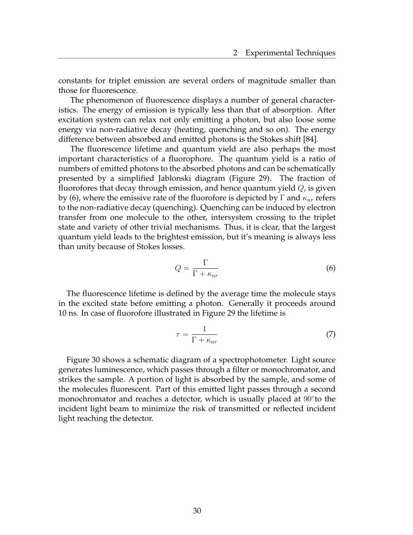
Figure 30 shows a schematic diagram of a spectrophotometer. Light sourcegenerates luminescence, which passes through a filter or monochromator, andstrikes the sample. A portion of light is absorbed by the sample, and some ofthe molecules fluorescent. Part of this emitted light passes through a secondmonochromator and reaches a detector, which is usually placed at 90◦to theincident light beam to minimize the risk of transmitted or reflected incidentlight reaching the detector.
30
2 Experimental Techniques
Xe lampExcitation
monochromator
Sample cell
Emission
monochromator
Photodetector
Figure 30: Schematic representation of spectrophotometer.
2.3 Ellipsometry
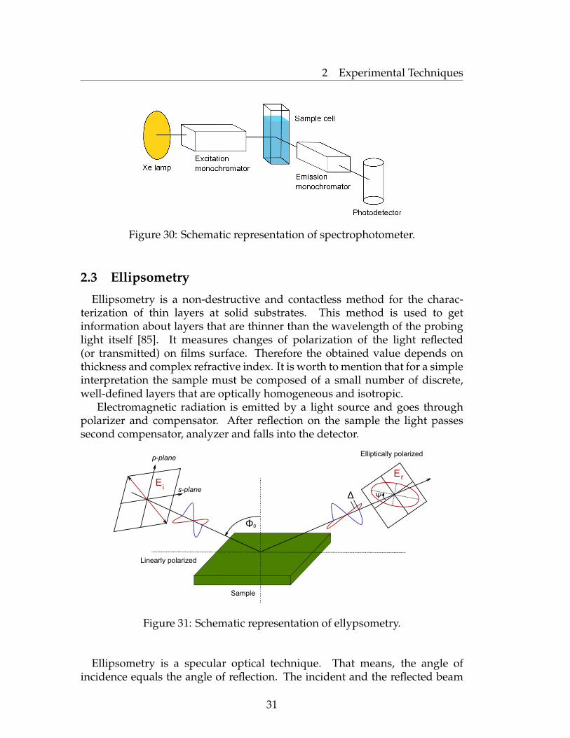
Ellipsometry is a non-destructive and contactless method for the charac-terization of thin layers at solid substrates. This method is used to getinformation about layers that are thinner than the wavelength of the probinglight itself [85]. It measures changes of polarization of the light reflected(or transmitted) on films surface. Therefore the obtained value depends onthickness and complex refractive index. It is worth to mention that for a simpleinterpretation the sample must be composed of a small number of discrete,well-defined layers that are optically homogeneous and isotropic.
Electromagnetic radiation is emitted by a light source and goes throughpolarizer and compensator. After reflection on the sample the light passessecond compensator, analyzer and falls into the detector.
Ei
Elliptically polarized
E r
p-plane
s-plane
Linearly polarized
Sample
Φ0
Δ Ψ
Figure 31: Schematic representation of ellypsometry.
Ellipsometry is a specular optical technique. That means, the angle ofincidence equals the angle of reflection. The incident and the reflected beam
31

2 Experimental Techniques
span the plane of incidence. Light, which is polarized parallel to this plane,is named "p-polarised". A perpendicular polarization direction (and parallelto the sample surface) is called "s-polarised". The amplitudes of s and pcomponents after reflection and normalization are expressed by Rs and Rp,respectively. Ellipsometry measures the ratio of Rs and Rp.
ρ =Rp
Rs
= tan(ψ)ei∆ (8)
where tan(ψ) is the amplitude ratio upon reflection and ∆ is the phaseshift [85]. Because ellipsometry measures the ratio of two values, it is veryaccurate and highly reproducible.
Ellipsometry is an indirect method. In general the measured ψ and ∆cannot be converted directly into the optical constants of the sample. A modelanalysis must be performed. Direct inversion of ψ and ∆ is only possible invery simple cases of isotropic, homogeneous and infinitely thick films. In allother cases a layer model must be established, which considers the opticalconstants and thickness of all individual layers of the sample. Using aniterative procedure unknown optical constants and/or thickness parametersare varied, and ψ and ∆ values are calculated. The calculated ψ and ∆ values,which match the experimental data best, provide the optical constants andthickness parameters of the sample.
Optical constants. The interaction of light with the substrate can bedescribed through the optical constants. The complex refractive index can berepresented by:
n = n+ ik (9)
where n is the real part of refraction and describes the phase velocity of lightin material. The following equation describes the relationships between n, c(speed of light in vacuum) and υ (speed of light in the material).
n =c
υ(10)
The imaginary part κ (or extinction coefficient) describes how fast theamplitude of the wave decreases. The extinction coefficient is related to theabsorption coefficient α by:
α =4πκ
λ(11)
where λ is the wavelength of light [86].
32

2 Experimental Techniques
The thickness of polymer layers was measured at λ = 633 nm and 90◦ ofincidence light with SENTECH SE-402 microfocus null-ellipsometr (lateralresolution is defined by the beam spot of about 20 µm in diameter). Amultilayer model for films covering or grafted on the silicon substrate has beenused for the calculation the thickness of the polymer layers. The refractiveindices used in the calculations were n=1.459 for native silicon oxide layerSiO2, n=1.525 for PGMA, n=1.63 for PS(Br), n=1.683 for PVK(Br), n=1.42 forsilane and n=1.7 for PF2/6 [87].
2.4 Atomic Force Microscopy
Atomic Force Microscopy (AFM) belongs to a broad family of methodsnamed Scanning Probe Microscopy (SPM) for imaging and characterization ofsurfaces on a microscopic scale. The development of the AFM was preceded bythe development of the Scanning Tunneling Microscope (STM) in 1982 at IBMZurich Research Laboratory by G. Binnig and H. Rohrer [88]. Later Binnigand co-workers [89] invented AFM, enabling one to image surfaces on thenanometer scale [90, 91]. During the scanning process cantilever with a sharptip interacts with the specimen to form three-dimensional surface topographyimage of nanometer lateral and subangstrom vertical resolution. A principalschematic of AFM is shown in Figure 32.
Normal force
friction
Sample
z
y
x
Figure 32: Schematic representation of AFM working principle.
The forces between them (van der Waals, electrostatic, magnetic) are notmeasured directly, but calculated by measuring the deflection of cantilever.Hook’s law gives F = −kz, where F is the force, k is the spring constant(stiffness of the lever) and z is the displacement from the equilibriumconditions. Knowing k and z, it is easily to calculate the force. The relationbetween force and distance is shown in Figure 33.
33

2 Experimental Techniques
Figure 33: Plot of van der Waals force vs. distance.
In the contact region, the distance between canteliver and sample is lessthan a few angstroms, and the force is repulsive. In the non-contact region theforce between the canteliver and the sample is attractive and the distance is inorder of tens to hundreds angstroms. The choice of operating scanning modedepends on the region of this curve. Non-contact mode is used to be used inthe attractive region, whereas contact mode in the repulsive. Tapping modefluctuates between two of them.
The smoothness of the polymer layer can be measured using root meansquare (RMS) roughness parameter. RMS value can be calculated from thefollowing equation:
RMS =
√∑Ni=1(Zi − Zave)2
N(12)
where Zave =∑N
i=1 Zi
N, Zi is height at certain point of measured area, Zave is
average Z value within the area, N is number of measured points within area.The rougher surface gives the larger value of RMS parameter.
In this work the Multimode AFM (Digital Instruments, Santa Barbara)was operated with amplitude feedback and in a "light" tapping modeconfiguration. The amplitude setpoint was set to the maximum possible value.Silicon tips with a spring constant of 0.3 N m−1 and a resonance frequency of250-300 KHz were used.
34

2 Experimental Techniques
2.5 Other Experimental Techniques1H and 31P spectroscopies. 1H and 31P NMR spectra were recorded on a
Bruker DRX-500 spectrometr operating at 500.13 MHz for 1H using CDCl3and THF-d8 as a solvents. The spectra were referenced on the solvent peakδ(1H)=7.26 ppm.
Gel Permission Chromatography (GPC). GPC measurments were carriedout on a Knauer, Hewlett-Packard normal-temperature size exclusionchromatograph, equipped with refractive index detector and two column PLMIXED-C (Polymer Laboratories Ltd, UK), eluent - chloroform. Calibrationwas baced on polystyrene standarts obtained from Polymer Standarts Service.
X-Ray Photoelectron Spectroscopy (XPS). XPS studies were performedusing of an AXIS ULTRA photoelectron spectrometer (Kratos Analytical,Manchester, England). The spectrometr was equipped with a monochromaticAl Kα (hν = 1486.6 eV) X-ray source of 300 W at 15 kV. The kinetic energy ofthe photoelectrons was determined with a determined with a hemisphericalanalyzer set to a pass energy of 160 eV for wide-scan spectra and 20 eV forhigh resolution spectra. During all measurements electrostatic charging of thesample was compensated by low-energy electron source.
35
3 Grafting of PF2/6 by Chain-Growth Suzuki Polycondensation
3 Grafting of PF2/6 by Chain-Growth SuzukiPolycondensation
3.1 Introduction
Currently, palladium-catalyzed Suzuki coupling polycondensation of arylhalides with organoboron reagents is a remarkably efficient route to conju-gated polymers [92]. In its classical performance, Suzuki polycondensationis catalyzed by Pd(PPh3)4 or similar complexes and involves a step-growthmechanism. As in the parent Suzuki cross-coupling, the mechanism of Suzukipolycondensation involves three basic consecutive steps: transmetallation,reductive elimination and oxidative addition (Figure 16).
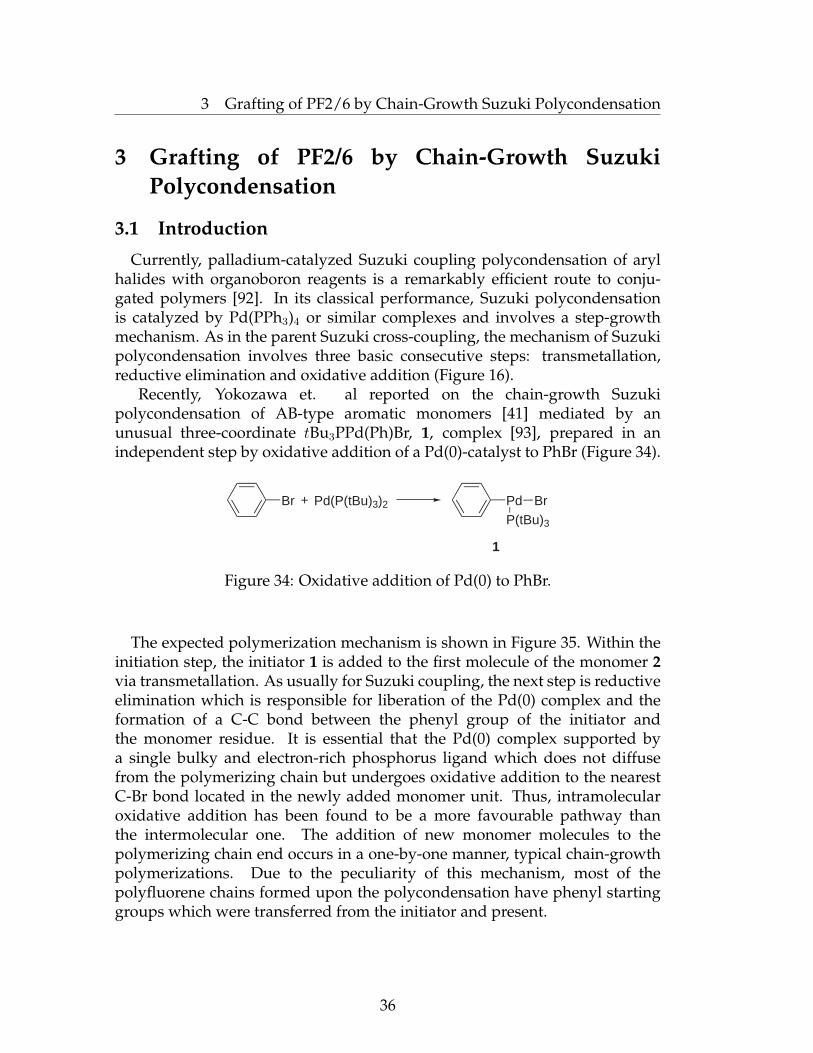
Recently, Yokozawa et. al reported on the chain-growth Suzukipolycondensation of AB-type aromatic monomers [41] mediated by anunusual three-coordinate tBu3PPd(Ph)Br, 1, complex [93], prepared in anindependent step by oxidative addition of a Pd(0)-catalyst to PhBr (Figure 34).
Br Pd(P(tBu)3)2+ Pd BrP(tBu)3
1
Figure 34: Oxidative addition of Pd(0) to PhBr.
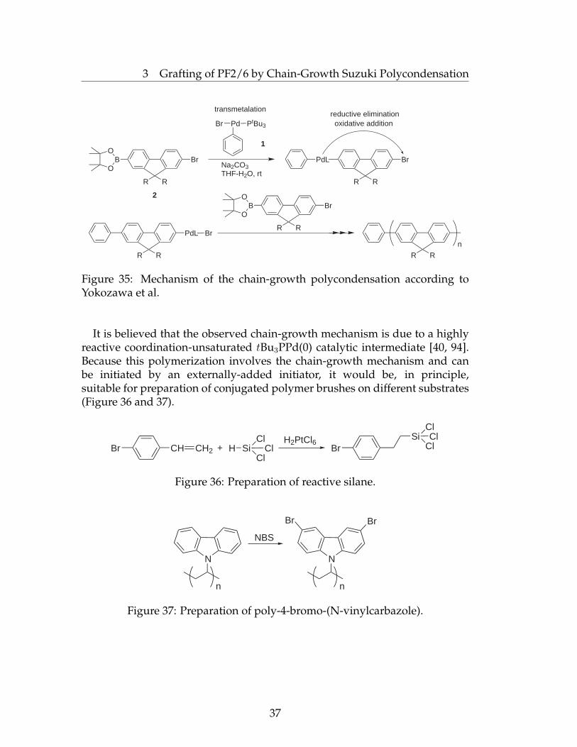
The expected polymerization mechanism is shown in Figure 35. Within theinitiation step, the initiator 1 is added to the first molecule of the monomer 2via transmetallation. As usually for Suzuki coupling, the next step is reductiveelimination which is responsible for liberation of the Pd(0) complex and theformation of a C-C bond between the phenyl group of the initiator andthe monomer residue. It is essential that the Pd(0) complex supported bya single bulky and electron-rich phosphorus ligand which does not diffusefrom the polymerizing chain but undergoes oxidative addition to the nearestC-Br bond located in the newly added monomer unit. Thus, intramolecularoxidative addition has been found to be a more favourable pathway thanthe intermolecular one. The addition of new monomer molecules to thepolymerizing chain end occurs in a one-by-one manner, typical chain-growthpolymerizations. Due to the peculiarity of this mechanism, most of thepolyfluorene chains formed upon the polycondensation have phenyl startinggroups which were transferred from the initiator and present.
36
3 Grafting of PF2/6 by Chain-Growth Suzuki Polycondensation
BO
OBr
R R
R R
PdL Br
Pd PtBu3Br
BO
OBr
R R
PdL
R R
Br
R R
Na2CO3THF-H2O, rt
n
2
transmetalation
oxidative additionreductive elimination
1
Figure 35: Mechanism of the chain-growth polycondensation according toYokozawa et al.
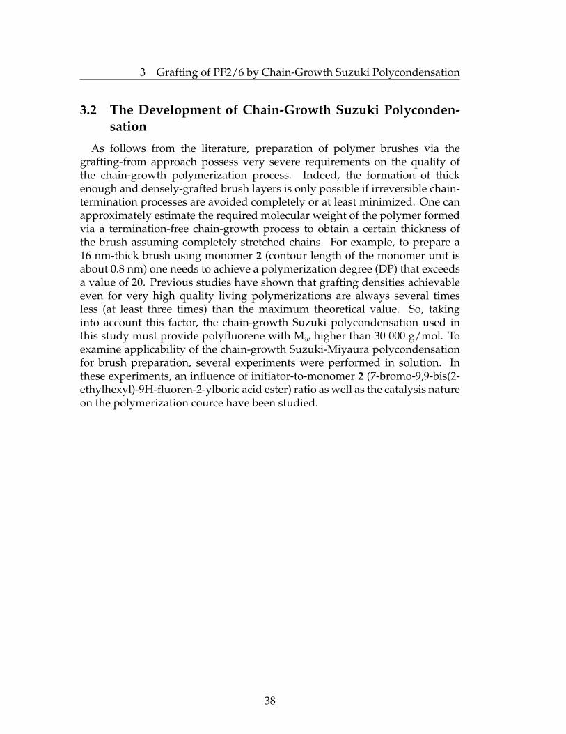
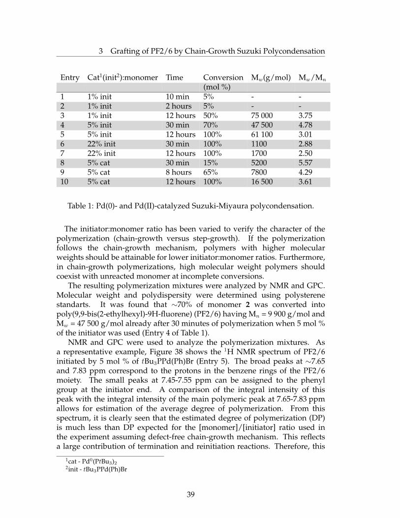
It is believed that the observed chain-growth mechanism is due to a highlyreactive coordination-unsaturated tBu3PPd(0) catalytic intermediate [40, 94].Because this polymerization involves the chain-growth mechanism and canbe initiated by an externally-added initiator, it would be, in principle,suitable for preparation of conjugated polymer brushes on different substrates(Figure 36 and 37).
Br CH CH2 SiHCl
ClCl
H2PtCl6Br
Si ClCl
Cl
+
Figure 36: Preparation of reactive silane.
N
NBS
N
BrBr
n n
Figure 37: Preparation of poly-4-bromo-(N-vinylcarbazole).
37
3 Grafting of PF2/6 by Chain-Growth Suzuki Polycondensation
3.2 The Development of Chain-Growth Suzuki Polyconden-sation
As follows from the literature, preparation of polymer brushes via thegrafting-from approach possess very severe requirements on the quality ofthe chain-growth polymerization process. Indeed, the formation of thickenough and densely-grafted brush layers is only possible if irreversible chain-termination processes are avoided completely or at least minimized. One canapproximately estimate the required molecular weight of the polymer formedvia a termination-free chain-growth process to obtain a certain thickness ofthe brush assuming completely stretched chains. For example, to prepare a16 nm-thick brush using monomer 2 (contour length of the monomer unit isabout 0.8 nm) one needs to achieve a polymerization degree (DP) that exceedsa value of 20. Previous studies have shown that grafting densities achievableeven for very high quality living polymerizations are always several timesless (at least three times) than the maximum theoretical value. So, takinginto account this factor, the chain-growth Suzuki polycondensation used inthis study must provide polyfluorene with Mw higher than 30 000 g/mol. Toexamine applicability of the chain-growth Suzuki-Miyaura polycondensationfor brush preparation, several experiments were performed in solution. Inthese experiments, an influence of initiator-to-monomer 2 (7-bromo-9,9-bis(2-ethylhexyl)-9H-fluoren-2-ylboric acid ester) ratio as well as the catalysis natureon the polymerization cource have been studied.
38
3 Grafting of PF2/6 by Chain-Growth Suzuki Polycondensation
Entry Cat1(init2):monomer Time Conversion Mw(g/mol) Mw/Mn
(mol %)1 1% init 10 min 5% - -2 1% init 2 hours 5% - -3 1% init 12 hours 50% 75 000 3.754 5% init 30 min 70% 47 500 4.785 5% init 12 hours 100% 61 100 3.016 22% init 30 min 100% 1100 2.887 22% init 12 hours 100% 1700 2.508 5% cat 30 min 15% 5200 5.579 5% cat 8 hours 65% 7800 4.2910 5% cat 12 hours 100% 16 500 3.61
Table 1: Pd(0)- and Pd(II)-catalyzed Suzuki-Miyaura polycondensation.
The initiator:monomer ratio has been varied to verify the character of thepolymerization (chain-growth versus step-growth). If the polymerizationfollows the chain-growth mechanism, polymers with higher molecularweights should be attainable for lower initiator:monomer ratios. Furthermore,in chain-growth polymerizations, high molecular weight polymers shouldcoexist with unreacted monomer at incomplete conversions.
The resulting polymerization mixtures were analyzed by NMR and GPC.Molecular weight and polydispersity were determined using polysterenestandarts. It was found that ∼70% of monomer 2 was converted intopoly(9,9-bis(2-ethylhexyl)-9H-fluorene) (PF2/6) having Mn = 9 900 g/mol andMw = 47 500 g/mol already after 30 minutes of polymerization when 5 mol %of the initiator was used (Entry 4 of Table 1).
NMR and GPC were used to analyze the polymerization mixtures. Asa representative example, Figure 38 shows the 1H NMR spectrum of PF2/6initiated by 5 mol % of tBu3PPd(Ph)Br (Entry 5). The broad peaks at ∼7.65and 7.83 ppm correspond to the protons in the benzene rings of the PF2/6moiety. The small peaks at 7.45-7.55 ppm can be assigned to the phenylgroup at the initiator end. A comparison of the integral intensity of thispeak with the integral intensity of the main polymeric peak at 7.65-7.83 ppmallows for estimation of the average degree of polymerization. From thisspectrum, it is clearly seen that the estimated degree of polymerization (DP)is much less than DP expected for the [monomer]/[initiator] ratio used inthe experiment assuming defect-free chain-growth mechanism. This reflectsa large contribution of termination and reinitiation reactions. Therefore, this
1cat - Pd0(PtBu3)22init - tBu3PPd(Ph)Br
39
3 Grafting of PF2/6 by Chain-Growth Suzuki Polycondensation
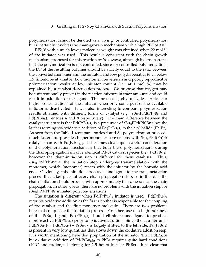
polymerization cannot be denoted as a "living" or controlled polymerizationbut it certainly involves the chain-growth mechanism with a high PDI of 3.01.
PF2/6 with a much lower molecular weight was obtained when 22 mol %of the initiator was used. This result is consistent with the chain-growthmechanism, proposed for this reaction by Yokozawa, although it demonstratesthat the polymerization is not controlled, since for controlled polymerizationsthe DP of the resulting polymer should be strictly equal to the ratio betweenthe converted monomer and the initiator, and low polydispersities (e.g., below1.5) should be attainable. Low monomer conversions and poorly reproduciblepolymerization results at low initiator content (i.e., at 1 mol %) may beexplained by a catalyst deactivation process. We propose that oxygen maybe unintentionally present in the reaction mixture in trace amounts and couldresult in oxidation of the ligand. This process is, obviously, less critical forhigher concentrations of the initiator when only some part of the availableinitiator is deactivated. It was also interesting to compare polymerizationresults obtained with different forms of catalyst (e.g., tBu3PPd(Ph)Br andPd(PtBu3)2, entries 4 and 8 respectively). The main difference between thecatalyst structure is that Pd(PtBu3)2 is a precursor of tBu3PPd(Ph)Br since thelater is forming via oxidative addition of Pd(PtBu3)2 to the aryl halide (Ph-Br).As seen from the Table 1 (compare entries 4 and 8), polymerization proceedsmuch faster and provides higher monomer conversions with tBu3PPd(Ph)Brcatalyst than with Pd(PtBu3)2. It becomes clear upon careful considerationof the polymerization mechanism that both these polymerizations duringthe chain-propagation involve identical Pd(0) catalyst species (i.e., PdPtBu3),however the chain-initiation step is different for these catalysts. Thus,tBu3PPd(Ph)Br at the initiation step undergoes transmetalation with themonomer, which (monomer) reacts with the initiator by the boronic acidend. Obviously, this initiation process is analogous to the transmetalationprocess that takes place at every chain-propagation step, so in this case thechain-initiation should proceed with approximately the same rate as the chainpropagation. In other words, there are no problems with the initiation step fortBu3PPd(Ph)Br initiated polycondensations.
The situation is different when Pd(PtBu3)2 initiator is used. Pd(PtBu3)2
requires oxidative addition as the first step that is responsible for the couplingof the catalyst and the first monomer molecule. There are two problemshere that complicate the initiation process. First, because of a high bulkinessof the PtBu3 ligand, Pd(PtBu3)2 should eliminate one ligand to producemore reactive Pd(PtBu3) prior to oxidative addition. Since the equilibrium -Pd(PtBu3)2 = Pd(PtBu3) + PtBu3 - is largely shifted to the left side, Pd(PtBu3)is present in very low quantities that slows down the oxidative addition step.It is worth mentioning here that preparation of the initiator tBu3PPd(Ph)Brby oxidative addition of Pd(PtBu3)2 to PhBr requires quite hard conditions(70◦C and prolonged stirring for 2.5 hours in neat PhBr). It is clear that
40

3 Grafting of PF2/6 by Chain-Growth Suzuki Polycondensation
this reaction would proceed even slower at polymerization conditions (roomtemperature and lower concentration of the aryl halide). On the other hand,oxidative addition of Pd(PtBu3)2 to the C-Br bound of the monomer seemsto be even more problematic process than the oxidative addition to PhBrbecause of electron-donating character of boronic acid group in the monomer.As a result, Pd(PtBu3)2 is not efficient initiator for Suzuki polycondensation.This result has very important practical implications since it shows in whichform palladium catalyst must be introduced into polymerization mixture toefficiently initiate polymerization. It is noteworthy that this issue is much lessimportant for "classical" catalysts, e.g., Pd supported by PPh3, which can beintroduced into polymerization in a very different forms (e.g., PdCl2(PPh3)2 orPd2(dba)3 + PPh3, etc.) with an approximately equal polymerization results.
n1
2 3 4 5
6
Chemical shift (ppm)
8.10 8.00 7.90 7.80 7.70 7.60 7.50 7.40 7.30
3,4
1,2,5,6
8.0 7.0 6.0 5.0 4.0 3.0 2.0 1.0
Chemical shift (ppm)
Figure 38: NMR spectrum of PF2/6 grown from adduct of bromobenzene andPd(PtBu3)2 in chloroform-d.
What is important for the main task of this work is that the conductedexperiments showed the general feasibility of rapid polymerization of 2 intoPF2/6 with a relatively high MW. The latter might be limited by the solubilityof the polymer in the water-saturated reaction mixture, as shown by Yokozawaet al. and follows from our experiments. This factor of limited solubility mightbe less critical for surface-initiated polymerization (SIP), when the growingsurface-bound chains are more stretched and are therefore less prone to foldback upon the aggregation to hide the growing end-points. This would lead to
41
3 Grafting of PF2/6 by Chain-Growth Suzuki Polycondensation
the formation of longer PF2/6 chains in the case of SIP than the polymerizationin solution. However, if the grafting process will provide MW similar to thoseobserved in the model bulk solution experiments, the thickness of the resultingbrushes should be quite low. Another conclusion from these experiments isthat polymerization is extremely sensitive to the presence of oxygen and it isespecially critical for a low concentration of the Pd initiator. Since the absoluteamount of the Pd initiator that could be immobilized on surface is even smallerthan in the model bulk solution experiments, additional measures should betaken to avoid the penetration of oxygen into polymerization vessels duringSIP.
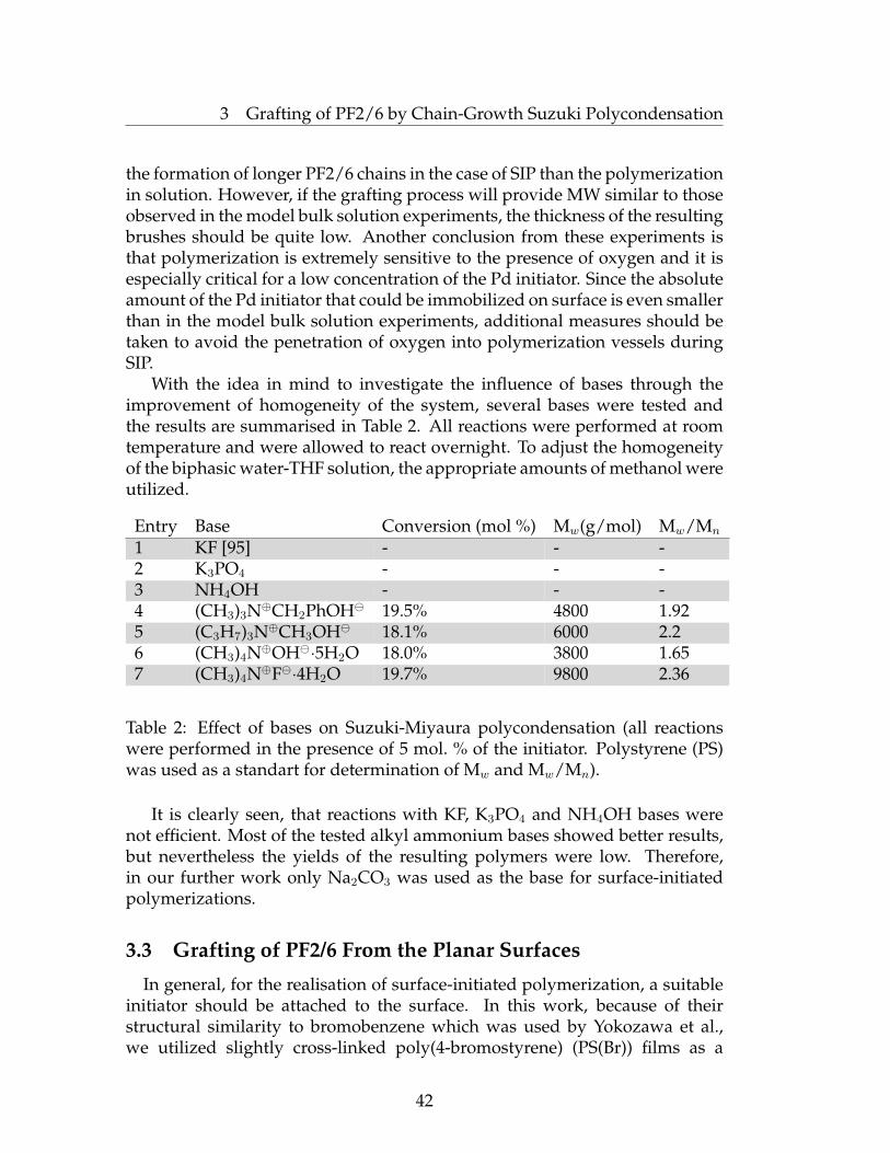
With the idea in mind to investigate the influence of bases through theimprovement of homogeneity of the system, several bases were tested andthe results are summarised in Table 2. All reactions were performed at roomtemperature and were allowed to react overnight. To adjust the homogeneityof the biphasic water-THF solution, the appropriate amounts of methanol wereutilized.
Entry Base Conversion (mol %) Mw(g/mol) Mw/Mn
1 KF [95] - - -2 K3PO4 - - -3 NH4OH - - -4 (CH3)3N⊕CH2PhOH 19.5% 4800 1.925 (C3H7)3N⊕CH3OH 18.1% 6000 2.26 (CH3)4N⊕OH·5H2O 18.0% 3800 1.657 (CH3)4N⊕F·4H2O 19.7% 9800 2.36
Table 2: Effect of bases on Suzuki-Miyaura polycondensation (all reactionswere performed in the presence of 5 mol. % of the initiator. Polystyrene (PS)was used as a standart for determination of Mw and Mw/Mn).
It is clearly seen, that reactions with KF, K3PO4 and NH4OH bases werenot efficient. Most of the tested alkyl ammonium bases showed better results,but nevertheless the yields of the resulting polymers were low. Therefore,in our further work only Na2CO3 was used as the base for surface-initiatedpolymerizations.
3.3 Grafting of PF2/6 From the Planar Surfaces
In general, for the realisation of surface-initiated polymerization, a suitableinitiator should be attached to the surface. In this work, because of theirstructural similarity to bromobenzene which was used by Yokozawa et al.,we utilized slightly cross-linked poly(4-bromostyrene) (PS(Br)) films as a
42

3 Grafting of PF2/6 by Chain-Growth Suzuki Polycondensation
precursor for the preparation of the macroinitiator. For the same reason,we have also focused our attention on the [2-(4-bromo-phenyl)-ethyl]-chloro-dimethyl-silane and poly-4-bromo(N-vinylcarbazole) supporting layers.
In the next step, we tried to perform SIP of 7-bromo-9,9-bis(2-ethylhexyl)-9H-fluoren-2-ylboric acid ester from activated surfaces. First, freshly cleanedsilica wafers were covered with a 2 nm thick poly(glycidyl methacrylate)(PGMA) layer, which was used as an adhesive layer. Then, the samples wereannealed at 150◦C for 2 hours to cross-link PGMA. Afterwards, PS(Br) wasspincoated from a toluene solution and slightly cross-linked by brief UV-lightirradiation. Typically, 10 nm thick photo cross-linked PS(Br) anchoring filmswere used. The substrates were placed vertically into a reactor and under anargon atmosphere a solution of Pd(PtBu3)2 was added. The tubes were heatedat 70◦C for 2.5 hours. The samples were then extensively washed with dryTHF under an argon atmosphere to remove unreacted Pd(PtBu3)2. Afterwards,the monomer was added in a degassed mixture of THF and aqueous sodiumcarbonate solution (Figure 39). The grafting experiments were conducted atroom temperature with stirring. The technical parameters were found to bevery important for successful grafting.
PGMA
Pd(L)Br
B BrO
O
R R
SiO2 SiO2
PGMA
R
Rn
PS(Br)PS(Br)
Figure 39: SIP of PF2/6 from PS(Br)-anchoring layer.
After very extensive stirring, almost no grafted PF2/6 was observed. Thiswas possibly due to the covering of the surface with water droplets, whichprevent the polymerization process. The greatest thicknesses of grafted PF2/6were achievable with gentle stirring that provided sufficient diffusion ofNa2CO3 dissolved in water. Only a marginal amount of water solution wasused; however, it was found to play a crucial role in the polymerizationprocess. No grafting of PF2/6 occured in those parts of the substrates which
43

3 Grafting of PF2/6 by Chain-Growth Suzuki Polycondensation
appeared to be in a direct contact with the water (bottom) phase of thebiphasic reaction mixture, possibly because of etching of the silicon and lowsolubility of the monomer in water. Under optimal conditions, the graftingprocedure resulted in uniform PF2/6 films with a thickness up to 50 nm, andin some cases up to 100 nm (Figure 40). The thickness measurements wereconducted by Null-ellipsometry and confirmed by the AFM cross-section test.Analysis of the AFM topography images of grafted PF2/6-films (Figure 41, a)revealed a root-mean-square roughness (RMS) of about 10 nm, whereas thestarting PGMA/PS(Br) layers were significantly smoother (RMS = 1.3 nm)(Figure 41, b). The grafting resulted in strongly adherent PF2/6 films,which were stable against extensive rinsing with various organic solventsin an ultrasonic bath or Soxhlet apparatus. Since the consumption of themonomer upon grafting is negligible, the reaction mixture can be used formany polymerizations. Importantly, an increase of the anchoring PS(Br) layerhad only a small positive effect on the grafting process (this issue is discussedin more detail below on page 50), suggesting that polycondensation proceedspredominantly from the topmost part of the PS(Br) film, in contrast to thepreviously reported Kumada SIP [1, 96, 97].
3.0µm
120
80
40
nm
0 1 2 3μm
Figure 40: AFM cross-section of the scratched area of a 100 nm thickPS(Br)-graft-PF2/6 brush film.
44
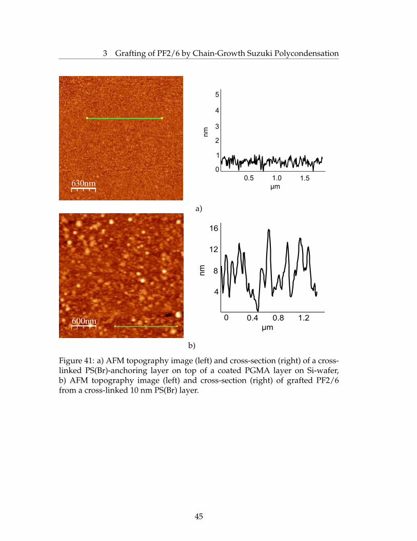
3 Grafting of PF2/6 by Chain-Growth Suzuki Polycondensation
630nm μm
0.5 1.0 1.5
nm
0
1
2
3
4
5
a)
600nmμm
nm
0 0.4 0.8 1.2
4
8
12
16
b)
Figure 41: a) AFM topography image (left) and cross-section (right) of a cross-linked PS(Br)-anchoring layer on top of a coated PGMA layer on Si-wafer,b) AFM topography image (left) and cross-section (right) of grafted PF2/6from a cross-linked 10 nm PS(Br) layer.
45
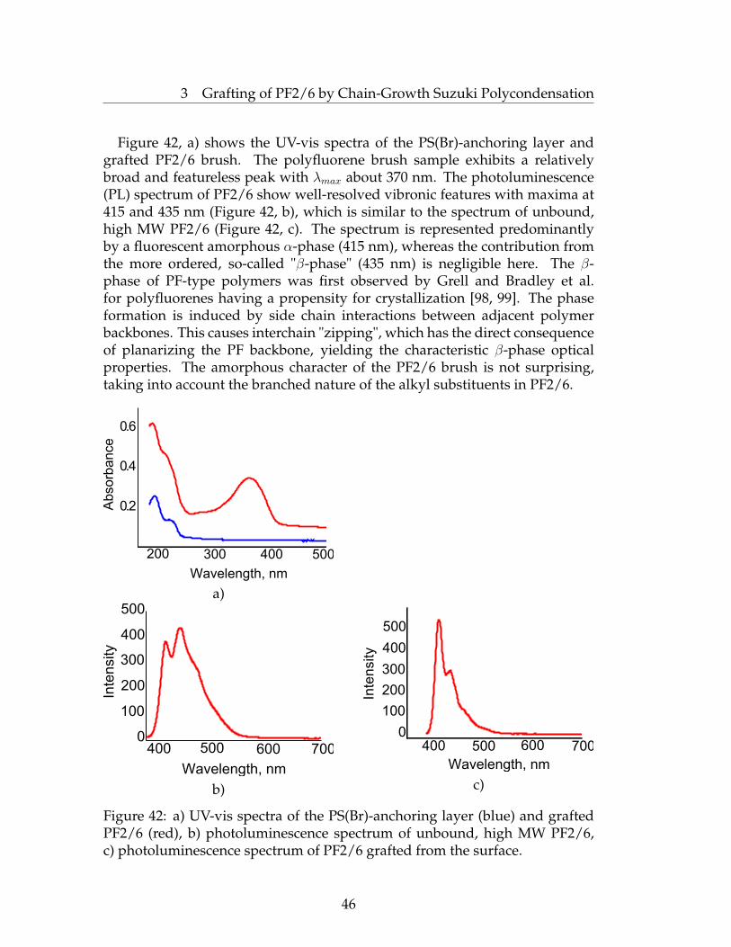
3 Grafting of PF2/6 by Chain-Growth Suzuki Polycondensation
Figure 42, a) shows the UV-vis spectra of the PS(Br)-anchoring layer andgrafted PF2/6 brush. The polyfluorene brush sample exhibits a relativelybroad and featureless peak with λmax about 370 nm. The photoluminescence(PL) spectrum of PF2/6 show well-resolved vibronic features with maxima at415 and 435 nm (Figure 42, b), which is similar to the spectrum of unbound,high MW PF2/6 (Figure 42, c). The spectrum is represented predominantlyby a fluorescent amorphous α-phase (415 nm), whereas the contribution fromthe more ordered, so-called "β-phase" (435 nm) is negligible here. The β-phase of PF-type polymers was first observed by Grell and Bradley et al.for polyfluorenes having a propensity for crystallization [98, 99]. The phaseformation is induced by side chain interactions between adjacent polymerbackbones. This causes interchain "zipping", which has the direct consequenceof planarizing the PF backbone, yielding the characteristic β-phase opticalproperties. The amorphous character of the PF2/6 brush is not surprising,taking into account the branched nature of the alkyl substituents in PF2/6.
0.2
0.4
0.6
Ab
so
rba
nce
Wavelength, nm
200 300 400 500
a)
0
Wavelength, nm
Inte
nsity
400 500 600 700
100
200
300
400
500
b)
0
Wavelength, nm
Inte
nsity
500
400
300
200
100
400 500 600 700
c)
Figure 42: a) UV-vis spectra of the PS(Br)-anchoring layer (blue) and graftedPF2/6 (red), b) photoluminescence spectrum of unbound, high MW PF2/6,c) photoluminescence spectrum of PF2/6 grafted from the surface.
46

3 Grafting of PF2/6 by Chain-Growth Suzuki Polycondensation
As evident from a fluorescent micrograph, the PF brushes display a strongemission in a dry state (Figure 43) that can be exploited in optoelectronicaldevices.
1 mm
Figure 43: Fluorescent micrograph of PF 2/6 grafted from 2 nm thick PS(Br)layer deposited on a quartz slide illuminated by UV-light lamp at 360 nm.
Alternatively, the substrate was coated with a 10 nm thick smooth(RMS = 1.32 nm) photo crosslinked poly-(4-bromo-vinylcarbazole), PVK(Br)film. PVK(Br) was used because the parent PVK is a semiconductor,possesses good hole-injection properties and is frequently used in OLEDs.The morphology of anchoring PVK(Br) layers deposited from differentsolvents was studied with AFM. It was found that PVK(Br) deposited froma dioxane solution (Figure 44) gave smoother films than ones formed fromtetrahydrofuran (Figure 45) or other solvents.
1.0µm
nm
μm
0 0.5 1 1.5 2 2.50
0.5
1
1.5
2
Figure 44: AFM topography image and cross-section of the 10 nm thick (asdetermined using ellipsometry) PVK(Br) film on a Si-wafer substrate coveredwith 2 nm thick PGMA. PVK(Br) was deposited from a dioxane solution.
47
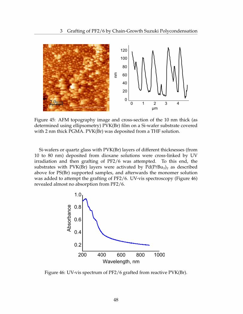
3 Grafting of PF2/6 by Chain-Growth Suzuki Polycondensation
2.0µm 0 1 2 3 4
μm
nm
0
20
40
60
80
100
120
Figure 45: AFM topography image and cross-section of the 10 nm thick (asdetermined using ellipsometry) PVK(Br) film on a Si-wafer substrate coveredwith 2 nm thick PGMA. PVK(Br) was deposited from a THF solution.
Si-wafers or quartz glass with PVK(Br) layers of different thicknesses (from10 to 80 nm) deposited from dioxane solutions were cross-linked by UVirradiation and then grafting of PF2/6 was attempted. To this end, thesubstrates with PVK(Br) layers were activated by Pd(PtBu3)2 as describedabove for PS(Br) supported samples, and afterwards the monomer solutionwas added to attempt the grafting of PF2/6. UV-vis spectroscopy (Figure 46)revealed almost no absorption from PF2/6.
Abso
rba
nce
Wavelength, nm
200 400 600 800 1000
0.2
0.4
0.6
0.8
1.0
Figure 46: UV-vis spectrum of PF2/6 grafted from reactive PVK(Br).
48

3 Grafting of PF2/6 by Chain-Growth Suzuki Polycondensation
Fluorescence spectrum (Figure 47, b) detected the emission peak assignableto PF2/6 with rather low intensity. Ellipsometry showed that the filmthicknesses as well as surface morphology remained practically unchangedafter these attempts (Figure 48). These facts imply that almost no grafting ofPF2/6 occurs if PVK(Br) is used as the supporting layer.
Wavelength, nm
Inte
nsity
400 450 500 550 600
30
40
50
60
70
80
a)
Inte
nsity
Wavelength, nm
0
40
80
120
160
400 450 500 550 600
b)
Figure 47: Fluorescence spectra of a) the PVK(Br)-anchoring layer andb) PF2/6 grafted from PVK(Br).
49
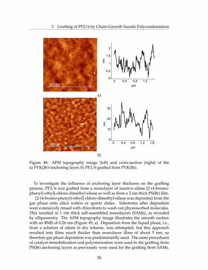
3 Grafting of PF2/6 by Chain-Growth Suzuki Polycondensation
600nm
nm
μm
0
0.5
1
1.5
2
0 0.4 0.8 1.2
a)
600nm
nm
μm
0
10
20
30
0 0.4 0.8 1.2 1.6
b)
Figure 48: AFM topography image (left) and cross-section (right) of thea) PVK(Br)-anchoring layer; b) PF2/6 grafted from PVK(Br).
To investigate the influence of anchoring layer thickness on the graftingprocess, PF2/6 was grafted from a monolayer of reactive silane [2-(4-bromo-phenyl)-ethyl]-chloro-dimethyl-silane as well as from a 2 nm thick PS(Br) film.
[2-(4-bromo-phenyl)-ethyl]-chloro-dimethyl-silane was deposited from thegas phase onto silica wafers or quartz slides. Substrates after depositionwere extensively rinsed with chloroform to wash out physiosorbed molecules.This resulted in 1 nm thick self-assembled monolayers (SAMs), as revealedby ellipsometry. The AFM topography image illustrates the smooth surfacewith an RMS of 0.26 nm (Figure 49, a). Deposition from the liquid phase, i.e.,from a solution of silane in dry toluene, was attempted, but this approachresulted into films much thicker than monolayer films of about 5 nm, sotherefore gas phase deposition was predominantly used. The same proceduresof catalyst immobilization and polymerization were used in the grafting fromPS(Br) anchoring layers as previously were used for the grafting from SAMs.
50
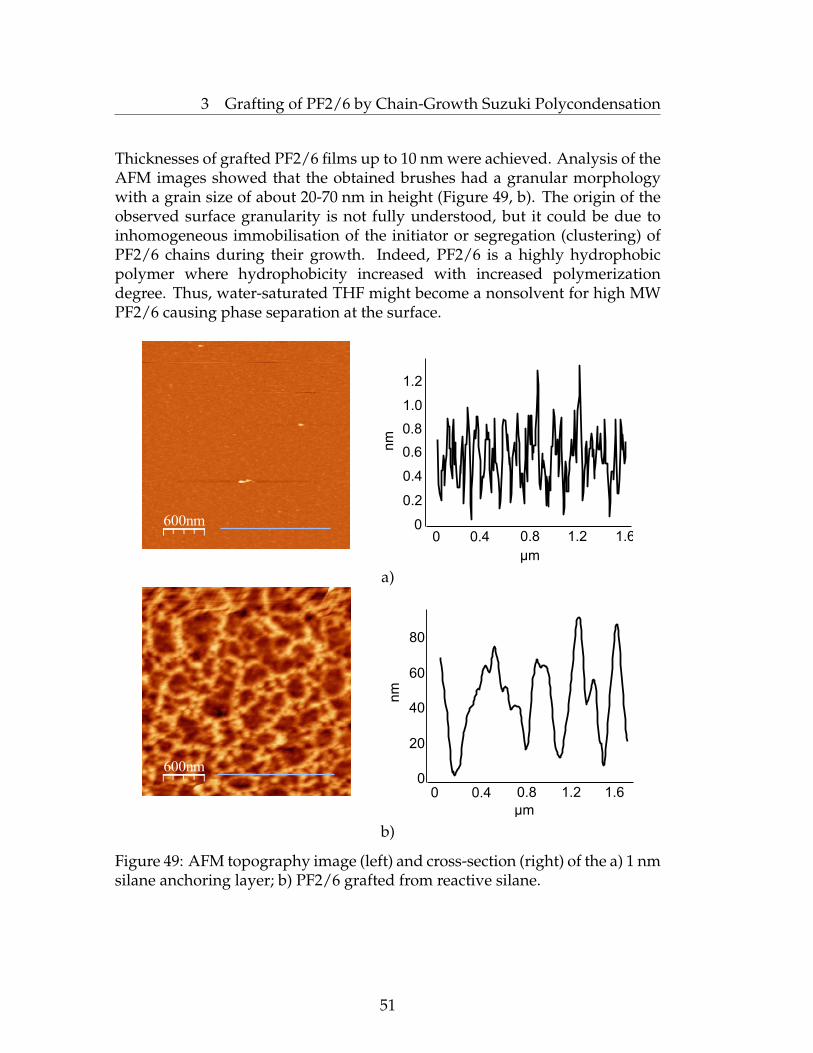
3 Grafting of PF2/6 by Chain-Growth Suzuki Polycondensation
Thicknesses of grafted PF2/6 films up to 10 nm were achieved. Analysis of theAFM images showed that the obtained brushes had a granular morphologywith a grain size of about 20-70 nm in height (Figure 49, b). The origin of theobserved surface granularity is not fully understood, but it could be due toinhomogeneous immobilisation of the initiator or segregation (clustering) ofPF2/6 chains during their growth. Indeed, PF2/6 is a highly hydrophobicpolymer where hydrophobicity increased with increased polymerizationdegree. Thus, water-saturated THF might become a nonsolvent for high MWPF2/6 causing phase separation at the surface.
600nm
μm
nm
00
0.2
0.4
0.6
0.8
1.0
1.2
0.4 0.8 1.2 1.6
a)
600nm
μm
nm
0 0.4 0.8 1.2 1.60
20
40
60
80
b)
Figure 49: AFM topography image (left) and cross-section (right) of the a) 1 nmsilane anchoring layer; b) PF2/6 grafted from reactive silane.
51
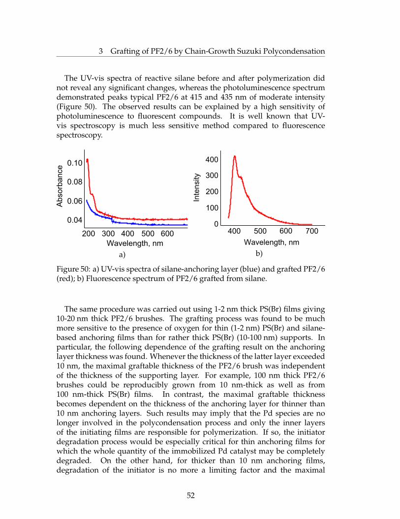
3 Grafting of PF2/6 by Chain-Growth Suzuki Polycondensation
The UV-vis spectra of reactive silane before and after polymerization didnot reveal any significant changes, whereas the photoluminescence spectrumdemonstrated peaks typical PF2/6 at 415 and 435 nm of moderate intensity(Figure 50). The observed results can be explained by a high sensitivity ofphotoluminescence to fluorescent compounds. It is well known that UV-vis spectroscopy is much less sensitive method compared to fluorescencespectroscopy.
Abso
rba
nce
Wavelength, nm
0.04
0.06
0.08
0.10
200 300 400 500 600
a)
Wavelength, nm
Inte
nsity
0
100
200
300
400
400 500 600 700
b)
Figure 50: a) UV-vis spectra of silane-anchoring layer (blue) and grafted PF2/6(red); b) Fluorescence spectrum of PF2/6 grafted from silane.
The same procedure was carried out using 1-2 nm thick PS(Br) films giving10-20 nm thick PF2/6 brushes. The grafting process was found to be muchmore sensitive to the presence of oxygen for thin (1-2 nm) PS(Br) and silane-based anchoring films than for rather thick PS(Br) (10-100 nm) supports. Inparticular, the following dependence of the grafting result on the anchoringlayer thickness was found. Whenever the thickness of the latter layer exceeded10 nm, the maximal graftable thickness of the PF2/6 brush was independentof the thickness of the supporting layer. For example, 100 nm thick PF2/6brushes could be reproducibly grown from 10 nm-thick as well as from100 nm-thick PS(Br) films. In contrast, the maximal graftable thicknessbecomes dependent on the thickness of the anchoring layer for thinner than10 nm anchoring layers. Such results may imply that the Pd species are nolonger involved in the polycondensation process and only the inner layersof the initiating films are responsible for polymerization. If so, the initiatordegradation process would be especially critical for thin anchoring films forwhich the whole quantity of the immobilized Pd catalyst may be completelydegraded. On the other hand, for thicker than 10 nm anchoring films,degradation of the initiator is no more a limiting factor and the maximal
52

3 Grafting of PF2/6 by Chain-Growth Suzuki Polycondensation
thickness of grafted PF2/6 is controlled by other processes, such as by chain-termination reactions.
3.4 Kinetic Studies
To analyze the kinetics of the grafting process, eight Si-wafers and eightquartz slides were each coated with 2 nm thick PS(Br) anchoring layersand polymerization was conducted for different times, from 0.5 to 60 hours,under otherwise identical conditions. We found that the resulting PF2/6films reached a thickness of ∼30 nm already within 30 minutes of thepolymerization, and approached maximal thicknesses within the first hour ofpolymerization (Figure 51).
Th
ickn
ess, n
m
Time, hours
0 10 20 30 40 50 60
30
35
40
45
50
Figure 51: Kinetics of the PF2/6 grafting process.
Such results are consistent with bulk solution polymerization experimentswith PF2/6 for which rather high molecular weight PF2/6 of 45 000 g/molformed within 30 minutes of the polymerization.
3.5 Grafting of PF2/6 from Silica Nanoparticles
To confirm that the prepared grafted films are indeed brush-like structuresand not a cross-linked PF2/6-network, degrafting of surface-immobilisedPF2/6 and their analysis would be advisable. It is, however, clear that forthe collection of a quantity of the polymer material necessary for standardinvestigations like GPC or NMR, graft-polymerization should be formed onquite a large substrate (in the order of one square meter), which is nottechnically feasible. To circumvent this problem, we attempted SIP of PF2/6from modified submicrometre organosilica particles that would mimic planarsubstrates. Because of a high surface-to-volume ratio for microparticles, it was
53

3 Grafting of PF2/6 by Chain-Growth Suzuki Polycondensation
feasible to collect the necessary amount of degrafted material from a singleexperiment. Other benefits of using these microparticles are as follows: nearlymonodisperse silica spheres of controlled size and surface chemistry are easilyavailable by a Stöber method [100]; the relatively large size and high density ofthe particles facilitate separation of surface-grafted materials from ungraftedones by a simple centrifugation procedure; silica particles can be selectivelyetched under mild conditions without the destruction of attached polymers,and therefore, the grafted polymers can be released from the support forfurther analysis. This is in a contrast to the case when planar surfaces areused as supports.
Silica-core organosilica-shell particles,∼300 nm in diameter, were preparedby a modified Stöber method [101] via sequential sol-gel hydrolysis oftetramethyl orthosilicates (TMOS) and [2-(4-bromo-phenyl)-ethyl]-triethoxy-silane under controlled conditions (Figure 52). Organosilane was obtained bystandard hydrosililation of 4-bromostyrene by triethoxisilane in the presenceof a chloroplatinic acid catalyst, and was used in the synthesis of particlesto introduce bromophenyl surface-functionality which is necessary for theimmobilisation of the Pd catalyst.
Br
Figure 52: Stöber synthesis of functionalized silica nanoparticles.
Grafting of PF was attempted by the activation of the reactive nanoparticlesurface with Pd(PtBu3)2 followed by the SIP process. The prepared particleswith an organosilica core and a PF2/6 shell were extensively characterized.
54

3 Grafting of PF2/6 by Chain-Growth Suzuki Polycondensation
SEM measurements revealed that the SIP attempt resulted in a significantincrease in the roughness of the particles surface instead of an increase indiameter (Figure 53), which was probably due to the unavoidable wetting andetching of the particles by the basic water phase during the polymerizationprocess and suppression of the grafting-from process. Additionally, due to thepartial wetting of the particles, they tended to coagulate which also causedineffective grafting.
a)
b)
Figure 53: SEM-images of functionalized silica particles a) before SIP; b) afterSIP.
55

3 Grafting of PF2/6 by Chain-Growth Suzuki Polycondensation
The photoluminescence spectrum of PF2/6-SiO2 nanoparticles showed alow-intensity and relatively well-structured peak at 420 nm with a shoulderat 440 nm (Figure 54, b). The indistinctness of this spectrum reflectsthe permanent diffusion of nanoparticles in the dispersion. Fluorescentmicroscopy also detected agglomerated nanoparticles that emitted light in theblue region (Figure 54, a). However, fluorescence intensity was relatively lowsuggesting an inefficient grafting process.
a)
Inte
nsity
Wavelength, nm
0
100
200
300
400 420 440 460 480 500
b)
Figure 54: a) Fluorescent micrograph of of Si-graft-PF2/6 nanoparticlesdeposited on a quartz slide illuminated by UV-light lamp at 360 nm;b) Photoluminescence spectrum of Si-particles after polymerization.
We tried to investigate the thermal behavior of the silica nanoparticlesbefore and after polycondensation by thermogravimetry. Unfortunately, TGAanalysis of the PF2/6-SiO2 particles did not reveal any significant changescompared to initial particles. We thus concluded that only negligible amountsof PF2/6 were grafted to the nanoparticles.
For analytical purposes, grafted PF2/6 chains were detached from the silicacore of the SiO2-PF2/6 particles by dissolution of the latter in a mixture of
56
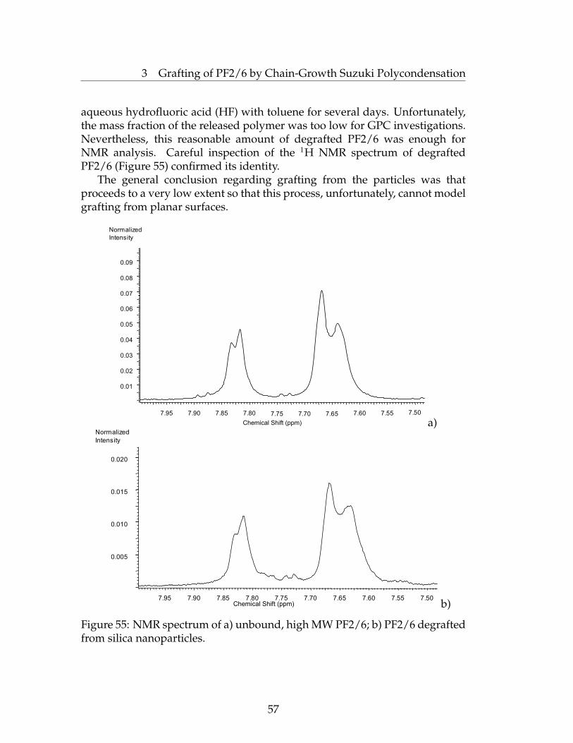
3 Grafting of PF2/6 by Chain-Growth Suzuki Polycondensation
aqueous hydrofluoric acid (HF) with toluene for several days. Unfortunately,the mass fraction of the released polymer was too low for GPC investigations.Nevertheless, this reasonable amount of degrafted PF2/6 was enough forNMR analysis. Careful inspection of the 1H NMR spectrum of degraftedPF2/6 (Figure 55) confirmed its identity.
The general conclusion regarding grafting from the particles was thatproceeds to a very low extent so that this process, unfortunately, cannot modelgrafting from planar surfaces.
Chemical Shift (ppm)
7.95 7.90 7.85 7.80 7.75 7.70 7.65 7.60 7.55 7.50
0.01
0.02
0.03
0.04
0.05
0.06
0.07
0.08
0.09
Normalized
Intensity
a)
Chemical Shift (ppm)7.95 7.90 7.85 7.80 7.75 7.70 7.65 7.60 7.55 7.50
0.005
0.010
0.015
0.020
Normalized
Intensity
b)
Figure 55: NMR spectrum of a) unbound, high MW PF2/6; b) PF2/6 degraftedfrom silica nanoparticles.
57
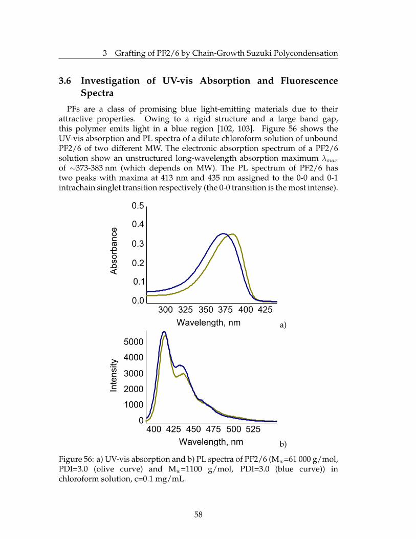
3 Grafting of PF2/6 by Chain-Growth Suzuki Polycondensation
3.6 Investigation of UV-vis Absorption and FluorescenceSpectra
PFs are a class of promising blue light-emitting materials due to theirattractive properties. Owing to a rigid structure and a large band gap,this polymer emits light in a blue region [102, 103]. Figure 56 shows theUV-vis absorption and PL spectra of a dilute chloroform solution of unboundPF2/6 of two different MW. The electronic absorption spectrum of a PF2/6solution show an unstructured long-wavelength absorption maximum λmaxof ∼373-383 nm (which depends on MW). The PL spectrum of PF2/6 hastwo peaks with maxima at 413 nm and 435 nm assigned to the 0-0 and 0-1intrachain singlet transition respectively (the 0-0 transition is the most intense).
Abso
rba
nce
Wavelength, nm
0.0
0.1
0.2
0.3
0.4
0.5
300 325 350 375 400 425
a)
Inte
nsity
Wavelength, nm
0
1000
2000
3000
4000
5000
400 425 450 475 500 525
b)
Figure 56: a) UV-vis absorption and b) PL spectra of PF2/6 (Mw=61 000 g/mol,PDI=3.0 (olive curve) and Mw=1100 g/mol, PDI=3.0 (blue curve)) inchloroform solution, c=0.1 mg/mL.
58
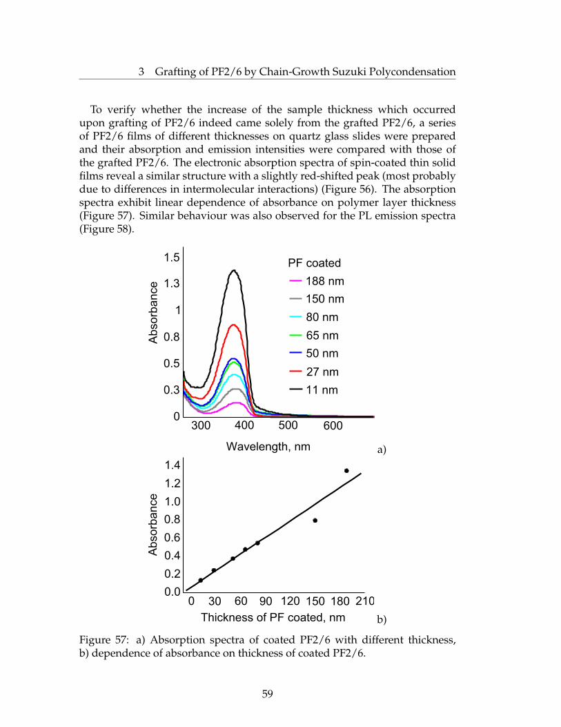
3 Grafting of PF2/6 by Chain-Growth Suzuki Polycondensation
To verify whether the increase of the sample thickness which occurredupon grafting of PF2/6 indeed came solely from the grafted PF2/6, a seriesof PF2/6 films of different thicknesses on quartz glass slides were preparedand their absorption and emission intensities were compared with those ofthe grafted PF2/6. The electronic absorption spectra of spin-coated thin solidfilms reveal a similar structure with a slightly red-shifted peak (most probablydue to differences in intermolecular interactions) (Figure 56). The absorptionspectra exhibit linear dependence of absorbance on polymer layer thickness(Figure 57). Similar behaviour was also observed for the PL emission spectra(Figure 58).
Wavelength, nm
Abso
rba
nce
0
0.3
0.5
0.8
1
1.3
1.5
300 400 500 600
PF coated
188 nm
150 nm
65 nm
80 nm
50 nm
27 nm
11 nm
a)
Abso
rba
nce
Thickness of PF coated, nm
0.0
0.2
0.4
0.6
0.8
1.0
1.2
1.4
0 30 60 90 120 150 180 210
b)
Figure 57: a) Absorption spectra of coated PF2/6 with different thickness,b) dependence of absorbance on thickness of coated PF2/6.
59

3 Grafting of PF2/6 by Chain-Growth Suzuki Polycondensation
PF coated
188 nm
150 nm
65 nm
80 nm
50 nm
27 nm
11 nm
Flu
ore
sce
nce
Inte
nsity
Wavelength, nm
400 450 500 5500
100
200
300
400
500
a)
Flu
ore
sce
nce
In
ten
sity
Thickness of PF coated, nm
0 50 100 150 200
100
200
300
400
500
b)
Figure 58: a) Emission spectra of coated PF2/6 with different thickness,b) dependence of intensity on the thickness of coated PF2/6.
It was found that absorption spectra of the grafted PF2/6 films in thedry state and in chloroform (a "good solvent") (Figure 59) are similar tothe aforementioned spectrum of unbound PF2/6 (Figure 56). Moreover, theabsorption intensity for the grafted films approaches to the one for spin-coatedPF2/6 of the same thickness (Figure 57, b) and these data confirm that thegrafted material is namely PF2/6.
60

3 Grafting of PF2/6 by Chain-Growth Suzuki Polycondensation
Ab
so
rba
nce
Wavelength, nm
0.00
0.05
0.10
0.15
0.20
0.25
350 400 450 500
Figure 59: Absorption spectra of grafted PF2/6 in the dry state (red) and inchloroform (violet).
To investigate the dependence of PL intensity on the media, we measuredspectra in different solvents (Figure 60). As expected, the highest fluorescenceintensity of the grafted PF2/6 was observed for films immersed in CHCl3,which is a good solvent for PF2/6. The emission intensity in THF wasapproximately two-fold less, whereas the intensity in methanol was one orderof magnitude less than the intensity in CHCl3, most likely due to reducedquality of the solvents. The lowest fluorescence intensity (∼5% of the intensityin CHCl3) was found for grafted PF2/6 films in the dry state, likely due toan aggregation of PF2/6 chains caused by a well-known self-quenching effect.(The more polar solvent molecules are more closely bound to the excited state,and this favours non-radiative deactivation processes.)
Inte
nsity
Wavelength, nm
400 450 500 550 600
0
200
400
600
800
1000
1200
Figure 60: Fluorescence spectra of the 40 nm thick PF2/6 film grafted from2 nm thick PS(Br) in different solvents (blue - in chloroform, violet - in THF,brown - in methanol, green - in the dry state).
61

3 Grafting of PF2/6 by Chain-Growth Suzuki Polycondensation
The major problem in the application of PFs in blue PLEDs is colorinstability. The pure blue emission can be contaminated by an undesiredcontribution of the green emission band (∼530 nm). It was shown by List andco-workers that the green emission of PF is due to fluoren-9-one defects in thepolymer chain [104, 105, 106].
Inte
nsity
Wavelength, nm
400 450 500 550 600 650 700
0
300
600
900
1200
1500
Figure 61: Fluorescence spectrum of the 40 nm thick PF2/6 film grafted from2 nm thick PS(Br), after annealing at 200◦C for 2 hours in air.
The surface-grafted PF2/6 did not exhibit degradation upon storage incontact with air for at least three months. However, air annealing of thesamples at 200◦C lead to the appearance of a characteristic green emission(Figure 61), presumably due to the formation of fluorenone-defects (λmax = 522nm) in the PF2/6 structure (Figure 63). The green emission was stronger inthe dry state, much lower in THF and is completely suppressed in CHCl3)(Figure 62).
Wavelength, nm
Inte
nsity
400 450 500 550 600 650 7000
300
600
900
1200
1500
Figure 62: Fluorescence spectra of the 40 nm thick PF2/6 film grafted from2 nm thick PS(Br) aged for 2 hours at 200◦C (blue - in chloroform, violet - inTHF, brown - in methanol, green - in the dry state).
62

3 Grafting of PF2/6 by Chain-Growth Suzuki Polycondensation
Possibly, keto-defects can trap created singlet excitons by dipole-dipoleinduced Forster-type [107] excitation energy transfer. This is a dominantprocess in the solid state, whereas in solution Forester-type energy transfer tothe keto-defect sites is diminished. The green emission recovers again after theevaporation of CHCl3 which indicates that this "green" emission results fromirreversible changes in the backbone chemical structure rather than solely fromthe chain-aggregation effect, although the green emission manifests itself to agreater extent for more aggregated PFs.
R
R OOH
R OO
O2
H R
O2
R
R OO
O
Figure 63: Simplified depiction of the mechanism of fluorenone formationfrom monosubstituted fluorene repeat units.
63

3 Grafting of PF2/6 by Chain-Growth Suzuki Polycondensation
3.7 Orientation Studies
The orientational order was studied using polarized UV-visible spec-troscopy at different angles. The highly stretch-oriented polymer chains mustshow strong anisotropy of absorbance parallel and perpendicular to the chaindirection. For this purpose the angular dependence was measured using aspectrometer with a step-width of 10◦. The investigated films did not revealany significant change in anisotropy, which means that the polymer chainspossess non-uniformly distributed orientation.
z
x
y
E
E
R R
x
y
Figure 64: a) Schematic working principle of utilized polarized spectroscopy;b) observed anisotropy of absorbance of grafted PF2/6 at different angles.
64
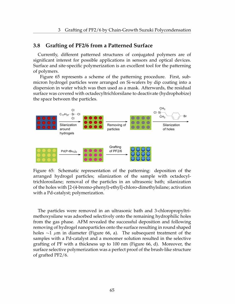
3 Grafting of PF2/6 by Chain-Growth Suzuki Polycondensation
3.8 Grafting of PF2/6 from a Patterned Surface
Currently, different patterned structures of conjugated polymers are ofsignificant interest for possible applications in sensors and optical devices.Surface and site-specific polymerization is an excellent tool for the patterningof polymers.
Figure 65 represents a scheme of the patterning procedure. First, sub-micron hydrogel particles were arranged on Si-wafers by dip coating into adispersion in water which was then used as a mask. Afterwards, the residualsurface was covered with octadecyltrichlorsilane to deactivate (hydrophobize)the space between the particles.
Si
Cl
Cl
C17H37 ClBr
Si
CH3
CH3
Cl
Pd(P-tBu3)2
Silanization
around
hydrogels
Removing of
particles
Silanization
of holes
Grafting
of PF2/6
Figure 65: Schematic representation of the patterning: deposition of thearranged hydrogel particles; silanization of the sample with octadecyl-trichlorosilane; removal of the particles in an ultrasonic bath; silanizationof the holes with [2-(4-bromo-phenyl)-ethyl]-chloro-dimethylsilane; activationwith a Pd-catalyst; polymerization.
The particles were removed in an ultrasonic bath and 3-chloropropyltri-methoxysilane was adsorbed selectively onto the remaining hydrophilic holesfrom the gas phase. AFM revealed the successful deposition and followingremoving of hydrogel nanoparticles onto the surface resulting in round shapedholes ∼1 µm in diameter (Figure 66, a). The subsequent treatment of thesamples with a Pd-catalyst and a monomer solution resulted in the selectivegrafting of PF with a thickness up to 100 nm (Figure 66, d). Moreover, thesurface selective polymerization was a perfect proof of the brush-like structureof grafted PF2/6.
65
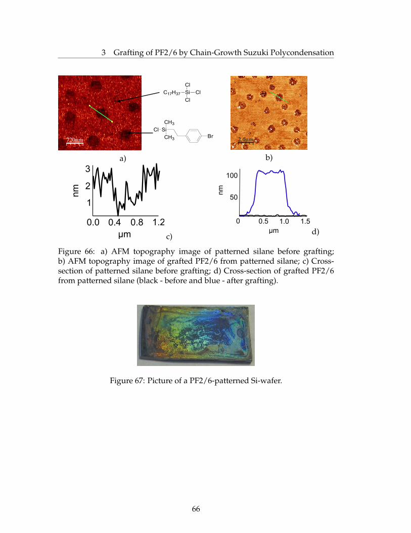
3 Grafting of PF2/6 by Chain-Growth Suzuki Polycondensation
Si
Cl
Cl
C17H37 Cl
Br
Si
CH3
CH3
Cl
720nm
a)
2.0µm
b)
0.0 0.4 0.8 1.2
1
2
3
μm
nm
c)μm
nm
0 0.5 1.0 1.5
50
100
d)
Figure 66: a) AFM topography image of patterned silane before grafting;b) AFM topography image of grafted PF2/6 from patterned silane; c) Cross-section of patterned silane before grafting; d) Cross-section of grafted PF2/6from patterned silane (black - before and blue - after grafting).
Figure 67: Picture of a PF2/6-patterned Si-wafer.
66

3 Grafting of PF2/6 by Chain-Growth Suzuki Polycondensation
3.9 Conclusions
In conclusion, we have developed the first surface-initiated and site-specificSuzuki polycondensation to fast and selectively grow polyfluorene fromproperly functionalized and patterned surfaces at room temperature. Thismethod seems to be very promising tool for fabrication of optoelectronicdevices and sensors.
3.10 Experimental Part
Materials. 4-Bromostyrene, Pd(PtBu3)2, 2,7-Dibromo-9,9-bis(2-ethylhexyl)-fluorene, pinacol, n-BuLi, bromobenzene, ammonium, hydrogen peroxide,toluene, hexane, ethanol, toluene, chloroform, dichloromethane, andtetrahydrofuran (THF, stabilizer free, anhydrous) were purchased fromAldrich and used as received without further purification. Poly(glycidylmethacrylate), PGMA (Mn=65 000 g/mol, PDI=2.05) was purchased fromPolymer Source Inc. Poly(4-bromostyrene) (Mn=51 000 g/mol, PDI=2.05) wasobtained via radical polymerization of 4-bromostyrene [108]. 7-Bromo-9,9-bis(2ethylhexyl)-9H-fluoren-2-ylboric acid ester [109] and tBu3PPd(Ph)Br wereprepared as previously described.
Preparation of [2-(4-bromo-phenyl)-ethyl]-chloro-dimethyl-silaneHydrosililation was carried out by adding dimethylchlorosilane (100 g)
to 4-bromostyrene (18.3 g, 0.1 mol) dropwise in the presence of 160 mg ofchloroplatinic acid (2 mL of 1:1 ethanol/diethyl ether solution) as a catalystand stirring for 1 h. After the excess of dimethylchlorsilane was removed byvacuum distillation, the only residue was fractionized by vacuum distillation.The resulting product is a mixture of Markovnikov and anti-Markovnikovadducts.
Grafting of PF2/6Highly polished Si-wafers (Wacker-Chemitronics), or quartz slides (Saint-
Gobain Quartz PLC.) were firstly cleaned in an ultrasonic bath three times for5 min with dichloromethane, placed in cleaning mixture of NH4OH:H2O2:H2O(1:1:2) at 80◦C for 1 h and finally rinsed several times with Milipore water(18 MQxcm).
PGMA layers of the same 2 nm thickness (ellipsometry data) were used inall experiments as adhesion promoter between PS(Br) and Si-substrates. It wasdeposited by spin-coating from chloroform (0.03 mg/ml, 2000 rpm) and thesamples were annealed at 150◦C during 2 hours in vacuum. PS(Br) layers withvariable thickness from 1 to 30 nm were spin-coated onto PGMA from tolueneand cross-linked upon a brief irradiation (from 3 to 15 seconds, depending
67

3 Grafting of PF2/6 by Chain-Growth Suzuki Polycondensation
on the PS(Br) thickness) with UV-light to achieve their insolubility, whilekeeping the films still swellable in "good" solvents for PS(Br). Alternatively[2-(4-bromo-phenyl)-ethyl]-chloro-dimethyl-silane was deposited from a gasphase onto Si-wafer or quartz slides. 0.1 ml of reactive silane was brought intodesiccator, the atmosphere was replaced with vacuum and the samples wereannealed at 60◦C during 2 hours. Afterwards the samples were extensivelyrinsed with toluene or chloroforme to remove non-reacted compounds, driedand placed into a round-bottomed flack equipped with septum, and theatmosphere was replaced with argon. Afterward, a solution of Pd(PtBu3)2
in dry toluene (3.5 ml, c = 3 mg/ml) was added to the flack in glovebox,and the samples were allowed to react for 2.5 hours at 70◦C. The reactionsolution was replaced with the mixture of solution of the monomer 2 in dryTHF (3.5 ml, c = 10 mg/ml) and 2M aqueous sodium carbonate (0.3 ml). Thesamples were allowed to polymerize at room temperature for 0.5-60 hours.To stop polymerization, the samples were moved from reactor and rinsedwith 2M HCl, water and hot organic solvents (acetone, CHCl3, hexane,THF). Independently on the thickness of the initiating layer, the resultingcomposit films were very robust against delamination upon extensive rinsingwith various different organic solvents in an ultrasonic bath and a Soxhletapparatus. This proves the covalent grafting of PF2/6.
Grafting of PF2/6 from silica nanoparticlesSilica-core organosilica-shell particles, ∼300 nm in the diameter, were pre-
pared by a modified Stöber method [101] via sequential sol-gel hydrolysis oftetramethyl orthosilicates (TMOS) and [2-(4-bromo-phenyl)-ethyl]-triethoxi-silane.
To immobilize the Pd catalyst, suspensions of silica particles in anhydrousand degassed toluene were mixed with Pd(PtBu3)2 in the same solventunder argon at 70◦C for 2.5 hours. Prior to polymerization, thus-treated particles were purified from unreacted Pd(PtBu3)2 by repeatedredispersion/centrifugation cycles. Grafting of PF was attempted by theaddition of the monomer 2 in degassed mixture of THF and aqueous sodiumcarbonate solution followed by stirring overnight. After quenching of thepolymerization mixture with 2M HCl, the particles were carefully purifiedfrom any ungrafted materials by redispersion in hot chloroform and THFfollowed by centrifugation. In addition, ethanol was used to remove waterresidue and allow better redispersion of particles.
68
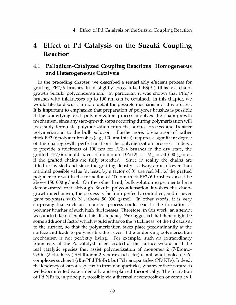
4 Effect of Pd Catalysis on the Suzuki Coupling Reaction
4 Effect of Pd Catalysis on the Suzuki CouplingReaction
4.1 Palladium-Catalyzed Coupling Reactions: Homogeneousand Heterogeneous Catalysis
In the preceding chapter, we described a remarkably efficient process forgrafting PF2/6 brushes from slightly cross-linked PS(Br) films via chain-growth Suzuki polycondensation. In particular, it was shown that PF2/6brushes with thicknesses up to 100 nm can be obtained. In this chapter, wewould like to discuss in more detail the possible mechanism of this process.It is important to emphasize that preparation of polymer brushes is possibleif the underlying graft-polymerization process involves the chain-growthmechanism, since any step-growth steps occurring during polymerization willinevitably terminate polymerization from the surface process and transferpolymerization to the bulk solution. Furthermore, preparation of ratherthick PF2/6 polymer brushes (e.g., 100 nm-thick), requires a significant degreeof the chain-growth perfection from the polymerization process. Indeed,to provide a thickness of 100 nm for PF2/6 brushes in the dry state, thegrafted PF2/6 should have of minimum DP=125 or Mw = 50 000 g/mol,if the grafted chains are fully stretched. Since in reality the chains aretitled or twisted and since the grafting density is always much lower thanmaximal possible value (at least, by a factor of 3), the real Mw of the graftedpolymer to result in the formation of 100 nm-thick PF2/6 brushes should beabove 150 000 g/mol. On the other hand, bulk solution experiments havedemonstrated that although Suzuki polycondensation involves the chain-growth mechanism, the process is far from perfectly controlled, and it nevergave polymers with Mw above 50 000 g/mol. In other words, it is verysurprising that such an imperfect process could lead to the formation ofpolymer brushes of such high thicknesses. Therefore, in this work, an attemptwas undertaken to explain this discrepancy. We suggested that there might besome additional factor which would enhance the "stickiness" of the Pd catalystto the surface, so that the polymerization takes place predominantly at thesurface and leads to polymer brushes, even if the underlying polymerizationmechanism is not perfectly living. For example, such an extraordinarypropensity of the Pd catalyst to be located at the surface would be if thereal catalytic species that assist polymerization of monomer 2 (7-Bromo-9,9-bis(2ethylhexyl)-9H-fluoren-2-ylboric acid ester) is not small molecule Pdcomplexes such as 1 (tBu3PPd(Ph)Br), but Pd nanoparticles (PD NPs). Indeed,the tendency of various species to form nanoparticles, whatever their nature, iswell-documented experimentally and explained theoretically. The formationof Pd NPs is, in principle, possible via a thermal decomposition of complex 1
69
4 Effect of Pd Catalysis on the Suzuki Coupling Reaction
during Pd catalyst immobilization or afterwards. On the other hand, if formed,such nanoparticles would indeed have an enhanced affinity to aryl- andaryl halide-terminated surfaces, such as PS(Br), because Pd NPs have manycoordination sites to bind several aryl halides at a time. The feasibility of thishypothesis is supported by the fact that Suzuki coupling catalyzed by Pd NPswhich are stabilized by phosphorous ligands is well-known (see below). Itis believed that the cross-coupling mechanism in this case is similar to thatfor reactions catalyzed by the usual small-molecule complexes, with the onlydifference that nanoparticles have a plurality of reaction sites with the localstructure similar to the structure of small-molecule catalysts. In the followingparagraphs, we will briefly review what is known to date about Suzukicross-coupling catalyzed by Pd NPs. We will further investigate in moredetail samples after immobilization of the Pd catalyst using XPS, TEM andNMR techniques in order to understand whether Pd nanoparticles are indeedformed in the activated layers. We will also describe independent synthesisof Pd NPs supported by different ligands and our attempts to catalyze Suzukipolycondensation in bulk solution and at surfaces using these nanoparticlesto mimic processes that take place upon surface-initiated polycondensation ofPF2/6 as described in Chapter 3.
Pd NPs are widely used as catalysts for Suzuki cross-coupling. The use ofNPs in catalysis allows for improving separation of the reaction products fromthe catalyst. This potentially facilitates decreased catalyst cost due to reducedcatalyst loss and simplified product purification [110, 111]. This is especiallycritical for the synthesis of medical compounds, which must contain�5 ppmof residual metal in the product [112].
El-Sayed and co-workers synthesized Pd NPs, stabilized by poly(vinylpyridine) (PVP) and studied their effectiveness in Suzuki reactions in anaqueous solution [113, 114, 115]. The detected TOF (turn off frequency) wasup to 90, whereas during the reaction course it decreased as the particlesize increased. That suggests that the Suzuki reaction is "structure-sensitive";that is, the low-coordination number vertex and edge atoms on the particlesurface are the active centres for catalysis. Primarily, PVP prevents coagulationof NPs, but the process of refluxing seems to cause Ostwald ripening (athermodynamically driven process that leads to the dissolution of small NPsand the growth of larger NPs) in which the size of NPs increases. Furthermore,they encapsulated NPs into poly(amidoamine) (PAMAM) dendrimers with3rd and 4th generations and studied their catalytic activity in the SuzukiC-C coupling reaction [116, 117]. Dendrimers stabilize the metal NPs bypreventing their agglomeration, but they do not fully passivate the metalsurface. Comparably with PVP-stabilized NPs, TOF was higher for thedendrimer-Pd NP catalyst.
The stabilization of NPs during their synthesis also can be performedby interaction with ligands [118, 119, 120]. In principle, this strategy
70

4 Effect of Pd Catalysis on the Suzuki Coupling Reaction
potentially allows for good control over the efficiency of catalytic reactions,including enantioselective ones. Pd NPs capped with special ligands suchas cyclodextrin were shown to be active for the catalysis of the Suzukireaction [121]. For instance, iodo- and bromoarenes and iodoferrocenes arecoupled to phenyl boronic acid by refluxing in MeCN:H2O, 1:1 (v/v) in thepresence of K2CO3 or Ba(OH)2 and 1% perthiolated β-cyclodextrin-Pd NPs.In fact, the simplest dodecathiolate-Pd NPs catalyze the Suzuki reaction ofhaloarenes, including chloroarenes, with phenylboronic acid, even at ambienttemperature, and recycling several times has been achieved [122]. Fujiharaand co-workers synthesized small Pd NPs stabilized by bisphosphine BINAPbearing an alkyl chain and performed a carbon-carbon Suzuki couplingreaction catalysed by these NPs [123]. The reaction was carried out at roomtemperature and resulted in 83 % yield of the coupling product.
Jin et al. reported on a ligand-free Suzuki coupling reaction catalyzedby the in situ generated Pd NPs in PEG-400 under aerobic conditions [124].PEG-400 played versatile roles: as a green reactive medium, reductant, andstabilizer. Moreover, the results showed that this approach was oxygen-promoted.
Furthermore, Pd NPs can be formed in ionic liquids (ILs). This is avaluable media for catalysis with Pd NPs because the substituted imidazoliumcation is bulky, favouring the electrosteric stabilization of NPs. Dyson andco-workers used salts of N-butyronitrile pyridinium cation, which reactedwith PdCl2 to give a dinitrile complex that turns black upon addition ofphenyltributylstannane [125]. The formed Pd NPs catalyzed a Suzuki C-Ccoupling reaction. However, ILs are non-innocent, as they readily producePd-N-heterocyclic carbine complexes upon deprotonation of the imidazoliumsalt at a sufficiently high temperature.
A large body of reports in the literature focus on the catalytic propertiesof NPs fixed onto a heterogeneous support such as oxides of Si [126, 127],Al [128, 129], Ti [130], Zr [131, 132], Ca [133], Mg [134] and Zn [135]. PdNPs on a solid support such as silica which makes the system stable athigh temperatures and allows for easy removal from the reaction medium.The fabrication of uniform hollow spheres with nanometre to micrometredimensions and tailored properties has been studied by Caruse et al. [136, 137].Monodisperse palladium nanospheres 300 nm in diameter catalyzed Suzukicoupling of iodothiophene with phenylboronic acid using a 3 mol % Pdcatalyst in ethanol under reflux. Under the same conditions, a 15 mol % Pdcatalyst was used to couple bromobenzene [138].
Another reusable catalyst for the Suzuki-Miyaura coupling reactionis presented by Pd/C. This is one of the most common heterogeneousphosphine-free Pd catalysts, which allows for performing the reaction inaqueous media [139, 140, 141]. Hirao et al. studied the reaction ofvarious halophenols and arylboronic acids and showed that the experimental
71
4 Effect of Pd Catalysis on the Suzuki Coupling Reaction
procedure is very simple and results in up to 99% yield of the couplingproduct [142].
Despite the large number of studies which have used Pd NPs as catalysts inSuzuki cross-coupling, it is still an open question as to whether the NPs itselfplay a catalytic role or whether it just serves as a reservoirs that supplies themolecular Pd species.
For Suzuki reactions, there is conflicting evidence on the reactionmechanism, with some authors supporting the addition of boronic acid tothe surface followed by a surface-mediated reaction with an incoming arylhalide [135], while others espouse a leaching mechanism [143] wherebymolecular Pd is leached into solution, which then acts as the true catalyticspecies.
Distinguishing metal-complex homogeneous catalysis from metal-particleheterogeneous catalysis is not trivial; it is a task which has caused considerableexamination in the literature. First of all, it is generally difficult tounderstand whether the soluble colloidal/nanocluster catalyst is involved,partly because colloidal solutions often appear homogeneous to the eye [144,145]. Additionally, nanoclusters/colloids can be as small as∼1 nm in diameter,which makes them difficult to detect by some methods [146, 147, 148]. In 2003,Leadbeater et al. reported Suzuki coupling of 4-bromoacetophenone and otheraryl bromides and phenylboronic acid in the absence of any added transitionmetal [149, 150]. Careful studies showed that the reactions were catalyzedby trace amounts of Pd in the commercial sodium carbonate reagents [151].Indeed, even at levels of 50 ppb, traces of Pd were able to catalyze thereaction. A large set of different methods was developed to detect whetherheterogeneous NPs or "true" metal-complexes are responsible for catalysis.
The hot filtration technique is an effective test to probe whether leachedtransition metal species are responsible for the observed catalysis [152]. Thisis an excellent test to judge heterogeneity: although, when applied alone, itcannot be rigorously used to assess catalysis by leached species due to thespeed at which leached Pd species can redeposit back onto the support [153,145, 154].
It also has been suggested that one can distinguish homogeneous fromheterogeneous catalysis by whether or not the kinetics are reproducible.Homogeneous catalysis exhibits reproducible kinetics whereas in case ofheterogeneous irreproducible kinetics are observed [155]. However, thediscovery of highly reproducible catalytic systems involving nanoclustercatalysts shows that such a distinction is not absolute [156]. At the same time,the comparison of the kinetics of the catalytic reaction with the kinetics ofprecatalyst decomposition also can bring some reliable results. If precatalystdecomposition and the catalyzed reaction occur with the same kinetics andan identical induction period, then this is typically compelling evidencefor a heterogeneous catalyst. Despite this, a common scenario involves
72

4 Effect of Pd Catalysis on the Suzuki Coupling Reaction
introducing the precatalyst and substrate into a reactor, waiting for a givenlength of time, stopping the reaction, and analyzing the final reaction products.Clearly, the observation of an induction period or of kinetics is impossiblein such experiment. Furthermore, in cases where the catalytic reactionsproceed to completion before any analysis, it is impossible to judge the kineticreproducibility.
Another way to determine the type of catalyst is to perform a mercurytest. The ability of Hg(0) to poison metal-particle heterogeneous catalysts, viaamalgamating the metal or absorbing on the metal surface, has been knownfor a long time. It was believed that the addition of Hg(0) leading to thesuppression of catalysis is evident confirmation of heterogeneous catalysis.However, Hg(0) does quench the activity of Pd(II) pincer precatalysts incoupling reactions [157, 158, 159]. This is a good indication to suggest catalysisvia a cycle with a Pd(0) intermediate.
All of the aforementioned indicate that distinguishing between "true"homogeneous and metal-particle heterogeneous catalysis is undoubtedly acomplicated task. The field of NP catalysis involves both the homogeneousand heterogeneous catalysis communities, and these catalysts are sometimestherefore called "semi-heterogeneous" [160, 161].
4.2 Results and Discussion
4.2.1 NMR Study of the Oxidative Addition Stage
With the idea in mind to understand the catalyst immobilization processand estimate the feasibility of the formation of Pd nanoparticles, severalexperiments were carried out. The intriguing question was whether the realcatalytically active species is a small-molecule Pd complex or a heterogeneousnanoparticle catalyst.
To directly investigate the oxidative addition stage, NMR 1H and 31Pmeasurements were undertaken during the course of reaction. A modelinitiator precursor, phenyl bromide, was allowed to react with Pd(PtBu3)2, indegassed toluene-d8 at 70◦C directly in an NMR tube.
73
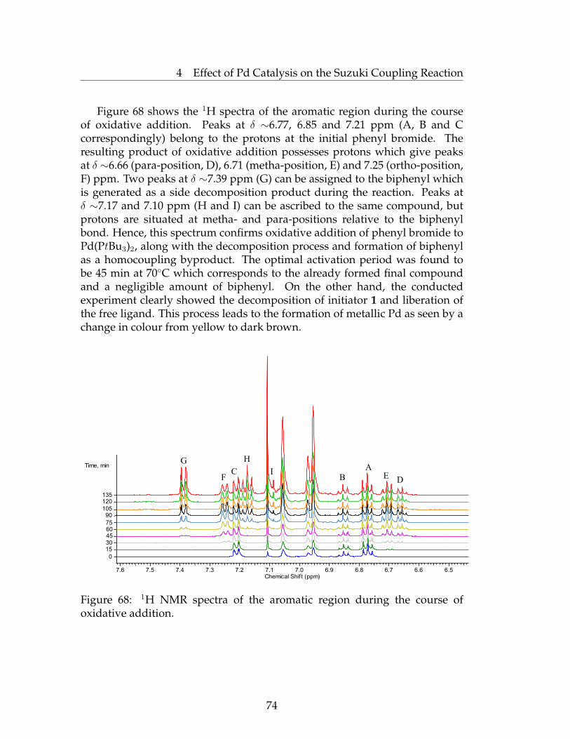
4 Effect of Pd Catalysis on the Suzuki Coupling Reaction
Figure 68 shows the 1H spectra of the aromatic region during the courseof oxidative addition. Peaks at δ ∼6.77, 6.85 and 7.21 ppm (A, B and Ccorrespondingly) belong to the protons at the initial phenyl bromide. Theresulting product of oxidative addition possesses protons which give peaksat δ ∼6.66 (para-position, D), 6.71 (metha-position, E) and 7.25 (ortho-position,F) ppm. Two peaks at δ ∼7.39 ppm (G) can be assigned to the biphenyl whichis generated as a side decomposition product during the reaction. Peaks atδ ∼7.17 and 7.10 ppm (H and I) can be ascribed to the same compound, butprotons are situated at metha- and para-positions relative to the biphenylbond. Hence, this spectrum confirms oxidative addition of phenyl bromide toPd(PtBu3)2, along with the decomposition process and formation of biphenylas a homocoupling byproduct. The optimal activation period was found tobe 45 min at 70◦C which corresponds to the already formed final compoundand a negligible amount of biphenyl. On the other hand, the conductedexperiment clearly showed the decomposition of initiator 1 and liberation ofthe free ligand. This process leads to the formation of metallic Pd as seen by achange in colour from yellow to dark brown.
NONAME03
7.6 7.5 7.4 7.3 7.2 7.1 7.0 6.9 6.8 6.7 6.6 6.5Chemical Shif t (ppm)
A
BC
DEF
G H
I
Time, min
120
105
90
75
60
60
45
30
15
0
Time, min
135120
10590
7560453015
0
Figure 68: 1H NMR spectra of the aromatic region during the course ofoxidative addition.
74

4 Effect of Pd Catalysis on the Suzuki Coupling Reaction
The 31P spectra also reveals significant changes during the first 90 min(Figure 69). It is clearly seen that consequent changes are minor and it is notnecessary to continue the activation process further.
140 130 120 110 100 90 80 70 60 50 40 30 20 10 0 -10Chemical Shif t (ppm)
Time, min
135
120
105
90
75
60
45
30
15
0
135
120
105
90
75
60
45
30
150
Figure 69: 31P NMR spectra during the course of oxidative addition.
4.2.2 XPS Study of the Oxidative Addition Stage
Additionally, an XPS study was performed to investigate the mechanismof the activation process. Thus, modified substrates were treated withPd(PtBu3)2, in toluene at 70◦C followed by washing of the excess catalyst. Inthe case of the initial 10 nm crosslinked PS(Br) film, the thickness increased byan additional ∼10 nm which was confirmed by ellipsometry. For the reactivesilane or PS(Br) monolayer of 1 nm thickness, this resulted in a 3 nm increase.Moreover, extensive rinsing of activated PS(Br) film resulted in much lessadditional PF thickness than in the case of an non-washed PS(Br) film afterthe activation stage.
75

4 Effect of Pd Catalysis on the Suzuki Coupling Reaction
XPS studies of a 10 nm crosslinked PS(Br) film (Figure 70) indeed displayeda high content of C and Br. The observed stoichiometric ratio [Br]/[C] wasequal to 0.094 which was less than the calculated value (0.125), mostly becauseof contamination of the surface with hydrocarbon compounds.
PS(Br) film PS(Br) film activated with Pd(PtBu3)2
[ N ]:[ C ]|spec - 0.032[ O ]:[ C ]|spec 0.008 0.44[ Na ]:[ C ]|spec - 0.001[ Si ]:[ C ]|spec 0.006 0.158[ P ]:[ C ]|spec - traces[ S ]:[ C ]|spec - 0.066[ Cl ]:[ C ]|spec - 0.007[ Zn ]:[ C ]|spec - >0.001[ Br ]:[ C ]|spec 0.094 0.004[ Pd ]:[ C ]|spec - 0.0084
Table 3: Elemental ratios determined by XPS of different atoms in a PS(Br) filmbefore and after activation with Pd(PtBu3)2.
A
B
Shake-up
C
O 1s
C 1s
800 600 400 200 0Binding energy [eV]
Si 2s
Br 3sBr 3p
340 335345
Pd 3d
300 85 758090
Br 3d
C 1sSi 2p
65 556070 50 45
Br 3d
Br 3d5/2Br 3d3/2
a)
D
300 290 280285295
Figure 70: XPS spectra of the crosslinked PS(Br) film.
The C 1s spectra corresponds to the expected C 1s spectra for poly(4-bromostyrene). Peak A shows the carbon atoms of the phenyl ring, Breveals saturated hydrocarbons whereas C corresponds to the carbon bond
76

4 Effect of Pd Catalysis on the Suzuki Coupling Reaction
to bromine. The intensity ratio [C]/[A] = 0.2 was in agreement with thestoichiometry of PS(Br). The elemental ratio [Br]/[C] determined from theC 1s spectra equialled the [Br]/[C] ratio, which was determined from thewide-scan spectra. Peak A is more intens than expected, mostly because ofcontamination of the surface with saturated hydrocarbon compounds. Anadditional small component peak D shows ether (C-O-C) and alcoholic (C-OH)groups resulting from the cross-linked PGMA, which was used as an adhesivelayer. Shake-up peaks of the C 1s spectra result from electron transitionbetween the π and π∗ orbitals of the phenyl rings.
Pd 3d
B
F E
O 1s C 1s
800 600 400 200 0Binding energy [eV]
Si 2s
S 2s
340 335345
Pd 3d
300 85 758090
C 1sSi 2p
65 556070 50 45
Br 3d
Br 3d5/2
Br 3d3/2
a)
D
Pd 3p1/2
Pd 3s N 1s
Pd 3d
S 2p
Pd 3sPd 3p
O 2s
Pd 4s Pd 4p3/2Pd 4p1/2
Pd 3d
3/2
5/2
F'
300 290 280285295
Figure 71: XPS spectra of the crosslinked PS(Br) film treated with Pd(PtBu3)2.
The reaction with Pd(PtBu3)2 lead to the high content of Pd in the polymerfilm (Figure 71). The [Pd]/[C] = 0.084 was close to the initial ratio [Br]/[C]of the non-treated PS(Br) film. Almost no bromine was found in the sampleafter the reaction with Pd(PtBu3)2 ([Br]/[C] = 0.004). That concludes thatmost of the bromophenyl groups were consumed during the reaction. Thecorresponding Pd 3d spectra shows only one Pd species. The binding energyof the Pd 3d5/2 peaks of 336.25 is slightly higher, as expected for the Pd metal.However, it perfectly agrees with PdO. Due to the high catalytic activity ofthe Pd NPs, the polymer layer was partly decomposed. The C 1s peak ispresented with a broad shoulder on its high-energy face, which is very atypicalfor the PtBu3 compound. The two component peaks D and E correspond tothe oxidized carbon species, such as alcoholic (C-OH) and keto groups (C=O).An additional peak F is probably due to carbonic acid groups (-COOH). The
77

4 Effect of Pd Catalysis on the Suzuki Coupling Reaction
carbon atom in the α-position to these carbonic acid groups (C-COOH) andC-N induced component peak F’. The most intense component peak B showssaturated hydrocarbons and carbon atoms of the residual phenyl rings. Noshake-up peaks were detected in the C 1s spectra due to the small number ofintact phenyl rings.
All the aforementioned data illustrate that treatment of PS(Br) withPd(PtBu3)2 lead to the near complete consumption of bromophenyl groups.Although XPS could not confirm the T-shaped monomer structure postulatedby Hartwig and co-workers, presumably in the form of Pd clusters were foundalone with a deep transformation of PS(Br). It could be proposed that theobserved complete decomposition was occurred during storage of the samplebefore the measurements due to the highly reactive and catalytic nature of Pdcomplexes. However, it cannot be excluded that freshly prepared samples alsocontains the molecular Pd complex which is unstable during storage.
4.3 Synthesis of Pd NPs and Utilization as a Catalyst inSuzuki Polycondensation
To verify whether Pd nanoparticles are indeed formed upon activation ofPS(Br) with Pd(PtBu3)2, the Pd-activated sample was investigated by AFM(Figure 72) and TEM (Figure 73). Both these measurements confirmed theformation of Pd nanoparticles of sizes ranging from 2 to 10 nm.
nm
μm
30
20
10
0.5 1.0 1.5 2.00
40
1.0µm
Figure 72: AFM topography image (left) and cross-section (right) of the 10 nmPS(Br) anchoring layer activated with Pd(0)-complex.
78
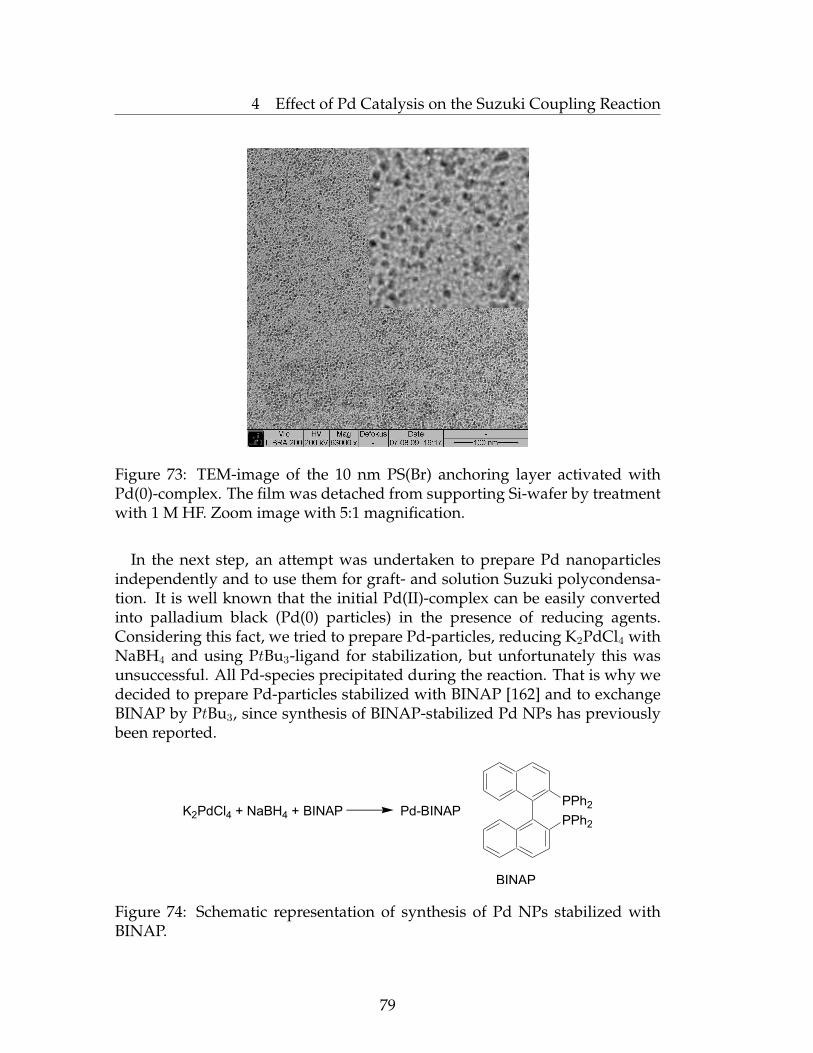
4 Effect of Pd Catalysis on the Suzuki Coupling Reaction
Figure 73: TEM-image of the 10 nm PS(Br) anchoring layer activated withPd(0)-complex. The film was detached from supporting Si-wafer by treatmentwith 1 M HF. Zoom image with 5:1 magnification.
In the next step, an attempt was undertaken to prepare Pd nanoparticlesindependently and to use them for graft- and solution Suzuki polycondensa-tion. It is well known that the initial Pd(II)-complex can be easily convertedinto palladium black (Pd(0) particles) in the presence of reducing agents.Considering this fact, we tried to prepare Pd-particles, reducing K2PdCl4 withNaBH4 and using PtBu3-ligand for stabilization, but unfortunately this wasunsuccessful. All Pd-species precipitated during the reaction. That is why wedecided to prepare Pd-particles stabilized with BINAP [162] and to exchangeBINAP by PtBu3, since synthesis of BINAP-stabilized Pd NPs has previouslybeen reported.
K2PdCl4 + NaBH4 + BINAP Pd-BINAP
BINAP
PPh2
PPh2
Figure 74: Schematic representation of synthesis of Pd NPs stabilized withBINAP.
79

4 Effect of Pd Catalysis on the Suzuki Coupling Reaction
The size of the obtained BINAP-stabilized Pd-particles, about 1-10 nm,was proven by TEM investigations (Figure 75). DLS measurments alsoconfirmed this value. Bulk-polymerizations of the monomer (7-bromo-9,9-bis(2-ethylhexyl)-9H-fluoren-2-yl-boronic acid ester) initiated by Pd-BINAPNPs using Na2CO3 base did not lead to any significant monomer conversioneven after 100 hours of reflux. The same situation was observed in case whenthe PtBu3 ligand was added to BINAP-stabilized Pd-particles.
Figure 75: TEM-image of Pd-BINAP nanoparticles deposited onto a PS(Br)film. The film was detached from supporting Si-wafer by treatment with1 M HF. Zoom image with 4:1 magnification.
Despite of the bulk solution polymerization using BINAP-stabilized PdNPs, graft-polymerization was also attempted. To this end, activation ofsurface-immobilized PS(Br) films was performed by BINAP-stabilized Pd-nanoparticles. The TEM image of thus activated and floated PS(Br) filmrevealed successful immobilization of Pd NPs (Figure 75). Pd NPs are partiallyagglomerated to give a dots with the size about 10-15 nm.
Afterwards, grafting of PF2/6 brushes from PS(Br) thin films developed onSi-wafers and activated with BINAP-stabilized as well as PtBu3-stabilized PdNPs was attempted. For the immobilization of Pd NPs, a 10 nm thin PS(Br)film developed on a Si-wafers was dipped into Pd-PtBu3 NPs dispersioneither at r.t. or at 70◦C and graft-polymerization was attempted afterwardsby placing the activated wafers into monomer solution under an argonatmosphere.
80
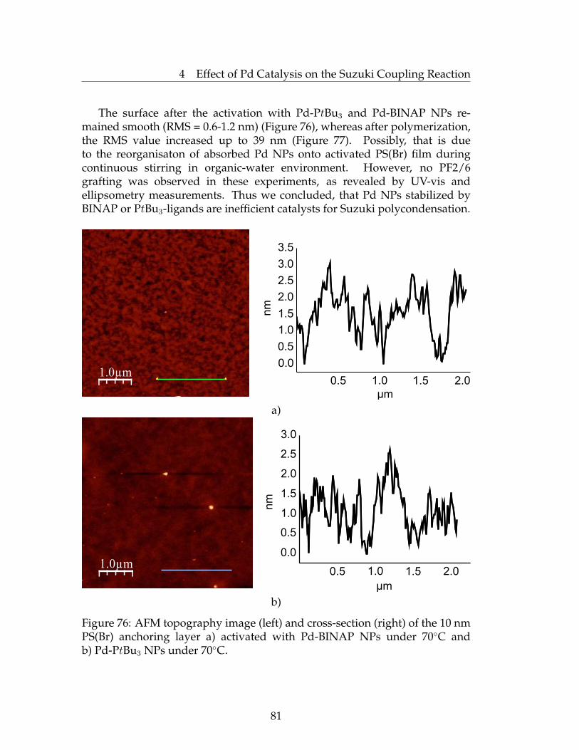
4 Effect of Pd Catalysis on the Suzuki Coupling Reaction
The surface after the activation with Pd-PtBu3 and Pd-BINAP NPs re-mained smooth (RMS = 0.6-1.2 nm) (Figure 76), whereas after polymerization,the RMS value increased up to 39 nm (Figure 77). Possibly, that is dueto the reorganisaton of absorbed Pd NPs onto activated PS(Br) film duringcontinuous stirring in organic-water environment. However, no PF2/6grafting was observed in these experiments, as revealed by UV-vis andellipsometry measurements. Thus we concluded, that Pd NPs stabilized byBINAP or PtBu3-ligands are inefficient catalysts for Suzuki polycondensation.
1.0µm
μm
nm
0.0
0.5
1.0
1.5
2.0
2.5
3.0
3.5
0.5 1.0 1.5 2.0
a)
1.0µm1.0µm
μm
nm
0.0
0.5
1.0
1.5
2.0
2.5
3.0
0.5 1.0 1.5 2.0
b)
Figure 76: AFM topography image (left) and cross-section (right) of the 10 nmPS(Br) anchoring layer a) activated with Pd-BINAP NPs under 70◦C andb) Pd-PtBu3 NPs under 70◦C.
81
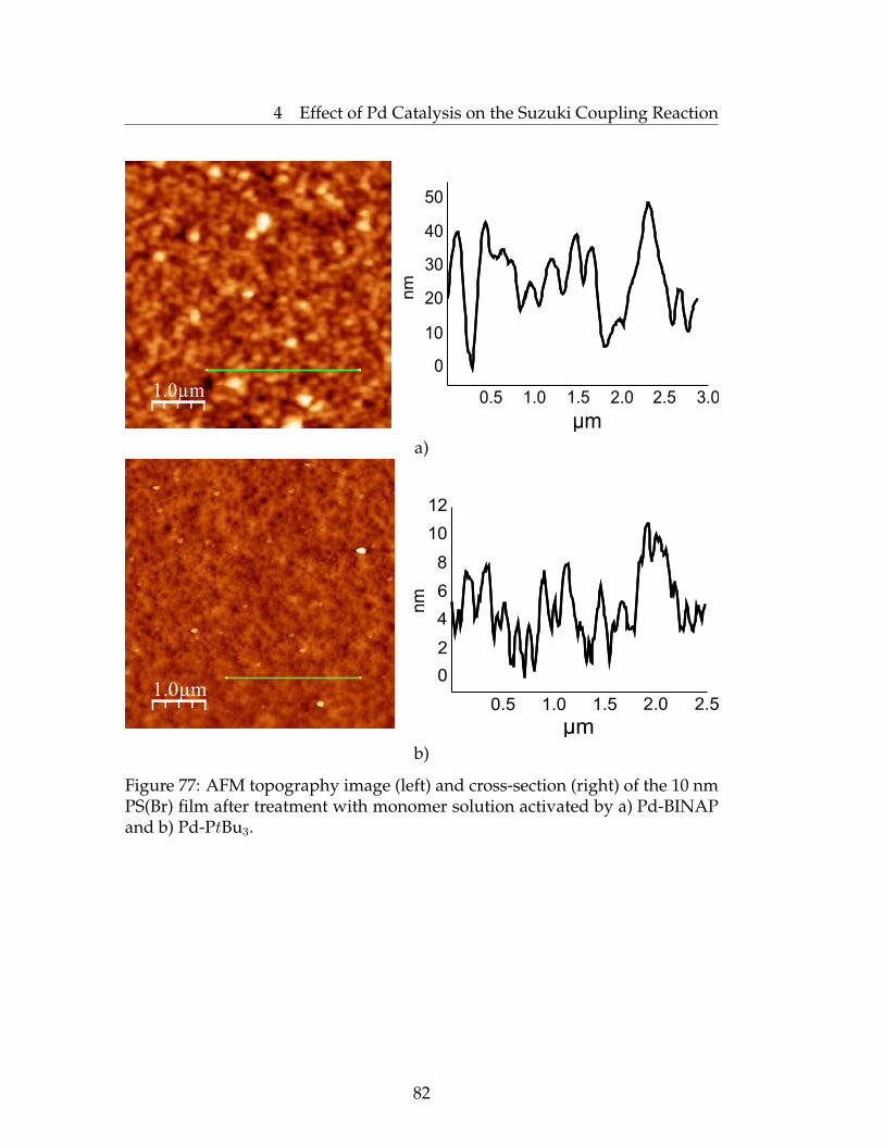
4 Effect of Pd Catalysis on the Suzuki Coupling Reaction
1.0µmnm
μm
0
10
20
30
40
50
0.5 1.0 1.5 2.0 2.5 3.0
a)
1.0µm
μm
nm
0.5 1.0 1.5 2.0 2.5
0
2
4
6
8
10
12
b)
Figure 77: AFM topography image (left) and cross-section (right) of the 10 nmPS(Br) film after treatment with monomer solution activated by a) Pd-BINAPand b) Pd-PtBu3.
82
4 Effect of Pd Catalysis on the Suzuki Coupling Reaction
4.4 Conclusions
NMR, XPS, AFM and TEM studies were performed to understand theprocess of preparation of PF2/6 brushes and to optimize grafting conditions.
31P NMR studies of the process of preparation of Pd-based initiators forSuzuki polycondensation allowed us to determine the optimal conditionsfor activation of the initiator precursor. Investigations also revealed that Pdnanoparticles were indeed formed during activation of the PS(Br) anchoringlayer; however, we did not obtain any proof that these NPs play a catalyticrole in the grafting-from process. If so, the question of what factor isresponsible for the remarkable "stickiness" of the Pd catalyst species to thesurface is still open. An alternative explanation would be that the highhydrophobicity of Pd catalyst species supported by PtBu3 ligands and the highpolarity of the water-saturated solution forces Pd catalysts to segregate into ahighly hydrophobic anchoring layer and further, during the polymerization,into a PF2/6 brush film. In this case, escaping of the Pd species into awater-saturated environment to induce polymerization in bulk solution is athermodynamically unfavourable process. However, more investigations arenecessary to prove this hypothesis.
4.5 Experimental Part
Materials. 2,2’-bis-(diphenylphosphino)-1,1’-binaphthyl (BINAP), sodiumborohydride (NaBH4), potassium tetrachloropalladate (K2PdCl4), tetraocty-lammonium bromide N(C8H17)4Br, dichloromethane, acetone, chloroform,hexane, toluene, PtBu3, hydrofluoric acid (HF), tetrahydrofuran (THF,stabilizer free, anhydrous) were purchased from Aldrich and used asreceived without further purification. Poly(glycidyl methacrylate), PGMA(Mn=65 000 g/mol, PDI=2.05) was purchased from Polymer Source Inc.Poly(4-bromostyrene) (Mn=51 000 g/mol, PDI=2.05) was obtained via radicalpolymerization of 4-bromostyrene [108]. 7-Bromo-9,9-bis(2ethylhexyl)-9H-fluoren-2-ylboric acid ester [109], BINAP-Pd NPs were prepared as previouslydescribed.
Preparation of PS(Br) film with immobilized Pd NPs for TEM-investigations.Si-wafer with spin-coated PS(Br) and deposited Pd NPs was partially pulleddown into the 1M HF and was retained for 1 hour to detach the film fromsupporting Si-wafer. Detached film was carefully collected by flotation anddeposited onto TEM grid.
83

4 Effect of Pd Catalysis on the Suzuki Coupling Reaction
Activation of PS(Br) film with Pd(PtBu3)2 or Pd-BINAP NPs and grafting ofPF2/6 was performed as described in previous Chapter 3. Concentration ofsynthesized Pd-BINAP NPs utilized in activation process was 3 mg/ml. Toperform the ligand-exchange ten-fold excess of PtBu3-ligand was added to thePd-BINAP NPs solution and heated for 30 min at 70◦C.
Polymerization of PF2/6 in bulk initiated by Pd NPs. 7-Bromo-9,9-bis(2ethylhexyl)-9H-fluoren-2-ylboric acid ester (300 mg, 0.504 mmol) wasplaced in a round-bottomed flask equipped with a magnet stirrer bar, andthe atmosphere was replaced with argon. Dry THF (7 ml) and 2M aqueoussodium carbonate (0.3 ml) were added via a syringe. In glovebox Pd-BINAPNPs (2.5 mg, 0.0034 mmol) and PtBu3 (6.9 mg, 0.034 mmol) were placed intoa round-bottomed flask and then the mixture was stirred for 30 min at 70◦C.Simultaneously Pd-BINAP NPs (2.5 mg, 0.0034 mmol) were dissolved in THFin another round-bottomed flask. Mixture of monomer and aqueous sodiumcarbonate was equally added to each Pd-containing flask and allowed to reactunder reflux for several days. The reaction mixture was quenched by 2Mhydrochloric acid and the products were extracted with CHCl3. The organiclayer was washed with water, dried over anhydrous MgSO4 and concentratedunder reduced pressure. NMR-investigations detected pure monomer withoutany conversion.
84

5 Grafting of PFO by Kumada Method
5 Grafting of PFO by Kumada Method
5.1 Poly(9,9-dioctyl fluorene) (PFO) Brushes Grafted fromPS(Br)-latex Nanoparticles
It is well established that thin-film optoelectronic device propertiessuch as emission color and quantum efficiency are strongly dependenton the organization of the polymer molecules and their interactions withother constituents in multicomponent devices. In general, self-assemblyis a powerful and cost-efficient approach in the fabrication of complexnanostructured materials. Possibly, the use of nanoscale, three-dimensional,shape-persistent and covalently preorganized building blocks may enable self-assembly of complex multicomponent functional structures with a higherdegree of control. Nanoparticles in which conjugated polymer chains areattached to a particle core by one end and stretched away from the core to formspherical brushes are likely to be the required blocks. In addition, conjugatedchains densely grafted to microspheres might lead to the improvement ofintermolecular charge transport.
The aforementioned "grafting to" approach usually provides rather lowgrafting densities, whereas "grafting from" avoids this limitation. Barnesand co-workers tried to attach oligophenylene vinylene to properly modifiedquantum dots [78]. Following this idea, Schanze et al. grafted polyacetylenefrom silica microspheres, but the obtained brush thickness was only up to12 nm [79]. Recently, Kiriy and co-workers developed a new elegant methodto grow P3HT brushes from nanoscale silica nanoparticles [163]. The obtained"hairy" nanoparticles possess a high grafting density which corresponds to a"true brush" regime. A PV device based on these particles showed reasonablygood performance.
Being interested in optoelectronic devices based on polyfluorenes we triedto apply the "grafting from" approach to grow poly(9,9-dioctyl fluorene) (PFO)brushes from PS(Br) latex nanoparticles (Figure 78).
[Ni-catal] grafting of PFO
Figure 78: Schematic representation of grafting of PFO from PS(Br) latexnanoparticles.
85
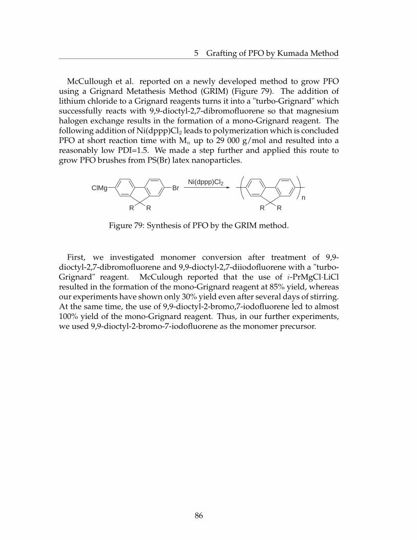
5 Grafting of PFO by Kumada Method
McCullough et al. reported on a newly developed method to grow PFOusing a Grignard Metathesis Method (GRIM) (Figure 79). The addition oflithium chloride to a Grignard reagents turns it into a "turbo-Grignard" whichsuccessfully reacts with 9,9-dioctyl-2,7-dibromofluorene so that magnesiumhalogen exchange results in the formation of a mono-Grignard reagent. Thefollowing addition of Ni(dppp)Cl2 leads to polymerization which is concludedPFO at short reaction time with Mn up to 29 000 g/mol and resulted into areasonably low PDI=1.5. We made a step further and applied this route togrow PFO brushes from PS(Br) latex nanoparticles.
ClMg Br
R R R R
Ni(dppp)Cl2
n
Figure 79: Synthesis of PFO by the GRIM method.
First, we investigated monomer conversion after treatment of 9,9-dioctyl-2,7-dibromofluorene and 9,9-dioctyl-2,7-diiodofluorene with a "turbo-Grignard" reagent. McCulough reported that the use of i-PrMgCl·LiClresulted in the formation of the mono-Grignard reagent at 85% yield, whereasour experiments have shown only 30% yield even after several days of stirring.At the same time, the use of 9,9-dioctyl-2-bromo,7-iodofluorene led to almost100% yield of the mono-Grignard reagent. Thus, in our further experiments,we used 9,9-dioctyl-2-bromo-7-iodofluorene as the monomer precursor.
86

5 Grafting of PFO by Kumada Method
PS(Br) particles, ∼35 nm in diameter, were prepared by miniemulsionradical copolymerization of styrene bromide with 5% of crosslinker (di-vinylbenzene). Grafting of PFO was attempted using a recently developedprocedure [164]. The prepared particles with a PS(Br) core and a PFO shellwere extensively characterized. SEM measurements revealed that SIP inducedan increase in particles size up to 40 nm in diameter (Figure 80).
a)
b)
Figure 80: SEM image of a) PS(Br) latex nanoparticles, b) PFO grafted fromPS(Br) latex nanoparticles.
87

5 Grafting of PFO by Kumada Method
Homogeneous layers of PS(Br)-PFO NPs could be prepared by spin-coatingthe dispersion onto silica or other substrates. The resulting films consistedof a 90 nm thick layer of closely packed particles, as seen by AFM; themicrographs did not reveal any cracks within an area of 2x2 µm2 (Figure 81, a).It is worth noting that spin-coated linear PFO illustrates self-assemblinglamellar structures due to the relatively long symmetrical substituents atthe 9th position which induces formation of the β-phase (a highly orderedconformation of planarized chains) (Figure 81, b).
400nm
nm
nm
200 400 600 800
0
4
8
12
16
a)
200nm
b)
Figure 81: AFM topography image and cross-sections of the a) 90 nm PS(Br)-core PFO-shell nanoparticles and b) AFM phase image of linear PFO.
88
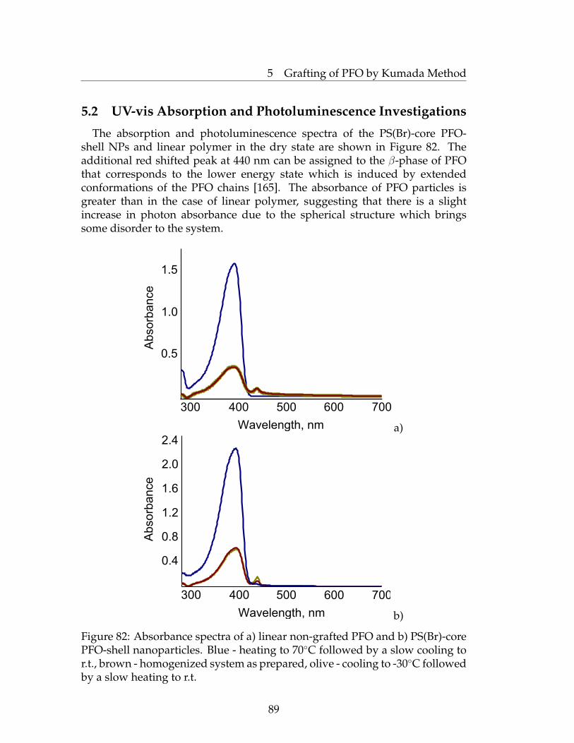
5 Grafting of PFO by Kumada Method
5.2 UV-vis Absorption and Photoluminescence Investigations
The absorption and photoluminescence spectra of the PS(Br)-core PFO-shell NPs and linear polymer in the dry state are shown in Figure 82. Theadditional red shifted peak at 440 nm can be assigned to the β-phase of PFOthat corresponds to the lower energy state which is induced by extendedconformations of the PFO chains [165]. The absorbance of PFO particles isgreater than in the case of linear polymer, suggesting that there is a slightincrease in photon absorbance due to the spherical structure which bringssome disorder to the system.
Wavelength, nm
Ab
so
rba
nce
0.5
1.0
1.5
300 400 500 600 700
a)
Abso
rba
nce
Wavelength, nm
300 400 500 600 700
0.4
0.8
1.2
1.6
2.0
2.4
b)
Figure 82: Absorbance spectra of a) linear non-grafted PFO and b) PS(Br)-corePFO-shell nanoparticles. Blue - heating to 70◦C followed by a slow cooling tor.t., brown - homogenized system as prepared, olive - cooling to -30◦C followedby a slow heating to r.t.
89
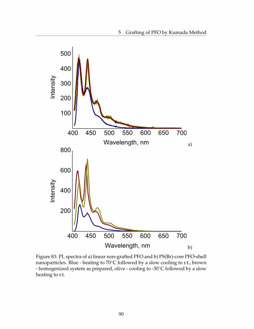
5 Grafting of PFO by Kumada Method
Wavelength, nm
Inte
nsity
100
200
300
400
500
400 450 500 550 600 650 700
a)
Inte
nsity
Wavelength, nm
200
400
600
800
400 450 500 550 600 650 700
b)
Figure 83: PL spectra of a) linear non-grafted PFO and b) PS(Br)-core PFO-shellnanoparticles. Blue - heating to 70◦C followed by a slow cooling to r.t., brown- homogenized system as prepared, olive - cooling to -30◦C followed by a slowheating to r.t.
90
5 Grafting of PFO by Kumada Method
β-phase emission is characterized by well-defined sharp vibronic featureswith almost no Stokes shift. The enlargement of the β-phase emission comesthrough efficient Forster energy transfer from the "host" amorphous α- phasePFO to the "guest" β-phase inclusions in the PFO matrix. Such materialscan be viewed as self-doped polymer systems. Figure 83 illustrates the PLspectra of PS(Br)-core PFO-shell nanoparticles and non-grafted linear PFO.Thus, the increased absorbance and photoluminescence intensity of PFOnanoparticles, comparably with linear non-grafted polymer, can be assigned tothe better structural packing and, as a consequence, improved charge transportproperties. We also compared the absorbance and PL spectra of spin-coatedfilms of PFO particles homogenized at room temperature and linear PFO.Both were driven into a crystalline phase by heating to 70◦C followed by aslow cooling to room temperature or in the opposite direction, namely coolingto -30◦C followed by slow heating to room temperature. We found that thehighest emission intensity of peak corresponding to the β-phase was observedfor the sample which was slowly heated from -30◦C to room temperature.Such an increase in PL intensity is expected from the suggestion regardinga mechanism of crystalline phase formation. During heating, the partiallyordered system converts into disordered one, and then as long as it is cooleddown, polymer chains tend to pack efficiently in order to reach the minimumenergy, but in some sense it is still a more or less disordered state. In theopposite direction, during cooling, the system is quenched, thus the volumeof initial glassy (α) and β-phase are preserved. For the time being reversiblyslowly heated to room temperature, polymer chains tend to take up favorablepacking which leads to an increased β-phase content and, as a consequence,increased emission intensity in some cases.
Prior to use in the device, the PFO nanoparticles were purified properlyfrom the residual Ni-catalyst which can be bound to conjugated polymers. Theremaining Ni could not be completely removed using the usual purificationtechniques. Moreover, the metal contamination (0.0001-1%) often goesundetected due to the concentration limits of common analytical techniques(elemental analysis, NMR, etc.). The presence of residual metal couldbe the cause of short circuits and lead to poor electrical performance ofelectroactive devices [166, 167]. We treated the solution of PFO particles withi-PrMgCl at 70◦C for 3 hours to react with the residual Ni. Consequently,ethylenediaminetetraacetic acid sodium salt was allowed to stir with thecollected substance. The resulting product was extracted, dried and usedwithout further purification.
91
5 Grafting of PFO by Kumada Method
5.3 Conclusions
Grafting of PFO from PS(Br) latex nanoparticles using surface-initiatedKumada polycondensation was successfully performed. The obtainedparticles possessed typical PFO structural features which, as a result ofβ-phase formation, caused additional peak in the absorbance and PL spectra.The largest increment of the β-phase was observed during slow heating ofquenched material from -30◦C to room temperature. Thus, these particlesmight be a challenging material for optoelectronic devices capable of efficientpolarized emission. The properties of the emitting layer might be improvedby mixing with appropriate dopant along with replacement of insulatingPS(Br)-core into magnetic, conducting or other substances.
5.4 Experimental Part
Materials. 4-Bromostyrene, aluminum oxide (activated, basic, Brockmann I),Ni(dppp)Cl2, ethylenebis(diphenylphosphine) (dppe), 9,9-dioctyl-2,7-dibro-mofluorene, 9,9-dioctyl-2-bromo-7-iodofluorene, i-PrMgCl·LiCl, bromoben-zene, divinylbenzene, sodium dodecyl sulfate, potassium persulfate, methanol,chloroform, dichloromethane, acetone, hydrochloric acid, and tetrahydrofuran(THF, stabilizer free, anhydrous) were purchased from Aldrich and used asreceived without further purification.
Preparation of 9,9-dioctyl-2-chloromagnezium-7-bromofluorene (1a). Around bottomed flask equipped with septum was several times heated underreduced pressure then cooled to room temperature under argon atmosphere.9,9-dioctyl-2,7-dibromofluorene (1.6465 g, 3 mmol) was placed in the flask.Dry THF (10 ml) was added to the flask via a syringe, and the mixture wasstirred at 0◦C. i-PrMgCl·LiCl (1.3 M solution in THF, 2.31 ml, 3 mmol) wasadded via syringe, and the mixture was slowly heated to room temperatureand stirred for 3 days.
Alternative route of preparation of 9,9-dioctyl-2-chloromagnezium-7-bro-mofluorene from 9,9-dioctyl-2-iodo-7-bromofluorene (1.7868 g, 3 mmol) hasbeen the same as shown before.
92

5 Grafting of PFO by Kumada Method
Preparation of PS(Br)-latex NPs. 4-bromostyrene (3.3 g, 18 mmol) anddivinylbenzene (0.66 g, 5 mmol) were purified under aluminum oxide prior touse and placed with sodium dodecyl sulfate (600 mg) into a round bottomedflask equipped with septum. Then solution of potassium persulfate (10 mg)in 60 ml of degassed water was added. The mixture was stirred under 70◦Covernight. The resulting product was filtrated, washed several times withmixture of methanol and water then only water and dried in vacuum under60◦C. Yield: 3.68 g.
Preparation of PS(Br)-core PFO-shell NPs. PS(Br) NPs (150 mg) weredispersed in dry THF (35 ml) in a round bottomed flack equipped with septumunder inert atmosphere. Et2NiBiPy (11.475 mg, 0.042 mmol) was dissolved indry THF (10 ml) and allowed to stir with PS(Br) NPs solution for 1 hour. Dppe(18.41 mg, 0.0462 mmol) was dissolved in 5 ml dry THF, added to the reactionmixture and allowed to stir for 2 hours. Prior to polymerization, thus-treatedparticles were purified from unreacted dppe by repeated redispersion (indichloromethane)/centrifugation cycles. Grafting of PFO was attempted bythe addition of 9,9-dioctyl-2-chloromagnezium-7-bromofluorene (3 mmol) inTHF (50 ml) followed by stirring under 0◦C for 30 min. After quenching of thepolymerization mixture with 3M EtMgBr and HCl/MeOH, the particles werecarefully purified by redispersion in hot chloroform and filtration throughsilica gel. By following extraction in the Sokslet apparatus in methanol,hexane, dichloromethane and chloroform resulting PS(Br)-PFO NPs werepurified from unreacted monomer and linear nongrafted PFO. Yield: 943.2 mg,81%.
93

6 Organic Light-Emitting Diodes
6 Organic Light-Emitting Diodes
6.1 Introduction to Organic Light-Emitting Diodes (OLEDs)
Light-emitting diodes (LEDs), or electroluminescent devices, based onorganic materials have been the subject of a number of recent publications.Polymer light-emitting diodes (PLED)-based displays are attractive due totheir processing advantages in device manufacturing. The organic materials,used as the emitting layers, are readily soluble in common organic solvents orin water. Uniform and pinhole-free thin films can be steadily cast from solutionat room temperature through spin-coating or other techniques. Because of thepolymeric nature, they are flexible and can be easily fabricated onto rigid orflexible substrates with different shapes. The colour of the emission dependsupon the size of the HOMO-LUMO energy gap. For visible light (380-780 nm),this corresponds to 1.5-3.2 eV. Another advantage of organic semiconductorsis that the energy band gap of a given system can be tuned via chemicalmodification of the polymer structure.
In a full-colour display, each colour pixel contains three subpixels withprimary colours in the red, green and blue emission zones, respectively. Apopular approach for fabricating such colour pixels is fabricating each coloursubpixel with EL materials in the corresponding emission spectra. Currently,PLEDs emitting light in the red and green regions are industrially available.They display pure colour with height efficiency and brightness; howeverthey suffer from thermal destruction during long-time operation process.Nevertheless, efficient and stable saturated blue emission is required and, thusfar, remains the main challenge.
The first report of blue emission from a conjugated polymer LED wasfor poly(p-phenylene) [102]. Poly(alkylfluorene) derivatives are among themost promising blue-emitting materials for PLEDs because of their excellentoptical and electronic properties as well as their high thermal and chemicalstability. PFs demonstrate a strong blue fluorescence emission, arising froma highly conjugated planar π-electron system. In fact, PFs are the onlyclass of conjugated polymers that can emit a whole range of visible colourswith relatively high quantum efficiency (QE). Moreover, the liquid crystallineorder of some PFs has opened the way to the fabrication of blue polarizedelectroluminescent devices.
This chapter gives a brief review of the PLEDs, their main characteristicsand our results in the fabrication and characterization of PLEDs using PFObrush nanoparticles, synthesis of which was presented in the previous chapter.
94

6 Organic Light-Emitting Diodes
6.2 The Basics of OLEDs
The PLED is typically prepared with a thin layer of semiconducting polymerfilm sandwiched between two electrodes. A simple schematic picture of theelectroluminescence process is depicted in Figure 84. Electrones are injectedfrom the cathode, holes are injected from the anode (1 - charge injection). Theseelectrons and holes generate negative and positive polarons, respectively.After that, carriers migrate along the polymer chain toward the oppositeelectrode under the influence of the applied electric field (2 - charge transport)and combine in a segment of the polymer chain to form singlet excitons (3 -exciton formation) as produced by photoexcitation in PL. The singlet excitonsdecay to the ground state by emission of a photon with an energy determinedby the polymer composition (4 - radiative exciton recombination, 5 - lightemission).
Transparent
anode
reflective
cathodeHTL ETL
12
3
4
1 2
5
Figure 84: General operation principle of an OLED.
The process of electron-hole capture is crucial to device operation. Onlysinglet excited states can induce fluorescence emission. High emission requiresthat S1, the lowest singlet excited state, be strongly coupled with the groundstate S0 and possesses symmetry opposite to it. Oppositely, triplet excitedstates do not decay radiatively. Spin statistics states, that the maximuminternal quantum efficiency for electroluminescence (EL) cannot exceed 25%of the PL efficiency, since the ratio of triplets to singlets is 3:1. Nevertheless,the triplet excited state induces phosphorescence emission, which has its owndrawbacks and benefits.
In order to achieve efficient luminescence, several problems must beovercome. First of all, the polymer layer must be homogeneous and without
95

6 Organic Light-Emitting Diodes
any impurities, which can cause charge-trapping with following emissionin an undesirable wavelength region, or can lead to nonradiative processes.The latter especially unwanted, because it can cause thermal degradation inthe system. The nature of the interfaces between the active light-emittingpolymer layer and the ITO (indium-tin oxide) or metal electrode is ofparamount importance. The control of these layers may lead to the significantimprovement of device performance.
Along with this, the charge balance is strictly required. During deviceoperation, unbalanced carrier mobility means the number of electrons andholes at the emission zone is different, which leads to low current efficiencyin device performance. Moreover, the recombination zone can be shifted tothe interface that also causes undesired emissions.
The ITO substrate is the most commonly used anode for the fabricationof OLEDs. This is a non-stoichiometric mixture of In, In2O, InO, In2O3,Sn, SnO and Sn2O3. Due to its transparency, light generated within thediode is able to leave the device. The value of ITO work-function istypically ∼4.7 eV, but can be gently tuned via plasma oxygen treatment up toapprox. 5.1 eV. To displace the rigid anode material with a flexible one, severaldoped conducting polymers have been tried as a native anode layer. Forinstance, OLEDs employing a polyaniline-poly(styrene sulfonate) (PANI-PSS)blend have shown increased brightness and lifetime, compared to ITO [168].Yang et al. also tried polypyrrole as an anode [169, 170]. A considerablerestriction of these materials is the complexity of device manufacturing. Onesplendid solution is the utilization of a poly(3,4-ethylenedioxythiophene)poly(styrenesulfonate) (PSS-PEDOT) blend [171, 172, 173, 174, 175].
As mentioned above, PSS-PEDOT can be used as a transparent anode.However, it is now commonly deposited on ITO as an HTL (hole-transportlayer). This is a complex of two charged polymers, which possess lowresistivity and heigh transmittance. This layer prevents direct contact betweenthe anode and the upper organic layer. The indicated role is very importantbecause it avoids a fast degradation of the devices due to the large numberof short-circuits between the two materials. The second purpose of PSS-PEDOT is to enhance the injection of holes from the anode into the organiclayers, thus reducing the height of the energetical barrier at the ITO-organicinterface. In addition to optimizing hole injection, this buffer layer also servesas a planarization layer to eliminate pin-holes in the EL layer caused by therough ITO surface. It also serves as a chemical buffer, preventing chemicalimpurities in the substrate and the transparent ITO electrode from reachingEL polymers, therefore significantly improving PLED operation time [176]. Inthe near future, elegant flexible electronic devices will be produced utilizingPSS-PEDOT as a native anode layer. Other typical hole-transport layers areillustrated at Figure 85.
96
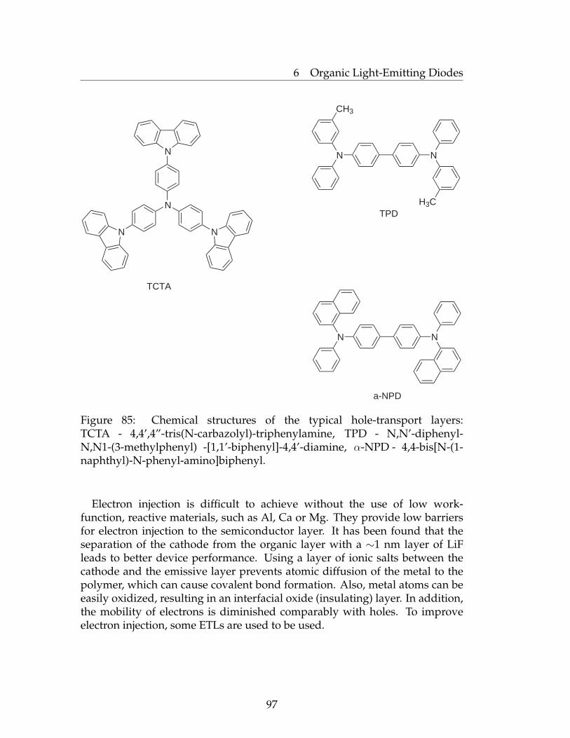
6 Organic Light-Emitting Diodes
N
NN
N
TCTA
N N
CH3
H3C
N N
TPD
a-NPD
Figure 85: Chemical structures of the typical hole-transport layers:TCTA - 4,4’,4”-tris(N-carbazolyl)-triphenylamine, TPD - N,N’-diphenyl-N,N1-(3-methylphenyl) -[1,1’-biphenyl]-4,4’-diamine, α-NPD - 4,4-bis[N-(1-naphthyl)-N-phenyl-amino]biphenyl.
Electron injection is difficult to achieve without the use of low work-function, reactive materials, such as Al, Ca or Mg. They provide low barriersfor electron injection to the semiconductor layer. It has been found that theseparation of the cathode from the organic layer with a ∼1 nm layer of LiFleads to better device performance. Using a layer of ionic salts between thecathode and the emissive layer prevents atomic diffusion of the metal to thepolymer, which can cause covalent bond formation. Also, metal atoms can beeasily oxidized, resulting in an interfacial oxide (insulating) layer. In addition,the mobility of electrons is diminished comparably with holes. To improveelectron injection, some ETLs are used to be used.
97
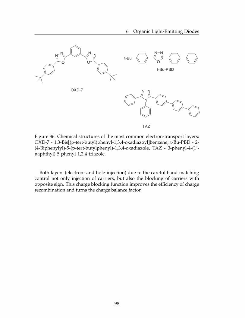
6 Organic Light-Emitting Diodes
NN
O O
NN
OXD-7
t-BuO
NN
t-Bu-PBD
NN
N
TAZ
Figure 86: Chemical structures of the most common electron-transport layers:OXD-7 - 1,3-Bis[(p-tert-butyl)phenyl-1,3,4-oxadiazoyl]benzene, t-Bu-PBD - 2-(4-Biphenylyl)-5-(p-tert-butylphenyl)-1,3,4-oxadiazole, TAZ - 3-phenyl-4-(1’-naphthyl)-5-phenyl-1,2,4-triazole.
Both layers (electron- and hole-injection) due to the careful band matchingcontrol not only injection of carriers, but also the blocking of carriers withopposite sign. This charge blocking function improves the efficiency of chargerecombination and turns the charge balance factor.
98

6 Organic Light-Emitting Diodes
6.3 Characterization of OLEDs
The criteria for evaluating the performance of an OLED include luminance,efficiency (commonly current efficiency, power efficiency, or external quantumefficiency), turn-on voltage, lifetime and current-density voltage relation.
The current-voltage characteristic is a relationship between currentdensity and the corresponding voltage. A schematic representation of theprocess is shown in Figure 87. In unbiased (no applied external voltage)conditions, electrons from the n-type side diffuse over to the p-type side wherethey recombine with holes. A corresponding process occurs with holes thatdiffuse to the n-type side. This region is known as the depletion region. Uponapplication of the forward bias voltage, electrons and holes are injected andcurrent flow increases. The carriers diffuse into the regions with the oppositeconductivity type where they recombine and emit a photon.
Figure 87: Schematic representation of a) forward biased pn-junction, b)reverse biased pn-junction.
99
6 Organic Light-Emitting Diodes
Internal quantum efficiency is defined as the ratio of the number of photonsproduced within the device to the number of electrons injected into the LED(Equation (13)).
ηint = γrstq (13)
rst is the fraction of excitons in a singlet state, q is the efficiency of radiativedecay of these singlet excitons. γ is the charge balance factor, which can bedefined as the ratio of the electron-hole recombination current density, J , andthe measured current density Jr (Equation (14)).
γ =JγJ
(14)
The external quantum efficiency ηext is defined as the ratio of the numberof emitted photons outside a device divided by the number of charges injectedinto a device. As discussed before, the efficiency of radiative decay dependson the device structure.
Turn-on voltage is defined as the voltage corresponding to a luminance of1 cd/m2.
Luminance is a luminous intensity per unit area projected in a givendirection. The SI unit is the candela per square meter (cd/m2), which is stillsometimes called a nit. The footlambert (fL) is also in common use, with1 fL=3.426 cd/m2.
The operating lifetime is defined as the time for the light emission to decayto half of its initial value under continuous, constant current operation.
Additionally, in the application of light emission, the carrier mobilityof the polymer plays an important role. Depending on the detailedmolecular structures, the morphology and the electric field strength applied,carrier mobility in typical organic semiconductors is in the range of 10−7 to10−2 cm2/(V·s).
100

6 Organic Light-Emitting Diodes
6.4 Device Preparation
We assumed that the particles with a modificated PFO brush surface woulddisplay improved device performance and charge mobility compared to thespin-coated film of the same linear polymer.
Two sets of PLEDs were fabricated on indium tin oxide (ITO) coated glasssubstrates, as can be seen in Figure 88. The thickness of ITO layer was∼100 nm.
Al
BPhen:Cs
BPhen
PFO NPs
PSS-PEDOT
ITO
Glass
Al
BPhen:Cs
BPhen
linear PFO
PSS-PEDOT
ITO
Glass
Figure 88: Two types of OLED devices.
First, the PSS-PEDOT hole-transport layer was directly spin-coated on topof ITO in order to improve hole-injection and substrate smoothness and toenhance the performance of the PLEDs. Afterwards, the sample was annealedat 150◦C. The annealing lead to further smoothening of the surface (Figure 89)and to improved electron transport as confirmed by measurements of lateralconductivities (from 0.001 Scm−1 to 0.04 Scm−1). The obtained thickness was30 nm. Afterwards, a layer of PS(Br)-core PFO-shell nanoparticles with athickness of 90 nm was spin-coated. The second type of OLED consisted ofthe same layers as previously described, but linear PFO of the same 90 nmthickness was used instead of the PS(Br)-core PFO-shell nanoparticles.
101
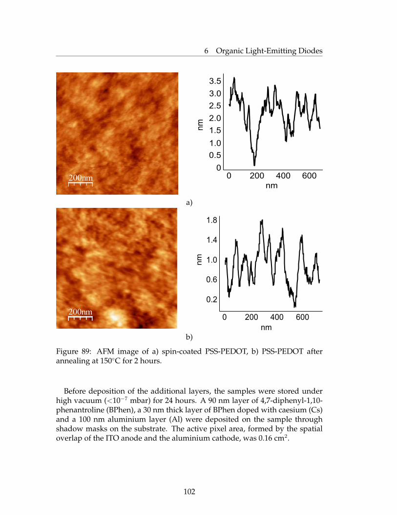
6 Organic Light-Emitting Diodes
200nm
nm
nm
0
0
200 400 600
0.5
1.0
1.5
2.0
2.5
3.0
3.5
a)
200nm
nm
nm
0.2
0.6
1.0
1.4
1.8
0 200 400 600
b)
Figure 89: AFM image of a) spin-coated PSS-PEDOT, b) PSS-PEDOT afterannealing at 150◦C for 2 hours.
Before deposition of the additional layers, the samples were stored underhigh vacuum (<10−7 mbar) for 24 hours. A 90 nm layer of 4,7-diphenyl-1,10-phenantroline (BPhen), a 30 nm thick layer of BPhen doped with caesium (Cs)and a 100 nm aluminium layer (Al) were deposited on the sample throughshadow masks on the substrate. The active pixel area, formed by the spatialoverlap of the ITO anode and the aluminium cathode, was 0.16 cm2.
102
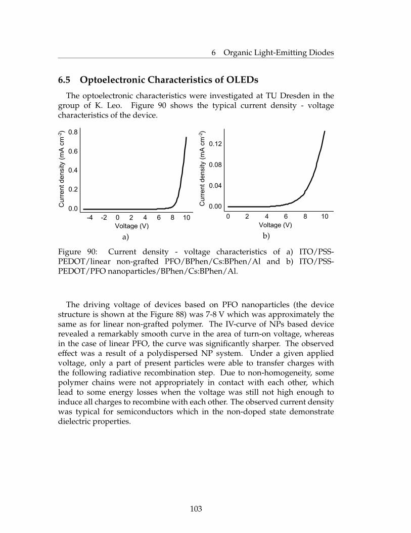
6 Organic Light-Emitting Diodes
6.5 Optoelectronic Characteristics of OLEDs
The optoelectronic characteristics were investigated at TU Dresden in thegroup of K. Leo. Figure 90 shows the typical current density - voltagecharacteristics of the device.
Voltage (V)
Cu
rren
t de
nsity (
mA
cm
)
-2
-4 -2 0 2 4 6 8 10
0.0
0.2
0.4
0.6
0.8
a)Voltage (V)
Cu
rren
t de
nsity (
mA
cm
)
-2
0 2 4 6 8 10
0.00
0.04
0.08
0.12
b)
Figure 90: Current density - voltage characteristics of a) ITO/PSS-PEDOT/linear non-grafted PFO/BPhen/Cs:BPhen/Al and b) ITO/PSS-PEDOT/PFO nanoparticles/BPhen/Cs:BPhen/Al.
The driving voltage of devices based on PFO nanoparticles (the devicestructure is shown at the Figure 88) was 7-8 V which was approximately thesame as for linear non-grafted polymer. The IV-curve of NPs based devicerevealed a remarkably smooth curve in the area of turn-on voltage, whereasin the case of linear PFO, the curve was significantly sharper. The observedeffect was a result of a polydispersed NP system. Under a given appliedvoltage, only a part of present particles were able to transfer charges withthe following radiative recombination step. Due to non-homogeneity, somepolymer chains were not appropriately in contact with each other, whichlead to some energy losses when the voltage was still not high enough toinduce all charges to recombine with each other. The observed current densitywas typical for semiconductors which in the non-doped state demonstratedielectric properties.
103

6 Organic Light-Emitting Diodes
Possibly, due to the fast degradation process (almost no emmision wasdetected already after 1 minute) we were not able to detect luminance versusvoltage characteristics. Nevertheless, Figure 91 illustrates device switched tothe working regime. Here one can observe the light emitted in a blue region.
Figure 91: Picture of OLED based on a PFO NPs emitting layer in a workingregime.
6.6 Conclusions
It was demonstrated that the NPs covered with a polymer brush surfacewere suitable for use in optoelectronic devices such as OLEDs. We have shownthat particles with grafted polymer brushes can be used as an emitting layer.Unfortunately, we did not observe any reliable electroluminescence efficiency,due to inappropriate device performance. It is well known that highly brightand efficient PLEDs based on PF derivatives can be fabricated using calcium asa cathode [177, 178]. Despite of that, the polymer structures developed hereinare promising materials for the manufacturing of optoelectronic devices. Thereis a great potential to control the properties via tuning of the molecularstructure of the core-components which can be replaced by substances withvarious properties.
104

6 Organic Light-Emitting Diodes
6.7 Experimental Part
Materials. The ITO glass (TFD, Inc.) was cleaned by sonication in alcohol toremove all oil dust then treated with mixture of NH4OH:H2O2:H2O (1:1:2) at80◦C during 1 hour and finally rinsed in Millipore water (18 MQxcm) severaltimes. Purified ITO samples were dried by nitrogen and used immediately.
Preparation of the device. PSS-PEDOT (poly(3,4-ethylenedioxythoiphene)doped with poly(styrene sulfonate); Baytron P AI4083) was ultrasonicatedfor 15 minutes and spin-coated on the ITO surface to have the thicknessof 35 nm and backed at 120◦C for 30 min. Dispersion of PS(Br)-core PFO-shell and solution of linear PFO in chloroform were spin-coated (10 mg/ml,2000 rpm) to have the thickness of 90 nm. Finally, the device was completedby thermal evaporation at a pressure of 2x10⁻⁶ torr of pure BPhen, BPhendoped with caesium (Cs:BPhen), and aluminium (Al), of which the thicknessesare 10, 100 and 100 nm, respectively. Active area of all fabricated deviceswas 0.16 cm2 which thereupon was encapsulated and electrical measurementswere performed.
105
7 General Conclusions and Outlook
7 General Conclusions and Outlook
The main aim of this work, which was the synthesis of covalently graftedconjugated polymer brushes on solid substrates using a "grafting from"approach, was successfully performed.
During the course of this work, the process of surface-initiated polycon-densation was investigated. The newly developed method to selectively graftconjugated polymers from different substrates such as Si-wafers, quartz slidesor modificated nanoparticles allowed us to produce different architectureswhich were earlier possible to prepare only non-conductive polymers.Exposure of the substrate with an activated surface layer into the monomersolution produced polymer brushes in a very economical way. Since onlymonomer was consumed for grafting from the surface.
The grafting process was extensively investigated by different methods,and the thickness of the obtained poly(fluorene) films was elucidated byNull-ellipsometry and confirmed by the AFM scratch-test. Preliminarycharacteristics of the device, based on PS(Br)-core poly(octylfluorene)-shell nanoparticles, showed satisfactory results (such as turn-on voltageand electroluminescence in a blue region). They could be improvedby replacement of the insulating PS(Br)-core of nanoparticles with othersubstances (semiconductive, etc.). There is still plenty of room for furtherdevelopment and improvement of the synthesis of poly(fluorene)-basedpolymer brushes.
The polymer structures developed in this work can be utilized as anactive layer in lab-on-chip devices. Alkyl groups in the 9th position ofthe poly(fluorene) monomer unit can be replaced by tailored receptors todetect specific species including small molecules, metal ions and biomoleculesdue to enhanced sensitivity through sensory signal amplification. Post-polymerization modifications may lead to highly water-swellable conjugatedpolyelectrolyte brushes. Also, polymerization of initially optically activefluorene-monomers may be the crucial step to the generation of a light sourcedevices with a large degree of circularly polarized electroluminescence. Thisis of great interest for utilization as backlight for liquid crystalline displays.We believe that the utilization of covalently surface-immobilized conjugatedpolymers may have a great impact on the development of present-daytechnological processes.
106

Abbreviations
AFM Atomic Force MicroscopyATRP Atom Transfer Radical PolymerizationBINAP 2,2′-Bis(diphenylphosphino)-1,1’-binaphthylBPhen 4, 7-Diphenyl-1,10-phenanthrolinet-Bu-PBD 2-(4-Biphenylyl)-5-(p-tert-butylphenyl)-1,3,4-oxadiazoleCOD CyclooctadieneCP Conjugated PolymersDLS Dynamic Light ScatteringDP Degree of Polymerizationdppb 1,4-Bis(diphenylphosphino)butanedppe 1,2-Bis(diphenylphosphino)ethanedppf 1,1′-Bis(diphenylphosphino)ferrocenedppp 1,3-Bis(diphenylphosphino)propaneEL ElectroluminescenceETL Electron-transport LayerGPC Gel Permission ChromatographyGRIM Grignard Metathesis MethodHOMO Highest Occupied Molecular OrbitalHT HexylthiopheneHTL Hole-transport LayerIL Ionic LiquidITO Indium-tin OxideLED Light-Emitting DiodeLUMO Lowest Unoccupied Molecular OrbitalMW Molecular WeightNi(PPh3)4 Tetrakis (triphenylphosphine) Nikel(0)NMP Nitroxide Mediated PolymerizationNMR Nuclear Magnetic ResonanceNP Nanoparticleα-NPD 4,4-Bis[N-(1-naphthyl)-N-phenyl-amino]biphenylOLED Organic Light-Emitting DiodeOXD-7 1,3-Bis[(p-tert-butyl)phenyl-1,3,4-oxadiazoyl]benzenePAMAM Poly(amidoamine)PANI-PSS Polyaniline-poly(styrene sulfonate)Pd2(dba)3 Tris(dibenzylideneacetone) dipalladium(0)PDI Polydispersity IndexPd(OAc) Palladium(II) acetatePd(PtBu3)2 Bis(tri-tert-butylphosphine) Palladium(0)Pd(PPh3)4 Tetrakis (triphenylphosphine) Palladium(0)PEG Polyethylene Glycol
107
PF Poly(fluorene)PF2/6 Poly[9,9-bis(2-ethylhexyl)fluorene]PFO Poly(9,9-dioctyl fluorene)PGMA Poly(glycidyl methacrylate)P3HT Poly(3-hexylthiophene)PL PhotoluminescencePLED Polymer Light-Emitting DiodePPP Poly(phenyl phenylene)PPV Poly(phenyl vinylene)PS PolystyrenePS(Br) Poly(4-bromostyrene)PSS-PEDOT Poly(3,4-ethylenedioxythiophene) poly(styrenesulfonate)PT PolythiophenePV PhotovoltaicPVK Poly(vinyl carbazole)PVK(Br) Poly-(4-bromo-vinylcarbazole)PVP Poly(vinyl pyridine)Py PyridineQE Quantum EfficiencyRAFT Reversible Addition-Fragmentation chain TransferRMS Root Mean SquareROMP Ring Opening Metathesis PolymerizationSAM Self-Assembled MonolayerSEM Scanning Electron MicroscopeSIP Surface-Initiated PolymerizationSPM Scanning Probe MicroscopySTM Scanning Tunneling MicroscopeTAZ 3-Phenyl-4-(1′-naphthyl)-5-phenyl-1,2,4-triazoleTCTA 4,4′,4′′-Tris(N-carbazolyl)-triphenylamineTEM Transmission Electron MicroscopyTGA Thermogravimetric AnalysisTMOS Tetramethyl OrthosilicateTOF Turn Off FrequencyTPD N,N′-Diphenyl-N,N1-(3-methylphenyl) -[1,1′-biphenyl]-4,4′-diamineUV-vis UltravioletvisibleXPS X-Ray Photoelectron Spectroscopydg Interval between the grafting points of tethered chainsrg Radius of gyrationr.t. Room Temperature
108

Acknowledgments
The writing of a dissertation can be a lonely and isolating experience, yetit is obviously not possible without the personal and practical support ofnumerous people.
Firstly, I would like to thank Prof. Dr. Manfred Stamm for giving me theopportunity to work with his group. Also, I would like to thank Dr. AntonKiriy for being a great advisor. His ideas and tremendous support had a majorinfluence on this thesis. Thanks a lot to Dr. Volodymyr Senkovskyy for hisalways great advices as well as his unforgettable jokes.
I also would like to thank Bettina Pilch and Dr. Ulrich Oertel for the UV-vis.measurements. Many thanks to Dr. Hartmut Komber for measuring the NMRspectra and helping in their interpretation. Furthermore, thanks to PetraTreppe for measurements GPC. I am also thankful to Dr. Frank Simon forthe XPS measurments. Thanks a lot to Andreas Janke for providing me withAFM measurments along with exciting flying over the Pirna.
Thanks a lot to Dr. Björn Lüssem and Michael Thomschke from group ofProf. Dr. Karl Leo for good collaboration and a nice electronic measurements.
I would like to thank all my colleags and friends in Germany fortheir help during experiments, fruitfull discussions and of course very nicemoments we spent together: Dr. Vera Bocharova, Dr. Konstantin Demidenok,Marta Horecha, Andrey Horechyy, Dr. Tatyana Beroyzkina, Dr. NatalyaKhanduyeva, Dr. Roman Tkachov, Ekaterina Svetushkina, Ivan Raguzin,Nikolay Puretskiy.
I would like to thank Viktar Khutko, my very best friend, who did a greatjob helping me a lot with making up of my thesis. Besides that, thank you,Vitya, for supporting me during all my PhD.
Of course the years before I started my PhD were crucial for my subsequentprofessional development. Anastasiya Kiprianova and Aleksey Trukhin, whoare very close to me, have played a major role in it. They have turn my hate tochemistry into completely opposite direction.
Warmest thanks and my love to my mother Irina for her love, support andunderstanding.
Last but not least, I would like to thank all fellow students and colleaguesfrom IPF for the fruitful collaborations and equally important the great time inDresden.
109
References
[1] Senkovskyy V., Khanduyeva N., Komber H., Oertel U., Stamm M.,Kuckling D., and Kiriy A. J. Am. Chem. Soc., 129:6626, 2007.
[2] Chiang C.K., Druy M.A., Gan S.C., Heeger A.J., Louis E.J., McDiarmidA.G., Park Y.W., and Schirakawa H. J. Am. Chem. Soc., 100:1013, 1978.
[3] Berlin A.A. J Polym Sci, 55:621, 1961.
[4] Berlin A.A., Popova Z.V., and Yanovskii D.M. Vysokomol Soedin, 7:623,1965.
[5] Speight J.G., Kovacic P., and Koch F.W. J Macromol Sci C, 5:295, 1971.
[6] Jones M.B., Kovacic P., and Howe R.F. Polym Prepr Am Chem Soc, 21:259,1980.
[7] Wessling R.A. and Zimmerman R.G. US Patent, 3,401,152, 1968.
[8] Wessling R.A. J Polym Sci Polym Symp, 72:55, 1985.
[9] Geland J., Vanderzande D., and Louvet F. European Patent Appl. EP,644,217, 1995.
[10] Gilch H.G. and Wheelwright W.L. J Polym Sci A-1, 4:1337, 1966.
[11] Papadimitrakopoulos F., Konstadinidis K., Miller T.M., Opila R.,Chandross E.A., and Galvin M.E. Chem. Mater., 6 (9):1563, 1994.
[12] Rehahn M., Schlüter A.D., Wegner G., and Feast W.J. Polymer, 30:1054–1059, 1989.
[13] Leclerc M., Diaz F.M., and Wegner G. Macromol Chem, 190:3105, 1989.
[14] Osterholm J.-E., Laakso J., Nyholm P., Isotalo H., Stubb H., Inganas O.,and Salanek W.R. Synth Met, 28:C435, 1989.
[15] Yoshino K., Nakajima S., Onoda M., and Sugimoto R. Synth Met,28:C349, 1989.
[16] Kocacic P. and Kyriakis A. J Am Chem Soc, 85:454, 1963.
[17] Reddinger J.L. and Reynolds J.R. Adv Polym Sci, 145:58, 1999.
[18] Dong B., Song D., Zheng L., Xu J., and Li N. J Electroanal Chem, 633:63,2009.
[19] McMurry J.E. and Fleming M.P. J Am Chem Soc, 96:4708, 1974.
110
[20] McMurry J.E. Chem Rev, 89:1513, 1989.
[21] Rehahn M. and Schlüter A.D. Macromol Chem Rapid Commun, 11:375,1990.
[22] Doi S., Osada T., Tsuchida Y., Noguchi T., and Ohnishi T. Synth Met,85:1281, 1997.
[23] Hadziionannou G. and van Hutten P.F. Semiconducting Polymers. Wiley,2000.
[24] Lawrence N.J. The Wittig Reactions and Related Methods in Preparation ofAlkenes: A Practical Approach. Oxford University Press, New York, 1996.
[25] Laue T. and Plagens A. Named Organic Reactions, 2nd Ed. John Wiley andSons, 1999.
[26] Horhold H.H. and Helbig M. Macromol Chem Macromol Symp, 12:229,1987.
[27] Grignard V. C.R.Acad Sci, 130:1322, 1900.
[28] McCullough R.D. Adv Mater, 10:93, 1998.
[29] Chen T.A., Wu X.M., and Rieke R.D. J Am Chem Soc, 117:233, 1995.
[30] Wu X.M. and Chen T.A. Macromolecules, 28:2101, 1995.
[31] Heck R.F. J Am Chem Soc, 90:5518, 1968.
[32] Scherf U. Top Curr Chem, 201:164, 1999.
[33] Suzuki A. Pure Appl Chem, 63:419, 1991.
[34] Tanigaki N., Masuda H., and Kaeriyama K. Polymer, 38:1221, 1997.
[35] Remers M., Schulze M., and Wegner G. Macromol Rapid Commun, 17:239,1996.
[36] Stille J.K. Angew Chem Int Ed, 25:508, 1986.
[37] Sonogashira K., Tohda Y., and Hagihara N. Tetrahedron Lett, 16:4467,1975.
[38] Yamamoto T., Hayashi Y., and Yamamoto Y. Bull. Chem Soc. Jpn., 51:2091,1978.
[39] Nothofer H.G., Meisel A., Miteva T., Neher D., Forster M., Oda M.,Lieser G., Sainova D., Yasuda A., Lupo D., Knoll W., and Scherf U.Macromol Symp, 154:139, 2000.
111
[40] Dong C.-G. and Hu Q.-S. J Am Chem Soc, 127:10006, 2005.
[41] Yokoyama A., Suzuki H., Kubota Y., Ohuchi K., Higashimura H., andYokozawa T. J Am Chem Soc, 129 (23):7236, 2007.
[42] Miyakoshi R., Yokoyama A., and Yokozawa T. J Am Chem Soc, 127:17542,2005.
[43] Mao Y. and Lucht B.L. J of Polym Sci: Part A, 42:5538, 2004.
[44] Miyakoshi R., Yokoyama A., and Yokozawa T. J Polym Sci, Part A: PolymChem, 46:753, 2008.
[45] Miyakoshi R., Yokoyama A., and Yokozawa T. Macromol Rapid Commun,25:1663, 2004.
[46] Huang L., Wu S., Qu Y., Geng Y., and Wang F. Macromolecules, 41:8944,2008.
[47] Milner S.T. Science, 251:905, 1991.
[48] Halperin A., Tirrell M., and Lodge T.P. Adv Polym Sci, 100:31, 1992.
[49] Szleofer I. and Carignano M.A. Adv Chem Phys, 94:165, 1996.
[50] de Gennes P.G. J. Phys. (Paris), 37:1445, 1976.
[51] de Gennes P.G. Macromolecules, 13:1069, 1980.
[52] Zhao B. and Brittain W.J. Prog Polym Sci, 25:677, 2000.
[53] Ruhe J., Ballauff M., Dziezok P., Grohn F., and Johannsmann D. AdvPolym Sci, 165:79, 2004.
[54] Minko S. Polym Rev, 46:397, 2006.
[55] Soga K., Zuckermann M.J., and Guo H. Macromolecules, 29:1998, 1996.
[56] Alexander S. J Phys (Paris), 38:983, 1977.
[57] Szleifer I. and Carignano M. Adv Chem Phys, 94:165, 1996.
[58] Zhilina E., Borisov O., Pryamisyn V., and Birshtein T. Macromolecules,24:140, 1991.
[59] Wijmans C., Scheutjens J., and Zhilina E. Macromolecules, 25:2657, 1992.
[60] Milner S., Witten T., and Cates M. Macromolecules, 21:2610, 1988.
112
[61] Parsonage E., Tirrell M., Watanabe H., and Nuzzo R. Macromolecules,24:1987, 1987.
[62] Marra J. and Hair M.L. Colloids Surf, 34:215, 1989.
[63] Guzonas D., Boils D., and Hair M.L. Macromolecules, 24:3383, 1991.
[64] Fleer G.J., Cohen-Stuart M.A., Scheutjens J.M.H., Cosgrovw T., andVincent B. Polymers at interfaces. London: Chapman and Hall, 1993.
[65] Krenkler K.P., Laible R., and Hamann K. Angew Macromol Chem, 53:101,1953.
[66] Tsubokawa N., Hosoya M., Yanadori K., and Sone Y. J Macromol Sci,A27:445, 1990.
[67] Tsubokawa N., Kuroda A., and Sone Y. J Polym Sci, A, 27:1701, 1989.
[68] Bridger K. and Vincent B. Eur Polym J, 16:1017, 1980.
[69] McQuade D.T., Pullen A.E., and Swager T.M. Chem Rev, 100:2537, 2000.
[70] Ho H.A., Dore K., Boissinot M., Bergeron M.G., Tanguay R.M., BoudreauD., and Leclerc M. J Am Chem Soc, 127:12637, 2005.
[71] Hagberg E.C. and Carter K.R. Polymer Prepr, 46:356, 2005.
[72] Beinhoff M., Appapillai A.T., Underwood L.D., Frommer J.E., and CarterK.R. Langmuir, 22:2411, 2006.
[73] Brittain W.J. and Minko S.J. J Polym Sci, Part A: Polym Chem, 45:3505,2007.
[74] Nakashima H., Furukawa K., Ajito K., Kashimura Y., and Torimitsu K.Langmuir, 21:511, 2005.
[75] Liu J., Tanaka T., Sivula K., Alivisatos A.P., and Frechet J.M. J Am ChemSoc, 126:6550, 2004.
[76] Merrifield R. Science, 150:178, 1965.
[77] Yokozawa T., Asai T., Ryuji S. Ishigooka S., and Hiraoka S. J Am ChemSoc, 122:8313, 2000.
[78] Odoi M.Y., Hammer N.I., Sill K., Emrick T., and Barnes M.D. J Am ChemSoc, 128:3506, 2006.
[79] Ogawa K., Chemburu S., Lopez G.P., Whitten D.G., and Schanze K.S.Langmuir, 23:4541, 2007.
113

[80] Edmondson S., Osborne V.L., and Huck W.T.S. Chem Soc Rev, 33:14, 2004.
[81] Iovu M.C., Sheina E.E., Gil R.R., and McCullough R.D. Macromolecules,38:8649, 2005.
[82] Joseph R. Lakowicz. Principles of Fluorescence Spectroscopy. Springer,1999.
[83] Jablonski A. Z Phys, 94:38, 1935.
[84] Stokes G.G. Phil Trans R Soc (London), 142:463, 1852.
[85] Azzam R.M.A. and Bashara N.M. Ellipsometry and Polarized Light. NorthHolland, 1988.
[86] Tompkins H. A User’s Guide to Ellipsometry. Academic Press, San Diego.,1992.
[87] Iyer K. S., Zdyrko B., Malz H., J. Pionteck, and I. Luzinov.Macromolecules, 36(17):6519, 2003.
[88] Binning G., Roher H., Gerber C., and Weibel E. Phys Rev Lett, 49:57, 1982.
[89] Binnig G., Quate C. F., and Gerber Ch. Phys Rev Lett, 56:930, 1986.
[90] Frommer J. An, 31:1298, 1992.
[91] Tsukruk V. Rubber Chemistry and Technology, 14:446, 1998.
[92] Schlüter A.D. J Polym Sci A: Polym Chem, 39:1533, 2001.
[93] Stambuli J.P., Incarnito C.D., Bühl M., and Hartwig J.F. J Am Chem Soc,126:1184, 2004.
[94] Weber S. K., Galbrecht F., and Scherf U. Org Letters, 8:4039, 2006.
[95] Liversedge I.A., Higgins S.J., Giles M., Heeney M., and McCulloch I.Tetrahedron Lett, 47:5143, 2006.
[96] Khanduyeva N., Senkovskyy V., Beryozkina T., Simon F., Nitschke M.,Stamm M., Grötzschel R., and Kiriy A. Macromolecules, 41:7383, 2008.
[97] Khanduyeva N., Senkovskyy V., Beryozkina T., Horecha M., Stamm M.,Ulrich C., Riede M., Leo K., and Kiriy A. J Am Chem Soc, 131:153, 2009.
[98] Bradley D.D.C., Grell M., Long X., Mellor H., Grice A., Inbasekaran M.,and Woo E.P. Opt Probes Conjugated Polym, 254:3145, 1997.
114

[99] Grell M., Bradley D.D.C., Long X., Chamberlain T., Inbasekaran M., WooE.P., and Soliman M. Acta Polymerica, 49(8):439, 1998.
[100] Stöber W. and Fink A. J of Colloid and Interface Sci, page 62, 1968.
[101] Nozawa K., Gailhanou H., Raison L., Sellier E., Delille J.P., and DelvilleM.N. Langmuir, 21:1516, 2005.
[102] Grem G., Leditzky G., Ullrich B., and Leising G. Adv Mater, 4:36, 1992.
[103] Cimrova V., Remmers M., Neher D., and Wegner G. Adv M, 8:146, 1996.
[104] List E.J.W., Guenter R., de Freitas P.S., and Scherf U. Adv Mater, 14:374,2002.
[105] Gaal M., List E.J.W., and Scherf U. Macromole, 36:4236, 2003.
[106] Romaner L., Pogantsch A., de Frietas P.S., Scherf U., Gaal M., Zojer E.,and List E.J.W. Adv Funct Mater, 13:597, 2003.
[107] Forster T. Ann Phys, 2:55, 1948.
[108] Youshida E.J. Polym Sci, 34:2937, 1996.
[109] Zhang X., Tian H., Liu Q., Wang L., Geng Y., and Wang F. J Org Chem,71(11):4332, 2006.
[110] Bhanage B.M. and Arai M. Catal Rev, 43:315, 2001.
[111] Biffis A., Zecca M., and Basato M. J Mol Catal A: Chem, 173:294, 2001.
[112] Garret C.E. Adv Synth Catal, 346:889, 2004.
[113] Li Y., Xiaoyong M. Hong, David M. Collard, and Mostafa A. El-Sayed.Org Lett, 2:2385, 2000.
[114] Li Y., Boone E., and El-Sayed A. Mostafa. Langmuir, 18:4921, 2002.
[115] Narayanan R. and El-Sayed A. Mostafa. J Am Chem Soc, 125:8340, 2003.
[116] Li Y. and El-Sayed A. Mostafa. J Phys Chem B, 105:8938, 2001.
[117] Narayanan R. and El-Sayed A. Mostafa. J Phys Chem B, 108:8572, 2004.
[118] Daniel M.-C. and Astruc D. Chem Rev, 104:293, 2004.
[119] Gittins D.I. and Caruso F. Angew Chem Int Ed, 40:3001, 2001.
[120] Besson C., Finney E.E., and Finke R.R. Chem Mater, 17:4925, 2005.
115

[121] Strimbu L., Liu J., and Kaifer A.E. Langmuir, 19:483, 2003.
[122] Lu F., Ruiz J., and Astruc D. Tetrahedron Lett, 45:9443, 2004.
[123] Tatumi R., Akita T., and Fujihara H. Chem Comm, page 3349, 2006.
[124] Han W., Liu C., and Jin Z.-L. Org Lett, 9(20):4005, 2007.
[125] Zhao D., Fei Z., Geldbach T., Scopelliti R., and Dyson P.J. J Am Chem Soc,126:15876, 2004.
[126] Lang H.-F., May R.A., Iversen B.L., and Chandler B.D. J Am Chem Soc,125:14832, 2003.
[127] Lang H.-F., Maldonado S., Stevenson K.J., and Chandler B.D. J Am ChemSoc, 126:12949, 2004.
[128] Schauermann S., Hoffmann J., Johanek V., Hartmann J., Libuda J., andFreund H.-J. Angew Chem Int Ed, 41:2532, 2002.
[129] Heemeier M., Carlsson A.F., Naschitzki M., Schmal M., Baumer M., andFreund H.-J. Angew Chem Int Ed, 114:4242, 2002.
[130] Ebitani K., Fujie Y., and Kaneda K. Langmuir, 15:190, 1999.
[131] Djakovitch L. and Kohler K. J Am Chem Soc, 123:5990, 2001.
[132] Prockl S., Kleist W., Gruber M.A., and Kohler K. Angew Chem Int Ed,43:1881, 2004.
[133] Mori K., Hara T., Mizugaki T., Ebitani K., and Kaneda K. J Am Chem Soc,126:10657, 2004.
[134] Choudary B.M., Mahdi S., Chowdari N.S., Kantam M.L., and StreedharB. J Am Chem Soc, 124:14127, 2002.
[135] Bertarione S., Scarano D., Zecchina A., Johanek V., Hoffmann J.,Schauermann S., Libuda J., Rupprechter G., and Freund H.-J. J Catal,123:64, 2004.
[136] Caruso F., Caruso R.A., and Mohwald H. Science, 282:1111, 1998.
[137] Caruso F. Adv Mater, 13:11, 2001.
[138] Kim S.-W., Kim M., Lee W.Y., and Hyeon T. J Am Chem Soc, 124:7642,2002.
[139] Marck G., Villiger A., and Buchker R. Tetrahedron Lett, 35:3277, 1994.
116

[140] Wallow T.I. and Novak B.M. J Org Chem, 59:5034, 1994.
[141] Reetz M.T. and Westermann E. Angew Chem Int Ed, 39:165, 2000.
[142] Sakurai H., Tsukuda T., and Hirao T. J Org Chem, 67:2721, 2002.
[143] Hu J. and Liu Y.B. Langmuir, 21:2121, 2005.
[144] Beller M., Fischer H., Kuhlein K., Reisinger C.P., and Herrmann W.A. JOrganomet Chem, 520:257, 1996.
[145] Zhao F., Murakami K., Shirai M., and Arai M. J Catal, 194:479, 2000.
[146] Whitesides G.M., Hackett M., Brainard R.L., Lavalleye J.P.P.M.,Sowinski A.F., Izumi A.N., Moore S.S., Brown D.W., and Staudt E.M.Organometallics, 4:1819, 1985.
[147] Crabtree R.H., Mellea M.F., Mihelcic J.M., and Quirk J.M. J Am Chem Soc,104:107, 1982.
[148] Collman J.P., Kosydar K.M., Bressan M., Lamanna W., and Garret T. JAm Chem Soc, 106:2569, 1984.
[149] Leadbeater N.E. and Marco M. J Org Chem, 68:5660, 2003.
[150] Leadbeater N.E. and Marko M. Angew Chem Int Ed, 42:1407, 2003.
[151] Arvela R.K., Leadbeater N.E., Sangi M.S., Williams V.A., Granados P.,and Singer R.D. J Org Chem, 70:161, 2005.
[152] Sheldon R.A., Wallau M., Arendes I.W.C.E., and Schuchardt U. Acc ChemRes, 31:485, 1998.
[153] Zhao F.Y., Bhanage B.M., Shirai M., and Arai M. Chem Eur J, 6:843, 2000.
[154] Zhao F.Y., Shirai M., and Arai M. J Mol Catal A: Chem, 154:39, 2000.
[155] Laine R.M. J Mol Catal, 14:137, 1982.
[156] Lin Y. and Finke R.G. Inorg Chem, 33:4891, 1994.
[157] Yu K.Q., Sommer W., Richardson J.M., Weck M., and Jones C.W. AdvSynth Catal, 347:161, 2005.
[158] Eberhard M.R. Org Lett, 6:2125, 2004.
[159] Olsson D., Nilsson P., El Masnaouy M., and Wendt O.F. Dalton Trans,page 1924, 2005.
117

[160] Astruc D., Lu F., and Ruiz J.A. Angew Chem Int Ed, 44:7399, 2005.
[161] De Vries J.G. Dalton Trans, page 421, 2006.
[162] Tamura M. and Fujihara H. J Am Chem Soc, 125:15742, 2003.
[163] Senkovskyy V., Tkachov R., Beryozkina T., Komber H., Oertel U.,Horecha M., Bocharova V., Stamm M., Gevorgyan S.A., Krebs F.C., andKiriy A. J Am Chem Soc, 131:16445, 2009.
[164] Tkachev R., Senkovskyy V., Horecha M., Oertel U., Stamm M., and KiriyA. Chem Comm, 46:1425, 2010.
[165] Brinkmann M. Macromolecules, 40:7532, 2007.
[166] Krebs F.C., Nyberg R.B., and Jorgesen M. Chem Mater, 16:1313, 2004.
[167] Nielsen K.T., Bechgaard K., and Krebs F.C. Macromolecules, 38:658, 2005.
[168] Karg S., Scott J.C., Salem J.R., and Angelopoulos M. Synth Met, 80:111,1996.
[169] Yang Y., Westerweele W., Zhang C., Smith P., and Heeger A.J. J ApplPhys, 77:695, 1995.
[170] Gao Y., Heeger A.J., Lee J.Y., and Kim C.Y. Synth Met, 82:221, 1996.
[171] Cao Y., Yu G., Zhang C., Menon R., and Heeger A.J. Synth Met, 87:171,1997.
[172] Brown T.M., Kim J.S., Friend R.H., Cacialli F., Daik R., and Feast W.J.Appl Phys Lett, 75:1679, 1999.
[173] Yan H., Huang Q., Scott B.J., and Marks T.J. Appl Phys Lett, 84:3873, 2004.
[174] Choulis S.A., Choong V.E., Mathai M.K., and So F. Appl Phys Lett,87:113503, 2005.
[175] Seo S.M., Kim J.H., Park J.Y., and Lee H.H. Appl Phys Lett, 87:183503,2005.
[176] Zhang C., Yu G., and Cao Y. US Patent, page 5798170, 1998.
[177] Grice A.W., Bradley D.D.C., Bernius M.T., Inbasekaran M., Wu W.W.,and Woo E.P. Appl Phys Lett, 73:629, 1998.
[178] Weinfurtner K.-H., Fujikawa H., Tokito S., and Taga Y. Appl Phys Lett,76:2502, 2000.
118
Curriculum Vitae
Boyko Kseniya
Personal
• Born on February 18, 1985.
• Russian nationality.
Qualification
since 07.2007 PhD student in the department of Chemistry of TechnicalUniversity of Dresden (Supervisor: Prof. M. Stamm)
09.2002-06.2007 M.S. degree (in chemistry) at the Department ofChemistry of Saint-Petersburg State University
09.1999-06.2002 Gymnasium Nr. 45, Saint Petersburg, Russia
09.1992-06.1999 Secondary school Nr. 23, Vladivostok, Russia
119
Versicherung
Hiermit versichere ich, dass ich die vorliegende Arbeit ohne unzulässigeHilfe Dritter und ohne Benutzung anderer als der angegebenen Hilfsmittelangefertigt habe; die aus fremden Quellen direkt oder indirekt übernommenenGedanken sind als solche kenntlich gemacht. Die Arbeit wurde bisherweder im Inland noch im Ausland in gleicher oder ähnlicher Form eineranderen Prüfungsbehörde vorgelegt. Die vorliegende Arbeit wurde unterder wissenschaftlichen Betreuung von Prof. Dr. Manfred Stamm andem Leibniz-Institut für Polymerforschung Dresden angefertigt. Keinefrühere erfolglose Promotionsverfahren statt gefunden haben. Ich erkennedie Promotionsordnung der Technischen Universität Dresden der FakultätMathematik und Naturwissenschaft vom 16.04.2003 an.
Boyko Kseniya
Dresden
120