sushant 131119022958-phpapp02
TRANSCRIPT
INSTITUTE OF ENGEENIRRING AND TECHNOLOGY
DR.RAM MANOHAR LOHIYA AVADH UNIVERSITY, FAIZABAD
Batch- 2009-2013
Project Report On Automatic Plant Irrigator
A Partial fulfillment for the award of degree in bachelor of
technology in electronics and communication engineering
Submitted To: Submitted By: H.O.D(ECE) Guided By: Sushant Shankar[9255] Miss Sweta Shrivastava 3rd Year ECE
Signature - …………………. Date-…………………….
CERTIFICATE
This is to certify that Sushant Shankar student of B.Tech. 3rd year from
Institute of Engineering and Technology, Dr. Ram Manohar Lohiya Avadh
University,Faizabad successfully submitted his project report on Automatic
Plant Irrigator.
Date-………………………..
Signature of the Guide

Acknowledgement
“It is not possible to prepare a summer training report without the assistance &
encouragement of other people. This one is certainly no exception.”
On the very outset of this report, I would like to extend my sincere & heartfelt obligation
towards all the personages who have helped me in this endeavor. Without their active
guidance, help, cooperation & encouragement, I would not have made headway in the
project.
First and foremost, I would like to express my sincere gratitude to my guide, Miss Sweta
Shrivastava I was privileged to experience a sustained enthusiastic and involved interest
from his side. This fuelled my enthusiasm even further and encouraged me to boldly step
into what was a totally dark and unexplored expanse before me. He always fuelled my
thoughts to think broad and out of the box. I would also like to thank HOD(ECE) who,
instead of his busy schedule, always guided me in right direction. I would like to thank all the
staff member for motivation guidance and support .
Thanking You
Sushant Shankar

Table of Contents
1. Abstract..........................................................................1
2. Motivation.......................................................................2
3. Technical specification………………………………………………………………….3
4. Introduction……………...........................................................4
5. Block Diagram………………………................................................5
6. Power supply….................................................................6
7. Transformer……………............................................................7
8. Rectifier .........................................................................8
9. Relays ……………..................................................................9
10. Advantage ………..............................................................10
11. Application………………………………………......................................13

ABSTRACT
The motivation for this project came from the countries where economy is based on agriculture and the climatic conditions lead to lack of rains & scarcity of
water. The farmers working in the farm lands are solely dependent on the rains and bore wells for irrigation of the land. Even if the farm land has a water-pump, manual intervention by farmers is required to turn the pump on/off whenever needed.
The aim of our project is to minimize this manual intervention by the farmer. Automated Irrigation system will serve the following purposes: 1) As there is no un-planned usage of water, a lot of water is saved from
being wasted. 2) The irrigation is the only when there is not enough moisture in the soil and
the sensors decides when should the pump be turned on/off, saves a lot time for the farmers. This also gives much needed rest to the farmers, as they don’t have to go and turn the pump on/off manually.
1
Motivation
The increasing demand of the food supplies requires a rapid improvement in food production technology. In many countries where agriculture plays an important part in shaping up the economy and the climatic conditions are isotropic, but still we are not able to make full use of agricultural resources. One of the main reasons is the lack of rains & scarcity of land reservoir water. Extraction of water at regular intervals from earth is reducing the water level as a result of which the zones of un-irrigated land are gradually increasing.
Also, the unplanned use of water inadvertently results in wastage of water. In an Automated Irrigation System, the most significant advantage is that water is supplied only when the moisture in soil goes below a pre-set threshold value. This saves us a lot of water. In recent times, the farmers have been using irrigation technique through the manual control in which the farmers irrigate the land at regular intervals by turning the water-pump on/off when required. This process sometimes consumes more water and sometimes the water supply to the land is delayed due to which the crops dry out. Water deficiency deteriorates plants growth before visible wilting occurs. In addition to this slowed growth rate, lighter weight fruit follows water deficiency.
This problem can be perfectly rectified if we use Automated Irrigation System in which the irrigation will take place only when there will be intense requirement of water, as suggested by the moisture in the soil
2
TECHNICAL SPECIFICATION
Title of the project : Intelligent Automatic Plant Irrigation System with water pump
control based on soil moister condition System.
Power Supply : +5V, 500mA Regulated Power Supply
Sensors : copper probe
Load : pumps
Relay
IC : LM324,NE555{timer IC}
LED
Applications : Industrial and House Hold Applications
3
Introduction
Irrigation is the key to a successful garden. Long gone are the days of manual watering or relying on a friend to water when you are on vacation or away on business. The Project presented here waters your plants regularly when you are out for vocation. The circuit comprises sensor parts built using op-amp IC LM324. Op-amp is configured here as a comparator. Two stiff copper wires are inserted in the soil to sense the whether the Soil is wet or dry. The comparator monitors the sensors and when sensors sense the dry condition then the project will switch on the motor and it will switch off the motor when the sensors are in wet. The comparator does the above job it receives the signals from the sensors. A transistor is used to drive the relay during the soil wet condition. 5V double pole – double through relay is used to control the water pump. LED indication is provided for visual identification of the relay / load status. A switching diode is connected across the relay to neutralize the reverse EMF. This project works with 5V regulated power supply. Power on LED is connected for visual identification of power status. This project uses regulated 5V, 750mA power supply. 7805 three terminal voltage regulator is used for voltage regulation. Bridge type full wave rectifier is used to rectify the ac output of secondary of 230/18V step down transformer.
4

Block Digram
Timer Based Industrial Liquid Pump Controller with different time slots
5

Circuit Diagram
6

POWER SUPPLY
The input to the circuit is applied from the regulated power supply. The a.c. input i.e., 230V from the mains supply is step down by the transformer to 12V and is fed to a rectifier. The output obtained from the rectifier is a pulsating d.c voltage. So in order to get a pure d.c voltage, the output voltage from the rectifier is fed to a filter to remove any a.c components present even after rectification. Now, this voltage is given to a voltage regulator to obtain a pure constant dc voltage.
7
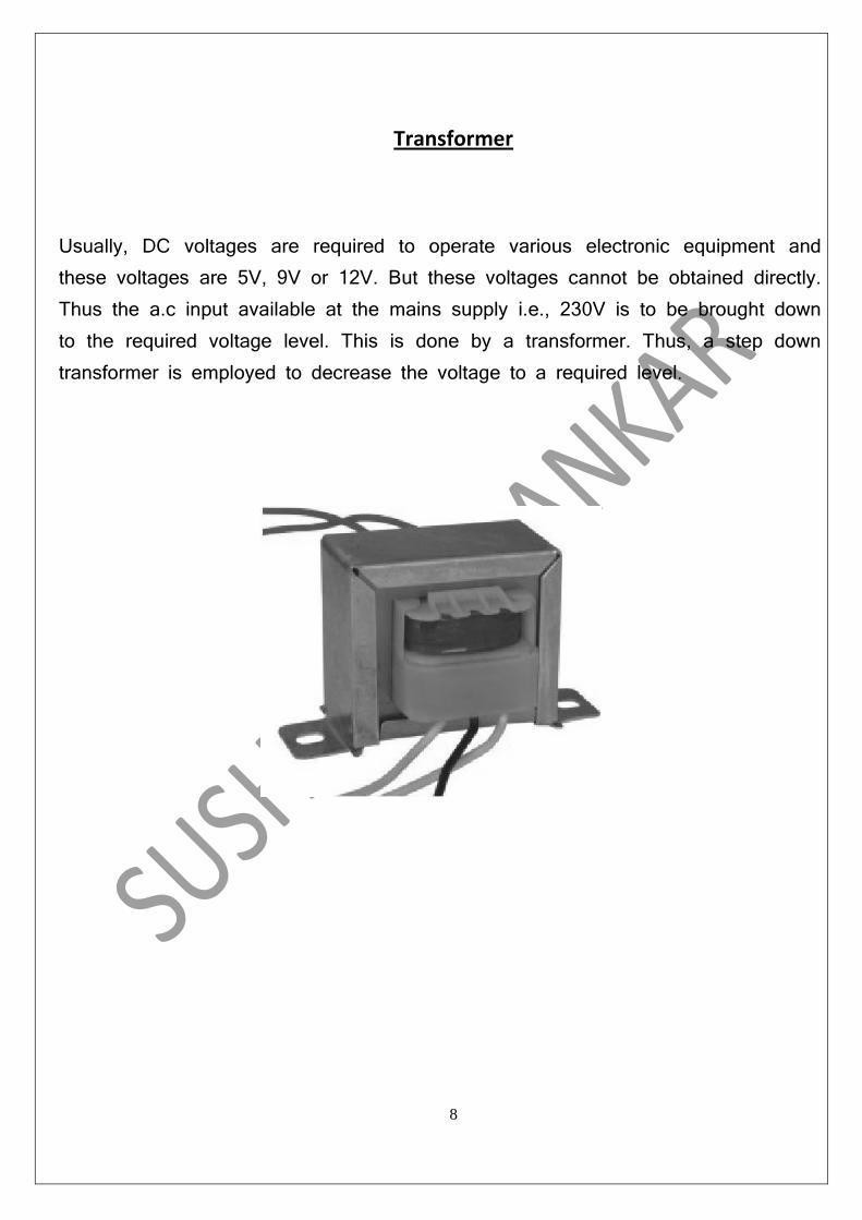
Transformer
Usually, DC voltages are required to operate various electronic equipment and these voltages are 5V, 9V or 12V. But these voltages cannot be obtained directly. Thus the a.c input available at the mains supply i.e., 230V is to be brought down to the required voltage level. This is done by a transformer. Thus, a step down transformer is employed to decrease the voltage to a required level.
8
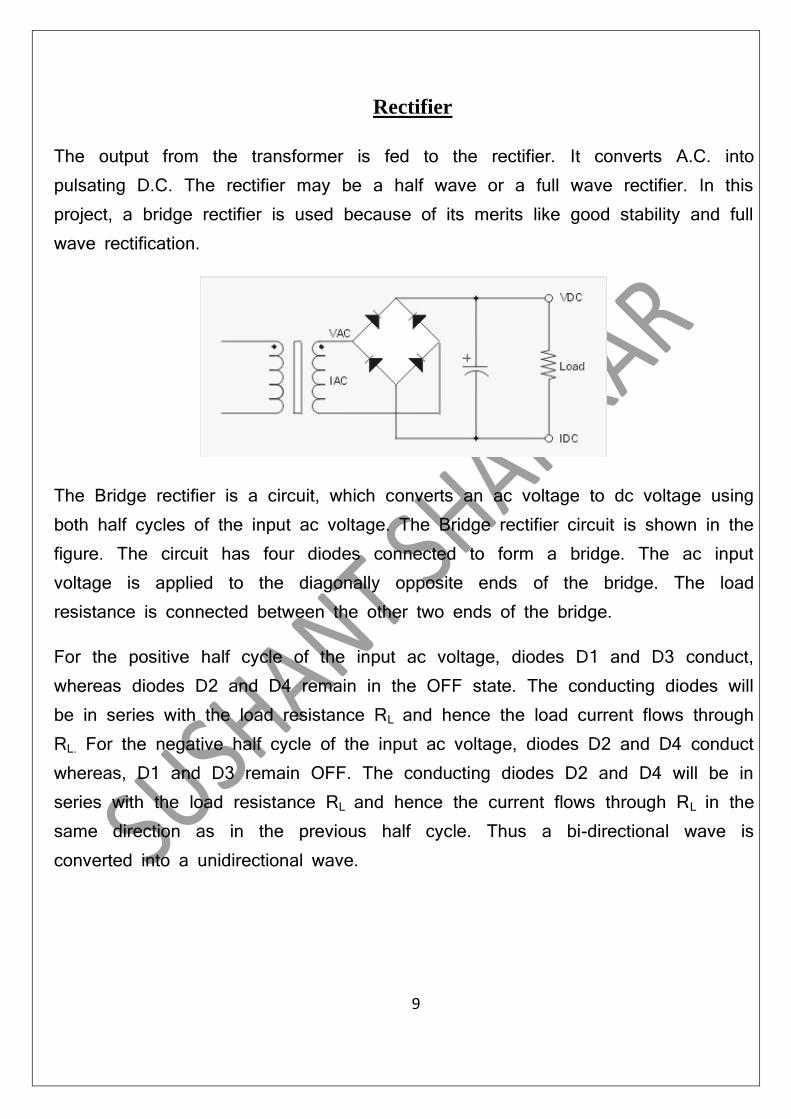
Rectifier
The output from the transformer is fed to the rectifier. It converts A.C. into pulsating D.C. The rectifier may be a half wave or a full wave rectifier. In this project, a bridge rectifier is used because of its merits like good stability and full wave rectification.
The Bridge rectifier is a circuit, which converts an ac voltage to dc voltage using both half cycles of the input ac voltage. The Bridge rectifier circuit is shown in the figure. The circuit has four diodes connected to form a bridge. The ac input voltage is applied to the diagonally opposite ends of the bridge. The load resistance is connected between the other two ends of the bridge.
For the positive half cycle of the input ac voltage, diodes D1 and D3 conduct, whereas diodes D2 and D4 remain in the OFF state. The conducting diodes will be in series with the load resistance RL and hence the load current flows through RL. For the negative half cycle of the input ac voltage, diodes D2 and D4 conduct whereas, D1 and D3 remain OFF. The conducting diodes D2 and D4 will be in series with the load resistance RL and hence the current flows through RL in the same direction as in the previous half cycle. Thus a bi-directional wave is converted into a unidirectional wave.
9

Filter
Capacitive filter is used in this project. It removes the ripples from the output of rectifier and smoothens the D.C. Output received from this filter is constant until the mains voltage and load is maintained constant. However, if either of the two is varied, D.C. voltage received at this point changes. Therefore a regulator is applied at the output stage.
10

Voltage regulator
As the name itself implies, it regulates the input applied to it. A voltage regulator is an electrical regulator designed to automatically maintain a constant voltage level. In this project, power supply of 5V and 12V are required. In order to obtain these voltage levels, 7805 and 7812 voltage regulators are to be used. The first number 78 represents positive supply and the numbers 05, 12 represent the required output voltage levels. The L78xx series of three-terminal positive regulators is available in TO-220, TO-220FP, TO-3, D2PAK and DPAK packages and several fixed output voltages, making it useful in a wide range of applications. These regulators can provide local on-card regulation, eliminating the distribution problems associated with single point regulation. Each type employs internal current limiting, thermal shut-down and safe area protection, making it essentially indestructible. If adequate heat sinking is provided, they can deliver over 1 A output current. Although designed primarily as fixed voltage regulators, these devices can be used with external components to obtain adjustable voltage and currents.
11

RELAYS
“A relay is an electrically controllable switch widely used in industrial controls,
automobiles and appliances.”
The relay allows the isolation of two separate sections of a system with two different voltage sources i.e., a small amount of voltage/current on one side can handle a large amount of voltage/current on the other side but there is no chance that these two voltages mix up.
Inductor
Fig: Circuit symbol of a relay
Operation- when current flows through the coil, a magnetic field are created around the coil i.e., the coil is energized. This causes the armature to be attracted to the coil. The armature’s contact acts like a switch and closes or opens the circuit. When the coil is not energized, a spring pulls the armature to its normal state of open or closed. There are all types of relays for all kinds of applications.
Transistors and ICs must be protected from the brief high voltage 'spike' produced when the relay coil is switched off. The above diagram shows how a signal diode (eg 1N4148) is connected across the relay coil to provide this protection. The diode is connected 'backwards' so that it will normally not conduct. Conduction occurs only when the relay coil is switched off, at this moment the current tries to flow continuously through the coil and it is safely diverted through the diode. Without the diode no current could flow and the coil would produce a damaging

high voltage 'spike' in its attempt to keep the current flowing.In choosing a relay, the following characteristics need to be considered:
The contacts can be normally open (NO) or normally closed (NC). In the NC type, the contacts are closed when the coil is not energized. In the NO type, the
contacts are closed when the coil is energized.
Fig: Relay Operation and use of protection diodes
2. There can be one or more contacts. i.e., a different type like SPST (single pole single throw), SPDT (single pole double throw) and DPDT (double pole double throw) relays.
3. The voltage and current required to energize the coil. The voltage can vary from a few volts to 50 volts, while the current can be from a few milliamps to 20milliamps. The relay has a minimum voltage, below which the coil will not be energized. This minimum voltage is called the “pull-in” voltage.
4. The minimum DC/AC voltage and current that can be handled by the contacts. This is in the range of a few volts to hundreds of volts, while the current can be from a few amps to 40A or more, depending on the relay.
13
Advantages:
Highly sensitive Works according to the soil condition Fit and Forget system Low cost and reliable circuit Complete elimination of manpower Can handle heavy loads up to 7A System can be switched into manual mode whenever required
Applications :
Roof Gardens
Lawns
Agriculture Lands
Home Gardens
14