survey of routing protocols in cognitive radio...
TRANSCRIPT

Survey of Routing Protocols in Cognitive Radio Networks
Samar Abdelaziza,1,, Mustafa ElNainay b,1,
aComputer and Systems Engineering Department, Alexandria University, EgyptbComputer and Systems Engineering Department, Virginia Tech MENA and Alexandria University, Egypt
Abstract
Cognitive radio (CR) technology is introduced to solve the problem of spectrum underutilizationin wireless networks by opportunistically exploiting portions of the spectrum temporarily vacated bylicensed primary users. In this paper, we present a survey of recent routing protocols in Cognitive RadioNetworks (CRNs). We start by listing routing challenges that should be considered for different typesof networks starting by the Wireless Local Area Networks (WLANs) and ending with the CognitiveRadio Networks (CRNs). We then present different routing protocols that are designed for CRNs, wefocus on the distributed protocols in which the spectrum availability information is locally constructedat each secondary user in a distributed manner, and we classify them according to the routing metricinto four main categories: delay based approaches, link stability based approaches, throughput basedapproaches and location based approaches. Finally, possible future research directions are discussed.
Keywords: Cognitive radio networks, Routing protocols, Routing metrics, Routing challenges
1. Introduction
Cognitive radio networks (CRNs) are an emerging multi-hop wireless networking technology wherenodes are able to change their transmission or reception parameters based on interaction with theenvironment in which they operate. Recent spectrum measurements [1] show that the fixed spectrumassignment policy is becoming unsuitable for today’s wireless communication. According to the Fed-eral Communications Commission (FCC) report [2], many spectrum bands allocated through staticassignment policies are used only in bounded geographical areas or over limited periods of time, andthat the average utilization of such bands varies between 15
In order to make good use of the unutilized bands, devices with cognitive capabilities can be net-worked to create Cognitive Radio Network, in which there are two types of users sharing a commonspectrum portion but with different rules: Primary Users (PUs) have the priority in spectrum utiliza-tion within the band they have licensed, and Secondary Users (SUs) must opportunistically access thespectrum without interfering with PUs.
The research in cognitive radio networks is primarily on spectrum sensing techniques and spectrumsharing approaches, spectrum sensing techniques [3, 4, 5, 6, 7] are used to determine which portion ofthe spectrum is available and detect the presence of licensed users when a SU operates in a licensedband in order to avoid any harmful interference to PUs, spectrum sharing [8, 9, 10, 11, 12, 13] seeksto coordinate access to some channel with other users in order to provide fair spectrum schedulingmethod among them. There is very little research on the routing algorithms for CRNs due to themany additional challenges that they face in comparison with traditional wireless networks. In fact,routing problem in cognitive radio networks has similarities with routing in multi-channel, multi-hopad hoc networks, but with the additional challenge of having to deal with the dynamic behavior ofthe PUs, and their effects on changing spectrum opportunities (SOPs) availability of SUs. In last fewyears, many new algorithms have been proposed for the problem of routing in CRNs, and we classify
Email addresses: [email protected] (Samar Abdelaziz ), [email protected] (Mustafa ElNainay )
Preprint submitted to Elsevier October 1, 2012
them in this survey as: delay based, link stability based and throughput based, although there are fewdistinct ones based on maintenance cost or use swarm intelligence algorithms to reduce routing costoverhead and cumulative delay.
The paper is organized as follows. Section 2 gives a summarized history of the wireless networksbeginning with the wireless local area network and ending with the cognitive radio networks. Section 3summarizes the main challenges for routing information through multi-hop CRNs. In Section 4, delaybased approaches are covered. Section 5 describes link stability based approaches. Throughput basedapproaches are explained in Section 6. In Section 7 we give overview of the location based approaches.Finally, section 8 concludes the paper highlighting some open research issues for future investigations.
2. Computer Networks History and Challenges
The history of computer networks is familiar to most computer users. It started in the UnitedStates in the 1960s when computers at some universities were connected, making possible an exchangeof digital information. Different local and wide area networks were established. In the mid-1970s theInternet was launched as a collection of protocols regulating transportation of signals and informationbetween different networks and computer systems. During the Second World War, the United StatesArmy first used radio signals for data transmission. This inspired a group of researchers in 1971 at theUniversity of Hawaii to create the first packet based radio communications network called ALOHNET.ALOHNET was the very first Wireless Local Area Network (WLAN). This first WLAN consisted of 7computers that communicated in a bi-directional star topology.
Moving from wired to wireless networks makes small changes at the network layer, but large changesin the link layer due to the many differences between a wired link and a wireless link that can be listedas follows:
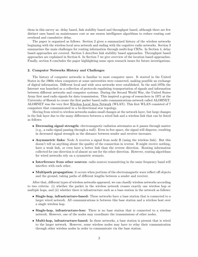
• Decreasing signal strength: electromagnetic radiation attenuates as it passes through matter(e.g., a radio signal passing through a wall). Even in free space, the signal will disperse, resultingin decreased signal strength as the distance between sender and receiver increases.
• Asymmetric links: Node A receives a signal from node B (using the wireless link). But thisdoesn’t tell us anything about the quality of the connection in reverse. B might receive nothing,have a weak link, or even have a better link than the reverse direction. Routing informationcollected for one direction is of almost no use for the other direction. However, routing algorithmsfor wired networks rely on a symmetric scenario.
• Interference from other sources: radio sources transmitting in the same frequency band willinterfere with each other.
• Multipath propagation: it occurs when portions of the electromagnetic wave reflect off objectsand the ground, taking paths of different lengths between a sender and receiver.
After that, different types of wireless networks appeared, we can classify wireless networks accordingto two criteria: (i) whether the packet in the wireless network crosses exactly one wireless hop ormultiple hops, and (ii) whether there is infrastructure such as a base station in the network as follows:
• Single-hop, infrastructure-based: These networks have a base station that is connected to alarger wired network. All communications is between this base station and a wireless host overa single wireless hop.
• Single-hop, infrastructure-less: There is no base station that is connected to a wirelessnetwork. However, one of the nodes may coordinate the transmissions of other nodes.
• Multi-hop, infrastructure-based: In these networks, a base station is present that is wiredto the larger network. However, some wireless nodes may have to relay their communicationthrough other wireless nodes in order to communicate via the base station.
2
• Multi-hop, infrastructure-less: There is no base station in these networks, and nodes mayhave to relay messages among several other nodes in order to reach a destination.Wireless Ad-hoc networks falls in this category.
The history of wireless ad-hoc networks began in 1973 when the U.S. DARPA (Defense AdvancedResearch Projects Agency) initiated a research program for interlinking mobile battlefield elements ina packet-based infrastructure-less and hostile environment called packet radio networks (PRNet). Thenetwork is called ad hoc because the decision on which nodes forward the message is made dynamicallydepending on the current topology.
In addition to communication characteristics changing over time as mentioned for wireless networks,wireless ad hoc networks face additional challenges as follows:
• Energy efficiency: Since ad hoc networks do not assume the availability of a fixed infrastruc-ture, it follows that individual nodes may have to rely on portable, limited power sources. Theidea of energy-efficiency therefore becomes an important problem in ad hoc networks. Most ex-isting solutions for saving energy in ad hoc networks revolve around the reduction of power usedby the radio transceiver. At the MAC level and above, this is often done by selectively sendingthe receiver into a sleep mode, or by selecting routes that require many short hops, instead of afew longer hops.
• Network topology changes: Nodes may fail completely; for instance, they run out of energy,or they are physically destroyed. Also new nodes may be added to the network, or nodes aretaken away.
• Scalability: Scalability in ad hoc networks can be defined as whether the network is able toprovide an acceptable level of service to packets even in the presence of a large number of nodesin the network. This capability is closely related as to how quickly network protocol controloverhead increases as a function of an increase in the number of nodes and link changes. Inproactive networks, scalability is often accomplished by limiting the scope of control updatesto locations close to the changes. In reactive ad hoc networks, techniques such as dynamicallylimiting the scope of route requests and attempting local repairs to broken routes are often used.
Mobile Ad-hoc Networks (MANET) became a research topic in 1990s. The nodes are portabledevices like laptops, PDAs, or cellular phones. Example scenarios are disaster relief operation inareas where no communication infrastructure is available, or car-to-car communication in co-calledVANETs (vehicular ad hoc networks). To achieve mobility, both seamless connectivity and continuousreachability should be provided. Since the standard Internet combines the unique host identifier withthe topology location using IP addresses, it cannot provide support for mobility. Thus, Mobile IP isproposed by IETF to support mobility in IP networks. Mobile IP supports mobility by decouplingthe binding between the host identifier and topology location using a fixed indirection point. Mobilitymanagement in wireless networks involves changing the point of attachment, and hence the IP addressof a mobile node. This adds additional requirements that should be exist for mobile networks:
• Efficient handoff: The performance of a mobility scheme mainly depends on the type of hand-offs it uses. There are two types of handoffs: soft handoff and hard handoff. Soft handoff makes anew connection before disconnecting the previous connection. It allows the mobile node to com-municate with multiple interfaces during handoff, and the communication with the old interfaceis dropped when the signal strength between the old access point drops below a certain threshold.Hard handoff drops the previous connection before making a new connection. Handoffs shouldbe handled efficiently in order to reduce or avoid the loss and delay of packets as possible
• Efficient routing: Packets should be routed with the latency as low as possible, optimally closeto the shortest path provided by IP routing.
• Fault tolerance: A mobility scheme should make the communication between mobile nodes asmuch tolerant to fault as the communication between stationary nodes.
3

• Simultaneous mobility: End hosts may move simultaneously, and the communication betweenthem should not be interrupted.
• Transparency: The mobility scheme should be transparent to applications so that the applica-tions are not aware of the handoff, and thus do not need to be modified for mobility.
Recently, interesting commercial applications of multi-hop wireless networks have emerged. Andit’s observed that in such networks, most of the nodes are either stationary or minimally mobileand do not rely on batteries. Hence, the focus of routing algorithms is on improving the net-work capacity. One of the main problems facing such networks is the reduction in total capacitydue to interference between multiple simultaneous transmissions. Providing each node with multi-ple radios offers a promising solution for improving the capacity of these networks, from here theMulti-hop Multi-channel Wireless Networks appeared in which nodes can receive and transmit simul-taneously using different radios, and hence the network can utilize more of the radio spectrum.
3. Routing Challenges in Cognitive Radio Networks
There are similarities between Cognitive Radio Networks and traditional multi-channel multi-hopad hoc networks, but with the additional challenge of having to deal with the simultaneous transmis-sions of the PUs which dynamically change network topology and SOPs availability; this differenceraises some challenges in CRNs which are not in multi-channel multi-hop networks and can be listedas follows:
• In CRNs, not only nodes’ location but also their communication frequencies affect networkconnectivity, unlike multi-channel multi-hop networks where the distance between nodes is theonly parameter that affects network connectivity.
• Channel availability in CRNs is different from traditional wireless multi-channel multi-hop net-works, nodes have partially overlapping and non-overlapping set of available channels, and thesechannels vary with time according to PU activity at its position.
For the above challenges, spectrum information should be jointly considered in routing, CRNsrouting solutions can be classified into two categories depending on the issue of spectrum-awareness:full spectrum knowledge, and local spectrum knowledge [14]. In the former case, a spectrum occu-pancy map is available to the network nodes or to a central control entity, whereas in the latter case,information on spectrum availability is locally constructed at each secondary user through distributedprotocols. Protocols that are introduced in this survey lie on the second class where the spectrumknowledge is locally constructed at each node. As shown in Figure 1, we categorize the proposedapproaches into four main categories: [1] Delay based approaches in which the delay is used as therouting metric; [2] Link stability based approaches which focus on selecting the most stable routes; [3]Throughput based approaches seek to maximize the throughput; [4] Location based approaches thatmake use of location information to construct routes using nodes that are close to the destination. Thefollowing sections describe the proposed protocols in each category in details.
Figure 1: Classification of routing protocols in CRNs
4

4. Delay Based Approaches
This section overviews routing approaches that measure the quality of routing solutions in termsof delays. End-to-end delay along route is a traditional metric for routing algorithms, while it facesseveral different cases in multi-hop CRN. Delay-aware routing metrics are proposed in [15, 16, 17, 18],which consider different delay components such as:
1. Switching Delay: occurs when a node in a path changes its frequency band.
2. Backoff Delay: MAC protocols result in backoff delay when trying to solve hidden-terminaland exposed-terminal problems (while working on identical frequency band).
3. Queuing Delay: which depends on the transmission capacity of a node on a given frequencyband.
The following subsections give brief description of each protocol that use the delay materic, and specifythe delay components that are used for each of them.
4.1. Joint On-demand Routing and Spectrum Assignment
A Delay motivated On-demand Routing Protocol (DORP) [16] is a delay-based approach thatcombines many delay metrics (switching delay, backoff delay and queuing delay) to efficiently selectminimum end-to-end delay route, the switching and backoff delay along the path or at the intersectingnodes are represented as PATH-delay (DP) and NODE-delay (DN) respectively, they are used toevaluate the cumulative delay of the path. At a relay node m, a metric representing the cumulativedelay along a candidate route is computed as:
Droute,m = DPm +DNm (1)
The PATH-delay (DP) takes into account the switching delay and backoff delay caused by thepath and depends on the frequency bands assigned to all nodes along the path. As a consequence,suppose there are H hops between node m and the destination, we have:
DPm = Dswitching,m +Dbackoff,m (2)
And
Dswitching,i =
H∑j=m
k|Bandj −Bandj+1| (3)
where k is a constant with the suggested value of 10 ms/10 MHz. The backoff delay depends on thebandwidth on the current frequency band, the number of consecutive nodes sharing the same frequency,and the packet size. The derivation of the expression Dbackoff is reported in [16].
The NODE-delay (DN) is caused by existing flows at relaying node; it depends on the numberand frequency bands of traversing flows, and is defined as:
Dnode = Dswitching +Dqueueing +Dbackoff (4)
The frequency band from a node’s active bands is denoted as Bandi. The number of active bandsis assumed to be M and (1iM). The switching delay is formulated as:
Dswitching = 2k.|BandM −Band1| (5)
and becomes a constant when there is no difference in switching from closer frequencies with respectto far away ones. Dbackoff is defined as the time from the moment a packet is ready to be transmittedto the moment the packet starts its successful transmission. The backoff delay on Bandi is obtainedas:
Dbackoff (Numi) =1
(1− pc).[1− (1− pc)1
(Numi−1) ].W0 (6)
5

, where Numi is the number of contending nodes, pc denotes the probability that a contending nodeexperiences collision, and W0 represents the minimum contention window size, while the queuing delayon Bandi is obtained as:
Dqueueing(Bandi) =
Numi−1∑n=1
Pn/Bi (7)
where Pn is packet size in flown, Bi is the bandwidth under Bandi.DORP inherits the basic procedures of AODV, and for the route discovery phase, source node m
sends RREQ when it wants to discover a route to a destination, when an intermediate node receivesthe RREQ it checks its current SOP and if it has intersection with the closest SOP, it attaches currentSOP to RREQ and forward to next nodes. However, if the RREQ is received by the destination, itchooses frequency band from intersection of SOPs with minimum DNm, encapsulates this choice intoRREP and send it back to the source. When an intermediate node receives the RREP, it choosesfrequency band from intersection of SOPs with minimum DNm + DPm, where DPm is calculatedwith nodes from m to the destination, and encapsulates the spectrum choice into the RREP and sendsit back to the source node m. Finally the source node starts data packet transfer.
4.2. Local Coordination Based Routing and Spectrum Assignment
In [17], a general framework is proposed to achieve efficient routing and spectrum assignment inmulti-hop CRN, which consists of two parts:
• A joint on-demand routing algorithm with frequency band selection to achieve minimal end-to-end delay.
• A local coordination scheme is proposed for load balancing among multiple frequency traffic inthe intersecting relay node.
The first part is a variation of the Ad-hoc On-demand Distance Vector (AODV), the protocol startswith the source node which broadcasts a RREQ message that holds local state information, it’s beingforwarded to other nodes - intermediate nodes - which add their own spectrum opportunities SOPs,a list of currently available and unavailable channels to the RREQ messages. Once a RREQ messagereaches the destination, it estimates a set of cumulative delays based on possible local frequency bandsit can use, and using the metric of Eq. (5). Once it chooses the best possible frequency band it canuse, it sends a Route Reply (RREP) on the reverse path of the RREQ message.
The second part is a local coordination scheme to offer intersecting nodes another option of redi-recting the data flow. It introduces the possibility of changing the routing decisions as the RREP isforwarded along the reverse path. This can improve the performance because nodes carrying morethan one flow may have to switch between more frequency bands, which incurs a larger delay.
Figure 2 shows the implementation flowchart of local coordination scheme which helps nodes decidewhether to perform Flow Accommodation or Flow Redirection. The criteria of the decision is based onworkload evaluation on intersecting nodes [ Cost Evaluation using Eq.(5)] , cost Evaluation is done atevery node, and results are synchronized using Neighborhood Interaction, so every relaying node hasa clear view of neighbors that can provide better service of relaying. Therefore, when a RREP packetis received by an intersection node, it checks its own neighbors to see if there is a better alternative tocarry the flow in question. If any of the neighbors of the node that processes the RREP can providea better delay, then the flow is routed over this new node and the previous hop is also notified of thischange.
4.3. Improved Ant Routing Algorithm
A new routing algorithm based on the principle of the swarm intelligence is proposed in [18]. Swarmintelligence is a powerful tool to solve large scale optimization problems in a distributive way. It isinspired from the collective behaviors of social insects. An ant is a simple creature, but a colony of antscan present a highly structured social organization. As a result of this organization, ant colonies can
6

Figure 2: Implementation of local coordination
accomplish complex tasks that in some cases far exceed the individual capabilities of a single ant, suchas discovering the shortest path to a food source and sharing that information with other ants [19, 20].Recently, the swarm intelligence has been widely applied to routing algorithm in communicationsnetworks [21, 22].
The introduced protocol doesn’t need common control channel and it’s an on-demand routingprotocol, Route Discovery phase starts with the source node which produces ant colony and createRREQ packet when it has data to be transmitted. Number of ants is determined by the networkdemands, and after producing ant colony, the source node will calculate the number of ants N(p)that will be sent to its neighbor nodes and sends out the RREQ on its available channels. When asecondary node i receives the RREQ packet, if number of ants is not equals zero and this node is notthe destination node of this RREQ, it will first write the corresponding information which gained fromreceived RREQ packet into its routing request table, then the secondary node i finds out the nodeswhich satisfying the following condition in its available neighbor node table.
distj(d) < disti(d) + dis (8)
The disti(d) indicates the distance between node i and destination node. The dis is a constantwhich is bigger than zero. The node j indicates the available neighbor node of node i .The distj(d)indicates the distance between node j and destination node, the node set satisfying condition 8 isdenoted as connTable. The condition 8 makes the RREQ packet to be transmitted towards thedirection of the destination, number of ants that should be sent to node j will be calculated accordingto the following cost function:
Mi,j = α.(Dswitching)k1 + β.(postponei,j)
k2 + γ.(Dbackoff )k3 (9)
the parameters α > 0, β > 0, γ > 0, k1 < 0, k2 < 0, k3 < 0. The postponei,j denotes the delay trans-mitting data packet from node itonodej. The Dswitching denotes the switching delay when the neighbornodes transmit data in different channel. If many secondary nodes work on the same channel, they willcontend the spectrum resource. It brings the back-off delay which can be calculated using equation 6.
The number of ants in RREQ packet which node itransmitstonodej is determined by:
N(Pj) = mi,j .N(p) (10)
mi,j = Mi,j/∑
k∈connTable
Mi,k (11)
When the destination node receives the RREQ packet, it will produce routing reply (RREP) packet,the RREP packet will be transmitted to source node along the opposite path of route table in RREQpacket.
7

Because network topology is dynamic, and a route that can be used at specific time can’t be usedin another time, the authors suggest to divide data traffic into small data traffics, and the path willbe examined before transmitting small data traffic every time. The route repair procedure is initiatedif the route is disabled.
5. Link Stability Based Approaches
In traditional wireless Ad Hoc networks nodes communicate on the same channel and frequency.Hence, the distance among nodes and the adopted transmission power are the only parameters affect-ing the network connectivity. But in CRAHNs the concept of connectivity is changed because SUsexperience spectrum heterogeneity. In CRAHNs two nodes can connect if they are in radio visibilityand have at least one available channel, as a consequence, not only the nodes position and transmis-sion power but also their communication SOPs affect network connectivity. This section overviewsproposed routing solutions which focus on designing stable multi-hop routes in CRNs.
5.1. Gymkhana
As an example, the main objective of Gymkhana [23] is to discover the most stable routes, it isable to measure the connectivity of different network paths and to route data packets across pathsthat avoid network zones that do not guarantee stable and highly connected links. Gymkhana can bedescribed in 3 parts:
1. A distributed AODV-style protocol to collect some key parameters related to candidate pathsfrom source to destination
2. A basic mathematical structure representing a graph associated to a given path where PUs areencountered
3. A closed formula (measure of path connectivity) that is computed by evaluating the secondsmallest eigenvalue of the Laplacian associated to the graph of part 2
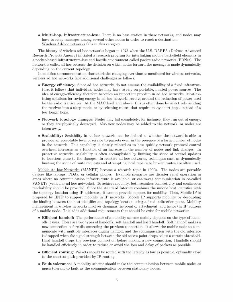
Figure 3 shows a simple example of the first part of Gymkhana protocol, a source node S broadcastsa route request (RREQ) packet across the network to discover all possible paths towards the destinationD (let k be the number of possible paths). The RREQ arriving at D contains two lists:
• The list lak = {IDnk} of the nodes encountered in the path k; each node is identified with its
unique ID
• The list lbk = {Ink } of influence vectors of nodes encountered in the path (the influence vector isa vector of PU activity factors, it equals zero if the SU is not in the coverage area of this PU)
Each secondary node receiving the RREQ, checks if its ID is already contained in la. If this isthe case, the node discards the RREQ to avoid cycles, otherwise it adds its ID in la and its influencevector I in lb and then broadcasts the RREQ.
Processing of the contents of the received RREQs at a destination is done in the second part ofthe algorithm; the goal of this part is to construct a virtual graph representation Vk of the path k interms of nodes composing the paths and PUs affecting these nodes. Np virtual nodes are associated toeach node n of the path k, and between two virtual nodes there exists an edge only if these two nodesare consecutive nodes in the path k or if these two nodes are the virtualizations of the same node ondifferent channels. Two different kinds of edges can be distinguished as follows:
1. The horizontal edge: Horizontal edge between n(p) and n+ 1(p) indicates that node n receivesa packet from channel cp and retransmits the packet over the same channel to node n+ 1
2. The vertical edge: Vertical edge between the virtual nodes n(p) and n(q) indicates that node nswitches from cp to cq
8
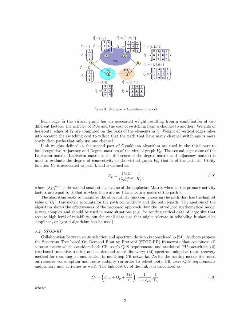
Figure 3: Example of Gymkhana protocol
Each edge in the virtual graph has an associated weight resulting from a combination of twodifferent factors: the activity of PUs and the cost of switching from a channel to another. Weights ofhorizontal edges of Vk are computed on the basis of the elements in lbk. Weight of vertical edges takesinto account the switching cost to reflect that the path that have many channel switchings is morecostly than paths that only use one channel.
Link weights defined in the second part of Gymkhana algorithm are used in the third part tobuild cognitive Adjacency and Degree matrices of the virtual graph Vk. The second eigenvalue of theLaplacian matrix (Laplacian matrix is the difference of the degree matrix and adjacency matrix) isused to evaluate the degree of connectivity of the virtual graph Vk, that is of the path k. Utilityfunction Uk is associated to path k and is defined as:
Uk =(λ2)k
(λ2)cleark
.1
Hk(12)
where (λ2)cleark is the second smallest eigenvalue of the Laplacian Matrix when all the primary activityfactors are equal to 0, that is when there are no PUs affecting nodes of the path k.
The algorithm seeks to maximize the above utility function (choosing the path that has the highestvalue of Uk), this metric accounts for the path connectivity and the path length. The analysis of thealgorithm shows the effectiveness of the proposed approach, but the introduced mathematical modelis very complex and should be used in some situations (e.g: for routing critical data of large size thatrequire high level of reliability, but for small data size that might tolerate in reliability, it should besimplified, or hybrid algorithm can be used).
5.2. STOD-RP
Collaboration between route selection and spectrum decision is considered in [24]. Authors proposethe Spectrum Tree based On Demand Routing Protocol (STOD-RP) framework that combines: (i)a route metric which considers both CR user’s QoS requirements and statistical PUs activities; (ii)tree-based proactive routing and on-demand route discovery; (iii) spectrum-adaptive route recoverymethod for resuming communication in multi-hop CR networks. As for the routing metric it’s basedon resource consumption and route stability (in order to reflect both CR users QoS requirementsandprimary user activities as well). The link cost Ci of the link li is calculated as:
Ci =
(Oca +Op +
Pktri
).
1
1− epti.
1
Tli(13)
where:
9

• Oca, Op and Pkt are constants for specific access technology and represent the channel overhead,protocol overhead and packet size, respectively;
• ri is the link rate (in Mbps);
• epti is the packet error rate on the link;
• Tli is the time duration during which a spectrum band is available to the link li.
The available time of the spectrum band Tli in the metric reflects the integration of the link stabilityto the link quality. Its value can be predicted from the statistical history of PU activities. The cost ofan end-to-end route composed of k links is:
C =
k∑i=1
Ci +M.Dswitching (14)
where:
• M is the number of spectrum band switches along the route;
• Dswitching is the switching delay caused by a CR user switches between two different bands.
CR users form a tree in each available spectrum band, called spectrum-tree. Each spectrum-treehas only one root, which keeps the basic information about the spectrum-tree topology, such as theroutes to other non-root nodes. Nodes belonging to multiple spectrum-trees and having multi-radiosare called ”overlapping” nodes and they can work in multiple spectrum- trees simultaneously. Eachnode has its unique CR use ID (CRID) in one spectrum-tree. The CRID of node X is CRIDx = A0
A1 .. An , where A0 is the spectrum band in which the spectrum-tree is formed, and it’s also the CRIDof the root in this spectrum-tree, n is the hop number away from the root. The overlapping node hasmultiple CRIDs.
A root selection procedure makes sure that there is only one root in each spectrum tree. Thenode which belongs to the largest number of spectrum trees - so it can work in multiple spectrumbands or that has the longest time duration during which a spectrum band is available is selected asthe root. The formulated spectrum-tree is used for both Intra-spectrum routing and Inter-spectrumone. Intra-spectrum routing occurs in a single spectrum-tree, while inter-spectrum routing occurs inmultiple spectrum-trees.
In intra-spectrum routing, when a source node S wants to send data to destination node D andthey are in the same spectrum-tree, node S sends Spectrum Route REQuest (SRREQ) to the rootof its spectrum-tree by using the proactive path, the root checks if node D is in the same spectrum-tree, it adds the CRIDD of node D to the SRREQ, sets a flag in the SRREQ indicating that it’s anintra-routing procedure and sends the SRREQ back to node S. After receiving the message, node Sknows that D is in the same spectrum-tree, so S broadcasts the request to the spectrum-tree as AODVdoes and reactively get the route to D. In the other side, inter-spectrum routing is used if the rootfinds that the destination node D is in another spectrum-tree in respect to S, the root then checks itsinter-spectrum nodes list to find an overlapping node between the two spectrum bands and one of thefollowing two cases will occur:
• The root doesn’t find an overlapping node: it will get the data from node S and send it to nodeD using the proactive links.
• The root finds an overlapping node: it will choose the one which has the shortest queuing sizeand send the SRREQ to this intermediate node. The intermediate node knows from the SRREQthat route between S and D will be established through itself, so it broadcasts SRREQ in firstspectrum-tree - the spectrum-tree that S belongs to - to find the best path to S, and the samein the second spectrum-tree to find the best path to D.
10

STOD-RP also introduces fast and efficient spectrum-adaptive route recovery method, both spec-trum handoff and path rerouting methods are used. When spectral dynamics due to primary userschanges slowly, the system avoids further coordination by using path rerouting at the same frequencybands. In case for instance it’s impossible to use a spectrum band, spectrum handoff is used and allnodes in the spectrum-tree handoff to an available spectrum band.
5.3. Spectrum Aware Highly Reliable Routing in CRNs
Differently from the previous solutions, reliability is achieved in [25] by exploiting the concept ofmulti-path routing. The main design idea behind this protocol is to chose the most stable path amongall candidates and uses it as the primary path, and selects another path that is maximally disjointedwith the primary path called the alternative path, which is used when the primary path fail becauseof PU detection or any other reasons. The used route metric is a combination of channel stability time(CST), link stability time (LST) and switching delay, that’s to select the most stable path.
An independent ON/OFF random process is the usage pattern of PUs which affect channel k usedby a SU, an ON period T kon represents the time that PUs are active in using channel k, and an OFFperiod T koff represents the time that PUs are inactive in using channel k so this channel can be used
by SUs. It’s assumed that T kon and T koff are exponentially distributed with means equal to 1/µk and1/λk seconds respectively. Assuming that the maximum waiting time is Tm (maximum length of ONperiod), so channel k’s stable time is a period before an ON period T kon exceeds Tm, and the expectednumber of ON periods channel k would experience during its stable time can be calculated as follows:
γk =1
P{T kon >= Tm}(15)
, channel k’s stable time is denoted as CST(i j, k) for linkji (i.e., link j in path i) and assuming that it
begins with the OFF period, so the stable time of this channel contains γk OFF periods, γk − 1 ONperiods and a Tm , so it can be expressed as:
CST(j,k)i = γk.E[T koff ] + (γk − 1).E[T kon|T kon < Tm] + Tm
= eµk.Tm(1
λk+
1
µk)− 1
µk
(16)
The protocol then presents an algorithm that selects the ”best” channel from channels, and this channelis used by linkji , the algorithm also calculates Link Stable Time (LST) of the chosen channel to be usedin calculating Path Stable Time (PST) which is the period of time before some link is failed. Supposethere are h hops/links between the source and the destination in path i, PST can be calculated asfollows:
PSTi =1∑h
j=11
LST ji
(17)
, after getting all RREQs from different paths, the destination chooses the path with maximal PathEffective Time (PET) which equals the difference value between PST and the mean of all intermediatenode’s switching delay as the primary path. For the alternative path, it’s chosen to be maximallydisjointed with the primary path, and there are two types of disjoint paths: node-disjoint and link-disjoint. Node disjoint paths don’t have any nodes in common, except the source and destination,while link-disjoint paths don’t have any common link. Both node disjoint degree and link disjointdegree metrics are used to select the alternative path.
This protocol also provides a path maintenance mechanism, it considers a link to be disconnectedor a node failure when a node fails to deliver data packets to next hop of the path, and it sendsa Route Suspend packet to the upstream direction of the path to inform the source to suspend thecurrent session. A Route Error packet is sent back if the disconnected link/node is not recovered aftersome specific time, and when the source receives a Route Error message, it either uses the alternativepath if it’s available, or if it’s not available it initiates a new path discovery process.
11
(a) PuER(L) is the PU effective regionof link L where Pr is the PU transmis-sion range, the area is approximated tothe dotted polygon
(b) Closeness of the two links is thearea of intersection (Hatched Region)
(c) Closeness of the two routes is thearea of intersection (Hatched Region)
Figure 4: Routes closeness definition.
5.4. Routing protocol with Route-closeness metric
As the previous approach, the work in [26] exploits also the concept of multi-path routing foracheiving the reliability but with introducing a new routing metric called ”Routes Closeness”. RoutesCloseness metric selects routes based on how far away they are from each other, the more the routesare far from each other the less PU interruption they face, because a single active mobile PU wouldnot be able to interrupt all of them at the same time, so selecting non-close routes can reduce thenumber of interrupted routes and therefore, connection reliability and throughput are increased.
The authors give a clear definition of the closeness of two routes as the pairwise closeness of theirlinks, the closeness of two routes R1, R2 is:
Closeness(R1, R2) =∑∀Lp∈R1
∑∀Lq∈R2
Closeness(Lp, Lq) (18)
where the closeness of the two links p, q; Closeness(Lp, Lq) is the area of intersection between thePUs effective region of the two links:
Closeness(Lp, Lq) = Area(PuER(Lp) ∩ PuER(Lq)) (19)
The PUs effective region of a link (e.g. PuER(L) )is defined as the region around the link wherea PU is able to interrupt that link, it depends on the PUs transmission range. Figure 4 shows anexample of the PUs effective region, link closeness and routes closeness metric. A PU in the hatchedregions interrupts both links/routes at the same time, but at any other point, the PU interrupts oneof them at most.
For the route discovery phase, a variation of the DSR protocol is used but with some differencesto be suitable for the routes closeness metric, DSR tries to find the shortest path between the sourceand destination, but in the proposed protocol the shortest path is not enough, it tries to find a set ofdifferent routes that span the whole field. For the route selection process, an algorithm for selecting thebest routes among some candidate routes is given in the paper such that the routes closeness betweenthese routes is maximized.
12
6. Throughput Based Approaches
Throughput can be defined as the average rate of successful packet delivery per second. In thissection, we present routing protocols that consider the throughput as the routing metric, and thetarget is to maximize the throughput as possible.
6.1. SAMER
Spectrum Aware Mesh Routing (SAMER) [27] is a routing solution for CORNETs that considersboth long term and short term spectral availability. It balances between long-term optimality (in termsof hop count) and shortest opportunistic gain (in terms of higher spectrum availability). Its main goalis to opportunistically utilize the spectrum in the network, by routing traffic across paths with higherspectrum availability while at the same time it achieves long-term stability by not deviating from theshortest hop-count path.
SAMER builds a forwarding mesh which is adjusted periodically according to the spectrum dynam-ics, and opportunistically routes packets across this mesh. The mesh is centered around the long-termshortest path (in terms of hop count), but opportunistically expands or shrinks periodically to exploitspectrum availability. The protocol associates paths with Path Spectrum Availability (PSA) metrics.Then, packets are delivered opportunistically along the path with the highest PSA value and that isavailable at that point in time. Authors of SAMER define a metric for estimating Path SpectrumAvailability (PSA). PSAs goal is to capture:
1. Local spectrum availability: Spectrum availability at a node i depending on the number of avail-able spectrum blocks at i, their aggregated bandwidth and the contention from secondary users
2. Spectrum blocks quality: which depends on their bandwidth and loss rate.
The PSA is expressed as the throughput between a pair of nodes (i, j) across a spectrum block bas:
Thr(i,j),b = Tf,b.Bw,b.(1− ploss,b) (20)
where Bw,b is the bandwidth and ploss,b the loss probability of the spectrum block b. This lattervalue can be estimated by measuring the loss rate of broadcast packets between pairs of neighboringnodes. In Eq. (14), Tf,b is the minimum between the fractions of time during which the node i is freeto transmit and/or receive packets through a spectrum block b. The aggregate throughput Thr(i,j)between a pair of neighboring nodes is then computed on the basis of the spectrum blocks availableat a node i and then smoothed by multiplying it by a value a (assumed to be 0.4) to capture boththe current view and the statistical information of spectrum availability. The Smoothed AggregateThroughput is then updated as:
SThr(i,j) = α.SThr(i,j) + (1− α).Thr(i,j) (21)
Spectrum availability for a path P is then defined as the minimum Smoothed Aggregate Throughputfor (i, j) belongs to P.
When a node relays a packet, it chooses the next hop based on PSA and local spectral availability.The next hop is chosen locally along the path that has the best PSA value and for which the spectrumis available. Since the channel can be accessed by many SUs, SUs contend for a channel over theCCC. All spectral resource reservations are performed over the CCC before an SU transmits a packet.If SU contention is high, this is reflected in the measurements of bandwidth availability that in turnaffect the PSA values of paths. Consequently, the proposed scheme accounts for SU as well as PUactivity to rank paths. In the paper, SAMER is found to outperform the popular hop count and Ex-pected Transmission Time (ETT) metrics, and this eventually leads to higher end-to-end performance.Furthermore, simulation results suggest that SAMER avoids highly congested and unavailable links.However, overheads associated with forwarding mesh establishment and maintenance have not beenconsidered in depth.
13

6.2. SPEAR
Multi-hop distributed channel assignment and routing algorithm is introduced in [28], it supportshigh-throughput packet transmission; the main idea behind SPEAR is to integrate the end-to-endoptimization of flow-based approaches with the flexibility of link-based approaches to address spectrumheterogeneity. Its contribution mainly include three parts: integration of spectrum discovery and routediscovery to cope with spectrum heterogeneity; coordination of channel assignment of a per-flow basis,by minimizing inter-flow interference; exploiting local spectrum heterogeneity and assigning differentchannels to links on the same flow to minimize intra-flow interference.
Route discovery phases starts when a node need to send data, it broadcasts AODV-style routediscovery message to its neighbors which accumulates information about each node’s available channelsand their quality, but unlike AODV, SPEAR allows multiple paths to propagate to the destination forselecting the best path. To account for inter and intra flow interference, nodes intersecting differentflows store the time schedules of these flows, these parameters are combined and used by the destinationto select the optimal route which is then reserved by using RREP message.
6.3. CRP
Another approach that aims to maximize the throughput is introduced in [29], it’s a distributedrouting protocol that combines several key CR-specific performance metrics to maximize bandwidthavailability and to provide explicit protection to PU receivers, the metrics that are considered duringthe route setup stage are (1) probability of bandwidth availability, (2) variance in the number ofbits sent over the link, (3) spectrum propagation characteristics, (4) PU receiver protection, and (5)spectrum sensing consideration, so it’s one of the few examples that consider this large number ofmetrics in one technique. It also considers two routing classes; class1 provides higher significance toCR performance while meeting minimum PU interference avoidance; class2 prioritizes PU protectionover achieving low end-to-end latency for CR users.
In CRP, the route setup follows two stages. In the first stage (spectrum selection stage), eachCR user identifies the best spectrum band and the preferred channels within that band, this is doneusing many unique CR metrics that were mentioned before- which are weighted appropriately in anoptimization framework for choosing the spectrum. An optimization function is developed for each classof CR route, which also serves as a measure of the initiative displayed by the CR user for participatingin the route. In the second stage (next hop selection stage), the candidate CR users rank themselvesdepending on the choice of the spectrum, and the local network and physical conditions, these ranksdetermine which CR users take the initiative in the subsequent route information, this initiative ismapped to a delay function for forwarding the RREQ message, so the preferred users broadcast theRREQ earlier. The destination chooses the final route that best meets the goals of the desired routingclass by a route reply (RREP).
Route maintenance is provided in CRP, it has a proactive and a reactive component, the authorsassume that the network architecture is composed of stationary PU transmitters with known locationsand maximum coverage ranges, as in the case for television broadcast towers. The CR users are mobile,location-aware, and have no knowledge of the PU receivers. During proactive maintenance, each CRuser continuously monitors its own location with respect to the known PU transmitter locations, andwhen a CR node moves toward one or more PUs, it proactively discover a new path in case the currentroute fails.
7. Location Based Approaches
Many of today’s wireless devices are location enabled, and it’s expected to spread widely in thenext few decades. This motivates the work in location-based metrics for CRNs specially when locationinformation of CR nodes can be easily obtained via FCC Geolocation-Databases [2]. Although location-based routing has already been investigated generally for ad hoc networks, using it in CRNs will facemany different and new challenges such as the dynamic changes in network connectivity due to the
14
frequent changes in the spectrum opportunity of the CR nodes due to PU activity, another issue alsois to make the routing protocol aware of this dynamic changes and to jointly select the route and thechannel that will be used in the routing process. This section overviews proposed routing protocolsthat use location-based metric for constructing the routes.
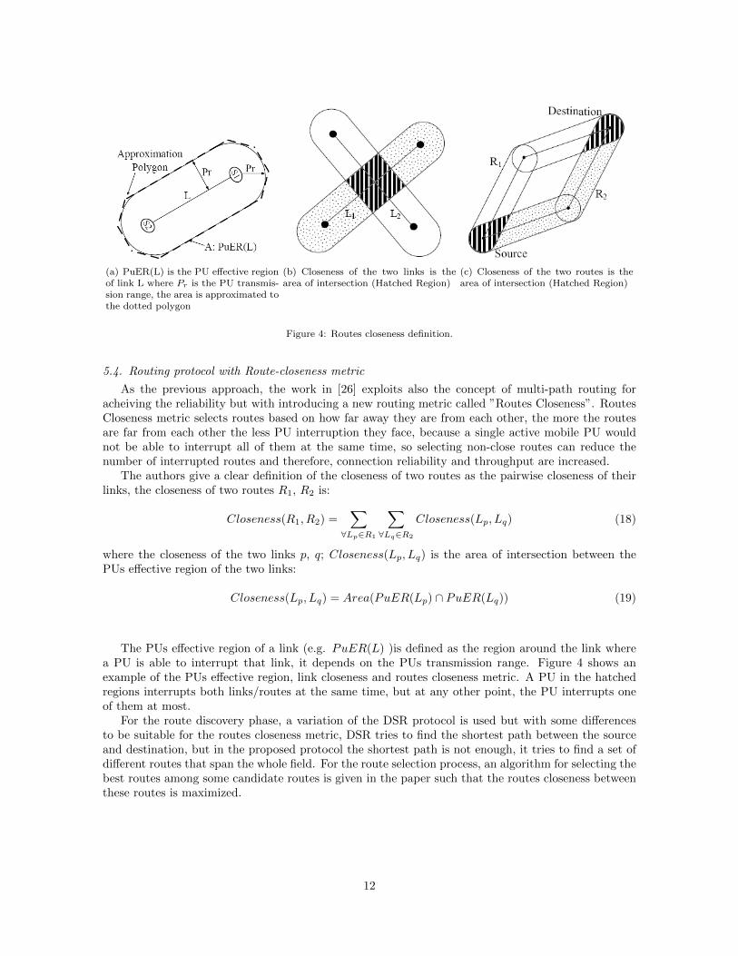
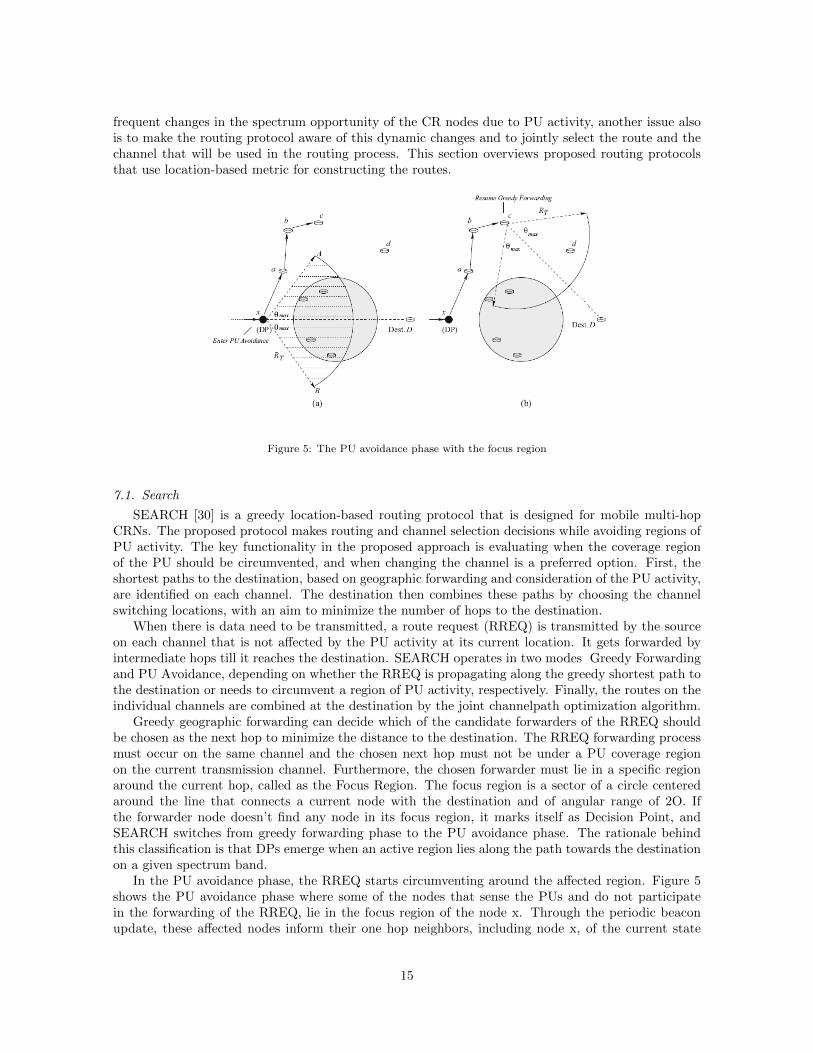
Figure 5: The PU avoidance phase with the focus region
7.1. Search
SEARCH [30] is a greedy location-based routing protocol that is designed for mobile multi-hopCRNs. The proposed protocol makes routing and channel selection decisions while avoiding regions ofPU activity. The key functionality in the proposed approach is evaluating when the coverage regionof the PU should be circumvented, and when changing the channel is a preferred option. First, theshortest paths to the destination, based on geographic forwarding and consideration of the PU activity,are identified on each channel. The destination then combines these paths by choosing the channelswitching locations, with an aim to minimize the number of hops to the destination.
When there is data need to be transmitted, a route request (RREQ) is transmitted by the sourceon each channel that is not affected by the PU activity at its current location. It gets forwarded byintermediate hops till it reaches the destination. SEARCH operates in two modes Greedy Forwardingand PU Avoidance, depending on whether the RREQ is propagating along the greedy shortest path tothe destination or needs to circumvent a region of PU activity, respectively. Finally, the routes on theindividual channels are combined at the destination by the joint channelpath optimization algorithm.
Greedy geographic forwarding can decide which of the candidate forwarders of the RREQ shouldbe chosen as the next hop to minimize the distance to the destination. The RREQ forwarding processmust occur on the same channel and the chosen next hop must not be under a PU coverage regionon the current transmission channel. Furthermore, the chosen forwarder must lie in a specific regionaround the current hop, called as the Focus Region. The focus region is a sector of a circle centeredaround the line that connects a current node with the destination and of angular range of 2O. Ifthe forwarder node doesn’t find any node in its focus region, it marks itself as Decision Point, andSEARCH switches from greedy forwarding phase to the PU avoidance phase. The rationale behindthis classification is that DPs emerge when an active region lies along the path towards the destinationon a given spectrum band.
In the PU avoidance phase, the RREQ starts circumventing around the affected region. Figure 5shows the PU avoidance phase where some of the nodes that sense the PUs and do not participatein the forwarding of the RREQ, lie in the focus region of the node x. Through the periodic beaconupdate, these affected nodes inform their one hop neighbors, including node x, of the current state
15
of the channel environment. Thus, node x is aware that the closest node to the destination that canforward the RREQ (node a) lies outside its focus region. Node x concludes that it is a DP and setsthe PU avoidance (PA) flag in the RREQ packet before retransmitting it. The PA flag in the RREQremains set till a node is reached that has a candidate forwarder in its focus region. The RREQtraverses the node a; b and finally reaches node c. The latter has a candidate forwarder (node d) ,that lies in its focus region. At this point, i.e., at node d, the PA flag is reset, signaling the end of theavoidance phase and the greedy forwarding is resumed. Once the RREQ packets forwarded in differentchannels reach the destination, the destination node makes a path and channel selection decision toform the end-to-end path. The selection of the end-to-end path is based on the shortest path amongall candidate paths discovered over different channels.
7.2. LAUNCH
LAUNCH [31] is a location-based routing protocol which uses location information to guide theroute discovery process, different from SEARCH protocol, LAUNCH takes into consideration thestochastic activity of the PUs to select the most stable routes. Furthermore, it doesn’t only handle thePUs when they are active, but also selects routes that are expected to be more stable, it prefers long-lived routes over short-lived ones. LAUNCH makes greedy decision to select the next hop neighborthat satisfies the following conditions:
• It’s closer to the destination (guaranteeing that we are always getting closer to the destination).
• It has the minimum expected delay.
The delay metric estimates the delay between any two nodes as follows:
T =Tprop + Tswitch
1− Pactive(22)
where Tprop is the propagation time between the two nodes, Tswitch is the channel switching timeand Pactive is the probability that at least one PU that affects the link between the source and thedestination will become active during some predefined time.
LAUNCH is more simple than SEARCH and doesn’t have all the details presented in SEARCH,but it gives a good performance evaluation analysis by studying the impact of changing SUs density,number of PUs, PUs heterogeneity, SUs mobility, data rate and number of channels.
8. Discussion and Open Research Issues
Routing in multi-hop CRNs is challenging compared to traditional wireless multi-channel multi-hopnetworks due to the dynamic behavior of PUs and their effect on changing SOP of SUs, and the bigneed of joining routing decision with spectrum selection process. In this paper we have summarizedrecent routing protocols in CRNs that are based on local spectrum knowledge, they are classifiedaccording to the routing metric to delay-based, link stability based, throughput-based and locationbased approaches. In some cases the protocols are able to set up the whole path with source routingwhile in other cases the proposed approaches are based on hop by hop selection of next node. There aresome common characteristics between all routing approaches that are summarized in this survey; thefirst characteristic is that they combine spectrum selection to the routing on each link of the path, thesecond one is the protection of PUs as it’s an important key parameter to be considered in multi-hopCRNs, each solution provides a measure of protection to the ongoing communication of the PUs, butonly few number of them have the ability to reconfigure the path when a PU becomes active. We alsoobserved that only few solutions have considered the true cross-layering approach, and the mobilityof SUs is not supported by the majority of them. As a conclusion of this survey, open research issuesand routing-related areas that need more contribution are discussed in the following subsections.
16

8.1. True Cross Layering
Cross-layer design is an attractive new approach to improve the performance of wireless systems.This is particularly important in the CR networks where spectrum sensing information is required tobe exchanged among multiple layers (requires cooperation of PHY and MAC layers to get spectrumsensing information that is consumed by routing layer).
There are two basic cross-layer design approaches as identified in [32]: implicit cross-layer design andexplicit cross-layer design. With implicit cross-layer design there is no explicit violation of the referencelayered architecture but during the design phase all layer interactions are taken into considerationto perform a joint protocol optimization, most of the CR routing protocols use this approach forspectrum sensing information exchange, where information produced by lower layers (PHY, MAC) isconsumed by higher layers (Network layer) and no direct feedback is provided back to the lower layersas reported in [14]. On the contrary, explicit cross-layer design which is called ”True cross-layering”allows direct bi-directional communication between non-adjacent layers, in addition to the ability ofmerging and/or splitting of layers. Applying true cross-layering can improve the performance of thenetwork dramatically, it can also improve many functions like SU mobility management, selectingend-to-end candidate path and channel allocation decisions.
8.2. Mobility Support
As the explosion of Internet portable devices continues, applications and services needed to supportmobility should have different network requirements. The authors of [33] study the impact of nodemobility on MANET routing protocols and introduces four mobility models: (1) Random waypoint;which is the most commonly used mobility model in research community in which a node randomlychooses a destination and moves toward it with a velocity chosen randomly from a uniform distribution.(2) Random Point Group Mobility (RPGM); which can be used in military battlefield communication,there is a group leader that determines the group’s motion behavior. (3) Freeway Mobility Model;which emulates the motion behavior of mobile nodes on a freeway, It can be used in exchanging trafficstatus or tracking a vehicle on a freeway. (4) Manhattan Mobility Model; it emulates the movementpattern of mobile nodes on streets defined by maps. Similar mobility models should be applied andstudied for CRNs, but this is much harder to be handled there because it has to manage not onlychanges in the SUs physical location but possibly changes in the SUs operation frequency due to PUactivity in the new location. As reported in Table 1, only few solutions have considered till now the SUsmobility and most of them address CRNs with static topology, so it still needs major contributions.
8.3. Path Robustness (multiple routes)
For emergency applications, nodes can’t lose the connection during transmission for any reason.For example, if there is an emergency in a chemical factory, each worker must be advised immediatelyabout leakages through a network capable of multicasting information reliably, so introducing multipleroutes in such case is very important. In [34], simple analysis is done to study the impact of multipleroutes on routing protocol robustness, and it’s observed that one additional route to the path betweennodes increases reliability by certain extent and strongly decreases failure probability. Only a fewnumber of routing protocols for CRNs considers the issue of multiple routes, and the majority of themare based on the idea of using two disjoint paths, primary path and alternative path to achieve highlyreliable routing, the alternative path is utilized only when data packets are not deliverable through theprimary path. A generalization of this consideration leads us to the use of many routes (not only tworoutes) according to the level of reliability that is required by the CR network, and all of them shouldbe disjoint as possible and not close to each other, because selecting non-close routes makes them lessvulnerable to PUs’ activities at the same time.
8.4. Quality of Service (QoS)
Quality of Service is the ability to provide different priority to different applications, users, or dataflows, or to guarantee a certain level of performance to a data flow [35]. Resource constraints such as
17

spectrum bandwidth and dynamic network conditions over time due to interference with PUs increasethe requirement of a proper QoS for the various applications that use the CRNs, and especially forreal-time multimedia applications, since they are delay sensitive and the capacity is a limited resourcein CRNs. A survey on QoS provisioning for multimedia transmission over CRNs [35] lists the reasonsfor the need of a proper QoS system over cognitive radio as follows:
• Spectrum bandwidth constraints and dynamical changing of network topology.
• For video transmission, loss of certain important frames may degrade the video quality for thereceiver significantly.
• Delay generated from sensing and channel switching activities may cause some video frames tomiss the deadline.
• Upon arrival of PUs, SUs with multimedia traffic may be affected more than those with typicaldata traffic.
References
[1] M. McHenry, “Spectrum white space measurements,” presentation to New America FoundationBroadBand Forum, 2003.
[2] F. C. Commission, “Fcc adopted rules for unlicensed use of television white spaces. tech. rep. etdocket no. 04-186, second report and order and memorandum opinion and order,” 2004.
[3] I. Akyildiz, W.-Y. Lee, M. Vuran, and S. Mohanty, “Next generation/dynamic spectrum ac-cess/cognitive radio wireless networks: a survey,” Computer Networks, pp. 2127–2159, 2006.
[4] I. Akyildiz, W.-Y. Lee, and K. Chowdhury, “Crahns: cognitive radio ad hoc networks,” Ad HocNetworks, pp. 810–836, 2009.
[5] J. Ma, G. Li, and B. Juang, “Signal processing in cognitive radio,” Proceedings of the IEEE, pp.805–823, 2009.
[6] T. Yucek and H. Arslan, “A survey of spectrum sensing algorithms for cognitive radio applica-tions.”
[7] I. F. Akyildiz, B. F. Lo, and R. Balakrishnan, “Cooperative spectrum sensing in cognitive radionetworks: A survey,” Physical Communication (Elsevier), pp. 40–62, 2011.
[8] L. Cao and H. Zheng, “Distributed spectrum allocation via local bargaining,” IEEE Sensor andAd Hoc Communications and Networks (SECON), pp. 475–486, 2005.
[9] J. Huang, R. Berry, and M. Honig, “Spectrum sharing with distributed interference compensa-tion,” IEEE DySPAN, pp. 88–93, 2008.
[10] L. Ma, X. Han, and C. Shen, “Dynamic open spectrum sharing mac protocol for wireless ad hocnetwork,” IEEE DySPAN, pp. 203–213, 2005.
[11] S. Sankaranarayanan, P. Papadimitratos, A. Mishra, and S.Hershey, “A bandwidth sharing ap-proach to improve licensed spectrum utilization,” IEEE DySPAN, pp. 279–288, 2005.
[12] J. Zhao, H. Zheng, and G.-H. Yang, “Distributed coordination in dynamic spectrum allocationnetworks,” IEEE DySPAN, pp. 259–268, 2005.
18

[13] Q. Zhao, L. Tong, and A. Swami, “Decentralized cognitive mac for dynamic spectrum access,”IEEE DySPAN, pp. 224–232, 2005.
[14] M. Cesana, F. Cuomo, and E. Ekici, “Routing in cognitive radio networks: Challenges and solu-tions,” Elsevier Ad Hoc Networks, 2010.
[15] G. Cheng, W. Liu, Y. Li, and W. Cheng, “Spectrum aware on-demand routing in cognitive radionetworks,” 2nd IEEE International Symposium on New Frontiers in Dynamic Spectrum AccessNetworks, pp. 571–574, 2007.
[16] G. Cheng, W. Liu, and Y. Li, “Joint on-demand routing and spectrum assignment in cognitiveradio networks,” IEEE International Conference on Communications, pp. 6499–6503, 2007.
[17] Z. Yang, G. Cheng, W. Liu, W. Yuan, and W. Cheng, “Local coordination based routing andspectrum assignment in multi-hop cognitive radio networks,” Mobile Networks and Applications,pp. 67–81, 2008.
[18] Z. Song, B. Shen, Z. Zhou, and K. S. Kwak, “Improved ant routing algorithm in cognitive radionetworks,” Communications and Information Technology, ISCIT 9th International Symposium,2009.
[19] M. Dorigo, G. D. Caro, and L. M. Gambardella, “Ant algorithms for discrete optimization,” Artif.Life, pp. 137–172, 1999.
[20] J. L. Deneubourg, S. Aron, S. Goss, and J. M. Pasteels, “The self-organizing exploratory patternof the argentine ant,” Journal of Insect Behavior, pp. 159–168, 1990.
[21] B. E., D. M., and T. G., “Swarm intelligence: from natural to artificial systems,” Oxford UniversityPress, 1990.
[22] K. M. A., E.-S. R. J., and M. I. P., “Swarm intelligence for routing in communication networks,”IEEE Globecom, 2001.
[23] A. Abbagnale and F. Cuomo, “Gymkhana: a connectivity-based routing scheme for cognitiveradio ad hoc networks,” IEEE Conference on Computer Communications, INFOCOM, pp. 1–5,2010.
[24] G. Zhu, I. Akyildiz, and G. Kuo, “Stod-rp: a spectrum-tree based on demand routing protocol formulti-hop cognitive radio networks,” IEEE Global Telecommunications Conference, GLOBECOM,pp. 1–5, 2008.
[25] H. Song and X. Lin, “Spectrum aware highly reliable routing in multihop cognitive radio net-works,” IEEE Wireless Communications and Signal Processing, 2009.
[26] I. Beltagy, M. Youssef, and M. El-Derini, “A new routing metric and protocol for multipath routingin cognitive networks,” IEEE Wireless Communication and Networking Confenrence (WCNC),2011.
[27] I. Pefkianakis and S. L. S. Wong, “Samer: spectrum aware mesh routing in cognitive radio net-works,” 3rd IEEE Symposium on New Frontiers in Dynamic Spectrum Access Networks, DySPAN,pp. 1–5, 2008.
[28] A. Sampath, L. Yang, L. Cao, H. Zheng, and B. Zhao, “High throughput spectrum-aware rout-ing for cognitive radio based ad hoc networks,” Proceedings of the International Conference onCognitive Radio Oriented Wireless Networks and Communications (CROWNCOM), 2008.
[29] K. Chowdhury and I. Akyildiz, “Crp: a routing protocol for cognitive radio ad hoc networks,”IEEE Journal of Selected Areas in Communications (JSAC), 2011.
19
[30] K. Chowdhury and M. Felice, “Search: a routing protocol for mobile cognitive radio ad-hocnetworks,” Computer Communications, pp. 1983–1997, 2009.
[31] K. Habak, M. Abdelatif, H. Hagrass, K. Rizc, and M. Youssef, “A location-aided routing protocolfor cognitive radio networks,” ICNC, 2013.
[32] G. Giambene and S. Kota, “Cross-layer protocol optimization for satellite communication net-works: a survey,” International Journal of Satellite Communications and Networking, 2006.
[33] F. Bai, N. Sadagopan, and A. Helmy, “The important framework for analyzing the impact ofmobility on performance of routing for ad hoc networks,” Ad Hoc Networks - Elsevier Science,pp. 383–403, 2003.
[34] P. Paweczak, “Protocol requirements for cognitive radio networks,” TU Delft, AAF Deliverable,2005.
[35] A. Sivanantha, S. Ehsan, A. Dhamodaran, and K. Gatimu, “A survey on quality of service (qos)provisioning for multimedia transmission in cognitive radio networks.”
20