surveillance quality control understand how the well...
TRANSCRIPT

Job Application Details
• Surveillance
• Quality Control
• Understand How the Well Flows
• Risks understood
• Contingencies, warning flags, when to stop
• When is it over?
www.GEKEngineering.com 1

Acid Job Inspections: pre-job • ____ is the surveillance data sufficient? (job need, application, contingencies?) • ____ daylight adequate for job or clearance and equipment to pump at night? • ____ acid type, strength, volumes, and corrosion inhibitor verified? • ____ inj rate or max pressure limits understood? • ____ iron control additive suitable for job and expected iron content? • ___ mutual solvent or NE agent? Don't use both unless need is demonstrated. • ____ other additive need verified and are additives compatible? • ____ and can all additives plus corrosion inhibitor be effectively mixed? • ____ preflush volume, type, placement and procedure verified? • ____ overflush volume, type and procedure? • ____ tubing cleanout (pickle) procedure specified? • ____ is acid heating required to control tubing contraction or acid freezing? • ____ load fluid recovery aid? (nitrogen, CO2, swab, etc)? • ____ tool requirements (packers, spot valves, wash tools)? • ____ are seals compatible with all fluids, including solvent and flow back? • ____ diverter type and method of removal? • ____ shut-in time estimated (minimum or maximum)? • ____ environmental considerations, handling and disposal restrictions addressed? • ____ when is the flow back over? What data is needed?
www.GEKEngineering.com 2

Acid Job Inspections: loading yard • ____ does batch analysis of acid meet specifications?
– Strength with 2% of call out strength? - titrate for strength.
– HF contamination less than 100 ppm in HCl (for limestone & limey ss) Chlorinated hydrocarbon content less than 100 ppm.
– SO4 content < 1500 ppm and Sulfite (SO3) content less than 100 ppm.
– Total dissolved solids less than 15 ppm & total dissolved iron < 100 ppm.
• ____ live and spent acid compatibility check w/ field formation fluids
• ____ additives MSDS sheets avail. & safety needs known & discussed?
• ____ acid additives on approved list and checked for compatibility?
• ____ transfer lines, pumps, storage tanks and hauling trucks clean?
• ____ additives added (volu checked by meter or calibrated measure).
• ____ fresh water makeup for HCl/HF is compatible with HF.
• ____ capability to circulate tank?
• ____ additive batch numbers necessary?
www.GEKEngineering.com 3

Acid Job Inspections: field • ____ tanks rolled continuously prior to injection? • ____ HCl acid strength by titration or hydrometer? • ____ raw acid color checked? (yellow/green indicates iron.) If inhibitor added,
no color test possible. • ____ no visible solids suspended in acid. (Filter if needed using polypropylene
filter elements or DE with polish PP filter.) • ____ obtain copy of loading ticket - this ticket must be on truck to satisfy hazardous
materials transport law. • ____ check size of ball sealers and compare to perforation size (balls must be at
least 0.25” larger than largest perforation diameters. • ____ check density of ball sealers (use fresh water as a check) if used. • ____ check number of balls and schedule for dropping. • ____ verify diverter particle size if used. • ____ correct type and volume of additives available? • ____ correct type and quantity iron control? • ____ are field compatibility tests needed? • ____ are tanks, pumps and lines clean? • ____ all recording devices on location and working correctly?
www.GEKEngineering.com 4

Acid Inspections: Job • ___ Safety meeting with responsibilities set out clearly.
• ____ saw pressure decrease when acid reached formation?
• ____ saw pressure response of diverter/balls.
• ____ pressure recording during job?
• ____ ISIP at 5, 10, 15 min.
• ____ estimate of initial backflow rate (BPM) if flowing.
• ____ acid strength of backflow by titration. (Hydrometer won't work here.)
• ____ sample of spent acid collected for iron analysis, if required?
• ____ are there emulsions in backflow? Do they break quickly (<5 min)?
• ____ presence of solids in backflow.
• ____ presence of highly concentrated inhibitor in backflow. Concentrated inhibitor signifies that acid and inhibitor were not well mixed before pumping.
www.GEKEngineering.com 5

Temperatures in the Well? Circulating or High Rate Injection?
0
2000
4000
6000
8000
10000
12000
14000
16000
18000
30 40 50 60 70 80 90 100 110 120 130
Tubing
Tbg Fluid
Casing 1
Undisturbed
Circulation pump rate = 8-BPM
BHST= 122*F
BHCT= 98*F
0
2000
4000
6000
8000
10000
12000
14000
16000
18000
30 40 50 60 70 80 90 100 110 120 130
Undisturbed
Tbg Fluid
Tubing
Casing 1
Frac job pump rate = 35-BPM
BHST= 125*F
BHTT= 86*F
www.GEKEngineering.com 6

Considerations for Fluid loss Control Selection
BHT Formation sensitivity to treatment fluids
Onshore / Offshore / Deepwater
BHP Treatment/completion fluid types Rig cost per day
Overbalance or underbalance Frequency and amount of surge/swab loads
Rig equip available -pumps, tanks, lines,
Vertical and horizontal permeability variations
Formation sand strength All tubular sizes in the flow path
Formation sand size and pore throat size
Sand production and presence of cavity
Mobilization time available
Production rate Producer or injector Regulations on use and disposal
Produced fluid types Wellbore deviation through the pay Natural or hydraulic fractures present
SPE 54323
www.GEKEngineering.com 7
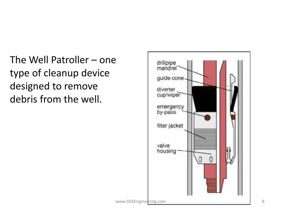
Debris cleanup in the tubulars
The Well Patroller – one type of cleanup device designed to remove debris from the well.
www.GEKEngineering.com 8

Learning • Functioning the BOP with a clean fluid in the
well can introduce junk
• Mixing water, brines, and particularly acid with OBM without suitable surfactants/solvents creates “insoluble” gunk (very viscous sludge) that prevented packers being set
www.GEKEngineering.com 9

Cleanout and Debris Management Best Practices
• Proper preparation of tubulars to eliminate rust and mill scale – clean prior to use.
• Careful fluid and hydraulic design to ensure effective hole cleaning and fluid compatibility
• The cleanliness of the wellbore should be confirmed by a gauge ring or drift sub using the clean up/workover string.
• Where there is concern about tubular condition (rust/mill scale/excessive doping/cement) pipe pickling should be considered.
www.GEKEngineering.com 10

Acid Corrosion Inhibitor
• Work well BUT,
– their efficiency is time, acid strength temperature, and metal surface dependent.
– are not soluble in acid! - will separate!
• separates to top in 30 minutes
• needs vigorous mixing to disperse - gentle circulation will not work.
www.GEKEngineering.com 11

Acid Inhibitor Mixing
• Set up for “rolling” the tank, not slow circulation - upper layer must be mixed in
This Won’t Work!
pump
Unless you
get the top
level caught
in the
circulation
www.GEKEngineering.com 12

Job Application Details
• Surveillance
• Quality Control
• Understand How the Well Flows
• Risks understood
• Contingencies, warning flags, when to stop
• When is it over?
www.GEKEngineering.com 13

Perforating Information - 1 • ____ interval and depth to be perforated?
• ____ type (DP or BH) and size of charge specified?
• ____ temperature rated charge required?
• ____ gun/seals rated for hostile environment? Confirm pressure rating of gun systems (expendables and HSC).
• ____ depth control method (and tolerance) specified?
• ____ logging tools identified?
• ____ size and type of gun/carrier specified. Confirm maximum gun size after firing.
• ____ phasing specified.
• ____ shot density.
• ____ TCP or wireline.
www.GEKEngineering.com 14

Perforating Information - 2 • ____ flow rate or surge time or volume to clean perfs. (1/8 bbl/perf
positive flow is min. recommended flow vol.) Best flow rate is as fast as possible. (Regulations may prevent backflow to surface).
• ____ which log is being tied into?
• ____ date of log being tied into?
• ____ perforating company.
• ____ charge manufacturer and charge id number or size.
• ____ will a full lubricator be needed (what pressures?), field pressure test required at what pressure?
• ____ hole displaced to filtered fluid?
• ____ casing scraper run while displacing fluid?
• ____ casing sub depth known? (are expected).
• ____ hole restrictions, older perforations, drill-out bridge plugs, etc.
www.GEKEngineering.com 15

TCP Inspection • ____ type of firing system (bar drop, pressure, elect. line, etc.) • ____ depth control proc. OK? (correlation log specified). • ____ surface press to fire if press activated. • ____ type of backup firing system? • ____ underbalance specified by press. and hydrostatic? • ____ RA marking of top and bottom shot if gun to be dropped? • ____ Gun release (if gun to be dropped). • ____ type and timing of release? What is the indicator of release? • ____ tool requirements? • ____ after firing gun size OK for retrieval through well restrictions? • ____ circulation vent. • ____ was a RA pip tag placed in the casing to help with depth control? • ____ 100 hour charge life at BHT? • ____ log rerun after tubing spaced and well head flanged?
www.GEKEngineering.com 16

Wireline Conveyed Perforation
• ____ gauge ring run?
• ____ overbalance considered (if casing gun run by wireline).
• ____ underbalance for TT guns? UB in terms of fluid head?
• ____ has dynamic underbalance been modeled for this well?
• ____ lubricator length and id?
• ____ H2S protected wireline needed?
• ____ 24 hr min. charge life at BHT?
• ____ sinker bars needed to enter well?
• ____ can gun be run to depth if well is deviated?
www.GEKEngineering.com 17

Pre-Firing Inspection
• ___ correct phasing and spf? Correct gun body (size, weight & length?) • ___ pressure rating on gun within specification for the well? • ____ new seals on gun-to-gun connectors (tandems)? • ____ no paint or deposits? • ____ make, Q/C and charge part number data available? • ____ date of manufacture of charge. • ____ were the charges sealed in a moisture proof package. If not sealed,
charges older than 3 years in a dry climate and 6 months in a moist climate should not be used.
• ____ DP charges are preferred to have powdered metal liners. • ____ BH charges usually have drawn metal liners. • ____ no cracks, chips, corrosion or scratches on liner. • ____ correct alignment strip carrier for charge. • ____ position screws/pins used.
www.GEKEngineering.com 18

Big Hole charges in a loading tube prior to loading in a scalloped hollow carrier gun. Note
the loading tube holding the big hole charges and the detonation cord at the end of the
tube. The scallop gun, into which the loading tube will be inserted, is at upper left. Pins
and slots are present in the gun to align the charges to the scallops.
The perforating loading process
www.GEKEngineering.com 19

Cap and Cord Information
• ____ explosive grain rating of cord.
• ____ correct type of detonating cord for charge.
• ____ date of manufacturer of detonating cord. (< than 1 year old. )
• ____ a resistor, fluid desensitized cap or safe detonating system must be used on wireline guns.
• ____ part number or name of cap.
• ____ a booster cap must be used at gun joints when joining guns. confirm reliable explosion transfer mechanism.)
• ____ cap at bottom of most E-line fired guns.
www.GEKEngineering.com 20

Safety and BHA Documentation • ____ Safety meeting with responsibilities set out clearly. • ____ check CCL operation with steel bar. Before connection to gun. • ____ sketch of gun showing distance from CCL to top and bottom
shot. • ____ Record size and shape of fishing neck. • ____ Record maximum size of gun/equipment. • ____ radios off. (avoid operation near transmission lines, microwave
towers). Welding equipment off. • ____ ground strap to wellhead. Monitor stray voltages. What are limits
on stray voltages? • ____ safety device on unit in safe position before arming gun. • ____ non critical personnel clear area before cap is installed. • ____ electrical blasting cap connection to be made before connection
of cap to detonating cord. (Not witnessed, only service company to confirm.)
www.GEKEngineering.com 21

Stray Power – suggestions to proceed
• RF, static, impressed current, cathode protection, any source that grounds to the well.
• Electrical grounding straps must be installed between the unit, wellhead, well house, work van, crane or mast truck. Voltages, both AC and DC, between equipment and wellhead must be checked before and after installing grounding straps.
• The following rules (Alaska Well Handbook) apply: • a) Prior to grounding - max. voltage allowable = 2,000 m volts, if greater, solve
voltage problem before continuing • b) After grounding - max. voltage allowable = 200 m volts • Check voltage meters, continuously throughout job to check for electrical
integrity with the rig voltage monitor in prominent display. • Suspend all operations and clear area if lightening is seen or thunder is heard. • Note: the operating company may have specific limits for their equipment or
for an application. These values should be known before the job.
www.GEKEngineering.com 22

Field Loading or arming of perf guns
• Only service company personnel to be involved with either loading or arming of guns or handling of explosives.
• Non service company personnel to be at least 150 ft away and preferably behind a barricade.
• Check that the service company is using the safety switch to short out the unit end of the E-line as any stray current will be taken across the 5000 ohm resistor and not across the detonating cap.
• The key to the safety switch in the E-line unit is to be with the operator stabbing the gun, until the gun is 100 feet in the well. The operator must remove the key when working on any gun, especially missed fired gun, at the surface.
www.GEKEngineering.com 23

Terms
• Electrical arming : means electrically connecting the detonator to the E-line.
• Ballistic arming : means connecting the armed detonator to the rest of the explosive system, e.g., the primer cord and shaped charges, such that initiation of the detonator would cause initiation of the rest of the system.
• No gun shall be armed ahead of time. A gun will ONLY be armed just prior to RIH at the jobsite. Subsequent gun runs will be armed only after being attached to the E-line head.
Alaska Wells Safety Handbook www.GEKEngineering.com 24

Depth Control • ____ depth control reliability known?
• ____ is measurement wheel calibration control accurate?
• ____ record distance from CCL/GR to first shot?
• ____ correction of open hole GR to cased hole GR and/or collars?
• ____ adjust depths for kelly bushing?
• ____ log correlation adequate? RA tag found?
• ____ review depth control procedure?
• ____ cable creep considered?
• ____ RA tagged charges at top, middle and bottom of long gun or if gun is to be dropped?
• ____ log back over perfs to confirm depth?
www.GEKEngineering.com 25

Perforating Inspection – After Firing
• ____ CCL check of perforated interval? (RA check if charges were RA tagged)
• ____ service company checks gun for complete firing and trapped pressure.
• ____ debris in gun is pea to 1 cm size or scraps of alignment equip. (no whole charge cases).
• ____ exit holes in gun are within the scallop.
• ____ holes are round (</= 10% oval, where ovality = [(max-min)/max]
• ____ number / location bad shots recorded. Oval holes photographed?
• ____ confirm CCL depth offsets.
• ____ note location of bad shots.
• ____ If a series of bad shots (more than 10% of total) is found - is reperforating necessary?
www.GEKEngineering.com 26

A 60 degree phased, hollow
steel carrier perforating gun
(scalloped) after firing. Note
the location of the holes in the
scallops and the roundness of
the holes. The purpose of the
scallops is primarily for
containing the burr around the
exit hole and preventing scoring
in polished bores in packers and
profiles. The scallops also
reduce the thickness of the gun
body through which the charge
must penetrate.
After firing gun inspections
www.GEKEngineering.com 27
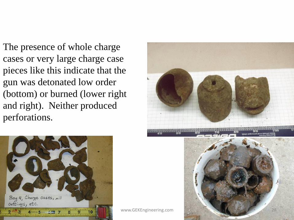
The presence of whole charge
cases or very large charge case
pieces like this indicate that the
gun was detonated low order
(bottom) or burned (lower right
and right). Neither produced
perforations.
Perforating Firing Problems
www.GEKEngineering.com 28

Perf Gun – Inspection Tree
Service
Company
Inspects Gun
All gun fired? / Holes
in the gun?
Measure temperature
of the gun surface.
No
Do not move gun.
Clear area and
wait 15 minutes to
recheck.
T>212F/100C
Gun hole Inspection
Yes
T>212F/100C
Do not move gun.
Clear area and
wait 2 hours to
recheck.
T>212F/100C
Do not move gun.
Service Company
to implement
approved
disposal plan.
T<212F/100C
Service Provider
checks that power
panel is off, then
diagnoses failure.
Partial Fire
Round or Oval Alignment
Equipment
Issue or
impact
In scallop? Missed the scallop?
Go to gun
debris
inspection
Round
Oval
Ovality>10% No
Potential charge
manufacturing
problem
Yes
cool
cool
www.GEKEngineering.com 29

Perforating Problems - 1 Failure Type Causes (may be more than one) Freq.
Estimate Prevention options
Failure to set packer (TCP) Same as conventional pkr set failures
Rare Caliper and scraper runs improve success of setting
Failure to test wellhead seal Same as conv. Rare – 1 in 200+
Failure to initiate gun – bar drop
Debris over firing head 5% in 1994 Circ. port above head, min. dope, second firing head
Failure to initiate gun – pressure fire
blocked press port. applied press too low, wrong components
Up to 10% Use design that allows firing head to be placed after gun is run.
Failure to initiate E-line gun Wire or head conduction problem, cap failure
2% miss run rate
www.GEKEngineering.com 30

Perforating Problems - 2 Failure Type Causes (may be more than one) Freq. Estimate Prevention options
Failure to fire entire gun length
Cord/booster failure, pinched cord, wrong cord, cord to charge gap too large
3% in 1994 for TCP guns
Q/C at loading shop.
Charges go “low order” or burn
Too much time at too temp. Bad det. cord Contam. explosives.
Rare Get accurate BHT, Use higher Temp charges, use fresh det. cord. Check analysis.
Guns stuck after firing Sand from perfs, debris from well, friction stuck.
Rare Review UB limits
Charges miss scallop – go thru gun body.
Alignment equip failure or miss-loading. Gun damage.
Rare Q/C improvements.
Hang or delay fire Firing head malfunction Rare, 2 in last 6 years.
See handling proc. for delay fired guns.
www.GEKEngineering.com 31

Perforating Problems - 3 Failure Type Causes (may be more than one) Freq. Estimate Prevention options
Trapped press in gun when pulled.
Debris seals in gun. Low order detonation generates gas pressure
Very Rare See low order firing. Use external puncher charge if suspected.
Gun body burst Seals fail & liquids flood gun. Incorrect tandems or seals, low order det.
Rare Q/C on seals and tandems, see low order firing
Gun body splits on firing Liquid fill in gun, charges too large for gun, body out of spec.
Rare Seal and gun Q/C, fire with liquid around gun.
Splits develop around hole in scallop.
Thin gun body or BH charge use. Common Not really a problem unless split extends outside of scallop
Irregular or oval hole in scallop
May be a charge mfg. problem. Uncommon Test shoot charges from same lot. Get Q/C data on charges.
www.GEKEngineering.com 32

Perforating Problems - 4 Failure Type Causes (may be more than one) Freq. Estimate Prevention options
Charges shoot under API spec
Harder formation (higher UCS) or different target than cement
Common Have charges shot in rock similar to the reservoir to get more accurate data.
Casing bursts or splits after firing
Uncemented casing in perf zone, brittle or damaged casing, BH charge or too large
Uncommon Use smaller charges, DP charges and/or hollow carriers.
Casing collapses after firing
Weak casing, no cement, too much UB or axial load
Very rare Review UB/csg loads, >100’ of liquid over gun
Packer sticks after firing High UB, upward accel of gun (large charges or heavy gun loading),
Very rare Change packer type, string shot may release.
Tbg corkscrews after firing
Fewer than 3 jts. from gun to pkr. (large charges or heavy gun loading),
Rare Increase spacing between gun and packer. Use shock absorber.
www.GEKEngineering.com 33

Perforating Misfires – DANGER!
• Perforating misfires or a missed run (failure of a gun to fire at depth) is the precursor to approximately 95% of all perforating accidents. Probably all are preventable.
• Misfire Rates:
– E-line with standard, resistor / fluid de-sensitized cap = 2%
– E-line with “radio safe” firing head = 10 to 15%
– TCP with drop bar (deviation less than 50o)= 5%
• Misfires can be handled safely. Don’t get in a hurry!
• Cause of detonation by cell phone, radio, radar, etc., is a very remote possibility.
• Anything that raises the incidence of missed runs significantly raises the possibility of accidents. One thing that has raised missed runs (from 2% to 10% or more) is the use of “radio safe” firing heads.
www.GEKEngineering.com 34

Incidents Injuries Fatilities
Power on Panel 15 19 15
Stray Power 6 0 1
Pinched Explosives 13 7 6
Pressure 5 0 0
Unknown Problems 9 7 2
Causes of Oilfield Accidents with Explosives
Source – James Brooks, Schlumberger, Jan 2002
48 33 24
www.GEKEngineering.com 35

Handling Missed Runs with Perforating Guns
• E-line sequence: 1. Double check panel off and firing key removed (CRITICAL STEP).
2. Pull gun up hole to a shallow, safe location (tight zone) and wait min. 15 minutes
3. Pull gun into lubricator, wait minimum of 15 minutes. Gun must cool down.
4. Lay lubricator down, disconnect head and remove detonator (Examine for signs of low order detonation. Care must be taken for trapped pressure.) DO NOT GO NEAR THE GUN. Inspection of the gun can occur only after it is torn down.
5. Some guns may not be re-run. (Some explosives, such as HMX, develop a “memory” for temperature and pressure)
6. If gun surface appears hot (can boil water), the powder may be burning inside the gun – clear the area and handle as a hang-fire – the service company has this procedure. In general, the gun must be left to cool down on its own. The gun can burst at any time with a large amount of compressed, high-energy gas release.
www.GEKEngineering.com 36

Delayed Firing and Thermal Events in Perforating Guns
• Conditions
• Handling
• This situation presents a potentially
catastrophic hazard to wellsite personnel.
www.GEKEngineering.com 37

Thermal Event - Misfire
• A misfired gun undergoing a thermal event will be extremely hot when retrieved.
• The “water test” will identify a thermal event.
– Apply a small amount of water.
– If the water immediately boils off, follow the thermal event safety procedures.
www.GEKEngineering.com 38

Delayed Detonation
• A detonation delay of 20 min was documented during a recent misfire investigation.
• This is the only occurrence of its kind on record, but it proves that delayed detonations are possible with oilfield explosive devices.
• Prudent risk management mandates a proactive response to protect personnel from a potentially catastrophic hazard.
www.GEKEngineering.com 39

Delayed Firing
• Remote chance exists that the detonating cord burns rather than detonates, generating a thermal event.
• Rare combination of well conditions would not permit sufficient thermal energy dissipation.
• Slow heating process escalates the shaped charge temperature.
• Some charges burn, generating additional thermal energy.
• With time, a charge at elevated temperature may detonate.
www.GEKEngineering.com 40

Delayed Detonation – Get Informed. •A detonation delay of 20 min was documented
during a recent misfire investigation.
•This is the only occurrence of its kind on record,
but it proves that delayed detonations are
possible with oilfield explosive devices.
•Prudent risk management mandates a proactive
response to protect personnel from a potentially
catastrophic hazard.
•Remote chance exists that the detonating cord
burns rather than detonates, generating a thermal
event.
•Rare combination of well conditions would not
permit sufficient thermal energy dissipation.
•Slow heating process escalates the shaped
charge temperature.
•Some charges burn, generating additional thermal
energy.
•With time, a charge at elevated temperature may
detonate.
Although it is an extremely unlikely occurrence, a
thermal event may still be in progress when the
gun is retrieved. This situation presents a
potentially catastrophic hazard to wellsite
personnel.
•A misfired gun undergoing a thermal event will be extremely hot
when retrieved.
•The “water test” will identify a thermal event.
•Apply a small amount of water.
–If the water immediately boils off, follow the thermal
event safety procedures.
To protect wellsite personnel from a gun
undergoing a thermal event
•Leave the gun where it is when identified.
Actions to move it will increase personnel
exposure.
•Clear all personnel from the area (similar to
action taken when arming the gun).
•Wait 2 hours for the gun to cool before normal
procedures are resumed.
Review INTouch Case id 3049083. Remember this can
be possible with any enclosed gun system (cutters etc.)
The risk is extremely low but you must know the
procedures. www.GEKEngineering.com 41

Thermal Event
• To protect wellsite personnel from a gun undergoing a thermal event
• Leave the gun where it is when identified.
• Actions to move it will increase personnel exposure.
• Clear all personnel from the area (similar to action taken when arming the gun).
• Wait 2 hours for the gun to cool before normal procedures are resumed.
www.GEKEngineering.com 42

Wellhead Prep and Barriers
• Barriers – BOP with annular that will seal around he gun
• Lubricator – tool length plus 1 meter.
• Full opening/locked surface valves and locked out SSSV
• Protective plugs and pills?
www.GEKEngineering.com 43
3-2006
TEST LINETEST LINE
Flanged Choke
Ported w/1-1/2”
NP & Threads
& 2- 10K Needle Valves
Hammer Union
& Bull Plug
3-2006
TEST LINETEST LINE
3-20063-2006
TEST LINETEST LINE
Flanged Choke
Ported w/1-1/2”
NP & Threads
& 2- 10K Needle Valves
Hammer Union
& Bull Plug
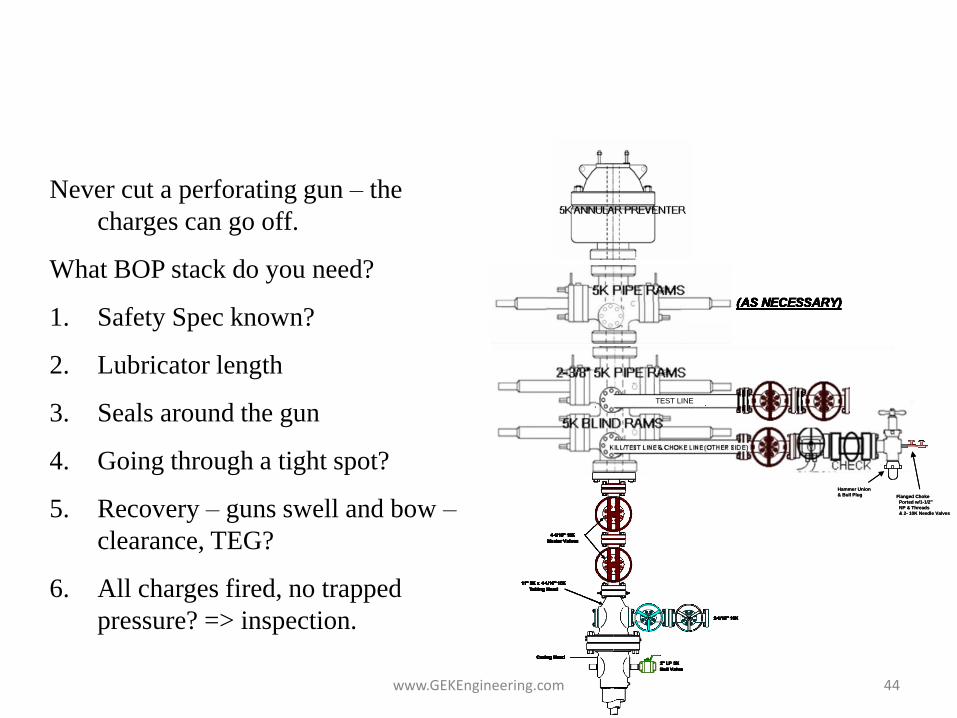
Never cut a perforating gun – the
charges can go off.
What BOP stack do you need?
1. Safety Spec known?
2. Lubricator length
3. Seals around the gun
4. Going through a tight spot?
5. Recovery – guns swell and bow –
clearance, TEG?
6. All charges fired, no trapped
pressure? => inspection.
Barriers for Perforating?
www.GEKEngineering.com 44

Max tool length through the bend area….
Max length of stiff pipe or tool…
L=1/6[R2 - (R - ^d)2]1/2
where:
L = tool length, ft
R = curve radius, inches
^d = ID casing - OD tool (inches)
www.GEKEngineering.com 45

Temperatures in the Well? Circulating or High Rate Injection?
0
2000
4000
6000
8000
10000
12000
14000
16000
18000
30 40 50 60 70 80 90 100 110 120 130
Tubing
Tbg Fluid
Casing 1
Undisturbed
Circulation pump rate = 8-BPM
BHST= 122*F
BHCT= 98*F
0
2000
4000
6000
8000
10000
12000
14000
16000
18000
30 40 50 60 70 80 90 100 110 120 130
Undisturbed
Tbg Fluid
Tubing
Casing 1
Frac job pump rate = 35-BPM
BHST= 125*F
BHTT= 86*F
www.GEKEngineering.com 46

Time at Temperature Graph for Various Perforating Charge Propellants
Guns held over the charge max time-at-temp can burn or auto-detonate.
www.GEKEngineering.com 47

String Shot Techniques
• Aid in back-off and jump-out of coupling.
• Stringshot – 1 to 4 strings of 90 grain (nominal wt) detonation
cord, 3 to 4 ft long, suspended with E-line, across a coupling.
– Initiated high order
– Tension already pulled into pipe (25k+ overpull) or torque when doing a back-off
– May not damage coupling or pin.
www.GEKEngineering.com 48

Debris – After Firing
Most gun debris are from charge
cases and alignment equipment - and
most stays in the gun. However; up
to 20% of the debris may escape
through the port plugs. This may
cause severe problems in sliding
sleeve operations and tool sticking in
smaller liners.
Average amount of debris released
(outside the gun) may be up to 5 lb
per foot of 4” gun. www.GEKEngineering.com 49

Debris – After Firing
Zinc cased perforating charges reduce the size of the debris released.
The released material is also very highly acid soluble. The drawbacks
are slightly less performance and a very rare increase in Zinc scales.
Powdered debris causes less problems in wells with sliding sleeves.
Average size of debris after
firing a zinc cased charge is less
than 200 microns.
Average debris released is 10
lb/ft of four inch guns.
www.GEKEngineering.com 50

When the pipe is not cemented, splits are
very likely with capsule guns and high
density perforating with carrier guns.
Split pipe resulting from perforating in poorly supported pipe
www.GEKEngineering.com 51

Acid Inhibitor Mixing
• Check the inhibitor layer is possible
This will work
pump
Inhibitor
pulled in -
BUT –
major
mixing
energy is
needed
www.GEKEngineering.com 52

Inhibitor Mixing
• What will work? – Air sparging or
rolling the tank with gas
– paddle mixing that creates a vortex
– vigorous rolling
• Effect of oxygen in acid - – oxygen does increase corrosion
– oxygen saturation in acid is 7 parts per billion, so effect of oxygen is limited (not a major factor)
mixer
www.GEKEngineering.com 53

Chrome Pipe Inhibitor Packages
• See the data on inhibitor packages and acids in the Chrome pipe data set.
• Chrome pipe is extremely sensitive to acid – special inhibitors and inhibitor intensifiers are required.
www.GEKEngineering.com 54

Checking the inhibitor presence
• Spectrophotometer
• steel wool test is a presence test – not a quantitative test (placing uncoated 0000 steel wool in uninhibited acid will cause the wool to flow from bubbles of CO2 gas by-product).
• Remember: inhibitor effectiveness is time and temperature dependent - must be replenished after set time.
www.GEKEngineering.com 55

Acidizing and Iron Control
• Problems with iron – sludge catalyst, precipitation in acid jobs, interference with polymers, etc.
• Sources:
– Major – pipe corrosion
– Minor – formation deposits (these react very slowly).
www.GEKEngineering.com 56

Pickling Procedures
• Removes mud, rust, scale, and pipe dope from the ID of the tubing and casing below tubing and displaces it from the tubing, not into the formation.
• It is normally done before any stimulation. – Acid Treatment
– Sand control.
• Reason: pumping of acid and/or proppant will loosen debris from walls of pipe, and will sweep the materials into the perforations.
www.GEKEngineering.com 57

Debris inside of pipe that was cut and pulled from a well. This debris (pipe
dope, mill scale, paraffin, scale, wireline grease, etc.) can be picked up by acid or sand slurries
and carried into the perforations.
www.GEKEngineering.com 58

Tubing Pickling
• What and Why
• How
www.GEKEngineering.com 59

Tubing Pickling
• Pickling removes pipe dope, residual mud, corrosion by-products (rust), mill scale, and other debris.
• Without pickling, the leading edge of the acid or brine sweeps the junk into the perforations and damages the well.
• Failure to effectively pickle or clean the tubing is a leading cause of acid failure.
www.GEKEngineering.com 60

Acid Failures?
• An estimated 70% of acid jobs fail to meet the treating objective.
• About 20% of jobs actually lower the production.
www.GEKEngineering.com 61

Pickling Operations
• Find the best way to remove the debris:
– Acid sweeps
– Abrasive slurry (sand slurry) sweeps
– Solvent sweeps
www.GEKEngineering.com 62

Treating Path
• Clean as much of the tubing as possible without letting the cleaning sweep enter the perforations.
• Alternatives – use coiled tubing to bypass the dirty tubing
www.GEKEngineering.com 63

Pickling Procedure to 8,000 ft (without a Packer)
• Set retrievable bp above perfs
• establish circulation w/ water (+ mutual solvent if oily)
• pump acid at 0.5 to 1 bpm
– new tubing: 200 to 300 gal
– old tubing: 300 to 500 gal
– heavily scaled: 500 to 700 gal
www.GEKEngineering.com 64

Pickling Procedure to 8,000 ft
• Displace w/ water until first 10% of acid is out of tubing
• Reverse acid out of tubing at 0.5 to 1.0 bpm
www.GEKEngineering.com 65
Inhibitors
• All pickle jobs should have a properly selected and blended inhibitor
• An inhibitor will not stop the acid from reacting with iron corrosion (rust), but it will slow the reaction with pipe.
www.GEKEngineering.com 66

Problems
• If an acid pickle is left too long in the pipe, the pipe will be attacked by the acid.
• Sand slurry cleaning sweeps need to be pumped at turbulence.
• Solvent cleaning sweeps must be compatible with other fluids and the seals in the system.
www.GEKEngineering.com 67

Acid Strength
• Should initially return an acid between about 0.5% and a maximum of 3% HCl.
• pH is not a good measurement to check acid strength. Even 0.2% acid strength has a pH lower than 1.
• If HCl strength is more than 3%, reduce acid strength or acid volume in the next comparable job in the area.
www.GEKEngineering.com 68

Initial HCl acid samples loaded with various iron contents. You cannot
tell the level of iron content from visual exam. The samples must be
analyzed. Ideal level of initial iron in the acid is less than 100 ppm.
Most iron comes from tank and pipe contact. Returning iron content is
typically from 500 to over 20,000 ppm, depending on pipe condition and
formation composition.
www.GEKEngineering.com 69

Acid Strength
• Should initially return an acid between about 0.5% and a maximum of 3% HCl.
• pH is not a good measurement to check acid strength. Even 0.2% acid strength has a pH lower than 1.
• If HCl strength is more than 3%, reduce acid strength or acid volume in the next comparable job in the area.
www.GEKEngineering.com 70
Major Iron Problems
• Iron picked up during acidizing is carried into the formation and/or precipitated causing damage.
• Removal of iron is usually by a “pickling” job before the acid job. This is a localized acid flush of the pipe that is flowed back to surface without entering the formation.
www.GEKEngineering.com 71

Pickling with acid – some pipe attack.
www.GEKEngineering.com 72

There are many sources of iron – the majority comes from pipe scale
www.GEKEngineering.com 73

Many forms of FeS – but only a few that are acid soluble.
www.GEKEngineering.com 74

Some loss of carbonate reactivity with iron removal
www.GEKEngineering.com 75

For all around performance, the iron reducing agents are superior to
other forms of iron control.
Much less available iron in a well with no H2S.
www.GEKEngineering.com 76