surprisingly, therefore, valves far but-number any other
TRANSCRIPT
430.13-1
Mechanical Equipment - Course 430.1
VALVES
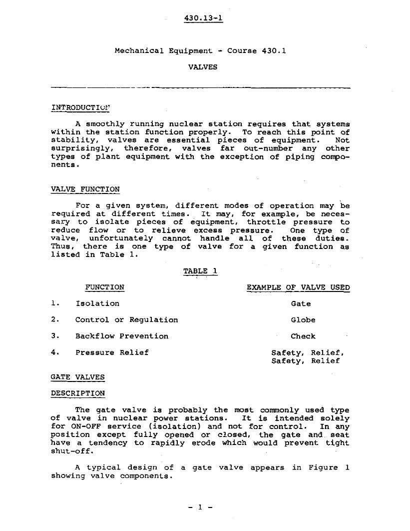
INTRODUCTIOI'
A smoothly running nuclear station requires that systemswithin the station function properly. To reach this point ofstability, valves are essential pieces of equipment. Notsurprisingly, therefore, valves far but-number any othertypes of plant equipment with the exception of piping components.
VALVE FUNCTION
For a given system, different modes of operation may berequired at different times. It may, for example, be necessary to isolate pieces of equipment, throttle pressure toreduce flow or to relieve excess pressure. One type ofvalve, unfortunately cannot handle all of these duties.Thus, there is one type of valve for a given function aslisted in Table 1.
TABLE 1
FUNCTION
Isolation
EXAMPLE OF VALVE USED
Gate
2.
3.
4.
Control or Regulation
Backflow Prevention
Pressure Relief
Globe
Check
Safety, Relief,Safety, Relief
GATE VALVES
DESCRIPTION
The gate valve is probably the most commonly used typeof valve in nuclear power stations. It is intended solelyfor ON-OFF service (isolation) and not for control. In anyposition except fully opened or closed, the gate and, seathave a tendency to rapidly erode which would prevent tightshut-off.
A typical design of a gat.e valve appears in Figure 1showing valve components.
- 1 -

-
--_.-101_-
nuIO
430 13 1. -AlIln_I__ I"l _nut101_
r/ HlndwtI
F111__ _olngm/c ICrWW ring
Yoke_log
A....II. lilting. .
E,-Jlnut
.Glond o,-Jt '/ 1/ /• gIond nut ;i r7
I
Glond 1al_"""1~ / ~SluIIlng box- /
pooIdng '/
No_"""""'- Lon...1/ 1/
..... "'/ ~ ..II I
~I !T
V 177; / 1/e-/ _log
1'\ ~ "\. "- Body
FI.08O/Ill~ S"'-
~Ill _e-. '\ _I
f-J1-:--, u. JJ~ oludo
"" ~ ~i).. "
""""'- \. ""- "-'.70.. " V
Golo Sool ~ng.
Gate- Valve
Figure 1
- 2 -

430.13-1
Valve Components
1. Valva Body - part of the valva which contains and regulates fluid flow.
2. Bonnet - is the valve component that 9ives a closure for-he valve body. To gain access to the seat and disc,the bonnet must normally be removed.' There are a numberof different bonnet types, as indicated below.
(a) SCREW - is the simplest type. In this case thebonnet is screwed directly to the body. It iscommonly found in smaller valves. See Figure 2.
Screw Bonnet
Figure 2
(b) UNION - connects bonnet to body in a manner similarto a standard pipe union employing a gasket forsealing purposes. See Figure 3.
Union Bonnet
Figure 3
- 3 -

430.13-1
(e) BOLTED (Flanged) is used for larger valveswhenever corrosive solutions and high temperatures,pressures may be encountered. The bonnet flange istightened to a body flange using a suitablegasket. See Figure 4.
l::
r ~I.c
\
~
~n. ...
r
Flanged Bonnet
Figure 4
(d) OTHERS - used for high pressuressealed, lip seal and breechlock.
areSee
the pressureFigure 5.
f.1 I.' ,,C(l"Il~~lgliOIiCftcrft,btl
Dad,
,welded COMIClloll
V"ke /
""",~,~,,,,' ,..i'I!4-.,.' f, I
," J>. I. : I, ,
: - r,I I. ,
S"CI;'''\ of rm oul,h:l,,,<..... "lId y,,"
~"j,. Ih""""!1 " II''''''JI'-I~DI • .:I L",,·"'" P, ..,,~, .. ~""" conner CIO"""'l\lu\<.t "~1 ....,,n;"9 0'''11·
Up-'.IIII·bo"nll 9lob••,,1., w;,I, ...... ,d.
""... olld yok•. 8oll".r,b~dy ,h""d.""'y ,lIti., mnha"icQI I"od, wrld acr.lnll Dilly 10 Mal Doc"n., 1,,,10."11'_
Figure 5
S'<li~.. of .01., oI'owi"9 Ih, b."c-'lod, joi"t ~."d for '''9h P""~""' Jh,IllQ. I.on.mlt ti" tlh·....1 On ,h, bon",.to Ih, boo,_
- 4 -

430.13-1
VALVE TRIM (refers to all the wetted parts of a valve excluding the body and bonnet).
3. DISC - is a flat or cylindrical fluid control elementwhich is placed across the fluid pathway to block flow.
4. VALVE SEAT - in order to preven~ downstream leakage whenthe disc is blocking flow there must be a tight fittingclosure between the disc and valve seat. There arethree types of seals possible.
(a) metal-to-metal seal provides the greateststrength but suffers from seizure and galling dueto temperature effects and abrasion.
(b) resilient seal - involves pressing a metal surfaceagainst a plastic or rubber one. This type of sealis usually used whenever a tight seal is requiredfor fluids containing solid particles.
(c) metal-to-metal seal with a resilient insert on oneof the surfaces. This type of seal combinesfeatures of the o~her two types.
5. STEM OR SPINDLE - is the part of thethe disc across the fluid pathway.extends from the disc to the outside
valve used to slideThe stem usually
of the valve.
Different stem arrangements are possible such as:
(a) inside screw non-rising stem - has a disc whichrises as stem screws into it. See Figure 6. Sincestem screws are held within the body, this is anideal arrangement especially where headroom islimited.
INSIDE SCREW, NON-RISING STEM
Figure 6

(b)
430.13-1
inside screw rising stem - has a discas screw turns. See Figure 7. Steamheld within the body. From anviewpoint, therefore, disc positionindicated.
Inside Screw, Rising Stern
Figure 7
- 6 -
which liftsthreads are
operator'sis readily

430.13-1
(c) outside screw rising stem - is a threaded sternwhich moves endwise only. Since the threads tonot contact fluid, this type of stern is ideal forcorrosive and/or high temperature applications.As in (b) the position of the disc is readilyindicated. See Figure 8.
Outside Screw - Rising Stem
Figure 8
- 7 -

430.13-1
6. STEM SEALING - The mast common method of seal ing valvastems is to use a stuffing box packed with a flexibletype of material.
To retain the pressure fluids inside the valve, thepacking is compressed within the stuffing box andagainst the stem by a packing nut or gland.
When there must be absolutely no leakage to the outside,a conventional stem and stUffing box is unsatisfactory.A number of valves that use a packless method of sealingare available, for example:
(a) diaphragm valve - which will be described later.
(b) bellows valve Which uses a metallic bellows betweenthe body and bonnet. See Figure 9.
Bellows Seal
Figure 9
The last two "packless" sealing methods are particularlyuseful in preventing any heavy water leakage. Valves employing these methods are sometimes referred to as zero leakageva1ves •
- 8 -

430.13-1
TYPES OF GATE VALVES
When fUlly opened, gate valves allow straight throughflow in a passage that is equivalent to the inside diameterof the associated pipework. Thus, they impose a minimumpressure drop in the fluid flow system.
Gate valves are classified by the type of disc used.The various types of gate valves are listed below:
1. Solid wedge disc with inclined seat - This type ofshape provides a good metal to metal seal but due to thesolid disc it suffers from expansion effects because ofhigh temperature operation. The expansion effects.result in either valve seizure or poor disc to seatalignment which may lead to leakage. These valves are,therefore. normally found in cold water systems.
2. Flexible wedge disc - Figure 10 is a disc partially cutin halves. This disc type overcomes the temperatureexpansion problem.
Flexible Wedge
Figure 10
- 9 -

430.13-1
(3) Parrallel slide disc valve - Figure 11 - has two discsthat are forced apart against parallel seats at thepoint of closure by a spring. Tight seals result asfluid pressure forces the valve disc against opposingseat.
.....-1.......__ Motor
~_-H---Screwed Spindle
..-__BrldgeI-__'Oland~ Packlng
Stuffing Box
____Sleeve
~_+---,Valve Seat
it!-f--+-_Sprlng~+-_+-_Dlsc
__.JIalve Body
Parallel Slide Valve
Figure 11
- 10 -

430.13-1
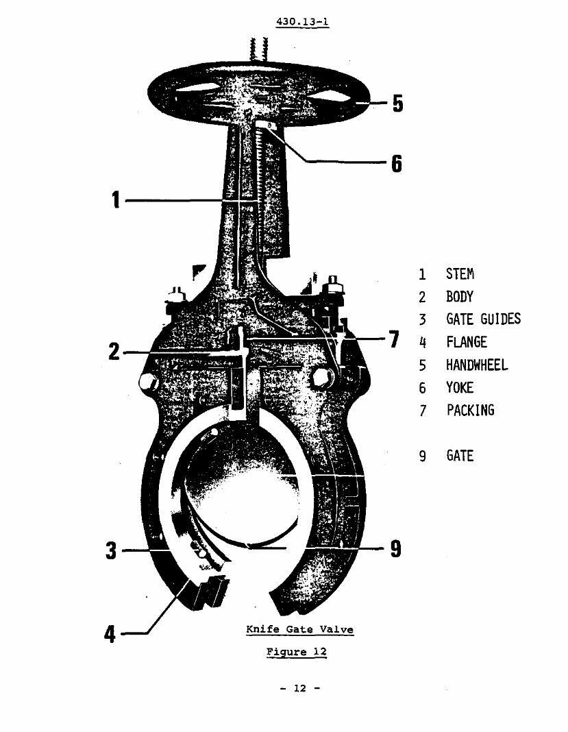
(4) Knife Gate Valves - Figure 12 - have gates consisting ofone or two discs that slide between parallel seats.There is no spreading mechanism: fluid pressure provides effective closure by forcing the downstream surface of the disc against the body seat.
These valves are used in low pressure systems of gasesor liquids.
- 11 -
430.13-1
9 GATE
5
9
'-----6
1 STEM2 BODY3 GATE GUIDES
2 7 4 FLANGE5 HANDWHEEL6 YOKE7 PACKING
1---.....,
3
4--J Knife Gate Valve
Figure 12
- 12 -
430.13-1
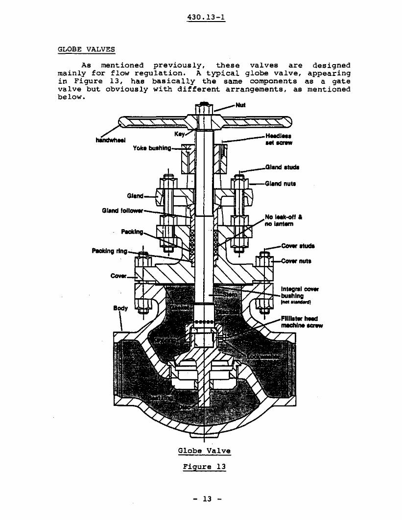
GLOBE VALVES
As mentioned previously, these valves are desig~ed
mainly for flow regulation. A typical globe valve, appear1ngin Figure 13, has basically the same components as a gatevalve but obviously with different arrangements, as mentionedbelow.
___NUl
Key
Voil. bulhlng-n:'A1
__ ----HoodIOlO--
,.__---Glond Itudl
Glond--'- ',"
Giond IOllowor-r~\.r--Ufi.--t--tI
_00-_
i~~iI-_'ntegrl:' coverbulhlng
'""'-
Globe Valve
Figure 13
- 13 -
430.13-1
(1) Flow control for example. is accomplished by a plug ordisc that seats on an orifice arranged at at 90 0 angleto the axis of flow passage. Since flow must make tworight angled turns, pressure drop through the valve ismuch higher than in gate valves.
(2) For liquid service, flnw is directed from underneath theplug. An arrow on the body gives correct flow direct.ion. However, with stearn, flow is in the reverse ofdirect.ion of liquid. By directing the steam from aboveinstead of from below, the stern will remain heated andwill not contract as much if flow was directed frombelow. On valve closure, therefore, a tight seal willbe maintained.
(3) Lastly, the valve body is globular in shape.
TYPES
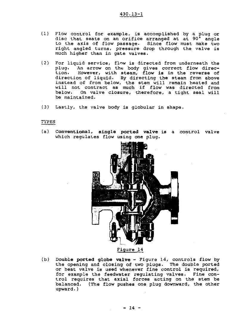
(a) Conventional, single ported val.ve is a control valvewhich regula~es flow using one plug.
Figure 14
(b) Double ported globe val.ve - Figure 14, controls flow bythe opening and closing of two plugs. The double portedor beat valve is used whenever fine control is required,for example the feedwater regUlating valves. Fine control requires that axial forces acting on the stem bebalanced. (The flow pushes one plug downward, the otherupward. )
- 14 -
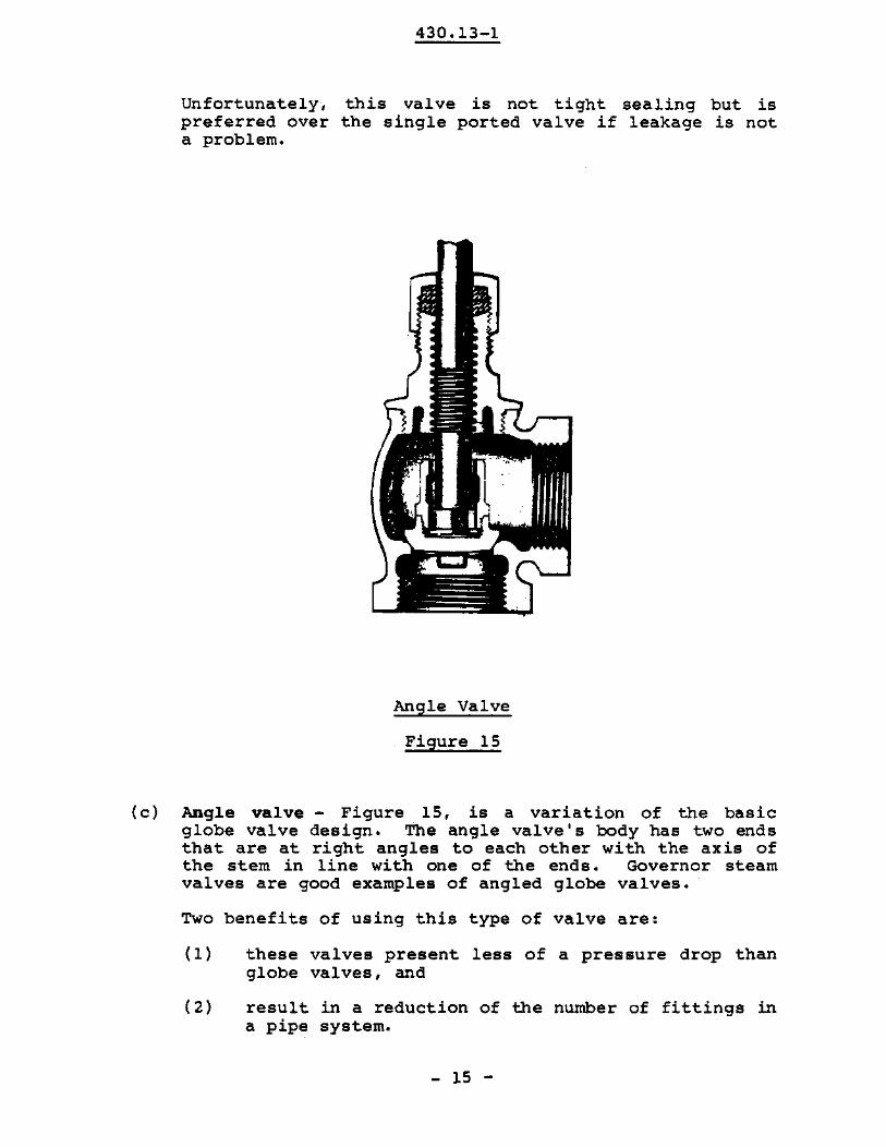
Unfortunately,preferred overa problem.
430.13-1
this valve is not tight sealing but isthe single ported valve if leakage is not
Angle Valve
Figure 15
(c) Angle valve - Figure 15, is a variation of the basicglobe valve design. The angle valvels body has two endsthat are at right angles to each other with the axis ofthe stern in line with one of the ends. Governor steamvalves are good examples of angled globe valves.
Two benefits of using this type of valve are:
(I) these valves present less of a pressure drop thanglobe valves, and
(2) result in a reduction of the number of fittings ina pipe system.
- 15 -

430.13-1
(d) A Y Valve - Figure 16 is similar to a glove valve exceptthe orifice is usually at a 45 0 angle to the flow path.Th.is design givee a low pressure drop across the valveyet with good throttling characteristics.
Y valve showing ~onversion
to angle type
Y-VALVE
Figure 16
(e) Needle valves - Figure 17, allow close regUlation offlow. Generally, a small sized valve, it has a taperedneedle-like plug that fits accurately into the seat.Close regUlation of flow is accomplished because of finethreading.
hdy _
Needle valve showing needlelike clug closed
Needle Valve
Figure 17
- 16 -

430.13-1
CHECK VALVES
These valves are designed to prevent the reversal offlow in piping systems. Automatic in operation, openingresults because of the pressure of the flowing fluidi closurehappens as a result of either back pressure or weight of thecheck mechanism.
TYPES
(a) SWing - has a disk that is hinged at the top. Suitedfor both horizontal or vertical pipework, there islittle pressure drop across the valve. Refer to Figure18.
177:;;~~~~;S:=::HlngopinH1"110
-~"lI
Figure 18
Occasionally swing check valves are equipped with anouts ide lever and weights to keep the valve from openinguntil desired pressure is reached. For example, instrumentedswing check valves employing a piston actuator attached to anoutside lever are found in extraction steam lines to L.P.feedheaters. The instrumental valve ensures quick closurepreventing steam returning to the turbine when the turbinemust be isolated.
- 17 -

430.13-1
(b) With lift check valve., a disk or ball is raised withinguides by the pressure of the upward fluid flow. Whenflow reverses, the check device is forced back onto theseat by backflow and gravity.
(c) The piston tyPe is essentially a disk valve with a dashpot consisting of a piston and cylinder that provides acushioning effect during operation. See Figure 19.More commonly found in horizontal pipework, these valvesare suitable for services which have frequent changes inflow direction. However, higher pressure drops occurthan with the swing type.
Lift Check Valve (Piston)
Figure 19
Check valves serve important roles in the functioning ofpumps. If check valves appear on the dischargeableside, reverse rotation of the impeller is prevented. Onthe suction side, check valves, maintain pumps I primeand are normally referred to as foot valves.
Pump
Figure 20
- 18 -
430.13-1
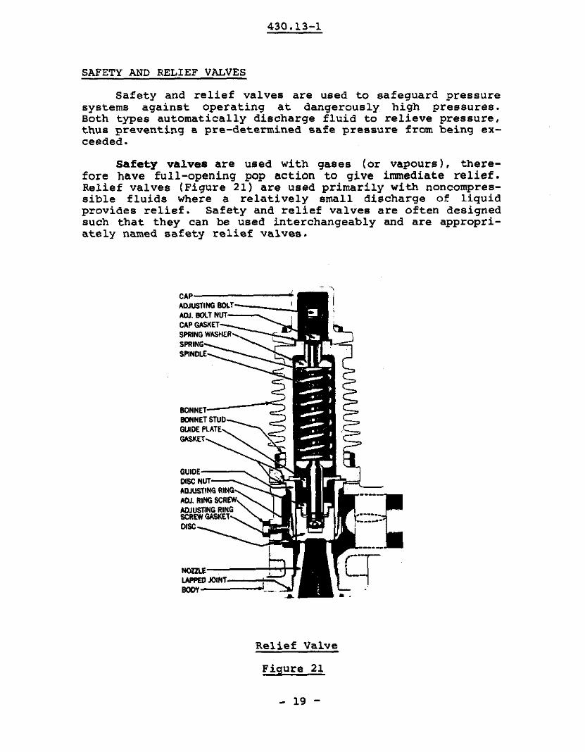
SAFETY AND RELIEF VALVES
Safety and relief valves are used to safeguard pressuresystems against operating at dangerously high pressures.Both types automatically discharge fluid to relieve pressure,thus preventing a pre-determined safe pressure from being exceeded.
safety valves are used with gases (or vapours), therefore have full-opening pop action to give immediate relief.Relief valves (Figure 21) are used primarily with noncompressible fluids where a relatively small discharge of liquidprovides relief. Safety and relief valves are often designedsuah that they can be used interchangeably and are appropriately named safety relief valves.
CAP-------""AOJUSTlNG 110<,,'==:::::--;-ADJ. BOlT NUT-
CAP GASKET-;:::::__~~SPRING WASHERSPRINGSPINDLE
BONNET-----~BONNET STUDGUIDE PLATEGA$l(£T
OUIOE.-;.=:::::,DISC NUTADJUSTING RINGADJ, RING SCRADJUSTING RINGSCREW GASKElDISC
._...~I ~_a_
-_.-cr
Relief Valve
Figure 21
- 19 -

430.13-1
Both safety and relief valves usually operate by thelifting of a spring loaded disk which permits fluid to passthrough. When sufficient pressure acting upward on the discovercomes the force of the spring the valve opens. In safetyvalves, the disk over-hangs the seat to offer additionalthrust area after the initial opening to produce a fasterrise of the disk to the full open position. With relief valves, the area exposed to the over-pressure is constant whet.er the valve is open or closed, the result being a graduallifting of the disc to the full open position. A typicai.safety valve is illustrated in Figure 22.
CAP --------.SPINDLE NUT--__-JADJ. BOLT BEARING - __
FORKED LEVERAOJUSTING BOLTAOJ. BOLT LOCK NUTLEVER- _
SPRING WASHERSPRINGSPINOLE---BONNET----
GUIOE------.GUIOE BEARINGDISC NUT---"'::
OISC HOLDER
OISC INSERT ---....:-z....GUIDE IADJ.! RINGGUIDE RING SET SCRE
NOZZLE RING SET SCREWNOZZLE RING--~
NOZZLEE:====::t::ZBOOY~
Safety Valve
Figure 22
- 20 -

430.13-1
Safety relief valves must combine characteristics ofboth safety and relief valves. For gas service, expansioneffects of the gas provides the additional force underneaththe disc to achieve popping action for immediate full lift.Liquid service also demands full lift in order to have thenozzle orifice control flow rate. To generate the additionalforces underneath the disc, because expansive effects areabsent, the liquid's direction of flow is changed 180 0
• Flowis therefore diverted downward upon contacting the inside ofthe disc holder skirt. This action adds reactive forces tolift the disc. Figure 23 demonstrates the action of a safetyrelief valve.
ADJ. RING
NOZZLE--17/f
BASE
---::-.. ....--~
Figure 23
SPECIAL VALVES
BUTTERFLY VALVES
Built on the pipe damper principle, these valves areespecially suited for large flows of gases and liquids atrelatively low pressures.
Butterfly valves offer a number of Advantages, they are:
(1) present low pressure drops to fluid flow.
(2) do not permit sediment build-up.
(3) are easy to install.
(4) are relatively low priced.
(5) are fast acting, since on quarter turn changes the valvefrom fUlly opened to fully closed.
- 21 -

430.13-1
(6) are light for their size compared with gate valves.
(7) can be used for either isolation or control.
The flow control element of this valve is a disc thatswings on either a horizontal or vertical axis. In theformer case, when the disc lies horizontal, the valve is fullopen, :nd when the disc approaches the vertical position, thevalve ~s shut. See Figure 24.
nt.et---- KEY.,~~~~l~J~~2~::: CIRCLIP.... O·RING
-t>1--- SPINDLE
~~,~~~~~= O·RING~ SEAT"1"1-- SEALING RING
~;~m== DISC PIN, DISC
-'H-t-- 'OOY
.-j2iI+-+--H+--- SEAT CLAMP
STUB SHAFT BEARING
?iji-j-.!f:1JIt--- STUB SHAFT
~$::J;~--O·RING
L
:"';>l«~~3~~:::= ADJUSTERLOCKING SCREW
Wafer Design Butterfly Valve
Figure 24
- 22 -
430.13-1
In Figure 24 and Figure 25, the two types of butterflyvalves are shown:
(1) wafer design_
(2) flange design.
The wafer design is held in place between two pipeflanges by bolts 'that join the two flanges and pass throughholes in the valve's outer casing. The flange design valvehas flanged faces that are joined directly to the pipeflanges.
- 23 -

430.13-1
Flange Butterfly Valve (Piaton Actuator)
Figure 25
- 24 -

430.13-1
Ordinarily, butterfly valves will not close tightly.Leaks are prevented by using resilient seats or O-ring seats.
In the station, butterfly valves may be found either inan isolation or control function.
BALL VALVES
The ball valve is basically a ball with a hole throughone axis that connects the inlet and outlet ports in thebody. The ball rotates between resilient seats. In the openpositicn, the flow is straight-through however, turning theball 90·, completely blocks the passage. Refer to Figure 26 •
---'_-"'8ndI8
B8111_C~::::-1.
BodyTeflon S8Bt_../
Ball Valve
Figure 26
- 25 -
..-_Stem
PATENT D

430.13-1
In addit.ion to quick, quarter-turn, on-off operation,ball valves are compact, easy to maintain, require no lUbrication and give tight sealinq with low torque. Goodsealing:results because fluid pressure force's with ball against thevalve seat. Ball valves can be found for either isolation orcontrol applications.
DIAPHRAGM VALVES
As mentioned previously, the diaphragm valve eliminatesstem packing by using a flexible diaphragm to isolate theoperating mechanisms from the fluid being handled. It consists basically of a body, bonnet, and flexible diaphragm.
DIAPHRAGM CONTROL VALVES'NTRODucnON: The Conoflow Series HBdiaphragm valve maintains a streamlined flowof many hard-to·handle fluids. in a IQkproofclosure. These fluids include corrosive linderosive liquids, slurries, semi-sollds, viscoussubstances, gases, etc. Numerous epplica·tions exist in less difficult services wheresimple packless construction and easy main·tenance are des,,,ble. This valve was formerlyref«!lrred to as a "Saunders Patent·type" afterP. K. Saunders, developer of the basic design.
OPERATION: Principle of the Conoflow SeriesHB diaphragm valve is extremely simple. Aresilient, lIexible diaphragm is connected toa compressor by a stud molded into the dja·phragm. The compressor is moved up anddown by the val.... stem. Thus, when thecompressor is raised, the diaphragm is liftedout of the lIuid path to allow streamlined flowin ejther direction, and is pressed against thebOdy weir when the compressor is lowered.The diaphragm can also be placed in anyintermecliate position for throttling control.
Open Positionc.. .JThrattllna: PoIition
Diaphragm Valves
Figure 27(a)
- 26 -
Closed Pa.ition

430.13-1
Diaphragm Valves
Figure 27(b)
When the valve is opened, the diaphragm is lifted out ofthe flow passage to allow smooth streamlined flow in eitherdirection. In the closed position, the diaphragm is tightlyseated against a weir or contoured area at the bottom of thevalve. It may also be positioned at intermediate points inthe fluid passage for throttling the flow.
The diaphragm "alve is excellent for handling varioussubstances, slurries or corrosive fluids.
- 27 -

430.13-1
PLUG VALVES
Thefamily.
plugLike
valve isthe gate
one of the oldest members of the valvevalve it is used for on-off service.
The basic components of the plug valve are the body,plug and cover. The plug which may be either tapered or cylindrical, has an orifice which the fluid passes through. SeeFigure 28. In operation, the plug may be turned through 90·to allow fluid passage or to presen~ a blank fuse to preventflow.
These valves because of their design offer advantages ofquick action, minimum installation space, simple operation,and low pressure drops.
The two basic types to be considered are the (1) nonlUbricated type which incorporate passages or grooves inwhich lubricant/ sealant can be applied under pressure. Thisserves to lift the plug for ease of operation.
I----+lf-.-JH---f-I 'LUG
PLUG VALVE
Figure 28
- 28 -

430.13-1
ASS1GNMENT
1. Name the four functions that valvesrnust provide and anexample of the valve type used for each function.
2. What are the consequences of using a gate valve forthrottling?
3. Draw and label a typical gate and globe valve. Indicateon the sketch the direction of flow.
40 What type of gate valve would you recommend for:
(a) cold water service?
(b) high pressure, high temperature steam?
Why?
50 What type of globe valve would you recommend for:
(a) fine control for large flows of water regulation?
(b) governor steam valve?
(c) fine control for low flowrate systems?
60 (al Name the two types of nonreturn valves used andcompare them with respect to leakage and pressuredrop across them.
(b) What type of valve would you use for a small pressure drop and vertical pipework use?
(c) The main boiler .feed pumps must not undergo re-verse rotation. Would you, therefore, put thevalve insuction or discharge pipework?
7. What type of pressure relief valvewould be used to depressurize the steam generators? plunger chemical injection pump overpressure relief?
- 29 -

8. (a)
430.13-1
Diaphragm valves can be used for what functions?
(b) What is the main advantage of a diaphragm valve?
(e) Where would you recommend use of diaphragm valves?
9. A large (approximately 2 metre diameter) butterfly valveis used on the discharge condenser circulating waterline.
(a) What are the other advantages of using butterflyvalves?
(b) What function do you think these valves perform?
- 30 -