surgical technique nÁstroje pro … · preparation 2.1. preparation of ... drawing positions of...
TRANSCRIPT

NÁSTROJE PRO ARTROSKOPIIINSTRUMENTS FOR ARTHROSCOPY
SURGICAL TECHNIQUEPROXIMAL TIBIAL PLATE


SURGICAL TECHNIQUE | PROXIMAL TIBIAL PLATE | R00MEDIN, a.s. 1
PROXIMAL TIBIAL PLATE
Proximal Tibial Plate
Description of medical device
The Proximal Tibial Plate is used in epyphyseal and metaphyseal fractures of the proximal end of the tibia. The implantable system consists of a plate and angularly stable or cortical screws. Plates are anatomically shaped and late-rally different for the left and right limb. The distal end is rounded to facilitate easier implementation of mini-invasive insertion. The distal portion is lighter at the bottom of the plate in order to minimize contact and possible compres-sion of the periosteum. In the proximal part, the plate is extended to enable potential insertion of three angularly stable screws under the tibial plateau. In the proximal and distal shaft portion, the plate has holes for angular screws with a diameter of 5 mm. Below the proximal part is positioned an oval ope-ning for attaching using a cortical screw with a diameter of 4.5 mm.
Indication
This surgical technique is intended for both simple dislocated and more complicated, fragmented intra-articular fractures of the proximal end of the tibia, primarily for the treatment of fractures types 41 – A2, A3, B1, B3, C1, C2, C3; based on the Muller classification, and of some storey fractures.
This brochure only serves as an illustrative guide for proximal tibial plates and the instrumentarium. The aim of the brochure is to give physicians and suture nurses a quick guide in the use of the instruments and implant and their composition in order to achieve the best operational outcome. If you have any questions, please contact the MEDIN, a.s. sales representative.
Locking Bone ScrewsØ 5 mm
Proximal tibial platesleft
Proximal tibial platesright
Cannulated Locking Bone Screws Ø 5 mm
Locking Bone ScrewsØ 5/3.5 mm
Cortical Screwsself-tapping Ø 4.5 mm

SURGICAL TECHNIQUE | PROXIMAL TIBIAL PLATE | R00 MEDIN, a.s.2
PROXIMAL TIBIAL PLATE
1. Preoperative planning and principle of surgery technique
The principle of the surgery is the fixation of anatomically repositioned frag-ments using angular stable screws that are secured in the plate. This system functions as an internal fixator and its tasks is to hold the fragments in place while the fracture is healing.
Before surgery, plan the following on preoperative X-rays:
– If it is suitable to use this surgical technique.
– Reposition of fragments or implementation of trans-fixation or additional implants and placement of soft tissue (arteries, nerves…) which must be not be injured during surgery.
– Access, placement and size of the incision.
– The size of the plate or length and screws.
NOTE: It is advisable to take X-ray images of both limbs and compare them in order to achieve the correct reposition.
2. Preparation
2.1. Preparation of implant
2.1.1. Choosing a plate
The implant (plate) is designed specifically for left and right tibia. Plates are supplied in non-sterile versions. Before use, they must be disinfected, washed and sterilized.The length of the plate should be chosen so that the distal half of the plate is outside of fracture area and can be attached to the tibial shaft using screws.
2.2. Preparation of instruments
Before the surgery, it is necessary to check the completeness and functio-nality of all of the instruments. The instruments are supplied in non-sterile versions. Before use, they must be disinfected, washed and sterilized.
3. Surgical technique
3.1. Preoperative preparation
3.2. Positioning of the patient
Place the patient on a surgical table in the supine position, and the limb that the surgery is to be preformed on in such a way that X-rays can be projected in two perpendicular planes.
3.3. Drawing positions of the bones and tendons
It is a good idea to draw on the skin of the patient the place where the incision is to be made, and localization of soft tissue, for better visualization and preoperative planning.
3.4. Incision
Based on the nature of the fracture, the surgeon can choose the anterola-teral (Fig. 1), or the mini-invasive (Fig. 2) approach if the surgeon wants to insert the plate using the minimally invasive technique. Fig. 1 Fig. 2
SURGICAL TECHNIQUE | PROXIMAL TIBIAL PLATE | R00MEDIN, a.s. 3
PROXIMAL TIBIAL PLATE
3.5. Repositioning of the articular surface and the anatomical position and fi xation of the repositioned fragments
3.5.1. Repositioning
Correct repositioning is one of the key components of osteosynthesis. Pay attention to this: it is very important to place the fragments into the origi-nal anatomical position, particularly the fragments of the articular surfaces. Otherwise, it is likely that the patient will feel pain during movement, or limited mobility.
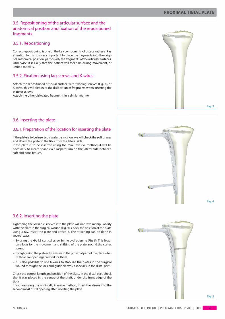
3.5.2. Fixation using lag screws and K-wires
Attach the repositioned articular surface with two “lag screws” (Fig. 3), or K-wires; this will eliminate the dislocation of fragments when inserting the plate or screws.Attach the other dislocated fragments in a similar manner.
3.6. Inserting the plate
3.6.1. Preparation of the location for inserting the plate
If the plate is to be inserted via a large incision, we will check the soft tissues and attach the plate to the tibia from the lateral side.If the plate is to be inserted using the mini-invasive method, it will be necessary to create space via a raspatorium on the lateral side between soft and bone tissues.
3.6.2. Inserting the plate
Tightening the lockable sleeves into the plate will improve manipulability with the plate in the surgical wound (Fig. 4). Check the position of the plate using X-ray. Insert the plate and attach it. The attaching can be done in several ways:
– By using the HA 4.5 cortical screw in the oval opening (Fig. 5). This fi xati-on allows for the movement and shifting of the plate around the cortex screw.
– By tightening the plate with K-wires in the proximal part of the plate whe-re there are openings created for them.
– It is also possible to use K-wires to stabilize the plates in the surgical wound through the lock and guide sleeves, especially in the distal part.
Check the correct length and position of the plate. In the distal part, check that it was placed in the centre of the shaft, under the front edge of the tibia.If you are using the minimally invasive method, insert the sleeve into the second most distal opening after inserting the plate.
Fig. 3
Fig. 4
Fig. 5
SURGICAL TECHNIQUE | PROXIMAL TIBIAL PLATE | R00 MEDIN, a.s.4
PROXIMAL TIBIAL PLATE
3.6.3. Inserting angularly stable screws
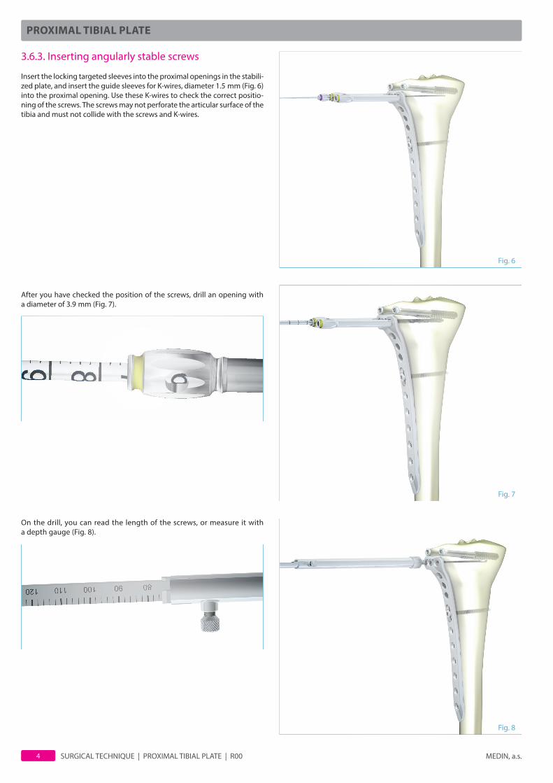
Insert the locking targeted sleeves into the proximal openings in the stabili-zed plate, and insert the guide sleeves for K-wires, diameter 1.5 mm (Fig. 6) into the proximal opening. Use these K-wires to check the correct positio-ning of the screws. The screws may not perforate the articular surface of the tibia and must not collide with the screws and K-wires.
After you have checked the position of the screws, drill an opening with a diameter of 3.9 mm (Fig. 7).
On the drill, you can read the length of the screws, or measure it with a depth gauge (Fig. 8).
Fig. 7
Fig. 6
Fig. 8

SURGICAL TECHNIQUE | PROXIMAL TIBIAL PLATE | R00MEDIN, a.s. 5
PROXIMAL TIBIAL PLATE
!
Only insert the screws in the proximal part monocor-tically. Complete the handle with the torque coupling and 3.5 mm hexagonal screwdriver and insert the screw (Fig. 9).
Apply this procedure for all the screws that are necessary for stable fi xation. In the distal part, below the area of the fracture, insert at least three screws bicortically and insert the fi nal screw monocortically. The force will thus be spread over the last two screws.
The three holes above the oval opening support the three proximal screws under the tibial plateau. Thus, if the tibial plateau width is greater than 65 mm, the maxi-mum length of the fourth and fi fth proximal screws is 55 mm and the sixth proximal screw at most 70 mm. If you insert longer screws, the screws will collide with each other (Fig. 10 and 11).
3.6.4. Inserting other fi xation screws
The instrumentation allows for angularly stable screws with a diameter of 3.5 mm bone thread to be inserted. Pre-drill these screws using a 2.9 mm diameter drill th-rough lockable guide sleeve, diameter of 3.9/3 mm.In certain cases it will be necessary to insert cannulated angularly stable 5 mm diameter screw. This screw is pre-drilled using a cannulated 3.9 mm diameter drill. The cannulated screw and drill is guided using1.5 mm diameter wire.If necessary, it is possible to insert into the plate 4.5 mm diameter cortex screws. To insert these screws, use the instrumentation intended for this purpose.
3.7. Final check and end of surgery
Check the reposition, placement and length of the plate and screws. Take a fi nal X-ray and close the wound with sutures.
3.8. Final comments
a) The various materials can under no circumstances ever be combined for one patient.
b) In order to guarantee the safe use of implants, MEDIN requires that only the recommended implants are used - they may not be combined with implants from other companies.
c) Patients must be informed that the implant will not bear their full weight. Patients must use a means of support while walking, and gradually place more weight on the implant based on how the callus forms at the location of the fracture.
d) The implants are intended for one use; repeated use is prohibited.
Fig. 9
Fig. 11Fig. 10
screw lengthmax. 55 mm
screw lengthmax. 70 mm

SURGICAL TECHNIQUE | PROXIMAL TIBIAL PLATE | R00 MEDIN, a.s.6
PROXIMAL TIBIAL PLATE
3.9. Recommended procedure for extrac-ting the implant
The implants may be left in permanently if the risks associ-ated with extracting them are more serious that the reasons to extract them. We recommend the potential extracting of the implants after a minimum of 12 months from when they were implanted, after a callus has formed and the fracture has healed – unless there are reasons to extract them earlier.
Extraction procedure:
– Loosening of screws (Fig. 12)
– Removal of screws (Fig. 13)
– Extraction of plate (Fig. 14)
4. Follow up
After the surgery, it is necessary to examine motion. We recommend a CT scan to check the correct fi xation to the joint. On the fi rst postoperative day the patient will begin to practice mobility in the knee joint. Gradual load on the limb is possible only after 6–8 weeks after the operation, depending on the forming of the callus. Full load placed on the joint is only possible 10 weeks after surgery.An X-ray is recommended after surgery: at 2, 4 and 8 weeks.
Fig. 12
Fig. 13
Fig. 14

SURGICAL TECHNIQUE | PROXIMAL TIBIAL PLATE | R00MEDIN, a.s. 7
PROXIMAL TIBIAL PLATE
5. Set of instruments
Set of instruments for 5 mm angularly stable screws 139 09 0260Sieve for instruments 129 69 5180Sieve for tibial proximal plates 129 69 5920
Instruments:
pcs Name order number2 Guide sleeve Ø 3.9/1.8 mm 129 69 44102 Guide sleeve Ø 3.9/2.9 mm 129 69 44304 Aiming sleeve lockable Ø 6.8/3.9×80 mm 129 69 43001 Screwdriver handle 129 69 51302 Screwdriver; hexagon 3.5 mm 129 69 52612 Screwdriver; hexagon 3.5 mm 129 69 52511 Depth gauge 129 79 89101 Drill Ø 3.9×220; cannulated 129 69 44011 Drill Ø 2.9×220 129 69 52011 Drill Ø 3.9×220 129 69 51413 K-wire MEDIN 1.5×300 mm 129 09 25501 Torque limiter 4 Nm 129 69 5121
Recommended equipment in addition to the basic surgery set:
1. Retractor2. Hook3. Elevator4. Pliers for K-wires5. Scalpel6. Sutures7. Suction pump8. Coagulation 9. Raspatorium
Recommended cleaning method
1. Mechanically cleaned with water using a brush. 2. Rinse instruments with pressurized water3. Place the instruments into disinfectant solution for 20 to 30 minutes. Our
recommended disinfectant is KORSOLEX plus. If you are using another solution, there is risk of damage to the instruments.
4. Re-fl ush using pressured water until clean water begins fl owing. Flushing is possible in conventional pressure washers when connecting the instru-ments to jets.
5. Blow the instruments with compressed air.
Recommended sterilization procedure
Before use, the instruments should be thoroughly washed and disinfected. We recommend steam sterilization. The sterilization temperature must not exceed 135 °C. If the temperature exceeds 135 °C, the plastic parts and colour coding of the instruments will be degraded. Instruments damaged in such a way must not be put into use.
SURGICAL TECHNIQUE | PROXIMAL TIBIAL PLATE | R00 MEDIN, a.s.8
PROXIMAL TIBIAL PLATE
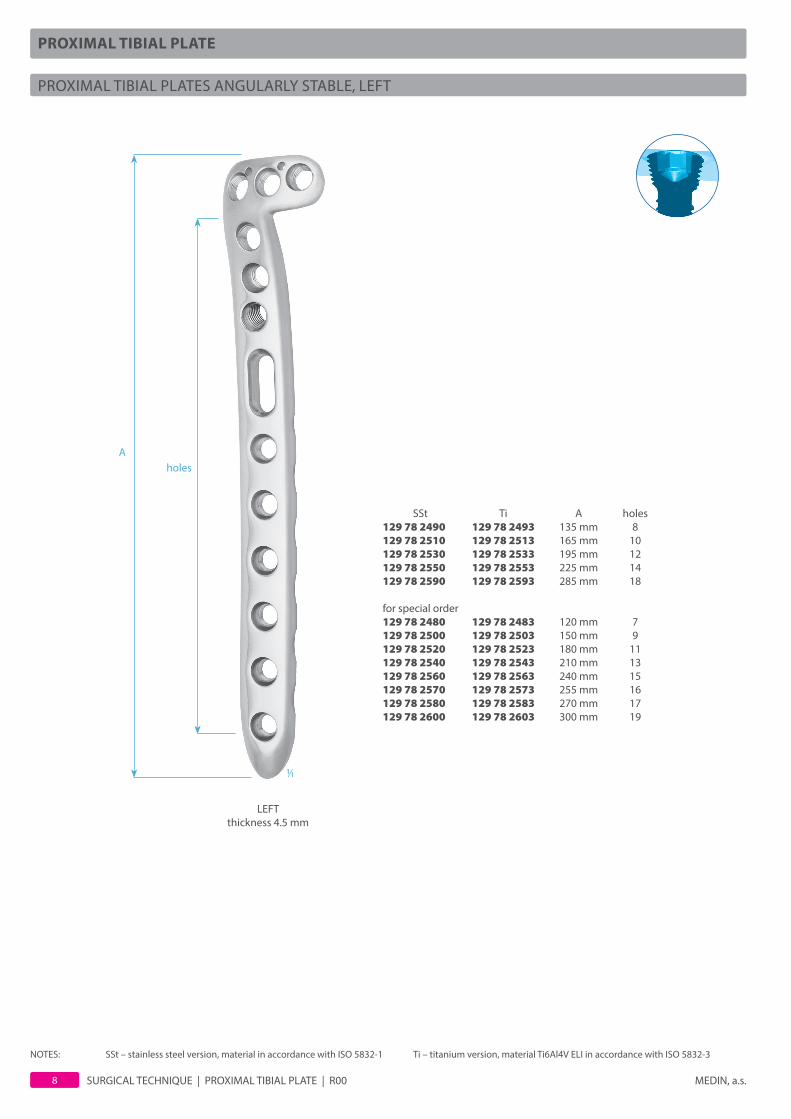
PROXIMAL TIBIAL PLATES ANGULARLY STABLE, LEFT
1/1
holes
LEFTthickness 4.5 mm
A
SSt Ti A holes129 78 2490 129 78 2493 135 mm 8129 78 2510 129 78 2513 165 mm 10129 78 2530 129 78 2533 195 mm 12129 78 2550 129 78 2553 225 mm 14129 78 2590 129 78 2593 285 mm 18
for special order129 78 2480 129 78 2483 120 mm 7129 78 2500 129 78 2503 150 mm 9129 78 2520 129 78 2523 180 mm 11129 78 2540 129 78 2543 210 mm 13129 78 2560 129 78 2563 240 mm 15129 78 2570 129 78 2573 255 mm 16129 78 2580 129 78 2583 270 mm 17129 78 2600 129 78 2603 300 mm 19
NOTES: SSt – stainless steel version, material in accordance with ISO 5832-1 Ti – titanium version, material Ti6Al4V ELI in accordance with ISO 5832-3

SURGICAL TECHNIQUE | PROXIMAL TIBIAL PLATE | R00MEDIN, a.s. 9
PROXIMAL TIBIAL PLATE
PROXIMAL TIBIAL PLATES ANGULARLY STABLE, RIGHT
1/1
RIGHTthickness 4.5 mm
SSt Ti A holes129 78 2350 129 78 2353 135 mm 8129 78 2370 129 78 2373 165 mm 10129 78 2390 129 78 2393 195 mm 12129 78 2410 129 78 2413 225 mm 14129 78 2450 129 78 2453 285 mm 18
for special order129 78 2340 129 78 2343 120 mm 7129 78 2360 129 78 2363 150 mm 9129 78 2380 129 78 2383 180 mm 11129 78 2400 129 78 2403 210 mm 13129 78 2420 129 78 2423 240 mm 15129 78 2430 129 78 2433 255 mm 16129 78 2440 129 78 2443 270 mm 17129 78 2460 129 78 2463 300 mm 19
holesA
NOTES: SSt – stainless steel version, material in accordance with ISO 5832-1 Ti – titanium version, material Ti6Al4V ELI in accordance with ISO 5832-3

SURGICAL TECHNIQUE | PROXIMAL TIBIAL PLATE | R00 MEDIN, a.s.10
PROXIMAL TIBIAL PLATE
LOCKING BONE SCREWS 5 mm
CANNULATED LOCKING BONE SCREWS 5 mm
1/1
Ø 5 mm
A
1/1Ø 5 mm
A
SSt Ti A 129 77 7981 129 77 7984 16 mm 129 77 7991 129 77 7994 18 mm 129 77 8001 129 77 8004 20 mm 129 77 8011 129 77 8014 22 mm 129 77 8021 129 77 8024 24 mm 129 77 8031 129 77 8034 26 mm 129 77 8041 129 77 8044 28 mm 129 77 8051 129 77 8054 30 mm 129 77 8061 129 77 8064 32 mm 129 77 8071 129 77 8074 34 mm 129 77 8081 129 77 8084 36 mm 129 77 8091 129 77 8094 38 mm 129 77 8101 129 77 8104 40 mm 129 77 8111 129 77 8114 42 mm 129 77 8121 129 77 8124 44 mm 129 77 8131 129 77 8134 46 mm 129 77 8141 129 77 8144 48 mm 129 77 8151 129 77 8154 50 mm 129 77 8161 129 77 8164 55 mm 129 77 8171 129 77 8174 60 mm 129 77 8181 129 77 8184 65 mm 129 77 8191 129 77 8194 70 mm 129 77 8201 129 77 8204 75 mm 129 78 7401 129 78 7404 80 mm 129 78 7411 129 78 7414 85 mm 129 78 7421 129 78 7424 90 mm 129 78 7431 129 78 7434 95 mm 129 78 7441 129 78 7444 100 mm 129 78 7451 129 78 7454 105 mm
SSt Ti A 129 77 8681 129 77 8684 16 mm 129 77 8691 129 77 8694 18 mm 129 77 8701 129 77 8704 20 mm 129 77 8711 129 77 8714 22 mm 129 77 8721 129 77 8724 24 mm 129 77 8731 129 77 8734 26 mm 129 77 8741 129 77 8744 28 mm 129 77 8751 129 77 8754 30 mm 129 77 8761 129 77 8764 23 mm 129 77 8771 129 77 8774 34 mm 129 77 8781 129 77 8784 36 mm 129 77 8791 129 77 8794 38 mm 129 77 8801 129 77 8804 40 mm 129 77 8811 129 77 8814 42 mm 129 77 8821 129 77 8824 44 mm 129 77 8831 129 77 8834 46 mm 129 77 8841 129 77 8844 48 mm 129 77 8851 129 77 8854 50 mm 129 77 8861 129 77 8864 55 mm 129 77 8871 129 77 8874 60 mm 129 77 8881 129 77 8884 65 mm 129 77 8891 129 77 8894 70 mm 129 77 8901 129 77 8904 75 mm 129 78 7541 129 78 7544 80 mm 129 78 7551 129 78 7554 85 mm 129 78 7561 129 78 7564 90 mm 129 78 7571 129 78 7574 95 mm 129 78 7581 129 78 7584 100 mm 129 78 7591 129 78 7594 105 mm
CANNULATED
NOTES:drilled with Ø 3.9 mm drill introduction by a screwdriver with 3.5 mm socket
NOTES:drilled with Ø 3.9 mm cannulated drill introduction by a screwdriver with 3.5 mm socketguide wire Ø 1.5 mm
NOTES: SSt – stainless steel version, material in accordance with ISO 5832-1 Ti – titanium version, material Ti6Al4V ELI in accordance with ISO 5832-3

SURGICAL TECHNIQUE | PROXIMAL TIBIAL PLATE | R00MEDIN, a.s. 11
PROXIMAL TIBIAL PLATE
LOCKING BONE SCREWS 5/3.5 mm
SSt Ti A 129 77 8231 129 77 8234 16 mm 129 77 8241 129 77 8244 18 mm 129 77 8251 129 77 8254 20 mm 129 77 8261 129 77 8264 22 mm 129 77 8271 129 77 8274 24 mm 129 77 8281 129 77 8284 26 mm 129 77 8291 129 77 8294 28 mm 129 77 8301 129 77 8304 30 mm 129 77 8311 129 77 8314 32 mm 129 77 8321 129 77 8324 34 mm 129 77 8331 129 77 8334 36 mm 129 77 8341 129 77 8344 38 mm 129 77 8351 129 77 8354 40 mm 129 77 8361 129 77 8364 42 mm 129 77 8371 129 77 8374 44 mm 129 77 8381 129 77 8384 46 mm 129 77 8391 129 77 8394 48 mm 129 77 8401 129 77 8404 50 mm 129 77 8411 129 77 8414 55 mm 129 77 8421 129 77 8424 60 mm 129 77 8431 129 77 8434 65 mm 129 77 8441 129 77 8444 70 mm 129 77 8451 129 77 8454 75 mm 129 78 7471 129 78 7474 80 mm 129 78 7481 129 78 7484 85 mm 129 78 7491 129 78 7494 90 mm 129 78 7501 129 78 7504 95 mm 129 78 7511 129 78 7514 100 mm 129 78 7521 129 78 7524 105 mm
1/1Ø 3,5 mm
A
NOTES:drilled with Ø 2.9 mm drill introduction by a screwdriver with 3.5 mm socket
NOTES: SSt – stainless steel version, material in accordance with ISO 5832-1 Ti – titanium version, material Ti6Al4V ELI in accordance with ISO 5832-3
SELF-TAPPING CORTICAL BONE SCREWS – HA 4.5 mm
SSt Ti A 129 79 9421 129 79 9424 14 mm 129 79 9431 129 79 9434 16 mm 129 79 9441 129 79 9444 18 mm 129 79 5521 129 79 5524 20 mm 129 79 9451 129 79 9454 22 mm 129 79 9461 129 79 9464 24 mm 129 79 5541 129 79 5544 26 mm 129 79 9471 129 79 9474 28 mm 129 79 5551 129 79 5554 30 mm 129 79 9481 129 79 9484 32 mm 129 79 9491 129 79 9494 34 mm 129 79 5571 129 79 5574 36 mm 129 79 9501 129 79 9504 38 mm 129 79 5581 129 79 5584 40 mm 129 79 9511 129 79 9514 42 mm 129 79 9521 129 79 9524 44 mm 129 79 9531 129 79 9534 46 mm 129 79 9541 129 79 9544 48 mm 129 79 5601 129 79 5604 50 mm 129 79 9551 129 79 9554 52 mm 129 79 9561 129 79 9564 54 mm 129 79 9571 129 79 9574 56 mm 129 79 9581 129 79 9584 58 mm 129 79 5621 129 79 5624 60 mm 129 79 5631 129 79 5634 65 mm 129 79 5641 129 79 5644 70 mm 129 79 5651 129 79 5654 75 mm 129 79 5661 129 79 5664 80 mm 129 79 5671 129 79 5674 85 mm 129 79 5681 129 79 5684 90 mm 129 79 5691 129 79 5694 95 mm 129 79 5701 129 79 5704 100 mm 129 79 5711 129 79 5714 105 mm 129 79 5721 129 79 5724 110 mm
1/1
Ø 4,5 mm
A
NOTES:drilled with Ø 3.2 mm drill introduction by a screwdriver with 3.5 mm socket

SURGICAL TECHNIQUE | PROXIMAL TIBIAL PLATE | R00 MEDIN, a.s.12
PROXIMAL TIBIAL PLATE
dlah
a_tib
ialn
i_pr
oxim
alni
_OP0
23EN
-R00
_201
3-04
-19
number of pcs 1 129 09 2550 K-wire MEDIN Ø 1.5 mm; 300 mm 3 2 129 69 4300 Aiming sleeve lockable Ø 6.8/Ø 4 mm; 80 mm 4 3 129 69 4401 Cannulated drill Ø 3.9 mm; 220 mm 1 4 129 69 4410 Guide sleeve Ø 4/1.8 mm; 95 mm 2 5 129 69 4430 Guide sleeve Ø 4/3 mm; 95 mm 2 6 129 69 5121 Torque limiter 4 Nm 1 7 129 69 5130 Screwdriver handle 1 8 129 69 5141 Drill Ø 3.9 mm; 220 mm 1 9 129 69 5201 Drill Ø 2.9 mm; 220 mm 1 10 129 69 5251 Screwdriver; hexagon 3.5 mm 2 11 129 69 5261 Cannulated screwdriver; hexagon 3.5 mm 2 12 129 79 8910 Depth gauge for screws Ø 4.5–6.5 mm 1
139 09 0260set
34 6 789 1 10 11122 5
Instruments for angularly stable plates with screws 3,5 and 5/3,5 mm139 09 0265
540 × 240 × 90 mmsieve with instruments
INSTRUMENTS FOR ANGULARLY STABLE PLATES WITH SCREWS 5 mm

© 2012 MEDIN, a.s.; All rights reserved.This document should be used for commercial purposes of MEDIN, a.s.; the data mentioned in the document has informative character. No part of this document can be copied or published in any form without approval of MEDIN, a.s. The product design may differ from those depicted in these illustrations at the date of issue. Adjustments, made from the reason of further developments of technical parameters, are reserved. Printing and typographical errors are reserved.
SURGICAL TECHNIQUE | PROXIMAL TIBIAL PLATE | R00MEDIN, a.s. 13
PROXIMAL TIBIAL PLATE
STANDS FOR LOCKING SCREWS
Stand for locking screws 5/3,5129 69 6390
214 × 126 mmheight 120 mm
Stand for locking screws 5129 69 5741
214 × 186 mmheight 120 mm
Stand for cannulated locking screws 5129 69 6395
214 × 126 mmheight 120 mm

2013