surge control strategies for wastewater conveyance · pdf filesurge control strategies for...
TRANSCRIPT
water resource specialists
SURGE CONTROL STRATEGIES FOR WASTEWATER CONVEYANCE SYSTEMS
Overview
Consequences of surge eventsEvents that create pressure surgesSurge control strategiesSurge analysis objectives and criteriaSurge analysis projects Concluding remarks / Q&A
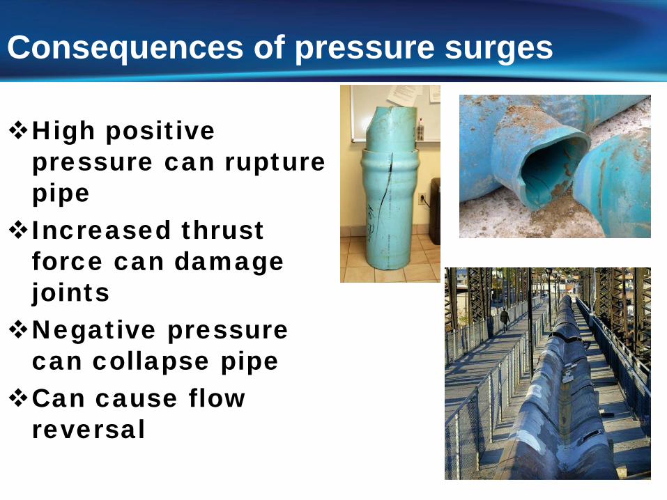
Consequences of pressure surges
High positive pressure can rupture pipe
Increased thrust force can damage joints
Negative pressure can collapse pipe
Can cause flow reversal
Events that create pressure surges in wastewater systemsPump power failure (creates the worst-
case surge events)Pump shutdown/startupPipeline rupture
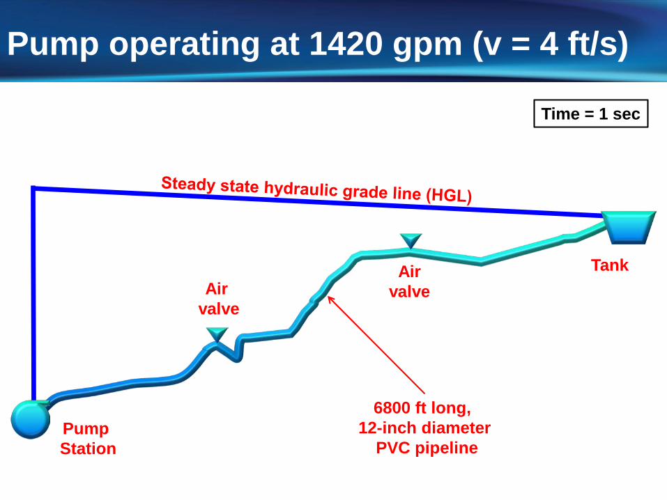
Pump operating at 1420 gpm (v = 4 ft/s)
Time = 1 sec
Airvalve
Airvalve
PumpStation
Tank
6800 ft long, 12-inch diameter
PVC pipeline
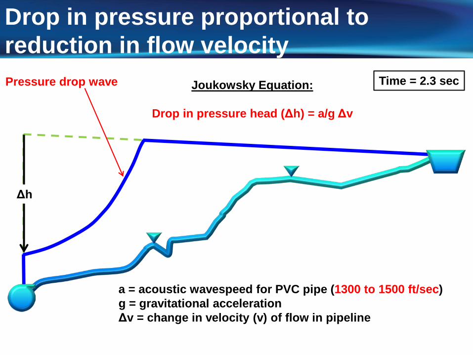
Drop in pressure proportional to reduction in flow velocity
Time = 2.3 sec
a = acoustic wavespeed for PVC pipe (1300 to 1500 ft/sec)g = gravitational accelerationΔv = change in velocity (v) of flow in pipeline
Δh
Joukowsky Equation:
Drop in pressure head (Δh) = a/g Δv
Pressure drop wave
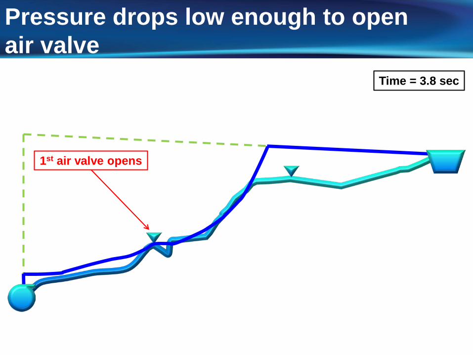
Pressure drops low enough to openair valve
Time = 3.8 sec
1st air valve opens
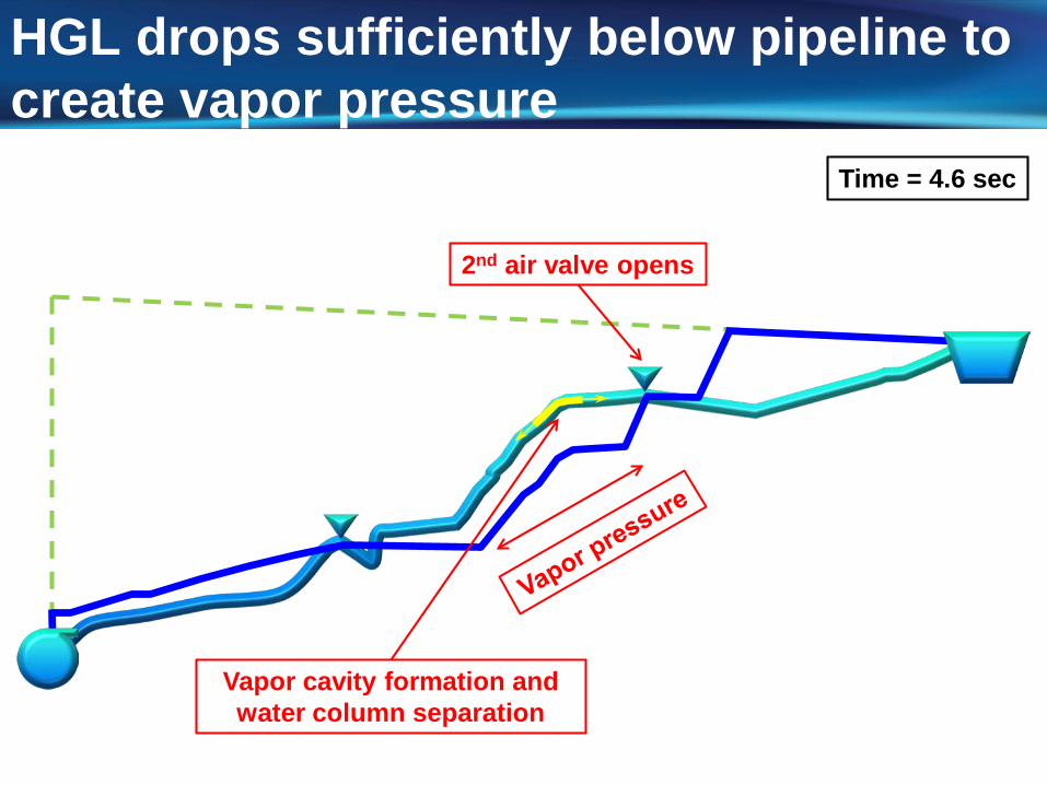
HGL drops sufficiently below pipeline to create vapor pressure
Vapor cavity formation and water column separation
Time = 4.6 sec
2nd air valve opens
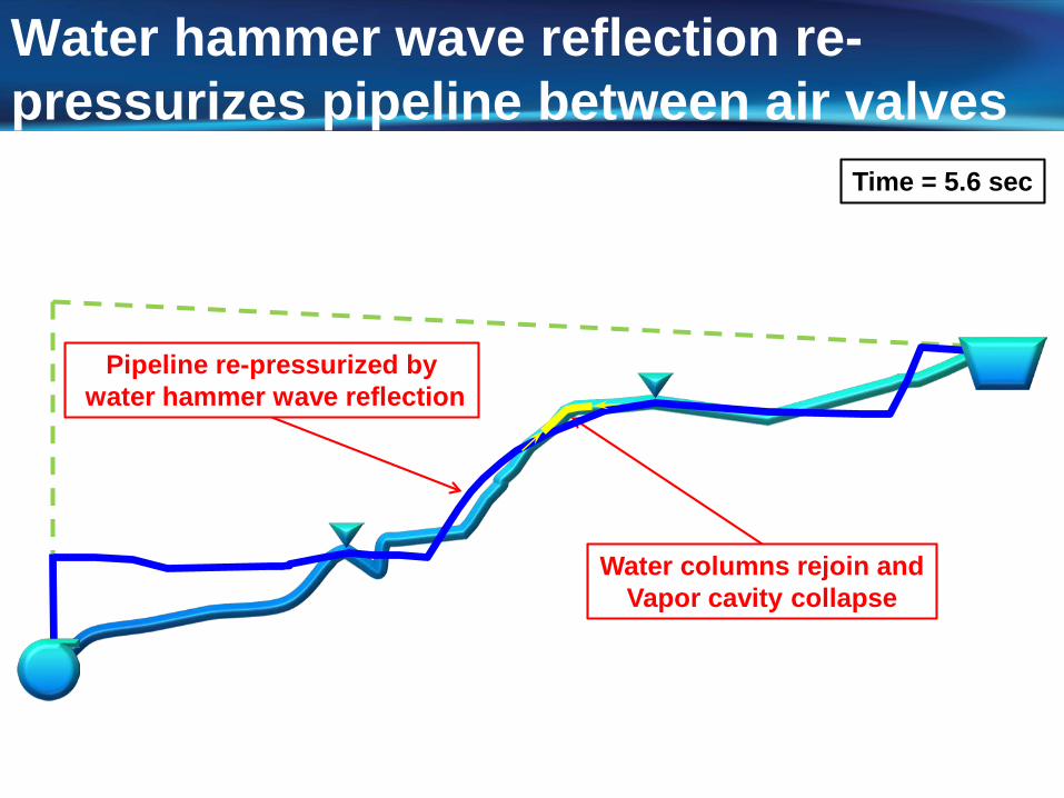
Water hammer wave reflection re-pressurizes pipeline between air valves
Pipeline re-pressurized bywater hammer wave reflection
Water columns rejoin andVapor cavity collapse
Time = 5.6 sec
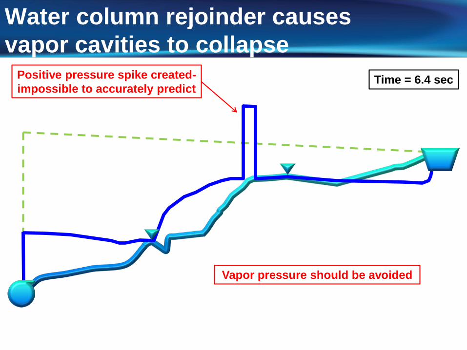
Water column rejoinder causesvapor cavities to collapse
Positive pressure spike created-impossible to accurately predict
Time = 6.4 sec
Vapor pressure should be avoided
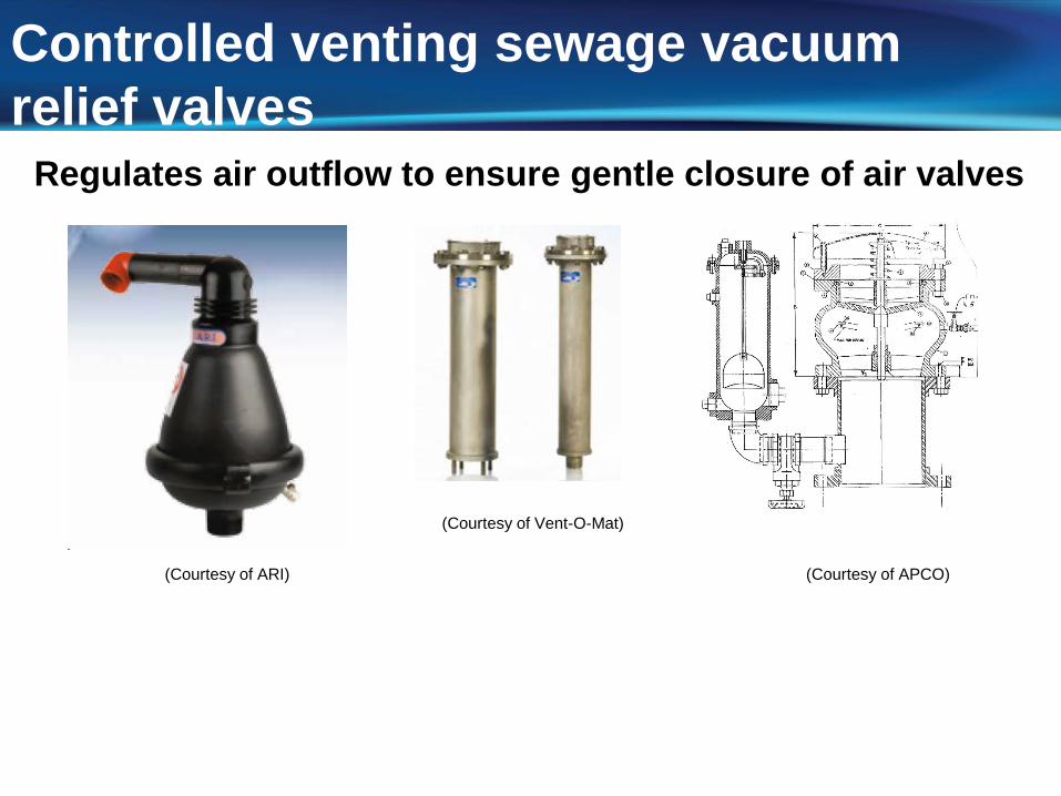
Controlled venting sewage vacuum relief valves
Regulates air outflow to ensure gentle closure of air valves
(Courtesy of ARI)
(Courtesy of Vent-O-Mat)
(Courtesy of APCO)
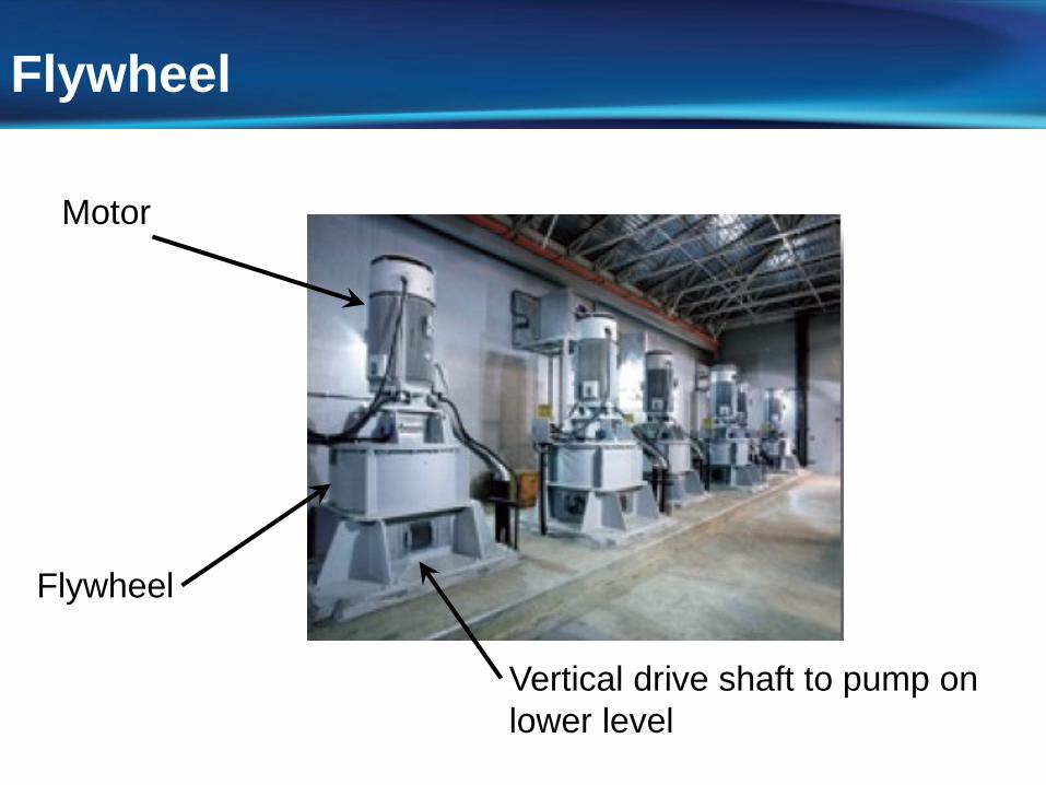
Flywheel
Vertical drive shaft to pump on lower level
Motor
Flywheel
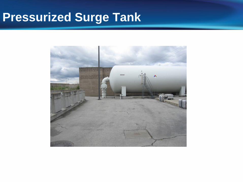
Pressurized Surge Tank
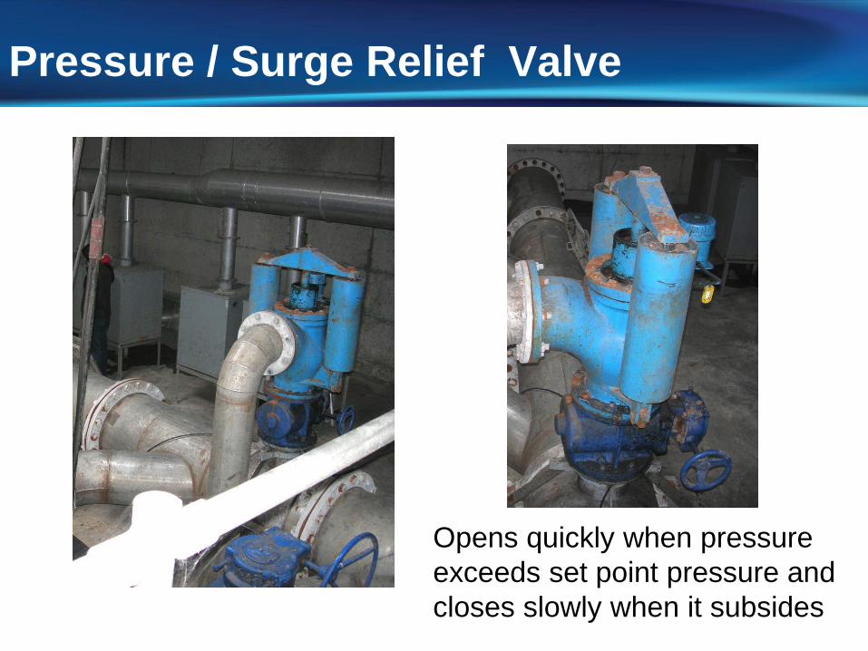
Pressure / Surge Relief Valve
Opens quickly when pressure exceeds set point pressure andcloses slowly when it subsides
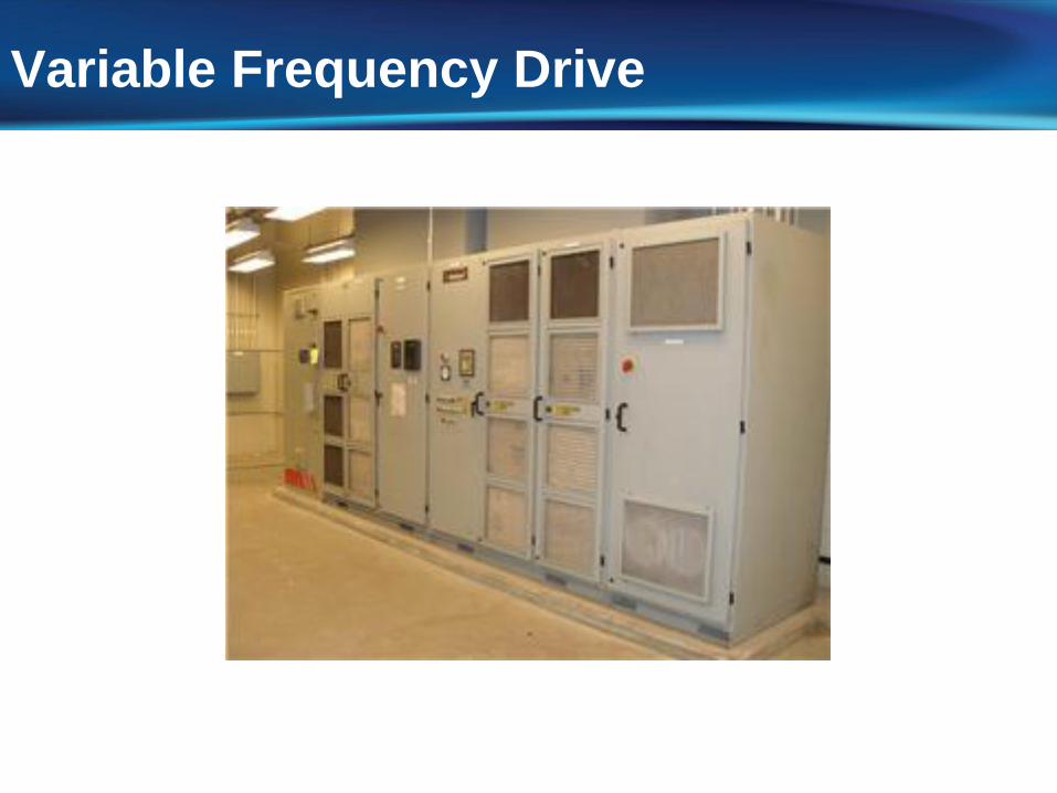
Variable Frequency Drive
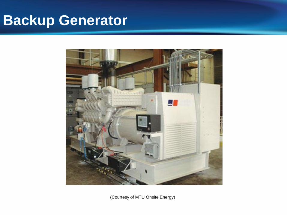
Backup Generator
(Courtesy of MTU Onsite Energy)
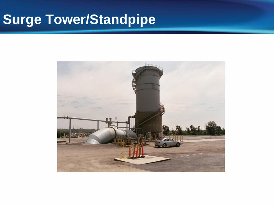
Surge Tower/Standpipe
Objectives of Surge Analysis
Identify potential adverse surge pressuresIf needed, recommend additional surge
control measures
Air entrainment in wastewater
Recommend safe startup and shutdown procedures for pumps
Surge Control Design Criteria
Limit positive surge pressures to ~30 percent over the larger of static, working, or rated pressure
Eliminate large negative pressures and vapor pressure
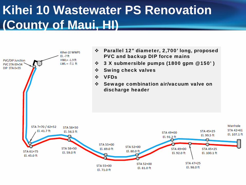
Kihei 10 Wastewater PS Renovation (County of Maui, HI)
Parallel 12” diameter, 2,700’ long, proposed PVC and backup DIP force mains
3 X submersible pumps (1800 gpm @ 150’ ) Swing check valves VFDs Sewage combination air/vacuum valve on
discharge header
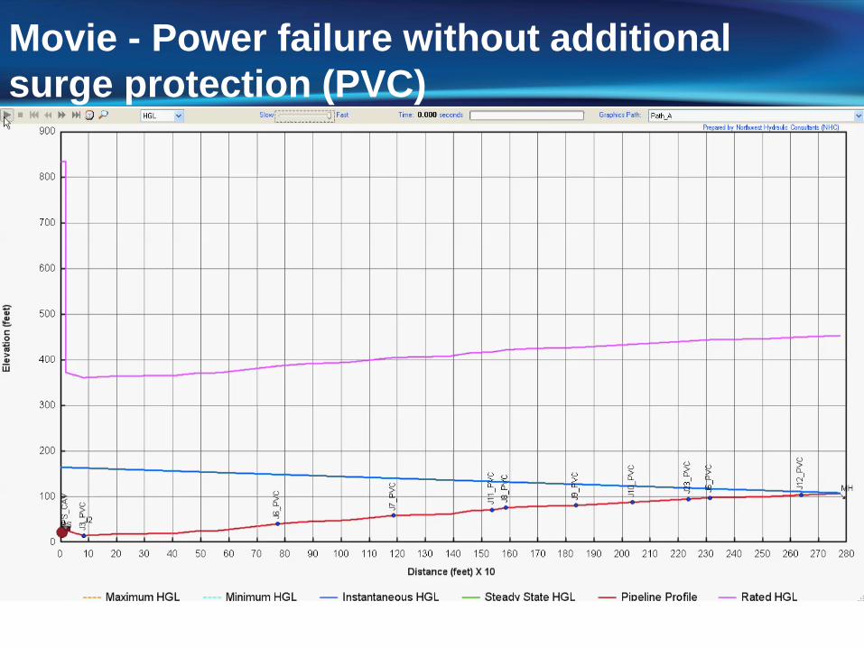
Movie - Power failure without additional surge protection (PVC)
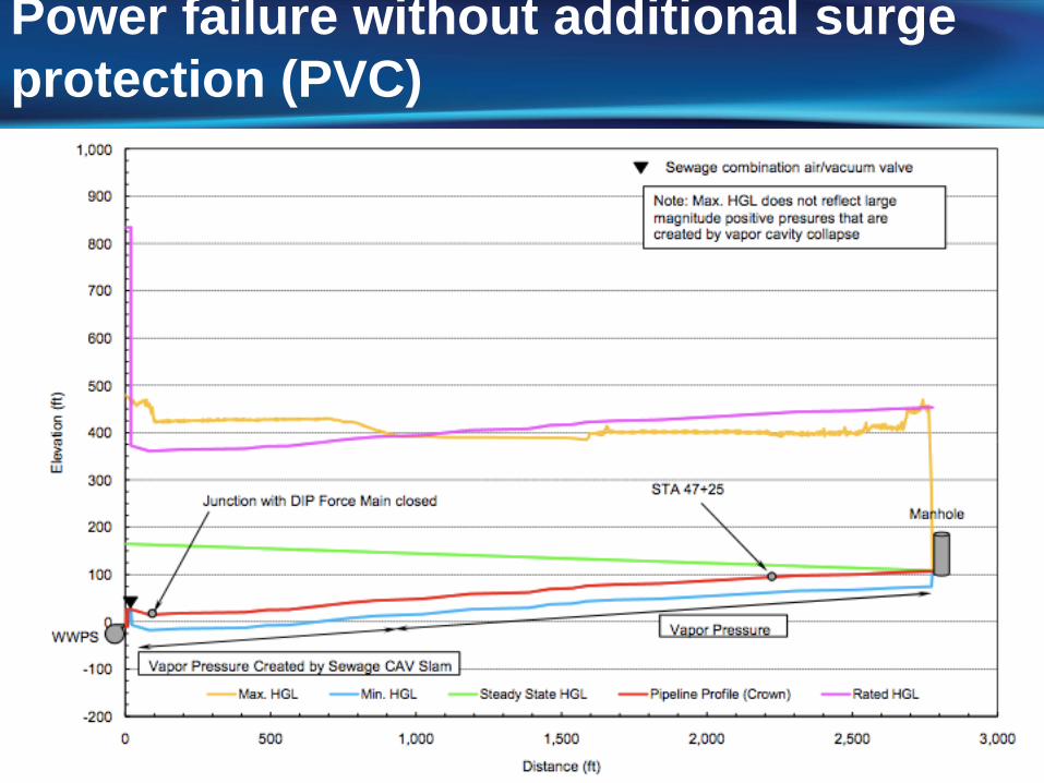
Power failure without additional surge protection (PVC)
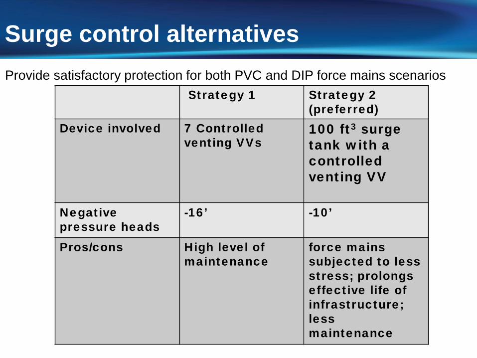
Strategy 1 Strategy 2 (preferred)
Device involved 7 Controlled venting VVs
100 ft3 surge tank with a controlled venting VV
Negative pressure heads
-16’ -10’
Pros/cons High level of maintenance
force mains subjected to less stress; prolongs effective life of infrastructure;less maintenance
Surge control alternativesProvide satisfactory protection for both PVC and DIP force mains scenarios
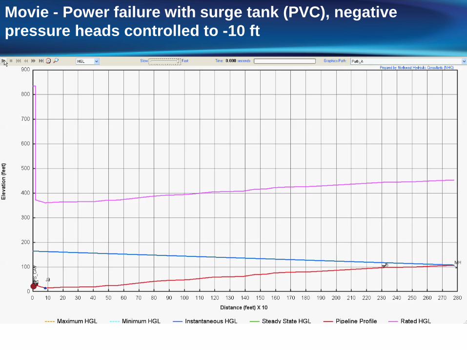
Movie - Power failure with surge tank (PVC), negative pressure heads controlled to -10 ft
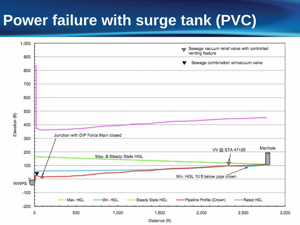
Power failure with surge tank (PVC)
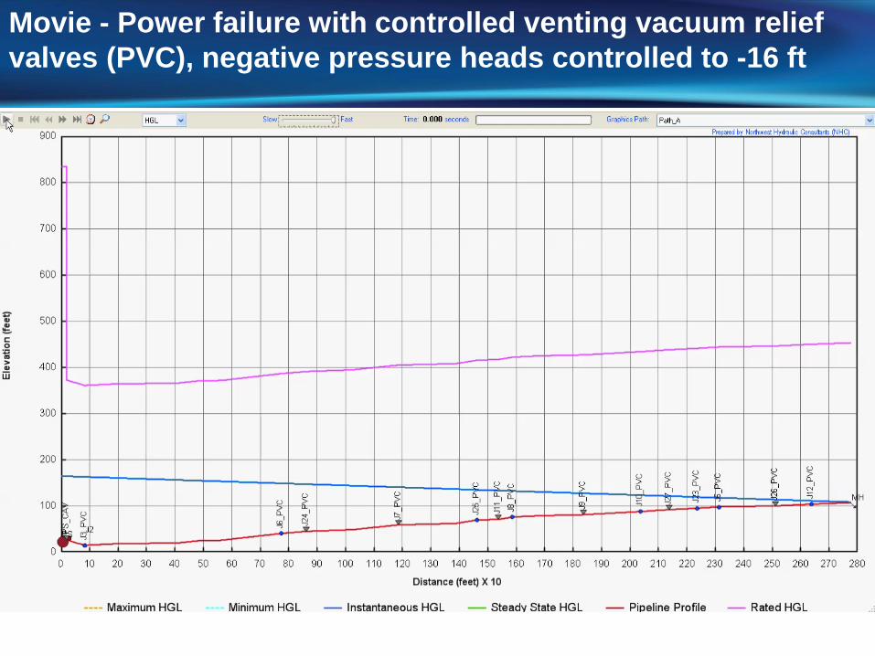
Movie - Power failure with controlled venting vacuum relief valves (PVC), negative pressure heads controlled to -16 ft
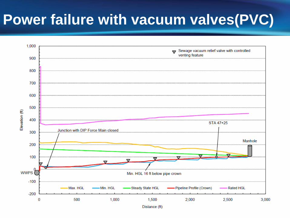
Power failure with vacuum valves(PVC)
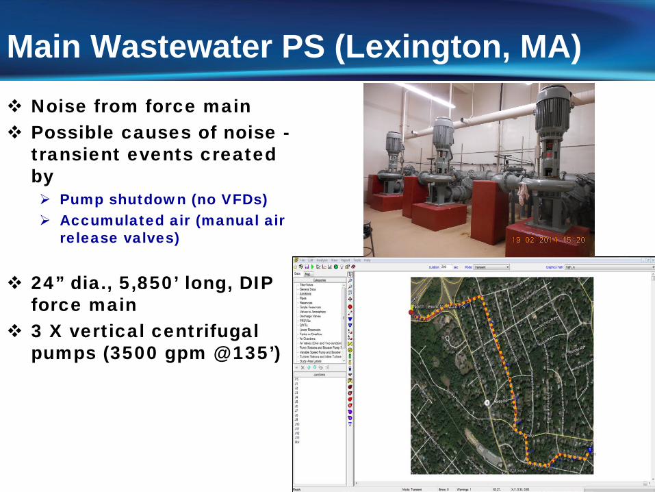
Main Wastewater PS (Lexington, MA) Noise from force main Possible causes of noise -
transient events created by Pump shutdown (no VFDs) Accumulated air (manual air
release valves)
24” dia., 5,850’ long, DIP force main
3 X vertical centrifugal pumps (3500 gpm @ 135’)
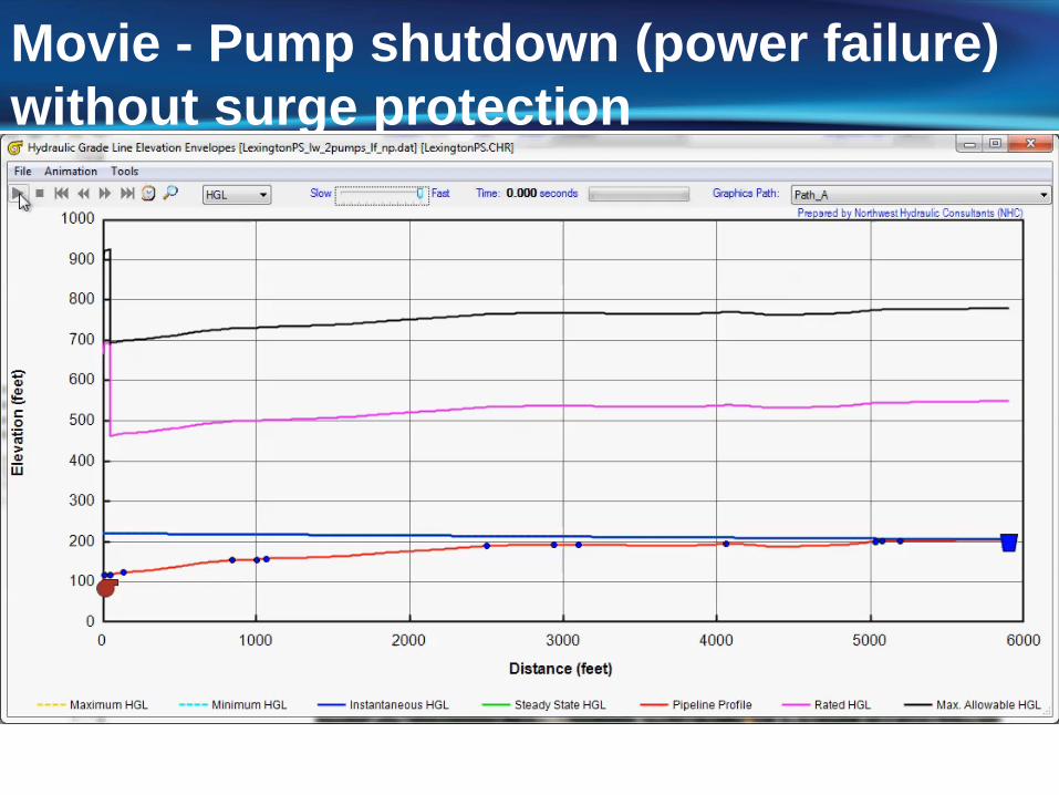
Movie - Pump shutdown (power failure) without surge protection
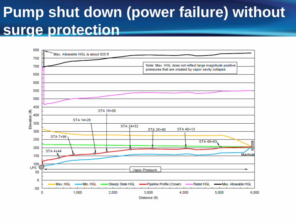
Pump shut down (power failure) without surge protection
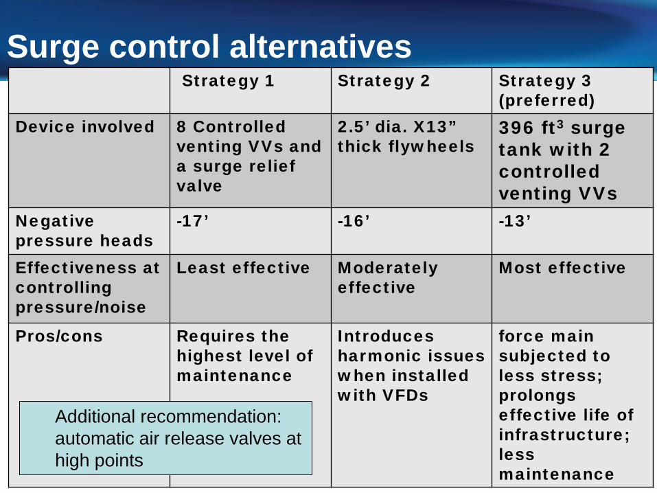
Strategy 1 Strategy 2 Strategy 3 (preferred)
Device involved 8 Controlled venting VVs and a surge relief valve
2.5’ dia. X13” thick flywheels
396 ft3 surge tank with 2 controlled venting VVs
Negative pressure heads
-17’ -16’ -13’
Effectiveness at controlling pressure/noise
Least effective Moderatelyeffective
Most effective
Pros/cons Requires the highest level of maintenance
Introduces harmonic issues when installed with VFDs
force main subjected to less stress;prolongs effective life of infrastructure;less maintenance
Surge control alternatives
Additional recommendation: automatic air release valves at high points
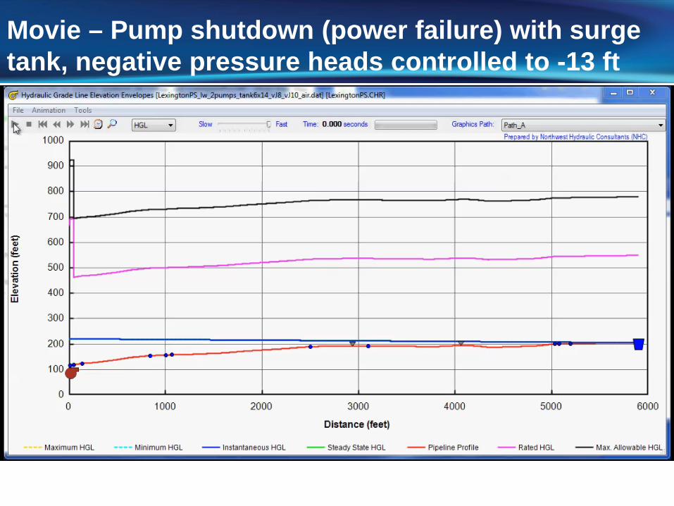
Movie – Pump shutdown (power failure) with surge tank, negative pressure heads controlled to -13 ft
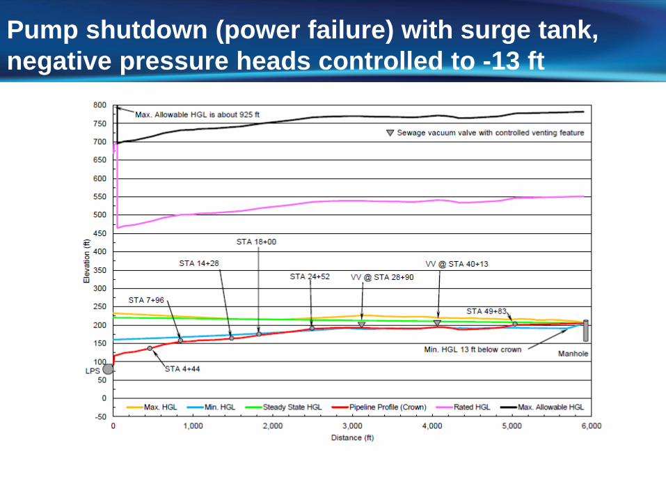
Pump shutdown (power failure) with surge tank, negative pressure heads controlled to -13 ft
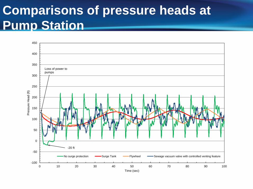
Comparisons of pressure heads at Pump Station
-100
-50
0
50
100
150
200
250
300
350
400
450
0 10 20 30 40 50 60 70 80 90 100
Pres
sure
Hea
d (ft
)
Time (sec)
No surge protection Surge Tank Flywheel Sewage vacuum valve with controlled venting feature
Loss of power to pumps
-20 ft
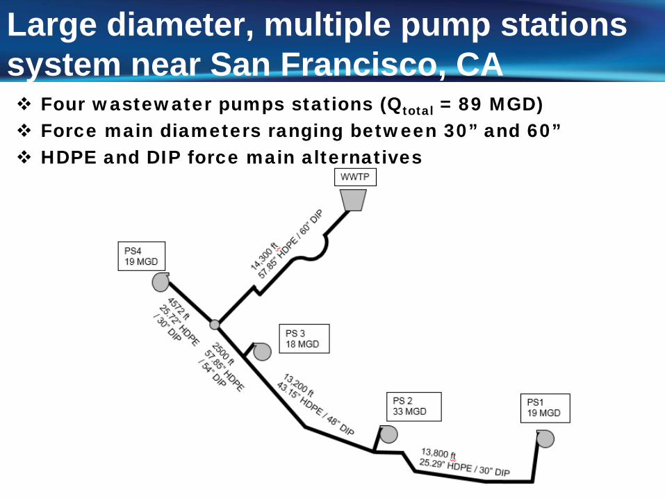
Large diameter, multiple pump stations system near San Francisco, CA Four wastewater pumps stations (Qtotal = 89 MGD) Force main diameters ranging between 30” and 60” HDPE and DIP force main alternatives
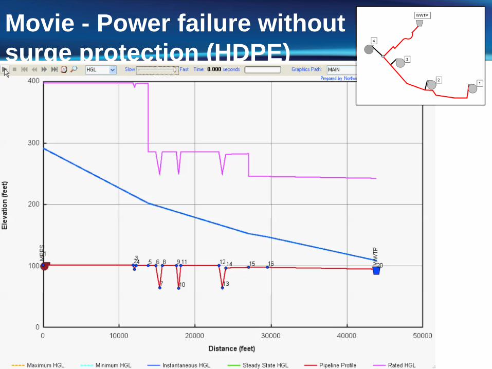
Movie - Power failure without surge protection (HDPE)
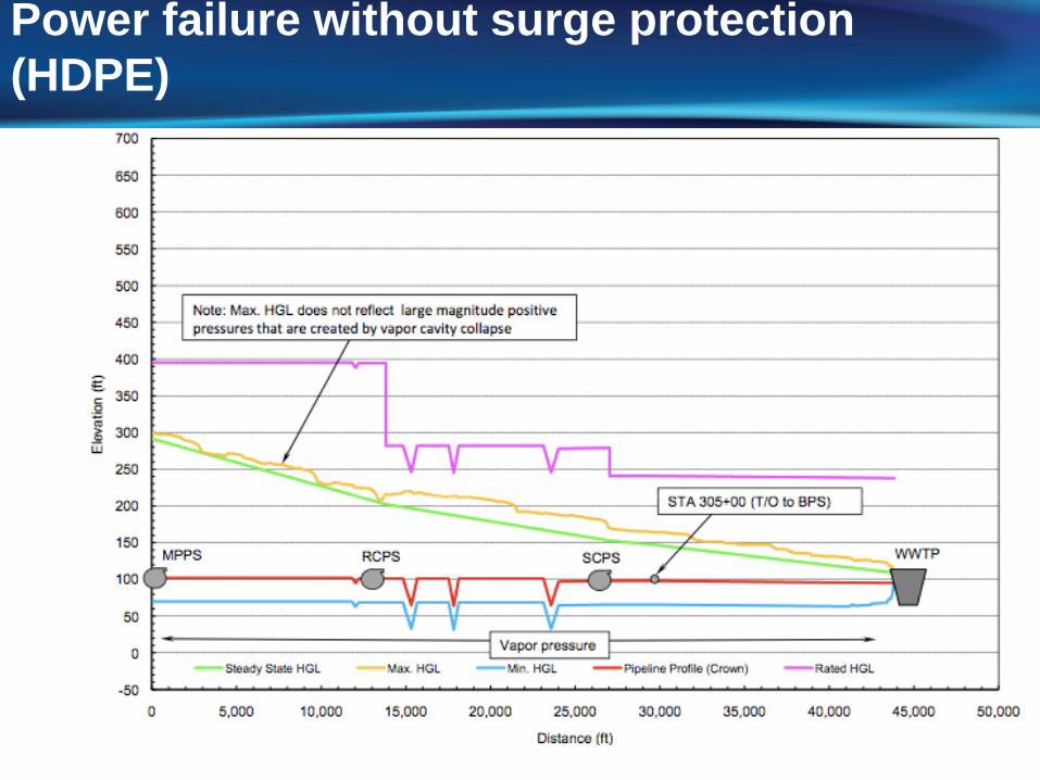
Power failure without surge protection (HDPE)
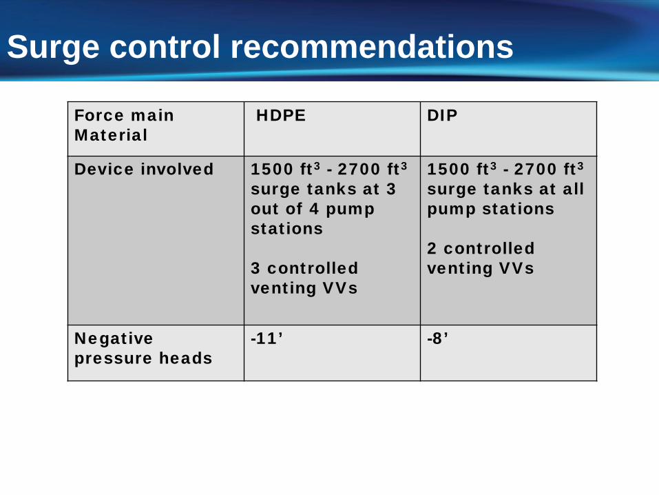
Force main Material
HDPE DIP
Device involved 1500 ft3 - 2700 ft3
surge tanks at 3 out of 4 pump stations
3 controlled venting VVs
1500 ft3 - 2700 ft3
surge tanks at all pump stations
2 controlled venting VVs
Negative pressure heads
-11’ -8’
Surge control recommendations
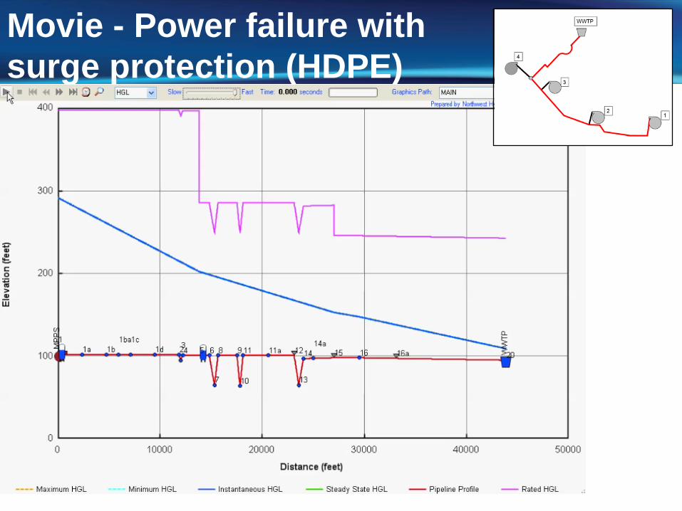
Movie - Power failure with surge protection (HDPE)
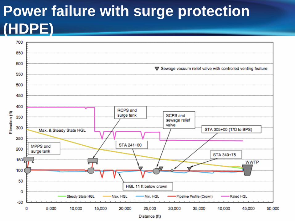
Power failure with surge protection (HDPE)
Concluding Remarks
Many surge control options available Proper selection and installation are important Surge control strategy could involve multiple
devices Surge control device can maximize effective life of
infrastructure

water resource specialists
Northwest Hydraulic Consultants80 South Lake Avenue, Suite 800Pasadena, California 91101Tel: (626) 440-0080www.nhcweb.comContact: Nami Tanaka, [email protected]
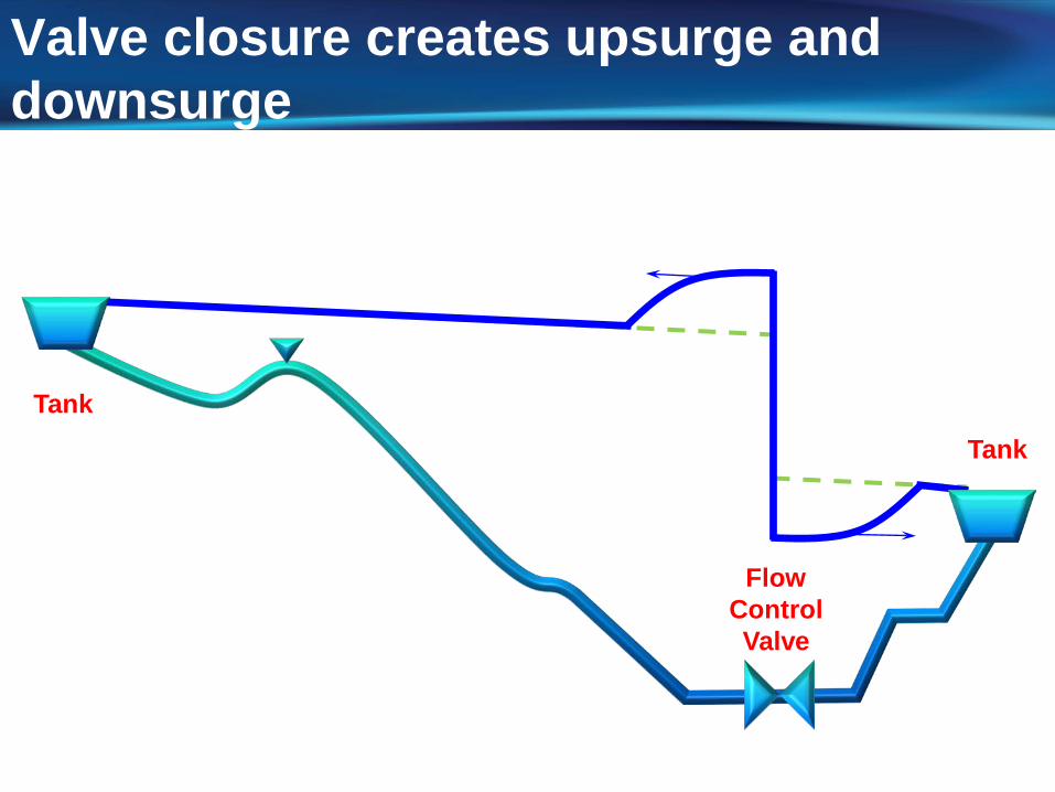
Valve closure creates upsurge and downsurge
TankTank
FlowControlValve
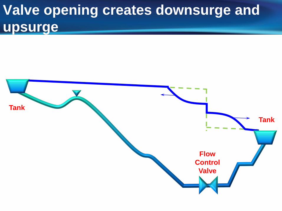
Valve opening creates downsurge and upsurge
TankTank
FlowControlValve
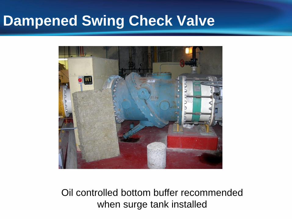
Dampened Swing Check Valve
Oil controlled bottom buffer recommendedwhen surge tank installed

Pressure Surge Analysis Computer ModelMethod of Characteristics (MOC)
Highest level of accuracy Extensively verified in lab and field Thousands of real-world systems Well suited to multi-core processors
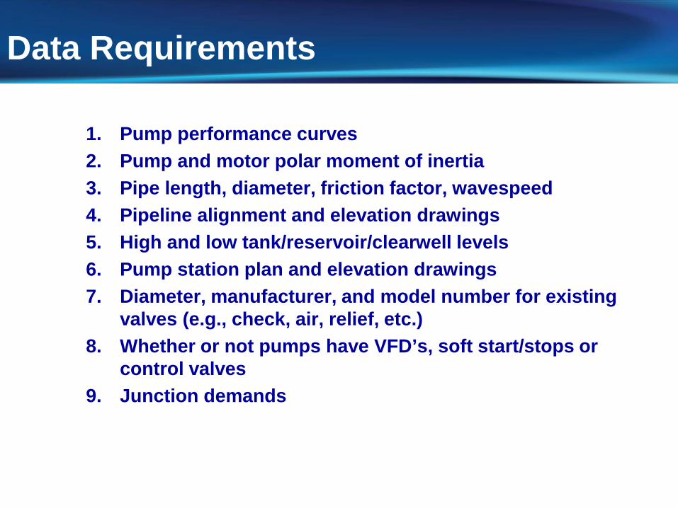
Data Requirements
1. Pump performance curves2. Pump and motor polar moment of inertia3. Pipe length, diameter, friction factor, wavespeed4. Pipeline alignment and elevation drawings5. High and low tank/reservoir/clearwell levels6. Pump station plan and elevation drawings7. Diameter, manufacturer, and model number for existing
valves (e.g., check, air, relief, etc.)8. Whether or not pumps have VFD’s, soft start/stops or
control valves9. Junction demands
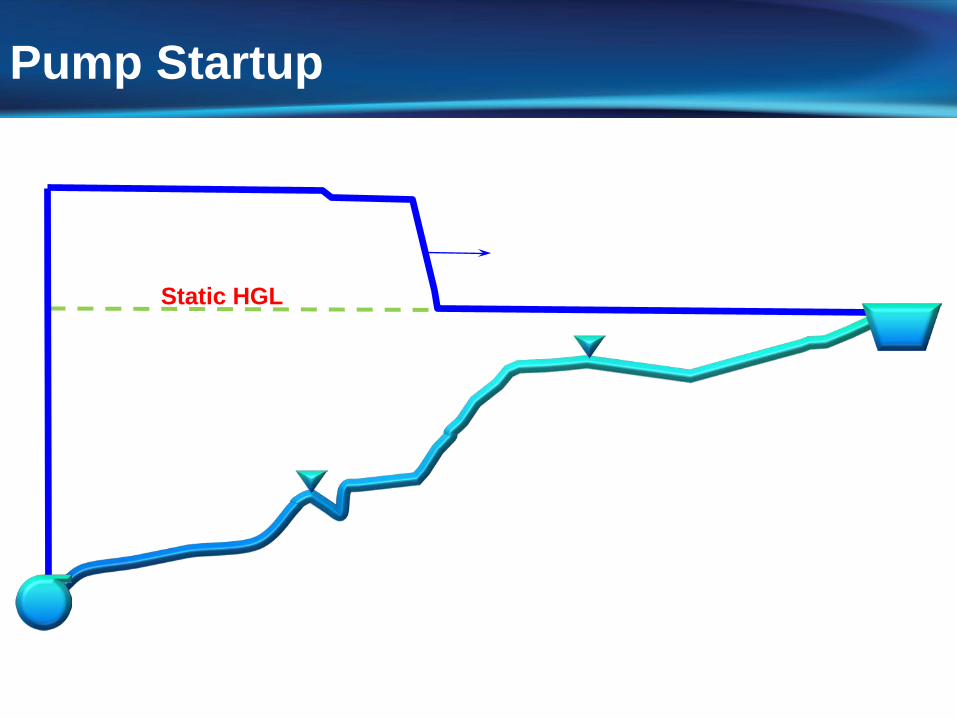
Pump Startup
Static HGL