surface stresses in coated steel surfaces—influence of a bond layer on
TRANSCRIPT
ARTICLE IN PRESS
Tribology International 42 (2009) 137– 148
Contents lists available at ScienceDirect
Tribology International
0301-67
doi:10.1
$ Pre
4–7 Sep� Corr
1000, FI
E-m
URL
journal homepage: www.elsevier.com/locate/triboint
Surface stresses in coated steel surfaces—influence of a bond layer onsurface fracture$
Kenneth Holmberg a,�, Anssi Laukkanen a, Helena Ronkainen a, Kim Wallin a,b
a VTT Technical Research Centre of Finland, P.O. Box 1000, FI-02044 VTT, Finlandb Academy of Finland, Finland
a r t i c l e i n f o
Article history:
Received 30 August 2007
Received in revised form
24 April 2008
Accepted 28 April 2008Available online 7 July 2008
Keywords:
Hard coating
Finite-element method model
Coating adhesion
9X/$ - see front matter & 2008 Elsevier Ltd. A
016/j.triboint.2008.04.013
sented at the 34th Leeds-Lyon Symposium o
tember 2007.
esponding author at: VTT Technical Researc
-02044 VTT, Finland. Tel.: +358 20 7225370;
ail address: [email protected] (K. Holm
: http://www.vtt.fi (K. Holmberg).
a b s t r a c t
Thin hard coatings in the thickness range of only a few micrometers deposited by physical vapour
deposition (PVD) on components or tools can improve the friction and wear properties by several orders
of magnitude. A 2 mm thick TiN (E ¼ 300 GPa) coating on a high-speed steel substrate with a bond layer
at the interface between the coating and the substrate was modelled by micro-level three-dimensional
finite-element method (3D FEM) in order to optimise a coated surface with regard to coating fracture.
Both compliant low modulus (E ¼ 100 GPa) and stiff high modulus (E ¼ 500 GPa) bond layers at the
coating/substrate interface of 200 and 500 nm thickness were investigated. First principal stresses were
simulated for scratch test geometry in the load range of 7.5–15 N. Very high stress concentrations of
above 5700 MPa tensile stresses were observed in the bond layer just behind the contact zone for the
stiffer bond layer. The stiff bond layer generated 5 times higher tensile stress maxima compared to the
compliant bond layer. There was approximately 3.5 times larger strain in the compliant bond layer
compared to the stiff bond layer. The general coating design advice based on this exercise is that when a
bond layer is used e.g. for coating/substrate adhesion improvement should the bond layer be less stiff
than the coating not to generate high and critical tensile stresses. The thickness of the bond layer may
vary and is not critical with respect to generated stresses in the surface.
& 2008 Elsevier Ltd. All rights reserved.
1. Introduction
The use of surface coatings has increased tremendously inthe last two decades. Typical applications are on a variety ofmechanical components in engines and transmissions, on metal-cutting and -forming tools in the manufacturing industry, on discdrives in the computer industry, on precision instruments, and onbiomedical implants. The advanced deposition techniques, likechemical vapour deposition (CVD) and physical vapour deposition(PVD) offer a wide range of possibilities to tailor the near surfacechemistry and properties of these components to extend theirefficiency, performance and durability in actual applications.A thin ceramic coating with a thickness of some few micrometresis very often deposited with a bond layer that has the function ofimproving the coating/substrate adhesion. The thickness of the
ll rights reserved.
n Tribology, Lyon,
h Centre of Finland, P.O. Box
fax: +358 20 7227077.
berg).
bond layer is typically some few hundred nanometres or less andthe hardness and elastic properties vary largely.
The tribological contact with two surfaces loaded against eachother in relative motion is a very complex system and the systembecomes even much more complex when coatings are depositedon the surfaces [1–3]. The most relevant parameters to be used todescribe the friction and wear behaviour in coated tribologicalcontacts are not easily determined and this is also the case for thematerial parameters. The importance of expressing the materialresponse of a coated surface in its basic material parameterselasticity as elastic modulus, plasticity as hardness or yieldstrength and ductility as fracture toughness has been emphasised[4–6]. Hardness is an important material property that is widelyused and well defined by several in-depth studies in the past[7–9]. Young’s modulus is another important and well-definedmaterial property [8,10]. However, other properties that attemptto describe the failure or fracture performance, such as the coatingtoughness, fracture resistance and load-carrying capacity, are notso well defined and their role is more unclear.
Because of our limited understanding of contact phenomenathe development of new coatings and their applications has beenvery much a matter of trial and error. This approach, however, hasby no means been unsuccessful. Nonetheless, the full advantage of

ARTICLE IN PRESS
Fig. 1. The stress field in the elastoplastic coated surface resulting from a rigid
sliding sphere is a result of four loading effects: friction force, geometrical
deformations, bulk plasticity concentration and residual stresses. Illustration (a)
shows the loading effects with exaggerated dimensions and deformations and (b)
with correct dimension interrelationships.
K. Holmberg et al. / Tribology International 42 (2009) 137–148138
the possibilities offered by these new techniques requires moresystematic approaches. Work on modelling and simulation of acoated tribological contact has been reported [11–25]. Becauseof the complexity of the problem they are still restrictedto necessary simplifications of the complete problem, such asonly considering elastic or plastic material behaviour or two-dimensional calculations.
The first more comprehensive three-dimensional elastic–plastic model for presenting stress and strain conditions in atypical sliding contact with a thin hard coating was presented byHolmberg et al. [26]. We illustrated how the maximum firstprincipal stresses are generated in the tail part of the slidingdiamond sphere against TiN coated flat steel contact and how atetra-armed star-shaped stress field is generated around thecontact. The stress concentrations were in agreement with theappearance of the first angular crack in the coating observed inempirical scratch testing. A method for calculating the fracturetoughness for the coating based on scratch test measurementswas presented.
The objective of our recent research work has been to developa method for optimising the mechanical properties of a coatedsurface to be used in tribological contacts with respect tosurface fracture [26,27]. In our studies we have used the contactcondition of a sphere sliding over a surface coated with a thin hardcoating. A three-dimensional finite-element method (3D FEM)model has been developed for calculating the first principalstress, true stress, true shear and strain distributions, andparameters influencing the crack propagation in the contact ofthe spherical tip moving with increased load on a coated steelsurface. The used 3D FEM model was in our mentioned previouspapers compared with empirical observations and the correlationwas good and encouraging. The purpose of this paper is todemonstrate by stress and strain computer simulation theinfluence of bond layer thickness and stiffness on the stressconditions and fracture behaviour of a steel surface coatedwith a hard and thin ceramic coating and having a very thininterface layer between the coating and the substrate, called thebond layer.
2. Scratch testing
In this work the tribosystem of a sphere sliding on a coated flatsurface with increasing normal load was chosen to be studied.This corresponds to the contact of a spherical diamond tip slidingagainst the coated surface in a scratch tester and thus there ismuch empirical information available to compare with. Thismethod is today widely used by the coating industry and coatingdevelopment laboratories, as well as in research for evaluating thetribological properties of hard and soft coatings [28].
In the scratch testing, a diamond stylus is pulled over thecoated surface with continuously increasing normal load. Thediamond stylus is a Rockwell C diamond with a 1201 coneand a 200 mm radius spherical tip. The loading rate is normally100 N/min and the loading speed is 10 mm/min. The scratchlength is 10 mm. A preload of 5 N is used and the maximum load is50 N. The remaining groove depth and width can be measured bysurface profilometry and the information is used in the modelling.The scratch test procedure is described in more detail in theEuropean Standard prEN 1071-3 [29].
3. Contact system
A schematic representation of a spherical stylus sliding on acoated sample is shown in Fig. 1. The rigid sliding tip deforms the
surface both plastically and elastically as schematically illustratedin the figure. At the initial stage, with a light preload, a smallspherical indent is formed and the plastic material flow pushes upmaterial around the indent in a torus formed shape. As the tipmoves forward a groove with increasing depth is formed. Underthe tip both plastic and elastic deformation occurs and behind thetip only the plastic deformation prevails in the surface. Anothertorus shape is formed in front of the tip.
The stress field in the coated surface is formed as a result of thefollowing four effects [26]. The friction force between the slidingtip and the surface creates compressive stresses by the pushingforce in front of the tip and tensile stresses by the pulling forcebehind the tip. The elastoplastic response produces sphericalindent, groove and torus-shaped deformations on the surfaceduring scratching. The deformations result in bending of thecoating as shown in Fig. 1 and both compressive and tensilestresses are generated. The spherical indentation pattern causesthe substrate to deform plastically, reaching its peak value at anangle of about 451 from the plane of symmetry in the plane of thecoating. It is very common, especially for thin ceramic coatings,that they, due to the deposition process, contain even very highcompressive residual stresses [30].
When the rigid sphere is drawn over the surface with anincreasing normal load, a very complex and dynamic stress field isformed with stress concentrations at changing locations. For thecoated steel surfaces it typically results in coating fracture and aspalling pattern. The formation of cracks in a scratch groove hasbeen shown by several authors [29,31–33]. The cracks occurringon a flat steel surface coated with a thin ceramic coating in scratchtesting can be described as (a) angular cracks, (b) parallel cracks,(c) transverse semi-circular cracks, (d) coating chipping, (e)coating spalling, and (f) coating breakthrough.
4. Modelling a coated tribocontact
A 3D FEM was used for the calculation of first principal stressesand material strain in the system containing the coating, thebond layer and the substrate, and for identifying the stress
ARTICLE IN PRESS
Symmetry andcontinuity
Tip with r = 200µm
Linear-Elasticcoating
Elastic-Plasticsubstrate
12 mm
4 mm2 mm
Rigidtip
Slavecontactregion
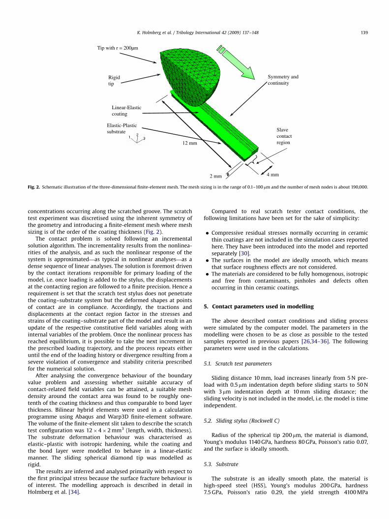
Fig. 2. Schematic illustration of the three-dimensional finite-element mesh. The mesh sizing is in the range of 0.1–100 mm and the number of mesh nodes is about 190,000.
K. Holmberg et al. / Tribology International 42 (2009) 137–148 139
concentrations occurring along the scratched groove. The scratchtest experiment was discretised using the inherent symmetry ofthe geometry and introducing a finite-element mesh where meshsizing is of the order of the coating thickness (Fig. 2).
The contact problem is solved following an incrementalsolution algorithm. The incrementality results from the nonlinea-rities of the analysis, and as such the nonlinear response of thesystem is approximated—as typical in nonlinear analyses—as adense sequence of linear analyses. The solution is foremost drivenby the contact iterations responsible for primary loading of themodel, i.e. once loading is added to the stylus, the displacementsat the contacting region are followed to a finite precision. Hence arequirement is set that the scratch test stylus does not penetratethe coating–substrate system but the deformed shapes at pointsof contact are in compliance. Accordingly, the tractions anddisplacements at the contact region factor in the stresses andstrains of the coating–substrate part of the model and result in anupdate of the respective constitutive field variables along withinternal variables of the problem. Once the nonlinear process hasreached equilibrium, it is possible to take the next increment inthe prescribed loading trajectory, and the process repeats eitheruntil the end of the loading history or divergence resulting from asevere violation of convergence and stability criteria prescribedfor the numerical solution.
After analysing the convergence behaviour of the boundaryvalue problem and assessing whether suitable accuracy ofcontact-related field variables can be attained, a suitable meshdensity around the contact area was found to be roughly one-tenth of the coating thickness and thus comparable to bond layerthickness. Bilinear hybrid elements were used in a calculationprogramme using Abaqus and Warp3D finite-element software.The volume of the finite-element slit taken to describe the scratchtest configuration was 12�4�2 mm3 (length, width, thickness).The substrate deformation behaviour was characterised aselastic–plastic with isotropic hardening, while the coating andthe bond layer were modelled to behave in a linear-elasticmanner. The sliding spherical diamond tip was modelled asrigid.
The results are inferred and analysed primarily with respect tothe first principal stress because the surface fracture behaviour isof interest. The modelling approach is described in detail inHolmberg et al. [34].
Compared to real scratch tester contact conditions, thefollowing limitations have been set for the sake of simplicity:
�
Compressive residual stresses normally occurring in ceramicthin coatings are not included in the simulation cases reportedhere. They have been introduced into the model and reportedseparately [30]. � The surfaces in the model are ideally smooth, which meansthat surface roughness effects are not considered.
� The materials are considered to be fully homogenous, isotropicand free from contaminants, pinholes and defects oftenoccurring in thin ceramic coatings.
5. Contact parameters used in modelling
The above described contact conditions and sliding processwere simulated by the computer model. The parameters in themodelling were chosen to be as close as possible to the testedsamples reported in previous papers [26,34–36]. The followingparameters were used in the calculations.
5.1. Scratch test parameters
Sliding distance 10 mm, load increases linearly from 5 N pre-load with 0.5 mm indentation depth before sliding starts to 50 Nwith 3mm indentation depth at 10 mm sliding distance; thesliding velocity is not included in the model, i.e. the model is timeindependent.
5.2. Sliding stylus (Rockwell C)
Radius of the spherical tip 200 mm, the material is diamond,Young’s modulus 1140 GPa, hardness 80 GPa, Poisson’s ratio 0.07,and the surface is ideally smooth.
5.3. Substrate
The substrate is an ideally smooth plate, the material ishigh-speed steel (HSS), Young’s modulus 200 GPa, hardness7.5 GPa, Poisson’s ratio 0.29, the yield strength 4100 MPa
ARTICLE IN PRESS
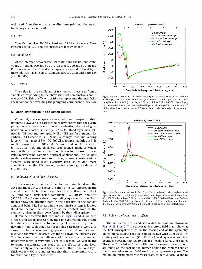
Fig. 3. Interface first principal stresses for a 2 mm TiN coated steel surface with no
bond layer, 200 nm thick compliant (E ¼ 100 GPa) bond layer, 500 nm thick
compliant (E ¼ 100 GPa) bond layer, 200 nm thick stiff (E ¼ 500 GPa) bond layer,
K. Holmberg et al. / Tribology International 42 (2009) 137–148140
estimated from the ultimate bending strength, and the strainhardening coefficient is 20.
5.4. TiN
Young’s modulus 300 GPa, hardness 27 GPa, thickness 2 mm,Poisson’s ratio 0.22, and the surface are ideally smooth.
5.5. Bond layer
At the interface between the TiN coating and the HSS substrate,Young’s modulus 100 and 500 GPa, thickness 200 and 500 nm andPoisson’s ratio 0.22. Thus do the layers correspond to bond layermaterials such as silicon or titanium (EE100 GPa) and hard TiN(EE500 GPa).
5.6. Friction
The value for the coefficient of friction was measured from asample corresponding to the above material combinations and itwas mE0.08. This coefficient of friction represents the interfacialshear component excluding the ploughing component of friction.
and 500 nm thick stiff (E ¼ 500 GPa) bond layer at a loading of 10 N as a function of
sliding direction (z) with zero at 0.014 mm behind the back edge of the contact
zone.
Fig. 4. Interface equivalent strain for a 2 mm TiN coated steel surface with no bond
layer, 200 nm thick compliant (E ¼ 100 GPa) bond layer, 500 nm thick compliant
(E ¼ 100 GPa) bond layer, 200 nm thick stiff (E ¼ 500 GPa) bond layer, and 500 nm
thick stiff (E ¼ 500 GPa) bond layer at a loading of 10 N as a function of sliding
direction (z) with zero at 0.014 mm behind the back edge of the contact zone.
6. Stress distribution in the coated contact
Commonly surface layers are referred to with respect to theirhardness. However, our earlier studies have shown that the elasticproperties are more relevant when evaluating the tribologicalbehaviour of a coated surface [26,27,34,35]. Bond layer materialsused for TiN coatings are typically Ti or TiN and for diamond-likecarbon (DLC) coatings Si. TiN has a Young’s modulus varyinglargely in the range of E ¼ 150–600 GPa, Young’s modulus of Si isin the range of E ¼ 100–180 GPa and that of Ti is aboutE ¼ 100 GPa [1,8]. The thickness and Young’s modulus valuesused in the stress simulations were chosen to be close to thesevales representing common practical applications. The Young’smodulus values were chosen so that they represent coated surfacesystems with bond layer elasticity both stiffer and morecompliant than the TiN coating, having a Young’s modulus ofE ¼ 300 GPa.
6.1. Influence of bond layer thickness
The stresses and strains in the surface were simulated with the3D FEM model. Fig. 3 shows the first principal stresses in thecentral plane of the bond layer for thin (200 nm) and thick(500 nm) bond layers being compliant (E ¼ 100 GPa) and stiff(500 GPa). Fig. 4 shows the corresponding equivalent strain. Bothfigures show the situation both in the back part of the contactzone and behind it. The zero in the coordinate system is located0.014 mm behind the back edge of the contact zone at thesymmetry plane in the groove formed by the sliding sphere.
It can be observed that the lines in Figs. 3 and 4 for bothstresses and strains representing the same Young’s modulus valuebut different thicknesses follow very close with only minordeviation from each other. Corresponding calculations were alsocarried out for the same coating system with a 100 nm thick bondlayer and the values deviated less than 5% from the 200 nm case.This indicates that the influence of thickness in the studiedparameter range is very small. For this reason, we will in thefollowing concentrate our study on the effects of bond layerstiffness only for one bond layer thickness, that is the bond layerthickness h ¼ 500 nm, and assume that this is representative alsofor other bond layer thicknesses.
6.2. Influence of bond layer stiffness
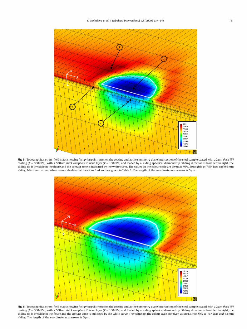
The simulated stress and strain distributions are shown inFigs. 5–13. Figs. 5–7 are topographical stress field maps showingthe first principal stresses on the coating and at the symmetryplane intersection of the steel sample coated with 2 mm thick TiNcoating with an compliant (E ¼ 100 GPa) bond layer at scratch testpositions covering the 7.5, 10 and 15 N loading range and slidingdistances from 0.6 to 2.1 mm. High tensile stress concentrationsare found on the coating top surface behind the contact zone atthe groove edge some 10–20 mm from the symmetry plane. Themaximum tensile stresses increase from 2500 to 2900 MPa and to
ARTICLE IN PRESS
Fig. 5. Topographical stress-field maps showing first principal stresses on the coating and at the symmetry plane intersection of the steel sample coated with a 2mm thick TiN
coating (E ¼ 300 GPa), with a 500 nm thick compliant Ti bond layer (E ¼ 100 GPa) and loaded by a sliding spherical diamond tip. Sliding direction is from left to right, the
sliding tip is invisible in the figure and the contact zone is indicated by the white curve. The values on the colour scale are given as MPa. Stress field at 7.5 N load and 0.6 mm
sliding. Maximum stress values were calculated at locations 1–4 and are given in Table 1. The length of the coordinate axis arrows is 5 mm.
Fig. 6. Topographical stress-field maps showing first principal stresses on the coating and at the symmetry plane intersection of the steel sample coated with a 2mm thick TiN
coating (E ¼ 300 GPa), with a 500 nm thick compliant Ti bond layer (E ¼ 100 GPa) and loaded by a sliding spherical diamond tip. Sliding direction is from left to right, the
sliding tip is invisible in the figure and the contact zone is indicated by the white curve. The values on the colour scale are given as MPa. Stress field at 10 N load and 1.2 mm
sliding. The length of the coordinate axis arrows is 5 mm.
K. Holmberg et al. / Tribology International 42 (2009) 137–148 141

ARTICLE IN PRESS
Fig. 7. Topographical stress-field maps showing first principal stresses on the coating and at the symmetry plane intersection of the steel sample coated with a 2mm thick TiN
coating (E ¼ 300 GPa), with a 500 nm thick compliant Ti bond layer (E ¼ 100 GPa) and loaded by a sliding spherical diamond tip. Sliding direction is from left to right, the
sliding tip is invisible in the figure and the contact zone is indicated by the white curve. The values on the colour scale are given as MPa. Stress field at 15 N load and 2.1 mm
sliding. The length of the coordinate axis arrows is 5 mm.
Fig. 8. Topographical stress-field maps showing first principal stresses on the coating and at the symmetry plane intersection of the steel sample coated with a 2 mm thick TiN
coating (E ¼ 300 GPa), with a 500 nm thick stiff TiN bond layer (E ¼ 500 GPa) and loaded by a sliding spherical diamond tip. Sliding direction is from left to right, the sliding
tip is invisible in the figure and the contact zone is indicated by the white curve. The values on the colour scale are given as MPa. Stress field at 7.5 N load and 0.6 mm sliding.
The length of the coordinate axis arrows is 5 mm.
K. Holmberg et al. / Tribology International 42 (2009) 137–148142
ARTICLE IN PRESS
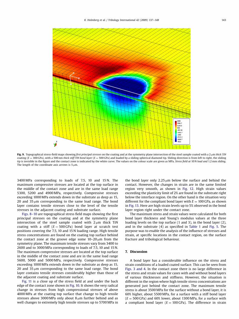
Fig. 9. Topographical stress-field maps showing first principal stresses on the coating and at the symmetry plane intersection of the steel sample coated with a 2mm thick TiN
coating (E ¼ 300 GPa), with a 500 nm thick stiff TiN bond layer (E ¼ 500 GPa) and loaded by a sliding spherical diamond tip. Sliding direction is from left to right, the sliding
tip is invisible in the figure and the contact zone is indicated by the white curve. The values on the colour scale are given as MPa. Stress field at 10 N load and 1.2 mm sliding.
The length of the coordinate axis arrows is 5 mm.
K. Holmberg et al. / Tribology International 42 (2009) 137–148 143
3400 MPa corresponding to loads of 7.5, 10 and 15 N. Themaximum compressive stresses are located at the top surface inthe middle of the contact zone and are in the same load range5300, 5200 and 4900 MPa, respectively. Compressive stressesexceeding 1000 MPa extends down in the substrate as deep as 15,20 and 35 mm corresponding to the same load range. The bondlayer contains tensile stresses close to the level of the tensilestresses in the adjacent coating and substrate surface.
Figs. 8–10 are topographical stress field maps showing the firstprincipal stresses on the coating and at the symmetry planeintersection of the steel sample coated with 2mm thick TiNcoating with a stiff (E ¼ 500 GPa) bond layer at scratch testpositions covering the 7.5, 10 and 15 N loading range. High tensilestress concentrations are found on the coating top surface behindthe contact zone at the groove edge some 10–20 mm from thesymmetry plane. The maximum tensile stresses vary from 3400 to2600 and to 3000 MPa corresponding to loads of 7.5, 10 and 15 N.The maximum compressive stresses are located at the top surfacein the middle of the contact zone and are in the same load range5600, 5000 and 5000 MPa, respectively. Compressive stressesexceeding 1000 MPa extends down in the substrate as deep as 15,20 and 35 mm corresponding to the same load range. The bondlayer contains tensile stresses considerably higher than those ofthe adjacent coating and substrate surface.
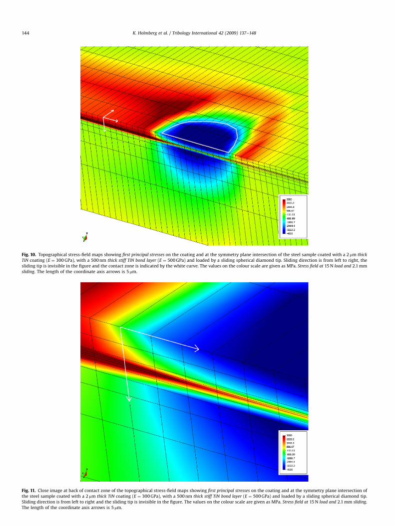
Fig. 11 is a close up of the stress field at and under the backedge of the contact zone shown in Fig. 10. It shows the very radicalchange in stresses from high compressional stresses of above4000 MPa at the coating top surface that change to high tensilestresses above 3000 MPa only about 8mm further behind and aswell changes to extremely high tensile stresses up to 5700 MPa in
the bond layer only 2.25 mm below the surface and behind thecontact. However, the changes in strain are in the same limitedregion very smooth, as shown in Fig. 12. High strain valuesexceeding the plasticity limit of 2% are found in the substrate rightbelow the interface region. On the other hand is the situation verydifferent for the compliant bond layer with E ¼ 100 GPa, as shownin Fig. 13. Here are high strain levels up to 5% observed in the bondlayer region right under the contact zone.
The maximum stress and strain values were calculated for bothbond layer thickness and Young’s modulus values at the threeloading levels on the top surface (1 and 3), in the bond layer (2),and in the substrate (4) as specified in Table 1 and Fig. 5. Thepurpose was to enable the analysis of the influence of stresses andstrain, at specific locations in the contact region, on the surfacefracture and tribological behaviour.
7. Discussion
A bond layer has a considerable influence on the stress andstrain conditions of a loaded coated surface. This can be seen fromFigs. 3 and 4. In the contact zone there is no large difference inthe stress and strain values for cases with and without bond layersof various thicknesses and stiffness. However, the situation isdifferent in the region where high tensile stress concentrations aregenerated just behind the contact zone. The maximum tensilestress is about 3500 MPa for the surface without a bond layer, it is60% higher, about 5500 MPa, for a surface with a stiff bond layer(E ¼ 500 GPa) and 60% lower, about 1300 MPa, for a surface witha compliant bond layer (E ¼ 100 GPa). The difference in strain
ARTICLE IN PRESS
Fig. 10. Topographical stress-field maps showing first principal stresses on the coating and at the symmetry plane intersection of the steel sample coated with a 2 mm thick
TiN coating (E ¼ 300 GPa), with a 500 nm thick stiff TiN bond layer (E ¼ 500 GPa) and loaded by a sliding spherical diamond tip. Sliding direction is from left to right, the
sliding tip is invisible in the figure and the contact zone is indicated by the white curve. The values on the colour scale are given as MPa. Stress field at 15 N load and 2.1 mm
sliding. The length of the coordinate axis arrows is 5 mm.
Fig. 11. Close image at back of contact zone of the topographical stress-field maps showing first principal stresses on the coating and at the symmetry plane intersection of
the steel sample coated with a 2 mm thick TiN coating (E ¼ 300 GPa), with a 500 nm thick stiff TiN bond layer (E ¼ 500 GPa) and loaded by a sliding spherical diamond tip.
Sliding direction is from left to right and the sliding tip is invisible in the figure. The values on the colour scale are given as MPa. Stress field at 15 N load and 2.1 mm sliding.
The length of the coordinate axis arrows is 5 mm.
K. Holmberg et al. / Tribology International 42 (2009) 137–148144

ARTICLE IN PRESS
Fig. 12. Topographical stress-field maps showing material strain on the coating and at the symmetry plane intersection of the steel sample coated with a 2 mm thick TiN
coating (E ¼ 300 GPa), with a 500 nm thick stiff TiN bond layer (E ¼ 500 GPa) and loaded by a sliding spherical diamond tip. Sliding direction is from left to right and the
sliding tip is invisible in the figure. The values on the colour scale are given as MPa. Stress field at 15 N load and 2.1 mm sliding. The length of the coordinate axis arrows is
5 mm.
K. Holmberg et al. / Tribology International 42 (2009) 137–148 145
values for the no bond layer and the stiff bond layer is not verybig, as shown in Fig. 4. But the strain in the compliant bond layeris considerably higher, because now the bond layer elasticityis accommodating the deformations generated by the surfaceloading.
The stress calculations showed that the influence of bond layerthickness is very small in the studied thickness range, which isrepresentative for a large range of coated surface applications. Thedeviation in first principal stress values between a 200 and a500 nm thick bond layer in the contact zone and behind it is lessthan 5%, as shown in Fig. 3. The advantage of a thick andcompliant bond layer and the disadvantage of a thick and stiffbond layer in stress accommodation about 0.01 mm behind thecontact can be seen from the deviations between the thin andthick layer curves in the far left of Fig. 3. Fig. 4 shows that also thedeviation in the strain values is as well very low, less than 5%.
The general stress pattern in the coated surface is very similarto that earlier reported for similar contacts but without bondlayers [26,34]. There is a concentration of high tensile stresses atthe coating top surface right behind the contact zone at the edgeof the formed groove. It has earlier been shown that this stressmaxima correlate with the place where the first angular cracks areformed in the coating [26]. There are some high tensile stressregions right in front of the sliding stylus generated from thebuckling effect. Very high compressional stresses are generated inthe contact zone under the stylus.
In the case with a compliant bond layer, Figs. 5–7, it can beseen that there are no big changes in the stress level in the regionsadjacent to the bond layer and in the bond layer. The bond layerstretches according to the loading conditions and this results in
considerable changes in strain. These high strain levels in thebond layer can be seen in Fig. 13. The situation is different for acoated surface with a stiff bond layer, as shown in Figs. 8–10. Nowthe bond layer does not have the ability to stretch andaccommodate the loading conditions. The loading results in veryhigh tensile stresses in the bond layer. The rapid change from highcompressional stresses in the contact region to very high tensilestresses right behind the contact and in the bond layer are shownin Fig. 11. The tensile stresses in the bond layer in Fig. 11conditions were calculated to be as high as 5700 MPa.
The role of plasticity in the analyses of bond layer behaviour,particularly considering the importance of plasticity in differentlayers, can be understood by thinking of it as an additional‘‘driving force’’ for the local stresses and strains. Increased plasticdeformation forces the adjacent layers to comply to the deforma-tions of the more compliant layers, and hence can lead to anincrease in local stresses in layers next to a more compliant layer.Vice versa, stiffer layers increase the overall magnitude of thestress state, and for layers unable to respond to the increase oflocal stresses they have to comply by producing higher plasticstrains. This behaviour was illustrated by the analysis casesfocusing on two principally different layers, a compliant one and astiff one. The coating layers were considered elastic, and there arecases where the behaviour of the bond layer in particular wouldbe more complex than that, and especially one exhibitingelastic–plastic properties. How such a system response will be,naturally, directly related to the plastic response of such a bondlayer. A plastically stiffer layer will take on the stresses andtransfer the possible additional loading, resulting from propertymismatch, to the adjacent layers, particularly to the coating, while

ARTICLE IN PRESS
Fig. 13. Topographical stress-field maps showing material strain on the coating and at the symmetry plane intersection of the steel sample coated with a 2 mm thick TiN
coating (E ¼ 300 GPa), with a 500 nm thick compliant Ti bond layer (E ¼ 100 GPa) and loaded by a sliding spherical diamond tip. Sliding direction is from left to right and the
sliding tip is invisible in the figure. The values on the colour scale are given as MPa. Stress field at 15 N load and 2.1 mm sliding. The length of the coordinate axis arrows is
5 mm.
Table 1Stresses and stain at different locations in the surface close to the contact zone when a spherical diamond tip is sliding over a 2mm TiN coated steel surface with a stiff and
compliant, thick and thin bond layer
Nor-
mal
load,
w (N)
Bond
layer
stiffness,
E (GPa)
Bond
layer
thick-
ness, h
(nm)
Coating
surface
max tensile
stress (1), MPa
( ¼4coating
cracking)
Bond layer, max
tensile stress
behind
contact (2), MPa
( ¼4inter-face
cracking)
Bond layer, max shear
stress behind
contact (2), MPa
( ¼4interface
delamination)
Bond layer
strain behind
contact (2)
( ¼4interface cracking)
Coating max
compressive
stress (3), MPa
( ¼4load-
carrying
capacity)
Substrate max
compressive
stress (4), MPa
( ¼4substrate
loading)
7.5 500 200 2690 3322 1716 0.014 �5519 �3693
7.5 500 500 2702 3234 1794 0.012 �5609 �37157.5 100 200 2591 654 1828 0.042 �5379 �3636
7.5 100 500 2494 654 1766 0.042 �5225 �3567
10 500 200 2938 4216 1909 0.024 �5471 �394610 500 500 3156 4303 1911 0.013 �5568 �3939
10 100 200 3038 877 1882 0.044 �5323 �3888
10 100 500 2925 872 1810 0.044 �5184 �3820
15 500 200 3628 5699 2026 0.018 �5165 �423315 500 500 3640 5597 2134 0.015 �5247 �4013
15 100 200 3483 1281 2082 0.049 �5038 �4175
15 100 500 3360 1298 1986 0.049 �4913 �4112
The locations (1)–(4) are shown in Fig. 5. The highest values are marked as bold and the lowest values as italic.
K. Holmberg et al. / Tribology International 42 (2009) 137–148146
a more compliant layer will behave like a ‘‘soft’’ substrate. In sucha case the bond layer is unable to respond to the behaviour ofthe coating and the substrate without developing intense localstrains acting like a membrane, which could be considered aprecursor to local collapse like failure of such a layer rather thantensile cracking of stiffer like layers.
The mechanisms by which the surface stresses influence on thefracture and tribological behaviour of a coated surface are verycomplex. In order to study some of these mechanisms andhow they are influenced by a bond layer were the followingmechanisms identified at different locations in the contact region,see Fig. 5, and the maximum stress values and some strain values

ARTICLE IN PRESS
K. Holmberg et al. / Tribology International 42 (2009) 137–148 147
calculated. In Table 1 are the maximum values in each loadingregion marked as bold and the minimum values marked as italic.The identified mechanisms at different locations are:
1.
Location 1: Cracking of the coating is strongly influenced bythe tensile stress concentrations on the top surface of thecoating. Coating cracking is often the origin of coating failure.Highest tensile stress values occurred for the coating with astiff and thick bond layer. The corresponding values for thecoating with a compliant and thin bond layer were about 7%lower.2.
Location 2: Cracking at the coating/substrate interface orwithin the bond layer is strongly influenced by the tensileand shear stresses in the interface layer region. The strain inthis region reflects the level of deformation accommodated.Failure in this region results easily in coating delamination. Thethickness of the bond layer influences tensile stresses in thebond layer only slightly, less than 3%, and as well the shearstresses not more than 6%. However, the influence of the bondlayer stiffness is considerable. The stiff bond layer generated 5times higher tensile stress maxima (3234–5699 MPa) com-pared to the compliant bond layer (654–1298 MPa) but theinfluence on the shear stresses was low, less than 8%. Therewas no influence of bond layer thickness on strain withcompliant bond layers. For the stiff bond layers the strain was16–100% higher for the thin bond layer compared to the thickone. There was about 3.5 times larger strain in the compliantbond layer compared to the stiff one.3.
Location 3: The coated surface load-carrying capacity isreflected by the level of compression at the coating top surfacejust under the sliding stylus. With a poor load-carryingcapacity the system will deflect due to elastic and plasticdeformation and also causes higher ploughing friction. A highload-carrying capacity is characterised by high surface com-pressional stress, which on the other hand may be critical forfracture. The influence of bond layer thickness on maximumcompressive stresses at the top of the coating in the middle ofthe contact zone was very small, less than 3%. The compressivestresses were 6–7.5% higher for the stiff bond layer case thanfor the compliant bond layer.4.
Location 4: Substrate loading is influenced by the compres-sional stresses under the contact zone and may be critical forhow high loading the substrate material can take withoutfailure. The influence of bond layer thickness on maximumcompressive stresses in the substrate was very small, less than6%. The compressive stresses were 3–4% higher for the stiffbond layer case than for the compliant bond layer.A compliant bond layer is more beneficial than a stiff bond layer.With respect to the coating top surface stresses the effect is notvery large, it has lower maximum stresses of about 7%. However, acompliant bond layer will considerably decrease the stresseswithin the interface layer region. On the other hand, a stiffinterface layer will generate very high interface stresses. Highinterface stresses correspond to low strain and vice versa. Acompliant bond layer results in slightly lower compressionalstresses both in the substrate below the coating and at the coatingtop surface in the contact region due to the higher elasticity of thecomplete system. For a stiff bond layer the compressional stressesare slightly higher.
8. Conclusions
The conditions when a rigid sphere is sliding with increasingload over a steel surface coated with a thin ceramic coating
(E ¼ 300 GPa) and having a bond layer between the coatingand the substrate were studied by 3D FEM modelling andstress and strain simulations. The results gave the followingconclusions:
1.
A bond layer between the coating and the substrate has aconsiderable influence on the stress and strain conditions of aloaded coated surface.2.
The influence of bond layer thickness, when the bond layer isabout 10–25% of the coating thickness, on the generatedsurface stresses and strain is very small, less than 5%.3.
There is a concentration of high tensile stresses in the bondlayer right behind the contact zone. This maximum isconsiderably higher, up to 60% higher, with a stiff bond layer(E ¼ 500 GPa) and considerably lower, down to 60% lower, witha compliant bond layer (E ¼ 100 GPa) compared to a coatedsurface with no bond layer.4.
The stress conditions in a typical 2 mm thick TiN (E ¼ 300 GPa)coating with a 500 nm thick bond layer on a steel surfacewere analysed. A compliant bond layer accommodatedwith the loading conditions and no large stress gradientsoccurred. However, there was large strain in the bondlayer under the contact region. A stiff bond layer didnot accommodate the loading by strain but resulted inextremely high tensile stresses in the bond layer, up to5700 MPa.5.
The bond layer thickness and stiffness have only a slightinfluence on the surface cracking-related maximum tensilestresses in the top surface of the coating at the groove edgebehind the sliding tip, less than 7%; it also has only a slightinfluence on the load-carrying capacity-related maximumcompressional stresses at the top of the coating in the contactregion, less than 8%; and it has as well only a slight influenceon the substrate loading-related compressional stresses in thesubstrate, less than 6%.6.
The bond layer stiffness influences considerably on the tensilestresses and strain in the bond layer at the interface betweenthe coating and the substrate just behind the back edgeof the contact zone that are related to coating delamination.The stiff bond layer generated 5 times higher tensile stressmaxima (3234–5699 MPa) than the compliant bond layer(654–1298 MPa). By contrast, the elastic strain in the compli-ant bond layer was approximately 3.5 times larger than for thestiff bond layer.7.
The general coating design advice based on this exercise isthat when a bond layer is used e.g. for coating/substrateadhesion improvement should the bond layer be lessstiff than the coating so as not to generate high and criticaltensile stresses. The thickness of the bond layer may varyand is not critical with respect to generated stresses in thesurface.Acknowledgements
The authors want to acknowledge the following colleagues forinteresting and valuable discussions in relation to the work: AliErdemir, Argonne National Laboratory, USA; Sture Hogmark,Uppsala University, Sweden; Philippe Kapsa, Ecole Central deLyon, France; Henry Haefke and Imad Ahmed, CSEM, Switzerland;Koij Kato, Tohoku University, Japan; and Kaj Pischow and RosaAimo, Savcor Coatings, Finland.
The financial support of TEKES the Finnish Technology Agency;Taiho Kogyo Tribology Research Foundation, Japan; Savcor Coat-ings, Finland; and the VTT Technical Research Centre of Finland isgratefully acknowledged.

ARTICLE IN PRESS
K. Holmberg et al. / Tribology International 42 (2009) 137–148148
References
[1] Holmberg K, Matthews A. Coatings tribology properties, techniques andapplications in surface engineering, Elsevier tribology series, vol. 28. TheNetherlands: Elsevier Science B.V.; 1994. p. 442.
[2] Holmberg K, Matthews A. Triboogy of engineering surfaces. In: StanchowiakG, editor. Wear-materials, mechanisms and practice; tribology in practiceseries. Chichister, UK: Wiley; 2005. p. 123–66.
[3] Holmberg K, Ronkainen H, Laukkanen A, Wallin K. Friction and wear ofcoated surfaces—scales, modelling and simulation of tribomechanisms. SurfCoatings Technol 2007;202:1034–49.
[4] Diao D, Kato K, Hayashi K. The maximum tensile stress on a hard coatingunder sliding friction. Tribol Int 1994;27(4):267–72.
[5] Parr G. Measurement of mechanical properties by ultra-low load indentation.Mater Sci Eng A 1998;253:151–9.
[6] Holmberg K. The basic material parameters that control friction and wear ofcoated surfaces under sliding. Tribol Finnish J Tribol 2003;19(3):3–18.
[7] Burnett P, Rickerby D. The mechanical properties of wear-resistant coatings I:modelling of hardness behaviour. Thin Solid Films 1987;148:41–50.
[8] Rickerby D, Matthews D, editors. Advanced surface coatings: a handbook ofsurface engineering. Glasgow, UK: Blackie; 1991. p. 364.
[9] Ye N, Komvopoulus K. Indentation analysis of elastic–plastic homogeneousand layered media: criteria for determining the real material hardness.J Tribol Trans ASME 2003;125:685–91.
[10] Oliver W, Pharr G. An improved technique for determining hardness andelastic modulus using load and displacement sensing indentation experi-ments. J Mater Res 1992;7(6):1564–83.
[11] Komvopoulos K. Elastic–plastic finite element analysis of indented layeredmedia. J Tribol Trans ASME 1989;111:430–9.
[12] Djabella H, Arnell R. Finite element analysis of the contact stresses in anelastic coating on an elastic substrate. Thin Solid Films 1992;213:205–19.
[13] Djabella H, Arnell R. Finite element analysis of contact stresses in elasticdouble-layer systems under normal load. Thin Solid Films 1993;223:98–108.
[14] Mao K, Sun Y, Bell T. A numerical model for the dry sliding contact of layeredelastic bodies with rough surfaces. Tribol Trans 1995;39(2):416–24.
[15] Zheng L, Ramalingam S. Stresses in a coated solid due to shear and normalboundary tractions. J Vac Sci Technol A 1995;13(5):2390–8.
[16] Kral E, Komvopoulos K. Three-dimensional finite element analysis of surfacedeformation and stresses in an elastic–plastic layered medium subject toindentation and sliding contact loading. J Appl Mech Trans ASME 1996;63:365–75.
[17] Stephens L, Liu Y, Meletis E. Finite element analysis of the initial yieldingbehaviour of a hard coating/substrate system with functionally gradedinterface under indentation and friction. J Tribol Trans ASME 2000;122:381–7.
[18] Souza R, Mustoe G, Moore J. Finite element modelling of the stresses, fractureand delamination during the indentation of hard elastic films on elastic–plastic soft substrates. Thin Solid Films 2001;392:65–74.
[19] Gong Z, Komvopoulos K. Effect of surface patterning on contact deformationof elastic–plastic layered media. J Tribol Trans ASME 2003;125:16–24.
[20] Gong Z, Komvopoulos K. Mechanical and thermomechanical elastic–plasticcontact analysis of layered media with patterned surfaces. J Tribol TransASME 2004;126:9–17.
[21] Ye N, Komvopoulus K. Effect of residual stress in surface layer on contactdeformation of elastic–plastic layered media. J Tribol Trans ASME 2003;125:692–9.
[22] Ye N, Komvopoulus K. Three-dimensional finite element analysis ofelastic–plastic layered media under thermomechanical surface loading.J Tribol Trans ASME 2003;125:52–9.
[23] Gong ZG, Komvopoulos K. Surface cracking in elastic–plastic multi-layeredmedia due to repeated sliding contact. J Tribol Trans ASME 2004;126:655–63.
[24] Li J, Beres W. Three-dimensional finite element modelling of the scratch testfor a TiN coated titanium alloy substrate. Wear 2006;260:1232–42.
[25] Panich N, Sun Y. Mechanical characterization of nanostructured TiB2 coatingsusing microscratch techniques. Tribol Int 2006;39:138–45.
[26] Holmberg K, Laukkanen A, Ronkainen H, Wallin K, Varjus S. A model forstresses, crack generation and fracture toughness calculation in scratched TiNcoated steel surfaces. Wear 2003;254:278–91.
[27] Holmberg K, Laukkanen A, Ronkainen H, Wallin K. Tribological analysis offracture conditions in thin surface coatings by 3D FEM modelling and stresssimulations. Tribol Int 2005;38:1035–49.
[28] Valli J. A review of adhesion test methods for thin hard coatings. J Vac SciTechnol A 1986;4(6):3007–14.
[29] European Standard, Advanced technical ceramics-Methods of tests forceramic coatings—part 3: determination of adhesion and other mechanicalfailure modes by scratch test, prEN1071-3 1999. p. 42.
[30] Laukkanen A, Holmberg K, Koskinen J, Ronkainen H, Wallin K, Varjus S.Tribological contact analysis of a ball sliding on a flat coated surface, part III:fracture toughness calculation and influence of residual stresses. SurfCoatings Technol 2006;200:3824–44.
[31] Bull S. Failure modes in scratch adhesion testing. Surf Coatings Technol1991;50:25–32.
[32] von Stebut J, Rezakhanlou R, Anoun K, Michel H, Gantois G. Major damagemechanisms during scratch and wear testing of hard coatings on hardsubstrates. Thin Solid Films 1989;181:555–64.
[33] Larsson M, Olsson M, Hedenquist P, Hogmark S. On the mechanism of coatingfailure as demonstrated by scratch and indentation testing of TiN and HSS.Uppsala Dr thesis by Larsson, M., No. 191/1996.
[34] Holmberg K, Laukkanen A, Ronkainen H, Wallin K, Varjus S, Koskinen J.Tribological contact analysis of a rigid ball sliding on a hard coated surface,part I: modelling stresses and strains. Surf Coatings Technol 2006;200:3793–809.
[35] Holmberg K, Laukkanen A, Ronkainen H, Wallin K, Varjus S, Koskinen J.Tribological contact analysis of a rigid ball sliding on a hard coated surface,part II: material deformations, influence of coating thickness and young’smodulus. Surf Coatings Technol 2006;200:3810–23.
[36] Ronkainen H, Laukkanen A, Holmberg K. Three dimensional stress analysis ofTiN, DLC and MoS2 coated contacts by 3D FEM modeling. In: Vizintin J,Podgornik B, Holmberg K, Ciulli E, Franek F (editors). Proc. of ECOTRIB 2007joint european conference on tribology, vol. I, 12–15 June 2007, Ljubljana,Slovenia, Slovenian Society for Tribology. p. 181–94.