surface roughness and material-removal rate with magnetorheological finishing without subsurface...
TRANSCRIPT

OPTICAL MATERIAL SCIENCE AND TECHNOLOGY
Surface roughness and material-removal rate with magnetorheological finishing withoutsubsurface damage of the surface
H. B. Chenga� and Z. J. Feng
Department of Precision Instrumentation, Tsingua University, Beijing, China
Y. W. Wang
Changchun Institute of Optics, Precision Mechanics, and Physics, Chinese Academy of Sciences,Changchun, China�Submitted November 12, 2004�Opticheski� Zhurnal, 72, 70–77 �November 2005�
A new processing technique called magnetorheological finishing �MRF� is described, based oncomputer-controlled processing of optical surfaces and combining the features of ordinary pro-cessing using free abrasive with the characteristics provided by a polishing wheel and magnetiza-tion. Based on theoretical grounds, experiments to determine the material-removal rate on a para-bolic mirror have been developed and carried out in order to clarify the influence of the controlparameters: the gap between the workpiece and the polishing wheel, the rotation rate of the pol-ishing wheel, the concentration of the volume fraction of nonmagnetic particles, and the polish-ing time. Experiments have been carried out to study the surface microstructure of the workpieceand the final surface roughness, brought from an initial rms value of 10.98 to 1.22 nm after20 min of MRF, and this is evidence that the process rapidly reaches the nanometer level. Theabsence of subsurface damage of the polished surface confirms that the MRF technique is expe-dient in practice. © 2005 Optical Society of America.
I. INTRODUCTION
Aspheric optical elements are important components ofmodern optical systems.1 There are many types of aspherics.Parabolic, ellipsoidal, etc. are ordinarily used.2 The currentlyincreasing requirements on aspheric optical elements �for ex-ample, for lithography�, along with the expansion of the ar-eas of use �conformal optics� cause an acute need for opticalfinishing methods that can be used locally for polishing as-pheric optical components of complex shape, fabricated frombrittle materials �for example, glass�.3 As a result, the fabri-cation of high-accuracy aspheric surfaces is still a laboriousprocess. After a very low-accuracy blank is made on a cutoffmachine, to obtain a component close to the desired shape, inthe classical finishing process, the experienced optician didmost of the work manually and ordinarily used a lap of ac-curate shape—a traditional rigid lap made from resin orpolyurethane.4 The pressure is thereby transferred throughthe abrasive suspension to the entire surface of the materialof the workpiece. The material is then removed by chemicaland mechanical interactions between the abrasive and theworkpiece. However, the material-removal rate is small, andtherefore high-accuracy optical elements take a long time tofabricate.5 Aspheric optical surfaces are currently ordinarilyfinished by computer-controlled polishing, using subaperturepolishers.6–8 The conventional process of finishing with freeabrasive with a controllable polishing load9 is used incomputer-controlled polishing. This is a process of attritionwith unattached abrasive in contact with two surfaces, inwhich abrasive particles �suspended in a liquid� are squeezedagainst the optical surface by means of a deformable pol-
865 J. Opt. Technol. 72 �11�, November 2005 1070-9762/2005/
isher, and material is removed as a result of a chemical-mechanical process.10 An alternative process is elastic emis-sion processing11—a float-polishing process12 withminimization of the contact area between the polisher andthe surface being processed, in which the polisher floats on alayer of liquid that contains abrasive particles. The thicknessof the liquid layer is a multiple of the diameter of the abra-sive particles,13 and the determining parameters of the pro-cess are the hydraulic pressure exerted by the polisher andthe kinetic energy of the abrasive. When the requirements onthe rms roughness of the surface are less than 1 nm, as ordi-narily imposed on supersmooth optics, the technical specifi-cations for the optical elements often exceed the possibilitiesof a commercial high-speed machine shop.14
This article presents a new technique of subaperture pol-ishing and shaping—magnetorheological finishing �MRF�,which was developed to overcome the limitations of the ex-isting MRF method, mainly used for polishing medium-orsmall-size optical elements.15 The distinguishing feature ofthe newly developed MRF system is a small polishing wheelthat rotates around its horizontal axis, while the axis itselfrotates around the center of the wheel in a horizontal plane.The wheel is mounted so as to scan the workpiece under it asa subaperture tool and is especially suitable for polishingasymmetric components, such as conformer lenses andlenses of arbitrary shape. The workpiece is mounted on arotating table with the surface to be processed upward, andthis helps to reduce the inertia of rotation when polishinglarge components. The mathematical model of optics finish-ing for the new MRF system is based on Preston’s
865110865-07$15.00 © 2005 Optical Society of America

equation,16 the features of the material-removal functionwere then modelled, and experiments were carried out toanalyze the process of polishing optical elements by theMRF method.
II. THE TECHNOLOGY OF MAGNETORHEOLOGICALFINISHING OF ASPHERIC SURFACES
In the MRF system, a magnet-thickened magnetorheo-logical �MR� liquid flows through a given restricting gapformed by the surface of the workpiece and a moving rigidwall, carrying out precision removal of the material and pol-ishing. The main advantage of MRF by comparison withconventional polishing is that the polishing tool does notwear down, since the recirculating liquid is continuallymonitored and maintained. The material-removal functiontherefore does not vary during polishing, and this makes itconvenient to control the polishing process. It is clear fromthe above description that there are two preconditions forsuccessful MRF: a suitable magnetic field gradient and thepreparation of an MR fluid with good rheology.
A. The tool for MRF and its structure
Figures 1a and 1b show the structure of a circular pol-ishing tool and the placement of the magnets on the tool thatare installed in the developed MRF system. When it is inoperation, the circular polishing tool is put into rotationaround its axis of rotation by one motor through a belt drive,and another motor simultaneously turns the polishing wheel,which has an axis that turns in the same direction. Thus,material can be removed from the surface of the workpieceby the motion of the rotation itself. On the other hand, themotion of rotation in the same direction also continuouslychanges its working orbit, and this is an innovative feature ofthe system. The magnets are distributed over both sides ofthe magnetic-shielding plate symmetrically, as shown in Fig.1b, in order that the magnetic lines cross the working gap
FIG. 1. Layouts of circular polishing tool �a� and placement of magnets �b4—workpiece, 5—magnet, 6—magnetic-shielding plate.
866 J. Opt. Technol. 72 �11�, November 2005
between the polishing wheel and the workpiece, keeping thedirection of the magnetic field gradient as perpendicular aspossible to the workpiece surface.
B. The principle of MRF and a model of it
As shown in Fig. 2, during polishing, the workpiece isimmersed in MR fluid at a fixed distance from the polishingwheel. When the MR fluid reaches the working gap betweenthe workpiece and the polishing wheel, it becomes morerigid under the action of the magnetic field gradient and isconverted into a Bingham plastic. The shear flow of the plas-tic MR fluid accordingly exerts a large pressure on part ofthe surface of the workpiece, and this causes removal ofmaterial. The section in which the removal of material occursis small because of the small diameter of the polishing wheeland is almost a point contact, which is called the polishingspot.
The mathematical model of MRF is developed on thebasis of Preston’s equation, which is generally accepted inoptical production. According to Preston, the material-removal rate is
axis of inherent rotation, 2—external axis of rotation, 3—polishing wheel,
FIG. 2. Schematic diagram of MRF. 1—polishing wheel, 2—MR fluid,3—shear flow of MR fluid, 4—workpiece.
�. 1—
866Cheng et al.
L�x,y� = KP�x,y�V�x,y� , �1�
where K is Preston’s coefficient, P is the pressure on thesurface of the workpiece in the polishing spot, and V is thespeed of the MR fluid in the polishing spot. In this model, Pis a very complicated parameter, consisting of the hydrody-namic pressure Pf and the magnetic pressure Pm. The MRfluid is incompressible, and the magnetic deformation pres-sure can be neglected, and therefore the magnetic pressure ismainly created by magnetization. From this, the expressionfor P is17
P = Pm + Pf . �2�
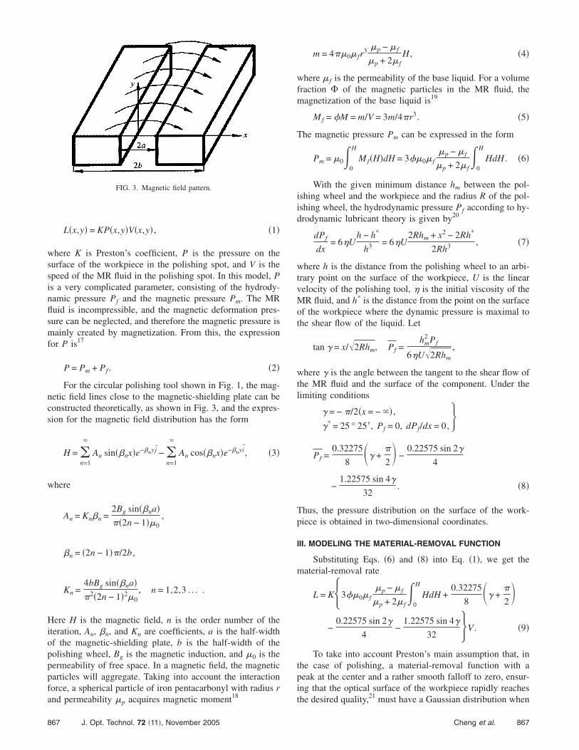
For the circular polishing tool shown in Fig. 1, the mag-netic field lines close to the magnetic-shielding plate can beconstructed theoretically, as shown in Fig. 3, and the expres-sion for the magnetic field distribution has the form
H = �n=1
�
An sin��nx�e−�nyj� − �n=1
�
An cos��nx�e−�nyi�, �3�
where
An = Kn�n =2Bg sin��na���2n − 1��0
,
�n = �2n − 1��/2b ,
Kn =4bBg sin��na��2�2n − 1�2�0
, n = 1,2,3 . . . .
Here H is the magnetic field, n is the order number of theiteration, An, �n, and Kn are coefficients, a is the half-widthof the magnetic-shielding plate, b is the half-width of thepolishing wheel, Bg is the magnetic induction, and �0 is thepermeability of free space. In a magnetic field, the magneticparticles will aggregate. Taking into account the interactionforce, a spherical particle of iron pentacarbonyl with radius rand permeability � acquires magnetic moment18
FIG. 3. Magnetic field pattern.
p
867 J. Opt. Technol. 72 �11�, November 2005
m = 4��0� fr3 �p − � f
�p + 2� fH , �4�
where � f is the permeability of the base liquid. For a volumefraction � of the magnetic particles in the MR fluid, themagnetization of the base liquid is19
Mf = �M = m/V = 3m/4�r3. �5�
The magnetic pressure Pm can be expressed in the form
Pm = �0�0
H
Mf�H�dH = 3��0� f�p − � f
�p + 2� f�
0
H
HdH . �6�
With the given minimum distance hm between the pol-ishing wheel and the workpiece and the radius R of the pol-ishing wheel, the hydrodynamic pressure Pf according to hy-drodynamic lubricant theory is given by20
dPf
dx= 6�U
h − h*
h3 = 6�U2Rhm + x2 − 2Rh*
2Rh3 , �7�
where h is the distance from the polishing wheel to an arbi-trary point on the surface of the workpiece, U is the linearvelocity of the polishing tool, � is the initial viscosity of theMR fluid, and h* is the distance from the point on the surfaceof the workpiece where the dynamic pressure is maximal tothe shear flow of the liquid. Let
tan � = x/�2Rhm, Pf =hm
2 Pf
6�U�2Rhm
,
where � is the angle between the tangent to the shear flow ofthe MR fluid and the surface of the component. Under thelimiting conditions
�� = − �/2�x = − �� ,
�* = 25 ° 25�, Pf = 0, dPf/dx = 0,�
Pf =0.32275
8�� +
�
2 −
0.22575 sin 2�
4
−1.22575 sin 4�
32. �8�
Thus, the pressure distribution on the surface of the work-piece is obtained in two-dimensional coordinates.
III. MODELING THE MATERIAL-REMOVAL FUNCTION
Substituting Eqs. �6� and �8� into Eq. �1�, we get thematerial-removal rate
L = K�3��0� f�p − � f
�p + 2� f�
0
H
HdH +0.32275
8�� +
�
2
−0.22575 sin 2�
4−
1.22575 sin 4�
32 �V . �9�
To take into account Preston’s main assumption that, inthe case of polishing, a material-removal function with apeak at the center and a rather smooth falloff to zero, ensur-ing that the optical surface of the workpiece rapidly reachesthe desired quality,21 must have a Gaussian distribution when
867Cheng et al.
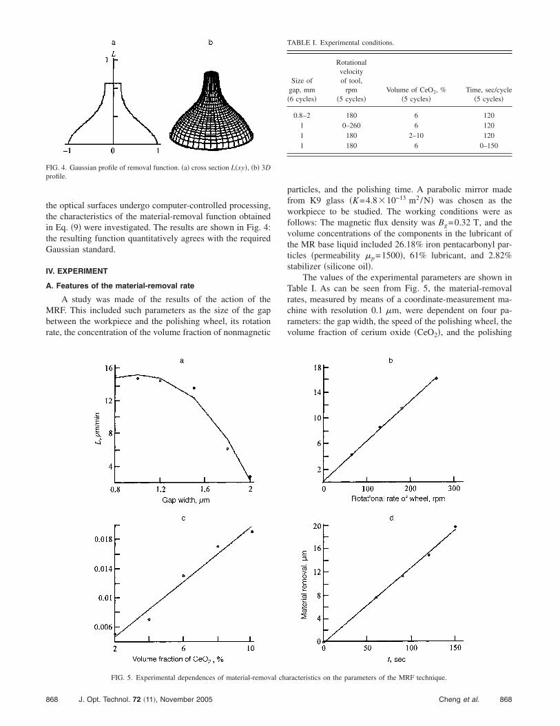
the optical surfaces undergo computer-controlled processing,the characteristics of the material-removal function obtainedin Eq. �9� were investigated. The results are shown in Fig. 4:the resulting function quantitatively agrees with the requiredGaussian standard.
IV. EXPERIMENT
A. Features of the material-removal rate
A study was made of the results of the action of theMRF. This included such parameters as the size of the gapbetween the workpiece and the polishing wheel, its rotationrate, the concentration of the volume fraction of nonmagnetic
FIG. 4. Gaussian profile of removal function. �a� cross section L�xy�, �b� 3Dprofile.
FIG. 5. Experimental dependences of material-remov
868 J. Opt. Technol. 72 �11�, November 2005
particles, and the polishing time. A parabolic mirror madefrom K9 glass �K=4.810−13 m2/N� was chosen as theworkpiece to be studied. The working conditions were asfollows: The magnetic flux density was Bg=0.32 T, and thevolume concentrations of the components in the lubricant ofthe MR base liquid included 26.18% iron pentacarbonyl par-ticles �permeability �p=1500�, 61% lubricant, and 2.82%stabilizer �silicone oil�.
The values of the experimental parameters are shown inTable I. As can be seen from Fig. 5, the material-removalrates, measured by means of a coordinate-measurement ma-chine with resolution 0.1 �m, were dependent on four pa-rameters: the gap width, the speed of the polishing wheel, thevolume fraction of cerium oxide �CeO2�, and the polishing
TABLE I. Experimental conditions.
Size ofgap, mm�6 cycles�
Rotationalvelocityof tool,
rpm�5 cycles�
Volume of CeO2, %�5 cycles�
Time, sec/cycle�5 cycles�
0.8–2 180 6 1201 0–260 6 1201 180 2–10 1201 180 6 0–150
racteristics on the parameters of the MRF technique.
al cha868Cheng et al.
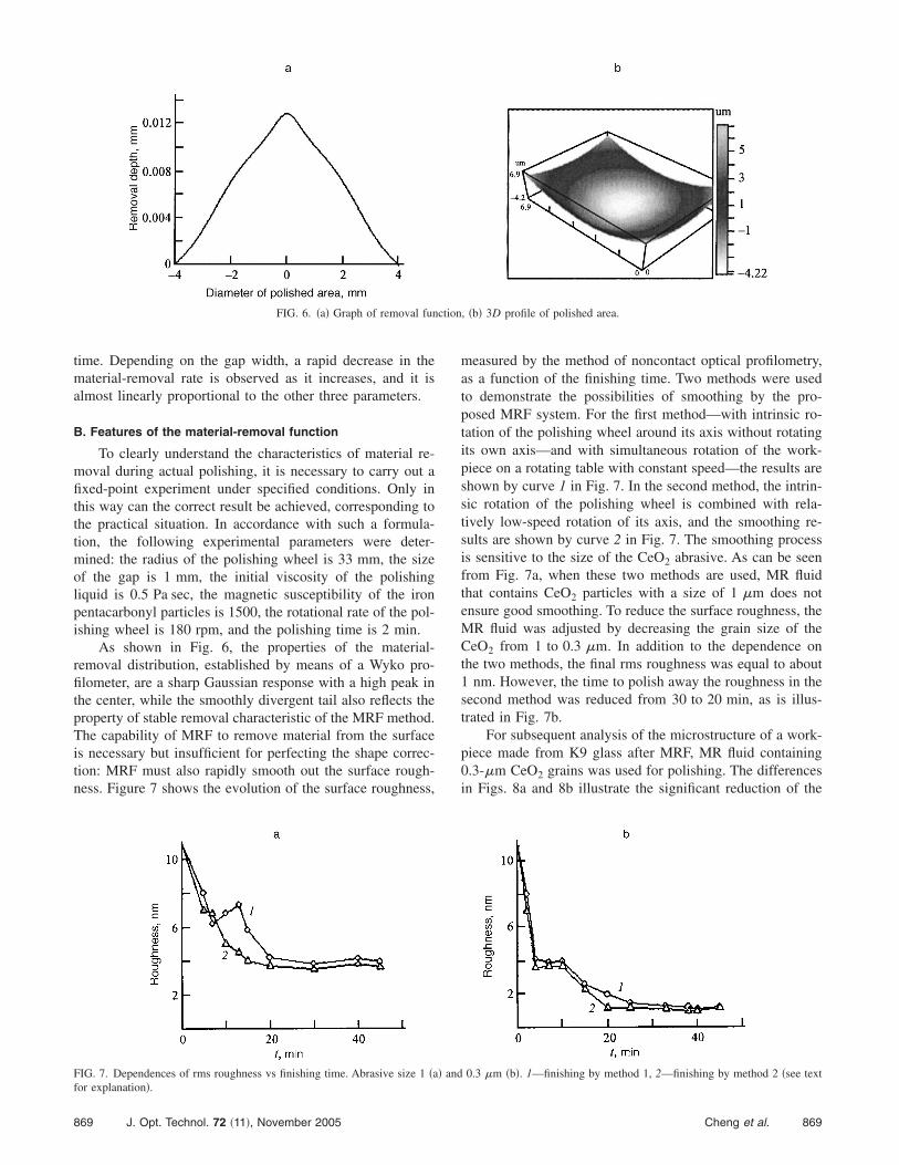
time. Depending on the gap width, a rapid decrease in thematerial-removal rate is observed as it increases, and it isalmost linearly proportional to the other three parameters.
B. Features of the material-removal function
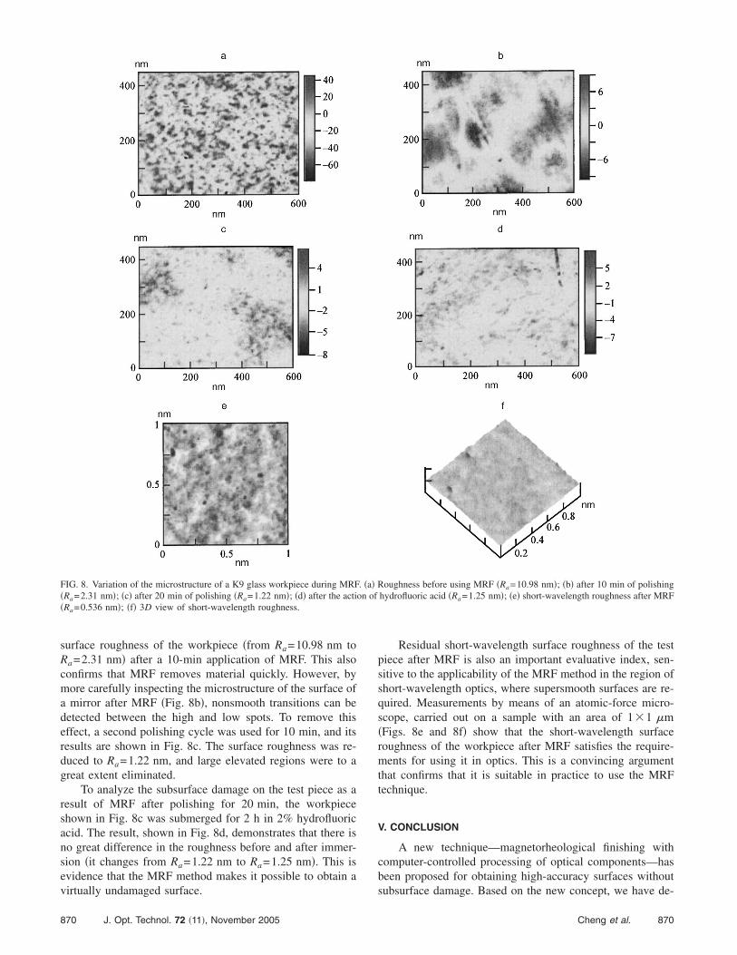
To clearly understand the characteristics of material re-moval during actual polishing, it is necessary to carry out afixed-point experiment under specified conditions. Only inthis way can the correct result be achieved, corresponding tothe practical situation. In accordance with such a formula-tion, the following experimental parameters were deter-mined: the radius of the polishing wheel is 33 mm, the sizeof the gap is 1 mm, the initial viscosity of the polishingliquid is 0.5 Pa sec, the magnetic susceptibility of the ironpentacarbonyl particles is 1500, the rotational rate of the pol-ishing wheel is 180 rpm, and the polishing time is 2 min.
As shown in Fig. 6, the properties of the material-removal distribution, established by means of a Wyko pro-filometer, are a sharp Gaussian response with a high peak inthe center, while the smoothly divergent tail also reflects theproperty of stable removal characteristic of the MRF method.The capability of MRF to remove material from the surfaceis necessary but insufficient for perfecting the shape correc-tion: MRF must also rapidly smooth out the surface rough-ness. Figure 7 shows the evolution of the surface roughness,
FIG. 6. �a� Graph of removal fun
FIG. 7. Dependences of rms roughness vs finishing time. Abrasive size 1 �afor explanation�.
869 J. Opt. Technol. 72 �11�, November 2005
measured by the method of noncontact optical profilometry,as a function of the finishing time. Two methods were usedto demonstrate the possibilities of smoothing by the pro-posed MRF system. For the first method—with intrinsic ro-tation of the polishing wheel around its axis without rotatingits own axis—and with simultaneous rotation of the work-piece on a rotating table with constant speed—the results areshown by curve 1 in Fig. 7. In the second method, the intrin-sic rotation of the polishing wheel is combined with rela-tively low-speed rotation of its axis, and the smoothing re-sults are shown by curve 2 in Fig. 7. The smoothing processis sensitive to the size of the CeO2 abrasive. As can be seenfrom Fig. 7a, when these two methods are used, MR fluidthat contains CeO2 particles with a size of 1 �m does notensure good smoothing. To reduce the surface roughness, theMR fluid was adjusted by decreasing the grain size of theCeO2 from 1 to 0.3 �m. In addition to the dependence onthe two methods, the final rms roughness was equal to about1 nm. However, the time to polish away the roughness in thesecond method was reduced from 30 to 20 min, as is illus-trated in Fig. 7b.
For subsequent analysis of the microstructure of a work-piece made from K9 glass after MRF, MR fluid containing0.3-�m CeO2 grains was used for polishing. The differencesin Figs. 8a and 8b illustrate the significant reduction of the
, �b� 3D profile of polished area.
0.3 �m �b�. 1—finishing by method 1, 2—finishing by method 2 �see text
ction
� and
869Cheng et al.
surface roughness of the workpiece �from Ra=10.98 nm toRa=2.31 nm� after a 10-min application of MRF. This alsoconfirms that MRF removes material quickly. However, bymore carefully inspecting the microstructure of the surface ofa mirror after MRF �Fig. 8b�, nonsmooth transitions can bedetected between the high and low spots. To remove thiseffect, a second polishing cycle was used for 10 min, and itsresults are shown in Fig. 8c. The surface roughness was re-duced to Ra=1.22 nm, and large elevated regions were to agreat extent eliminated.
To analyze the subsurface damage on the test piece as aresult of MRF after polishing for 20 min, the workpieceshown in Fig. 8c was submerged for 2 h in 2% hydrofluoricacid. The result, shown in Fig. 8d, demonstrates that there isno great difference in the roughness before and after immer-sion �it changes from Ra=1.22 nm to Ra=1.25 nm�. This isevidence that the MRF method makes it possible to obtain avirtually undamaged surface.
FIG. 8. Variation of the microstructure of a K9 glass workpiece during MRF�Ra=2.31 nm�; �c� after 20 min of polishing �Ra=1.22 nm�; �d� after the acti�Ra=0.536 nm�; �f� 3D view of short-wavelength roughness.
870 J. Opt. Technol. 72 �11�, November 2005
Residual short-wavelength surface roughness of the testpiece after MRF is also an important evaluative index, sen-sitive to the applicability of the MRF method in the region ofshort-wavelength optics, where supersmooth surfaces are re-quired. Measurements by means of an atomic-force micro-scope, carried out on a sample with an area of 11 �m�Figs. 8e and 8f� show that the short-wavelength surfaceroughness of the workpiece after MRF satisfies the require-ments for using it in optics. This is a convincing argumentthat confirms that it is suitable in practice to use the MRFtechnique.
V. CONCLUSION
A new technique—magnetorheological finishing withcomputer-controlled processing of optical components—hasbeen proposed for obtaining high-accuracy surfaces withoutsubsurface damage. Based on the new concept, we have de-
Roughness before using MRF �Ra=10.98 nm�; �b� after 10 min of polishinghydrofluoric acid �Ra=1.25 nm�; �e� short-wavelength roughness after MRF
. �a�on of
870Cheng et al.
veloped a new circular polishing tool. The material-removalfunction has been theoretically investigated with respect tothe influence of the process parameters, such as the hydro-dynamic and magnetic pressures. The results of modellingthe process show that the material-removal function is closeto the actual Gaussian distribution. On the basis of the result-ing theoretical prerequisites, experiments have been devel-oped and carried out to investigate the dependence of thematerial-removal rate on a parabolic mirror on such controlparameters as the size of the gap between the workpiece andthe polishing wheel, the rotational speed of the polishingwheel, the concentration of the volume fraction of magneticparticles, and the polishing time. The results showed that thematerial-removal rate depends on all the indicated param-eters. Experiments have been carried out to study the surfacemicrostructure of the workpiece after MRF. The final surfaceroughness after 20 min of MRF reached 1.22 nm when itsinitial value was 10.98 nm, with a high finishing rate to thenanometer level. These results confirm that the new MRFtechnique, with computer control of the process, is promisingfor producing high-accuracy supersmooth surfaces withoutsubsurface damage at a relatively high material-removal rate.
This work was carried out as part of the project “Studiesof a magnetorheological superprecise process of polishingaspheric lenses,” financed by the National Natural ScienceFoundation of China �Project No. 50175062�.
a�Email: [email protected], [email protected]
1R. B. Johnson, “Wide field of view three-mirror telescopes having a com-mon optical axis,” Opt. Eng. �Bellingham� 27, 1046 �1988�.
2H. B. Cheng, Z. J. Feng, and Y. B. Wu, “Fabrication of off-axis aspherical
mirrors with loose abrasive point-contact machining,” Key Eng. Mater.871 J. Opt. Technol. 72 �11�, November 2005
257–258, 153 �2004�.3W. F. Oliver, V. B. Hedser, and H. J. Frankena, “Fluid jet polishing ofoptical surfaces,” Appl. Opt. 37, 6771 �1998�.
4G. Paula, “Automating lens manufacturing,” Mech. Engin. 119, No. 3, 88�1997�.
5H. Takino, N. Shibata, and H. Itoh, “Computer numerically controlledplasma chemical vaporization machining with a pipe electrode for opticalfabrication,” Appl. Opt. 37, 5198 �1998�.
6R. A. Jones and W. J. Rupp, “Rapid optical fabrication with computercontrolled optical surfacing,” Opt. Eng. �Bellingham� 30, 1962 �1991�.
7G. Doughty and J. Smith, “Microcomputer-controlled polishing machinefor very smooth and deep aspherical surfaces,” Appl. Opt. 26, 2421�1987�.
8M. Negishi, M. Ando, and M. Takimoto, “Studies of supersmooth polish-ing on aspherical surfaces,” Int. J. Jpn. Soc. Precis. Eng. 29, 1 �1995� inJapanese�.
9N. B. Kirk and J. V. Wood, “Glass polishing,” Br. Ceram. Trans. J. 93, 25�1994�.
10H. Suzuki, S. Hara, and H. Matsunaga, “Study on aspherical surface pol-ishing using a small rotating tool-development of polishing system,” Int. J.Jpn. Soc. Precis. Eng. 59, 1713 �1993� in Japanese�.
11Y. Mori, K. Yamauchi, and K. Endo, “Elastic emission machining,” Int. J.Prec. Engin. 9, 123 �1987�.
12S. F. Soares, D. R. Baseit, and J. P. Black, “Float-polishing process andanalysis of float-polished quartz,” Appl. Opt. 33, 89 �1994�.
13Y. Mori, K. Yamauchi, and K. Endo, “Mechanism of atomic removal inelastic emission machining,” Int. J. Prec. Engin. 10, 24 �1988�.
14D. Golini, “Magnetorheological finishing automates precision optics fab-rication,” Laser Focus World 34, No. 9, 187 �1998�.
15H. M. Pollicove, “Next generation optics manufacturing technologies,”Proc. SPIE 4231, 8 �2000�.
16F. W. Preston, J. Soc. Glass Technol. 11, 214 �1927�.17W. I. Kordonski and S. D. Jacobs, “Magnetorheological finishing,” Int. J.
Mod. Phys. B 10, 2837 �1996�.18E. Lemaire, A. Menunier, and G. Bossis, “Influence of the particle size on
the rheology of magnetorheological fluids,” J. Rheol. 39, 1011 �1995�.19C. Chi, Zh. Wang, and P. Zhao, Iron Magneto-Fluid-Mechanics �Beihang
University Press, Beijing, 1993�, pp. 110–119 in Chinese�.20P. Yang, Numeric Analysis of Fluid Lubrication �National Defence Indus-
try Press, Beijing, 1998�, pp. 29–36 in Chinese�.21R. A. Jones, “Optimization of computer controlled polishing,” Appl. Opt.
16, 218 �1977�.
871Cheng et al.