surface plasmons: coating applications part 2 - svc.org · there are many more applications of the...
TRANSCRIPT
IntroductionIn Part 1[1] we looked at the fundamental conditions governing the existence of a surface plasmon polariton, that is, an electromagnetic wave, pinned to the boundary between a metal and a dielectric, associ-ated with collective oscillations of the free electrons in the metal, and with its electric and magnetic fields decaying exponentially away from the surface into both media. The phenomenon is normally known sim-ply as a surface plasmon.
We set up a right-handed set of reference axes with the x-axis along the surface in the direction of propagation of the wave, the y-axis also in the surface and the z-axis normal to it. The electric field of the wave is in the x-z plane and the magnetic field is normal to it and parallel to the surface. We recall that the wavelength associated with the sur-face plasmon is smaller than that of any free electromagnetic wave of identical frequency. This prevents direct coupling of energy from a free electromagnetic wave into a surface plasmon since the wavelength is the minimum distance between planes of equal phase. Nevertheless, it is possible by the use of a simple trick, to couple energy from a progressive wave into a surface plasmon. This opens up a range of very interesting applications involving optical coatings.
Forced OscillationsLet us start by considering a simple mechanical resonant system consist-ing of a mass retained by a spring and a viscous damper. The spring is attached both to the mass and to a solid support. The support is subject to a small vibration of variable frequency and constant amplitude. The system is sketched in Figure 1. The relative response is given by the expression
(1)
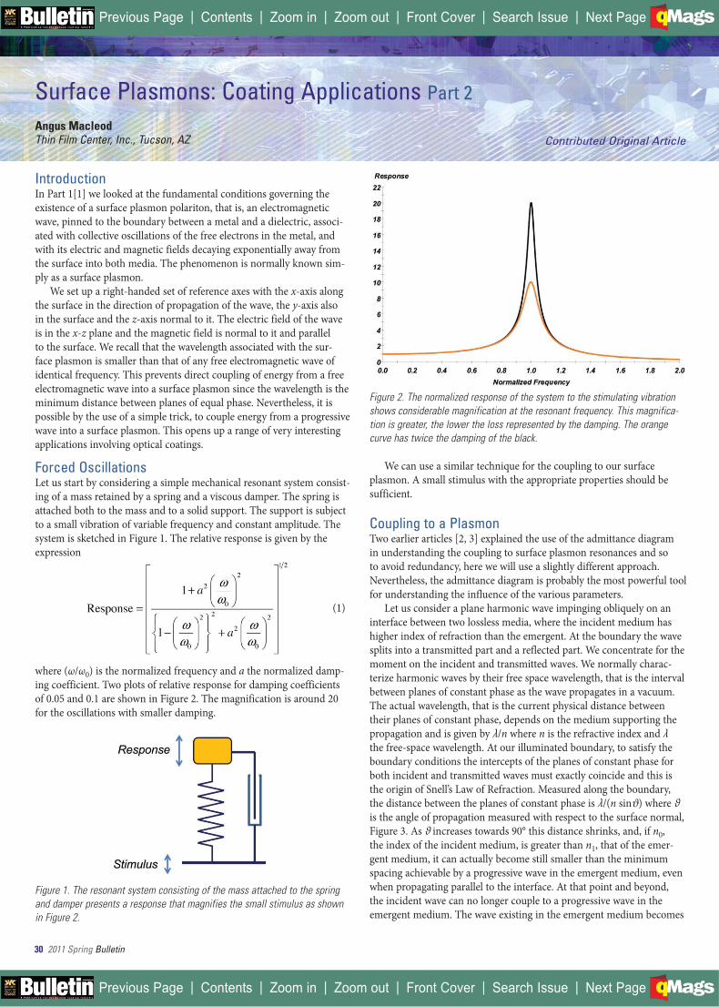
where (ω/ω0) is the normalized frequency and a the normalized damp-ing coefficient. Two plots of relative response for damping coefficients of 0.05 and 0.1 are shown in Figure 2. The magnification is around 20 for the oscillations with smaller damping.
Figure 1. The resonant system consisting of the mass attached to the spring and damper presents a response that magnifies the small stimulus as shown in Figure 2.
Figure 2. The normalized response of the system to the stimulating vibration shows considerable magnification at the resonant frequency. This magnifica-tion is greater, the lower the loss represented by the damping. The orange curve has twice the damping of the black.
We can use a similar technique for the coupling to our surface plasmon. A small stimulus with the appropriate properties should be sufficient.
Coupling to a PlasmonTwo earlier articles [2, 3] explained the use of the admittance diagram in understanding the coupling to surface plasmon resonances and so to avoid redundancy, here we will use a slightly different approach. Nevertheless, the admittance diagram is probably the most powerful tool for understanding the influence of the various parameters.
Let us consider a plane harmonic wave impinging obliquely on an interface between two lossless media, where the incident medium has higher index of refraction than the emergent. At the boundary the wave splits into a transmitted part and a reflected part. We concentrate for the moment on the incident and transmitted waves. We normally charac-terize harmonic waves by their free space wavelength, that is the interval between planes of constant phase as the wave propagates in a vacuum. The actual wavelength, that is the current physical distance between their planes of constant phase, depends on the medium supporting the propagation and is given by λ/n where n is the refractive index and λ the free-space wavelength. At our illuminated boundary, to satisfy the boundary conditions the intercepts of the planes of constant phase for both incident and transmitted waves must exactly coincide and this is the origin of Snell’s Law of Refraction. Measured along the boundary, the distance between the planes of constant phase is λ/(n sinϑ) where ϑ is the angle of propagation measured with respect to the surface normal, Figure 3. As ϑ increases towards 90° this distance shrinks, and, if n0, the index of the incident medium, is greater than n1, that of the emer-gent medium, it can actually become still smaller than the minimum spacing achievable by a progressive wave in the emergent medium, even when propagating parallel to the interface. At that point and beyond, the incident wave can no longer couple to a progressive wave in the emergent medium. The wave existing in the emergent medium becomes
Surface Plasmons: Coating Applications Part 2
Angus MacleodThin Film Center, Inc., Tucson, AZ Contributed Original Article
30 2011 Spring Bulletin
| | | | | |Previous Page Contents Zoom in Zoom out Front Cover Search Issue Next PageBA
M SaGEF
| | | | | |Previous Page Contents Zoom in Zoom out Front Cover Search Issue Next PageBA
M SaGEF

2011 Summer Bulletin 31
(10). We recall that Re(κx) is 2π/λactual and ω/c is 2π/λ where λ is the free-space wavelength. The rest is tedious algebra. All this leads to a plasmon wavelength of 612.64nm.
The exponentially decaying field on the vacuum side of the silver interface is evanescent in character, just like the wave outside our totally internally reflecting prism. Let us assume that the prism is constructed from borosilicate glass with refractive index at 632.8nm of 1.51511. To couple to the surface plasmon we need first to establish a spacing at the prism surface of 612.64nm between the planes of constant phase of the incident wave, then to arrange the surface parallel to the silver surface, and, finally, gently to move the surface into the very outer parts of the evanescent tail of the plasmon.
The angle of incidence required in the glass is given by:
(2)
and entering our values yields 42.98°. The arrangement is shown in Figure 4. We recall that the electric field of the surface plasmon was confined to the x-y plane, implying that the incident wave providing the coupling light must be p-polarized. However, at this stage we have no idea of the correct thickness of the vacuum coupling gap. The expres-sions in Part 1 allow us to calculate the rate of decay of electric field of the plasmon into the vacuum gap as 0.002570nm-1 at 632.8nm. A gap width of 900nm, therefore, will drop the field to approximately 10% of its value at the metal surface and this seems a reasonable starting com-promise between a too thin gap and too strong coupling and a too large gap with coupling that is too weak. In our derivation of the properties of a surface plasmon we used the normal electromagnetic theory apply-ing to continuous media. Our normal thin-film calculation techniques
evanescent and the incident wave is totally reflected. The fields of the evanescent wave decay exponentially away from the interface into the emergent medium.
Figure 3. The intercepts of the planes of constant phase must coincide at the interface. The propagation angles ϑ0 and ϑ1 are connected by Snell’s Law.
The clue that we have here is that the wavelength associated with the propagation of the evanescent wave parallel to the surface, is less than that of a progressive wave of identical frequency and that is a feature of our surface plasmon.
Let us assume a wavelength of 632.8nm corresponding to the red line of a HeNe laser. From Palik [4] we find the optical constants of silver at 632.8nm are 0.135-i3.987. To keep the calculations simple, we assume vacuum as the other medium. From the expressions given in Part 1[1] we can calculate the wavelength of a surface plasmon at a vacuum-silver interface at 632.8nm. The accurate expressions are in
continued on page 32
| | | | | |Previous Page Contents Zoom in Zoom out Front Cover Search Issue Next PageBA
M SaGEF
| | | | | |Previous Page Contents Zoom in Zoom out Front Cover Search Issue Next PageBA
M SaGEF
___________________
32 2011 Summer Bulletin
Surface Plasmons: Coating Applicationscontinued from page 31
should therefore be completely capable of showing the presence of a surface plasmon resonance. Such a calculation readily confirms the coupling into the p-polarized resonance by exhibiting a narrow dip in the p-reflectance of the prism, Figure 5.
Figure 4. The suggested coupling arrangement. We have just calculated the angle ϑ but the useful width of the gap between prism and metal has yet to be determined.
Figure 5. With a 900nm gap, the surface plasmon resonance shows itself as a sharp, narrow dip in reflectance for p-polarization.
Although very difficult to detect in Figure 2, the peak of the reso-nance curve shifts very slightly to lower frequencies when damping is present. This is a quite small effect but the loss in the plasmon reso-nance shifts the minimum reflectance in Figure 5 to an angle of 42.94° rather than the calculated 42.98°.
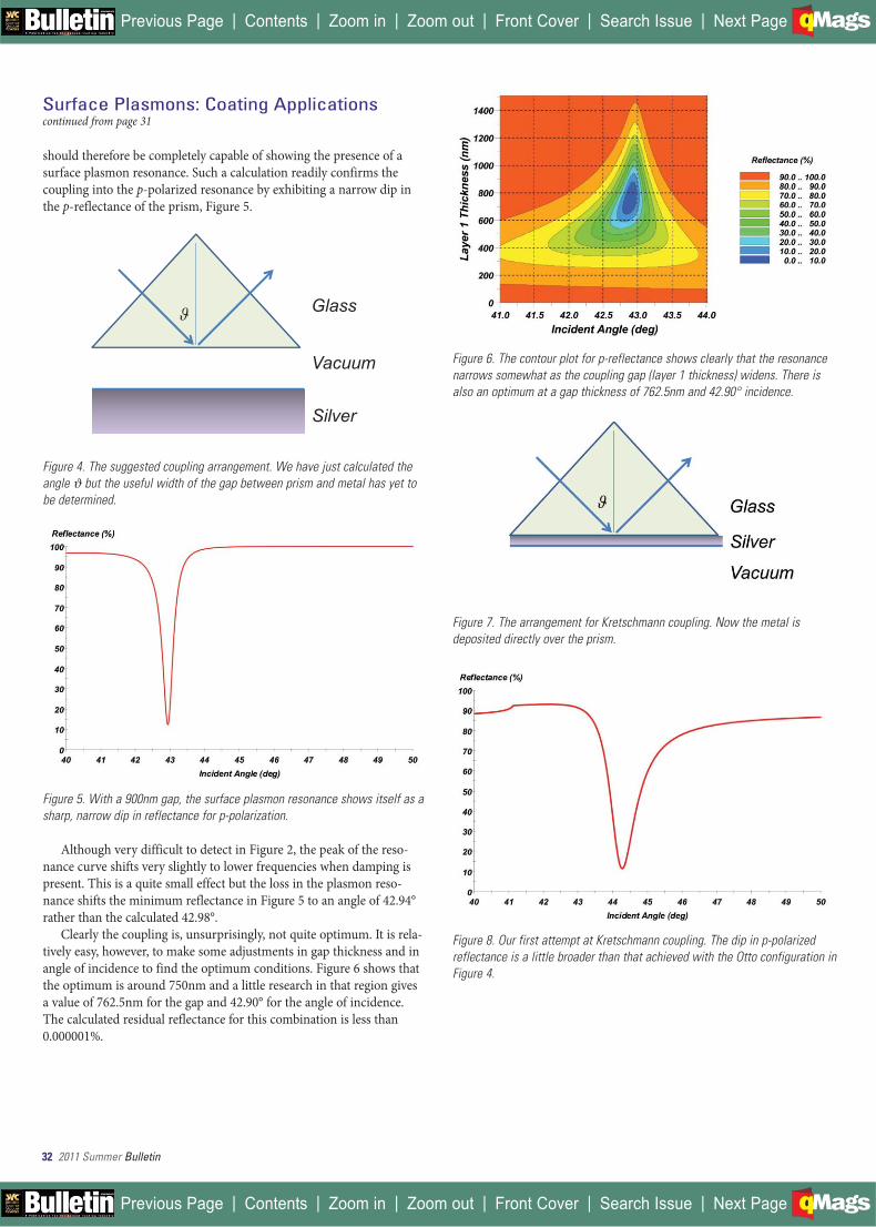
Clearly the coupling is, unsurprisingly, not quite optimum. It is rela-tively easy, however, to make some adjustments in gap thickness and in angle of incidence to find the optimum conditions. Figure 6 shows that the optimum is around 750nm and a little research in that region gives a value of 762.5nm for the gap and 42.90° for the angle of incidence. The calculated residual reflectance for this combination is less than 0.000001%.
Figure 6. The contour plot for p-reflectance shows clearly that the resonance narrows somewhat as the coupling gap (layer 1 thickness) widens. There is also an optimum at a gap thickness of 762.5nm and 42.90° incidence.
Figure 7. The arrangement for Kretschmann coupling. Now the metal is deposited directly over the prism.
Figure 8. Our first attempt at Kretschmann coupling. The dip in p-polarized reflectance is a little broader than that achieved with the Otto configuration in Figure 4.
Glass
Vacuum
Silver
| | | | | |Previous Page Contents Zoom in Zoom out Front Cover Search Issue Next PageBA
M SaGEF
| | | | | |Previous Page Contents Zoom in Zoom out Front Cover Search Issue Next PageBA
M SaGEF

2011 Summer Bulletin 33
continued on page 36
Figure 9. The contour plot showing the variation of p-reflectance with the param-eters in Kretschmann coupling, Figure 7. Layer 1 in this case is the silver layer.
The coupling arrangement in Figure 4 is generally known by the name Otto [5] from the originator of this technique. There is another similar technique that is known by the name Kretschmann [6]. In this case the coupling is through the metal that is, therefore, deposited directly on the prism surface, Figure 7. The plasmon is pinned to the outer surface of the metal. In the metal, the equations from Part 1 yield an electric field decay constant away from the surface of 0.040889nm-1. Again, permitting the field to fall to around 10% of its surface value for the coupling point, gives us a starting physical thickness of silver of 56.3nm, Figure 8. Figure 9 shows the way in which the resonance varies with the parameters of the metal film and the incident angle. The same class of search, as was carried out for the Otto technique, yields an optimum silver thickness of 46.21nm with a residual reflectance less than 0.000001% with an angle this time at 43.09°.
Sensitive Detectors
Figure 10. The input irradiance is assumed to be 1W/m2. This shows the par-allel and normal electric field amplitudes at the resonance. Note the enor-mous magnification at the surface.
The variation of electric field amplitude for the optimum conditions for the Kretschmann coupling is illustrated in Figure 10. The incident irradiance is 1W/m2. Distances are measured from the prism surface. The absence of any standing wave in the incident medium is a conse-quence of the zero reflectance. The very high field at the outer metal surface implies an enhanced sensitivity to any material that should be present there, and, of course, such interaction will go with the square of the electric field amplitude.
Let us suppose that a small amount of dielectric material is added to the outer surface of the metal. This will be of higher refractive index
| | | | | |Previous Page Contents Zoom in Zoom out Front Cover Search Issue Next PageBA
M SaGEF
| | | | | |Previous Page Contents Zoom in Zoom out Front Cover Search Issue Next PageBA
M SaGEF
__________________
_____________________________

| | | | | |Previous Page Contents Zoom in Zoom out Front Cover Search Issue Next PageBA
M SaGEF
| | | | | |Previous Page Contents Zoom in Zoom out Front Cover Search Issue Next PageBA
M SaGEF

2011 Summer Bulletin 35
| | | | | |Previous Page Contents Zoom in Zoom out Front Cover Search Issue Next PageBA
M SaGEF
| | | | | |Previous Page Contents Zoom in Zoom out Front Cover Search Issue Next PageBA
M SaGEF
______________
______________________

36 2011 Summer Bulletin
Surface Plasmons: Coating Applicationscontinued from page 33
than the outer, vacuum medium and so will support a lower wave velocity. The effect will be to reduce, ever so slightly, the velocity of the surface plasmon. This, in turn, implies a slightly reduced actual wavelength. Now to match this reduction the value of ϑ, the angle of incidence, in must increase. For a very small added thickness of mate-rial the effect is small but we are very good at measuring angles and the high field at the surface helps. Figure 11 shows the measurable shift to greater angles produced by a 1nm thick film of index 2.00. In fact, with attention to detail, films as thin as one or two tenths of a nanometer can be detected. Were the added material of lower index than the outer medium (possible with a medium of water or some other fluid) then the plasmon would speed up and the resonant angle would be reduced rather than increased. All this, of course, is also very understandable in terms of the admittance diagrams in [2, 3]. The technique has been used successfully in the detection and measurement of surface contami-nation. An example is the study by Wang and others of contamination inside a coating machine during layer deposition [7]. A quite spec-tacular example of contamination detection concerning cigarette smoke is illustrated in Figure 12 [8]. Here the contaminating film has high absorption collapsing the plasmon resonance.
Figure 11. The addition of 1nm of dielectric material of index 2.00 to the outer metal surface in the Kretschmann configuration results in a perceptible per-turbation of the resonance.
Figure 12. The measured effect on a silver plasmon resonance of cigarette smoke contamination [8].
A great advantage of the Kretschmann configuration is that the structure of the measurement system is separated from the process under measurement. This lends itself to experiments where the sur-face is in contact with liquids. It has therefore been used to a very great extent in the tracking of biochemical processes such as protein binding[9, 10]. Experiments can be carried out in real time and incred-ibly small amounts of material can be detected.
Protein binding is an extremely important biochemical process. Protein molecules are very complicated in their shape. Two protein units with complementary shapes so that one can fit exactly into the other are able to bind together to form a complex with different prop-erties and this is an exceedingly important element of biochemical processes. For instance, protein binding is primarily responsible for signaling through cellular membranes, a process known as signal trans-duction. The membrane includes embedded membrane proteins, or receptors, that are able to bind to specific signaling proteins outside the cell. The consequent shape change in the membrane protein introduces a chemical signal into the cell causing certain desired, or occasionally undesired, changes. Then in drug interactions, binding of the drug to proteins affect both its distribution and the active unbound fraction of the administered drug. DNA replication involves binding processes. By fixing suitable receptors to the outside metal surface, binding processes can be followed in real time as a record of the changes in the plasmon resonance. Because of the importance of shape in binding, these detec-tors can be made quite specific. They can be arranged to target certain pathogens, for example. Small amounts of Escherichia coli have been successfully detected by such methods. Also, improved DNA recogni-tion sensors are under development. A particularly exciting aspect of such detectors is that they are very rapid in their response quite unlike most of the traditional methods of detection. A detailed and recent account of a wide range of such chemical and biological applications is given by Homola [11].
There are many more applications of the surface plasmon resonance in sensing. A metal film is characterized by its optical constants, n and k, and its thickness, d. The surface plasmon resonance has three primary attributes, its angular position, its angular width and its depth. Assuming the outer material is vacuum or air of index unity then the angular position of the resonance is primarily a function of k. Its width is largely due to n and its depth to d. There are actually two solutions corresponding to two different values of d that converge when the reflectance at the minimum is zero. Otherwise we have a well-condi-tioned set of relationships that make it fairly easy to extract suitable parameters with great precision. Selection of the correct value of d is not normally a problem especially if the thickness is deliberately made somewhat smaller, or somewhat larger than the optimum. The primary limitation of the method is that d must be such that a resonance actually exists. This implies a completely opaque metal if the Otto configuration is used or a limited range of thicknesses if the Kretschmann. This is a particularly sensitive technique for measuring the optical constants of a metal and of tracking minute changes in them due to any perturbing influences. The technique was used, for example, by Hwangbo [12] to follow the effect of bombardment in the ion-assisted deposition of silver and aluminum layers.
Composite MaterialWhen small metal particles are dispersed in a dielectric, making up what is known as a nanocomposite material, they respond to incident electromagnetic fields with collective oscillations of the electrons. The resulting interaction, consisting of enhanced absorption and scattering, has the hallmarks of surface plasmon resonances, which may be broad-ened and shifted in frequency, depending on the detailed shapes, size
| | | | | |Previous Page Contents Zoom in Zoom out Front Cover Search Issue Next PageBA
M SaGEF
| | | | | |Previous Page Contents Zoom in Zoom out Front Cover Search Issue Next PageBA
M SaGEF

2011 Summer Bulletin 37
and distribution of the particles. Exact calculation is involved and dif-ficult, but the enhanced interaction is of potential use in a wide range of applications, and especially solar cells, where the efficiency can be con-siderably increased [13]. Also, under certain circumstances the effect can increase still further the sensitivity of detection described in the previous section [11]. This is one important area where nanoparticles are making clear, positive and useful contributions.
ConclusionSurface plasmons are a fairly new and very exciting area of research and development and an article of this size can cover only a small selec-tion of the wide range of current applications. Yet the electromagnetic theory that describes them has existed for one and a half centuries. It is certainly possible that the existence of such resonances could have been discovered earlier (see for example Greenland and Billington [14]) but, as always, advances prosper only when the field is ready to receive them, as, in respect of surface plasmons, it certainly is today.
References1. A. Macleod, “Surface plasmons: Fundamentals Part 1,” Bulletin, p. 24-29, Society of
Vacuum Coaters, Spring, (2011)
2. A. Macleod, “Metals in the admittance diagram,” Bulletin, p. 28-34, Society of Vacuum Coaters, Fall, (2008)
3. A. Macleod, “The critical angle and beyond,” Bulletin, p. 14-20, Society of Vacuum Coaters, Fall, (2009)
4. E.D. Palik, ed. Handbook of Optical Constants of Solids. Academic Press Inc, 1985
5. A. Otto, “Excitation of non-radiative surface plasma waves in silver by the method of frustrated total reflection,” Zeitschrift für Physik 216(4), 398-410 (1968).
6. E. Kretschmann and H. Raether, “Radiative decay of non-radiative surface plasmons excited by light,” Zeitschrift für Naturforschung 23A, 2135-2136 (1968).
7. R.R. Wang, M.R. Jacobson, and H.A. Macleod. “Real time measurement of surface contamination during coating process based on surface plasmon resonance.” in 36th Annual Technical Conference, Dallas, Society of Vacuum Coaters, 127-132, 1993
Angus Macleod is Past President of the Society of Vacuum Coaters. He was born and educated in Scotland. In 1979 he moved to Tucson, AZ, where he is President of Thin Film Center, Inc. and Professor Emeritus of Optical Sciences at the University of Arizona. His best-known publica-tion is Thin-Film Optical Filters, now in its fourth edition. In 2002 he received the Nathaniel H. Sugerman Memorial Award from the Society of Vacuum Coaters.
For further information, contact Angus Macleod, Thin Film Center, Inc. [email protected]. Angus Macleod
8. R.-H.R. Wang, An optical probe of thin film and surface contamination based on surface plasmon resonance, PhD Dissertation, University of Arizona, 1990
9. Z. Salamon, H.A. Macleod, and G. Tollin, “Surface plasmon resonance spectroscopy as a tool for investigating the biochemical and biophysical properties of membrane protein systems. I: Theoretical principles,” Biochimica et Biophysica Acta 1331, 117-129 (1997).
10. Z. Salamon, H.A. Macleod, and G. Tollin, “Surface plasmon resonance spectroscopy as a tool for investigating the biochemical and biophysical properties of membrane protein systems. II: Applications to biological systems,” Biochimica et Biophysica Acta 1331, 131-152 (1997).
11. J. Homola, “Surface plasmon resonance sensors for detection of chemical and biolog-ical species,” Chemical Reviews 108(2), 462-493 (2008).
12. C.K. Hwangbo, L.J. Lingg, J.P. Lehan, H.A. Macleod, J.L. Makous, and S.Y. Kim, “Ion-assisted deposition of thermally evaporated Ag and Al films,” Applied Optics 28(14), 2769-2778 (1989).
13. See for example http://www.solamon.eu/eng/publications
14. K.M. Greenland and C. Billington, “The construction of interference filters for the transmission of light at specified wavelengths,” Proceedings of the Physical Society, B 63, 359-363 (1950).
| | | | | |Previous Page Contents Zoom in Zoom out Front Cover Search Issue Next PageBA
M SaGEF
| | | | | |Previous Page Contents Zoom in Zoom out Front Cover Search Issue Next PageBA
M SaGEF
___________
_____________
___________