supply of metering skids for hmel connectivity...
TRANSCRIPT
SUPPLY OF METERING SKIDSFOR HMEL CONNECTIVITYPIPELINE PROJECT, BHATINDA Project : P.013828Document No. : P.013828 D11031 002E - Tender No. 8000014899
GAIL (India) LimitedNoida | INDIA
PUBLIC
1 May 2019
TENDERTechnical, Vol.II of II, Rev.00

S.NO. DESCRIPTIONDOCUMENT /
DRAWING NO.REV. NO.
A COMMERCIAL VOL. I of II
1.1 INVITATION FOR BIDS (IFB) P.013828 D 11033 002-1 00
1.2 BID EVALUATION CRITERIA & EVALUATION METHODOLOGY (BEC) P.013828 D 11033 002-2 00
1.3 INSTRUCTION TO BIDDERS (ITB) P.013828 D 11033 002-3 00
1.4 GENERAL CONDITIONS OF CONTRACT (GCC) P.013828 D 11034 002 00
1.5 SPECIAL CONDITIONS OF CONTRACT (SCC) P.013828 D 11035 002 00
1.6 FORMS & FORMAT P.013828 D11037 002 00
1.7 SCHEDULE OF RATE (SOR) P.013828 D 11038 002 00
B TECHNICAL VOL. II of II
2.0 GENERAL
2.1 SCOPE OF WORK P.013828 D 11039 002 00
2.2 MATERIAL REQUISITION P.013828 D 11071 002 00
2.3 LIST OF MANDATORY SPARES P.013828 D 11075 002 00
2.4 RECOMMENDED VENDOR LIST P.013828 D 11040 002 -
3.0 MECHANICAL
3.1 PTS - PIPELINE VALVES P.013828 D 11077 213 00
3.2 PTS - STATION PIPES P.013828 D 11077 214 00
3.3 PTS - FITTINGS & FLANGES P.013828 D 11077 215 00
3.4 PTS - PIPING SPECIFICATION P.013828 D 11077 217 00
3.5 PAINTING SYSTEM & COLOUR CODE FOR FINAL LAYER P.013828 D 11077 218 00
3.6 DATA SHEET - COALESCING/DRY GAS FILTER P.013828 D 11088 219 00
3.7 DATA SHEET - BALL VALVE P.013828 D 11088 220 00
3.8 DATA SHEET - GLOBE VALVE P.013828 D 11088 221 00
3.9 DATA SHEET - CHECK VALVE P.013828 D 11088 222 00
QAP
3.10 SKID FABRICATION KOD, FILTRATION, PRESSURE REDUCTION ,METERING SKIDS P.013828 D 11013 209 00
3.11 PRESSURE SAFETY VALVE P.013828 D 11013 210 00
3.12 BALL VALVE P.013828 D 11013 211 00
3.13 GLOBE VALVE & CHECK VALVE P.013828 D 11013 212 00
3.14 STATION PIPES P.013828 D 11013 213 00
3.15 FLANGES P.013828 D 11013 214 00
3.16 FITTINGS P.013828 D 11013 215 00
3.17 FASTENERS P.013828 D 11013 216 00
3.18 GASKETS P.013828 D 11013 217 00
3.19 COALESCING/DRY GAS FILTER P.013828 D 11013 218 00
4.0 INSTRUMENTATION
PARTICULAR TECHNICAL SPECIFICATION (PTS)
4.1 PTS - FILTRATION & METERING SKID P.013828 D 11077 606 00
4.2 PTS - PRESSURE LET DOWN SKID P.013828 D 11077 607 00
4.3 PTS - INSTRUMENTATION PACKAGE UNIT WITH APPENDICES (1 to 5) P.013828 D 11077 608 00
TABLE OF CONTENT
FILTRATION, METERING & PRS SKIDP.013828
D11031
002
PROJECT: HMEL CONNECTIVITY PIPELINE PROJECT
Page 1 of 2

S.NO. DESCRIPTIONDOCUMENT /
DRAWING NO.REV. NO.
QAP
4.4 PRESSURE, LEVEL, TEMPERATURE & DIFF. PRESSURE TRANSMITTER P.013828 D 11013 611 00
4.5 SLAM SHUT VALVES & REGULATORS P.013828 D 11013 612 00
4.6 PRESSURE GAUGE P.013828 D 11013 613 00
4.7 RTD AND THERMOWELL P.013828 D 11013 614 00
STANDARD DRAWINGS
4.8 THERMOCOUPLE / RTD ASSEMBLY WITH THERMOWELL GGNG-I-20722-3020
4.9 FIELD INSTRUMENT HOOK-UP (SHEET 1 TO 2) GGNG-I-20722-3010
4.1 INSTRUMENT SUPPORT SINGLE & TWO INSTRUMENT (SHEET 1 TO 2) GGNG-I-20723-3030
4.11 SUPPORT DETAILS FOR JUNCTION BOXES GGNG-I-20724-3040
4.12 TYPICAL DRAWING FOR CANOPY GGNG-I-20725-3050
PROJECT DRAWINGS
4.13 LIST OF SYMBOLS (SHEET 1 TO 2) P.013828-D-21097-1000
4.14 PIPING & INSTRUMENTATION DIAGRAM FILTERATION SKID AT HMEL (RECEIVING STATION) P.013828-D-21097-401A
4.15 PIPING & INSTRUMENTATION DIAGRAM METERING SKID AT HMEL (RECEIVING STATION) P.013828-D-21097-402A
4.16PIPING & INSTRUMENTATION DIAGRAM PRESSURE REDUCTION SKID AT HMEL (RECEIVING
STATION)P.013828-D-21097-403
A
GENERAL TECHNICAL SPECIFICATION (GTS)
4.17 GTS - NAME PLATES, TAGS, LABELS FOR INSTRUMENTATION 70000/734/XX/70012
4.18 GTS - PIPELINE VALVES 70000/740/GTS/4027
4.19 GTS - INSTRUMENTATION SYMBOLS AND IDENTIFICATION GTS/734/0036
4.20 GTS - INSTRUMENTATION FOR PACKAGE UNIT GTS/734/0139
4.21 GTS - GAS HEATING & PRESSURE LETDOWN SKID – BOILER SKID 70000/734/GTS/0405
4.22GTS - FILTRATION SKID (COALESCING TYPE FILTER) FOR METERING STATION WITH
APPENDICES70000/740/GTS/006
5
4.23GTS - NATURAL GAS METERING STATION WITH ULTRA SONIC FLOW METERS WITH
APPENDICES70000/734/GTS/0023
5
4.24 GTS - INSTRUMENTATION ERECTION J/02/30092
Page 2 of 2

SCOPE OF WORK - FILTRATION,METERING & PRS SKID
P.013828D 11039
002
HMEL CONNECTIVITY PIPELINE PROJECT, BHATINDA
TRACTEBEL ENGINEERING PVT. LTD.
SCOPE OF WORK - FILTRATION , METERING &PRESSURE REDUCTION SKID
00 18.04.2019 Issued for RFP KJ SHD SKH
Rev. Date Subject of revision Author Checked Approved
1 of 388

SCOPE OF WORK - FILTRATION,METERING & PRS SKID
P.013828D 11039
002
Rev. 00 HMEL Connectivity Pipeline Project Page 2 of 8
TABLE OF CONTENTS
1.0 INTRODUCTION .................................................................................................................... 3
2.0 SPECIAL INSTRUCTIONS TO CONTRACTOR .......................................................................... 3
3.0 STATUTORY APPROVALS / CERTIFICATES (AFTER GETTING ORDER) .................................. 3
4.0 REFERENCE ........................................................................................................................... 4
5.0 POWER SUPPLY..................................................................................................................... 4
6.0 SYSTEM SUMMARY................................................................................................................ 4
7.0 SCOPE OF WORK .................................................................................................................. 5
8.0 GENERAL TECHNICAL REQUIREMENTS ................................................................................. 6
9.0 QUALITY ASSURANCE AND QUALITY CONTROL ................................................................... 8
2 of 388

SCOPE OF WORK - FILTRATION,METERING & PRS SKID
P.013828D 11039
002
Rev. 00 HMEL Connectivity Pipeline Project Page 3 of 8
1.0 INTRODUCTION
1.1 This document details the scope of work to be carried out by contractor for this Project.
2.0 SPECIAL INSTRUCTIONS TO CONTRACTOR
Bidder shall submit their offer in a well-documented manner with all required documents as listed in“Material Requisition” (but not limited to) of this tender document. Bidder shall note that nocorrespondence whatsoever shall be entertained after the bid submission.
The language of bidder’s offer including catalogue, technical literature or any other documents or anysoftware shall be English language only. This shall be applicable for bought out items also.
Scope of the bidder shall be as per the tender specification. Any other activities not specificallymentioned /covered in the tender documents but otherwise required for satisfactory completion /safety ofwork has to be carried out by the contractor within specified schedule at no extra cost to owner.
Bidder shall strictly follow the Recommended Vendor List attached with the tender document forvarious items.
The submission of prices by the bidder shall be constructed to mean that he has confirmed compliancewith all technical specifications.
Bidder shall complete the pricing schedule indicating against each item the basic model number offered.The prices indicated in the pricing schedule shall include prices for inspection, statutory certificaterequirements, testing and documentation.
Scope of the bidder includes Design, Engineering, procurement (consisting of mandatory spares),Supervision of erection, testing and commissioning of metering with flow computer, Pressure reductionskid & Filtration Skid. However, this does not absolve bidders of their responsibility for satisfactoryperformance of the instrumentation system.
Fabrication/ manufacturing shop to be approved by Owner/Owner’s representative before actualcommencement of fabrication.
Vendor must note that stage wise inspection for complete fabrication, testing including the raw materialinspection to be carried out.
Layout configuration shall be finalized during detail engineering. No extra time and cost implicationshall be considered in this regard.
3.0 Statutory Approvals / certificates (After getting order)
3.1 The bidder shall be responsible for obtaining all statutory approvals, as applicable for all instruments andinstrumentation systems.
3.2 Equipment / instrument / systems located in electrically hazardous areas shall be certified for use bystatutory authorities for their use in the area of their installation. In general, following certification shall beprovided by the bidder.
i) For all flameproof equipment / instrument / systems, which are manufactured abroad (outside India)certification by any approving authority like BASEFA, FM, UL, PTB, LCIE, CENELEC etc. shall berequired.
ii) For all flameproof equipment / instrument / systems manufactured locally (within India), certificationshall be carried out by any of the approved testing houses – Central Mining Research Institute (CMRI)etc. The manufacturer shall hold a valid Bureau of Indian Standards (BIS) license.
Approval certificate from Chief Controller of Explosives (CCOE) /PESO is mandatory for all electronic /electrical instruments / equipment to be installed in India, irrespective of country of origin.
3 of 388

SCOPE OF WORK - FILTRATION,METERING & PRS SKID
P.013828D 11039
002
Rev. 00 HMEL Connectivity Pipeline Project Page 4 of 8
4.0 REFERENCE
Material requisition P.013828 D 11071 002
List of mandatory spares P.013828 D 11075 002
Recommended vendor list P.013828 D11040 002
TECHNICAL-INSTRUMENTATION
PTS Filtration & metering skid P.013828 D 11077 606
PTS Pressure let down skid P.013828 D 11077 607
PTS
Instrumentation package unit withappendicesAppendix-1- Instrument IndexAppendix 2 – IO data baseAppendix 3 – Instrument data sheetsAppendix 4 – Spare capacityAppendix 5 – Operating conditions
P.013828 D 11077 608
TECHNICAL-MECHANICAL
PTS Pipeline valves P.013828 D 11077 213
PTS Station pipes P.013828 D 11077 214
PTS Fittings & flanges P.013828 D 11077 215
Painting system & color code for final layer P.013828 D 11077 218
Data sheet Coalescing/dry gas filter P.013828 D 11088 219
Data sheet Ball valve P.013828 D 11088 220
Data sheet Globe valve P.013828 D 11088 221
Data sheet Check valve P.013828 D 11088 222
5.0 POWER SUPPLY
Electrical power supply will be provided at one point inside the battery limit as per the details providedbelow. Further distribution shall be in the scope of the CONTRACTOR. If any other voltage levels (230 ACto 24 VDC) are required, then all necessary conversions shall be in the scope of CONTRACTOR.
230 V AC UPS power supply will be provided at Receiving Terminal station for metering system fromUPSDB feeder, and all the associated facility available at station.
6.0 SYSTEM SUMMARY
6.1 The entire project is comprised of Receiving station along with associated instrumentation, filtration skid,USM metering skid, pressure letdown skid and protection system.
4 of 388

SCOPE OF WORK - FILTRATION,METERING & PRS SKID
P.013828D 11039
002
Rev. 00 HMEL Connectivity Pipeline Project Page 5 of 8
6.2 Following facilities shall be provided at stations
1. RECEIVING STATION- HMEL
a. Dual stream coalescent Single chamber filtration skid with one additional stream provision of samecapacity in future installation and instruments as per P&ID. Skid base frame shall be designed byconsidering future requirement.
b. Dual stream ultrasonic gas flow metering skid with one stream additional same capacity streamprovision for future (Valve with spool for future meter) installation along with instruments flowcomputers, flow profiler, meter run & metering cabinet as per P&ID. Skid base frame shall be designedby considering future requirement.
c. Dual stream pressure reduction skid with active & monitor valve and slam shutoff valve with oneadditional same capacity stream for future. GC sampling provision to be provided for future GasChromatograph requirement.
d. Metering cabinet panel in control room.
7.0 SCOPE OF WORK
The Contractor’s scope of work shall include but not limited to the following:
7.1 This document shall read in conjunction with material requisition and other specification enclosed withtender document.
7.2 Scope of work shall comprise of System Design, Detail Engineering, Procurement of Materials,manufacturing or fabrication, Supply, Inspection & Factory Acceptance Testing (total Equipment & SystemIntegration) & Testing of system, Packaging, forwarding, Insurance, Shipping related all formalities, InlandTransportation to site, and Supply of all related goods including Mandatory. Supply of all type of ErectionItems, supervision of erection and installation activity, site engineering, Pre-Commissioning activity,Testing, Interconnection and interfacing with other System, Trial Run, Commissioning, Training, supportand Warranty & documentation of total system, Testing certificates, calibration certificates of equipmentrequired to complete in all respect.
7.3 Supply & installation of copper jumpers provided at flange & other point of electrical discontinuity.
7.4 Supply the flanges, with given size & rating along with mating flanges, required gasket & studs & bolts.
7.5 Supply & installation of Pilot heater (electrically operated) if required.
7.6 Contractor shall collect all the necessary existing system documents and information require for interfacingwith other system. It is contractor’s responsibility to interact or co-ordinate with third party (RTU) forinterface etc.
7.7 Supply of power, signals, control, communication cables, earthing cables, cable glands and Ex “d” junctionboxes.
Tentative distance between field instruments to junction box as per skid.
Tentative average distance between skid to control room is 120 mtrs.
Tentative average distance between flow computer to RTU is 30 mtrs.
Tentative average distance from UPSDB to equipment cabinet is 50 mtrs
Note –Contractor shall choose the cable size and type according to requirement, but cable size and type ofthe cables shall be according to PTS- Instrument package unit with appendices.
5 of 388

SCOPE OF WORK - FILTRATION,METERING & PRS SKID
P.013828D 11039
002
Rev. 00 HMEL Connectivity Pipeline Project Page 6 of 8
7.8 Any other equipment /material not specifically mentioned herein but required to complete the work (i.e. toinstall, commission and successfully run the Installation) shall be in contractor’s scope.
7.9 Scope matrix
STATION – RECEIVING STATION - HMEL
8.0 GENERAL TECHNICAL REQUIREMENTS
8.1 General site equipment shall be suitable for operation under the following site conditions.
Sand & dust : With a built-up of dust on operational surface to a level such asmay occur because of imperfections in the sealing of equipment,housing and conditions prevailing in sub- tropical dust conditions.
Tropicalisation : The equipment shall be fully tropicalized.
Shock & vibration : The equipment shall withstand transportation and handling by air,sea and road under packed conditions.
8.2 The equipment shall also be resistant to termite, fungus, rodents and salty environment. EnvironmentalSpecification of Equipment to be supplied.
8.3 The equipment at Stations shall be designed for non-air conditioned environment.
8.4 Area and zone classification
All the control rooms wherever available are classified as Safe Areas.
All the fields wherever available are classified as Hazardous area.
Sr.No
Equipment/Packages Contractor’s Scope of work Free issue items/ GAIL /Other Scopes
1 Filtration skid,Metering skid, flowcomputer, PRS skid,metering panel cabinet.
Supply & commissioning of skidsalong with panel cabinet and requiredaccessories.
Supply of cables (Power, signals,control and communication) from skidinstruments to junction box andjunction box to cabinet including cableglands. Integration with RTU.
Supply the flanges, with given size &rating along with mating flanges,required gasket & studs & bolts.
Supervision of installation work.
Installation of all the skids instrumentsincluding laying of cable from skidinstrument to junction box.
Providing the all required information,documents and technical supportswhile integration.
Installation of all the skidsunder the supervision of skidsupplier, cable laying andterminal of cable from skidjunction box to meteringsystem cabinet according toskid supplier cable schedule.Etc. including supply of all therequired erection , fabricationand civil materials.
Supply of RTU
Erection, installation ofMetering cabinet inside thestation control room, Gaschromatograph system,including supply of all therequired erection , fabricationand civil materials.
6 of 388

SCOPE OF WORK - FILTRATION,METERING & PRS SKID
P.013828D 11039
002
Rev. 00 HMEL Connectivity Pipeline Project Page 7 of 8
8.5 Surge Protection, Transient Suppressors, RFI filters Equipment shall be designed with built-in safety toprotect against the effects of monitor induced high voltages.
8.6 Earthing
Transmitters, Junction box and control cabinets shall be provided with earthing lugs. All these lugs/ stripsshall be properly secured to the electrical earthing bus.
All system grounds of various cards and equipment, shields of instrument cables shall be connected tosystem ground bus, which is electrically isolated from the AC mains earthing bus. The equipment shallprovide separate earthing strip for the same. The system ground bus shall be connected to independentground buses through insulated wires.
The wire and cable shielding are required to prevent the equipment from propagating interference and toprotect the equipment from the effect of interference propagated by other devices. Shielding is typicallyfloating on the device end, tied to IE at the control console.
a) System grounding (earth resistance less than 1 ohm)
b) Frame and AC mains grounding (earth resistance less than 5 ohms)
Accordingly, the equipment shall provide separate earthing strips as mentioned above.
a. Instrument earth(IE)/system ground
IE earth shall be copper earth. IE ground protects sensitive electrical and electronic device, circuit andwiring from electromagnetic interference (EMI) and radio frequency interference (RFI). IE should befree from transient voltages and electromagnetic noise. It is, therefore, normally isolated from PEground. Instrument earth should be tied in the most direct possible path to a common earth electrode.
IE grounds resistance is less than 1 ohm to ground
b. Power Earth (PE)/AC mains grounding
PE ground provides a route to dissipate the power line transient to earth potential. PE should be tied inthe most direct possible path to a common earth electrode
PE grounds resistance is less than 5 ohm to ground
8.7 Safety Requirements
It is the intent of the CLIENT that operational hazards be reduced to a minimum. Contractor shall use soundengineering judgment to complete installation that will perform the required function without compromiseof safety.
All controls shall operate in a fail-safe mode. A fail-safe mode defines what a plant, equipment or systemwill do when it fails, so as to ensure a safe condition.
Provision shall be made to isolate all 230 V AC (If any) incoming signals to a cabinet, before gaining accessto cabinet internals. Shrouded terminals with warning labels shall be provided, with these terminals beingsegregated from other incoming terminals.
8.8 Electromagnetic Compatibility - EMC
The equipment shall be efficiently screened against EMI, RFI and conductive interference and shall notinterfere with other equipment in the vicinity or installed in the same building.
The equipment shall be required to meet one of the relevant EMC standards (IEC, MIL, VDE, BS, IEEEetc.).
8.9 The entire electronic component shall be protected from airborne contaminants as per ISA 71.04environmental conditions for process measurement and control system.
7 of 388

SCOPE OF WORK - FILTRATION,METERING & PRS SKID
P.013828D 11039
002
Rev. 00 HMEL Connectivity Pipeline Project Page 8 of 8
9.0 QUALITY ASSURANCE AND QUALITY CONTROL
Contractor shall be fully responsible for their Quality Assurance and associated Quality Control process.
Unless otherwise agreed by the PURCHASER, the Contractor’s quality system shall meet the requirementsof ISO 9001:2015 Quality System and shall be accredited by a recognized authority.
Contractor is required to establish an acceptable Quality Plan, inclusive of quality manual and proceduresthat cover all activities of the order, in order to comply with the Quality System requirements.
Contractor shall be responsible for arranging/liaising with the Third Party Inspection Agency and otheragencies for design appraisal, inspection, survey and certification requirements as required by thespecification/requisition.
When required, waiver and acceptance of non-conformances shall be subjected to Third Party InspectionAgency approval before COMPANY endorsement. These concession records shall be included in theManufacturer’s Final Documentation.
8 of 388

MATERIAL REQUISITION -FILTRATION, METERING & PRS SKID
P.013828D 11071
002
HMEL CONNECTIVITY PIPELINE PROJECT, BHATINDA
TRACTEBEL ENGINEERING PVT. LTD.
MATERIAL REQUISITION - FILTRATION, METERING &PRS SKID
00 18.04.19 Issue for RFP KJ SHD SKH
Rev. Date Subject of revision Author Checked Approved
9 of 388

MATERIAL REQUISITION -FILTRATION, METERING & PRS SKID
P.013828D 11071
002
Rev.00 HMEL Connectivity Pipeline Project Page 2 of 10
A. DESCRIPTION OF GOODS AND/OR SERVICES
Item Quantity/Unit
Description IdentificationNumber
HMEL CONNECTIVITY PIPELINE PROJECT , BHATINDAStation RECEIVING STATION – HMEL
1 01 No.
Design, Engineering, Manufacturing, Procurement, supply, delivery atsite, calibration, testing at works and site, supervision of erection,commissioning and installation of metering system as per P & IDs &technical specifications.Two stream (1W+1S) Multipath (minimum 4 path) ultrasonic gas flowmetering skid with one stream same capacity provision for futurearrangement (valve assembly with spool for future meter), capacity 1.2MMSCMD with flow computer, installation along with metering cabinet ,flow profiler, meter runs of length as per AGA 9, PT, TT and completewith all accessories, instruments, instrument canopies, manual isolationvalves, fittings, flanges, pipes, tubes, all structure /supports /operatingplatform, inter skid cables and cabling from field instruments to field JBswith cable trays, glands, ferrules, lugs, tags at both ends, supports, JBs,SS blind plugs, mounting stands, etc.Refer P&ID and Technical specifications of bid document.
2 01 No.
Design, Engineering, Manufacturing, Procurement, supply, delivery atsite, calibration, testing at works and site, supervision of erection,commissioning and installation of filtration skids as per P & IDs &technical specifications.
Natural Gas dual stream (1W+1S) coalescent (3Micron) single chamberfiltration skid installation of capacity 1.2 MMSCMD flow, complete withone stream of same capacity provision and all accessories, instruments,instrument canopies, manual isolation valves, fittings, flanges, pipes,tubes, all structure/supports/operating platform, inter skid cables andcabling from field instruments to field JBs with cable trays, glands,ferrules, lugs, tags at both ends, supports, JBs, mounting stands, SS blindplugs, etc.Refer P&ID and Technical specifications of bid document.
3 01 No.
Design, Engineering, Manufacturing, Procurement, supply, delivery atsite, calibration, testing at works and site, supervision of erection,commissioning and installation of pressure reduction skid.
Dual Stream Pressure reduction skid of 1.2 MMSCMD flow of eachstream, in one running & one standby (1W+1S) concept, complete withone stream of same capacity provision and all accessories, With pilotheater (electrical) if required, instruments, instrument canopies,instruments erection hardwire, manual isolation valves, SSV, monitor,active valves, fittings, flanges, flanges with mating flange, pipes, tubes,all structure/supports/operating platform, inter skid cables and cablingfrom field instruments to field JBs with cable trays, glands, ferrules, lugs,tags at both ends, supports, JBs, mounting stands, SS blind plugs, etc.Refer P&ID and Technical specifications of bid document.
4 1No.
Design, Engineering, Manufacturing, Procurement, supply, delivery atsite, calibration, testing at works and site, supervision of erection,commissioning and installation of metering cabinet.
Metering Panel along with flow computer of each stream (Includingfuture stream provision), barriers, isolators, repeaters, power supply units,
10 of 388

MATERIAL REQUISITION -FILTRATION, METERING & PRS SKID
P.013828D 11071
002
Rev.00 HMEL Connectivity Pipeline Project Page 3 of 10
Item Quantity/Unit
Description IdentificationNumber
indication lamps, inter panel cables, lugs, ferrules, glands, terminals,exhaust fan, communication cables from each FC to RTU with connectorsat both ends, spares etc.Refer P&ID and Technical specifications of bid document.
5 1No.
Laptop of latest configuration loaded with licensed copy of softwares forFlow Computer, flow validation, USM software, MMI programmingsoftware and other required softwares (latest OS and Microsoft office)with necessary hardware and communication cables, etc. as mentioned intechnical specifications (Original CDs of all the software to be suppliedalong with laptop).Refer Technical specifications of bid document.
6 01 lot
Design, Engineering, Procurement, testing, supply, delivery at site,supervision of testing, erection, laying, termination of cables.All types of cables (Power, signals and communication) from field toinstrument Junction box and junction box to control room (meteringpanel, etc.) along with cable glands, ferrules, lugs, cable tags at both ends,as required for connecting signals from metering system, metering panelin control room.
7 Man daysOEM site supervision for Installation, testing & commissioning ofMetering skid, Filtration skid, Pressure reduction skid & meteringcabinet.
5 Man daysOEM site supervision for Installation, testing & commissioning ofMetering skid, Filtration skid, Pressure reduction skid & meteringcabinet.
MANDATORY SPARES
DBNPL TO HMEL Pipeline1 01 Set Supply of mandatory spares for Filtration skid as per list of spares.2 01 Set Supply of mandatory spares for Pressure Letdown skid as per list of spares.3 01 Set Supply of mandatory spares for metering skid as per list of spares.4. 01 set Supply of mandatory spares for metering cabinet as per list of spares.
11 of 388

MATERIAL REQUISITION -FILTRATION, METERING & PRS SKID
P.013828D 11071
002
Rev.00 HMEL Connectivity Pipeline Project Page 4 of 10
B. REMARKS / COMMENTS
1. GENERAL NOTES
Contractor’s Compliance
Contractor shall submit his bid in full compliance with the requirements of this MR and attachments.
Contractor must include the following statement in his bid:
We certify that our bid is fully complying with your enquiry dated……………, andreferenced………………….
Compliance with this material requisition in any instance shall not relieve the Contractor of hisresponsibility to meet the specified performance.
2. COMPLIANCE WITH SPECIFICATION
The CONTRACTOR shall be completely responsible for the design, materials, fabrication, testing,calibration, inspection, preparation for shipment and transport of the above equipment strictly in accordancewith the Material Requisition and all attachments thereto.
3. CONTRACTOR'S SCOPE
Contractor scope of work includes the equipment/material with all internals and accessories shown in thedata sheets, specifications and all unmentioned parts necessary for a satisfactory operation and testingexcept those, which are indicated to be out of the Contractor's supply.
4. INSPECTION
Contractor shall appoint anyone of the following TPIA for inspection purpose. Vender has to proposeminimum 2 no of below listed agencies to be approved by Owner/Owner’s Representative and /or TractebelEngineering.
a) Lloyd Register of Industrial Services
b) Technische Ulierwachungs Verein (TUV)
c) Det Norske Veritas (DNV)
d) AIB-Vincotte
e) Bureau Veritas
f) SGS
g) American Bureau Services (ABS).
h) Velosi Certification Services
5. APPLICABLE DOCUMENTS
General descriptions, requirements and information are listed in annex C of this Material Requisition.
6. CONTRACTOR'S DOCUMENTS
Contractor shall supply the documentation as listed under point D of this Material Requisition.
All documents shall be supplied in English language.
12 of 388

MATERIAL REQUISITION -FILTRATION, METERING & PRS SKID
P.013828D 11071
002
Rev.00 HMEL Connectivity Pipeline Project Page 5 of 10
C. LIST OF ATTACHMENTS
The table herebelow lists the documents which are integral part ofthis Material Requisition. The applicable revision index of eachdocument is mentioned in the column below the current MaterialRequisition revision index.
Material Requisition revision
When the Material Requisition revision index is "A" or "1", alllisted documents are attached. For other Material Requisitionrevision index, only modified or new documents are attached.
0 1 2 3 4 5 6 7
Documents Revision of documents
Scope of Work 0
Material Requisition 0
List of Mandatory spare 0
Recommended Vendor list 0
Instrumentation
PTS – Filtration & Metering Skid 0
PTS – Pressure Letdown Skid 0
PTS – Instrumentation for Package Unit with appendicesAppendix-1- Instrument IndexAppendix 2 – IO data baseAppendix 3 – Instrument data sheetsAppendix 4 – Spare capacityAppendix 5 – Operating conditions
0
Mechanical
PTS – Pipeline valves 0
PTS – Station Pipes 0
PTS – Fittings and Flanges. 0
PTS – Piping Class 0
PTS - Piping Specifications 0
Painting system & colour code for final layer 0
Data Sheet – Coalescing/Dry Gas Filter 0
Data Sheet-Ball Valves 0
Data Sheet-Globe Valves 0
Data Sheet-Check Valves 0
QAP Pressure & Differential pressure transmitter 0
13 of 388

MATERIAL REQUISITION -FILTRATION, METERING & PRS SKID
P.013828D 11071
002
Rev.00 HMEL Connectivity Pipeline Project Page 6 of 10
The table herebelow lists the documents which are integral part ofthis Material Requisition. The applicable revision index of eachdocument is mentioned in the column below the current MaterialRequisition revision index.
Material Requisition revision
When the Material Requisition revision index is "A" or "1", alllisted documents are attached. For other Material Requisitionrevision index, only modified or new documents are attached.
0 1 2 3 4 5 6 7
Documents Revision of documents
QAP Slam shut valves & regulators. 0
QAP Pressure gauge 0
QAP RTD and Thermo-well 0
QAP – Skid fabrication, Filtration, letdown, metering skid. 0
QAP Pressure safety valve 0
QAP Skid fabrication heating skid
QAP-Ball Valves 0
QAP-Globe & Check Valves 0
QAP-Station Pipe 0
QAP-Flanges 0
QAP-Fittings 0
QAP- Fastener 0
QAP- Gasket 0
QAP- Coalescing/ Dry Gas Filter 0
Standard drawings
Thermocouple/RTD assembly with Thermo well (GGNG-I-20722-302)
0
Field Instrument Hook-Up Diagram (GGNG-I-20722-301 SHEET1 OF 2 and 2 of 2).
0
Instrument support single and two Instrument (GGNG-I-20723-303SHEET 1 TO 2)
0
Support details and tray arrangement for junction box (GGNG –I-20724-304)
0
Typical drawing for canopy (GGNG-I-20725-305) 0
General Technical Specification (GTS)
GTS- Name plates, Tags, labels for instrumentation(70000/734/XX/7001)
2
GTS – Pipeline Valves (No.70000/740/GTS/402) 7
14 of 388

MATERIAL REQUISITION -FILTRATION, METERING & PRS SKID
P.013828D 11071
002
Rev.00 HMEL Connectivity Pipeline Project Page 7 of 10
The table herebelow lists the documents which are integral part ofthis Material Requisition. The applicable revision index of eachdocument is mentioned in the column below the current MaterialRequisition revision index.
Material Requisition revision
When the Material Requisition revision index is "A" or "1", alllisted documents are attached. For other Material Requisitionrevision index, only modified or new documents are attached.
0 1 2 3 4 5 6 7
Documents Revision of documents
GTS – Instrumentation Symbols and Identification(No.GTS/734/003)
6
GTS- Instrumentation for Package Unit (GTS/734/013) 9
GTS – Gas Heating & Pressure letdown Skid – Boiler Skid(No.70000/734/GTS/040)
5
GTS – Filtration Skid (coalescing type filter for Metering Station)(No.70000/740/GTS/006) with appendix
5
GTS – Natural gas metering station with ultrasonic flow meters( 70000/740/GTS/0023)
5
GTS – Instrumentation Erection (No. J/02/3009) 2
Piping & Instrumentation Diagrams As enclosed
15 of 388

MATERIAL REQUISITION -FILTRATION, METERING & PRS SKID
P.013828D 11071
002
Rev.00 HMEL Connectivity Pipeline Project Page 8 of 10
D. DOCUMENTS & DATA REQUIREMENTS
The table hereunder specifies the quantities and the nature of the documents to be submitted by the SUPPLIER to theENGINEER.
The documents required at the inquiry stage and to be included in the bid are listed under column A.
The documents required after award of the AGREEMENT and subject to the written approval of the ENGINEER arelisted under column B.
The final and certified documents are listed under column C.
Any document, even when preliminary, shall be binding and therefore duly identified and signed by the SUPPLIER. Itshall bear the ENGINEER's Project reference, the Material Requisition number and the identification number.
THE DOCUMENTS ARE FULLY PART OF THE SUPPLY WHICH SHALL BE COMPLETE ONLY IF AND WHENTHE DOCUMENTS COMPLYING FULLY WITH THE MATERIAL REQUISITION REQUIREMENTS ARERECEIVED BY THE ENGINEER.
Item Documents and Data
A B CNo. ofcopies
No. ofcopies
Required date Numberof copies
Requireddate
1 Drawing/data submittal list/schedule (peritem)
6 1 week +fort nightly
6 2 weeks
2 Fabrication, test and delivery schedule (peritem)
6 1 week 6 2 weeks
3 Progress report 6 2 weeks +Periodically
monthly
6 2 weeks
4 Catalogues / References 3 6 2 Weeks With finaltech. file
5 Compliance to tender specification andrecommended vendor list with list ofdeviations clause wise if any
3
6 System configuration, overall dimensions ofskid, foundation detail (suggestive) of eachskid
3
7 Proposed vendors for all skids shall beconfirmed in the technical bid submission. Atie-up confirmation letter from thesevendors(s) to be submitted along with bidsubmission.
3
16 of 388
MATERIAL REQUISITION -FILTRATION, METERING & PRS SKID
P.013828D 11071
002
Rev.00 HMEL Connectivity Pipeline Project Page 9 of 10
Item Documents and Data
A B CNo. ofcopies
No. ofcopies
Required date Numberof copies
Requireddate
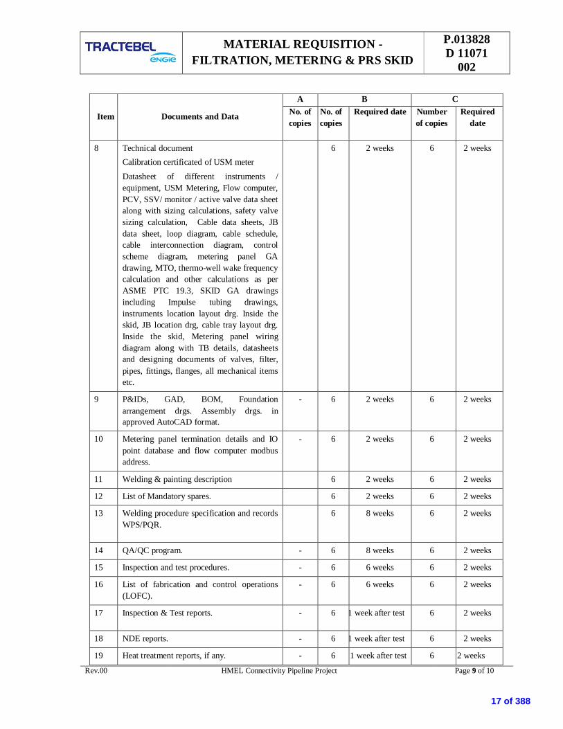
8 Technical documentCalibration certificated of USM meter
Datasheet of different instruments /equipment, USM Metering, Flow computer,PCV, SSV/ monitor / active valve data sheetalong with sizing calculations, safety valvesizing calculation, Cable data sheets, JBdata sheet, loop diagram, cable schedule,cable interconnection diagram, controlscheme diagram, metering panel GAdrawing, MTO, thermo-well wake frequencycalculation and other calculations as perASME PTC 19.3, SKID GA drawingsincluding Impulse tubing drawings,instruments location layout drg. Inside theskid, JB location drg, cable tray layout drg.Inside the skid, Metering panel wiringdiagram along with TB details, datasheetsand designing documents of valves, filter,pipes, fittings, flanges, all mechanical itemsetc.
6 2 weeks 6 2 weeks
9 P&IDs, GAD, BOM, Foundationarrangement drgs. Assembly drgs. inapproved AutoCAD format.
- 6 2 weeks 6 2 weeks
10 Metering panel termination details and IOpoint database and flow computer modbusaddress.
- 6 2 weeks 6 2 weeks
11 Welding & painting description 6 2 weeks 6 2 weeks
12 List of Mandatory spares. 6 2 weeks 6 2 weeks
13 Welding procedure specification and recordsWPS/PQR.
6 8 weeks 6 2 weeks
14 QA/QC program. - 6 8 weeks 6 2 weeks
15 Inspection and test procedures. - 6 6 weeks 6 2 weeks
16 List of fabrication and control operations(LOFC).
- 6 6 weeks 6 2 weeks
17 Inspection & Test reports. - 6 1 week after test 6 2 weeks
18 NDE reports. - 6 1 week after test 6 2 weeks
19 Heat treatment reports, if any. - 6 1 week after test 6 2 weeks
17 of 388

MATERIAL REQUISITION -FILTRATION, METERING & PRS SKID
P.013828D 11071
002
Rev.00 HMEL Connectivity Pipeline Project Page 10 of 10
Item Documents and Data
A B CNo. ofcopies
No. ofcopies
Required date Numberof copies
Requireddate
20 Hydro test and air test report. - 6 1week after test 6 2 weeks
21 QAP of all Mechanical & Instrumentationitem.
- 6 2 weeks 6 2 weeks
22 Transportation procedure to site & erectionprocedure of equipment at site.
- 6 2 weeks 6 2 weeks
23 Maintenance and operating manuals. - 6 4 weeks beforeshipping
6 2 weeks
24 Packing/shipping list with weights anddimensions.
- 6 4 weeks beforeshipping
6 2 weeks
25 List of subcontractors with their scope. - 6 2 weeks 6 2 weeks +with finaltech. file
26 FAT & SAT procedure - 6 7 weeks 6 2 weeks
27 Final technical file - 6 2 weeks 6 2 weeks
NOTES
1. Durations in column B (Required date) are weeks after Purchase Order date.
2. Durations in column C (Required date) are weeks before final dispatch.
3. Final technical document file shall be supplied in hard copy as indicated and in electronic format (.pdf Acrobatfiles) on six (6 Nos.) CD-ROMs. These documents shall be submitted along with dispatch of the system to site.
4. An offer without any of the documents mentioned in material requisition during submission of bid shall be liablefor Rejection.
5. In case of “E- bidding” bidder shall submit only one copy during bid for column A
6. Approval of tentative skid sizes before start of detailed engineering shall be taken from Owner / Owner’sRepresentative.
18 of 388
LIST OF MANDATORY SPARES –
FILTRATION, METERING & PRS SKID
P.013828
D 11075
002
Rev.00 HMEL Connectivity Pipeline Project Page 1 of 4
00 16.04.19 Issue for RFP KJ SHD SKH
Rev. Date Subject of revision Author Checked Approved
HMEL CONNECTIVITY PIPELINE PROJECT, BHATINDA
TRACTEBEL ENGINEERING PVT. LTD.
LIST OF MANDATORY SPARES
19 of 388

LIST OF MANDATORY SPARES –
FILTRATION, METERING & PRS SKID
P.013828
D 11075
002
Rev.00 HMEL Connectivity Pipeline Project Page 2 of 4
Contractor to supply 10% or minimum 1 no. (Whichever is higher) of each of the following items (whichever is
applicable) as Mandatory Spares for this project:
1. MANDATORY SPARES FOR FITRATION SKID
Sr. No. Item Description
1. Pressure Gauge
2. Pressure Transmitter
3. Differential Pressure transmitter
5. Filter:
a) Cartridge
b) QOC Gaskets & O rings of all sizes
c) Bleed through Gaskets
6. Ball Valve
2” size ( flanged end type)
7. Globe Valves
2” size (flange type)
8. Manifolds
a) 2 valve manifold
b) 5 valves manifolds
9. Instrument SS fittings, connectors, SS tube, SS valves
10. PSV
Note: Vender may include the items and its price which is not specified above.
2. MANDATORY SPARES FOR PRESSURE REDUCTION SKID.
Sr. No. Item Description Qty.
1. Pressure Gauge
2. Pressure Transmitter
3. TE along with temperature transmitter & thermowell
20 of 388
LIST OF MANDATORY SPARES –
FILTRATION, METERING & PRS SKID
P.013828
D 11075
002
Rev.00 HMEL Connectivity Pipeline Project Page 3 of 4
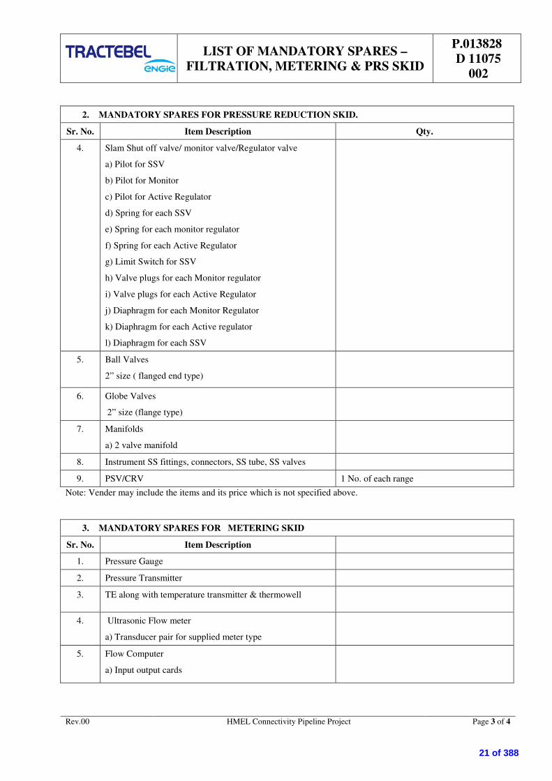
2. MANDATORY SPARES FOR PRESSURE REDUCTION SKID.
Sr. No. Item Description Qty.
4. Slam Shut off valve/ monitor valve/Regulator valve
a) Pilot for SSV
b) Pilot for Monitor
c) Pilot for Active Regulator
d) Spring for each SSV
e) Spring for each monitor regulator
f) Spring for each Active Regulator
g) Limit Switch for SSV
h) Valve plugs for each Monitor regulator
i) Valve plugs for each Active Regulator
j) Diaphragm for each Monitor Regulator
k) Diaphragm for each Active regulator
l) Diaphragm for each SSV
5. Ball Valves
2” size ( flanged end type)
6. Globe Valves
2” size (flange type)
7. Manifolds
a) 2 valve manifold
8. Instrument SS fittings, connectors, SS tube, SS valves
9. PSV/CRV 1 No. of each range
Note: Vender may include the items and its price which is not specified above.
3. MANDATORY SPARES FOR METERING SKID
Sr. No. Item Description
1. Pressure Gauge
2. Pressure Transmitter
3. TE along with temperature transmitter & thermowell
4. Ultrasonic Flow meter
a) Transducer pair for supplied meter type
5. Flow Computer
a) Input output cards
21 of 388

LIST OF MANDATORY SPARES –
FILTRATION, METERING & PRS SKID
P.013828
D 11075
002
Rev.00 HMEL Connectivity Pipeline Project Page 4 of 4
3. MANDATORY SPARES FOR METERING SKID
Sr. No. Item Description
6. Ball Valves
2” size (flanged end type)
7. Globe Valves
2” size (flange type)
8. Manifolds
a) 2 valve manifolds
9. Instrument SS fittings, connectors, SS tube, SS valves
10 Panel Accessories
a) Indication Lamps
b) Push buttons
c) Barriers of each type
d) Repeaters of each type
e) Dual channel Digital bar graph indicator
f) MCB of each type
g) Relays / Relay Module
Minimum 10% or 1(whichever is higher) for
each type.
Note: Vender may include the items and its price which is not specified above.
22 of 388

P.013828 D 11040
002
Sr. No. NAME OF VENDOR ADDRESS DELHI / NCR ADDRESS Telephone & Fax.No. Email-Id
1 Maharashtra Seamless Ltd. 106, Nilgiri Appt., 9, Barakhamba Road,New Delhi 110 001
Tel: 91-11-23718367, 23710862,23213631Fax:
E-mail: [email protected]
2 Indian Seamless Metal Tubes Eden Park, C-Wing, Off Pune - Nagar Road, Viman Nagar,Pune - 411 014
Tel: 020-2650 4038 / 26630715Fax: E-mail: [email protected]
3 DYLAN Belgium Lerenveld 20 2547 Unity, Belgium Tel: 32 3 488 48 80Fax: 32 3 488 48 80 E-mail: [email protected]
4 F.B.F. Belgium Dynamicalaan 4-8, 2610 Antwerpen, Belgium. Tel: 32 3 820 58 80Fax: 32 3 828 96 22 E-mail: [email protected]
5 Ferrostaal (MAN Group), Germany Hohenzollernstrasse 24, 45128 Essen, Germany
MAN Ferrostaal AG Liaison Office401, Bhikaiji Cama Bhawan,11 Bhikaiji Cama Place New Delhi 110 066Phone +91 11 26185304, 26173143, 26185882Fax +91 11 26192731
Tel : 49 201 81801Fax : 49 201 8182822
E-mail: [email protected]
6 INTERFORGE Grobe Strabe 14, D-27356 Rotenburg, Germany Tel: 49 4261 6709-0 / 42614081Fax: 49 4261 3090 E-mail: [email protected]
7 KURVERS Piping, Neitherlands Mark S. Clarkelaan 13 a Haven No. M 512 4761 RK Zevenbergen \THE NETHERLANDS
Tel: 31 168 334344Fax: 31 168 334349 E-mail: [email protected]
8 MEREK Engineering Premier estate Leys Road Brockmoor Brierley Hill, DY5 3UT WestMidlands, UNITED KINGDOM
Tel: 44 121 544 9938Fax: 44 121 544 9132 E-mail: [email protected]
9 TelOCEENNE, Belgium Ten Bergstraat 4 2830 WIllebroek BELGIUM Tel: 32 3 860 73 70Fax: 32 3 860 7371 E-mail:
10 VAN LEEUWEN BUIZEN Schaarbeeklei 189 1800 Vilvoorde BELGIUM Tel: 32 2 255 40 00Fax: 32 2 253 20 92 E-mail:
NO.2, Gul Circle, Jurong Industrial Estate,Singapore-629560
Tel: 0065-865 288,70065 9783 7381
A-1/14-3, Millenium Tower, Sector 9, Sanpada,Navi Mumbai 400705 Tel : +91 99675 96081 E-mail : [email protected]
Level 33, menara Maxis,Kuala Lumpur City Centre,50088 Kuala Lumpur, Malaysia
Tel : 6(03) 23000762fax : 6(03) 2300 0760 E-mail :[email protected]
2 MSA Hlucinska, 41747 22Dolni Benesov CZECH REPUBLIC
Tel :+ 420 553 881 111Fax : 420 553 651 236 Email: [email protected]
3 PETRO VALVES 11248 East Hardy St. Houston, Tx 77093 713-676-1212 800-255-9527 fax 713-467-3876 Tel : 39-331334111Fax : 39-331675, 830
VENDOR LIST
MECHANICAL
1
STATION PIPE
BALL VALVES
COOPER CAMERON VALVES
1 of 31
23 of 388

P.013828 D 11040
002
Sr. No. NAME OF VENDOR ADDRESS DELHI / NCR ADDRESS Telephone & Fax.No. Email-Id
VENDOR LIST
4RMA Maschinen- und
Armaturenbau Faulhaber &Truttenbach
RMA Maschinen & Apparatebau Faulhaber & Truttenbach KGOSTSTR. 17, 77694 KEHL / GERMANY
Tel : +49 (0) 7851 - 868 - 0Fax : +49 (0) 7851 - 868 - 13
5 SCHUCK ARMATUREN (exBORSIG)
FRANZ SCHUCK GMBHDAIMLERSTRABE 4-789555 STEINHEIM, GERMANY
418, QUTAB PLAZA,DLF CITY PHASE - 1, GURGOAN - 122002Tel : +91-124- 423 58 00
Tel : +49 7329 950 - 0 E-mail : [email protected] : [email protected]
6 TORMENE GAS TECHNOLOGY- (VALVITALIA) Via Campolongo, 97 35020 Due Carrare PD, Italy Ph: +39.049.9199611
Fax: +39.049.9125455 E-mail [email protected]
7 Breda Energia Spa Viale Sarca 336, 20126 Milano, Italy Tel: 39 02 64477512, 02- 644771Fax : 39 02 64477544 E-mail : [email protected]
8 TRP (Perar), srl, Italy Via Grigna,37 20027 Rescaldina (MI) - Italy Tel: 39 0331 465208Fax : 39 0331 465731 E-mail : [email protected]
9 Grove dresser Italia, Italy 23018 TALAMONA (SO) VIA ROMA 32, ITALY
10 Microfinish Valves
Microfinish Group of CompaniesB 161-162, Industrial Estate, Gokul Road,Hubli - 580 030,Karnataka, India
Tel : 0120-3259966, 2510145Fax : 0120-2510157 Tel : 0836 - 2212404, 2210611 Email : [email protected]
Email : [email protected]
11 Virgo Valves
Virgo Engineers LimitedVirgo Valves and Controls Limited277, Hinjewadi Telase - II, Maan (Mulshi),Pune - 411 057, India
Tel : 020 - 66744000 Email : [email protected] : [email protected]
12 L & T Limited (Audco India Ltd.)Larsen & Toubro LimitedValves Business Group10 Club House Road, Anna Salai, Chennai - 600 002, India
32, Shivaji Marg, Moti Nagar, New Dekhi - 110015Tel : 011 - 41419500-02Fax : 011 - 41419600, 41419596
Tel : 044 - 2846 2082 / 22492323Fax: 044 - 22495055 Email : [email protected]
13 Flow Chem
Flowchem Industries10, Navdurga Industries Estate,Opp. Forge & Blower Co., Naroda Road,Ahmedabad - 380 025, Gujarat - India
Tel : 079 - 2220 4773
1 M/s BIFI Italy
2 M/s Rotork fluid Sytem Italy
3 PC Intertecnik Germany
4 M/s Bettis Belgium
5 Schuck
6 Rotex
GAS OVER OIL ACTUATORS
2 of 31
24 of 388

P.013828 D 11040
002
Sr. No. NAME OF VENDOR ADDRESS DELHI / NCR ADDRESS Telephone & Fax.No. Email-Id
VENDOR LIST
1 NECO ValvesNSSL LimitedF-8, M.I.D.C Industrial Area, Hingna Road,NAGPUR - 440 016 INDIA
Neco Schubert and Salzer Ltd.,D- 307, Defence Colony, New Delhi - 110024Tel : 011 - 24642190, 24641579Fax : 011 - 24642190
Tel : 07104 -237276, 237471Fax : 07104 -236255, 237583
E-mail - [email protected] - [email protected]
2 Oswal IndustriesOswal Valves Pvt. Ltd1-A, Patel Industrial Estate, Navpada Road,Oshiwara, Jogeshwari (W), Mumbai - 400102
Tel : 022 - 6771733, 30088001 - 5Fax : 022 - 23861642 Email : [email protected]
3 L & T Limited (Audco India Ltd.)Larsen & Toubro LimitedValves Business Group10 Club House Road, Anna Salai, Chennai - 600 002, India
32, Shivaji Marg, Moti Nagar, New Dekhi - 110015Tel : 011 - 41419500-02Fax : 011 - 41419600, 41419596
Tel : 044 - 2846 2082 / 22492323Fax: 044 - 22495055 Email : [email protected]
4 Panchvati Valves & Flanges Pvt.Ltd.
Panchwati Valves & Flanges Pvt. Ltd.Shop No. 5, Ground Floor, Sejal- Kajal Apartments,Ram Mandir Road, Goregaon (W), Mumbai - 400104
Tel : 022 - 26762957
5 Leader Valves Ltd. LEADER VALVES LTD.S-3, S-4, Industrial Town, Jalandhar - 144 004 Tel : 0181 - 2490666, 777, 888, 999
6 Galperti Engineering & Flowcontrol spa Zona Industriale-23823 Colico (LC), Italy Fax : 0039 0341-930780 Email: [email protected]
7 Douglas Chero SPA Loc Pradaglie, 29013 Carpento, Piacentino, Italy Tel : 0039 0523 854011Fax :0039 0523 85 03 89 Email: [email protected]
8 Niton Valves Industries Ltd. D-115/116 Ghatkopar Industrial Estate, L.B.S. Marg, Ghatkopar(West),Mumbai-400086
Tel : 022-5008315Fax : 022-5007654/5007436 Email : [email protected]
9 Shalimar Plot NO. R-846/1, MIDC, TTC Industrial Area, RabaleDist.-Thane, Navi Mumbai - 400 701
Tel : 91-22-27642546/47/48Fax : 91-22-27605551/3 E-mail : [email protected]
1 Econo Valves Pvt. Ltd. 197 SIDCO Industrial Area AmbatturCHENNAI - 600 098
Tel : +91 44 6251829 / 6254371Fax :+91 44 6257501
2 L&T Audco Valves Chennai
3 Steel Strong Valves (P) Ltd. Plot no. R-241, TTC Industrial Area MIDC,Rabale, New Bombay-400701
Tel : +91 22 27699489/90Fax: +91 22 27695537
4 Oswal Industries Ltd
Oswal Industries Limited404, Sakar-IIIOpp. Old High CourtAhmedabad – 390 014
Tel : +91 79 30947636Fax: +91 79 27540839
5 B.D.K Engineering Ltd., HubliB.D.K. Engineering (I) Ltd.Gokul roadHubli 580 030
Tel : +91 836 331499/ 333930
GLOBE VALVES
CHECK VALVES
3 of 31
25 of 388

P.013828 D 11040
002
Sr. No. NAME OF VENDOR ADDRESS DELHI / NCR ADDRESS Telephone & Fax.No. Email-Id
VENDOR LIST
6 Flow Chem Industries
Flow Chem Industries10, Navdurga Indl. EstateOpp. Forge BlowerNaroda RoadAhmedabad – 25
Tel : +91 79 220 4773/3623
7 NECO Schubert & Salzer Ltd. Nagpur
8 Leader Valves Ltd. S-3&4, Industrial Town, Jallandhar 144 004 Tel : +91 181 2290341/2290342Fax: +91 181 2290894
9 Niton Valve Industries Pvt. Ltd.D-115/116 Ghatkopar Industrial Estate L.B.S.Marg Ghatkopar (West)MUMBAI - 400 086
Tel : +91 22 5008315Fax: +91 22 5007654 / 5007436
1 FMC Sanmar Ltd. 147, Karapakkam Village, CHENNAI - 600 096 Tel : +91 44 4925455
2 Protego Equipments Pvt. Ltd. , Navi Mumbai
3 Larsen & Toubro 32, Sivaji Marg, Post Box No.6223, Near Moti Nagar, NEW DELHI Tel :+91 11 5931302Fax:+91 11 5438624
4 Mekaster (Formerly SEBIM)Valves India Pvt. Ltd. 908, Ansal Bhawan, 16, Kasturba Ghandhi Marg, New Delhi-110 001 Tel : +91 11 3312110/ 3318360
Fax: +91 11 3712155
5 RMG Regal + Messtech GmbH,Germany Germany Tel : 0181 - 2490666, 777, 888, 999
1 GENOYER Group Genoyer9/11, rue de Losbonne, 13742 Vitrolles
Tel :+32 3 860 73 70Fax : 322 253 20 92
2 TECHNOGORGE- Italy(International Piping Group)
International Piping Group, Inc.2523 Fairway Drive, Suite 500Houston, Texas 7003
E-mail : [email protected]
3 Siddharth & Gautam- FaridabadSiddharth MakkerPiyala Road, SikriBallabhgarh, Faribabad
Tel : +129 - 2205120 -121Fax : +129 - 2205135 E-mail:[email protected]
4 FBF Global Services Co. 5000 Watkins Way, Suite 124,Friendswood, TX 77546
Tel: 832.434.3236Fax: 281.648.2272
Email:- [email protected],[email protected]
5 Allied International SRL Italy loc. Vascellino 29010 Nibbiano (PC) - ITALY Tel : +39 0523 991 211Fax : +39 0523 993 036
6 Bassi Luigi Fittings B.V. HollandBassi Luigi & C spaStabilimento e Uffici : Via Buttirone, 126865 S Rocco al Porto (LO), ITALY
Tel: ++39 377 56023Fax : ++39 377 569371
7 GAM Raccordi Spa ItalyGAM Raccordi S.P.AVia Roma, 29, GAZZOLA (Placenza)ITALY 29010
Tel: +39 0523 975500Fax: +39 0523 975544 E-mail : [email protected]
PRESSURE RELIEF/SAFETY VALVE (PRV/PSV)
PIPE FITTINGS
4 of 31
26 of 388

P.013828 D 11040
002
Sr. No. NAME OF VENDOR ADDRESS DELHI / NCR ADDRESS Telephone & Fax.No. Email-Id
VENDOR LIST
8 TelOCEENNE (Groupe Genoyer)Teloceene Asia Pte Ltd.171 Chin Seww Road, #11 - 09 San CentreSingapore
9 Teekay Tube 315/317, Navratna 69, P D Mello Road, Near Camac bridge, Mumbai-400009
Tel: +91 22 23423382/83,23437716/23445477
10 Pipefit Engineers 496/1, GIDC Industrial estate, Majarpura, Baroda-390010 Tel: +91 265 2645177Fax: +91 265 2645477 Up to 12"
11 Sawan Engineers Baroda
1 Echjay Industries Pvt. Ltd. AJI Industrial Estate, Lalpari Lake road, Rajkot-360003, Gujarat Tel :+91 281 2387482-86/3018300Fax : +91 281 2387847 [email protected]
2 CD Industries Plot No. 3, South of GT road, BS road Industrial area, Ghaziabad Tel :+91 120 2866744/2866742Fax : +91 120 2866743/2866369
[email protected]@cdind.org
3 Choudhary Hammer Works PO Box No. 20, Near Hapur road Opposite Power House, Ghaziabad Tel :+91 120 4388000/4376972-74Fax : +91 120 4376970/71 [email protected]
4 Metal Forgins (P) Ltd. B-1, Mayapuri Industrial area, Ph. -1, New Delhi Tel :+91 11 28114376/28114458Fax:+91 11 28115759/41833103 [email protected]
5 Punjab Steel Works B 38, Mayapuri Industrial Area, Ph.-1, New Delhi Tel :+91 11 28115960Fax:+91 11 28117432 [email protected]
6 JAV Forgings Pvt. Ltd. Plot No. 5, Sector-6, Mathura road, Faridabad-121006, Haryana, Tel: +91 129 2480275/2480046Fax:+91 129 2481750
7 C D Engineering Co. C-199, Bulendshahar Road Industrial Area, Ghaziabad Tel: +91 120 2866315/316/317Fax: +91 120 2866319 [email protected]
8 J K Forgings B - 83, Mayapuri Industrial area, Ph. - 1, New Delhi-110064Tel: +91 1125141825/28115213/28114484Fax: +91 11 25133161
1 Multi Thread Fasteners ,BarodaMulti Thread Fasteners.,885/B GIDC Makarpura,Baroda – 390010
Tel :+91 265 2647310Fax:+91 265 2642821
2 Precision Engineers Baroda
1 Covalence Raychem (BERRYPlastics Corporation) 709/710, Tolstoy House, Tolstoy Marg, New Delhi - 110 001
FASTENERS
FLANGES
HEAT SHRINKABLE SLEEVES
5 of 31
27 of 388

P.013828 D 11040
002
Sr. No. NAME OF VENDOR ADDRESS DELHI / NCR ADDRESS Telephone & Fax.No. Email-Id
VENDOR LIST
2 Canussa (Bhotika Brothers- IndianRepresntative)
Bhotika Brothers, 59, R.N.Arcade,1st Floor, Lokhandwala Complex,Andheri West ,Mumbai-400053
Tel :+91 22 6331458/9Fax:+91 22 6362253
1 Denso GmbH P.O.Box 15 01 20 * D-51344 Leverkusen, Germany Tel :+49 214 2602-0Fax:+49 214 2602-318
2 Polyken (BERRY PlasticsCorporation) 709/710, Tolstoy House, Tolstoy Marg, New Delhi - 110 001
1 Denso GmbH P.O.Box 15 01 20 * D-51344 Leverkusen, Germany Tel :+49 214 2602-0Fax:+49 214 2602-318
2 Powercrete (BERRY PlasticsCorporation) 709/710, Tolstoy House, Tolstoy Marg, New Delhi - 110 001
1 Welspun Gujarat Stahl Rohren Ltd Trade World, B-wing, 9th Floor, Kamala Mills Compound, SenapatiBapat Marg, Lower Parel, Mumbai - 400 013, India.
36, Bawa Potteries Complex,Aruna Asaf Ali Marg, Vasant Kunj, New Delhi - 110 070, India.Tel : +91 11 2602 2051 / 2612 2054Fax : +91 11 2612 2064
Tel : 022-66136000Fax : 022-24908020,Fax : 022-24908021
[email protected][email protected][email protected]
2 Jindal Saw Ltd.Jindal Center12. Bikhaji Cama placeNew Delhi-110066
Tel : 011-26188360Fax : 011-26170691
Email : [email protected] : [email protected]
3 PSL Holdings Ltd PSL Towers, Plot no. 615, Makwana Road, Marol, Andheri(E), Mumbai-400025, Maharastra
B-96, Greater Kailash - 1, New Delhi - 1100 48Tel : 011 - 292447124 , 29238290Fax: 011 - 29235745, 2923 6753
Tel : 022-56447777 / 88Fax : 022-56447700
[email protected]@[email protected]
1 Raci Italy
2 Raychem RPG Limited 709/710, Tolstoy House, Tolstoy Marg, New Delhi - 110 001
1 Raci Italy
1 PLN Construction Pvt. Ltd. (India)
2 Cherington Asia (India) Pvt. Ltd.
3 Essar Construction Ltd. Essar House, PO 7945, Mahalaxi, Mumbai -400 034
COLD APPLIED TAPES
HDD CONTRACTORS
PUR COATING
SPACER / INSULATOR
CASING END CLOSURE
LR & INDUCTION BENDS
6 of 31
28 of 388

P.013828 D 11040
002
Sr. No. NAME OF VENDOR ADDRESS DELHI / NCR ADDRESS Telephone & Fax.No. Email-Id
VENDOR LIST
4Mersing Construction and
Engineering Sdn Bhd., Selangor(Malaysia)
5 Herrenknecht (Asia) Ltd.(Thailand)
6 Horizontal Drilling International(France)
7 COE Drilling Australia PTY Ltd.(Australia)
1 Rosen Euro BV, Netherlands
2 M/s PII, U.K
3 NGKS, Russia
4 TDW Williams
5 VEE KAY Vikram Ahmedabad
1 Parry EID, Parry (India) Ltd. Chennai
2 Hindustan Hindustan Sanitaryware and Industries, Bahadurgarh
3 Cera Madhusudan Ceramics, Ahmedabad
1 AMC Ashok Mfg. Co., New Delhi
2 Neelkanth Neelkanth Mfg. Co. , New Delhi
1 Parco Prakash Brassware Ind., New Delhi
CIVIL
VITREOUS CHINA SANITARYWARE
STAINLESS STEEL SINKS
C.P FITTINGS
INTELLIGENT PIGGING CONTRACTOR
7 of 31
29 of 388

P.013828 D 11040
002
Sr. No. NAME OF VENDOR ADDRESS DELHI / NCR ADDRESS Telephone & Fax.No. Email-Id
VENDOR LIST
2 GEM Germ Sanitary Appliances Pvt. Ltd.
1 ESS ESS Bathroom Products Pvt. Ltd., Panchkula, Haryana
2 Lotus DP Gupta & Co. New Delhi
3 Orient Venus Metal Ind. New Delhi
1 Supreme Supreme Industries, Mumbai
2 Prince Selfshine Industries Mumbai
1 Ultra filter
2 Chemtrols
3 Emerson
4 Flash Point
5 Grand Prix Fab (Pvt.) Ltd
6 Multitex Filteration Engg. (P) Ltd.
7 Forain SRL (Italy)
8 Perry Equipments Corp. (USA)
9 SYRTEC International ContractorSPA (Itealy)
10 Faudi Filter Systems GMBH(Germany)
11 Axsia Howmar Ltd (UK)
12 Plenty Filter (UK)
13 Vanaz
C.P ACCESSORIES, WASTE FITTINGS
PVC PIPES
FILTERS
8 of 31
30 of 388

P.013828 D 11040
002
Sr. No. NAME OF VENDOR ADDRESS DELHI / NCR ADDRESS Telephone & Fax.No. Email-Id
VENDOR LIST
14 Control Plus
15 Nirmal Industrial Controls Pvt. Ltd.
1 TATA TISCO-Tubes, Jamshedpur
1 KITEC Kitec Industries, Baroda
1 Leader Leader Engineering Works, Jalandhar
2 Zolote Zolote Industries, Jalandhar
1 Kirloskar Kirloskar Bros Ltd., Pune
1 Perfect Perfect Potteries, Jabalpur
1 Hasti NOCIL, Bangalore
2 Oriplast Oriplast Ltd., Balasore, Orissa
1 Sintex
COMPOSITE PIPES & FITTINGS
GI PIPES/MS PIPES
GUN METAL VALVES AND LOCKS
CI DOUBLE FLANGED SLUICE VALVES, NON RETURN VALVES
STONE WARE PIPE AND GULLY TRAPS
HDPE PIPES AND FITTINGS
WATER TANKS
ALUMINIUM HARDWARE
9 of 31
31 of 388

P.013828 D 11040
002
Sr. No. NAME OF VENDOR ADDRESS DELHI / NCR ADDRESS Telephone & Fax.No. Email-Id
VENDOR LIST
1 Earibihari
1 Modiguard
2 Atul
1 Hindalco
1 L&T
2 Birla
1 Asian
2 Beger
3 Nerolac
4 Shalimar
5 Bombay
1 Kajaria
2 Johnson
GLASS
ALUMINIUM DOOR/WINDOW SECTION
CEMENT
PAINTS
CERAMIC/VITRIFILED/VITREOUS TILES
10 of 31
32 of 388

P.013828 D 11040
002
Sr. No. NAME OF VENDOR ADDRESS DELHI / NCR ADDRESS Telephone & Fax.No. Email-Id
VENDOR LIST
3 Somany
1 SAIL
1 TISCO Jamshedpur
SAIL
1 Sudhir Engg. Co. 507, International Trade Tower, Nehru Place, NEW DELHI - 110 019 Tel: +91 11 646 6293
2 Powerica Limited 1214, Hemkunt Tower, Nehru Place, NEW DELHI - 110 019 Tel: + 91 11 646 2451
3 Bhaskar Power Project Ltd. B-137, Sector - 2, NOIDA - 201 301 UTTAR PRADESH Tel: +91 118 4521355
4 Jakson Engineers Ltd. A-43, Phase II (Extension), NOIDA - 201 305 UTTAR PRADESH Tel: +91 118 4563156
1 Diesel Engine Cummins / Kirloskar
2 Geneerator KEC / Jyoti / NGEF / Stamford / CGL
1 Sudhir Engg. Co. 507, International Trade Tower, Nehru Place, NEW DELHI - 110 019 Tel: +91 11 646 6293
2 Powerica Limited 1214, Hemkunt Tower, Nehru Place, NEW DELHI - 110 019 Tel: + 91 11 646 2451
SILENT D.G. SET SUPPLIER
REINFORCEMENT STEEL
AMF DG SET
ELECTRICAL
SILENT D.G. SET
STRUCTURAL STEEL
11 of 31
33 of 388

P.013828 D 11040
002
Sr. No. NAME OF VENDOR ADDRESS DELHI / NCR ADDRESS Telephone & Fax.No. Email-Id
VENDOR LIST
3 Jakson Engineers Ltd. A-43, Phase II (Extension), NOIDA - 201 305 UTTAR PRADESH Tel: +91 118 4563156
1 Contronics Switchgear (I) Pvt. Ltd. A-30, Sector-58, NOIDA - 201301, UTTAR PRADESH Tel: +91 118 4583472
2 Elpro Engineering Plot No.4458, Y-95, 8th Street, Anna Nagar, CHENNAI-600040 Tel: +91 44 6281214
3 RYB Switchgears Pvt. Ltd. C-543, 2nd Floor, Saraswati Vihar, DELHI - 110034 Tel: +91 11 27012329 / 07010097
4 Trident Switchgears Mata Bhavan, C-49, Jangpura Extension, NEW DELHI - 110014 Tel: + 91 11 24313946
5 Birla Ericsson Optical Ltd. Udyog Vihar, P.O. Chorthala, Rewa, MADHYA PRADESH-486006 Tel: +91 7662 280580Fax: +91 7662 280680
6 MileStones Switchgear Pvt. Ltd. D-92/8, Okhla Industrial Area, Phase-I, NEW DELHI - 110020 Tel: +91 11 26815500 / 26815501
7 Vidhyut Control (I) Pvt. Ltd. D-12, Sector-17, Kavi Nagar Industrial Area, GHAZIABAD-201301,UTTAR PRADESH Tel: +91 575 4701223 / 4700112
8 Electronic Insatrumentation &Control
Plot No.436, Phase-II, G.I.D.C. Estate, Vatva, AHMEDABAD-382445,GUJARAT Tel: +91 5830505, 5831665
9 Crompton Greaves Ltd.
10 Larsen & Toubro Ltd.
11 Control & Switchgear Co. Ltd. 222, Okhla Industrial Estate, NEW DELHI - 110020 Tel: +91 11 26847154 / 26829063
1 Universal Cables Ltd., M.P.
2 Fort Gloster Industries Ltd.
3 Associated Flexibles & Wires Pvt.Ltd., Mumbai
4 NICCO Corporation Ltd., Baroda
MAIN / SECONDARY, MEDB, DCDB & UPS DISTRIBUTION BOARD
POWER CABLES
12 of 31
34 of 388

P.013828 D 11040
002
Sr. No. NAME OF VENDOR ADDRESS DELHI / NCR ADDRESS Telephone & Fax.No. Email-Id
VENDOR LIST
5 Cable Corporation of India Ltd.
6 KEI Industrie Ltd.
7 Grandlay
8 Ravin Cables Ltd.
9 Thermopads Pvt. Ltd.
10 R.P.G. Cable Ltd.
11 Finolex Cable
12 Delton Cables Ltd.
13 Polycab Wire Pvt. Ltd.
14 CORDS Cable Industries
15 Finolex Cable
16 GESCAB Industries Ltd.
17 INCAB
1 Balinga Lighting Equipments Pvt.Ltd.
2 Sudhir Switch Gears Pvt. Ltd.
3 Flame Proof Control Gears Pvt.Ltd.
4 Flame Proof Equipment Pvt. Ltd.
FLAMEPROOF LIGHTING FIXTURES, FLP, J.BOX/FLP SWITCH SOCKET
13 of 31
35 of 388

P.013828 D 11040
002
Sr. No. NAME OF VENDOR ADDRESS DELHI / NCR ADDRESS Telephone & Fax.No. Email-Id
VENDOR LIST
5 Flex Pro Electricals Pvt. Ltd.,Navsari
6 CEAG
1 B.C.H.
2 Baliga Lighting Equipments Pvt.Ltd.
3 CGL
4 MDS
1 Crompton Greaves Ltd.
2 Philips
3 Bajaj Electrical Ltd.
4 KESELEC Schreder
1 Fuji Electric Company Limited
2 Hi-REL Controls Ltd. B-14/1, G.I.D.C. Electronics Zone, Sector-25, GANDHINAGAR -382044, GUJARAT Tel: +91 7932 21636 / 22531
3Emmerson Network Power
Management (Formerly known asTata Libert)
4 Gutor Electronics Ltd. (L&T Representative)
5 Kerala State ElectronicsDevelopment Corporation Ltd.
Keltron Equipment Complex, Karakulam, Thiruvananthapuram -695564
SWITCH SOCKET AND PLUGS
LIGHTING FIXTURES
U.P.S
14 of 31
36 of 388
P.013828 D 11040
002
Sr. No. NAME OF VENDOR ADDRESS DELHI / NCR ADDRESS Telephone & Fax.No. Email-Id
VENDOR LIST
6 Gutor Electronics Ltd.(L&T Representative)
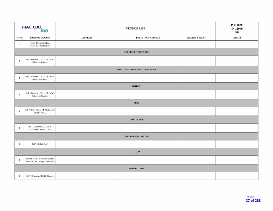
1 L&T / Siemens / CGL / GE / CSC /Schneider Electric
1 L&T / Siemens / CGL / GE / SCS /Schneider Electric
1 L&T / Siemens / CGL / GE / CSC /Schneider Electric
1 L&T / EE / CGL / GE / SchneiderElectric / CSC
1 L&T / Siemens / CGL / GE /Schneider Electric / CSC
1 IMP / Rishab / AE
1 Indcoil / Gm / Koppa / Silkana /Siemens / AE / Pragati Electricals
1 L&T / Siemens / BCH / Kaycee
INSTRUMENT / METER
AIR CIRCUIT BREAKER
MOULDED CASE CIRCUIT BREAKER
SWITCH
FUSE
CONTACTOR
CT / PT
PUSH BUTTON
15 of 31
37 of 388
P.013828 D 11040
002
Sr. No. NAME OF VENDOR ADDRESS DELHI / NCR ADDRESS Telephone & Fax.No. Email-Id
VENDOR LIST
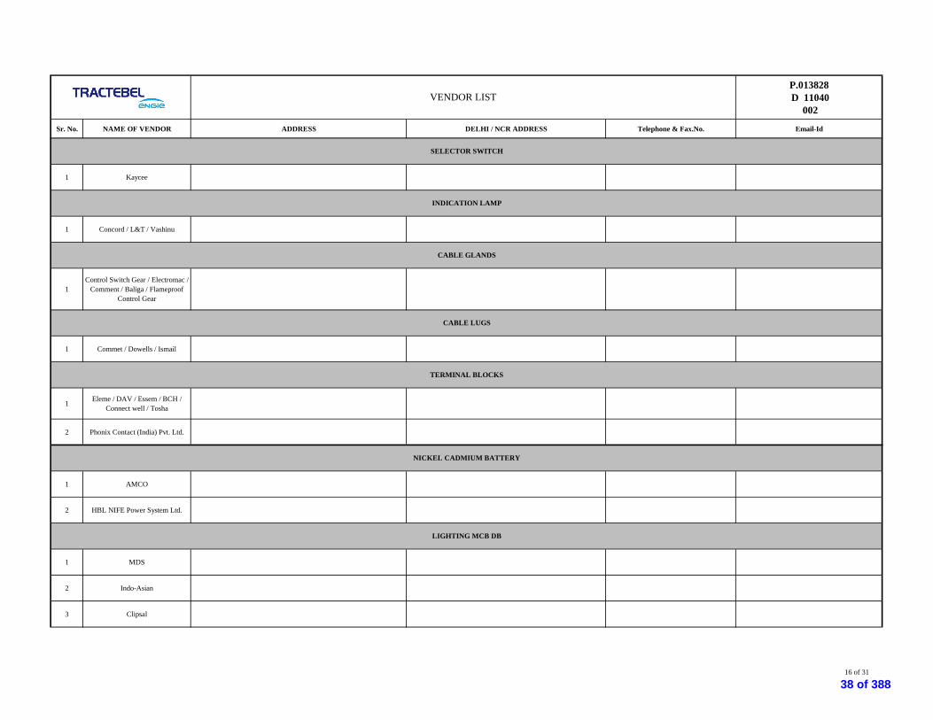
1 Kaycee
1 Concord / L&T / Vashinu
1Control Switch Gear / Electromac /
Comment / Baliga / FlameproofControl Gear
1 Commet / Dowells / Ismail
1 Eleme / DAV / Essem / BCH /Connect well / Tosha
2 Phonix Contact (India) Pvt. Ltd.
1 AMCO
2 HBL NIFE Power System Ltd.
1 MDS
2 Indo-Asian
3 Clipsal
SELECTOR SWITCH
NICKEL CADMIUM BATTERY
INDICATION LAMP
CABLE GLANDS
CABLE LUGS
TERMINAL BLOCKS
LIGHTING MCB DB
16 of 31
38 of 388
P.013828 D 11040
002
Sr. No. NAME OF VENDOR ADDRESS DELHI / NCR ADDRESS Telephone & Fax.No. Email-Id
VENDOR LIST
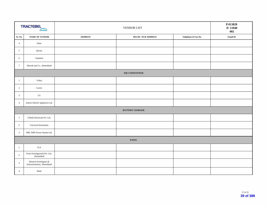
4 Datar
5 Havels
6 Standard
7 Shrenik and Co., Ahmedabad
1 Voltas
2 Carrier
3 LG
4 Amtrex Hitachi Appliances Ltd.
1 Chhabi Electricals Pvt. Ltd.
2 Universal Instruments
3 HBL NIFE Power System Ltd.
1 ICA
2 Swati Switchgears(I) Pvt. Ltd.,Ahmedabad
3 Elemech Switchgears &Instrumentations, Ahmedabad
4 Rittal
BATTERY CHARGER
AIR CONDITIONER
PANEL
17 of 31
39 of 388

P.013828 D 11040
002
Sr. No. NAME OF VENDOR ADDRESS DELHI / NCR ADDRESS Telephone & Fax.No. Email-Id
VENDOR LIST
5 Pyrotech Controls
6 Enclotek
1 MTL
2 P&F
1 Patson Transformers Pvt. Ltd.,Ahmedabad
2 Voltamp Transformers Pvt. Ltd.,Ahmedabad
1 Mitcorr Cathodic Protection Pvt.Ltd., Baroda
West Wing, 1st Floor, G.S.C.B Building, B/h Bank of India, ElloraPark, Baroda - 390007
Tel: +91 265 2397424 / 2396844Fax: +91 265 2397424
2 Corrosion Control Servcies(B) Pvt.Ltd., Mumbai 405, Arun Chambers, Tardeo Road, Mumbai - 400034 Tel: +91 22 23524593, 56627010
Fax: +91 22 24934570
3 Raychem RPG Ltd. 709/710, Tolstoy House, Tolstoy Marg, New Delhi - 110 001
4 Corrtech International Pvt. Ltd.,Ahmedabad
22, Dhara Centre, Vijay Cross Road, Navrangpura, Ahmedabad -380009
Tel: +91 79 26563443, 26568639Fax: +91 79 26431615
1 Saroj Urja Services Co A-14, navjivan Soc., Dahej bypass road Tel: +91 98244 75574
2 Solartech System B-2, Lalita Co-op Hou.Soc. Isanpur raod, Ahmedabad Tel: +91 98254 11692
3 Khodiyar Enterprise Jay marketing, Sukrut Apt., HJ Doshi Hospital Road, Rajkot Tel: +91 98251 62853
4 Hitech Industrial Corp. 206, Kalptaru Complex, Indira Circle, Rajkot Tel: +91 281 258 5532
I.S. BARRIER / REPEATER
TRANSFORMER
CATHODIC PROTECTION SUB-CONTRACTOR
SOLAR LIGHT
18 of 31
40 of 388

P.013828 D 11040
002
Sr. No. NAME OF VENDOR ADDRESS DELHI / NCR ADDRESS Telephone & Fax.No. Email-Id
VENDOR LIST
1 Emerson Process Management
2 Invensys
3 Honeywell
4 Fuji
5 Yokogawa
6 ABB
7 Endress & Hauser
1 Pyroelectric Instruments
2 General Instruments
3 A.N. Instrument
4 Altop industries
5 Baumer Bourdon
6 Thermo-Couple Product co india
7 Techno Instruments
8 Wika
INSTRUMENTATION
PRESSURE, DIFF.PRESSURE/ TEMPERATURE TRANSMITTER
TEMPERATURE ELEMENT WITH THERMOWELL
19 of 31
41 of 388

P.013828 D 11040
002
Sr. No. NAME OF VENDOR ADDRESS DELHI / NCR ADDRESS Telephone & Fax.No. Email-Id
VENDOR LIST
1 General Instruments
2 Pyroelectric Instruments
3 A.N. Instrument
4 Waree Instruments
5 Bumer Technologies india
6 Wika Instrument India Ltd
7 Altop Industries
1 Magnetrol
2 Magnetrol-USA
3 Dag Process Instruments – India
4 Chemtrols Engineering – India
5 MSW Controls – UK
6 Bliss Anand Pvt. Ltd. – India
7 Forbes Marshal
8 Tokyo Keiso - Japan
TEMPERATURE GAUGE WITH THERMOWELL
LEVEL GAUGE
LEVEL SWITCH
20 of 31
42 of 388

P.013828 D 11040
002
Sr. No. NAME OF VENDOR ADDRESS DELHI / NCR ADDRESS Telephone & Fax.No. Email-Id
VENDOR LIST
1 Chemtrols
2 V.Automate
3 Bliss Anand
4 Magnetrol – USA
5 Ametek – USA
6 Manometer – India
7 Gauge Bourdon
8 R.K Dutta India
1 Chemtrols Industries lts
2 Dresser Product Industrial India
3 Foxboro eckardt GmBh
4 Invensy India Ltd
5 Emerson Process Management
1 ABB INC
2 Endress & Hauser
3 Emerson Process Management
DISPLACER LEVEL INSTRUMENTS
RADAR LEVEL INSTRUMENTS
21 of 31
43 of 388
P.013828 D 11040
002
Sr. No. NAME OF VENDOR ADDRESS DELHI / NCR ADDRESS Telephone & Fax.No. Email-Id
VENDOR LIST
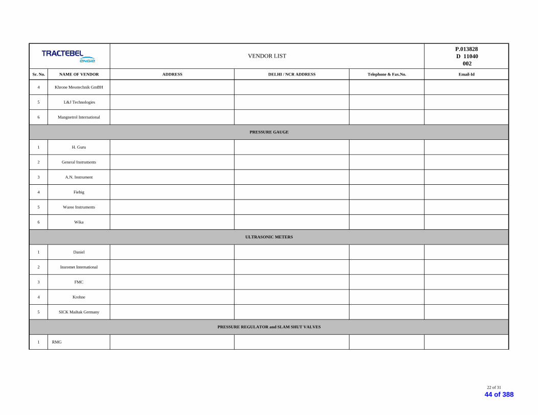
4 Khrone Messtechnik GmBH
5 L&J Technologies
6 Mangnetrol International
1 H. Guru
2 General Instruments
3 A.N. Instrument
4 Fiebig
5 Waree Instruments
6 Wika
1 Daniel
2 Insromet International
3 FMC
4 Krohne
5 SICK Maihak Germany
1 RMG
ULTRASONIC METERS
PRESSURE GAUGE
PRESSURE REGULATOR and SLAM SHUT VALVES
22 of 31
44 of 388

P.013828 D 11040
002
Sr. No. NAME OF VENDOR ADDRESS DELHI / NCR ADDRESS Telephone & Fax.No. Email-Id
VENDOR LIST
2 Pietro Fiorenteni
3 Emerson Process Management
4 Schlumberger
5 Gorter controls
6 Nirmal
7 Instromet International NV
1 ABB Ltd (Faridabad), India
2 Daniel Measurement & ControlAsia Pacific, India
3 Instromet Internationa, NV
4 Honeywell
1 Daniel / Emerson
2 Omni
3 FMC
4 Bristol Babcock Inc.
5 Honeywell
6 Elster
FLOW COMPUTERS
GAS CHROMATOGRAPH
23 of 31
45 of 388

P.013828 D 11040
002
Sr. No. NAME OF VENDOR ADDRESS DELHI / NCR ADDRESS Telephone & Fax.No. Email-Id
VENDOR LIST
1 Detector Electronics Pvt.Ltd.
2 Detection Instruments India Pvt.Ltd.
3 Joseph Leslie Drager MFG Pvt.Ltd.
4 Det-Tronics
5 Honeywell
6 Oldham
1 Omron
2 OEN
3 Jyoti
1 Allen Bradley
2 GE Fanuc
3 Yokogawa
4 Honeywell
5 Schnieder
6 Siemens
FIRE AND GAS DETECTION SYSTEM
RELAYS
PLC/RTU
24 of 31
46 of 388

P.013828 D 11040
002
Sr. No. NAME OF VENDOR ADDRESS DELHI / NCR ADDRESS Telephone & Fax.No. Email-Id
VENDOR LIST
1 NEIMEX
2 Signet International
1 Finolex Cable
2 Birla Ericsson Optical Ltd., Rewa(M.P.)
3 RPG Cables Limited
4 Tamilnadu TelecommunicationsLimited
5 U M Cables
6 Himachal FuturisticCommunications Ltd.
7 Sterlite Industries (I) Ltd.
1 Jain Irrigation System Ltd., Jalgaon
5 Parixit Industries Ltd., Ahmedabad
6 Pennwalt Agru Plastic Ltd., Baroda
1 MTL
2 P&F
OFC
HDPE DUCT FOR OFC
I.S BARRIER/REPEATER/SIGNAL MULTIPLIER
MCT
25 of 31
47 of 388

P.013828 D 11040
002
Sr. No. NAME OF VENDOR ADDRESS DELHI / NCR ADDRESS Telephone & Fax.No. Email-Id
VENDOR LIST
1 YOKOGAWA
2 Masibus
3 ABB
4 Honeywell
5 Emerson
1 RITTAL
2 ICA
3 Siemens Buliding Solutions
4 Pyrotech Controls
1 CORDS Cable Industries
2 Associated Cables
3 KEI Industries Ltd.
4 Universal Cables Ltd., M.P.
1 Flex Pro Electrical Pvt. Ltd.,Navsari
INDICATORS
INSTRUMENT CABLES
JUNCTION BOX / CABLE GLANDS / PLUGS
PANEL
26 of 31
48 of 388

P.013828 D 11040
002
Sr. No. NAME OF VENDOR ADDRESS DELHI / NCR ADDRESS Telephone & Fax.No. Email-Id
VENDOR LIST
2 Baliga
3 Exprotecta
1 Swagelock
2 Parker
1 M/S Endress + Hauser (India) PVTLTD
2 M/s Emerson Process Management
3 M/s Amtek Inc
4 M/s Chemtrols India Pvt Ltd
5 M/s Panametrics Ltd
1 Invensys India Ltd
2 ABB LTD
3 Yokogawa India Ltd
4 Siemens AG
5 Allan Bradley
INSTRUMENT FITTINGS, VALVES AND MANIFOLDS
H2S AND MOISTURE ANALYSER
SCADA/MMI SOFTWARE
27 of 31
49 of 388

P.013828 D 11040
002
Sr. No. NAME OF VENDOR ADDRESS DELHI / NCR ADDRESS Telephone & Fax.No. Email-Id
VENDOR LIST
6 GE. Fanuc
7 Honeywell
8 Hitachi
9 Electronic corporation of India Ltd(ECIL)
10 Emerson Process Management
11 Larsen &Toubro Ltd
1 HP
2 Dell
3 Lenovo
4 IBM
1 Dresser Valves India Pvt LtdIndia
2 Emerson Process ManagementLtd
3 Flow Server Pvt Ltd
4 Forbes Marshall Arca Pvt Ltd,India
5 Instrumentation Ltd (Palghat)India
6 MIL Controls Limited
WORK STATION
CONTROL VALVE
28 of 31
50 of 388

P.013828 D 11040
002
Sr. No. NAME OF VENDOR ADDRESS DELHI / NCR ADDRESS Telephone & Fax.No. Email-Id
VENDOR LIST
7 Samson Controls Pvt Ltd India
8 Weir Valves & Controls Ltd
29 of 31
51 of 388
P.013828 D 11040
002
Sr. No. NAME OF VENDOR ADDRESS DELHI / NCR ADDRESS Telephone & Fax.No. Email-Id
VENDOR LIST
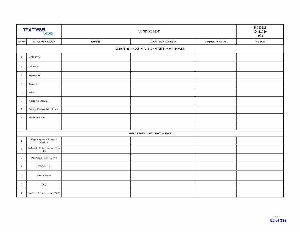
1 ABB LTD
2 Schneider
3 Siemens AG
4 Emerson
5 Fisher
6 Yokogawa India Ltd
7 Samson Controls Pvt Ltd India
8 Masoneilan India
1 Lloyd Register of IndustrialServices
2 Technische Ulierwachungs Verein(TUV)
3 Det Norske Veritas (DNV)
4 AIB-Vincotte
5 Bureau Veritas
6 SGS
7 American Bureau Services (ABS)
THIRD PARTY INSPECTION AGENCY
ELECTRO-PENUMATIC SMART POSITIONER
30 of 31
52 of 388

P.013828 D 11040
002
Sr. No. NAME OF VENDOR ADDRESS DELHI / NCR ADDRESS Telephone & Fax.No. Email-Id
VENDOR LIST
8 Velosi Certification Services
Note : 1) The details of Vendors indicated in this list are based on the information available with TE, Contractor shall verify capabilities of each vendor for producing the required quantity with. Consultant does not Guarantee any responsibility on the performance of the Vendor, it is
31 of 31
53 of 388

Page 1 of 21
HMEL CONNECTIVITY PIPELINE PROJECT, BHATINDA
TRACTEBEL ENGINEERING PVT. LTD.
PARTICULAR TECHNICAL SPECIFICATION
FOR
PIPELINE VALVES
00 16.04.2019 Issued as RFP MK MS SKH
Rev. Date Description Prepared by Checked by Approved by
PTS – PIPELINE VALVES P.013828
D 11077
213
54 of 388

PTS – PIPELINE VALVES P.013828
M 11077
213
Rev. 00 HMEL Connectivity Pipeline Project.
Page 2 of 21
TABLE OF CONTENTS
1. SCOPE ........................................................................................................................................ 3
2. DEFINITIONS ............................................................................................................................. 3
3. PRELIMINARY STATEMENT ....................................................................................................... 3
4. GENERAL .................................................................................................................................... 4
5. CODES, NORMS AND STANDARDS ............................................................................................. 4
6. DESIGN AND CONSTRUCTION ................................................................................................... 4
7. MATERIALS .............................................................................................................................. 10
8. FABRICATION AND TEST .......................................................................................................... 11
9. MARKING ................................................................................................................................. 15
10. INSPECTION ............................................................................................................................. 15
11. PAINTING AND COATING ......................................................................................................... 17
12. SPARES AND ACCESSORIES ..................................................................................................... 17
∑ ∑ ∑
55 of 388

PTS – PIPELINE VALVES P.013828
M 11077
213
Rev. 00 HMEL Connectivity Pipeline Project.
Page 3 of 21
1. SCOPE
This Document (PTS - Particular Technical Specification for – PIPELINE VALVES) lists the Specification for
Manufacturing of Ball Valves, for the pipeline project for the service of natural gas.
The present specification has to be read in conjunction with General Technical Specification
70000/740/GTS/402 rev. 7 (The GTS) which it amends and/or complements.
The present specification can confirm, complete or modify certain sections/paragraphs of said «General
Technical Specification». The PTS will govern the requirements for all such sections.
Add:
The present Particular Technical Specification relates to the manufacture of “Pipeline Ball Valves” (for
above and underground) for the pipeline project for the service of natural gas.
2. DEFINITIONS
Client shall mean GAIL (I) Limited
Manufacturer means the Manufacturer of the Valves as well as its sub contractors.
EPC Contractor/Contractor The party which carries out all or part of Engineering, Procurement,
Construction, Pre-commissioning & Commissioning of the project. It shall
mean EPC Contractor in the present context.
Inspection Agency or Third means the Inspection Agency to be appointed by the EPC Contractor
Party Inspection Agency (TPIA)
Consultant /Owner Shall means TRACTEBEL Engineering Pvt. Limited / The entity
Representative of the purchaser or the company nominated by the purchaser to design the
natural gas transport or distribution system and to specify the equipment.
PTS means the present “Particular Technical specification P.013828 D 11077 213”
and all its appendices, if any.
GTS means <<General Technical Specification 70000/740/GTS/402 rev. 7 >> and all documents it refers to.
3. PRELIMINARY STATEMENT
Add:
• In case of conflict between the requirements in technical documents, the most stringent requirements
shall apply.
56 of 388

PTS – PIPELINE VALVES P.013828
M 11077
213
Rev. 00 HMEL Connectivity Pipeline Project.
Page 4 of 21
• A valid copy of API 6D monogram/certificate shall be included in the offer.
Modify para 10 & 11: • For any control, test or examination required under the supervision of the Authorised Control authority
(LOFC Intervention points included), the latter shall be informed in writing FIVE (5) working days in advance
by the Manufacturer (Fifteen working days in case of supply of foreign origin) about place and time with a copy
to the Client/Engineer. Wages and travel expenditure of the Authorised Control Authority are at the Client’s
expenses.
• As the manufacturing is to be carried out under LOFC concept, the Manufacturer shall send for approval a
List of Operation in Manufacturing and Control (see annex 1) to the Authorised Control Authority and Client,
TEN (10) working days before manufacturing. This list shall be in conformity with the annex 1 to this
document. Before starting any manufacturing, the Manufacturer shall be in possession of this approved
document, filled in with all intervention points.
4. GENERAL
Add:
Valve design shall meet the requirements of API Specification 6D and shall be suitable for the service
conditions indicated in the Valve Data Sheet. The ASME Boiler & Pressure Vessel Code, Section VIII,
Division 1 shall be used to design the valve body.
Allowable stress requirements shall comply the provisions of above code. In addition, corrosion allowance
indicated in Valve Data Sheet shall be considered in valve design.
The manufacturer shall have valid license to use API monogram on valves manufactured as per API 6D. The
ball valves shall be bi-directional.
5. CODES, NORMS AND STANDARDS
Add:
API 598 : Valve Inspection and Testing
ISO/DIS 14313 : Petroleum and Natural Gas Industries - Pipeline Transportation Systems –
Pipeline valves
Note:
In case of conflict between the requirements of this specification, Codes, Standards and Specifications referred in
above, the most stringent requirement specification shall govern.
6. DESIGN AND CONSTRUCTION
57 of 388

PTS – PIPELINE VALVES P.013828
M 11077
213
Rev. 00 HMEL Connectivity Pipeline Project.
Page 5 of 21
6.2 Design
6.2.2 Welding ends
Add:
The valve manufacturer shall supply all butt weld valves with a welded pups/Transition piece at both ends which
shall be considered as an integral part of the valve & hence such as strength test, hydrostatic test & Leak test
should be done with pup-piece/transition piece weld on valve.
The chemical composition of the steel of the Pup/Transition piece meets the following requirements
Maximum limit of chemical elements which may be used in material under this Particular Technical
Specification.
% maximum % maximum % maximum
C 0.230 Mn 1.60 Si 0.50
P 0.030 S 0.025 Nb. 0.080
V 0.120 Mo 0.250 Nt 0.015
Alternate alloy elements may be used but they shall be discussed with the user prior to delivery of the material.
This table is not intended to represent the composition of any heat of steel, but merely to record the maximum
permissible amounts of one element. The combination of elements of any heat must conform to the carbon
equivalent, computed like following:
Carbon equivalent shall be computed by "check analysis", the following equation is applicable :
and shall not exceed 0.40 % . The CE (IIW) limits shall not apply if C< 0.12% and shall not exceed 0.43
For each heat the manufacturer shall analyse the following elements: C, Mn, Si, P, S, Nb, V, Cr, Mo, Ni and Cu.
The intentional addition of elements other than those specified is not permitted unless agreed up by the Client.
In any case, for unintentional additions, the following limitations shall be respected:
Cr < 0.15% Mo < 0.05% Cu < 0.20%
58 of 388

PTS – PIPELINE VALVES P.013828
M 11077
213
Rev. 00 HMEL Connectivity Pipeline Project.
Page 6 of 21
Ni < 0.30% Co < 0.01% Al < 0.07%
The content of N total (Nt) may be up to 0.0150% and must be guaranteed by the manufacturer. If the
manufacturer cannot give any guaranty of N content, he shall analyse this element.
The total content for Nb + V will be limited to 0.150%.
In grades X42 through X70 for each reduction of 0.01% below the maximum carbon content, an increase of
0.05% manganese above the specified maximum is permissible, up to a maximum of 1.70%.
The choice and use of alloying elements made from high strength low alloy steels to give the tensile properties of
API 5L Gr. X70 (in table hereafter), is of the responsibility of the manufacturer.
Symbol Yield Strength (min.) Tensile Strength (min.) Elongation in 2 in.
Ksi Mpa Ksi Mpa Min. percent
X70 70.30 485 82.70 570 20
The ratio of effective yield strength to effective tensile strength of the steel shall not exceed 0.90 for material of
SMYS 70300 psi. For SMYS below 70300 psi this ratio shall not exceed 0.85.
If the butt-welding end of the valve has a thickness and/or a steel grade not equal to the connecting pipe, butt-
welding ends shall be in accordance with any of the suggestive figures given in Appendix I of ASME B 31.8 or
an appropriate combination selected by the valve manufacturers to ensure that availability of uniform pig passage
without sacrificing pressure-temperature design requirement.
Butt weld end valves shall be provided with pup piece. Pup piece length shall be of at least 2.0 D for size below
6” and 300 mm for 6” and above size valves upto 18”.
Size of Ball valve (NB) Pup Piece length (mm)
Below 6” 2.0 D
6” & Above upto 18” 300
No repair is permitted on pup pieces. 100 % UT shall be performed on pup pieces.
Thickness of Pup Piece shall be determined by the Vendor as per Code requirements. The pipe end of the Pup
Piece shall match the Material, diameter and thickness of line pipe where the valve is required to be welded.
Table below indicate the size, thickness, material of the line pipe for various sizes of Ball valves:
Size of Ball valve Material of Thickness Remarks
59 of 388

PTS – PIPELINE VALVES P.013828
M 11077
213
Rev. 00 HMEL Connectivity Pipeline Project.
Page 7 of 21
3” to 16” ASTM A 333 Gr. 6 SCH. 80 Seamless (LTCS)
½” to 2” ASTM A 333 Gr. 6 SCH. 160 Seamless (LTCS)
The Valve Manufacturers shall submit all necessary details regarding welding of BW end of valve with
Line pipe along with calculation for provided thickness for approval of Owner/Owner’s representative.
The Charpy V-notch impact testing of pup piece (for API 5L material) as indicated in data sheet shall be carried
out as following:
Location Impact Test
Temp.
Impact Energy Absorption Value
Avg. Value Individual Value
For Base
-20 °C 35 J
28 J
0 °C 100 J
80 J
For Weld & HAZ Metal
I
-20 °C 35 J
28 J
0 °C 40 J
32 J
In addition to above the Charpy V-notch impact testing of pup piece, Valve body and other pressure containing
parts of valve (for CS or LTCS steel material) as indicated in data sheet / piping material specification shall be
carried out as per following requirements
Material Test Temperature Energy Absorption Value
Carbon Steel -20 Deg. C Individual 28J & Average 35J
Low Temperature Carbon Steel
Material
-20 Deg. C Individual 28J & Average 35J
Material Standard’ impact test requirements
temperature or - 45 Deg. C whichever is lower
Material Standard’s Impact test requirement
The pup piece shall be subjected to all the testing (Charpy, Tensile, Hardness, NDT etc.) requirements as
mentioned in QAP. Inspection frequency, acceptance criteria & reference standards shall be as per
applicable specifications/QAP.
6.2.4 Design features
Add in Para 1:
60 of 388

PTS – PIPELINE VALVES P.013828
M 11077
213
Rev. 00 HMEL Connectivity Pipeline Project.
Page 8 of 21
For above ground valves, body design shall be either fully welded or bolted type. For buried valves, valve body
design shall be fully welded type only. Valve body joints with threads are not permitted. In the valve body outlets
also, threading is not permitted.
Ball shall be of single piece, solid type construction.
The full bore valve shall provide an unobstructed profile for pigging operations in either direction. Full bore
valves shall be designed to minimize accumulation of debris in the seat ring region to ensure that ball movement
is not impeded. Also, when the full bore ball valve is in fully open position, the ball shall not obstruct the passage
of flow/pig run. Manufacturer shall demonstrate the same through manual and actuated operation.
Modify:
For 4” & above size, valve shall be trunnion mounted ball valve. All trunnion mounted ball valve shall be fitted
with following devices:
Double piston effect: when the pressure is applied to one side, let us say upstream” side, and when upstream ball
seat is leaking, transfer pressure shall have a positive shut-off effect on the downstream seat (acting, for instance,
on the back face of this seat) and thus reinforcing the global tightness of the valve. (Not applicable)
Add :
Vent, sealant etc. shall be adequately supported on the stem and body using clamps
Corrosion allowance of ball valve shall be 1.6mm
For valves with primary metal to metal contact and secondary soft seats, O-rings or other seals if used for drip
tight sealing shall be encased in a suitable groove in such a manner that it cannot be removed from seat ring and
there is no extrusion during opening or closing operation of valve at maximum differential pressure
corresponding to valve class rating. The seat rings shall be so designed as to ensure sealing at low as well as high
differential pressures.
For soft seated valves seat rings may be provided with soft insert. The same shall be positively locked in position.
All such ball valves shall comply fire safe design and qualified by fire testing as per API 6FA specification for
Fire test for valves.
Valves shall be designed to withstand a sustained internal vacuum of at least 1 (one) milli-bar(a) in both open and
closed positions.
Valve design shall be such as to avoid bimetallic corrosion between carbon steel and high alloy steel
components. Suitable insulation shall be provided, if required.
61 of 388

PTS – PIPELINE VALVES P.013828
M 11077
213
Rev. 00 HMEL Connectivity Pipeline Project.
Page 9 of 21
Valve design shall ensure repair of stem seals/packing under full line pressure.
Valve shall be provided with ball position indicator and stops of rugged construction at the fully open and fully
closed positions
6.2.5 Auxiliary Connection
Add / Modify :
Schematic for drain vent and stem /Sealant point for “Above Ground Installation” and “Under Ground
Installation” refer Appendix – I.
6.2.6 Stem extension for underground valve
Add:
Stem extension material shall be equivalent to stem material or as indicated in the data sheets for below ground
valves. Stem shall be single piece construction & no joints are permitted. The length of stem extension shall be as
indicated in the MR.
Valves provided with stem extension shall have water proof outer casing. Length of stem extension shall be as
indicated in Valve Data Sheet. The length indicated corresponds to the distance between centreline of the valve
opening and the top of mounting flange for valve operating device (gear operator/power actuator as applicable).
Outer casing of stem extension shall have ⅜”" or ½" NPT plugs at the top and bottom, for draining and filling
with oil to prevent internal corrosion. Outer casing material shall be ASTM A333 Gr. 6 & thickness shall be
minimum Sch 160 for 2” and below.
6.3 OPERATION
6.3.1 Add:
Valves shall have a Gas over Oil (GOO) actuator or manual operator or hydraulic operator as indicated in the
Valve Data Sheet. All mainline valves shall be equipped with Gas over Oil (GOO) actuators except where
specifically indicated otherwise. Valves of size, DN upto 100 mm (4”) shall be wrench operated, valves of size DN
150 mm (6”) to DN 300 mm (12”) shall be gear operated and valves of sizes above DN
300 mm (12”) shall be hydraulic operated unless otherwise indicated in the valve data sheets. Actuated valve shall
also have hand wheel for manual operation. Each wrench-operated valve shall be supplied with wrench. Valve
design shall be such that damage due to malfunctioning of the operator or its controls will only occur in the
operator gear train or power cylinder and that damaged parts can be replaced without the valve cover being
removed.
62 of 388

PTS – PIPELINE VALVES P.013828
M 11077
213
Rev. 00 HMEL Connectivity Pipeline Project.
Page 10 of 21
The Gas over Oil (GOO) actuator shall be in accordance with the specification issued for the purpose and as
indicated in the Valve and Actuator Data Sheet. Operating time shall be as indicated in Process Data Sheets for
valves / Material Requisition. Valve operating time shall correspond to full close to full open/ full open to full
close under maximum differential pressure corresponding to the valve rating. For actuated valves, the actuator’s
rated torque output shall be 1.25 times the break torque required to operate the ball valve under the maximum
differential pressure corresponding to the Valve Class Rating.
Valves shall be subjected to Operational Torque Test as per API 6D (Annexure B) under hydraulic pressure equal
to maximum differential pressure corresponding to the applicable ANSI class rating of valve.
6.3.2 Add :
Manufacturer shall also indicate the number of turns of hand wheel in case of gear operators (along with their
offer) required for operating the valve from full open to full close position.
When indicated in Material Requisition, valves shall have locking devices to lock the valve either in full open
(LO) or full close (LC) positions. Locking devices shall be permanently attached to the valve operator and shall
not interfere with operation of the valve.
6.3.9 Add:
No casting is permitted for stem and stem extension material of all valves. Valve stem shall be capable of
withstanding the maximum operating torque required to operate the valve against the maximum differential
pressure corresponding to applicable class rating for a minimum of 500 open-close-open cycles for a design life of
40 years. The combined stress shall not exceed the maximum allowable stresses specified in ASME section VIII,
Division 1. For power actuated valves, the valve stem shall be designed for maximum output torque of the selected
power actuator (including gear box, if any) at valve stem
7. MATERIALS
7.2 Pressure Retaining Parts
Modify clause no. 7.2.1 as below:
Bodies, including end flanges and welding ends (other than for field welding), bonnet and covers of valves shall be
made in material conforming to API 6D spec. (or another material specification accepted by the Client/Engineer)
and be furnished with certificates EN 10204-3.2 stating the quality, the mechanical properties (yield strength,
tensile strength, percent elongation, impact test value at the temperature specified under per Section 8.4.2 of
GTS) the chemical analysis, the manufacturing process and the marking (e.g. the heat number) of the steel. These
certificates shall be added to the CMTR.
7.2.4 Modify:
• The carbon equivalent shall not exceed 0.43
63 of 388

PTS – PIPELINE VALVES P.013828
M 11077
213
Rev. 00 HMEL Connectivity Pipeline Project.
Page 11 of 21
• Add:
In case of LTCS material of Ball and Seat Ring, ENP coating of 75 micron shall be applied as per ASTM
B733-15. Minimum hardness of plating 48-50 HRC (as plated) and 62-63 HRC (after heat treatment).
• Modify:
The ratio of yield strength to tensile strength shall not exceed 0.90.
7.3 Bonnet, Cover and Body Bolting
Modify first paragraph as below:
Bonnet flange cover and body bolting shall be in conformance to ASTM A320 Gr. L7. Nuts shall conform to
ASTM A194 Gr.4/Gr. 7. All bought out items shall be procured with certificates EN 10204-3.2 including Valve
actuator. These certificates shall be added to CMTR.
Add:
All studs and nuts shall be hot dip zinc coated.
7.4 Non – Metallic Parts
Add:
Non-metallic parts of the valves (including O-rings, soft seals etc.) intended for hydrocarbon gas service shall be
resistant to explosive decompression.
7.6 Sour Gas Service
Not Applicable
8. FABRICATION AND TEST
Prior to manufacturing a meeting shall be organised between EPC Contractor, vendor/contractor, TPIA appointed
by EPC Contractor and Owner.
8.1 Welding Fabrication
Replace third point by:
The joints shall be furnished in accordance with the requirements of Section VIII of ASME Boiler and
Pressure Vessel Code - Division 1 and Section IX.
64 of 388

PTS – PIPELINE VALVES P.013828
M 11077
213
Rev. 00 HMEL Connectivity Pipeline Project.
Page 12 of 21
Add:
Vendor shall provide detail instruction for carrying out welding; pre heating etc and testing of weld joints between
pipe and valves at site. Vendor shall depute engineer for welding instruction at site
8.3 Heat Treatment
Add
Chemical composition and mechanical properties shall be checked as per this specification and relevant material
standards, for each heat of steel used. All testing frequency shall be as per Inspection & Test Plan/ QAP. Heat
treatment chart for forging material shall be witness & start/stop time signed by TPIA.
8.4.2 Impact test
Charpy V-notch test on each heat of base material shall be conducted as per API 6D-Clause 8.5, for all pressure
containing parts such as body, ball, seat, stem, end flanges and welding ends as well as bolting material for
pressure containing parts. The Charpy V-notch test requirements of applicable material standard shall be
conducted. The impact test temperature shall be lower of the temperature specified in material standard and -45C.
8.5 Non Destructive Examinations (NDE)
The following non destructive examination shall be performed by the Manufacturer under the supervision of
the TPIA and the certificates shall be added to the CMTR.
8.5.1 List of NDE
Add :
• Body castings of all valves shall be radiographically examined as per ASME B16.34. Procedure and
acceptance criteria shall be as per ASME B16.34. The extent of the radiography shall be 100% for
all class rating of all sizes.
• Radiography shall be performed after the final heat treatment also.
• Internal surfaces for all castings shall be 100% wet magnetic particle inspected. Method and
acceptance shall comply with ASME B16.34.
• All valves made by forgings shall be ultrasonically examined in accordance with the procedure and
acceptance standard of Annexure E of ASME B16.34. Body fabricated from plates is not acceptable.
• Internal surfaces of all forgings shall be 100% wet magnetic particle inspected. Method and
acceptance shall comply with ASME B16.34.
65 of 388

PTS – PIPELINE VALVES P.013828
M 11077
213
Rev. 00 HMEL Connectivity Pipeline Project.
Page 13 of 21
• Full inspection by radiography shall be carried out on all welds of pressure containing parts including
• 100% radiography of the weld joint between valve and pup pieces. Acceptance criteria shall be as per
• ASME B31.8 and API 1104.
• Welds & valve body weld joints, which in Company's opinion cannot be inspected by radiographic
methods, shall be checked by ultrasonic or magnetic particle methods and acceptance criteria shall
be as per ASME Sec. VIII, Division 1, Appendix 12 and Appendix 6 respectively.
66 of 388

PTS – PIPELINE VALVES P.013828
M 11077
213
Rev. 00 HMEL Connectivity Pipeline Project.
Page 14 of 21
8.6 PRESSURE TESTING
8.6.5 Add In addition to pneumatic testing and functional testing shall be carried out at 90 bar (g) and 7 Bar for 600# &
300 # pressure rating valves, using nitrogen for 5 minutes.
In addition to above the helium leak test shall be carried out as per ASME Sec. V, Subsection A, Article 10
(Detector Probe Technique), Appendix IV. Helium leak testing shall be done at 25% of rated pressure for 30 mins.
8.7 OPERATIONAL TORQUE TEST
GOO actuated & Hydraulic operated valves shall be tested after assembly of the valve and actuator, at the valve
Manufacturer’s works. At least five Open-Close-Open cycles without internal pressure and five Open-Close-Open
cycles with maximum differential pressure corresponding to the valve rating shall be performed on the valve
actuator assembly. The time for Full Open to Full Close shall be recorded during testing. If required, the actuator
shall be adjusted to ensure that the opening and closing time is within the limits stated in Process Data Sheets for
valves.
Hand operator provided on the actuator shall also be checked after above testing, for satisfactory manual over-ride
performance.
The above tests shall be conducted on all valves.
8.9 ANTI-STATIC DEVICE TESTING
“If requested in the purchase order, all ball valves shall be submitted of to an anti-static electricity testing in
accordance with BS 5146 and this certificate shall be added to the CMTR”.
Subsequent to successful testing as specified in above clause, one (1) valve per size out of the total ordered
quantity shall be randomly selected by the EPC Contractor / Owner / Owner’s Representative for cyclic testing as
mentioned below:
a) The valve shall be subjected to at least 100 Open-Close-Open cycles with maximum differential pressure
corresponding to the valve rating.
b) Subsequent to the above, the valve shall be subjected to hydrostatic test and supplementary air seat test.
Air seat test shall be carried out at 7 barg and not 6 barg as mentioned in GTS.
67 of 388

PTS – PIPELINE VALVES P.013828
M 11077
213
Rev. 00 HMEL Connectivity Pipeline Project.
Page 15 of 21
In case this valve fails to pass these tests, the valve shall be rejected and two more valves of same size shall be
selected randomly and subjected to testing as indicated above. If both valves pass these tests, all valves
manufactured for that size (except the valve that failed) shall be deemed acceptable. If either of the two valves fails
to pass these tests, all valves of that size shall be rejected or each valve shall be tested at the option of
manufacturer.
Previously carried out test of similar nature shall be considered acceptable if the same has been carried out by
Manufacturer in last two years. Valves of same size and rating previously tested shall be qualified.
9. MARKING
Add:
All valves shall be marked as per API 6D. The units of marking shall be metric except nominal diameter, which
shall be in inches.
Valve ends shall be suitably protected to avoid any damage during transit. All threaded and machined surfaces
subject to corrosion shall be well protected by Moly coat type grease or other suitable material. All valves shall be
provided with suitable protectors for flange faces, securely attached to the valves. Bevel ends shall be protected
with metallic or high impact plastic bevel protectors.
All sealant lines and other cavities of the valve shall be filled with sealant before shipment
On packages, following shall be marked legibly with suitable marking ink:
a) Order Number
b) Manufacturer's Name
c) Valve size and rating
d) Tag Number
e) Serial Number
10. INSPECTION
10.1 Information
Add:
In case of supply from foreign origin, the Manufacturer shall inform the Control Authority min. fifteen (15)
working days in advance of any intervention required by this specification and shall send a copy of it to the
Client/Engineer (by fax).
68 of 388

PTS – PIPELINE VALVES P.013828
M 11077
213
Rev. 00 HMEL Connectivity Pipeline Project.
Page 16 of 21
Valve’s certification requirements shall comply with European Standard EN 10204 (latest edition) 3.2Certificate.
Add:
PACKING
Ball valves are to be suitably packed, crated (seaworthy crate in the case of foreign vendors) and handled properly
to prevent damages or deteriorations during transportation by sea (in the case foreign vendors) and road to the
designated ware houses (as detailed in the commercial volume of the tender).
Vendors shall submit drawings and details of the proposed packing / crating method clearly indicating the
following:
• Secure bolting arrangement of the ball valve to the robust base of the crate for packing.
• Lateral staying arrangement to prevent movement of the valve inside the crate resulting damage during
transportation and handling.
• Also all extended parts such as drain and vent piping shall be securely supported to the valve body to
prevent damage during transportation and also subsequent installation and use in operations
10.2 Documents
Add:
EPC shall obtain the following documents from manufacturer and verify before placement of order:
• General arrangement/ Sectional drawing & blow-up drawing of seat assembly shall be submitted.
• Number of turns for Gear Operated valves shall be indicated in the GA or shall be furnished separately.
69 of 388

PTS – PIPELINE VALVES P.013828
M 11077
213
Rev. 00 HMEL Connectivity Pipeline Project.
Page 17 of 21
• Torque curves for the power actuated valves along with the break torque and maximum allowable stem
torque.
• Copy of valid API 6D Certificate.
In case of soft seated valves, copy of Fire Safe Test certificate of qualifying valve as per API 6FA carried out in
last 10 years shall be furnished.
Details of support foot including dimensions and distance from valve centerline to bottom of support foot.
11. PAINTING AND COATING
Following coating specification shall be followed:
11.1 Underground Valves:
The external coating for underground valves shall be made of solvent free PUR / min. 1000 microns
(Final Paint DFT) thickness in two layers Polyurethane as per code DIN 30677/2 (Type DIN 30677/2-
PUR-50) alternatively high build epoxy corrosion protection coating with minimum 500 microns final
DFT as per DIN 30677/2 is also acceptable.
For repair it would be as per manufacturer’s recommendations which have to be approved by
Owner/Engineer.
11.2 Aboveground Valves: The surface of the valve will be shot-blasted SA 2 1/2 (Swedish standard SIS 055900). Before painting,
the valve shall be cleaned from grease and dirt. The painting shall be as per ISO12944-5-2007 (Table
A-5) Paint System No. S5.14 with durability C-5 (I) Very High Industrial. The final paint DFT shall be
minimum 300 micron.
The nature of the products shall be specified in the offer and shall guarantee a corrosion protection for a
storage period in a shop for at least one year.
Painting in accordance with Client/Engineer's specifications.
Painting and coating procedures shall be submitted for approval before manufacturing to the Control
Authority and to the Client / engineer.
12. SPARES AND ACCESSORIES
70 of 388

PTS – PIPELINE VALVES P.013828
M 11077
213
Rev. 00 HMEL Connectivity Pipeline Project.
Page 18 of 21
All spares required for start-up and commissioning of the valve shall be supplied along with the valve.
Manufacturer shall furnish list of recommended spares and accessories required for two years of normal
operation and maintenance of valves and price for such spares shall be quoted separately.
∑ ∑ ∑
71 of 388

PTS – PIPELINE VALVES P.013828
M 11077
213
Rev. 00 HMEL Connectivity Pipeline Project.
Page 19 of 21
72 of 388

PTS – PIPELINE VALVES P.013828
M 11077
213
Rev. 00 HMEL Connectivity Pipeline Project.
Page 20 of 21
73 of 388

PTS – PIPELINE VALVES P.013828
M 11077
213
Rev. 00 HMEL Connectivity Pipeline Project.
Page 21 of 21
74 of 388

PTS – PIPELINE VALVES P.013828
M 11077
213
Rev. 0 - 16.04.2019 Filtertion, Metering & Pressure Reduction Skids for HMEL
Connectivity Project.
Page 22 of 21
Σ Σ Σ
75 of 388

PTS-STATION PIPE
P.013828
D 11077
214
Page 1 of 14
HMEL CONNECTIVITY PIPELINE PROJECT, BHATINDA
TRACTEBEL ENGINEERING PVT. LTD.
PARTICULAR TECHNICAL SPECIFICATION
FOR
STATION PIPE
(ASTM A 333 Gr. 6 and
API 5L Gr. X52, X65 & X70, PSL 2)
00 16.04.2019 Issued as RFP MK MS SKH
Rev. Date Description Prepared by Checked by Approved by
76 of 388

PTS-STATION PIPE
P.013828
D 11077
214
Rev.00 HMEL Connectivity Pipeline Project. Page 2 of 14
TABLE OF CONTENTS
1. GENERAL .................................................................................................................................... 3
2. DESIGN AND CONSTRUCTION ................................................................................................... 5
3. MATERIALS ................................................................................................................................ 5
4. PRELIMINARY CONDITIONS FOR UPGRADING TO 3.2. CERTIFICATE...................................... 6
5. UPGRADING TESTS .................................................................................................................... 8
6. INSPECTION AND CERTIFICATION ......................................................................................... 11
7. INSPECTION BY CONTROL OPERATIONS: L.O.C. .................................................................... 12
8. CORROSION INSPECTION ....................................................................................................... 13
∑ ∑ ∑
77 of 388

PTS-STATION PIPE
P.013828
D 11077
214
Rev.00 HMEL Connectivity Pipeline Project. Page 3 of 14
1. GENERAL
This specification describes the requirement of station pipes to be used for installation at proposed station
facilities along the above pipelines, viz. the dispatch station, SV station, receiving station.
This specification also describes the examinations and upgrading tests to be performed on carbon steel pipes
taken out of stock.
The pipes have to be delivered in accordance with this particular specification:
Codes, Norms and standards (latest revision) listed below (but not limited to):
ANSI B31.8 Gas transmission and distribution piping systems
ANSI B16.25 Butt welding ends
ANSI B36.10 Welded and seamless wrought steel pipe
ASTM A 333 Seamless and welded steel pipe for low temperature service
ASTM A 370 Mechanical testing of steel products
ASTM E 112 Standard test methods for determining the average grain size
ASME Boiler and Pressure Vessel code
EN 10204 Metallic Products : Type of Inspection Documents
ISO 9001 Quality management standard
ISO 148 Determine the impact strength of steel and energy absorbed by Chapy V-notch.
API 5L Specification for line pipe
The present specification can confirm, complete or alter certain criteria / requirements / acceptance norms
of applicable codes, standards and/or specifications.
In his offer, the vendor/contractor shall specify all proposed modifications or alternatives to the present
specification. In all cases, each modification has to be submitted to the Owner / Owner’s representative for
acceptance and approval. The complete upgrading cycle shall be supervised by the TPIA. All
consequences after eventual order, for non respect of this obligation shall be to the manufacturer's cost and
responsibility.
Before the order is placed, a technical audit could take place with EPC contractor or client.
The manufacturer's specification of the steel, the manufacturing procedure itself and the laboratories in
which testing takes place, shall be approved and registered by the EPC contractor/ Owner /Owner’s
representative.
The TPIA shall verify the control equipment of the vendor, its calibration and the points at which it is
located. If during the control of the pipes certain problems arise the TPIA may demand supplementary
tests.
78 of 388

PTS-STATION PIPE
P.013828
D 11077
214
Rev.00 HMEL Connectivity Pipeline Project. Page 4 of 14
At all times while work on the contract of the purchaser is being performed, the inspector representing the
purchaser shall have free entry to all parts of the manufacturer's facilities and those of all subcontractors,
who are involved in the manufacturing and testing of the pipes. All reasonable facilities shall be afforded to
the inspector to satisfy him that the product is being furnished in accordance with these specifications.
All tests and inspections called for by these specifications will be made in the manufacturer's plant prior to
shipment and at the manufacturer's expense, unless otherwise stated, and shall be conducted so as not to
interfere unnecessarily with the operations of the manufacturer's plant. The manufacturer shall notify the
purchaser prior to completion or shipment of all items requiring such inspection.
Eventual interpretations and deviations to this specification by the Manufacturer shall be requested by
writing in his offer with detailed justification and approved by the Owner / Owner’s representative before
eventual order to the Manufacturer. The latter is responsible and shall indemnify the Owner / Owner’s
representative for any damage resulting from the non-respect of this obligation.
An approval of documents can never be considered as an acceptance of deviations or relaxations to
requirements. A deviation is only possible after specific request to the purchaser and its approval.
A valid copy of the ISO 9001 certificate shall be included in the offer.
In case the Pipe is procured from manufacturer, the manufacturer shall inform the TPIA / EPC contractor
MIN. 5 working days in advance of any control test or examination under the supervision of the TPIA
required by this specification, and shall send a copy (fax/E-mail) of it to the EPC contractor / Owner’s
representative.
The Manufacturer shall send for approval a List of Operation in Manufacturing and Control to the Owner /
Owner’s representative, TEN (10) working days before manufacturing. Before starting any manufacturing,
the Manufacturer shall be in possession of this approved document, filled in with all intervention points.
Glossary
Client / Owner Shall mean GAIL ( I) Limited
Manufacturer Means the Manufacturer of the station piping.
EPC Contractor / Contractor The party which carries out all or part of Engineering,
Procurement, Construction, Pre-commissioning & Commissioning
of the project. It shall mean EPC Contractor in the present context.
Third Party Inspection
Agency (TPIA)
Means the Inspection Agency to be appointed by the EPC
contractor
Consultant / Owner
Representative
Shall means TRACTEBEL Engineering Pvt. Limited / The entity
of the purchaser or the company nominated by the purchaser to
design the natural gas transport or distribution system and to
specify the equipment
PTS Means the present <<Particular Technical Specification P.013828
D 11077 214>> and its entire appendix, if any.
79 of 388

PTS-STATION PIPE
P.013828
D 11077
214
Rev.00 HMEL Connectivity Pipeline Project. Page 5 of 14
2. DESIGN AND CONSTRUCTION
a) The pressure temperature ratings of the pipes are in accordance with B31.8; the dimension standard
shall be in conformance to ANSI /ASME B 36.10.
b) The temperature range as follows:
• For above ground Services – LTCS : -45°C to +65°C
• For above ground Services – CS : -20°C to +65°C
• For Underground Services : -20°C to +60°C
The design pressure is 92 Barg.
c) Wall thickness shall meet the following requirements :
� The maximum allowable stress in the base material and in the weld shall be equal to fifty per cent
(50%) of the minimum yield strength guaranteed by the specification of the steel used.
d) The specified pipe wall thickness/schedule and grade (with reference to the equivalent grade in ASTM
spec. or API 5L spec.) with which the pipe is intended to be used is specified in the data sheet/piping
class.
e) The design shall take into consideration performance requirements prescribed in paragraph 2.f.
f) All pipe under this specification shall be designed to withstand a field hydrostatic test pressure with
non corrosive water, after installation, during 24 hours at a following pressure level :
Minimum: P = 1.4 MOP
Maximum: P = 1.5 MOP
Where:
P = hydrostatic test pressure, bar,
MOP = Maximum Operation Pressure
3. MATERIALS
a) The steel used in the manufacture of pipe shall be in conformance to the ASTM / API5L standard.
b) The chemical composition of the steel shall meet the requirements of T a b l e 1 of this specification.
c) The steel used has tensile properties conforming to the requirements prescribed in the ASTM
standard. d) The ratio of yield strength to tensile strength shall not exceed 0.85 for ASTM A 333
Gr.6 Pipes and 0.90 for API 5L Gr.X65/70 PSL 2 Pipes.
d) The steel shall be fully killed, fine grain practice.
e) The steel used shall be suitable for field welding to other fittings, pipes, flanges, or valves
manufactured under ASTM specifications A333, A350, A352, A381, A420, A694, A707 or API
standards specifications 5L, 6D, 605 or MSS standards SP-44, SP-72, SP-75, EN10208-2 in line
with the Piping Specification attached with the tender document.
80 of 388

PTS-STATION PIPE
P.013828
D 11077
214
Rev.00 HMEL Connectivity Pipeline Project. Page 6 of 14
f) If preheating of the material is required to ensure proper weld ability under normal field conditions,
the manufacturer shall state so in the offer, specifying preheat requirements and if accepted by
the purchaser, this shall be permanently indicated on the pipe.
g) The manufacturer of pipe must deliver a certificate EN 10204 3.2 stating the quality, the
mechanical properties (yield strength, tensile strength, percent elongation, impact test as per below
table, the chemical analysis, the process of manufacture and the marking (for example the heat
number of material) of the steel.
A new chemical analysis (upgrading) shall be done on a specimen of pipe in presence of the
Control Authority; one per heat number, see par. 5.3.
h) Chemical composition :
For each heat the manufacturer shall check a chemical analysis of the steel.
� Check analysis : carbon equivalent shall be computed by the following equation :
C E CMn Cr Mo V Ni Cu
. .= + ++ +
++
6 5 15
and shall not exceed 0.43
4. PRELIMINARY CONDITIONS FOR UPGRADING TO 3.2. CERTIFICATE
Before proceeding to any qualification tests, the pipes shall meet following requirements.
4.1. Material
Carbon steel piping to be supplied according to ASTM A 333 Gr. 6 or API 5L Gr.X52/ X65/ X70 as per
PMS.
4.2. Origin of pipes
The origin of pipes shall be mentioned.
The Engineer or/and the Control Authority reserves the right to approve or refuse the origin of pipes.
4.3. Identification
All pipes shall bear the original mill identification.
The marking shall be legible and shall include as a minimum:
� Manufacturer's name or brand.
� ASTM specification.
� Steel grade,
� Heat number or identification number traceable to the certificate.
� Size and schedule number.
81 of 388

PTS-STATION PIPE
P.013828
D 11077
214
Rev.00 HMEL Connectivity Pipeline Project. Page 7 of 14
� Process of manufacture.
4.4. Certification
The pipes shall have been manufactured according to material data sheets to ASTM A 333 Gr. 6 or API 5L
Gr.X 52/ X65/ X70.
A mill certificate according to EN 10204 3.2 shall be supplied and shall mention as a minimum:
� The ASTM specification and steel grade.
� The type of pipe manufacturing process.
� The heat and/or identification number.
� The type of heat treatment.
� The chemical analysis of the heat.
� The mechanical properties as required by the ASTM specification.
The marking on each pipe shall be checked for conformity with the manufacturer certificate.
The content of the certificate shall be reviewed before upgrading take place for conformity with the
applicable ASTM specification.
TEST OF
EXAMINATION
REFERENCE NUMBER OF TESTS
Heat analysis ASTM A 333, § 4.3.4, 4.3.5, 6 and
Table 2, API 5L
Each Pipe
Tensile test ASTM A 333 § 7, 12.1. Each Pipe
By pipe Flattening test ASTM A 333 § 12.1, Clause 6.2.3 of
this PTS
10% from lot or Heat
manufacturer
EN 10204
3.2
Impact test ASTM A 333 § 13, 14. At -20 °C - Each Pipe
At -46 °C - Each Pipe
EN 10204 –
3.2
Certificate
Hydrostatic test ASTM A 333, § 15, 15.2.
Each Pipe
Hardness test Clause 6.2.4 of this PTS Each Pipe
Micrographic
Examination
Clause 6.2.5 of this PTS Each Pipe
Marking ASTM A 333 § 16
ASTM A 530 § 26
Each Pipe
Traceability to be guaranteed on
test report
Visual and
dimensional
examination
ASTM A 530, § 10, 12, 13, 17
Each Pipe
4.5. Preparation of pipes for qualification
All pipes shall be new and the interior and exterior surfaces shall be free of dirt, sand, debris and rust.
82 of 388
PTS-STATION PIPE
P.013828
D 11077
214
Rev.00 HMEL Connectivity Pipeline Project. Page 8 of 14
The pipes shall be sorted per specification, per heat number and dimensions.
A lot of pipes prepared for qualification shall only contain pipes of the same:
� Manufacturing process,
� Diameter and schedule,
� Indicated heat number,
� Finishing treatment,
Marked with piping class number and with the Control Authority’s identification stamp on both ends of
each pipe.
5. UPGRADING TESTS
Before NDT and Destructive tests, all pipes shall be hydrostatically tested as per applicable code / standards
as under 100% witness of TPIA. All Destructive & Non Destructive Test shall be carried out as per
approved QAP by client/ PMC.
5.1. Visual and dimensional examination
Before any other testing, each pipe length shall successfully undergo a visual and dimensional examination.
The condition of the pipe shall be checked; particularly the external and internal surface aspects
(cleanliness).
The dimensions shall be verified (thickness, diameters, out of roundness, straightness) and shall be within
the tolerance of the specification.
For longitudinal pipes, all test required for the qualification of the welds and the HAZ will be re-done
specifically (tensile test, impact test…).
5.2. Mechanical testing
The mechanical properties shall be verified after acceptance of the pipes as pertaining from one same lot.
The procedure for mechanical testing needs to provide with the required quantities of pipes, as per material
data sheets and as per prepared lot, the necessary over lengths for removal of testing specimens.
These over lengths are in no way included in the material data sheets.
The nature of mechanical tests to be performed is specified in the applicable ASTM specification. Number
of tests shall be as per ASTM A333 or API 5L Gr. X52/ X65 / X70 specification.
Location and removal of specimens from pipe to be carried-out according to ASTM /API specification.
Test specimens may only be cut after a marking transfer by the TPIA
83 of 388

PTS-STATION PIPE
P.013828
D 11077
214
Rev.00 HMEL Connectivity Pipeline Project. Page 9 of 14
The following mechanical tests shall be performed on material of stock (with 3.2); the supervision of the
Control Authority delegate and the certificates shall be added to the CMTR.
For carbon steel Pipes, hardness of weld and HAZ shall be 200 BHN (max.).
5.2.1. Tension test
Requirements
The material shall conform to ASTM/API 5L standard and the ratio of yield strength to tensile strength shall
not exceed 0.85 for ASTM A 333, Gr. 6 Pipes and 0.90 for API 5L pipes.
For pipes containing welds, the fracture must occur outside of the weld. If there is a fracture in weld or
HAZ, the tensile strength shall at least meet the requirements for tensile properties as per ASTM/API 5L
standards.
Test specimen
The test specimen shall represent all pipes from the same lot.
Number of tests
For pipes NPS 2 and greater the following number of test shall be performed:
- Base material : one tension test
- Weld (if any) : one tension test
Test locations and orientations
For base material, test specimens shall be orientated transversally and if this orientation is not feasible, it
shall be orientated longitudinally.
For welds, the test specimen shall be orientated transversally to the weld.
Test method
Testing shall be performed in accordance with ASTM A 370 standard rectangular plate type 1-1/2" wide
(Fig. 4-A370) or standard round (Fig. 5 or Fig. 6-A370). Yield strength shall be determined either by the
0.2 % offset or the 0.5 % extension under load (EUL) method.
Retest
If the tension test specimen from any lot fails to conform to the requirements of the particular grade
ordered, retest shall be carried out for each pipe of the lot, which shall conform to the requirements
specified in the ASTM standard and this specification. If the retest for any pipe fails to conform to the
requirements, that pipe will be rejected.
5.2.2. Impact test
Requirements
Notch toughness properties Charpy V: the standard impact test temperature requirement as follows:
84 of 388

PTS-STATION PIPE
P.013828
D 11077
214
Rev.00 HMEL Connectivity Pipeline Project. Page 10 of 14
Material Impact Test Temperature Energy Absorption Value
(Minimum)
Carbon Steel Material -20 Deg. C Individual 28J
Low Temperature
Carbon Steel Material
-20 Deg. C Individual 28J
Material Standard’ impact test
requirements temperature or -
45 Deg. C whichever is lower
Material Standard’s impact
test requirement
Test specimen
The test specimen shall be machined from material obtained as in paragraph Test specimen for Tension test
(par. 5.2.1.).
Flattening of test specimens are not allowed.
Number of tests and orientation
Three test specimens shall constitute one test set.
For pipes NPS 2 and greater, the following number of tests shall be performed:
- Base material: 2 test sets, one set shall be orientated longitudinally and another one transversally.
- Weld: 1 test shall be orientated transversally.
- HAZ: 1 test shall be orientated transversally.
Test method
The notched bar impact test shall be made in accordance with ISO 148 - Charpy V - Notch.
If the wall thickness of the pipe or the coupon does not enable machining of full size specimens, the largest
possible size must be used but not less than (10 x 5 mm). The axis of the notch shall be orientated through
the wall thickness of the pipe.
5.2.3. Flattening Test
For HFW pipes flattening test shall be carried out. Specimen shall be Flattened to ½ original OD without
weld opening. Flattening shall continue to 1/3 of specified OD without cracks, other than in weld, and
further continue until opposite walls of pipe meet and no lamination shall be observed on material on full
flattening. Dye penetrant testing may be used to positively confirm the presence of crack, break or opening.
5.2.4. Hardness Test
Hardness test shall be carried out as per the requirements of ASTM A 370. For acceptance, the Hardness
shall be below 248 HV10. Material with Hardness greater than 200 BHN (Max) shall be rejected. Each
Pipe, shall be subjected to Hardness Test.
85 of 388

PTS-STATION PIPE
P.013828
D 11077
214
Rev.00 HMEL Connectivity Pipeline Project. Page 11 of 14
5.2.5. Micrographic Test
The Grain sizes shall be in the Range: 8 to 12 as per ASTM E 112. Each Pipe shall be subjected to
Micrographic Test.
5.2.6. Retreatment
If the result of the mechanical tests does not conform to the requirements specified in par. 5.2, the
manufacturer, with the acceptance of the purchaser and Owner/Owners representative, may retreat the each
pipes as applicable and repeat all the tests specified.
5.3. Chemical analysis
For each lot/item a new chemical analysis of the steel shall be done.
The chemical analysis shall conform to the requirements of the table 1 of this specification.
The carbon equivalent shall be computed by "check analysis": see par. 3.i.
C.E. ≤ 0.43.
5.4. UT testing
After the mechanical testing, all pipes must be controlled with UT over all the surface, longitudinal/Helical
seam weld and bevels.
� UT must be performed as per ASME code, section V, art. 23, SA - 388
� Acceptance criteria will be as follows :
� For base material :
� Criteria : ASME code, section VIII, division 1, UF-55 (angel probe will be used)
� For longitudinal seam welds:
� Criteria : ASME code, section VIII, division 1, Appendix 12
The following defects are unacceptable:
� Defects extending into the bevel provided the lamination is parallel to the surface and has a transverse
dimension exceeding 6.35 mm.
� Defects not parallel to the surface extending to the bevel
5.5. MPI testing
Magnetic particle testing shall be carried out on bevel surface of both ends, as per ASME Sec VIII Div.2
Art-7.5.6.2.
6. INSPECTION AND CERTIFICATION
Inspection and certification shall be done by the Quality Control department of the pipe supplier and in
presence of the Control Authority representative and apply to:
� Identification of pipes with respect to mill certificates.
86 of 388

PTS-STATION PIPE
P.013828
D 11077
214
Rev.00 HMEL Connectivity Pipeline Project. Page 12 of 14
� Visual and dimensional inspection.
� Sampling preparation for testing: stamping of specimens.
� Testing (destructive and non-destructive).
� Hydrostatic test.
� Marking: all accepted pipe lengths shall be identified by TPIA.
Final certification shall be as per EN 10204:3.2 and shall include the results of all performed
destructive, chemical check, hydrostatic test values and heat treatment data. This certificate shall be
signed by the Control Authority.
7. INSPECTION BY CONTROL OPERATIONS: L.O.C.
Control and tests are carried out by the Piping Supplier under his responsibility and at his cost.
In order to ensure that material is in accordance with the applicable standard specification and with this
specification, Supplier shall follow a program of inspection as set in the L.O.C. (List of Operations for
Control).
It is the responsibility of the Quality Control department to prepare the L.O.C. sheet with their intervention
points.
Each operation step, after checking of execution, shall be signed by the responsible Q.C. Inspector.
Notification to the TPIA/EPC Contractor for witnessing of testing operations, shall be done at least five (5)
working days, by fax/E-mail, prior to the date scheduled to perform the test.
Each pipe in which injurious defects are found after delivery shall be rejected. The vendor shall be notified.
In this case, the pipe shall be replaced immediately by the vendor. All costs involved, including wages and
travel expenses of the Control Authority and Engineer shall be borne by the EPC contractor.
1) All pipes furnished under this specification shall be clearly identified on the O.D. with the following
information marked with low stress die stamps or interrupted dot stamps as noted :
a) Manufacturer's name or trademark.
b) Heat code identity.
c) Pipe number: the pipe number shall be made up of six figures specified as follows:
the item and his number specified in the purchase order.
d) The monogram of the Owner. This marking shall only be applied after
complete approval of the Certified Material Test Report.
2) In addition to the above, for NPS 2" and larger, it shall also include the following information :
Grade symbol: the grade symbol must designate the material of the pipe conforming to ASTM/API
code.
3) Marking must be done prior to final inspection.
87 of 388
PTS-STATION PIPE
P.013828
D 11077
214
Rev.00 HMEL Connectivity Pipeline Project. Page 13 of 14
8. CORROSION INSPECTION
The corrosion protection will be applied by the vendor after final inspection by the Control Authority.
The corrosion protection shall be line sealed oil at the outside of the pipe.
This product shall meet the following criteria:
� Guarantee a corrosion protection for a storage period in open air for at least 6 months.
� Shall be easily removable by wire brushing or by grinding.
� Shall not produce toxic vapour or smoke when heated by blow troches or during welding.
� The vendor shall deliver the necessary quantity of product (tri - chlore - ethylene) to remove this oil.
∑ ∑ ∑
88 of 388

PTS-STATION PIPE
P.013828
D 11077
214
Rev.00 HMEL Connectivity Pipeline Project. Page 14 of 14
TABLE 1
CHEMICAL COMPOSITION FOR WELDING END OF PIPES
Maximum limit of chemical elements which may be used in material under this standard.
% Maximum
C 0.230
Mn 1.60
Si 0.50
P 0.030
S 0.025
Nb 0.080
V 0.120
Mo 0.250
Nt 0.0150
Alternate alloy elements may be used but they shall be discussed with the user prior to delivery of the material. This
table is not intended to represent the composition of any heat of steel, but merely to record the maximum permissible
amounts of one element. The combination of elements of any heat must conform to the carbon equivalent,
subsection 3.i.
For each heat the manufacturer shall analyse the following elements: C, Mn, Si, P, S, Nb, V, Cr, Mo, Ni and Cu.
The intentional addition of elements other than those specified is not permitted unless agreed upon by the purchaser.
In any case, for unintentional additions, the following limitations shall be respected:
Cr ≤ 0.15 % Mo ≤ 0.05 % Cu ≤ 0.20 %
Ni ≤ 0.30 % Co ≤ 0.01 % Al ≤ 0.07 %
The content of N total (Nt) may be up to 0.0150 % and must be guaranteed by the manufacturer. If the manufacturer
cannot give any guaranty of N content, he shall analyse this element.
The total content for Nb + V will be limited to 0.150 %.
In grades X42 through X65 for each reduction of 0.01 % below the maximum carbon content, an increase of 0.05 %
manganese above the specified maximum is permissible, up to a maximum of 1.70 %.
Σ Σ Σ
89 of 388

P.013828D 11077
215
PTS - FITTINGS &FLANGES
HMEL CONNECTIVITY PIPELINE PROJECT.
TRACTEBEL ENGINEERING PVT. LTD.
PARTICULAR TECHNICAL SPECIFICATIONFOR
FITTINGS & FLANGES (Up to 18”Size)
00 16.04.2019 Issued as RFP MK MS SKH
Rev. Date Description Prepared by Checked by Approved by
Page 1 of 2590 of 388

P.013828D 11077
215
PTS - FITTINGS &FLANGES
Rev.00 HMEL Connectivity Pipeline Project. Page 2 of 25
TABLEOFCONTENTS
1 GENERAL ......................................................................................................................................................... 3
2 DESIGN AND CONSTRUCTION ..................................................................................................................... 5
3 MATERIALS ................................................................................................................................................... 10
4 FABRICATION AND TEST ............................................................................................................................ 115 PHYSICAL TESTING ..................................................................................................................................... 14
6 NON DESTRUCTIVE EXAMINATIONS (NDE) ............................................................................................ 16
7 INSPECTION AND TESTING ........................................................................................................................ 18
8 MARKING ...................................................................................................................................................... 199 DOCUMENTATION ....................................................................................................................................... 20
10 CORROSION PROTECTION .......................................................................................................................... 21
91 of 388

P.013828D 11077
215
PTS - FITTINGS &FLANGES
Page 3 of 25Rev.00 HMEL Connectivity Pipeline project.
1 GENERAL
This specification describes the requirements of fittings and flanges to be installed on pipeline and particularly
in t h e d i s p a t c h stations, intermediate pigging stations and tap off, receiving stations and
sectionalizing valve stations.
The fittings & flanges have to be delivered in accordance to the particular specification:
Codes, Norms and standards (latest revision); but not limited to:
ANSI B16.5 Pipe flanges and flanged fittings
ANSI B16.9 Factory - made wrought steel butt welding fittings.
ANSI B 16.11 Forged steel fittings
ANSI B16.28 Wrought steel butt welding short radius elbows and returns
ANSI B31.3 ASME code for process piping.
ANSI B31.8 Gas transmission and distribution piping systems.
ANSI B36.10 Welded and seamless wrought steel pipeASTM A 105/
A 105 M
Forging, carbon steel, for piping components.
ASTM A 203 Pressure vessel plates, alloy steel, nickelsASTM A 234/
A 234 M
Piping, fittings of wrought carbon steel and alloy steel for moderate and elevated
temperatures
ASTM A 333 Seamless and welded steel pipe for low temperatureASTM A 350/
A 350 M
Forging, carbon and low alloy steel, requiring notch toughness testing for piping
components.
ASTM A 370 Mechanical testing of steel products.ASTM A 420/
A 420 M
Piping fittings of wrought carbon steel and alloy steel for low temperature service.
ASTM E 112 Standard methods for determining the average grain size.
MSS SP 25 Standard marking system for valves, fittings, flanges and unions.
MSS SP 55 Quality standard for steel castings for valves, flanges and fittings and other piping
components (visual method).
92 of 388

Page 4 of 25
P.013828D 11077
215PTS - FITTINGS &
FLANGES
Rev.00 HMEL Connectivity Pipeline project.
MSS SP 75 Specification for high test wrought butt welding fittings.
ASME Boiler and Pressure Vessel code.
DIN 2413 Design of Steel Pressure Pipes
EN 10204 Type of Inspection documents
ISO 148 Metallic Material - Charpy Pendulum impact test
ISO 9001 Quality management standard
The present specification can confirm, complete or alter certain characteristics or tolerances of existing laws or
specifications.
In his offer, the manufacturer or vendor shall specify all proposed modifications or alternatives to the present
specification. In all cases, each modification has to be submitted to the EPC contractor and the
Client/Consultant. All consequences after eventual order for non respect of this obligation are at the
manufacturer's charge and responsibility.
A valid copy of the ISO 9001 certificate shall be included in the offer.
Before the order is placed, a technical audit will take place with EPC contractor/ Client.
The manufacturer's specification of the steel, the manufacturing procedure itself and the laboratories in which
testing takes place, shall be approved and registered by the EPC contractor. Valid approval certificates must be
available.
The EPC contractor shall verify the control equipment of the manufacturer, its calibration and the points at which
it is located. If during the control of the fittings certain problems arise the EPC contractor agent may demand
supplementary tests at the cost of the manufacturer.
At all times while work on the contract of the Client is being performed, the inspector representing the Client
shall have free entry to all parts of the manufacturer's facilities and those of all subcontractors, who are involved
in the manufacturing of the fittings. All reasonable facilities shall be afforded to the inspector to satisfy him that
the product is being furnished in accordance with these specifications. All tests and inspections called for by
these specifications will be made in the manufacturer's plant prior to shipment and at the manufacturer's expense,
unless otherwise, and shall be conducted as not to interfere unnecessarily with the operations of the
manufacturer's plant. The manufacturer shall notify the Client prior to completion or shipment of all fittings
requiring such inspection.
Eventual interpretations and deviations to this specification by the Manufacturer shall be requested by writing in
his offer with detailed justification and approved by the Client/Consultant and the Authorised EPC contractor
before eventual order to the Manufacturer. The latter is responsible and shall indemnify the Client/Consultant for
any damage resulting from the non-respect of this obligation.
93 of 388

Page 5 of 25
P.013828D 11077
215PTS - FITTINGS &
FLANGES
Rev.00 HMEL Connectivity Pipeline project.
An approval of documents can never be considered as an acceptance of deviations or relaxations to requirements.
A deviation is only possible after specific request to the Client.
1.1. Glossary
Client shall mean GAIL (India) Limited
Manufacturer means the Manufacturer of the Fittings& Flanges as well as its sub-contractor(s)
PTS means the p r e s e n t «Particular Technical Specification » a n dall its appendices, if any.
EPC Contractor/Contractor The party which carries out all or part of Engineering,
Procurement, Construction, Pre-commissioning & Commissioning of
the project. It shall mean EPC Contractor in the present context.
Third PartyInspection Agency (TPIA) means the Inspection Agency to be appointed by the EPC contractor
Consultant /Owner Shall means TRACTEBEL Engineering Pvt. Limited /
Representative The entity of the Client or the company nominated by the Client to
design the natural gas transport or distribution system and to specify the
equipment
2 DESIGN AND CONSTRUCTION
2.1. The pressure temperature ratings for tee, weldolets, elbows and flanges shall be calculated respectively in
accordance with ANSI B31.8, DIN2413 and ANSI B16.5. For all other types of fittings (caps, reducers, nipple)
ASME section VIII shall apply.
The standard dimension shall be in accordance
Flanges such as weld neck flanges and blind flanges shall conform to the requirements as follows :
- ASME B16.5 upto sizes DN 600 mm (24") excluding DN 550 mm (22"),
- MSS-SP-44 for sizes DN 550 mm (22").
With ANSI B16.9 for the tees, reducers and elbows (except for short radius elbows which should be in
accordance with ANSI B16.28)
All Butt welded end fittings up to 16” such as tees, elbows, reducers, etc. shall conform to ASMEB16.9. Socket weld and screwed end fittings shall conform to ASME B 16.11.
All butt welded end fitting above 16” such as tees, elbows, reducers, etc. shall be comply with therequirement of MSS-SP-75.
Fitting such as weldolets, sockolets, nippolet, etc shall be manufactured in accordance with MSS-SP-97.
94 of 388

Page 6 of 25
P.013828D 11077
215PTS - FITTINGS &
FLANGES
Rev.00 HMEL Connectivity Pipeline project.
With ANSI B 16.9 for the caps,
With ANSI B 36.10 for the nipples,
And with ANSI B16.5 / MSS SP 44 for the flanges2.2. The temperature range as follows:
• For above ground Services (CS) : -20°C to +65°C
• For above ground Services (LTCS) : -45°C to +65°C
• For Underground Services : -20°C to +60°C
The Design pressure is 92 barg.
2.3. The wall thickness shall meet the following requirements:
2.3.1. The maximum allowable stress in the base material and in the weld shall be equal to fifty per cent (50%) of the
minimum yield strength guaranteed by the specification of the steel used.
2.3.2. The minimum wall thickness must be greater than the following:
a. Thickness calculated in line with requirements given in ASME B 16.9 and cl. no.. 2.7 of this
specification.
b. Nominal Thickness of pipe
Thickness calculation is to be submitted to Owner/Owner’s Representative for prior approval before
manufacturing.
2.3.3. If the fitting has yield strength lower than the yield strength of the pipe to which it is intended to be welded, the
wall thickness in each zone of the fitting is at least equal to the largest value define "tr" of either.
The specified pipe wall thickness times the ratio of the minimum yield strength guaranteed by the standard
of the steel of the pipe and the minimum yield strength guaranteed by the standard of the steel of the fitting;
The absolute minimum thickness required by the applicable code(s).
2.3.4. The specified pipe wall thickness and grade (with reference to the equivalent grade in ASTM spec. or API 5L
spec.) with which the fitting and flange is intended to be used is specified in the piping material specification.
Fittings such as tees, elbows, reducers, etc. shall be either welded or seamless type. All welded fittings shall besubjected to heat treatment. All fittings (except weldolets) shall comply with
The requirements of MSS-SP-75. Fittings such as weldolets etc. shall be manufactured in accordance with MSS-SP-97.
Welded pipes used for fittings shall be LSAW type only.
2.3.5. The thickness at the welding end shall not exceed 1.5 times the nominal wall thickness of the pipe to be matched.
2.3.6. All the above requirements also apply to the welding ends of the flanges.
95 of 388

Page 7 of 25
P.013828D 11077
215PTS - FITTINGS &
FLANGES
Rev.00 HMEL Connectivity Pipeline project.
2.4. The manufacturer shall submit for approval to the EPC contractor and to the Client the dimensional drawings,
calculations, and the material part lists for all the types of fittings and flanges. All the documents must be
identified with the Client's order number.
2.5. The design shall take into consideration performance requirements prescribed in paragraph 2.6.
The design of tees, reducers or elbows must be established, by proof testing, in accordance with par. 2.7. Thedesign of the other fittings must be established by mathematical analysis according to ASME code.
2.6. All fittings under this specification shall be designed to withstand a field hydrostatic test pressure with non
corrosive water, after installation, during 24 hours at a following pressure level:
Minimum: P = 1.5 Design Pressure
Where:
P = hydrostatic test pressure, bar
Design Pressure = 92 barg.
2.7. Design Proof Test
This applies to fitting only and not to flanges.
2.7.1. In addition to the requirements of par. 2.3.1 to 2.3.4 proof tests shall be made as evidence of the adequacy to the
design references. Records of design or successful proof tests shall be available at the facility for inspection by
the Client and copy shall be added to the Certified Material Test Report (CMTR, par. 9.2.).
2.7.2. Unless otherwise agreed upon between manufacturer and Client, the only required proof test is a bursting
strength test.
2.7.2.1. Prototype fittings, representatives of production (same size production fittings), selected for test shall be
identified as to material, grade, and lot, including heat treatment. They shall be inspected for dimensionalcompliance to this standard.
2.7.2.2. Straight seamless or welded pipe sections, whose calculated bursting strength is at least as great as that calculated
for the fittings, shall be welded to each end of the fitting to be tested. Any internal misalignment greater than
0.06 inch (1.6 mm) shall be reduced by taper boring at a slope not over 1:3. Length of pipe sections for closures
shall be at least twice the pipe O.D. Shorter lengths may be used as follows:
The assembly must withstand at least 110 % of the pressure computed in 2.7.2.3.
Minimum length of pipe shall be one pipe O.D. for sizes NPS 8" and smaller.
Test fluid shall be water or other liquid used for hydrostatic testing.
2.7.2.3. Hydrostatic pressure shall be applied until the fitting ruptures. The actual test pressure prior to rupture must at
least be equal to the adjusted proof test pressure defined as follows:
P (adj.) = P xS (act. )
s
96 of 388

Page 8 of 25
P.013828D 11077
215PTS - FITTINGS &
FLANGES
Rev.00 HMEL Connectivity Pipeline project.
where
P (adj.) = the adjusted proof test pressure, bar
P = the computed proof test pressure at burst of any part of the assembly, bar
97 of 388

Page 9 of 25
P.013828D 11077
215PTS - FITTINGS &
FLANGES
Rev.00 HMEL Connectivity Pipeline project.
S = minimum specified tensile strength of the pipe for which the fitting is intended to be used,
N/mm2
S (act.) = the actual tensile strength of the material of the test fitting (determined on specimen
representative of the test fitting), N/mm2
The computed proof test pressure shall be determined as follows:
which refers to the pipe which the fitting's marking identifies and, where20S. t
P =D where,
P = Computed bursting pressure of the pipe, bar
S = Minimum specified tensile strength of the pipe, N/mm2
t = Nominal pipe wall thickness, mm
D = Specified outside diameter of pipe, mm
2.7.3. A successful proof test on a identical prototype fitting, selected as required in subsection 2.7.2.1., may be used to
qualify other fittings from the same lot of production.
2.7.4. Vendor shall produce test certificate for the burst test.
2.7.5. Test shall be witnessed & certified (3.2 certification) by TPIA.
2.8. Fitting dimensions
One of the principles of this standard is the maintenance of a fixed position for the welding ends with reference
to the centreline of the fittings or the overall dimensions, as the case may be.
Dimensional standards will be in accordance with §2.1.
2.9. Fitting and Flanges Tolerances
2.9.1. Tolerances for welding ends, out-of-roundness at the welding ends and inside diameter at the bevel are shown
hereafter. Other tolerances wall thickness are as per corresponding codes: ANSI B16.9 standard and for short
radius elbows ANSI B16.28 standard.
2.9.2. Welding ends
The welding end and bevel shall be in accordance with Figure 1 for wall thickness up to 20.0 mm ; for thicker
walls, refer to Figure 2. The welding end land of the fitting & flanges shall be machined flat and shall not vary
from the plane by more than 0.03 in (0.8 mm) at any point. If a fitting & flange has a thickness unequal to the
pipe with which it is intended to be used, the welding end preparation at the joint has to conform with applicable
I-5 of ASME B 31.8 Figure 3.
98 of 388

Page 10 of 25
P.013828D 11077
215PTS - FITTINGS &
FLANGES
Rev.00 HMEL Connectivity Pipeline project.
2.9.3. Out-of-roundness at the welding ends
The out-of-roundness, defined as the difference between the maximum and the minimum inside diameter at the
welding ends shall not exceed 1 % of the specified inside diameter for sizes NPS 4 and smaller. Fittings &
flanges NPS 4 and larger shall be machined true round.
2.10. Inside Diameter
The inside diameter at any place at end (bevel) shall be the following:
NPS Tolerance of inside Ø at end (mm)
1/2" – 24” + 1.6 - 0.4
(1) The tolerance refers to variation from nominal I.D. calculating by (O.D. nom. - 2 t nom.).
(2) Flange Bore to match with I.D. of the pipe.
3 MATERIALS
3.1. The steel used in the manufacture of fittings & flanges shall be selected by the manufacturer and submitted for
approval to the Client and the EPC contractor at the time of the offer. The manufacturer shall fill in the data
sheet.
3.2. The chemical composition of the steel meets the requirements of Table 1.
3.3. The steel used has tensile properties conforming to the requirements prescribed in the ASTM standards.
3.4. The ratio of yield strength to tensile strength shall not exceed 0.90.
3.5. The material for fittings shall consist of blooms, billets, slabs, forging quality bar, plate, seamless or fusion
welded tubular products with filler metal added.
3.6. The steel shall be fully killed, fine grain practice.
3.7. The steel used shall be suitable for field welding to other fittings, pipes, flanges, or valves manufactured under
ASTM specifications A333, A350, A352, A381, A420, A694, A707 or API standards specifications 5L, 6D, 605
or MSS standards SP-44, SP-72, SP-75, EN 10208-2 in line with Piping Specification 6C1 attached with the
tender document.
3.8. If preheating of the material is required to ensure proper weldability under normal field conditions, the
manufacturer shall state so in the offer, specifying preheat requirements and if accepted by the Client this shall be
permanently indicated on the fitting & flanges.
3.9. The Manufacturer must deliver a 3.2 certificate EN 10204, stating the quality, the mechanical properties (yieldstrength, tensile strength, percent elongation, impact test, chemical analysis, the process of manufacture and the
marking (for example the heat number of material) of the steel.
99 of 388

Page 11 of 25
P.013828D 11077
215PTS - FITTINGS &
FLANGES
Rev.00 HMEL Connectivity Pipeline project.
3.10. Chemical Composition
3.10.1. For each heat the manufacturer shall check a chemical analysis of the steel (see Table 1).
3.10.2. Check analysis
Carbon equivalent shall be computed by the following equation:
C.E. = C +Mn Cr + Mo + V
+6 5
Ni + Cu+
15And shall not exceed 0.43
4 FABRICATION AND TEST
For all forging materials, the specimen shall be taken from the integral part of the forging.
The par.4.1 to 4.2 are only applicable on welded fittings.
4.1. Welding Fabrication
4.1.1. All welds and repair welds shall be performed according to written procedures. The welding procedure must be
submitted for approval to the EPC contractor before any fabrication.
Only qualified & approved welders and welding operators shall be used in production.
4.1.2. The joints shall be furnished in accordance with the requirements of Section VIII of ASME Boiler and Pressure
Vessel Code.
4.1.3. Machine welding shall be done by an electric process, preferably by submerged arc.
4.1.4. All butt welds shall have full penetration. Submerged arc machine welding shall be done with at least one pass
from the inside, except when accessibility makes this impossible, then a manual or machine root bead may be
employed provided that a visual inspection of the root bead is possible. Backing rings shall be not used.
4.1.5. Repair, chipping or grinding of welds shall be done in such a manner as not to gouge, groove, or reduce the
original metal thickness by more than 6 1/2 % of nominal specified wall.
4.1.6. Except for bar in the tees, fillet welds shall not be permitted.
4.1.7. Welded-on braces, if used, should be removed before heat treatment and the weld spot shall be repaired and
ground flush and smooth. However, when braces are required for heat treatment, they shall be cut out and the
surface shall be ground flush and smooth after heat treatment. Except for bar in the tees, welding shall not be
permitted after heat treatment. The ground areas shall be inspected by magnetic particle or liquid penetrant
testing.
4.2. Welding Procedures
4.2.1. All welds, repair welds and repair by welding shall be performed according to written procedures. These
welding procedures shall be qualified according to the requirements of the ASME Boiler and Pressure Vessel
Code, Section IX.
The welding procedure tests are required on material which is on the high side of the chemistry specification.
100 of 388
Page 12 of 25
P.013828D 11077
215PTS - FITTINGS &
FLANGES
Rev.00 HMEL Connectivity Pipeline project.
The manufacturer shall maintain a weld record of the procedure and performance test results. The test coupons
shall be submitted to the same fabrication and heat treatment as the actual fittings.
The welding procedure qualification must include an impact test set in the weld and in the HAZ with
requirements of paragraph 5.1.2 and a macrographic examination described in paragraph 4.2.2. These tests shall
be performed after eventual final heat treatment.
4.2.2. Macrographic examination: the etched surface of the macro test specimen viewed macroscopically must display
the image of a well performed welded joint with sufficient penetration, free from linear defects and important
inclusions. In case of doubt, the etched surface must be examined microscopically and additional macroscopical
examinations of other areas may be required.
The macrographic examination will include hardness measurements in the weld and the HAZ. The hardness will
not exceed the values measured on the parent metal by more than 80 points for the welds and 100 point for HAZ,
with an absolute maximum of 350HV10.
The acceptance of inclusions can be decided upon with the NDE of the welded plates (see paragraph 6).
4.2.3. Transverse guided bend test
4.2.3.1. Test method
Transverse weld test specimens shall be subjected to face and root guided bend tests. The specimens shall be
approximately 1.5 in (38 mm) wide, at least 6 in (152 mm) long with the weld at the centre, and shall be
machined in accordance with Figure 4. The face bend specimen shall be bent with the inside surface of the pipe
against the plunger, and the root bend specimen with the outside surface against the plunger. The dimensions of
the plunger for the bending jig shall be in accordance with Figure 5 and the other dimensions shall be
substantially as shown in Figure 5.
The manufacturer shall use a "jig" based on this dimension or a smaller dimension at this option.
4.2.3.2. Test specimen
The weld bend test specimens, as described hereabove shall be cut from the coupon. The specimens may be
taken from a fitting or from sample plates as described in par. 4.2.3.1.
4.2.3.3. Acceptance criteria
The bend test shall be acceptable if no cracks or other defects exceeding 0.12 in (3.2 mm) in any direction are
present in the weld metal or between the weld metal and the fitting metal after the bending. Cracks which
originate along the edges of the specimen during testing and which are less than 0.25 in (6.4 mm) measured in
any direction, shall not be considered unless obvious defects are observed.
4.2.3.4. Retest
If either test fails to conform to specified requirements, the manufacturer may elect to make retests on two
additional specimens from the same lot, each of which shall conform to the requirements specified hereabove. If
101 of 388
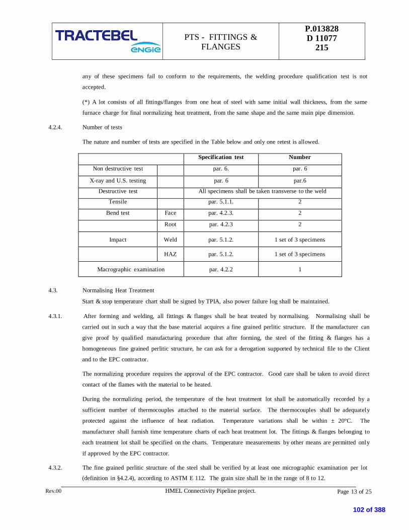
Page 13 of 25
P.013828D 11077
215PTS - FITTINGS &
FLANGES
Rev.00 HMEL Connectivity Pipeline project.
any of these specimens fail to conform to the requirements, the welding procedure qualification test is not
accepted.
(*) A lot consists of all fittings/flanges from one heat of steel with same initial wall thickness, from the same
furnace charge for final normalizing heat treatment, from the same shape and the same main pipe dimension.
4.2.4. Number of tests
The nature and number of tests are specified in the Table below and only one retest is allowed.
Specification test Number
Non destructive test par. 6. par. 6
X-ray and U.S. testing par. 6 par.6
Destructive test All specimens shall be taken transverse to the weld
Tensile par. 5.1.1. 2
Bend test Face par. 4.2.3. 2
Root par. 4.2.3 2
Impact Weld par. 5.1.2. 1 set of 3 specimens
HAZ par. 5.1.2. 1 set of 3 specimens
Macrographic examination par. 4.2.2 1
4.3. Normalising Heat Treatment
Start & stop temperature chart shall be signed by TPIA, also power failure log shall be maintained.
4.3.1. After forming and welding, all fittings & flanges shall be heat treated by normalising. Normalising shall be
carried out in such a way that the base material acquires a fine grained perlitic structure. If the manufacturer can
give proof by qualified manufacturing procedure that after forming, the steel of the fitting & flanges has a
homogeneous fine grained perlitic structure, he can ask for a derogation supported by technical file to the Client
and to the EPC contractor.
The normalizing procedure requires the approval of the EPC contractor. Good care shall be taken to avoid direct
contact of the flames with the material to be heated.
During the normalizing period, the temperature of the heat treatment lot shall be automatically recorded by a
sufficient number of thermocouples attached to the material surface. The thermocouples shall be adequately
protected against the influence of heat radiation. Temperature variations shall be within ± 20°C. The
manufacturer shall furnish time temperature charts of each heat treatment lot. The fittings & flanges belonging to
each treatment lot shall be specified on the charts. Temperature measurements by other means are permitted only
if approved by the EPC contractor.
4.3.2. The fine grained perlitic structure of the steel shall be verified by at least one micrographic examination per lot
(definition in §4.2.4), according to ASTM E 112. The grain size shall be in the range of 8 to 12.
102 of 388

Page 14 of 25
P.013828D 11077
215PTS - FITTINGS &
FLANGES
Rev.00 HMEL Connectivity Pipeline project.
4.3.3. The manufacturer shall include in the CMTR data of this treatment.
5 PHYSICAL TESTING5.1. Mechanical Tests
The following mechanical tests shall be performed by the vendor under the supervision of the TPIA and the
certificates shall be added to the CMTR.
Test specimens may only be cut after a marking transfer by the Authorised TPIA. All the tests shall be performed
after final heat treatment.
Certification requirements to comply with EN 10204 – 3.2 certificates shall issued by TPIA
5.1.1. Tension test
5.1.1.1. Requirements
The material shall be in conformance with the ASTM standards and the ratio of yield stress to tensile stress shall
not exceed 0.90.
For fittings containing welds, the fracture must be outside of the weld. If there is a fracture in weld or HAZ, the
tensile strength shall at least meet the requirements for tensile properties as per ASTM standards.
5.1.1.2. Test specimen
The test specimen shall represent all forgings from the same lot. Test specimens shall be taken from the fitting
after final heat treatment or from a piece of pipe or plate of the same nominal thickness, same heat of steel from
which the fitting is made and which has been heat treated in a lot with any of the fitting(s) it represents. For
welded fittings, this coupon (piece of pipe or plate) shall contain a weld in prolongation of the weld of the fitting.
5.1.1.3. Number of tests
For fittings NPS 2 and greater the following number of test shall be performed:
Base material : one tension test
Weld : one tension test
5.1.1.4. Test locations and orientations
For welds, the test specimen shall be orientated transversally to the weld. For base material, test specimens shall
be orientated transversally and if this orientation is not feasible, it shall be orientated longitudinally.
For flanges, the test location shall be in accordance with ASTM A350§6.1.3.
5.1.1.5. Test method
Testing shall be performed in accordance with ASTM A 370 standard rectangular plate type 1-1/2" wide (Fig. 4-
A370) or standard round (Fig. 5 or Fig. 6-A370). Yield strength shall be determined either by the 0.2 % offset or
the 0.5 % extension under load (EUL) method.
103 of 388

Page 15 of 25
P.013828D 11077
215PTS - FITTINGS &
FLANGES
Rev.00 HMEL Connectivity Pipeline project.
5.1.1.6. Retest
If the tension test specimen from any lot fails to conform to the requirements of the particular grade ordered, the
manufacturer may elect to make retests on two additional pieces from the same lot. If one or both of the retests
fail to conform to the requirements, the whole lot of that specimen will be rejected.
5.1.2. Impact test
5.1.2.1. Requirements
For product, the Charpy V- Notch test shall be conducted as per following requirements:
Material Impact Test Temperature Energy Absorption Value(Minimum)
Carbon Steel Material -20 Deg. C Individual 28J
Average 35J
Low Temperature
Carbon Steel Material
-20 Deg. C Individual 28J
Average 35J
Material Standard’ impact testrequirements temperature or
- 45 Deg. C whichever is lower
Material Standard’s impact testrequirement
5.1.2.2. Test specimen
The test specimen shall be machined from material obtained as in paragraph Test specimen for Tension test (par.
5.1.1.2.).
Flattening of test specimens are not allowed.
5.1.2.3. Number of tests and orientation
Three test specimens shall constitute one test set.
For fittings NPS 2 and greater, the following number of tests shall be performed :
Base material : 2 test sets, one set shall be orientated longitudinally and another one transversally.
Weld : 1 test shall be orientated transversally.
HAZ : 1 test shall be orientated transversally.
5.1.2.4. Test method
The notched bar impact test shall be made in accordance with ISO 148 - Charpy V - Notch.
If the wall thickness of the fitting or the coupon does not enable machining of full size specimens, the largest
possible size must be used but not less than (10 x 5 mm). The axis of the notch shall be orientated through the
wall thickness of the fitting.
5.1.3. Flattening test
104 of 388

Page 16 of 25
P.013828D 11077
215PTS - FITTINGS &
FLANGES
Rev.00 HMEL Connectivity Pipeline project.
This is not applicable to the flanges.
5.1.3.1. Requirements
Flatten to 1/3 original O.D. without cracks or breaks in the fitting, continue flattening until meeting opposite
walls of the fitting.
No evidence of lamination of burnt metal may develop during entire test.
5.1.3.2. Test specimen
The test specimen represents all the fittings from the same heat of steel of the same shape and of the same main
pipe dimension of the fittings.
5.1.3.3. Number of tests
For fittings size lower than 2” one flattening test shall be made per test specimen.
5.1.4. Retreatment
If the result of the mechanical tests does not conform to the requirements specified in par. 5.1.3.1., the
manufacturer, with the acceptance of the Client and the EPC contractor, may reheat treat the fittings as applicable
and repeat all the tests specified.
5.2. Chemical Analysis
For each lot/item a new chemical analysis of the steel shall be done.
The chemical analysis shall conform to the ASTM requirements specified in the specification.
The carbon equivalent shall be computed by "check analysis": see par. 3.10.2 with C.E. 0.43.
The reports shall be added to the CMTR reports and approved by the EPC contractor.
6 NON DESTRUCTIVE EXAMINATIONS (NDE)
The following mechanical tests shall be performed by the vendor under the supervision of the EPC contractor and
the certificates shall be added to the CMTR.
6.1.1. Radiography
All butt and repair welds shall be 100% radiographed in accordance with ASME section V - non destructive
examination - article 2 - using fine grain film and lead screens. Acceptance criteria shall be as be ASME B 31.4
or ASME B 31.8 as applicable and API 1104. Radiography shall be performed after the final heat treatment.
6.1.2. U.S., Magnetic, Visual and Dimensional examination
6.1.2.1. Non destructive examinations
In the presence of the TPIA, the manufacturer shall perform the following non destructive examinations on the
fittings after the mechanical tests and according to an inspection procedure to be submitted for approval.
105 of 388
Page 17 of 25
P.013828D 11077
215PTS - FITTINGS &
FLANGES
Rev.00 HMEL Connectivity Pipeline project.
For fitting with wall thickness larger than or equal to 6 mm, ultrasonic inspection on the whole surface (with
angle probe and straight probe) to the maximum extent possible.
All finished wrought weld ends shall be 100% tested for lamination type defects by ultrasonic test. Any
lamination larger then 6.35 mm shall not be acceptable.
When elbows of size > DN 450 mm (18") are manufactured, the first elbow of each radius, diameter and
wall thickness shall be ultrasonically checked for sufficient wall thickness in areas where a minimum wall
thickness is to be expected. This shall be followed by random inspection of one out of every three elbows of
the same radius, diameter and wall thickness.
Magnetic Particle or Liquid Penetrant Examination shall be performed on cold formed.
Butt welding tees with extruded outlets as per applicable material standard.
Welds, which cannot be inspected by radiographic methods, shall be checked by Ultrasonic or Magnetic
particle methods. Acceptance criteria shall be as per ASME section VIII Appendix U and Appendix VI
respectively.
Magnetic particle inspection on the whole external surface and the accessible internal surface.
6.1.2.2. Ultrasonic inspection
Ultrasonic inspection of all welds and 25 mm of base material at each side of the weld shall be done.
6.1.2.3. Visual examination
All fitting & flanges shall be visually examined.
6.1.2.4. Test after machining
After machining, all the finished bevels shall be submitted to the following tests:
Magnetic particle or liquid penetrant
For fitting and flanges with wall thickness larger than or equal to 6 mm, ultrasonic inspection on 25 mm of
base material.
6.1.2.5. Dimensional examination
For fittings up to NPS 6, the TPIA shall choose 10 % with a minimum of one piece per item of the order and
these pieces shall be submitted to a dimensional examination.
For fittings larger than NPS 6, all pieces shall be submitted to a dimensional examination
All flanges shall be submitted to a dimensional examination.
6.1.3. Acceptance criteria of the different NDE
6.1.3.1. Visual examination
106 of 388
Page 18 of 25
P.013828D 11077
215PTS - FITTINGS &
FLANGES
Rev.00 HMEL Connectivity Pipeline project.
The following defects are unacceptable:
Undercuts exceeding 1 mm in depth and 25 mm in length.
Undercuts of the outside weld which overlap undercuts of the inside weld.
Lack of penetration.
Continuous occurrence of under-cutting.
6.1.3.2. Magnetic particle inspection
Magnetic particle inspection on the external surface. ASME code, section VIII, division 1, appendix VI.
6.1.3.3. Ultrasonic inspection
For the longitudinal welds: ASME code, section VIII, division 1, appendix 12.
For welding ends, see § 6.1.3.5.
For base material :
Procedure: ASME code, section V, art. 23, SA-388.
Criteria: ASME code, section VIII, division 1, UF-55 (angle probe will be used).
6.1.3.4. Radiographic examination
For longitudinal seam welds :
Criteria : ASME code, section VIII, division 1, UW 51
For girth welds :
Criteria: API standards 1104, section 6.0.
6.1.3.5. Magnetic particle or liquid penetrant on the finished bevel
The following defects are unacceptable:
Defects extending into the bevel provided the lamination is parallel to the surface and has a transverse
dimension exceeding 6.35 mm.
All defects not parallel to the surface extending into the bevel.
7 INSPECTION AND TESTING
7.1. Information
The manufacturer shall inform the EPC contractor MIN. 5 working days (15 in case of foreign supplier) in
advance of any intervention required by this specification and shall send a copy (fax) of it to the
Client/Consultant.
107 of 388

Page 19 of 25
P.013828D 11077
215PTS - FITTINGS &
FLANGES
Rev.00 HMEL Connectivity Pipeline project.
Hydrostatic testing by the manufacturer is not required, but welding fittings shall be capable to withstand a field
hydrostatic testing in accordance with par. 2.6.
7.2. Workmanship and Finish
7.3. Fittings & Flanges shall be free of injurious defects and shall have workmanlike finish.
7.4. Injurious defects are defined as those having a depth in excess of 6-1/2 % of specified nominal wall.
7.5. Machining and grinding of surface defects shall be treated as follows: sharp defects such as notches, scratches,
scraps, seams, laps, tears, or slivers not deeper than 6-1/2 % of nominal wall thickness
shall be removed by grinding. Repair of injurious defects by welding shall be permitted only after agreement by
the Client and the EPC contractor, except that welding of injurious defects shall not be permitted when the depth
of defects exceeds 33-1/3 % of the nominal wall thickness, or the length of repair exceeds 25 % of the specified
diameter. Defects must be completely removed and welding performed by a welder qualified specifically for
repair welding, as per par. 4.2.1. Such repair welding shall be ground flush with the surface and all welding shall
be done before final heat treatment. Repair welding shall be done with low hydrogen electrodes in shielded
metal arc welding, gas metal arc process or submerged arc process. In no case, repair welding or cracks nor
repair or repairs is allowed. Repair welding will not be permitted for flanges.
7.6. Repair welding shall be done before the last heat treatment. Adjusting weld preparations, intended for field
welding, by means of welding is not allowed. For "standard fitting" repair by welding is not permitted.
7.7. Repair welding on the welds & in the body shall be 100 % radiographed and U.S tested.
7.8. At the discretion of the TPIA, finished fittings & flanges shall be subject to rejection if surface imperfections
acceptable under cl. no. 7.3 are not scattered but appear over an area in excess of what is considered as a
workmanlike finish.
7.9. Rejection
Each fitting or flange in which injurious defects are found during inspection and after delivery shall be rejected.
The manufacturer shall be notified. In this case, the fitting shall be replaced immediately. All the costs involved,
including wages and travel expenses of the EPC contractor/Client/ Consultant shall be borne by the
manufacturer.
8 MARKING
8.1.1. All fittings and flanges furnished under this specification shall be clearly identified on the O.D. with the
following information marked with low stress die stamps or interrupted dot stamps as noted (refer to MS SP25):
Manufacturer's name or trademark.
Heat code identity.
108 of 388

Page 20 of 25
P.013828D 11077
215PTS - FITTINGS &
FLANGES
Rev.00 HMEL Connectivity Pipeline project.
Fitting or flange number: the fitting or flange number shall be made up of six figures specified as follows:
the item and his number specified in the purchase order.
The monogram of the EPC contractor. This marking shall only be applied after complete approval of the
Certified Material Test Report (see par. 9.2.).
8.1.2. In addition to the above, for NPS 2" and larger, it shall also include the following information:
Grade symbol: the grade symbol must designate the material of the fitting or flange.
8.1.3. Marking must be done prior to final inspection.
9 DOCUMENTATION
9.1. Before starting any control, the manufacturer shall submit for approval to the EPC contractor and the
Client/Consultant the following documents:
Detailed fabrication drawing and calculations.
Fabrication and control procedure (if new -not if upgraded).
List of Operations of Control (LOC) in accordance with PTS(if new -not if upgraded).
Material list.
Qualified welding procedures (if new -not if upgraded).
Welder’s performances qualifications (if new -not if upgraded).
Heat treatment procedure-(if new -not if upgraded).
Non destructive testing procedures.
Each company dealing in the order by fabrication and/or control shall implement a LOC for all operations and
interventions performed in its organization. They shall also be responsible for the implementation of the same by
their subcontractors.
9.2. Certified Material Test Report
A Certified Material Test Report (CMTR) shall be furnished listing as built drawing and calculations, the LOC
(see paragraph 9.1.), the proof test certificate, the base material certificate, the chemical check analysis. The
certificate of the heat treatment, the mechanical tests, the non-destructive examination, the mechanical properties,
the quality release note (see paragraph 9.3) and any special test required by the purchase order the fitting or
flange individual number (see paragraph 8.1.1.) must be indicated in the CMTR to permit the correct traceability
of each piece. The manufacturer shall furnish one copy of the CMTR to the EPC contractor and one original and
one copy to the Client/Engineer.
9.3. IRN
109 of 388

P.013828D 11077
215PTS - FITTINGS &
FLANGES
Rev.00 Page 21 of 25HMEL Connectivity Pipeline Project.
After final approval of fittings/flanges and the acceptance of the CMTR, the EPC contractor shall furnish to the
Client/Consultant and to the manufacturer an Inspection Release Note (IRN). The manufacturer shall deliver one
copy of the IRN with the fittings/flanges and one copy shall be included in the CMTR (see paragraph 9.2.).
10 CORROSION PROTECTION
The corrosion protection will be applied by the manufacturer after final inspection by the EPC contractor.
The product shall meet the following criteria:
Guarantee a corrosion protection for a storage period in open air for at least6 months.
Shall be easily removable by wire brushing or bygrinding.
It shall not produce toxic vapour or smoke when heated by blow torches or duringwelding.
110 of 388

P.013828D 11077
215PTS - FITTINGS &
FLANGES
Rev.00 Page 22 of 25HMEL Connectivity Pipeline Project.
TABLE 1
CHEMICAL COMPOSITION FOR FITTINGS
Maximum limit of chemical elements which may be used in material under this standard.
% MAXIMUM
C 0.230
Mn 1.60
Si 0.50
P 0.030
S 0.025
Nb 0.080
V 0.120
Mo 0.250
Nt 0.0150
Alternate alloy elements may be used but they shall be discussed with the user prior to delivery of the material. This table is
not intended to represent the composition of any heat of steel, but merely to record the maximum permissible amounts of one
element. The combination of elements of any heat must conform to the carbon equivalent, subsection 3.10.2.
For each heat the manufacturer shall analyse the following elements:
C, Mn, Si, P, S, Nb, V, Cr, Mo, Ni and Cu.
The intentional addition of elements other than those specified is not permitted unless agreed upon by the Client.
In any case, for unintentional additions, the following limitations shall be respected :
Cr 0.15 % Mo 0.05 % Cu 0.20 %
Ni 0.30 % Co 0.01 % Al 0.07 %
The content of N total (Nt) may be up to 0.0150 % and must be guaranteed by the manufacturer. If the manufacturer cannot
give any guaranty of N content, he shall analyse this element.
The total content for Nb + V will be limited to 0.150 %.
For each reduction of 0.01 % below the maximum carbon content, an increase of 0.05 % manganese above the specified
maximum is permissible, up to a maximum of 1.70 %.
111 of 388
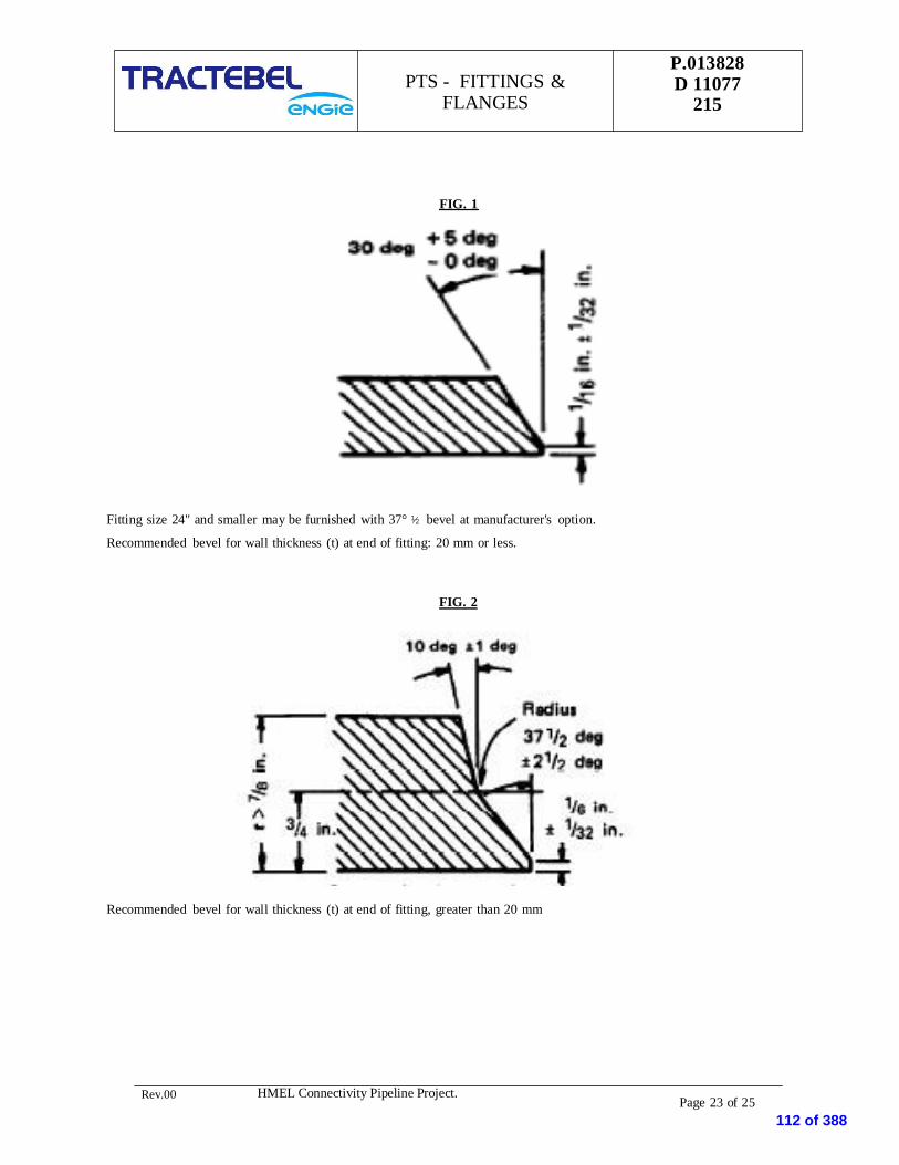
P.013828D 11077
215PTS - FITTINGS &
FLANGES
Rev.00 Page 23 of 25HMEL Connectivity Pipeline Project.
FIG. 1
Fitting size 24" and smaller may be furnished with 37° ½ bevel at manufacturer's option.
Recommended bevel for wall thickness (t) at end of fitting: 20 mm or less.
FIG. 2
Recommended bevel for wall thickness (t) at end of fitting, greater than 20 mm
112 of 388

P.013828D 11077
215PTS - FITTINGS &
FLANGES
Rev.00 HMEL Connectivity Pipeline Project. Page 23 of 25
FIG. 3
TRANSVERSE FACE AND ROOT BEND TEST SPECIMENS
113 of 388

Rev.00 HMEL Connectivity Pipeline Project. Page 24 of 25
P.013828D 11077
215
PTS - FITTINGS &FLANGES
FIG 5
GUIDED-BEND TEST JIG DIMENSIONS
Radius of male member R ARadius of female member R BWidth of male member, A
Width of groove in female member, B
CLASS OF STEEL
Y52 and low-grade Y56 Y60 Y70
½ A
½ B
4 t
A + 2t + 3.2 mm
½ A
½ B
5 t
A + 2t + 3.2 mm
½ A
½ B
6 t
A + 2t + 3.2 mm
½ A
½ B
8 t
A + 2t + 3.2 mm
t = specimen thickness
The manufacturer shall use a jig based on this dimension, or a smaller dimension at his option.
114 of 388

Rev.00 HMEL Connectivity Pipeline Project. Page 25 of 25
P.013828D 11077
215
PTS - FITTINGS &FLANGES
FIG. 6
SPECTACLE FLANGE
115 of 388

PIPING SPECIFICATION
6C1DOC. NO :
P.013828 D 11077 217SHEET 1 OF 6
ASME B 31.8 Carbon Steel - 20 to 65 Carbon Steel 98.00600#-RF LTCS - 45 to 65 LTCS 98.00
(BARE PIPE - TO BEPAINTED AT SITE)
LTCS (See Note 3)
CARBON STEEL Temperature(Deg.C)
Pressure bar (g)
° C bar (g)
CORROSION ALLOWANCE -29 102.04
CARBON STEEL 2.0 mm 0 102.04
2.0 mm 38 102.04
100% 65 98.00
PIPE SIZE RANGE 1/2"- 12"
00 13.04.2019 MS NC SKHREV DATE PREAPARED CHECKED APPROVED
FILTRATION, METERING & PRS SKID For HMELConnectivity Pipeline Project
PRESSURE bar(g)
FLUIDS
1/2" to 10"
12"
NG : NATURAL GAS
DESCRIPTIONIssued for RFP
2. ALL ABOVE GROUND (A/G) STATION PIPES SHALL BE BARE PIPES. THE PIPES SHALL BE PAINTED AT SITE, AS PER PROJECTSPECIFICATIONS FOR PAINTING OF ABOVE GROUND STATION PIPING.
BASIC PIPING SPECIFICATION DATASTEMPERATURE °C
6 C1 - PMS for PIPELINE AND STATION Piping
Temperature & Pressure Rating
LTCS
DESIGN CODE
MAXIMUM PIPELINE DESIGN CONDITIONS
3. MATERIAL FOR 1/2" TO 10" STATION PIPING SHALL BE ASTM A 333, GRADE 6 (LTCS). LTCS MATERIAL SHALL BE CHARPYIMPACT TESTED AT (-45 °C).
X-RAYS
BASIC MATERIAL
PRIMARY FLANGE RATING
Note :1. '6C1' INDICATES - 600# PIPING AND PIPELINE
AG : ACTUATING GAS
Laying and Associated Works For HMEL Connectivity Pipeline Project 116 of 388

PIPING SPECIFICATION
6C1DOC. NO :
P.013828 D 11077 217SHEET 2 OF 6
REV. 00ITEM SHORT SIZE END RATING DIMENSION MATERIAL REMARKS
CODE FROM- CONNECTION AND/OR STANDARD
THRU SCH/THK
PIPES P 1/2" - 1 1/2" PE-ANSI B16-25 160 ANSI B 36-10 ASTM A333 GR 6 SEAMLESS (LTCS)
PIPES P 2" BE-ANSI B16-25 160 ANSI B 36-10 ASTM A333 GR 6 SEAMLESS (LTCS)
PIPES P 3" - 10" BE-ANSI B16-25 80 ANSI B 36-10 ASTM A333 GR 6 SEAMLESS (LTCS)
PIPES P 12'' BE-ANSI B16-25 7.1 mm Thk API 5L API5L X 70 12" - CLASS 1
PIPES P 12'' BE-ANSI B16-25 7.1 mm Thk API 5L API5L X 70 12" - CLASS 2
PIPES P 12'' BE-ANSI B16-25 8.7 mm Thk API 5L API5L X 70 12" - CLASS 3
PIPES P 12'' BE-ANSI B16-25 9.5 mm Thk API 5L API5L X 70 12" - CLASS 4
PIPES P 12'' BE-ANSI B16-25 8.7 mm Thk API 5L API5L X 70 STATION PIPING.
PIPES P 12'' BE-ANSI B16-25 9.5 mm Thk API 5L API5L X 70 12" HOT INDUCTION BENDS AT STATIONS (CLASS 4 THICKNESS)
ELBOWS 90 LR E 1/2"- 1 1/2" BW - ANSI B16-25 SEE PIPE & note 1 ANSI B16-9 ASTM A 350 LF2, CL1 SMLS
ELBOWS 90 LR E 2"- 10" BW - ANSI B16-25 SEE PIPE & note 1 ANSI B16-9 ASTM A420 WPL 6 SMLS
ELBOWS 90 LR E 12'' BW - ANSI B16-25 SEE PIPE & note 1 ANSI B16-9 API5L X70 or A860 WPHY 70
ELBOWS 45 LR note 1 E45 1/2"- 1 1/2" BW - ANSI B16-25 SEE PIPE & note 1 ANSI B16-9 ASTM A 350 LF2, CL1 SMLS
ELBOWS 45 LR note 1 E45 2"- 10" BW - ANSI B16-25 SEE PIPE & note 1 ANSI B16-9 ASTM A420 WPL 6 SMLS
ELBOWS 45 LR note 1 E45 12'' BW - ANSI B16-25 SEE PIPE & note 1 ANSI B16-9 API5L X70 or A860 WPHY 70
REDUCERS CONC RC 1/2"- 1 1/2" BW - ANSI B16-25 SEE PIPE & note 1 ANSI B16-9 ASTM A 350 LF2, CL1 SMLS
REDUCERS CONC RC 2"- 10" BW - ANSI B16-25 SEE PIPE & note 1 ANSI B16-9 ASTM A420 WPL 6 SMLS
REDUCERS CONC RC 12'' BW - ANSI B16-25 SEE PIPE & note 1 ANSI B16-9 API5L X70 or A860 WPHY 70
REDUCERS ECC RE 1/2"- 1 1/2" BW - ANSI B16-25 SEE PIPE & note 1 ANSI B16-9 ASTM A 350 LF2, CL1 SMLS
REDUCERS ECC RE 2"- 10" BW - ANSI B16-25 SEE PIPE & note 1 ANSI B16-9 ASTM A420 WPL 6 SMLS
REDUCERS ECC RE 12'' BW - ANSI B16-25 SEE PIPE & note 1 ANSI B16-9 API5L X70 or A860 WPHY 70
TEES EQUAL T 1/2"- 1 1/2" BW - ANSI B16-25 SEE PIPE & note 1 ANSI B16-9 ASTM A 350 LF2, CL1 SMLS
TEES EQUAL T 2"- 10" BW - ANSI B16-25 SEE PIPE & note 1 ANSI B16-9 ASTM A420 WPL 6 SMLS
TEES EQUAL T 12'' BW - ANSI B16-25 SEE PIPE & note 1 ANSI B16-9 API5L X70 or A860 WPHY 70
TEES RED Note 13
(See Note 1) TR
3"- 10"(Mainline Size) BW - ANSI B16-25 SEE PIPE & note 1 ANSI B16-9 ASTM A420 WPL 6
SMLSThe size inicated in this table refers to Mainline sizeof Tee Connection. For Branch Size, Please refer to
the Chart given in Sheet 6 of this Document.
TEES RED Note 13
(See Note 1)
12''(Mainline Size)
BW - ANSI B16-25 SEE PIPE & note 1 ANSI B16-9 API5L X70 or A860 WPHY 70
SMLSThe size inicated in this table refers to Mainline sizeof Tee Connection. For Branch Size, Please refer to
the Chart given in Sheet 6 of this Document.
BARRED TEE EQUAL(See Note 1) T2 12'' BW - ANSI B16-25 SEE PIPE & note 1 ANSI B16-9 API5L X70 or A860 WPHY 70 SMLS
BARRED TEE RED(See Note 1) TR2
12''(Mainline Size) BW - ANSI B16-25 SEE PIPE & note 1 ANSI B16-9 API5L X70 or A860 WPHY 70
The size inicated in this table refers to Mainline sizeof Tee Connection. For Branch Size, Please refer tothe Chart given in Sheet 6 of this Document.
WELDOLETS WEL1 1/2"-10''
(Mainline Size)BW - ANSI B16-25 SEE PIPE & note 1 MSS-SP-97 ASTM A 350 LF2, CL1
The size inicated in this table refers to Mainline size.For Branch Size of Weldolet, Please refer to the
Chart given in Sheet 6 of this Document
WELDOLETS WEL12''
(Mainline Size)BW - ANSI B16-25 SEE PIPE & note 1 MSS-SP-97 ASTM A 350 LF2, CL1
The size inicated in this table refers to Mainline size.For Branch Size of Weldolet, Please refer to the
Chart given in Sheet 6 of this DocumentCAPS C 1/2"- 10" BW - ANSI B16-25 SEE PIPE & note 1 ANSI B16-9 ASTM A420 WPL 6
CAPS C 12'' BW - ANSI B16-25 SEE PIPE & note 1 ANSI B16-9 API5L X70 or A860 WPHY 70
NIPPLES NBEP 1/2" - 1 1/2" BOTH ENDS PLAIN 160 ANSI B36-10 ASTM A333 GR 6 SEAMLESS-LG=100mm
NIPPLES NOET 1/2" - 1 1/2" ONE END THRD-MNPT 160 ANSI B36-10 ASTM A333 GR 6 SEAMLESS-LG=100mm
NIPPLES NBET 1/2" - 1 1/2" BOTH ENDS THRD-MNPT
160 ANSI B36-10 ASTM A333 GR 6 SEAMLESS-LG=100mm
FULL COUPLINGS CF 1/2" - 1 1/2" FNPT 3000# ANSI B16-11 ASTM A 350 LF2, CL1 THREADED
FULL COUPLINGS CF ANSI B1-20-2
CAPS C2 1/2" - 1 1/2" FNPT 3000# ANSI B16-11 ASTM A 350 LF2, CL1
THRD C2 ANSI B1-20-1
PLUGS PL 1/2" - 1 1/2" MNPT 3000# ANSI B16-11 ASTM A 350 LF2, CL1
THRD ANSI B1-20-1
FILTRATION, METERING & PRS SKID For HMELConnectivity Pipeline Project
6 C1 - PMS for Piping
NOTE 1 :WALL THICKNESS FOR TEES, ELBOWS, REDUCERS AND CAPS SHALL BE DETERMINED BY VENDOR AS PER THE REQUIREMENTS OF ASME B 16.9 § 2.3. MINIMUM THICKNESS OFTEE SHALL ALSO MEET THE REQUIREMENTS OF ASME B 31.8, APPENDIX -F FOR BRANCH OPENING. FURTHER, MINIMUM THICKNESS OF TEES, ELBOWS, REDUCERS AND CAPSSHALL NOT BE LESS THAN THAT OF MATING PIPE. ALL WALL THICKNESS CALCULATIONS SHALL BE APPROVED BY OWNER. THE MATING PIPE DETAILS SHALL BE TAKEN ASMENTIONED IN THE PIPE SECTION OF THIS PMS.
Laying and Associated Works For HMEL Connectivity Pipeline Project 117 of 388

PIPING SPECIFICATION
6C1DOC. NO :
P.013828 D 11077 217SHEET 3 OF 6
REV. 00ITEM SHORT SIZE END RATING DIMENSION MATERIAL REMARKS
CODE FROM- CONNECTION AND/OR STANDARD
THRU SCHED.WN FLANGESnote 2
F 1/2"- 2" BW - ANSI B16-25 600# WNRF, SCH 160 ANSI B16-5 ASTM A350 LF2, CL1 Note 2
WN FLANGESnote 2
F 3"- 10" BW - ANSI B16-25 600# WNRF, SCH 80 ANSI B16-5 ASTM A350 LF2, CL1 Note 2
WN FLANGESnote 2
F 12'' BW - ANSI B16-25 600# WNRF, SEE PIPE ANSI B16-5 ASTM A694 F70 OR EQUIVALENT Note 2
ORIFICE FO 1" - 10" For 600 # WNRF ANSI B16-36 ASTM A350 LF2, CL1
ORIFICE FO 12'' For 600 # WNRF ANSI B16-36 ASTM A694 F70 OR EQUIVALENT
BLIND FB 1/2"- 10" For 600 # WNRF ANSI B16-5 ASTM A350 LF2, CL1
BLIND FB 12'' For 600 # WNRF ANSI B16-5 ASTM A694 F70 OR EQUIVALENT
SPECTACLE SB 1" - 10" For 600 # WNRF ANSI B16.48 ASTM A350 LF2, CL1
SPECTACLE SB 12'' For 600 # WNRF ANSI B16.48 ASTM A694 F70RESTRICTION
ORIFICE RO 1" - 10" For 600 # WNRF ANSI B16-5 ASTM A240 GR 304
RESTRICTIONORIFICE
RO 12'' For 600 # WNRF ANSI B16-5 ASTM A694 F70
MONOLITHICINSULATIONJOINT
IJ 2"-10" BW - ANSI B16-25 600# MANUF STD. ASTM A350 LF2 CL1,or A420 WPL 6 Note 2
MONOLITHICINSULATIONJOINT
IJ 12'' BW - ANSI B16-25 600# MANUF STD. ASTM A694 F70 Note 2
STUD BOLTS B All Sizes For 600 # WNRFASME B 18.2.1 &
ASME B 18.2.2STUD BOLTS: ASTM A320 GR. L7,HEXAGONAL NUTS : ASTM A194
GR 4GASKETS
SPIRALWOUND
G All Sizes For 600 # WNRF ASME B 16.20WINDING AISI 304, FILLING PUREGRAPHITE. CENTERING RING CS 4.5 mm THK
NOTE 2 :BORE OF FLANGE SHALL MATCH INSIDE DIA OF MATING PIPE. THE MATING PIPE DETAILS SHALL BE TAKEN AS MENTIONED IN THE PIPE SECTION OF THIS PMS.
FILTRATION, METERING & PRS SKID For HMELConnectivity Pipeline Project
6 C1 - PMS for Piping
Laying and Associated Works For HMEL Connectivity Pipeline Project 118 of 388

PIPING SPECIFICATION
6C1DOC. NO :
P.013828 D 11077 217SHEET 4 OF 6
REV. 00
ITEM SHORT SIZE END RATING DIMENSION MATERIAL REMARKS
CODE FROM- CONNECTION AND/OR STANDARD
THRU SCHED.
BALL VALVES(See Note 3) VBA 1/2" - 1 1/2" FLGD RF:ANSI B16-5 600# ANSI B16-10
BODY : ASTM A350 LF2, CL1 /ASTM A 352 Gr. LCBBALL : ASTM A 182 Gr. F316 ORASTM A 351 GR. CF8M OR(ASTM A350 LF2, CL1 / ASTM A352 Gr. LCC) + ENP
FULL BOREFIRE SAFEWRENCH OPERATED.
BALL VALVES(See Note 3) VBA 2" - 4" FLGD RF:ANSI B16-5
or BW: ANSI B16-25 600# ANSI B16-10
BODY : ASTM A350 LF2, CL1 /ASTM A 352 Gr. LCBBALL : ASTM A 182 Gr. F316 ORASTM A 351 GR. CF8M OR(ASTM A350 LF2, CL1 / ASTM A352 Gr. LCC) + ENP
DOUBLE BLOCK AND BLEEDFULL BOREFIRE SAFEWRENCH OPERATED
BALL VALVES(See Note 3) VBA 6"- 12'' FLGD RF:ANSI B16-5
or BW: ANSI B16-25 600# ANSI B16-10
BODY : ASTM A350 LF2, CL1 /ASTM A 352 Gr. LCBBALL : ASTM A 182 Gr. F316 ORASTM A 351 GR. CF8M OR(ASTM A350 LF2, CL1 / ASTM A352 Gr. LCC) + ENP
DOUBLE BLOCK AND BLEEDFULL BOREFIRE SAFEGEAR OPERATED :MANUAL / ACTUATED - ASINDICATED IN DATA SHEET
GLOBE VALVES
VGL 1/2"-1 1/2" FLGD RF:ANSI B16-5 600# ANSI B16-10
BODY : ASTM A350 LF2, CL1 /ASTM A 352 Gr. LCCDISC / RING : (ASTM A350 LF2,CL1 / ASTM A 352 Gr. LCC) + 13%CR. STEEL FACINGSTEM : 13% CR. STEEL (NOCASTING)
HANDWHEEL FIRE SAFE
VGL 2" - 4" FLGD RF:ANSI B16-5 600# ANSI B16-10
BODY : ASTM A350 LF2, CL1 /ASTM A 352 Gr. LCCDISC / RING : (ASTM A350 LF2,CL1 / ASTM A 352 Gr. LCC) + 13%CR. STEEL FACINGSTEM : 13% CR. STEEL (NOCASTING)
HANDWHEEL FIRE SAFE
VGL 6" - 12" FLGD RF:ANSI B16-5 600# ANSI B16-10
BODY : ASTM A350 LF2, CL1 /ASTM A 352 Gr. LCCDISC / RING : (ASTM A350 LF2,CL1 / ASTM A 352 Gr. LCC) + 13%CR. STEEL FACINGSTEM : 13% CR. STEEL (NOCASTING)
GEAR OPERATED FIRE SAFE
SWING CHECK
VCH 2"- 12'' FLGD RF:ANSI B16-5 600# ANSI B16-10
BODY : ASTM A350 LF2, CL1 /ASTM A 352 Gr. LCCHINGE PIN : 13% CR. STEEL (NOCASTING)DISC / RING : ASTM A350 LF2,CL1 / ASTM A 352 Gr. LCC)+ 13% CR. STEEL FACING
HORIZONTAL INSTALLATIONVERTICAL INSTALLATION FLOWUPWARDS
NOTE 3 :PUP PIECES SHALL BE PROVIDED FOR BUTT WELDED VALVES AS PER THE DATASHEET. MINIMUM THICKNESS OF PUP PIPECE SHALL BE DETERMINEDBY VENDOR AS PER THE REQUIREMENTS OF ASME B 31.8, FIG I-5 FOR WELDING TO VALVE DESIGNED AS PER ASME B 16.34. THE THICKNESSCALCULATIONS SHALL BE APPROVED BY CLIENT. THE PIPE END OF THE PUP PIECE SHALL MATCH THE THE MATING PIPE.THE MATING PIPE DETAILSSHALL BE TAKEN AS MENTIONED IN THE PIPE SECTION OF THIS PMS.
FILTRATION, METERING & PRS SKID For HMELConnectivity Pipeline Project
6 C1 - PMS for Piping
Laying and Associated Works For HMEL Connectivity Pipeline Project 119 of 388
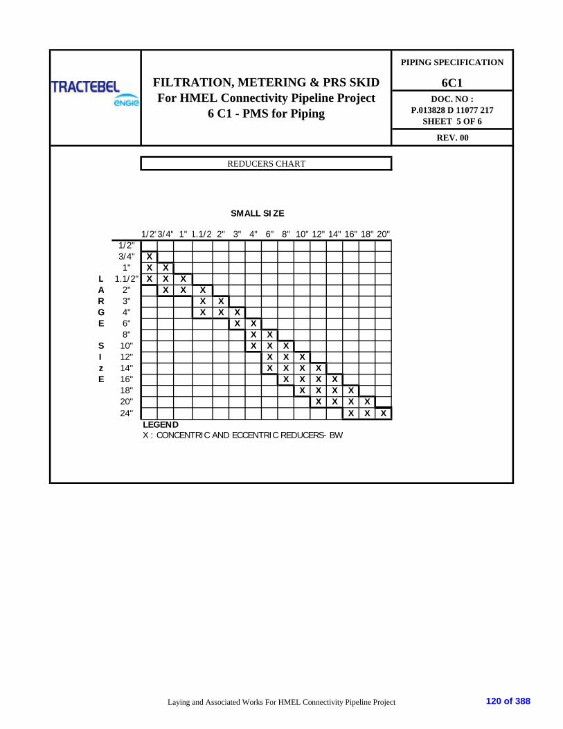
PIPING SPECIFICATION
6C1DOC. NO :
P.013828 D 11077 217SHEET 5 OF 6
REV. 00
SMALL SIZE
1/2"3/4" 1" 1.1/2" 2" 3" 4" 6" 8" 10" 12" 14" 16" 18" 20"1/2"3/4" X1" X X
L 1.1/2" X X XA 2" X X XR 3" X XG 4" X X XE 6" X X
8" X XS 10" X X XI 12" X X Xz 14" X X X XE 16" X X X X
18" X X X X20" X X X X24" X X X
LEGENDX : CONCENTRIC AND ECCENTRIC REDUCERS- BW
REDUCERS CHART
FILTRATION, METERING & PRS SKIDFor HMEL Connectivity Pipeline Project
6 C1 - PMS for Piping
Laying and Associated Works For HMEL Connectivity Pipeline Project 120 of 388
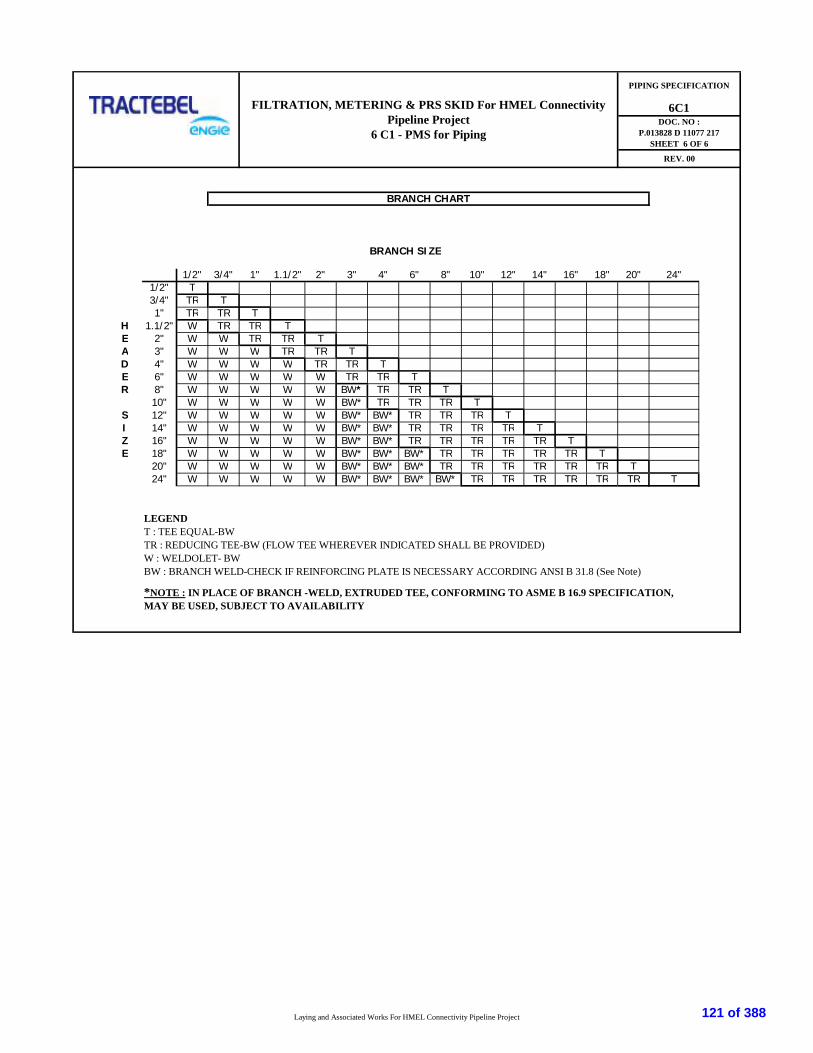
BRANCH SIZE
1/2" 3/4" 1" 1.1/2" 2" 3" 4" 6" 8" 10" 12" 14" 16" 18" 20" 24"1/2" T3/4" TR T1" TR TR T
H 1.1/2" W TR TR TE 2" W W TR TR TA 3" W W W TR TR TD 4" W W W W TR TR TE 6" W W W W W TR TR TR 8" W W W W W BW* TR TR T
10" W W W W W BW* TR TR TR TS 12" W W W W W BW* BW* TR TR TR TI 14" W W W W W BW* BW* TR TR TR TR TZ 16" W W W W W BW* BW* TR TR TR TR TR TE 18" W W W W W BW* BW* BW* TR TR TR TR TR T
20" W W W W W BW* BW* BW* TR TR TR TR TR TR T24" W W W W W BW* BW* BW* BW* TR TR TR TR TR TR T
LEGENDT : TEE EQUAL-BWTR : REDUCING TEE-BW (FLOW TEE WHEREVER INDICATED SHALL BE PROVIDED)W : WELDOLET- BWBW : BRANCH WELD-CHECK IF REINFORCING PLATE IS NECESSARY ACCORDING ANSI B 31.8 (See Note)
6C1DOC. NO :
P.013828 D 11077 217SHEET 6 OF 6
REV. 00
BRANCH CHART
*NOTE : IN PLACE OF BRANCH -WELD, EXTRUDED TEE, CONFORMING TO ASME B 16.9 SPECIFICATION,MAY BE USED, SUBJECT TO AVAILABILITY
FILTRATION, METERING & PRS SKID For HMEL ConnectivityPipeline Project
6 C1 - PMS for Piping
PIPING SPECIFICATION
Laying and Associated Works For HMEL Connectivity Pipeline Project 121 of 388

PTS - PAINTING P.013828
D 11077
218
HMEL CONNECTIVITY PIPELINE PROJECT.
TRACTEBEL ENGINEERING PVT. LTD.
PTS - PAINTING
00 16.04.02019 Issued for RFP MK MS AR
Rev. Date Subject of Revision Prepared By Checked By Approved By
122 of 388

PTS - PAINTING P.013828
D 11077
218
Rev. 00 HMEL Connectivity Pipeline Project. Page 1 of 1
TABLE OF CONTENTS
1.0 INTRODUCTION ................................................................................................................... 1
2.0 DEFINITIONS ....................................................................................................................... 1
3.0 COLOUR CODE SYSTEM ........................................................................................................ 1
123 of 388
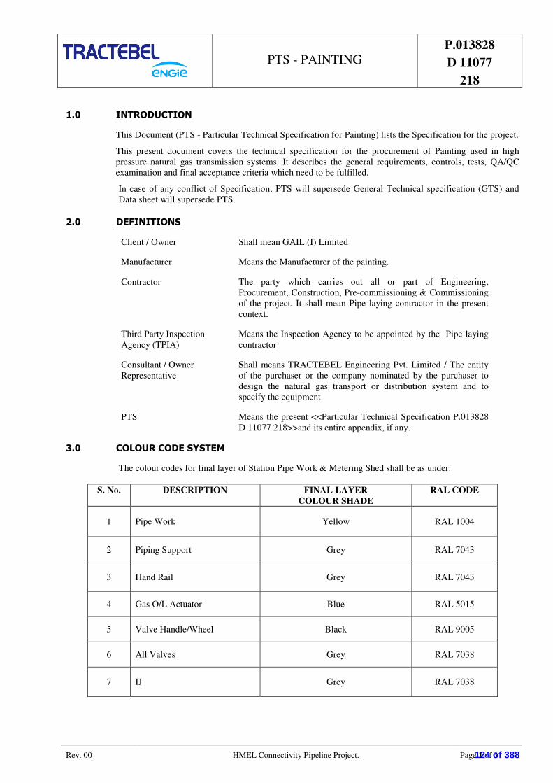
PTS - PAINTING P.013828
D 11077
218
Rev. 00 HMEL Connectivity Pipeline Project. Page 1 of 3
1.0 INTRODUCTION
This Document (PTS - Particular Technical Specification for Painting) lists the Specification for the project.
This present document covers the technical specification for the procurement of Painting used in high
pressure natural gas transmission systems. It describes the general requirements, controls, tests, QA/QC
examination and final acceptance criteria which need to be fulfilled.
In case of any conflict of Specification, PTS will supersede General Technical specification (GTS) and
Data sheet will supersede PTS.
2.0 DEFINITIONS
Client / Owner Shall mean GAIL (I) Limited
Manufacturer Means the Manufacturer of the painting.
Contractor The party which carries out all or part of Engineering,
Procurement, Construction, Pre-commissioning & Commissioning
of the project. It shall mean Pipe laying contractor in the present
context.
Third Party Inspection
Agency (TPIA)
Means the Inspection Agency to be appointed by the Pipe laying
contractor
Consultant / Owner
Representative
Shall means TRACTEBEL Engineering Pvt. Limited / The entity
of the purchaser or the company nominated by the purchaser to
design the natural gas transport or distribution system and to
specify the equipment
PTS Means the present <<Particular Technical Specification P.013828
D 11077 218>>and its entire appendix, if any.
3.0 COLOUR CODE SYSTEM
The colour codes for final layer of Station Pipe Work & Metering Shed shall be as under:
S. No. DESCRIPTION FINAL LAYER
COLOUR SHADE
RAL CODE
1 Pipe Work Yellow RAL 1004
2 Piping Support Grey RAL 7043
3 Hand Rail Grey RAL 7043
4 Gas O/L Actuator Blue RAL 5015
5 Valve Handle/Wheel Black RAL 9005
6 All Valves Grey RAL 7038
7 IJ Grey RAL 7038
124 of 388

PTS - PAINTING P.013828
D 11077
218
Rev. 00 HMEL Connectivity Pipeline Project. Page 2 of 3
8 Filter Grey RAL 7038
9 Pig launcher & Receiver Grey RAL 7038
10 Bolts & Nuts Grey RAL 7038
11 Grating Hot Galvanized
12 Metering Station Shed
12.1 Steel Frame Beige RAL 1018
12.2 Roof / Vertical Shed Grey RAL 7030
12.3 Control Panel Grey RAL 7032
The recommended painting system should be of Category C5 – I Very high (Industrial) as specified in the Standard ISO
12944 Part 1 to 8. The proposed Painting system shall conform to Table A5 of ISO 12944 – 5 Standard.
125 of 388

PTS - PAINTING P.013828
D 11077
218
Rev. 00 HMEL Connectivity Pipeline Project. Page 3 of 3
∑ ∑ ∑
126 of 388

1 GENERAL
1.1 Tag No. As per P & I diagram
1.2 Service Natural Gas
1.3 Line No. As per P & I diagram
1.4 P&ID No. P.013828-D-21097-100 ,P.013828-D-21097-401,P.013828-D-21097-402,P.013828-D-21097-403
1.5 Location
1.6 Quantity
1.7 Reference Drg. No. -
2 OPERATING CONDITIONS
2.1 Fluid / State Natural Gas /Gaseous
2.2 FLOW Capacity (MMSCMD)
2.3 Design Pressure Kg/cm2
2.4 Design Temp. (Degree Celsius)
2.6 SP. Gravity / MOL / WT> Refer Note 1
2.7 Vapor Press / Critical Press Vendor to furnish
2.8 Pressure Drop (Max. Allowable) For Dirty Gas Pressure Drop Shall be 0.5 Barg
For Clean Gas Pressure Drop Shall be 0.25 Barg
2.9 Gas Operating Temperature Vendor to furnish
2.10 Suspended Solids
2.11 Filtration efficiency 99.9%, Removing liquid and solid particle of size >5 micron
3 DESING / CONSTRUCTION DATA
3.1 filter make / model Vendor to furnish
3.2 Type of Filter Coalescing Dry Gas
3.3 Number of elements Vendor to furnish
3.4 Design Code / Standards ASME VIII DIV I Code stamp (U-stamp is required)
- Piping Welding Code ASME Sec IX
- NDE Code ASME B 31.3, ASME Sec V
3.5 Size of Vessel
- Shell dia Vendor to furnish
- Length Vendor to furnish
- Height Total Vendor to furnish
- Type of Dish end 2:1
- Top cover With Quick opening closure
- Lifting lugs Yes, to be Provided
3.6 Material of Construction
- Shell SA - 516 Gr. 70
- Heads SA - 516 Gr. 70
- Filter element Fiber glass
- Filter element holder (van box) SS-304
- Top cover ring (Pressure and Segment) SA 350 LF2
- Name Plate SS 304
- Filter frame SA - 516 Gr. 70
Supports (Skirts) SA - 516 Gr. 70
Flanges (shell + nozzle + cover) ASTM - A 350 LF2
- Rating ANSI 16.5, 600#
- Gasket Spiral Bound SS 316 + PTFE Filled
Nozzle Necks SA 333 Gr. 6 (Seamless Pipe)
Internal fittings SS 304 / 316
Bolts / nuts / Washer SA 320 Gr. 7 / SA - 194 Gr. 7
Structural attachments
Internal SA 516 Gr. 70
External SA 516 Gr. 70
Insulation NIL
Vent pipe SA 333 Gr. 6
Base plate IS:2062 Gr. A
Cover flanges (QOC) SA-350 LF2
CLIENT:
PROJECT: 00 MK MS SKH
Rev. ATHR CHKD APPD
GAIL INDIA LTD. LIMITED
Filtration, Metering & Pressure ReductionSkids for HMEL Connectivity Pipeline
Project.
DATA SHEETCOALESCING DRY GAS FILTER
DATA SHEET No.
P.013828 D11088 219
Page 1 of 2
Date
16.04.2019
UNITS: Flow <_> Liquid - m*3/hr Gas-Sm*3/hr Steam - kg/hr Pressure - > kg/cm*2 G Temperature <_> oC Level/Length <_> mm
GAIL INDIA LTD.
Filtration, Metering & Pressure Reduction Skids forHMEL Pipeline Connectivity Project.
1 (One) Nos.
RECEIVING TERMINAL AT HMEL
Minimum Normal Maximum
53.00 53-65
Design
15 25 40 -29 to 65
0.2 0.2-1.0 1.2 1.2
95 99.9
Filteration, Metering Pressure Reduction Skids for HMEL Pipeline Connectivity Project.
127 of 388

3.7 Add in Design Data
- Joint efficiency 1
PWHT YES
Radiography
Hydro test Pressure 1.5 X Design Pressure
Corrosion Allowance 3 mm
Impact Test
3.8 Total Erection weight of filter assembly Refer Note 1
3.9 Painting
4 ACCESSORIES & INSTRUMENTATION4.1 A relief valve on shell side with isolating block valve4.2 A level gauge on liquid chamber4.3 A level transmitter on liquid chamber
- Local level indicator Manufacturer / Model- With high level alarm Size / Flanges Rating- With outgoing signals to SCADA Type / Make / Model
4.4 A level gauge on dust chamber Connection Size / Rating4.5 A level transmitter on dust chamber Type / Make / Model
- Local level indicator Connection Size / Rating- With high level alarm Type / Make / Model- With outgoing signals to SCADA Connection Size / Rating
4.6 A pressure drop transmitter Connection Size / Rating- Local level indicator Type / Connections- With high level alarm Make / Model- With outgoing signals to SCADA Type / Connections
4.7 Manual vent valves Make / Model4.8 Manual drain valves4.9 Relief valves Type Refer Note 1
Size / flange Rating Refer Note 1Block Valves Make / Model Refer Note 1
Materials (Body / Ball) Refer Note 1Throttling ValvesLevel Gauge Vendor to furnish
Level Transmitter Vendor to furnish
Manometer
Pressure drop transmitter Type / ConnectionsMake / model
5 ONE FILTER BY-PASS LINE- With one IDB isolating valve Type / Size / Rating
Make / ModelOperationMaterial (Body / Ball)
6 ONE OUTLET MANUAL ISOLATION VALVE- BALL VALVE Type / Size / Rating
Make / ModelOperationMaterial (Body / Ball)
7 QUALITY CONTROL/INSPECTION/TESTING
NOTES:1 Gas Composition shall be as given in Tender Requirement2 Vendor to prepare detailed QAP and submit for Owner's approval3 Vendor to submit GAD and fabrication drawing for Owner's approval.
CLIENT:
PROJECT: 00 MK MS SKH
Rev. ATHR CHKD APPD
GAIL INDIA LTD. LIMITED
Filtration, Metering & Pressure ReductionSkids for HMEL Connectivity Pipeline
Project.
DATA SHEETCOALESCING DRY GAS FILTER
DATA SHEET No.
P.013828 D11088 219
Page 2 of 2
16.04.2019
Date
Full (100%), UT/MPI/DPT shall also be carried out as per technical specification & code requirement.
@-20oC & at temperature as per material requirement(for base material & after heat treatment)
Vendor shall submit painting detail for approval as per document P.013828 D 11077 218 enclosed withtender. Final shade shall be provided by Owner in due course of project execution.
As per design code / standard & Quality assurance plan (P.013828 D 11013 210) enclosed with tender.
Filtration, Metering & Pressure Reduction Skids forHMEL Pipeline Connectivity Project.
GAIL INDIA LTD. LIMITED
Filteration, Metering Pressure Reduction Skids for HMEL Pipeline Connectivity Project.
128 of 388

I. PROCESS DATA :
- FLUID : Natural Gas
- FLUID SYMBOL : NG
- OPERATING CONDITION :
TEMPERATURE (°C) :
PRESSURE (kg/cm2) :
- DESIGN CONDITION :
TEMPERATURE (°C) :
PRESSURE (kg/cm2) :
II. VALVE DATA :
- APPLICABLE SPECIFICATION :
- CONSTRUCTION DESIGN : API 6D
- PIPE CLASS :
- RATING :
- TYPE :
- VALVE BORE :
- BODY :
- SEAT :
- END CONNECTION :
- BODY MATERIAL : ASTM A350-LF2
- BALL MATERIAL : ASTM A350-LF2 WITH ENP (Note 1)
- STEM : ASTM A350-LF2 with ENP (Note 1)
- SEAT & SEAL : ASTM A350-LF2 & PTFE
Primary seat : Metal to Metal
Secondary Seat : Soft
- ANTI-BLOW OUT : YES
- LENGTH OF EXTENSION STEM : Applicable for UG Valves
Min. 2500mm for 16" NB & 12" NB and Min. 1600 mm for below 12" NB (Also refer Note 2)
- PUPS (Applicable only for BW end)
Length :
Material of Construction :
: To match the connecting pipe to ensure pigability of the line
- PAINTING :
Surface preparation :
Primer
Finish
- INSULATION : NO
APP
SKH
Suitable to Connecting pipe material in terms of strength and thickness.
BW
ANSI B 16.25
Thickness
DESCRIPTION
Issued for RFPMK
CHK
MS
BYDATE REV
00
DATA SHEETBALL VALVES
FLANGED (RF)
ANSI B 16.5
At least 2.0D for size below 6” & 300 mm for 6” and upto 16" size valves.
P.013828 D11088 220 Filtration, Metering & Pressure Reduction Skids forHMEL Connectivity Pipeline Project.
Page 1 of 2
DATA SHEET No.
Refer Piping material specification for connecting pipe detail.
16.04.2019
A/G
Min 15 & Max 40
6C1
Min 53 & Max 65
A/G
- 29 to 65
6C1
99.9
6C1
600#
Below 4" - A/G
FULL BORE
A/G
SA 2.5
Type of paint, DFT and total DFT shall be as per paint system no. chosenfrom Table A5, ISO 12944-5 suitable for highly corrosive environment.
BOLTED CONSTRUCTION
FLOATING TYPE
4" & Above - A/G
FULL BORE
BOLTED CONSTRUCTION
TRUNNION MOUNTEDDOUBLE BLOCK AND BLEED
Filteration, Metering Pressure Reduction Skids for HMEL Pipeline Connectivity Project.
129 of 388
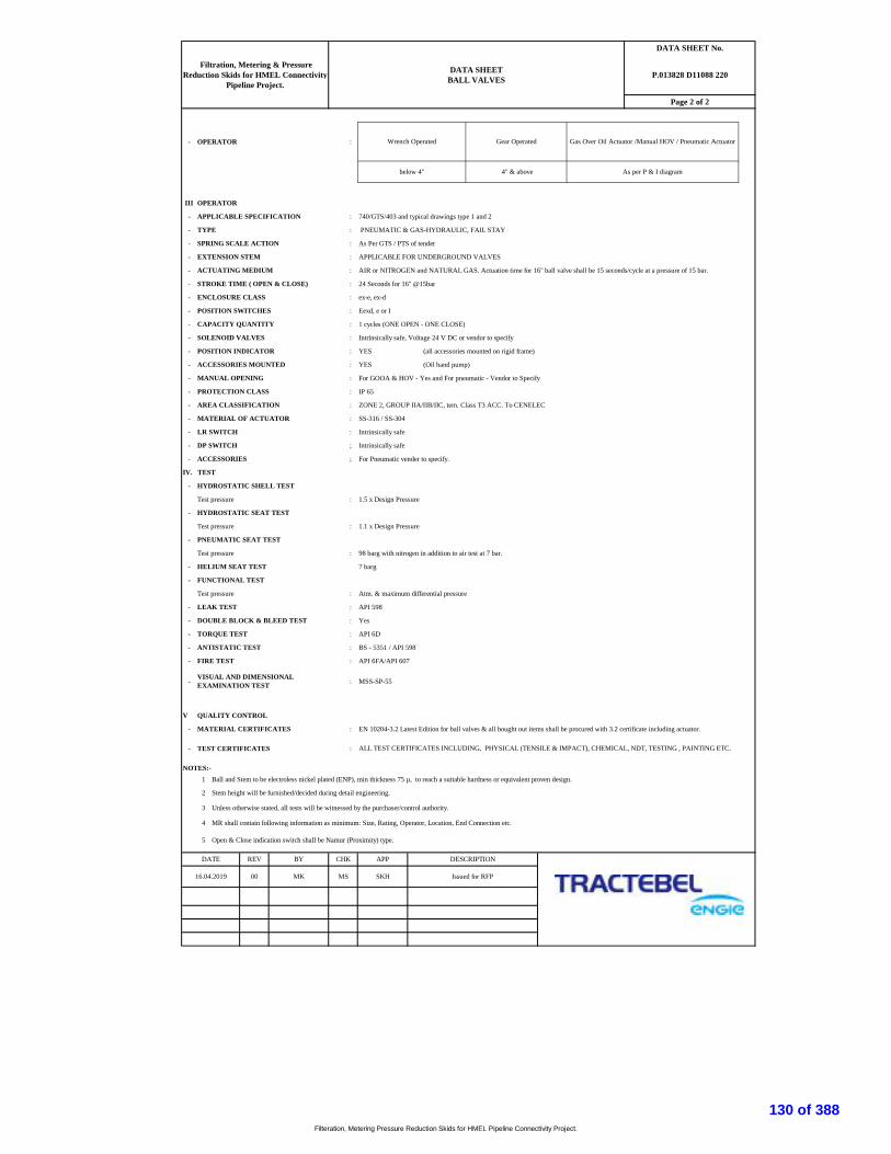
- OPERATOR :
III OPERATOR
- APPLICABLE SPECIFICATION : 740/GTS/403 and typical drawings type 1 and 2
- TYPE : PNEUMATIC & GAS-HYDRAULIC, FAIL STAY
- SPRING SCALE ACTION : As Per GTS / PTS of tender
- EXTENSION STEM : APPLICABLE FOR UNDERGROUND VALVES
- ACTUATING MEDIUM : AIR or NITROGEN and NATURAL GAS. Actuation time for 16" ball valve shall be 15 seconds/cycle at a pressure of 15 bar.
- STROKE TIME ( OPEN & CLOSE) : 24 Seconds for 16" @15bar
- ENCLOSURE CLASS : ex-e, ex-d
- POSITION SWITCHES : Eexd, e or I
- CAPACITY QUANTITY : 1 cycles (ONE OPEN - ONE CLOSE)
- SOLENOID VALVES : Intrinsically safe, Voltage 24 V DC or vendor to specify
- POSITION INDICATOR : YES (all accessories mounted on rigid frame)
- ACCESSORIES MOUNTED : YES (Oil hand pump)
- MANUAL OPENING : For GOOA & HOV - Yes and For pneumatic - Vendor to Specify
- PROTECTION CLASS : IP 65
- AREA CLASSIFICATION : ZONE 2, GROUP IIA/IIB/IIC, tem. Class T3 ACC. To CENELEC
- MATERIAL OF ACTUATOR : SS-316 / SS-304
- LR SWITCH : Intrinsically safe
- DP SWITCH ; Intrinsically safe
- ACCESSORIES ; For Pneumatic vender to specify.
IV. TEST
- HYDROSTATIC SHELL TEST
Test pressure : 1.5 x Design Pressure
- HYDROSTATIC SEAT TEST
Test pressure : 1.1 x Design Pressure
- PNEUMATIC SEAT TEST
Test pressure : 98 barg with nitrogen in addition to air test at 7 bar.
- HELIUM SEAT TEST 7 barg
- FUNCTIONAL TEST
Test pressure : Atm. & maximum differential pressure
- LEAK TEST : API 598
- DOUBLE BLOCK & BLEED TEST : Yes
- TORQUE TEST : API 6D
- ANTISTATIC TEST : BS - 5351 / API 598
- FIRE TEST : API 6FA/API 607
- : MSS-SP-55
V QUALITY CONTROL
- MATERIAL CERTIFICATES : EN 10204-3.2 Latest Edition for ball valves & all bought out items shall be procured with 3.2 certificate including actuator.
- TEST CERTIFICATES :
NOTES:-1 Ball and Stem to be electroless nickel plated (ENP), min thickness 75 µ, to reach a suitable hardness or equivalent proven design.
2 Stem height will be furnished/decided during detail engineering.
3 Unless otherwise stated, all tests will be witnessed by the purchaser/control authority.
4 MR shall contain following information as minimum: Size, Rating, Operator, Location, End Connection etc.
5 Open & Close indication switch shall be Namur (Proximity) type.
Issued for RFP
DESCRIPTIONAPP
Filtration, Metering & PressureReduction Skids for HMEL Connectivity
Pipeline Project.
BY
MS SKHMK
ALL TEST CERTIFICATES INCLUDING, PHYSICAL (TENSILE & IMPACT), CHEMICAL, NDT, TESTING , PAINTING ETC.
below 4" 4" & above
VISUAL AND DIMENSIONALEXAMINATION TEST
16.04.2019
DATE REV
00
CHK
As per P & I diagram
Page 2 of 2
P.013828 D11088 220
Wrench Operated Gear Operated
DATA SHEETBALL VALVES
Gas Over Oil Actuator /Manual HOV / Pneumatic Actuator
DATA SHEET No.
Filteration, Metering Pressure Reduction Skids for HMEL Pipeline Connectivity Project.
130 of 388
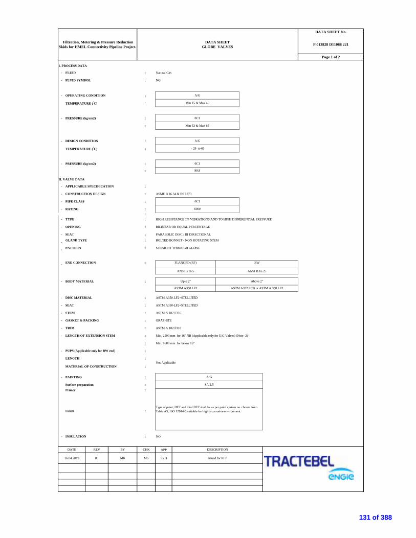
I. PROCESS DATA
- FLUID : Natural Gas
- FLUID SYMBOL : NG
- OPERATING CONDITION :
TEMPERATURE (°C) :
- PRESSURE (kg/cm2) :
:
- DESIGN CONDITION :
TEMPERATURE (°C) :
- PRESSURE (kg/cm2) :
:
II. VALVE DATA
- APPLICABLE SPECIFICATION :
- CONSTRUCTION DESIGN : ASME B.16.34 & BS 1873
- PIPE CLASS :
- RATING ::
- TYPE : HIGH RESISTANCE TO VIBRATIONS AND TO HIGH DIFFERENTIAL PRESSURE
- OPENING : BILINEAR OR EQUAL PERCENTAGE
- SEAT : PARABOLIC DISC / BI DIRECTIONAL
- GLAND TYPE : BOLTED BONNET - NON ROTATING STEM
- PATTERN : STRAIGHT THROUGH GLOBE
- END CONNECTION :
- BODY MATERIAL :
- DISC MATERIAL : ASTM A350-LF2+STELLITED
- SEAT : ASTM A350-LF2+STELLITED
- STEM : ASTM A 182 F316
- GASKET & PACKING : GRAPHITE
- TRIM : ASTM A 182 F316
- LENGTH OF EXTENSION STEM : Min. 2500 mm for 16" NB (Applicable only for U/G Valves) (Note -2)
: Min. 1600 mm for below 16"
- PUPS (Applicable only for BW end) :
LENGTH :
MATERIAL OF CONSTRUCTION :
- PAINTING :
Surface preparation :
Primer :
Finish :
- INSULATION : NO
APP
SKH
6C1
CHK
99.9
ANSI B 16.25
BY
DATA SHEET No.
P.013828 D11088 221DATA SHEETGLOBE VALVES
Page 1 of 2
16.04.2019
DATE REV
00
Filtration, Metering & Pressure ReductionSkids for HMEL Connectivity Pipeline Project.
A/G
Min 15 & Max 40
6C1
Min 53 & Max 65
A/G
- 29 to 65
A/G
SA 2.5
6C1
600#
ANSI B 16.5
BWFLANGED (RF)
Type of paint, DFT and total DFT shall be as per paint system no. chosen fromTable A5, ISO 12944-5 suitable for highly corrosive environment.
Upto 2"
ASTM A350 LF2
MK MS
DESCRIPTION
Issued for RFP
Not Applicable
Above 2"
ASTM A352 LCB or ASTM A 350 LF2
131 of 388

- OPERATOR :
III. TEST
- SHELL TEST : SEE API 598
- BACK SEAT TEST : SEE API 598
- LOW PRESSURE CLOSURE TEST : SEE API 598
- HIGH PRESSURE CLOSURE TEST : SEE API 598
- VISUAL EXAMINATION : SEE API 598
- HIGH PRESSURE SHELL TEST : SEE API 598
- FUNCTIONAL TEST : : SEE API 598
Pneumatic test at 7 barg shall be carried out in addition to above tests.
IV. QUALITY CONTROL
- MATERIAL CERTIFICATES : EN 10204 - 3.2
- ALL TEST CERTIFICATES :
NOTES:-
1 Unless otherwise stated, all tests shall be witnessed by the purchaser/control authority.
2 Stem height will be furnished/decided during detail engineering.
3 MR shall contain following information as minimum: Size, Rating, Operator, Location, End Connection etc.
4 Open & Close indication switch shall be Namur (Proximity) type.
ALL TEST CERTIFICATES INCLUDING, PHYSICAL (TENSILE & IMPACT), CHEMICAL, NDT, TESTING , PAINTING ETC.
DESCRIPTION
Issued for RFP
Filtration, Metering & PressureReduction Skids for HMEL Connectivity
Pipeline Project.
DATA SHEET No.
P.013828 D11088 221
SKH16.04.2019
DATE REV
00
BY
Hand wheel Operated Gear Operated
MK
CHK APP
MS
below 4" 4" & above
DATA SHEETGLOBE VALVES
Page 2 of 2
132 of 388

I. PROCESS DATA
- FLUID : Natural Gas
- FLUID SYMBOL : NG
- OPERATING CONDITION :
TEMPERATURE (°C)
- PRESSURE (kg/cm2)
- DESIGN CONDITION :
TEMPERATURE (°C)
- PRESSURE (kg/cm2)
II. VALVE DATA
- APPLICABLE SPECIFICATION :
- CONSTRUCTION DESIGN : API 6D
- DIMENSIONAL STANDARD : ANSI B 16.10
- PIPE CLASS :
- RATING :
- TYPE :
- END CONNECTION :
- BODY MATERIAL :
- WEDGE : ASTM A350-LF2 OR ASTM A 182 F6
- DISC : ASTM A350-LF2 OR ASTM A 182 F6
- HINGE PIN : ASTM A 182 F6
- GASKET : GRAPHITE
- PUPS (Applicable only for BW end) :
LENGTH
MATERIAL OF CONSTRUCTION
- PAINTING
Surface preparation :
Primer :
Finish :
- INSULATION : NO
APP
SKH
ASTM A352 LCB or ASTM A 350 LF2
BW
ANSI B 16.25
Type of paint, DFT and total DFT shallbe as per paint system no. chosen fromTable A5, ISO 12944-5 suitable forhighly corrosive environment. Finalshade of valve shall be Oxford Blue –RAL 5005.
Issued for RFP
Not Applicable
Above 2"
SWING CHECK
Upto 2"
ASTM A350 LF2
6C1
6C1
600#
Min 53 & Max 65
A/G
- 29 to 65
99.9
MK
FLANGED (RF)
ANSI B 16.5
A/G
DATA SHEETCHECK VALVES
BY CHK
MS
SA 2.5
A/G
DESCRIPTION
16.04.2019
DATE REV
00
Filtration, Metering & Pressure Reduction Skids forHMEL Connectivity Pipeline Project.
Page 1 of 2
Min 15 & Max 40
DATA SHEET No.
P.013828 D11088 222
6C1
Filtertion, Metering Pressure Reduction Skids for HMEL Connectivity Project.
133 of 388

III. TEST
- HYDROSTATIC SHELL TEST :
Test pressure : 1.5 x Design Pressure
- HYDROSTATIC SEAT TEST : : 1.1 x Design Pressure
- AIR SEAT TEST : 7 Barg
- HIGH PRESSURE CLOSURE TEST : API 598
- LOW PRESSURE CLOSURE TEST : API 598
- LEAK TEST : API 598
- FIRE SAFE TEST : API 6FA / API 6FD
- VISUAL & DIMENSIONAL EXAMINATION : YES
IV QUALITY CONTROL
- MATERIAL CERTIFICATES EN 10204-3.2
- ALL TEST CERTIFICATES
NOTES:-
1 Unless otherwise stated, all tests will be witnessed by the purchaser/control authority.
2 MR shall contain following information as minimum: Size, Rating, Operator, Location, End Connection etc.
3 Open & Close indication switch shall be Namur (Proximity) type.
DATA SHEETCHECK VALVES
Issued for RFP16.04.2019
DATE
MK
CHK APP
MS SKH
BY
P.013828 D11088 222
REV
00
ALL TEST CERTIFICATES INCLUDING, PHYSICAL (TENSILE & IMPACT), CHEMICAL, NDT, TESTING , PAINTING ETC.
Page 2 of 2
DESCRIPTION
Filtration, Metering & PressureReduction Skids for HMEL Connectivity
Pipeline Project.
DATA SHEET No.
Filtertion, Metering Pressure Reduction Skids for HMEL Connectivity Project.
134 of 388

QCT NoRev.Prepared byChecked byApproved by
Manufacturer
TPIA ControlAuthority
1
1.1 Pipe As per attached QCT Major laboratory +Dimensional
1 piece per pipesize ASTM A333 Gr 6 ASTM A333 Gr 6 Mfr / lab cert. P W/R W/R
Minor laboratory Per heat ASTM A 420 WPL6 ASTM A 420 WPL6 Mfr / lab cert. P W/R W/RMajor laboratory Per heat ASTM A 420 WPL6 ASTM A 420 WPL6 Mfr / lab cert. P W/R W/RMinor Visual 10% ANSI B16.9 ANSI B16.9 Mfr cert. P W/R W/RMinor laboratory 100% ASTM A350 LF2 ASTM A350 LF2 lab cert. P W/R W/RMajor laboratory Per heat ASTM A350 LF2 ASTM A350 LF2 Mfr / lab cert. P W/R W/RMinor Visual 10% ANSI 16.5 ANSI 16.5 Mfr cert. P W/R W/R
1.4 Stud and Bolts/ gaskets Chemical, physical andimpact test Minor Visual +10%
DimensionalRandom selection
one piece/sizeASME Sec II and ANSI
B1.1ASME Sec II and ANSI
B1.1 Mfr cert. P W/R W/R
1.5 Structure Dimentional Minor Visual +Dimensional 100% as per IS 2062 as per IS 2062 Mfr cert. P W/R W/R Fabricator W/S
2
2.1 WPS/WQP/PQR Welders Qualification &Welding Procedure Major
WeldersQualification &Welding Procedure
100% ApprovedWPS/WQR/PQR ASME Sec.IX WPS/WQP/PQR P R W/R
2.2 UT or DPTof Non Radiography forJoints DPT after Final Welding Major
DPT on other thanbutweld joints +UT Report
100% DPT Report + UTReport ASME + Sec. V DPT Report + UT
Report P 10%W W/R UT / DPT Report100% Review
2.3 Radiography Test Radiography after FinalWelding Major 100% Process
Piping 100% Radiography Report ASME Sec.VIII/ Div.1 &ASME Sec. V
RadiographyReport P * R * W/R * Film to be
Reviewed
2.4 Hydro Test for Interconnecting Pipespools (with 0.2% Inhibitor)
Hydro Test at 1.4 times theDesign Pressure Major Strength 100% GA Drawing and hydro
test procedureASME B 31.8,
IGE/TD/13. No Leakage Hydro Test Report P W W/R
2.5 Internal Cleaning of Pipe Spoolsafter Hydro Test. Internal Surface Finish Major Visual 100% Internal Report Internal Report Internal Report P R W/R
2.6 Surface Preparation and Painting ofSkid
Surface Preparation andPainting Major Visual + DFT
Measurement 100% Approved PaintingSpecification
Approved PaintingSpecification Inspection Report P W W/R
Random DFTMeasurementWitness
2.7 Pneumatic Leak Test for skid Pneumatic Leak Test at 7.7Bar for 30 min. Major leakage 100%
GA Drawing andPneumatic test
procedure attached
ASME B 31.8,IGE/TD/13. No Leakage Pneumatic Report P W W/R
2.8 Final Inspection of Assembled Skidwith all Instruments Tender Specs. Major Visual 100% GA Drawing + P&ID Approved Specification Internal Report P W W/R
2.9 Skid Preservation with N2 purging N2 Purging - 2Kg/cm2gPreservation-0.3Kg/cm2g Major Visual 100%
GA & N2Drg.+Preservation
ProcedureNo Leakage Internal Report P R W/R
2.10 Necessary Protection duringTransportation Major Visual 100% Protection Procedure Protection Procedure Internal Report P R W/R
Incoming Material for skid spool fabrication
Pipe Fittings
Flanges As per attached QCT
As per attached QCT
Acceptance Norms
SKH
Characteristic Type of Check
1.3
Welding, NDT & Testing for skid Piping fabrication
Class Remarks
P.013828 D 11013 209
Sr.No Description
00
Reference Document
MKNC
Format OfRecords
Inspection By
QUALITY CONTROL TABLESKID FABRICAITON FILTRATION AND METERING
1.2
Page 1 of 3
135 of 388

QCT NoRev.Prepared byChecked byApproved by
Manufacturer
TPIA ControlAuthority
Acceptance Norms
SKH
Characteristic Type of CheckClass Remarks
P.013828 D 11013 209
Sr.No Description
00
Reference Document
MKNC
Format OfRecords
Inspection By
QUALITY CONTROL TABLESKID FABRICAITON FILTRATION AND METERING
3
3.1 Ball Valve As per attached QCT Major As per attachedQCT
As per attachedQCT As per attached QCT Approved Specification MFR's TC P W/R W/R
3.2 Globe Valve / Check valve As per attached QCT Major As per attachedQCT
As per attachedQCT As per attached QCT Approved Data Sheet MFR's TC P W/R W/R
3.3 Pressure Safety Valve As per attached QCT Major As per attachedQCT 100% As per attached QCT Approved Data Sheet MFR's TC P W W/R
3.4Pressure &TemperatureTransmitter/Level Gauge, DPT,PGetc
As per attached QCT Major As per attachedQCT
As per attachedQCT Vendor's QCT Approved Data Sheet MFR's TC P W W/R
3.5 Turbine flow meter and FlowProfiler
Calibration, as per technicalspecifications Major
Dimensional,Visual, ModelOperation ofOrifice Assembly
100% Vendor's Manual Approved Data Sheet MFR's TC P W/R W/R
3.6 Panel / FC Physical / Electrical, asper technical specifications. Major Continuity check 100% Loop Diagram, Panel
GA Approved Data Sheet MFR's TC P W/R W/R
3.7 Natural Gas Filter As per attached QCT Major As per attachedQCT
As per attachedQCT As per attached QCT Approved Data Sheet MFR's TC P W/R W/R
3.8 SS Fittings As per attached QCT Major As per attachedQCT
As per attachedQCT As per attached QCT Approved Data Sheet MFR's TC P W/R W/R
3.9 Pressure Gauge, RTD &Thermowell As per attached QCT Major
Calibration,Dimensional,Range Model &Visual
100% Approved Data Sheet Approved Data Sheet MFR's TC P W/R W/R
3.10 Cable Test Reports Major MTC, Visual &Dimensional 100% MTC's, tender
Specification Approved Data Sheet MFR's TC P W/R W/R
3.11 Junction Box & Cable Gland Visual & DimensionalReview of Certificates Major Visual &
Dimensional 100% Approved P&ID and GADrawing
Approved P&ID and GADrawing MFR's TC P R W/R
4
4.1 Factory Acceptance Test (Panel) FAT as per Submitted FATManual Major FAT Procedure 100% Approved FAT Manual Approved FAT Manual Inspection Report P W W/R
4.2 Completeness + Inspection ReleaseCertificate (IRC) --- Major Visual +
Dimensions 100% Approved Bill ofMaterial
Approved Bill ofMaterial Inspection Report P W W/R
5
5.1 Dispatch --- Major Verification ofDocumentation 100% Verification of
DocumentationVerification ofDocumentation
DispatchCleatance by
Client--- R W/R
5.2 Name Plate Verification Name Plate Verification --- Name PlateVerification 100% Approved Drawing Approved Drawing Approved
Drawing --- R W/R
Final Inspection
Packing and Shipping Control
Incoming Material Identification of Boughtout Items
Page 2 of 3
136 of 388
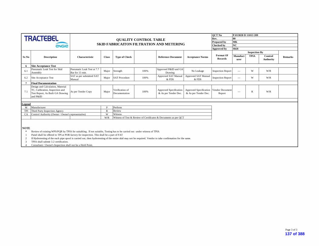
QCT NoRev.Prepared byChecked byApproved by
Manufacturer
TPIA ControlAuthority
Acceptance Norms
SKH
Characteristic Type of CheckClass Remarks
P.013828 D 11013 209
Sr.No Description
00
Reference Document
MKNC
Format OfRecords
Inspection By
QUALITY CONTROL TABLESKID FABRICAITON FILTRATION AND METERING
6
6.1 Pneumatic Leak Test for SkidAssembly
Pneumatic Leak Test at 7.7Bar for 15 min. Major Strength 100% Approved P&ID and GA
Drawing No Leakage Inspection Report --- W W/R
6.2 Site Acceptance Test SAT as per submitted SATManual Major SAT Procedure 100% Approved SAT Manual
& FDSApproved SAT Manual
& FDS Inspection Report --- W W/R
7
7.1
Design and Calculation, MaterialTC, Calibration, Inspection andTest Report, As Built GA Drawingand P&ID
As per Tender Copy Major Verification ofDocumentation 100% Approved Specification
& As per Tender Doc.Approved Specification& As per Tender Doc.
Vendor DocumentReport --- R W/R
M PTPI Third Party Inspection Agency RCA Control Authority (Owner / Owner's representative) W
W/R
NOTE*12 If Hydrotesting of the each pipe spool is carried out, then hydrotesting of the entire skid may not be required. Vendor to take confirmation for the same.3 TPIA shall submit 3.2 certification.4 Consultant / Owner's Inspection shall not be a Hold Point.
Review of existing WPS/PQR by TPIA for suitabling . If not suitable, Testing has to be carried out under witness of TPIAPanel shall be offered to TPI at POR factory for inspection. This shall be a part of FAT
Witness of Test & Review of Certificates & Documents as per QCTWitness
PerformReview
Manufacturer
Site Acceptance Test
Legend
Final Documentation
Page 3 of 3
137 of 388

QAP NoRev.Prepared by MK Checked by: NCApproved by
M TPI Consultant/Owner
1 Raw Material1.1 Castings/Forgings for Review of mfgr.s Test Major Visual Mat.speci.as per Mat.speci.as per Mfr cert. H R W/R
Body,Bonnet & Nozzle Certificates P. O. data sheet
1.2 Rods for Nozzles & Discs Physical/Chemical per Major Visual, Laboratory Mat.speci.as per Mat.speci.as per Mfr / lab cert. H R W/RRod P. O. data sheet
1.3 Finished bought out Review of mfgr.s Test Minor Visual, Dimensional Mat.speci.as per Mat.speci.as per Mfr cert. H R W/Rcomponents(Bellows & Certificates P. O. P. O.Springs)
2 Hydro test for Body & Shell Test Major Strength,Laboratory 100% ANSI B 16.34 For No Leakage Hydro Test Report H W W/RNozzle test pressure
3 Functional Test
3.1 Cold bench set pr. Popping at required Major Accuracy,Laboratory 100% As per P. O. As per P. O./API 526 Mfr / lab cert. H W W/Rcold bench set pr. ASME Std.VIII(Div.-1)
3.2 Seat tightness test Hydro/Airtest as per Major Accuracy,Laboratory 100% API 527 As per P. O. & Mfr / lab cert. H W W/Rflow media API 527
3.3 Back pressure test Air leak test Major Leakage,Laboratory 100% ASME Sect. VIII No leakage at Mfr / lab cert. H W W/RDiv.1/API 520 6.0 Kg/cm2(G)
3.4 Shell Pneumatic Test Functional Major Leakage,Laboratory 100% 100 psig Pneumatic Test Report H W W/R
4 Visual Examination Surface Quality Minor Visual 100% Material speci. Free from surface Mfr cert. H W W/Rdefects
5 Dimensional Check up Dimensions Major Dimensional 100% ANSI B 16.5/ ANSI B 16.5/ Mfr cert. H W W/RAPI 526 API 526
6 Painting applicable All Valves shall be Minor Visual 100% -- -- Mfr cert. H R W/R
painting with SM Grey
M PH R
CA WTPI W/R
NOTE : - Hydro test pressure - for Body as per outlet flange rating , '- for Nozzle as per inlet flange rating- for S-15 model Valves for Body & Nozzles - 1.5 times of set pr. & Rounded off to pressure corresponding to nearest ANSI Class
'- Cold set pressure = Set pr. - Back Pr. + Recommended Temp. correction Recommended temp. corrections are 67 to 120 - 1.0 % 121 to 200 - 2.0 % 316 to 430 - 4.0 % 431 to 450 - 5.0 %In case of Bellow effect of Back Pressure is negligible.
'- Seat tightness pr. = 90% of Cold bench set pressure for set pressure above 3.5Kg/cm2 (G) = Less 0.35 of cold bench set pressure if set pressure is below 3.5 Kg/cm2 (G)
LegendManufacturer PerformHold ReviewControl Authority (Owner / Owner's representative) WitnessThird Party Inspection Agency Witness of Test / Review of Certificates & Documents as per QAP
Format Of Records Remarks
Painting notapplicable for S.SValve.
Type of CheckQuantamof Check
ReferenceDocument
ClassDescription CharacteristicInspection By
Sr.No.
P.013828 D 11013 210: 00
SKH
QUALITY ASSURANCE PLANPRESSURE SAFETY VALVES
Acceptance Norms
Rev.0 Page 1 of 1138 of 388

Date: 16.04.2019 Revision: 00Prepared : MKChecked : MSApproved : SKH
GTS / PTS
chap. Manufacturer TPIA (By EPC Contractor) Client / Consultant
3 specification Perform review point review point6.1. specification Perform review point review point6.1. specification Perform review point review point
6.1. / 6.2.2. specification Perform hold point hold point
6.2.8. ASME B16.34 specification, Perform hold point hold point
6.3 specification, Data Sheet Perform review point review point
8.1, 8.2, 10.2 specification Perform review point review point
8.3 specification Perform review point review point8.5 specification Perform review point review point
8.6.6 specification Perform review point review point
11 specification Perform review point review point
GTS / PTS certif. 3.2 Perform hold point review point
GTS / PTS certif. 3.2 Perform hold point review point
- For CS at -200C Energy is35J/cm²(Avg.), 28J/cm²(Ind.) - For LTCS at -200C Energy is35J/cm²(Avg.), 28J/cm²(Ind.)and Material Standard’s impact testtemperature requirements or -450C,Whichever is lower.
certif. 3.2 Perform hold point review point
- ASME B 16.34, App IV ASME B 16.34, App IV certif. 3.2 Perform witness point review point- ASME B 16.34 ASME B 16.34 certif. 3.2 Perform review point review point
- ASME B 16.34 ASME B 16.34 certif. 3.2 Perform witness point review point
GTS / PTS certif. 3.2 Perform hold point review point
GTS / PTS certif. 3.2 Perform hold point review point
QAP No. : P.013828 D 11013 211
QUALITY ASSUARANCE PLAN BALL VALVES (Upto 12" Size)
CONTROL ON RECEIPT OF MATERIAL
- Fixation of Operation Methodology
Valve BODY:
Chemical Testing, Carbon Equivalent
7
Mechanical tests ( YS, TS, % EL, Ys / TS ratio, Micro /Macro, hardness etc)(Remark : marking transfer by TPIA)
Chemical Testing, Carbon Equivalent
Wet magnetic Particle Examination (100% External &accessible Internal)
Charpy-test at -20°C and as per Material requirement2 test sets (1 long./1 trans)(Remark : marking transfer by TPIA)
UT of Forging Body (100%)Radiography Test of Casting Body (100%)
FLANGES:
- heat treatment procedure
Sl.Nos.
- calculation of body bolting, Bonnet, Cover (For PressureRetaining Parts)
ACTIVITY
- pressure test procedure
1
CONTROL BEFORE MANUFACTURING
- material part list- dimensional drawings
Document type
- list of operation in manufacturing and control
- calculation butt welding ends
Acceptance criteriaApplied standard e/oProcedure
- qualified welding procedures/welders performancesqualification record
Scope of Inspection
- non destructive testing procedures
- painting procedure
Mechanical tests ( YS, TS, % EL, Ys / TS ratio, Micro /Macro, hardness etc)(Remark : marking transfer by TPIA)
Rev.00 Filtration, Metering Pressure Reduction Skids for HMEL Connectivity Pipeline Project. Page 1 of 5139 of 388

Date: 16.04.2019 Revision: 00Prepared : MKChecked : MSApproved : SKH
GTS / PTS
chap. Manufacturer TPIA (By EPC Contractor) Client / Consultant
QAP No. : P.013828 D 11013 211
QUALITY ASSUARANCE PLAN BALL VALVES (Upto 12" Size)
Sl.Nos. ACTIVITY Document typeAcceptance criteriaApplied standard e/o
Procedure
Scope of Inspection
- For CS at -200C Energy is35J/cm²(Avg.), 28J/cm²(Ind.) - For LTCS at -200C Energy is35J/cm²(Avg.), 28J/cm²(Ind.)and Material Standard’s impact testtemperature requirements or -450C,Whichever is lower.
certif. 3.2 Perform hold point review point
- ASME B 16.34, App IV ASME B 16.34, App IV certif. 3.2 Perform witness point review point
- ASME B 16.34 ASME B 16.34 certif. 3.2 Perform review point review point
ASME B 16.34 ASME B 16.34 certif. 3.2 Perform witness point review point
GTS / PTS certif. 3.2 Perform hold point review point
GTS / PTS certif. 3.2 Perform hold point review point
- For CS at -200C Energy is35J/cm²(Avg.), 28J/cm²(Ind.) - For LTCS at -200C Energy is35J/cm²(Avg.), 28J/cm²(Ind.)and Material Standard’s impact testtemperature requirements or -450C,Whichever is lower.
certif. 3.2 Perform hold point review point
- ASME B 16.34, App IV ASME B 16.34, App IV certif. 3.2 Perform witness point review point- ASME B 16.34 ASME B 16.34 certif. 3.2 Perform review point review point
- ASME B 16.34 ASME B 16.34 certif. 3.2 Perform witness point review point
- at -20°C, for Base/Weld/HAZ -35J/cm²(Avg.), 28J/cm²(Ind.). - at 0°C, for Base - 100J/cm²(Avg.),80J/cm²(Ind.),- at 0°C, for Weld/HAZ - 40J/cm²(Avg.),32J/cm²(Ind.)
certif. 3.2 Perform hold point review point
GTS / PTS certif. 3.2 Perform hold point RW
GTS / PTS certif. 3.2 Perform hold point RW
certif. 3.2 hold point review point
LATERAL CONNECTIONS:
- Mechanical tests ( YS, TS, % EL, Ys / TS ratio, Micro /Macro, hardness etc)(Remark : marking transfer by TPIA)
GTS / PTS
7
7
Chemical Testing, Carbon Equivalent
Charpy-test at -20°C and as per Material requirement2 test sets (1 long./1 trans.)(Remark : marking transfer by TPIA)
Mechanical tests(Remark : marking transfer by TPIA)
EXTENSION PIPE PIECES AS PER DATA SHEET
Chemical Testing, Carbon Equivalent
Charpy-test at -20°C and as per Material requirement2 test sets (1 long./1 trans.)(Remark : marking transfer by TPIA)
Mechanical tests ( YS, TS, % EL, Ys / TS ratio, Micro /Macro, hardness etc)(Remark : marking transfer by TPIA)
UT of Forging Body (100%)
Radiography Test of Casting Body (100%)
UT of Forging Body (100%)Radiography Test of Casting Body (100%)
Wet magnetic Particle Examination (100% External &accessible Internal)
Wet magnetic Particle Examination (100% External &accessible Internal)
Charpy-test at -20°C and as per Material requirement2 test sets (1 long./1 trans.)(Remark : marking transfer by TPIA)
BALL / OBTURATOR (Note -7):
Chemical Test, Carbon Equivalent
7
-
1A
Perform
Rev.00 Filtration, Metering Pressure Reduction Skids for HMEL Connectivity Pipeline Project. Page 2 of 5140 of 388
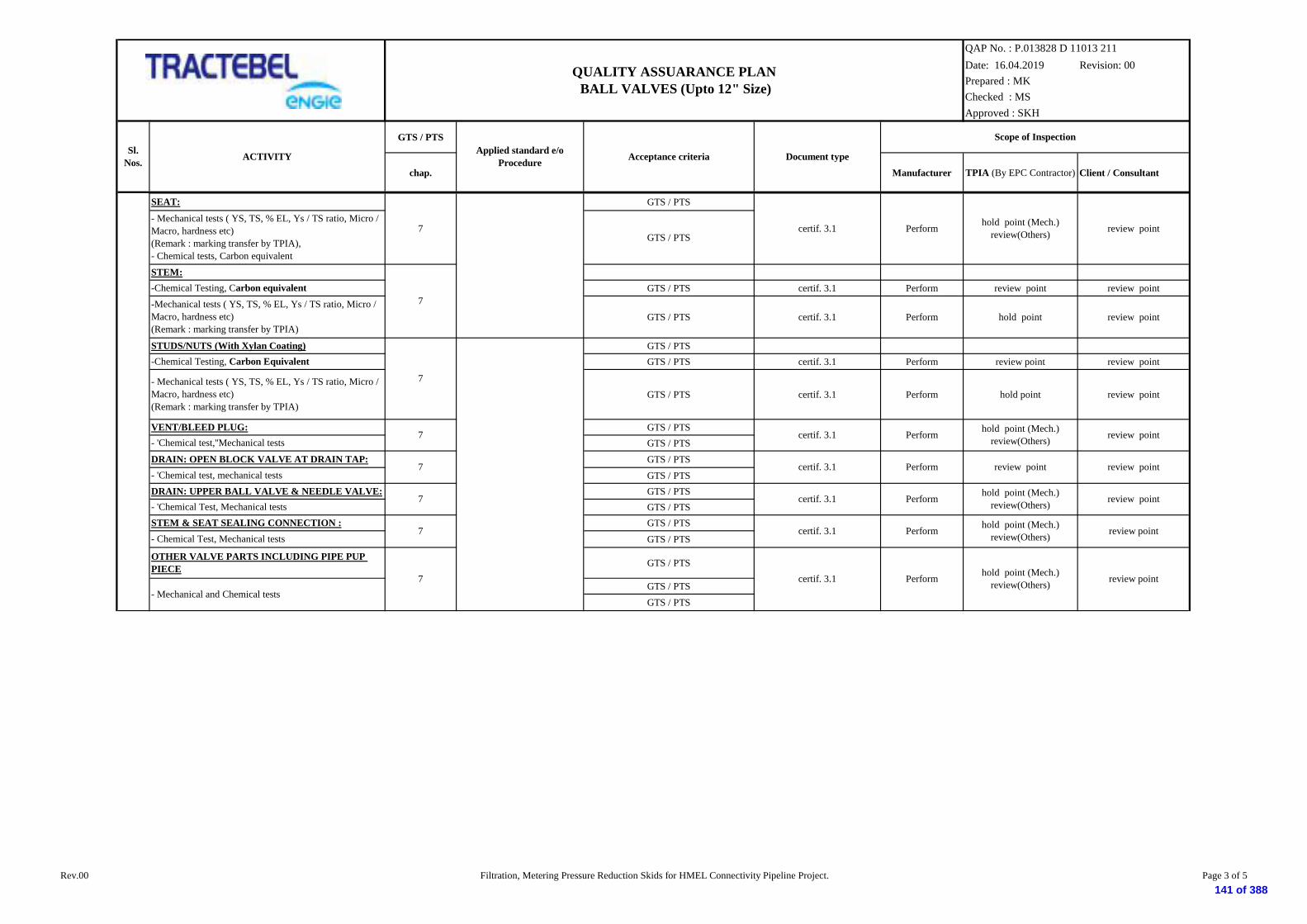
Date: 16.04.2019 Revision: 00Prepared : MKChecked : MSApproved : SKH
GTS / PTS
chap. Manufacturer TPIA (By EPC Contractor) Client / Consultant
QAP No. : P.013828 D 11013 211
QUALITY ASSUARANCE PLAN BALL VALVES (Upto 12" Size)
Sl.Nos. ACTIVITY Document typeAcceptance criteriaApplied standard e/o
Procedure
Scope of Inspection
GTS / PTS
GTS / PTS
GTS / PTS certif. 3.1 Perform review point review point
GTS / PTS certif. 3.1 Perform hold point review point
GTS / PTSGTS / PTS certif. 3.1 Perform review point review point
GTS / PTS certif. 3.1 Perform hold point review point
GTS / PTSGTS / PTSGTS / PTSGTS / PTSGTS / PTSGTS / PTSGTS / PTSGTS / PTS
GTS / PTS
GTS / PTSGTS / PTS
STEM & SEAT SEALING CONNECTION :
-Chemical Testing, Carbon Equivalent
-Chemical Testing, Carbon equivalent
- Mechanical tests ( YS, TS, % EL, Ys / TS ratio, Micro /Macro, hardness etc)(Remark : marking transfer by TPIA),- Chemical tests, Carbon equivalent
VENT/BLEED PLUG:- 'Chemical test,''Mechanical tests
review point
review point
review pointcertif. 3.1
OTHER VALVE PARTS INCLUDING PIPE PUPPIECE
7
hold point (Mech.)review(Others)- 'Chemical Test, Mechanical tests
certif. 3.1 hold point (Mech.)review(Others)7
- 'Chemical test, mechanical testsDRAIN: UPPER BALL VALVE & NEEDLE VALVE:
7
certif. 3.1
DRAIN: OPEN BLOCK VALVE AT DRAIN TAP:
- Chemical Test, Mechanical tests
7
certif. 3.1
certif. 3.1
hold point (Mech.)review(Others)
STEM:
hold point (Mech.)review(Others)
review point
review point
hold point (Mech.)review(Others) review pointcertif. 3.17
7
7
7
- Mechanical tests ( YS, TS, % EL, Ys / TS ratio, Micro /Macro, hardness etc)(Remark : marking transfer by TPIA)
SEAT:
-Mechanical tests ( YS, TS, % EL, Ys / TS ratio, Micro /Macro, hardness etc)(Remark : marking transfer by TPIA)
review point
STUDS/NUTS (With Xylan Coating)
- Mechanical and Chemical tests
Perform
Perform
Perform
Perform
Perform
Perform
Rev.00 Filtration, Metering Pressure Reduction Skids for HMEL Connectivity Pipeline Project. Page 3 of 5141 of 388
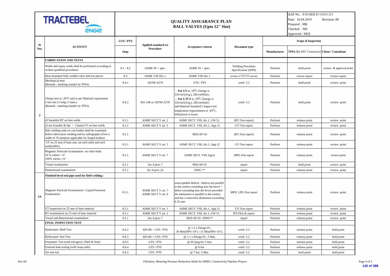
Date: 16.04.2019 Revision: 00Prepared : MKChecked : MSApproved : SKH
GTS / PTS
chap. Manufacturer TPIA (By EPC Contractor) Client / Consultant
QAP No. : P.013828 D 11013 211
QUALITY ASSUARANCE PLAN BALL VALVES (Upto 12" Size)
Sl.Nos. ACTIVITY Document typeAcceptance criteriaApplied standard e/o
Procedure
Scope of Inspection
8.1 - 8.2 ASME IX + spec. ASME IX + spec. Welding ProcedureSpecification (WPS) Perform hold point review & approval point
8.3 ASME VIII Div.1 ASME VIII Div.1 review CTT/TT curves Perform review report review report
8.4.1 ASTM A370 GTS / PTS certif. 3.2 Perform hold point review point
8.4.2 ISO 148 or ASTM A370
- For CS at -200C Energy is35J/cm²(Avg.), 28J/cm²(Ind.) - For LTCS at -200C Energy is35J/cm²(Avg.), 28J/cm²(Ind.)and Material Standard’s impact testtemperature requirements or -450C,Whichever is lower.
certif. 3.2 Perform hold point review point
8.5.1 ASME SECT V art. 2 ASME SECT. VIII, div.1, UW 51. (RT-Test report) Perform witness point review point
8.5.1 ASME SECT V art. 5 ASME SECT. VIII, div.1, App.12 UT-Test report Perform witness point review point
8.5.1 MSS-SP-54 (RT-Test report) Perform witness point review point
8.5.1 ASME SECT V art. 5 ASME SECT. VIII, dic.1, App.12 UT-Test report Perform witness point review point
8.5.1 ASME SECT V art. 7 ASME SECT. VIII App.6 MPE-Test report Perform witness point review point
8.5.1 Sec 8 proc.7 MSS-SP-55 report Perform hold point review point
8.5.1 Sec 8 proc.24 DWG ** report Perform witness point review point
Finished bevel end pipe used for field welding :
8.5.1 ASME SECT V art. 7ASME SECT V art. 6
unacceptable defects : defects not parallelto the surface extending into the bevel +defect extending into the bevel providedthe lamination is parallel to the surfaceand has a transverse dimension exceeding6.35 mm
MPE/ LPE-Test report Perform witness point review point
8.5.1 ASME SECT V art. 5 ASME SECT. VIII, div.1, App.12 UT-Test report Perform witness point review point8.5.1 ASME SECT V art. 2 ASME SECT. VIII, div.1, UW 51. RT-Film & report Perform witness point review point8.5.1 Sec 8 proc.7 MSS-SP-55 +DWG** report Perform witness point review point
8.6.2 API 6D + GTS / PTS @ 1.5 x Design Pr.,30 Min(NPS>18") / 15 Min(NPS<16"). certif. 3.2 Perform witness point hold point
8.6.3 API 6D + GTS / PTS @ 1.1 x Design Pr., 5 Min. certif. 3.2 Perform witness point hold point
8.6.5 GTS / PTS @ 95 barg for 5 min. certif. 3.2 Perform witness point hold point
8.6.4 GTS / PTS @ 6 bar certif. 3.2 Perform witness point hold point
8.6.5 GTS / PTS @ 7 bar, 5 Min. certif. 3.2 Perform hold point hold point
Heat treatment fully welded valve and test pieces
Magnetic Particule Examination on valve body10 % valves < 6"100% valves 6"
FABRICATION AND TESTS
Hydrostatic Seat Test
Air seat test
Visual and dimensional examination
(if not feasable & thk. > 15mm) UT on butt welds
RT examination on 25 mm of base material
Butt welding ends on cast bodies shall be examinedbefore fabrication welding end by radiography (Over awidth of 70 mm)(not applicable for forged bodies)
FINAL INSPECTION TEST
2A
2
Pneumatic Test (with nitrogen) ( Shell & Seat)
Visual examination
Dimensional examination
Hydrostatic Shell Test
(if feasable) RT on butt welds
UT inspection on 25 mm of base material
Welds and repair welds shall be performed according towritten qualified procedures
Mechanical tests(Remark : marking transfer by TPIA)
Charpy-test at -20°C and as per Material requirement2 test sets (1 long./1 trans.)(Remark : marking transfer by TPIA)
UT on 25 mm of base mat. (at each side) and eachweld(100%)
Magnetic Particule Examination / Liquid PenetrantExamination
External leak testing (with Soup suds)
Rev.00 Filtration, Metering Pressure Reduction Skids for HMEL Connectivity Pipeline Project. Page 4 of 5142 of 388
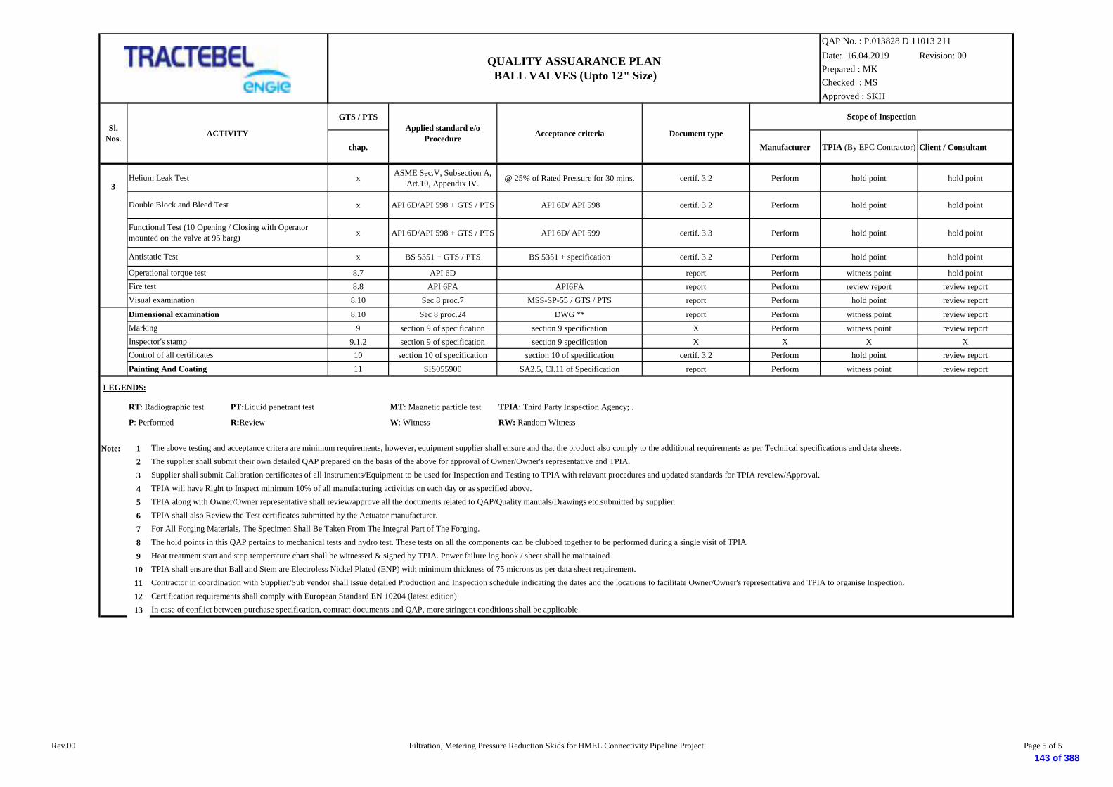
Date: 16.04.2019 Revision: 00Prepared : MKChecked : MSApproved : SKH
GTS / PTS
chap. Manufacturer TPIA (By EPC Contractor) Client / Consultant
QAP No. : P.013828 D 11013 211
QUALITY ASSUARANCE PLAN BALL VALVES (Upto 12" Size)
Sl.Nos. ACTIVITY Document typeAcceptance criteriaApplied standard e/o
Procedure
Scope of Inspection
x ASME Sec.V, Subsection A,Art.10, Appendix IV. @ 25% of Rated Pressure for 30 mins. certif. 3.2 Perform hold point hold point
x API 6D/API 598 + GTS / PTS API 6D/ API 598 certif. 3.2 Perform hold point hold point
x API 6D/API 598 + GTS / PTS API 6D/ API 599 certif. 3.3 Perform hold point hold point
x BS 5351 + GTS / PTS BS 5351 + specification certif. 3.2 Perform hold point hold point
8.7 API 6D report Perform witness point hold point8.8 API 6FA API6FA report Perform review report review report
8.10 Sec 8 proc.7 MSS-SP-55 / GTS / PTS report Perform hold point review report
8.10 Sec 8 proc.24 DWG ** report Perform witness point review report9 section 9 of specification section 9 specification X Perform witness point review report
9.1.2 section 9 of specification section 9 specification X X X X10 section 10 of specification section 10 of specification certif. 3.2 Perform hold point review report11 SIS055900 SA2.5, Cl.11 of Specification report Perform witness point review report
RT: Radiographic test PT:Liquid penetrant test MT: Magnetic particle test TPIA: Third Party Inspection Agency; .
P: Performed R:Review W: Witness RW: Random Witness
Note: 123456789
10111213
Visual examination
3
Functional Test (10 Opening / Closing with Operatormounted on the valve at 95 barg)
Dimensional examination
The supplier shall submit their own detailed QAP prepared on the basis of the above for approval of Owner/Owner's representative and TPIA.
Contractor in coordination with Supplier/Sub vendor shall issue detailed Production and Inspection schedule indicating the dates and the locations to facilitate Owner/Owner's representative and TPIA to organise Inspection.
Supplier shall submit Calibration certificates of all Instruments/Equipment to be used for Inspection and Testing to TPIA with relavant procedures and updated standards for TPIA reveiew/Approval.TPIA will have Right to Inspect minimum 10% of all manufacturing activities on each day or as specified above.TPIA along with Owner/Owner representative shall review/approve all the documents related to QAP/Quality manuals/Drawings etc.submitted by supplier.TPIA shall also Review the Test certificates submitted by the Actuator manufacturer.
The above testing and acceptance critera are minimum requirements, however, equipment supplier shall ensure and that the product also comply to the additional requirements as per Technical specifications and data sheets.
Double Block and Bleed Test
Antistatic Test
For All Forging Materials, The Specimen Shall Be Taken From The Integral Part of The Forging.The hold points in this QAP pertains to mechanical tests and hydro test. These tests on all the components can be clubbed together to be performed during a single visit of TPIAHeat treatment start and stop temperature chart shall be witnessed & signed by TPIA. Power failure log book / sheet shall be maintained
LEGENDS:
Certification requirements shall comply with European Standard EN 10204 (latest edition)In case of conflict between purchase specification, contract documents and QAP, more stringent conditions shall be applicable.
Marking
Operational torque testFire test
Helium Leak Test
TPIA shall ensure that Ball and Stem are Electroless Nickel Plated (ENP) with minimum thickness of 75 microns as per data sheet requirement.
Painting And Coating
Inspector's stampControl of all certificates
Rev.00 Filtration, Metering Pressure Reduction Skids for HMEL Connectivity Pipeline Project. Page 5 of 5143 of 388

Date: 16.04.2019 Revision: 00Prepared : MKChecked : MSApproved : SKH
Manufacturer TPIA (By EPC Contractor) Client / Consultant
Perform review point review point
Perform review point review point
Perform review point review point
Perform hold point hold point
ASME B16.34 specification, Perform hold point hold point
specification, Data Sheet Perform review point review point
specification Perform review point review point
specification Perform review point review point
specification Perform review point review point
specification Perform review point review point
specification Perform review point review point
2 CONTROL ON RECEIPT OF MATERIAL
2.1 Casts
ASME V, Art.2
ASME VIII-1, App.7ASME B31.3(Latest), Table 341.3.2A,
Severe Cyclic cond.
certif. 3.2
Perform
review point review point
ASME V, Art.6 -ASTM E-165 ASME VIII-1, App.7 & 8
certif. 3.2Perform witness point
review point
ASME V, Art.7 ASME VIII-1, App.6 & 7 certif. 3.2 Perform witness point review point
2.1.2 Referred API / ASTM Referred API / ASTM certif. 3.2 Perform witness point review point
As per tender specification / data Sheet /Ref Std.
Document type
- list of operation in manufacturing and control
- calculation butt welding ends
Acceptance criteria
- heat treatment procedure
QAP No. : P.013828 D 11013 212
QUALITY ASSURANCE PLANGLOBE & CHECK VALVES
Sl.Nos.
- calculation of body bolting, Bonnet, Cover (For Pressure RetainingParts)
ACTIVITY
- material part list
- pressure test procedure
- dimensional drawings
- painting procedure
- qualified welding procedures/welders performances qualificationrecord
As per tender specification /data Sheet / Ref Std.
- Fixation of Operation Methodology1
CONTROL BEFORE MANUFACTURING
2.1.1 Non Destructive TestingRadiography Testing - 100%: each type / size / rating
Penetrant Testing - 100%: each type / size / rating
Applied standard e/oProcedure
- non destructive testing procedures
Magnetic Particle Testing - (alternative for PT)
Scope of Inspection
Chemical analysis, Carbon Equivalent (each heat and product)
Rev - 00 Filtertion, Metering Pressure Reduction Skids for HMEL Connectivity Pipeline Project. Page 1 of 5
144 of 388

Date: 16.04.2019 Revision: 00Prepared : MKChecked : MSApproved : SKH
Manufacturer TPIA (By EPC Contractor) Client / ConsultantDocument typeAcceptance criteria
QAP No. : P.013828 D 11013 212
QUALITY ASSURANCE PLANGLOBE & CHECK VALVES
Sl.Nos. ACTIVITY
CONTROL BEFORE MANUFACTURING
Applied standard e/oProcedure
Scope of Inspection
2.1.3 Referred API / ASTM Referred API / ASTM certif. 3.2 Perform witness point Random Witness point
2.1.4 ASTM A-370
- For CS at -20°C Energy is35J/cm²(Avg.), 28J/cm²(Ind.) - For LTCS at -20°C Energy is35J/cm²(Avg.), 28J/cm²(Ind.)and Material Standard’s impact testtemperature requirements or -450C,Whichever is lower.
certif. 3.2 Perform witness point Random Witness point
2.2 Forgings
ASME V, Art.6ASME VIII-1, App.8 certif. 3.2
Perform review point review point
ASME B 16.34, app. IV /ASME Sec V Art 5
ASME B 16.34, app. IV / ASME Sec VDiv 1 UF 55
certif. 3.2Perform review point review point
ASME V, Art.7 ASME VIII-1, App.6certif. 3.2
Perform witness point review point
2.2.2 Referred API / ASTM Referred API / ASTM certif. 3.2 Perform witness point review point
2.2.3 Referred API / ASTM Referred API / ASTM certif. 3.2 Perform witness point Random Witness point
2.2.4 ASTM A-370
- For CS at -20°C Energy is35J/cm²(Avg.), 28J/cm²(Ind.) - For LTCS at -20°C Energy is35J/cm²(Avg.), 28J/cm²(Ind.)and Material Standard’s impact testtemperature requirements or -450C,Whichever is lower.
certif. 3.2 Perform witness point Random Witness point
Ultrasonic Testing - 100%: on Body & Bonnet
Non Destructive Testing
Penetrant Testing - 10%: on Disc / Wedge & Stem after final machining
Magnetic Particle Testing - 100% on pressure retaining parts
2.2.1
Chemical analysis, Carbon Equivalent (each heat and product)
Mechanical tests (YS, UTS, YS/UTS, %EL, RA, Bend etc. asapplicable) - on samples taken from mill.(Remark : marking transfer by TPIA)
Charpy Impact test - 2 test sets (1 Longitudinal & 1 Transverse)(Remark : marking transfer by TPIA)
Mechanical tests (YS, UTS, YS/UTS, %EL, RA, Bend, Micro / macro,hardness etc. as applicable) - on samples taken from mill.(Remark : marking transfer by TPIA)
Charpy Impact test - 2 test sets (1 Longitudinal & 1 Transverse)(Remark : marking transfer by TPIA)
Rev - 00 Filtertion, Metering Pressure Reduction Skids for HMEL Connectivity Pipeline Project. Page 2 of 5
145 of 388

Date: 16.04.2019 Revision: 00Prepared : MKChecked : MSApproved : SKH
Manufacturer TPIA (By EPC Contractor) Client / ConsultantDocument typeAcceptance criteria
QAP No. : P.013828 D 11013 212
QUALITY ASSURANCE PLANGLOBE & CHECK VALVES
Sl.Nos. ACTIVITY
CONTROL BEFORE MANUFACTURING
Applied standard e/oProcedure
Scope of Inspection
2.3 As per Approved Procedure /Purchase Specification
As per Approved Procedure / PurchaseSpecification certif. 3.2 Perform witness point review point
2.4
2.4.1 ASME V, Art.6 ASME VIII-1, App.8 certif. 3.2 Perform review point review point
2.4.2 Referred ASTM Referred ASTM certif. 3.2 Perform witness point review point
2.4.3 Referred API / ASTM Referred API / ASTM certif. 3.2 Perform witness point review point
2.4.4 Referred API / ASTM Referred API / ASTM certif. 3.2 Perform witness point Random Witness point
2.4.5 ASTM A-370 As per material specification certif. 3.2 Perform witness point Random Witness point
2.5 Compliance to purchase order Purchase Specification report Perform review point review point
2.6 100 % RT ASME V, Art. 2 ASME B31.3(1990), Table 341.3.2A,severe cyclic cond. report Perform witness point review point
2.7 100 % RT ASME V, Art. 2 &ASME IX
ASME B31.3(1990), Table 341.3.2A,severe cyclic cond. report Perform witness point review point
Plate: Cover, Disc, Seat Ring Flap, Arm (Chemical & MechanicalProperties)
Chemical analysis, Carbon Equivalent (each heat and product)
Mechanical tests (YS, UTS, YS/UTS, %EL, RA, Bend etc. asapplicables) - on samples taken from mill.(Remark : marking transfer by TPIA)
Charpy Impact test as per Material specification requirement2 test sets (1 long./1 trans.)(Remark : marking transfer by TPIA)
Welds & weld repairs - each piece
Actuators (If Applicable)
BW ends - each piece.
Penetrant Testing (on each batch after final machining)
Heat Treatment (on each Heat Treatment batch)
Bolting/ Fasteners
Rev - 00 Filtertion, Metering Pressure Reduction Skids for HMEL Connectivity Pipeline Project. Page 3 of 5
146 of 388

Date: 16.04.2019 Revision: 00Prepared : MKChecked : MSApproved : SKH
Manufacturer TPIA (By EPC Contractor) Client / ConsultantDocument typeAcceptance criteria
QAP No. : P.013828 D 11013 212
QUALITY ASSURANCE PLANGLOBE & CHECK VALVES
Sl.Nos. ACTIVITY
CONTROL BEFORE MANUFACTURING
Applied standard e/oProcedure
Scope of Inspection
certif. 3.2 Perform witness point Random Witness point
certif. 3.2 Perform witness point Random Witness point
certif. 3.2 Perform witness point Random Witness point
certif. 3.2 Perform witness point Random Witness point
certif. 3.2 Perform witness point Random Witness point
certif. 3.2 Perform witness point Random Witness point
certif. 3.2 Perform witness point Random Witness point
certif. 3.2 Perform witness point Random Witness point
report Perform witness point Random Witness point
report Perform witness point Random Witness point
API 6FA / API 607 / BS 5146/ OCMA API 6FA / API 607 / BS 5146 / OCMA report Perform review report Random Witness point
Open, Close time, Torque,Limit setting Functioning in Hydrostatic Test report Perform witness point hold point
ASME Sec-V, Art.9 Refered ANSI dimensions report Perform hold point review report
Actuator Functional Test (If applicable)
Cyclic Pressure Test - 1 Valve per size (6" & above)(10 Open - Close - Open cycles with Maximum diffrential pressure)
Cyclic Pressure Test - 1 per valve per size ( 6"& above) ( 10 OpenClose - Open Cycles with Maximum differential Pressure)
Visual & Dimensional examination
Fire safe tested (Type Test)(Certificates of previously conducted tests shall be submitted)
Pneumatic Shell & Seat Test (at 7 Bar with Nitrogen)
Helium Leak Test (duration minimum 30 min) BS 1873 / API 598 / ASME B16.34 /ASTM A-530 & Data Sheet
Torque Test
High Pressure Closure Test & Low Pressure Closure Test(3 Opening & Closure at Atmospheric & Maximum diffrential pressure)
FINAL INSPECTION TEST
Hydrostatic Back Seat Test (duration minimum 30 min)
BS 1873 / API 598 / ASMEB16.34 / ASTM A-530 &
Data Sheet
3
Hydrostatic Shell Test (duration minimum 15 min)
Hydrostatic Seat Test (duration minimum 30 min)
Air seat test (duration minimum 5 min)
Rev - 00 Filtertion, Metering Pressure Reduction Skids for HMEL Connectivity Pipeline Project. Page 4 of 5
147 of 388

Date: 16.04.2019 Revision: 00Prepared : MKChecked : MSApproved : SKH
Manufacturer TPIA (By EPC Contractor) Client / ConsultantDocument typeAcceptance criteria
QAP No. : P.013828 D 11013 212
QUALITY ASSURANCE PLANGLOBE & CHECK VALVES
Sl.Nos. ACTIVITY
CONTROL BEFORE MANUFACTURING
Applied standard e/oProcedure
Scope of Inspection
As per Approved procedure As per Approved procedure Perform witness point review report
As per Approved procedure As per Approved procedure X Perform witness point review report
- - X Perform hold point review report
- - certif. 3.2 Perform hold point review report
LEGENDS:RT: Radiographic test PT:Liquid penetrant test MT: Magnetic particle test TPIA: Third Party Inspection Agency; .P: Performed R:Review W: Witness Control Authority : Owner/Engineer or their Authorised Inspection Agency
Notes: 1
23456
7
89
10111213
Surface Preparation, Painting & Preservation
Marking
Inspector's stamp
The supplier shall submit their own detailed QAP prepared on the basis of the above for approval of Owner/Owner's representative and TPIA.
Certification requirements shall comply with European Standard EN 10204 (latest edition)
The Above Testing and acceptance critera are minimum requirements, however, equipment supplier shall ensure and that the product also comply to the additional requirements as per Technical specifications and data sheets. TPIA shall issuethe EN10204 3.2 Certification for the Final Product. Welding & Welder Qualification "W" for Customer/CA. Heat treatment as per Specification.
Control of all certificates
The hold points in this QAP pertains to mechanical tests and hydro test. These tests on all the components can be clubbed together to be performed during a single visit of TPIA
Contractor shall in coordination with Supplier/Sub vendor shall issue detailed Production and Inspection schedule indicating the dates and the locations to facilitate Owner/Owner's representative and TPIA to organise Inspection.
Supplier shall submit Calibration certificates of all Instruments/Equipment to be used for Inspection and Testing to TPIA with relavant procedures and updated standards for TPIA reveiew/Approval.TPIA will have Right to Inspect minimum 10% of all manufacturing activities on each day or as specified above.TPIA along with Owner/Owner representative shall review/approve all the documents related to QAP/Quality manuals/Drawings etc.submitted by supplier.
All bought out items will be procured with 3.2 Certificates.
TPIA shall also Review the Test certificates submitted by the Actuator manufacturer.
4
For All Forging / Casting Materials, The Specimen Shall Be Taken From The Integral Part of The Forging / CastingHeat treatment start and stop temperature chart shall be witnessed & signed by TPIA. Power failure log book / sheet shall be maintainedIn case of conflict between purchase specification, contract documents and QAP, more stringent conditions shall be applicable.
Rev - 00 Filtertion, Metering Pressure Reduction Skids for HMEL Connectivity Pipeline Project. Page 5 of 5
148 of 388
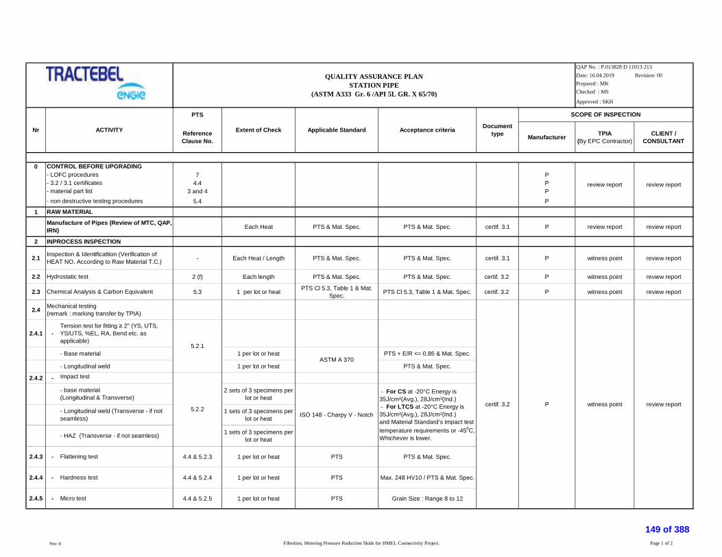
Date: 16.04.2019 Revision: 00Prepared : MKChecked : MS
Approved : SKH
PTS
ReferenceClause No. Manufacturer TPIA
(By EPC Contractor)CLIENT /
CONSULTANT
07 P
4.4 P3 and 4 P
5.4 P
1
Each Heat PTS & Mat. Spec. PTS & Mat. Spec. certif. 3.1 P review report review report
2 INPROCESS INSPECTION
2.1 - Each Heat / Length PTS & Mat. Spec. PTS & Mat. Spec. certif. 3.1 P witness point review report
2.2 2 (f) Each length PTS & Mat. Spec. PTS & Mat. Spec. certif. 3.2 P witness point review report
2.3 5.3 1 per lot or heat PTS Cl 5.3, Table 1 & Mat.Spec. PTS Cl 5.3, Table 1 & Mat. Spec. certif. 3.2 P witness point review report
2.4
2.4.1 -
- Base material 1 per lot or heat PTS + E/R <= 0.85 & Mat. Spec.
- Longitudinal weld 1 per lot or heat PTS & Mat. Spec.
2.4.2 - Impact test
2 sets of 3 specimens perlot or heat
1 sets of 3 specimens perlot or heat
1 sets of 3 specimens perlot or heat
2.4.3 - 4.4 & 5.2.3 1 per lot or heat PTS PTS & Mat. Spec.
2.4.4 - 4.4 & 5.2.4 1 per lot or heat PTS Max. 248 HV10 / PTS & Mat. Spec.
2.4.5 - 4.4 & 5.2.5 1 per lot or heat PTS Grain Size : Range 8 to 12
witness point
- For CS at -20°C Energy is35J/cm²(Avg.), 28J/cm²(Ind.) - For LTCS at -20°C Energy is35J/cm²(Avg.), 28J/cm²(Ind.)and Material Standard’s impact testtemperature requirements or -450C,Whichever is lower.
- Longitudinal weld (Transverse - if notseamless)
- HAZ (Transverse - if not seamless)
Flattening test
Hardness test
Micro test
Mechanical testing(remark : marking transfer by TPIA)
Tension test for fitting 2" (YS, UTS,YS/UTS, %EL, RA, Bend etc. asapplicable)
- base material(Longitudinal & Transverse)
Manufacture of Pipes (Review of MTC, QAP,IRN)
RAW MATERIAL
P
Chemical Analysis & Carbon Equivalent
Inspection & Identificattion (Verification ofHEAT NO. According to Raw Material T.C.)
Hydrostatic test
QUALITY ASSURANCE PLANSTATION PIPE
(ASTM A333 Gr. 6 /API 5L GR. X 65/70)
QAP No. : P.013828 D 11013 213
certif. 3.2
5.2.1
ASTM A 370
5.2.2review report
- LOFC procedures
ISO 148 - Charpy V - Notch
review report
Nr DocumenttypeApplicable Standard Acceptance criteriaACTIVITY Extent of Check
CONTROL BEFORE UPGRADING
- 3.2 / 3.1 certificates
- non destructive testing procedures- material part list
SCOPE OF INSPECTION
review report
Rev -0 Filtertion, Metering Pressure Reduction Skids for HMEL Connectivity Project. Page 1 of 2
149 of 388

Date: 16.04.2019 Revision: 00Prepared : MKChecked : MS
Approved : SKH
PTS
ReferenceClause No. Manufacturer TPIA
(By EPC Contractor)CLIENT /
CONSULTANT
QUALITY ASSURANCE PLANSTATION PIPE
(ASTM A333 Gr. 6 /API 5L GR. X 65/70)
QAP No. : P.013828 D 11013 213
Nr DocumenttypeApplicable Standard Acceptance criteriaACTIVITY Extent of Check
SCOPE OF INSPECTION
3 Non Destructive Testings
3.1 Magnetic Particle Testing All pipes Bevel Ends ASME SEC. VIII DIV. 2 ARTICLE7.5.6.2 P witness point review report
100% of complete surface &welds (if any)
ASME, sectionVIII, division1appendix 12
100% bevels
- defects extending into the bevelprovided the lamination is parallel tothe surface and has a transversedimension exceeding 6.35 mm- all defects not parallel to thesurface extending into the bevel
4 FINAL INSPECTION TEST
4.1 5.1 All accepted pipes PTS & Mat. Spec. PTS & Mat. Spec. certif. 3.2 P witness point review report
4.1 7 All accepted pipes PTS & Mat. Spec. PTS & Mat. Spec. certif. 3.2 P witness point review report
4.2 8 All accepted pipes PTS & Mat. Spec. PTS & Mat. Spec. certif. 3.2 Hold Point witness point witness point
LEGEND:RT: Radiographic test PT: Liquid penetrant test MT: Magnetic particle test HT: Heat treatment TPIA: Third Party Inspection AgencyP: Performed R: Review W: Witness VT: Visual test
Note: 1
2
3
4
5
6
7
89
P3.2
Visual & Dimensional
The supplier shall submit their own detailed QAP prepared on the basis of the above for approval of Owner/Owner's representative and TPIA.
Certification requirements shall comply with European Standard EN 10204:3.2 (latest edition)
Ultrasonic Testing
TPIA will have Right to Inspect minimum 10% of all manufacturing activities on each day or as specified above.
TPIA along with Owner/Owner representative shall review/approve all the documents related to QAP/Quality manuals/Drawings etc.submitted by supplier.
Contractor in coordination with Sub-vendor shall issue detailed Production and Inspection schedule indicating the dates and the locations to facilitate Owner/Owner's representative and TPIA to organise Inspection.
The Above Testing and acceptance critera are minimum requirements, however, equipment supplier shall ensure that the product also comply to the additional requirements as per Technical specifications and data sheets.
Supplier shall submit Calibration certificates of all Instruments/Equipment to be used for Inspection and Testing to TPIA with relavant procedures and updated standards for TPIA reveiew/Approval.
Marking & Tagging
Loaction of Thickness Chechked by TPIA shall be marked with Paint.
Inspector's stamp
review report5.4 All pipes certif. 3.2
In case of conflict between purchase specification, contract documents and QAP, more stringent conditions shall be applicable.
witness point
Rev -0 Filtertion, Metering Pressure Reduction Skids for HMEL Connectivity Project. Page 2 of 2
150 of 388

Date: 16.04.2019 Revision: 00Prepared : MKChecked : MSApproved : SKH
PTS
chap. Manufacturer TPIA (By EPCContractor) Client / Consultant
0
9.1 1 per purchase order specification Perform review point review point
- Fabrication and Control procedure 9.1 specification Perform review point review point
9.1; 2 and 3 specification Perform review point review point
9.2 ; 2 specification Perform review point review point
2, 4, 5, 6 & 7 specification Perform review point review point
6 specification Perform review point review point
As per PTS specification Perform review point review point
1 BASE MATERIAL
5.1.1 1 per lot* PTS / Mat. Spec. certif. 3.2 Perform hold point review report
5.1.2 1 per lot* (1 set of 3specimen per temp. range) PTS / Mat. Spec. certif. 3.2 Perform hold point review report
CHEMICAL COMPOSITION
Check chemical analysis 3.10 1 per heat PTS-Table1 Perform review report review report
2 FABRICATION AND TESTS
2.1. 4.3 all fittings T/T Graph PTS certif. 3.2 Perform Witness Point(Loading & Unloading) review report
- time temperature chart 4.3.1 1 per furnace charge report Perform review report review report
- micrographic examination 4.3.2 1 per lot* ASTM E 112 Grain size : range 8 to 12 certif. 3.2 Perform hold point review report
2.2. certif. 3.2 Perform hold point review report
CONTROL BEFORE MANUFACTURING
Frequency
Mechanical tests(remark : marking transfer by TPIA)
Heat treatment (Loading & Unloading shall bewitnessed by TPIA, Power failure log shall bemaintained)
QAP No. : P.013828 D 11013 214
Mechanical tests(remark : marking transfer by TPIA)
- dimensional drawings
ACTIVITY
- heat treatment procedure
- list of operation in manufacturing and control
Charpy Impact test at temp. as per Mat. Spec.
- painting procedure
QUALITY ASSURANCE PLANFLANGES
S.No.
- material part list
1.2
1.1
Applied standard e/oProcedure Acceptance criteria Document
type
Tensile tests (YS, UTS, YS/UTS, %EL, RA, Bendetc. as applicable)
- non destructive testing procedures
Scope of Inspection
Rev-00 Filtration, Metering Pressure Reduction Skids for HMEL Connectivity Pipeline Project. 1 of 3151 of 388

Date: 16.04.2019 Revision: 00Prepared : MKChecked : MSApproved : SKH
PTS
chap. Manufacturer TPIA (By EPCContractor) Client / Consultant
Frequency
QAP No. : P.013828 D 11013 214
ACTIVITY
QUALITY ASSURANCE PLANFLANGES
S.No. Applied standard e/oProcedure Acceptance criteria Document
type
Scope of Inspection
2.2.1 - 4.2.4 & 5.1.1 1 sample per lot of HT perRaw material Heat
ASTM A 350 § 6.1.3 +E/R <= 0.85 / PTS PTS & Mat. Spec. certif. 3.2 Perform hold point review report
2.2.2 - 4.2.4 & 5.1.2 2 sets of 3 specimens perlot of HT per RM Heat
ISO 148 - Charpy V-Notch
- For CS at -200C Energy is35J/cm²(Avg.), 28J/cm²(Ind.) - For LTCS at -200C Energy is35J/cm²(Avg.), 28J/cm²(Ind.)and Material Standard’s impacttest temperature requirements or-450C, Whichever is lower.
certif. 3.2 Perform hold point review report
3 NON DESTRUCTIVE EXAMINATIONS (NDE)
3.1 Radiographic examination 6.1.1 and 6.1.3.4 All butt welds ASME Section-V Girth welds : API 1104 section6.0 certif. 3.2 Perform witness point review report
3.2 Ultrasonic inspection 6.1.2.1, 6.1.2.2,6.1.2.4 , 6.1.3.3 100% ASME Section-V, Art-
23, SA-388ASME section VIII division1 UF-
55 certif. 3.2 Perform witness point review report
3.3 Magnetic particle inspection 6.1.2.1, 6.1.2.4,6.1.3.2, 6.1.3.5, 100% ASME Section-V ASME section VIII division1
appendix 6 certif. 3.2 Perform witness point review report
After machining
- 6.1.2.4, 6.1.3.5, all finished bevels ASME Section-V PTS § 5.3.3.5. certif. 3.2 Perform witness point review report
- 6.1.2.1, 6.1.2.2,6.1.2.4 , 6.1.3.3
wall thickness 6 mm allfinished bevels ASME Section-V PTS § 5.3.3.5. certif. 3.2 Perform witness point review report
3.5 6.1.2.3 & 6.1.3.1 100% PTS certif. 3.2 Perform hold point review report
10% NPS 6"
100% NPS > 6"
Magnetic particle or liquid penetrant of thebevels
Ultrasonic inspection of 25 mm of basematerial
Visual examination
3.4
witness point review reportDimensionnal examination 6.1.2.5 Perform3.6
Charpy Impact test for flanges (Longitudinal& Transverse)
PTS certif. 3.2
Tension test for flanges (YS, UTS, YS/UTS,%EL, RA, Bend etc. as applicable)
Rev-00 Filtration, Metering Pressure Reduction Skids for HMEL Connectivity Pipeline Project. 2 of 3152 of 388

Date: 16.04.2019 Revision: 00Prepared : MKChecked : MSApproved : SKH
PTS
chap. Manufacturer TPIA (By EPCContractor) Client / Consultant
Frequency
QAP No. : P.013828 D 11013 214
ACTIVITY
QUALITY ASSURANCE PLANFLANGES
S.No. Applied standard e/oProcedure Acceptance criteria Document
type
Scope of Inspection
4 FINAL INSPECTION TEST
4.1 Marking 8 all Perform witness point review report4.2 Inspector's stamp 8.1.1 all certif. 3.2 Perform hold point review report4.3 Documentation 9 - PTS & P.O. PTS & P.O. certif. 3.2 Perform hold point review report
*
LEGEND:RT : Radiographic test PT : Liquid penetrant test MT : Magnetic particle test HT : Heat treatment VT : Visual test RM : Raw Material
R : Review W : Witness P : Performed TPIA : Third Party Inspection Agency;
Note: 1
2
345
6
789
1011
The supplier shall submit their own detailed QAP prepared on the basis of the above for approval of Owner/Owner's representative and TPIA, for each size. Impact test at -20 deg C shall be conducted in addition to respective materialrequirement.
Certification requirements shall comply with European Standard EN 10204 (latest edition)-3.2 issued by TPIA and Vendor.
The Above Testing and acceptance critera are minimum requirements, however, equipment supplier shall ensure that the product also comply to the additional requirements as per Technical specifications and data sheets.
Supplier shall submit Calibration certificates of all Instruments/Equipment to be used for Inspection and Testing to TPIA with relavant procedures and updated standards for TPIA reveiew/Approval.
TPIA will have Right to Inspect minimum 10% of all manufacturing activities on each day or as specified above. Owner reserves the right to inspect any quantity of item at any time during execution.
TPIA along with Owner/Owner representative shall review/approve all the documents related to QAP/Quality manuals/Drawings etc.submitted by supplier.
Contractor shall in coordination with Sub vendor shall issue detailed Production and Inspection schedule indicating the dates and the locations to facilitate Owner/Owner's representative and TPIA to organise Inspection.
LOT - A lot consists of all fittings from one heat of steel with same initial wall thickness, from the same furnace charge for final normalizing heat treatment, from the same shape and the same main pipe dimension.
Heat treatment start and stop temperature chart shall be witnessed & signed by TPIA. Power failure log book / sheet shall be maintainedFor All Forging Materials, The Specimen Shall Be Taken From The Integral Part of The Forging.Certification requirements shall comply with European Standard EN 10204 (latest edition)In case of conflict between purchase specification, contract documents and QAP, more stringent conditions shall be applicable.
Rev-00 Filtration, Metering Pressure Reduction Skids for HMEL Connectivity Pipeline Project. 3 of 3153 of 388

Date: 16.04.2019 Revision: 00
Prepared : MK
Checked : MS
Approved : SKH
PTS
Clause No. Manufacturer TPIA (By EPC Contractor) Client / Consultant
0
- list of operation in manufacturing and control 9.1 specification Perform review point review point
- Fabrication and Control procedure 9.1 specification Perform review point review point
2.7 specification Perform review point review point
9.1; 2 and 3 specification Perform review point review point
9.2 ; 2 specification Perform review point review point
2, 4, 5, 6 & 7 specification Perform review point review point
6 specification Perform review point review pointAs per Appl
PTS specification Perform review point review point
1 BASE MATERIAL
1.1 MATERIALS
5.1.1 1 per heat PTS certif. 3.2 Perform hold point review report
5.1.2 1 per heat Mat. Spec. certif. 3.2 Perform hold point review report
1.2 CHEMICAL COMPOSITION review report
3.10 1 per heat PTS-Table1+ ASTM & Mat. Spec. Lab cer Perform review report review report
2 FABRICATION & TESTS 4
- report Perform hold point review report
- Review of welders records report Perform hold point review report
- Cosumable Verification ASME SEC IX / SEC IIC PTS & ASME Sec-IX & Sec-II report Perform review point
2.2 4.3 all fittings T/T Graph PTS certif. 3.2 Perform Witness Point (Loading &Unloading) review report
- time temperature chart 4.3.1 1 per furnace charge report Perform review report review report
- micrographic examination 4.3.2 1 per lot* ASTM E 112 Grain size : range 8 to 12 certif. 3.2 Perform hold point review report
ACTIVITY
CONTROL BEFORE MANUFACTURING
- material part list
PTS & ASME Sec-IX
- painting procedure
Tensile tests (YS, UTS, YS/UTS, %EL, RA, Bend etc. asapplicable)(remark : marking transfer by TPIA)Charpy-test at as per Mat. Spec. (Impact Energy & Shear Area)(remark : marking transfer by TPIA)
- Design Proof test
Check chemical analysis & Carbon Equivalent
ASME SEC IX
Welding
Review of WPS (If New WPS has established, same to bewitnessed by TPIA) 4.1 & 4.2
Heat treatment (Loading & Unloading shall be witnessed by TPIA,Power failure log shall be maintained)
- heat treatment procedure
- non destructive testing procedures
- dimensional drawings
Frequency
QAP No. : P.013828 D 11013 215
2.1
Applicable standard &Procedure Acceptance criteria Document typeS
NO.
QUALITY ASSURANCE PLANFITTINGS
Scope of Inspection
Rev-00 Filtration, Metering Pressure Reduction Skid for HMEL Connectivity Pipeline Project. 1 of 3154 of 388

Date: 16.04.2019 Revision: 00
Prepared : MK
Checked : MS
Approved : SKH
PTS
Clause No. Manufacturer TPIA (By EPC Contractor) Client / ConsultantACTIVITY Frequency
QAP No. : P.013828 D 11013 215
Applicable standard &Procedure Acceptance criteria Document typeS
NO.
QUALITY ASSURANCE PLANFITTINGS
Scope of Inspection
2.3
-
- base material 1 per lot PTS + E/R <= 0.85 & Mat. Spec.
- weld 1 per lot PTS & Mat. Spec.
-
- base material (Longitudinal & Transverse) 2 sets of 3 specimensper lot
- weld (Transverse) 1 sets of 3 specimensper lot
- HAZ (Transverse) 1 sets of 3 specimensper lot
- Flattening test for fitting < 2" 5.1.3 1 per group (*) PTS PTS & Mat. Spec.
2.4 Chemical analysis & Carbon Equivalent 5.2 For each lot ASTM & PTS Cl 3.10.1 & 3.10. 2 PTS & Mat. Spec. certif. 3.2 Perform review report review report
3 NON DESTRUCTIVE EXAMINATIONS (NDE) 5.3
Longitudinal welds : ASMEsection VIII division 1 UW 51
Girth welds : API 1104 section 6.0
3.2 Ultrasonic inspection
- base material thickness 6 mm 6.1.2.1, 6.1.2.2,6.1.2.4 , 6.1.3.3 100% ASME section V art 23, SA-388 ASME section VIII division1 UF-55
- weld 6.1.2.1, ,6.1.2.2, 6.1.3.3, 100% ASME V ASME section VIII division1,
appendix 12
3.3 - Magnetic particle inspection 6.1.2.1, 6.1.2.4,6.1.3.2, 6.1.3.5, 100% ASME V ASME section VIII division1,
appendix 6 certif. 3.2 Perform witness point review report
3.4 - After machining
- Magnetic particle or liquid penetrant of the bevels 6.1.2.4, 6.1.3.5, wall thickness 6 mm allfinished bevels ASME V PTS & Mat. Spec.
- Ultrasonic inspection of 25 mm of base material (if t 6 mm)6.1.2.1, 6.1.2.2,6.1.2.4 , 6.1.3.3 All finished bevels ASME V PTS & Mat. Spec.
3.5 - Visual examination 6.1.2.3 &6.1.3.1 100% PTS & Mat. Spec. certif. 3.2 Perform hold point review report
10% NPS 6"
100% NPS > 6"
certif. 3.2Impact test for fitting 2"
ASTM A 370
ISO 148 - Charpy V - Notch
- For CS at -20°C Energy is35J/cm²(Avg.), 28J/cm²(Ind.) - For LTCS at -20°C Energy is35J/cm²(Avg.), 28J/cm²(Ind.)and Material Standard’s impacttest temperature requirements or -450C, Whichever is lower.
4.2.4 & 5.1.2
3.1 Radiographic examination 6.1.1 and6.1.3.4 All butt welds ASME section V
Mechanical testing(remark : marking transfer by TPIA)
witness point review report
certif. 3.2 witness point review report
4.2.4 & 5.1.1
hold point review report
certif. 3.2 witness point review report
- Dimensionnal examination 6.1.2.5 PTS & Mat. Spec. certif. 3.2 witness point review report
certif. 3.2
Tension test for fitting 2" (YS, UTS, YS/UTS, %EL, RA,Bend etc. as applicable)
3.6 Perform
Perform
Perform
Perform
Perform
Rev-00 Filtration, Metering Pressure Reduction Skid for HMEL Connectivity Pipeline Project. 2 of 3155 of 388
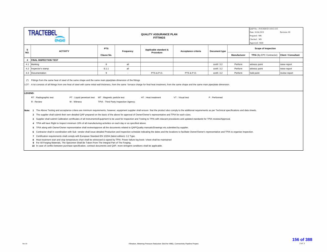
Date: 16.04.2019 Revision: 00
Prepared : MK
Checked : MS
Approved : SKH
PTS
Clause No. Manufacturer TPIA (By EPC Contractor) Client / ConsultantACTIVITY Frequency
QAP No. : P.013828 D 11013 215
Applicable standard &Procedure Acceptance criteria Document typeS
NO.
QUALITY ASSURANCE PLANFITTINGS
Scope of Inspection
4 FINAL INSPECTION TEST
4.1 Marking 8 all certif. 3.2 Perform witness point reiew report
4.2 8.1.1 all certif. 3.2 Perform witness point reiew report
4.3 Documentation 9 - PTS & P.O. PTS & P.O. certif. 3.2 Perform hold point review report
(*) Fittings from the same heat of steel of the same shape and the same main pipe/plate dimension of the fittings
LOT - A lot consists of all fittings from one heat of steel with same initial wall thickness, from the same furnace charge for final heat treatment, from the same shape and the same main pipe/plate dimension.
LEGEND:
RT : Radiographic test PT : Liquid penetrant test MT : Magnetic particle test HT : Heat treatment VT : Visual test P : Performed
R : Review W : Witness TPIA : Third Party Inspection Agency;
Note: 1
2 The supplier shall submit their own detailed QAP prepared on the basis of the above for approval of Owner/Owner's representative and TPIA for each sizes.
3
4
5
6
789
10
Contractor shall in coordination with Sub vendor shall issue detailed Production and Inspection schedule indicating the dates and the locations to facilitate Owner/Owner's representative and TPIA to organise Inspection.
Inspector's stamp
The Above Testing and acceptance critera are minimum requirements, however, equipment supplier shall ensure that the product also comply to the additional requirements as per Technical specifications and data sheets.
Supplier shall submit Calibration certificates of all Instruments/Equipment to be used for Inspection and Testing to TPIA with relavant procedures and updated standards for TPIA reveiew/Approval.
TPIA will have Right to Inspect minimum 10% of all manufacturing activities on each day or as specified above.
TPIA along with Owner/Owner representative shall review/approve all the documents related to QAP/Quality manuals/Drawings etc.submitted by supplier.
Certification requirements shall comply with European Standard EN 10204 (latest edition)- 3.2 Type.
In case of conflict between purchase specification, contract documents and QAP, more stringent conditions shall be applicable.
Heat treatment start and stop temperature chart shall be witnessed & signed by TPIA. Power failure log book / sheet shall be maintainedFor All Forging Materials, The Specimen Shall Be Taken From The Integral Part of The Forging.
Rev-00 Filtration, Metering Pressure Reduction Skid for HMEL Connectivity Pipeline Project. 3 of 3156 of 388

Revision: 00
VENDORTPIA(BY
EPC)
CLIENT /CONSULTANT
1
100% ASTM A 320 L7 / A 194 GR4/GR7 ASTM A 320 L7 / A 194 GR4/GR7 MTC 3.1 R W R
PER HEAT ASTM A 320 L7 / A 194 GR4/GR7 ASTM A 320 L7 / A 194 GR4/GR7 MTC / LAB TEST REPORT 3.1 R R RPER HEAT ASTM A 320 L7 / A 194 GR4/GR7 ASTM A 320 L7 / A 194 GR4/GR7 INSPECTION REPORT 3.1 R R R
100% ASTM A 320 L7 / A 194 GR4/GR7 ASTM A 320 L7 / A 194 GR4/GR7 INSPECTION REPORT 3.2 P W R
2
100% VENDOR DRG./ ASTM A 320 L7 / A 194 GR4/GR7/ASME B18.2.1&2.2
VENDOR DRG./ ASTM A 320 L7 / A 194GR4/GR7/ ASME B18.2.1&2.2 DIMENSION REPORT 3.1 P R R
100% VENDOR DRG./ ASTM A 320 L7 / A 194 GR4/GR7/ASME B18.2.1&2.2
VENDOR DRG./ ASTM A 320 L7 / A 194GR4/GR7/ ASME B18.2.1&2.2 DIMENSION REPORT 3.1 P R R
2. HEAT TREATMENT 100% ASTM A 370 / A 320 L7 / A194 GR4/GR7/SPECIFICATION.
ASTM A 370 / A 320 L7 / A194 GR4/GR7/SPECIFICATION.
HT GRAPH / INSPECTIONREPORT 3.1 P R R
3.STAMPING OF SAMPLE FORTESTING 100% ASTM A 370 / A 320 L7 / A194 GR4/GR7/
SPECIFICATION.ASTM A 370 / A 320 L7 / A194 GR4/GR7/
SPECIFICATION. INSPECTION REPORT 3.2 P W R
ONE / HEAT/LOT ASTM A 370 / A 320 L7 / A194 GR4/GR7/SPECIFICATION.
ASTM A 370 / A 320 L7 / A194 GR4/GR7/SPECIFICATION. INSPECTION REPORT 3.2 P W R
ONE / HEAT/LOT ASTM A 370 / A 320 L7 / A194 GR4/GR7/SPECIFICATION.
ASTM A 370 / A 320 L7 / A194 GR4/GR7/SPECIFICATION. INSPECTION REPORT 3.2 P W R
5 % / HEAT/LOT ASTM A 370 / A 320 L7 / A194 GR4/GR7/SPECIFICATION.
ASTM A 370 / A 320 L7 / A194 GR4/GR7/SPECIFICATION. INSPECTION REPORT 3.2 P W R
ONE / HEAT/LOT ASTM A 370 / A 320 L7 / A194 GR4/GR7/SPECIFICATION. AVG 27J & IND 20J / SPECIFICATION. INSPECTION REPORT 3.2 P W R
ONE / HEAT/LOT ASTM A 370 / A 320 L7 / A194 GR4/GR7/SPECIFICATION. A 320 L7 / A194 GR4 / GR7 / SPECIFICATION. INSPECTION REPORT 3.1 P R R
5 % / HEAT/LOT A 320 L7 / A194 GR4/GR7/ SPECIFICATION. A 320 L7 / A194 GR4 /GR7 / SPECIFICATION. INSPECTION REPORT 3.2 P W R
3
100% SPECIFICATION./ ASTM A 320 L7 / A194 GR4/GR7 SPECIFICATION./ ASTM A 320 L7 / A194GR4/GR7 INSPECTION REPORT 3.2 P 100% W R
100% APPRD. DRG./ ASTM A 320 L7 / A194 GR4/GR7 APPRD. DRG./ ASTM A 320 L7 / A194GR4/GR7 INSPECTION REPORT 3.2 P 10% W R
4
100% AS PER SPECIFICATION / AS PER APPR. DRG. &QAP
AS PER SPECIFICATION / AS PER APPR.DRG. & QAP COMPLIANCE CERTIFICATE P R R
100% AS PER SPECIFICATION / AS PER APPR. DRG. &QAP
AS PER SPECIFICATION / AS PER APPR.DRG. & QAP COMPLIANCE CERTIFICATE H P R
QUALITY ASSURANCE PLAN - FASTENERS
QAP No. : P.013828 D 11013 216
Date: 16.04.2019Prepared : MKChecked : MSApproved : SKH
SR. NO COMPONENTS & OPERATIONS TYPES OF CHECK
INSPECTION
RAW MATERIAL
QUANTUM OFCHECK REFERENCE DOCUMENTS ACCEPTANCE NORMS FORMAT OF RECORD
1. HEAT TREATMENT CYCLE (TEMP. / TIME CHART)
4. MECHANICAL TESTING3. HARDNESS TESTING
FINAL DOCUMENTS
FINAL INSPECTION
2. PROOF LOAD TEST
1. MFG. OF BOLT & NUT
INPROCESS INSPECTION.
1. CHEMICAL ANALYSIS
1. RAW MATERIAL
1. VISUAL INSPECTION, MARKING & CORRELATIONWITH MANUFACTURE TEST CERTIFICATE)
2. CHEMICAL COMPOSITION3. MECHANICAL PROPERTIES
1. FINAL DOCUMENTS
1.CUTTING , GRINDING, FORGING, THREADING ETC.
2. PRODUCT DIMENSIONS
4. PMI CHECK
1. VISUAL \ STAMPING \ MARKING \ COLOR CODING.
2. DIMENSIONS
2. PMI TEST
5. PRODUCT CHEMICAL CHECKANALYSIS
1. STAMPING OF TEST SAMPLE
1. TENSILE TESTING (TS,YS,EL%)
1. QAP / PO / MTC / IR / COMPLIANCECERTIFICATES
2. INSPECTION RELEASE NOTE
4. IMPACT TEST AT - 101° C
1.FINAL INSPECTION
Rev-00 Filtertion, Metering Pressure Reduction Skids for HMEL Connectivity Pipeline Project. Page 1 of 2157 of 388

Revision: 00
VENDORTPIA(BY
EPC)
CLIENT /CONSULTANT
QUALITY ASSURANCE PLAN - FASTENERS
QAP No. : P.013828 D 11013 216
Date: 16.04.2019Prepared : MKChecked : MSApproved : SKH
SR. NO COMPONENTS & OPERATIONS TYPES OF CHECK
INSPECTIONQUANTUM OF
CHECK REFERENCE DOCUMENTS ACCEPTANCE NORMS FORMAT OF RECORD
Legend:
NOTE :
5. IN CASE OF CONFLICT BETWEEN PURCHASE SPECIFICATION, CONTRACT DOCUMENTS AND QAP, MORE STRINGENT CONDITIONS SHALL BE APPLICABLE.4. SAMPLE FROM ANY ONE LOT/HEAT SHALL BE TESTED BY CLIENT UNDER THEIR WITNESS AT ANY NABL ACCREDITED LAB.
P-Perform, R-Review, W-Witness, H-Hold, IA - Inspection Agency (Purchaser / Owner's representative).
1. TPIA SHALL ISSUE 3.2 CERTIFICATE AS PER BS EN 102042. MATERIAL & TYPE SHALL BE AS PER SPECIFICATIONS / DATA SHEET3. START & STOP TEMP. CHART SHALL BE SIGNED BY TPIA, ALSO POWER FAILURE LOG SHALL BE MAINTAINED.
Rev-00 Filtertion, Metering Pressure Reduction Skids for HMEL Connectivity Pipeline Project. Page 2 of 2158 of 388

1
CHEMICAL TESTING 100% P R
PHYSICAL TESTING PER HEAT P R
FILLER MATERIAL-GRAPHITE CHEMICAL TESTING 100% AS PER APPLICABLE CODE OF
MAT./ ASME B 16.20AS PER APPLICABLE CODE OF
MAT/ ASME B 16.20 P R
CHEMICAL TESTING 100% MTC / LAB TESTREPORT 3.1 P R
PHYSICAL TESTING PER HEAT INSPECTIONREPORT 3.1 P R
2
FINISH DIMENSION FINISH DIMENSIONMEASURMENT OF SPW 100% APPR.VENDOR DRG./ ASTM A 240
/ ASME B16.20APPR.VENDOR DRG./ ASTM A 240 /
ASME B16.20DIMENSIONREPORT 3.1 P R
COMPRESSION &RECOVERY TESTING SPW ONE / SIZE / LOT ASTM A 370 / ASME B16.20 ASTM A 370 / ASME B16.20 INSPECTION
REPORT 3.1 P R
MARKING VISUAL 100% APPR.VENDOR DRG./ ASTM A 240/ ASME B16.20
APPR.VENDOR DRG./ ASTM A 240 /ASME B16.20
INSPECTIONREPORT 3.2 P W
VISUAL / TAGGING /MARKING 100% TENDER SPEC./ ASME B16.20 TENDER SPEC./ ASME B16.20 P 100% W
DIMENSIONS 100% APPRD. DRG./ ASTM A 240 / ASMEB16.20
APPRD. DRG./ ASTM A 240 / ASMEB16.20 P 100% W
QAP / PO / MTC / IR /COMPLIANCECERTIFICATES
100% P R
INSPECTION RELEASENOTE 100% H P
*
NOTE :
ACCEPTANCE NORMS
INPROCESS INSPECTION.
2. ABOVE ITP IS INDICATIVE ONLY. VENDOR SHALL SUBMIT DETAIL QAP FOR APPROVAL.
ASME B 16.20 / ASTM A 240 / TenderDoc.
ASME B 16.20 / ASTM A 240 / TenderDoc.
ASME B 16.20 / ASTM A 240 / TenderDoc.
ASME B 16.20 / ASTM A 240 / TenderDoc.
MTC / LAB TESTREPORT 3.1
AS PER TENDER SPEC / AS PERAPPR. DRG. & QAP
AS PER TENDER SPEC / AS PERAPPR. DRG. & QAP
INSPECTIONREPORT 3.2
COMPLIANCECERTIFICATE
SPIRAL WOUND GASKETWINDING MATERIAL- SS316/ SS316L
OUTER RING - CARBONSTEEL
A lot consists of all items from one heat of steel with same initial wall thickness, from the same furnace charge for final normalizing heat treatment, from the same shape and the same dimension.
Legend: P-Perform, R-Review, W-Witness, H-Hold, TPIA-Third Party Inspection Agency
SR. NO COMPONENTS &OPERATIONS TYPES OF CHECK
4 FINAL DOCUMENTS
3 FINAL INSPECTION
3. MATERIAL & TYPE SHALL BE AS PER TENDER SPECS/DATA SHEET.
INSPECTION & TEST PLANGASKET
FORMET OFRECORD
INSPECTION
VENDOR TPIA
RAW MATERIAL
QAP No. : P.013828 D 11013 217Date: 16.04.2019Prepared : MKChecked : SKApproved : SKH
1. Certification requirements shall comply with European Standard EN 10204 (latest edition)-3.2 issued by TPIA and Vendor.
QUANTAM OFCHECK REFERENCE DOCUMENTS
Rev. 00 Filtertion, Metering Pressure Reduction Skids for HMEL Connectivity Pipeline Project. Page 1 of 1
159 of 388
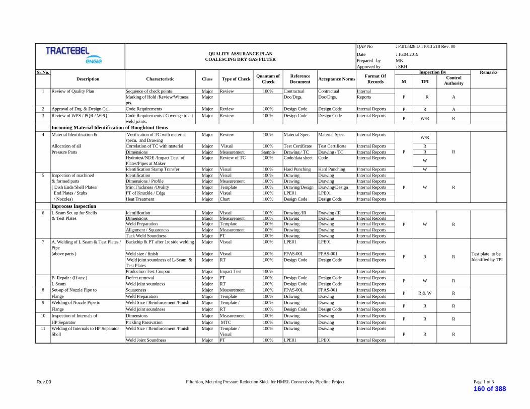
QAP No
DatePrepared by MKApproved by
Sr.No. Remarks
M TPIControl
Authority
1 Review of Quality Plan Sequence of check points Major Review 100% InternalMarking of Hold /Review/Witnesspts.
Major Reports
2 Approval of Drg. & Design Cal. Code Requirements Major Review 100% Design Code Design Code Internal Reports P R A3 Review of WPS / PQR / WPQ Code Requirements / Coverage to all
weld joints.Major Review 100% Design Code Design Code Internal Reports P W/R R
4 Material Identification & Verification of TC with materialspecn. and Drawing
Major Review 100% Material Spec. Material Spec. Internal Reports W/R
Allocation of all Correlation of TC with material Major Visual 100% Test Certificate Test Certificate Internal Reports RPressure Parts Dimensions Major Measurement Sample Drawing / TC Drawing / TC Internal Reports R
Hydrotest/NDE /Impact Test ofPlates/Pipes at Maker
Major Review of TC 100% Code/data sheet Code Internal Reports W
Identification Stamp Transfer Major Visual 100% Hard Punching Hard Punching Internal Reports W5 Inspection of machined Identification Major Visual 100% Drawing Drawing Internal Reports
& formed parts Dimensions / Profile Major Measurement 100% Drawing Drawing Internal Reports( Dish Ends/Shell Plates/ Min.Thickness /Ovality Major Template 100% Drawing/Design Drawing/Design Internal Reports End Plates / Stubs PT of Knuckle / Edge Major Visual 100% LPE01 LPE01 Internal Reports / Nozzles) Heat Treatment Major Chart 100% Design Code Design Code Internal Reports
6 L Seam Set up for Shells Identification Major Visual 100% Drawing /IR Drawing /IR Internal Reports& Test Plates Dimensions Major Measurement 100% Drawing Drawing Internal Reports
Weld Preparation Major Template 100% Drawing Drawing Internal ReportsAlignment / Squareness Major Measurement 100% Drawing Drawing Internal ReportsTack Weld Soundness Major PT 100% Drawing Drawing Internal Reports
7 A. Welding of L Seam & Test Plates /Pipe
Backchip & PT after 1st side welding Major Visual 100% LPE01 LPE01 Internal Reports
(above parts ) Weld size / finish Major Visual 100% FPAS-001 FPAS-001 Internal Reports Weld joint soundness of L-Seam &Test Plates
Major RT 100% Design Code Design Code Internal Reports
Production Test Coupon Major Impact Test 100% Internal ReportsB. Repair : (If any ) Defect removal Major PT 100% Design Code Design Code Internal ReportsL Seam Weld joint soundness Major RT 100% Design Code Design Code Internal Reports
8 Set-up of Nozzle Pipe to Squareness Major Measurement 100% FPAS-001 FPAS-001 Internal ReportsFlange Weld Preparation Major Template 100% Drawing Drawing Internal Reports
9 Welding of Nozzle Pipe to Weld Size / Reinforcement /Finish Major Template /Visual
100% Drawing Drawing Internal ReportsFlange Weld joint soundness Major RT 100% Design Code Design Code Internal Reports
10 Inspection of Internals of Dimensions Major Measurement 100% Drawing Drawing Internal ReportsHP Separator Pickling Passivation Major MTC 100% Drawing Drawing Internal Reports
11 Welding of Internals to HP SeparatorShell
Weld Size / Reinforcement /Finish Major Template /Visual
100% Drawing Drawing Internal Reports
Weld Joint Soundness Major PT 100% LPE01 LPE01 Internal Reports
QUALITY ASSURANCE PLANCOALESCING DRY GAS FILTER
: P.013828 D 11013 218 Rev. 00
: 16.04.2019
: SKH
ReferenceDocumentDescription Characteristic Class Type of Check
Inspection By
R
R
R
P R
W
R R
W
R & W
R
Inprocess Inspection
ContractualDoc/Drgs.
ContractualDoc/Drgs.
P
P
P
P
P
P
A
Test plate to beIdentified by TPI
R
R
RW
P R
R
P R
R
Quantam ofCheck
Format OfRecordsAcceptance Norms
Incoming Material Identification of Boughtout Items
P
Rev.00 Filtertion, Metering Pressure Reduction Skids for HMEL Connectivity Pipeline Project. Page 1 of 3
160 of 388

QAP No
DatePrepared by MKApproved by
Sr.No. Remarks
M TPIControl
Authority
QUALITY ASSURANCE PLANCOALESCING DRY GAS FILTER
: P.013828 D 11013 218 Rev. 00
: 16.04.2019
: SKH
ReferenceDocumentDescription Characteristic Class Type of Check
Inspection ByQuantam of
CheckFormat Of
RecordsAcceptance Norms
12 C Seam Set up for Shells Identification Major Visual 100% Drawing /IR Drawing /IR Internal Reportsto Dish Ends & Test Dimensions Major Measurement 100% Drawing Drawing Internal ReportsPlates Weld Preparation Major Template 100% Drawing Drawing Internal Reports
Alignment / Squareness Major Measurement 100% Drg./FPAS001 Drg./FPAS001 Internal ReportsTack Weld Soundness Major PT 100% Drawing Drawing Internal Reports
13 A. Welding of C Seam Backchip & PT after 1st side(above parts ) & Test weldingPlates Weld size / finish Major Visual 100% FPAS-001 FPAS-001 Internal Reports
Weld joint soundness of C-Seam Major RT 100% Design Code Design Code Internal ReportsB. Repair : (If any ) - Defect removal Major PT 100% Design Code Design Code Internal ReportsC Seam - Weld joint soundness Major RT 100% Design Code Design Code Internal Reports
14 Heat Treatment of Test - Time / Temperature Charts Major Visual 100% Design Code Design Code Internal ReportsPlates + EQPT As Per Code Internal Reports
15 Testing of All Test Plates - Mechanical / Physical Test Major Visual 100% Design Code Design Code Internal Reports Reports Internal Reports
16 Inspection of Marking for - Identification Major Visual 100% IR/ Drawing IR/ Drawing Internal ReportsOpenings on Dish End - Layout Major Measurement 100% Drawing Drawing Internal Reports/ Shell - Orientation Major Visual 100% Drawing Drawing Internal Reports
- Dimensions Major Measurement 100% Drawing Drawing Internal Reports- No. of holes Major Count 100% Drawing Internal Reports
17 Inspection after opening A- Earlier stage clearance review Major Review 100% Acc.Inspn.Rep. Acc.Inspn.Rep. Internal Reportson Shell/ Dish End B- Opened holes orientation Visual 100% Drawing Drawing
QuadrantwiseH- Hole finish Major Visual 100% FPAS001 FPAS001 Internal ReportsI- Final Acceptance Major Visual 100% Hard Stamping of
Insp.Hard Stamping ofInsp.
Internal Reports
18 Setup of studs,nozzles, Orientation Major Visual 100% Drawing Drawing Internal Reportssockets Weld preparation Major Template 100% Drawing/Code Drawing/Code Internal Reports& connections with Alignment Major Line Thread 100% Drg/FPAS001 Drg/FPAS001 Internal ReportsShell / Dish End / Flange Squareness Major Right Angle 100% Drg/FPAS001 Drg/FPAS001 Internal Reports
Distance between connections Major Measurement 100% Drg/FPAS001 Drg/FPAS001 Internal ReportsTack weld soundness Major PT 100% LPE01 LPE01 Internal Reports
19 Welding of Nozzles, Weld size/ finish Major Visual 100% Design Code Design Code Internal Reports& connections to Shell/DE Weld Soundness Major RT/ PT 100% Design Code Design Code Internal Reports
20 Set up of of Structurals Dimensions Major Measurement 100% Drawing Drawing Internal Reports PSaddles & Attachments Weld Preparation Major Template 100% Drawing Drawing Internal Reports
Alignment / Squareness Major Measurement 100% Drg/FPAS001 Drg/FPAS001 Internal Reports21 Welding of Structurals Weld size / finish Major Visual 100% Design Code Design Code Internal Reports
Saddles & Attachments Weld soundness Major PT Sample Design Code Design Code Internal Reports P
W/R
Repair RT to beReviewed by
TPIA
W
R
R
R
P
P
P R
P
P
P
R
W/R
W
R R
R
R
RW(RandomWitness)
P
R
R
P
Test Plate To BeImpact Tested &
Shall BeWitnessed By
TPIA
-- Do --
W/R
R
100%
P RW
Major
-NA-
LPE01
W/RR
VisualMajor
Internal Reports
Internal ReportsLPE01
Rev.00 Filtertion, Metering Pressure Reduction Skids for HMEL Connectivity Pipeline Project. Page 2 of 3
161 of 388

QAP No
DatePrepared by MKApproved by
Sr.No. Remarks
M TPIControl
Authority
QUALITY ASSURANCE PLANCOALESCING DRY GAS FILTER
: P.013828 D 11013 218 Rev. 00
: 16.04.2019
: SKH
ReferenceDocumentDescription Characteristic Class Type of Check
Inspection ByQuantam of
CheckFormat Of
RecordsAcceptance Norms
22 Full Welding clearance Overall Dimensions Major Measurement 100% Drawing Drawing Internal ReportsSquareness of Connections Major Measurement 100% Drawing Drawing Internal ReportsDistance between Connections Major Measurement 100% Drawing Drawing Internal ReportsRT Clearance / U.T. Major Review of RT 100% Drawing Drawing Internal Reports
Rpts. Internal ReportsCode Punching Details Major Ruboff 100% Design Code Design Code Internal Reports
Final Inspection Internal Reports23 Hydrostatic Testing Pressure gauge(2 no) Major Review 100% Valid Cert. Valid Cert. Internal Reports
Calibration Major Visual 100% No leakage No leakage Internal ReportsLeakages Major 100% Internal Reports
24 Final Inspection Document Review Major Review 100% Design Code Design Code Internal ReportsDimensions Major Measurement 100% Drawing Drawing Internal ReportsSurface Preparation Major Visual 100% Free from scales
etc.Free from scalesetc.
Internal Reports
25 Painting finish Major Visual 100% Drawing Drawing Internal Reports
Capping / Blanking of all opening Major Visual 100% All openingprotected
All openingprotected
Internal Reports
Code Punching details Major Visual 100% Design Code Design Code Internal Reports
M PNA RC W
TPI W/RA H
CA RW
ReviewNot ApplicableClient - GSPL
W
P
Clearance for Assembly / Despatch ( AsApplicable )
W/RP
P
P
W/R
W/R
Third Party Inspection AgencyFor Approval
Legend
Note: Vendor to furnish 3.2 Certification for filter .
Manufacturer Perform
W/R
R
W
W
Control Authority Random Witness
WitnessWitness of Test & Review of Certificates & Documents as per QAPHold
Rev.00 Filtertion, Metering Pressure Reduction Skids for HMEL Connectivity Pipeline Project. Page 3 of 3
162 of 388

PTS – FILTRATION & METERINGSKID
P.013828D 11077
606
HMEL CONNECTIVITY PIPELINE PROJECT, BHATINDA
TRACTEBEL ENGINEERING PVT. LTD.
PTS – FILTRATION & METERING SKID
00 18.04.19 Issue for RFP KJ SHD SKH
Rev. Date Subject of revision Author Checked Approved
163 of 388

PTS – FILTRATION & METERINGSKID
P.013828D 11077
606
Rev.00 HMEL Connectivity Pipeline Project Page 2 of 5
TABLE OF CONTENTS
1. SCOPE ....................................................................................................................................... 1
2. GENERAL................................................................................................................................... 1
3. DESIGN DATA (ENVIRONMENTAL CONDITION) ................................................................ 2
4. DESCRIPTION OF THE SUPPLY ............................................................................................. 2
5. LIMITS OF SCOPE .................................................................................................................... 4
6. LIMIT OF SUPPLY (BATTERY LIMIT) .................................................................................... 4
7. GENERAL DESCRIPTION ........................................................................................................ 4
8. PIPING REQUIREMENTS ........................................................................................................ 5
9. INSTRUMENT IDENTIFICATION ........................................................................................... 5
10.LABELLING REQUIREMENTS ................................................................................................. 5
164 of 388

PTS – FILTRATION & METERINGSKID
P.013828D 11077
606
Rev.00 Filtration, Metering & Pressure Reduction Skids for Pipeline Projects Page 1 of 5
1. SCOPEThis particular technical specification covers the minimum requirements for the engineering, fabrication,testing, calibration and supply of Filtration and metering skids.
2. GENERAL
2.1. Definitions
Subject to the requirements of the context, the terms (hereafter listed in alphabetical order) used in thisspecification are given the following meaning:
AGREEMENT Designates the agreement concluded between the OWNER and theCONTRACTOR, under which the latter undertakes to the former theGOODS and/or SERVICES according to the stipulations which areagreed and specified in the form of an order
OWNER Designates the purchaser of the GOODS and/or SERVICES whichare the subject of the AGREEMENT.
CONTRACTOR Designates the individual or legal entity with whom the order hasbeen concluded by the OWNER. The term "CONTRACTOR" maybe used indifferently for a supplier, a manufacturer, an erectioncontractor, etc.
DAYS - WEEKS – MONTHS Specify the number of calendar days, weeks or months and not ofworking days, weeks or months.
OWNER’S ENGINEER Designates TRACTEBEL Engineers Pvt. Ltd. and its associates, ifany, to which the OWNER has entrusted various tasks in relationwith the carrying out of his PROJECT.
GOODS and or SERVICES Designate, depending on the case, all or part of the drawings ordocuments, substances, materials, equipment, structures, plant, tools,machinery, ... to be studied , designed, manufactured, supplied,erected, built, assembled, adapted, arranged or put into service bythe CONTRACTOR under the agreement, including all the studies,tasks, works and services specified by the order. The terms GOODSor SERVICES may by indifferently used one for the other asrequired by the context.
PROJECT Designates the aggregate of GOODS and/or SERVICES to beprovided by one or more CONTRACTORS.
2.2. Applicable Technical Specifications
The design, construction, materials, testing shall be in accordance with all the Particular TechnicalSpecifications (PTS) and General Technical Specification (GTS) applicable to the project as follows:
PTS- Filtration and Metering Skid
PTS- Pressure Reduction Skid
PTS - Instrumentation for Package Units.
70000/734/xx/7001 – Name plates & Tags for instrumentation
70000/740/GTS/402 – Pipeline Valves
GTS 734/003 - Instrumentation Symbols and Identification.
165 of 388

PTS – FILTRATION & METERINGSKID
P.013828D 11077
606
Rev.00 Filtration, Metering & Pressure Reduction Skids for Pipeline Projects Page 2 of 5
GTS/734/013 – Instrumentation for package unit
70000/734/GTS/040 – Gas Heating and Pressure Let-down Skid – Boiler Skid
70000/740/GTS/006 - Filtration Skid (coalescing type filter) for Metering Station.
70000/740/GTS/0023 - Natural Gas Metering Station with Ultrasonic Flow Meters.
J/02/3009 – Instrumentation Erection
In case of contradiction document precedence shall be as follows:
P&ID,
MR,
Data Sheets,
PTS,
QAP,
GTS,
Codes & Standards.
2.3. Codes, Standard and Legal Requirements
The design, construction, materials, testing of metering, filtration skid shall be in accordance with theInternational codes and standards, European codes and standards and legal requirements mentioned in thepresent specification and in other Technical Specifications (GTS and PTS) applicable to the PROJECT.
2.4. Review and/or Approval
Whenever OWNER and/or OWNER’S ENGINEER review and/or approval is requested on a document tobe submitted by the CONTRACTOR or before an action is implemented by the CONTRACTOR, suchreview and/or approval shall always be requested in writing by the CONTRACTOR to the OWNER and/orthe OWNER’S ENGINEER before any action subject of this review and/or approval is taken.
OWNER and/or OWNER’S ENGINEER approval shall always be given in writing.
3. DESIGN DATA (ENVIRONMENTAL CONDITION)
3.1. Gas Composition
The gas composition, to be considered for the design of the new metering station, is given in PTS –Instrumentation Package Unit.
3.2. Operating Conditions
The operating conditions of the metering stations are given in PTS –Instrumentation Package Unit.
4. DESCRIPTION OF THE SUPPLY
CONTRACTOR shall considered and offered for the following skid :
4.1. FILTRATION SKID
166 of 388

PTS – FILTRATION & METERINGSKID
P.013828D 11077
606
Rev.00 Filtration, Metering & Pressure Reduction Skids for Pipeline Projects Page 3 of 5
4.1.1. Filtration skid comprising of all the material required for removing the solid and liquid particles larger than3 micron from the gas.
4.1.2. The filter shall be of the Single chamber coalescing type.
4.1.3. The supply shall include all the required material (Filter, piping, valves, safety devices, instruments, andwiring) inside the battery limits of the skid, as shown in the P&ID and mentioned in MR and PTS.
4.1.4. The minimum requirements for the filtering skid are covered by the general technical specification70000/740/GTS/006 "Filtration skid (coalescing type filter)".
4.2. METERING SKID
4.2.1. Metering skid comprising all the material required for gas flow rate.
4.2.2. The supply shall include all the required material for measurement (flow meters USM type, flow computer,related valves, piping, safety devices, instruments, wiring etc) along with bypass arrangement (Spool forfuture with valve assembly) inside the battery limits of the skid as shown on the typical P&ID and asmentioned in MR and PTS.
4.2.3. The maximum permitted velocity through USM shall be 20 meter/ sec.
4.2.4. The minimum requirements for the metering skids are covered by the same general technical specificationsGTS- 70000 /740/ GTS/ 0023.
4.3. OTHER SUPPLIES
The following supplies shall be included in Contractor bid:
The shop painting in accordance with paint system specification.
Spare parts for mandatory spares as per List of Mandatory.
The engineering documents requested in the DDR attached to the Material Requisition.
The material certificates, Ex certificates.
Supply of erection hardware, cables & accessories, etc.
Skid structure and platforms.
4.4. SERVICES
The contractor shall include in his bid the following services:
The complete engineering / design of the skids.
The mechanical tests.
The non-destructive tests.
The performance tests.
The assistance for Supervision of Erection, Testing, pre-commissioning, commissioning and start-up
The services of a Control Authority for the delivery of 3.1/ 3.2 certificate as per attached QC/QAsheets.
TPI for all supplies
Thermal insulation (If required).
167 of 388

PTS – FILTRATION & METERINGSKID
P.013828D 11077
606
Rev.00 Filtration, Metering & Pressure Reduction Skids for Pipeline Projects Page 4 of 5
5. LIMITS OF SCOPE
The scope of the CONTRACTOR includes:
Detailed drawings and calculations.
Co-ordination with third party inspection agency.
Design, fabrication, assembly, testing, installation, testing & commissioning of the complete.
Junction boxes for connection to the field instruments with FC (different junction boxes shall beprovided for analogue signals, digital signals, power supplies, etc.);
mandatory spares;
mechanical tests;
material certificates;
non destructive tests;
performance tests;
Preparation and application of shop painting;
FAT of the skids;
SAT of the skids.
6. LIMIT OF SUPPLY (Battery limit)
6.1. Piping
The battery limit connections shall be as per P&IDs.
6.2. Instrumentation
Junction boxes for connections to control panel / cabinet / FC signals shall be separated as follows :
Analogue signal
Digital signal
All type of signal cable & control cable from skid JB to Flow computer (located in control room).
7. GENERAL DESCRIPTION
7.1. The supply of the metering skids shall cover as a minimum the design, manufacture, assembly, calibration,testing and commissioning of the skid and safety associated devices. The package shall also include all thenecessary control equipment with enclosures suitable for the working environment.
7.2. The straight length of calibrated pipe forming the upstream and downstream parts of the meter tubes shallbe cut from one piece of pipe without any intermediate girth weld.
7.3. The meter shall be wet calibrated (at the average metering pressure) as per operating conditions along withits upstream and downstream meter runs and profiler. The upstream & downstream meter runs shall behoned and the maximum meter tube roughness should not exceed 300 micro-inches.
7.4. All meter run pipes shall be specially selected for dimensional accuracy and shall be free from allimperfections and corrosion on internal surfaces. Meter runs shall be chosen according to applicablegeometric requirements of AGA 9 for Ultrasonic type metering skid.
7.5. The calibrated meter runs shall be easily removable and shall be connected to an adjacent piping by means
168 of 388

PTS – FILTRATION & METERINGSKID
P.013828D 11077
606
Rev.00 Filtration, Metering & Pressure Reduction Skids for Pipeline Projects Page 5 of 5
of flanges.
7.6. The Ultrasonic meter shall be installed in a region of zero stress in the pipeline to minimize strain on themeter. The upstream pipe work shall be carefully aligned to minimize flow disturbances, especially at theupstream flange of the meter.
7.7. The Filtration, pressure reduction system / flow control system shall be designed to minimize the generationof ultrasonic noise in the frequency range of Ultrasonic meter. Also, the pressure reduction system, meteringsystem and flow control system should be separated with blocking tees / other piping lay-outs, so that theUltrasonic noise generated through various components of skid does not affect Ultra Sonic Meterperformance. (The requirement and design of blocking Tees / Double Tees or any other piping layout is tobe decided by vendor and shall be approved by the original meter manufacturer.)
7.8. Lifting lugs and their supporting structure and spreader bar (one for each skid) shall be designed for a loadequal to two times the weight to be lifted (shipping weight).
7.9. Supplier shall note that the complete skid to be pneumatically tested in the factory premises @ 7.0 Bargwith N2/Air. In case of dismantling of the skid due to transportation, same shall be re-tested once again atthe installation SITE @ 7.0 Barg with N2/Air.
7.10. The Check meter skid equipment at field like transmitters (pressure & temperature) shall be installed in anenvironmental enclosure to minimize the effects of ambient temperature variations and shall be lockable forprevention of unauthorized data entry. The size of the cabinet shall be suitable for removing and fixing oftransmitters for ease of maintenance. The transmitters shall be fixed in mounting brackets inside the cabinet.The cabinet shall be mounted and fixed in the skid.
7.11. Contractor shall submit meter including piping duly approved by NMI/ PTB/ NPL or equivalent for custodytransfer application and shall be strictly as per the guidelines of AGA 9. The total uncertainty calculation ofthe metering system to be submitted as per the design data prior to the fabrication of skid. Criticalcomponents within the custody transfer metering system should be compatible to ensure “Overall SystemUncertainty” for this critical fiscal transaction purpose with all components within the metering system mustbe well proven and compatible in the similar application.
7.12. The design of the Profiler (for USM) shall be as per AGA. The wet calibration/ proving of the meter shall beas per situ condition. For USM, the wet calibration shall be done along with up-stream, downstream meterrun and flow profiler. Flow profiler shall be 316 stainless steel of between-flanges. These shall comply withthe requirements of AGA 9 for ultrasonic meters. Where flow profilers are recommended, care must betaken to select flow profilers that do not generate acoustic noise with harmonic frequencies that mayinterfere with the USM performance.
8. PIPING REQUIREMENTS
All the piping part of the package shall be in accordance with the piping classes given in the project relevantPTS.
9. INSTRUMENT IDENTIFICATION
Instrument symbols and identification on P&I Diagrams shall be in accordance with the specificationGTS/734/003 "Instrumentation symbols and identification".
10. LABELLING REQUIREMENTS
Refer to the relevant general technical specifications (GTS)
169 of 388
PTS - PRESSURE LETDOWN SKIDP.013828D 11077
607
00 18.04.19 Issue for RFP KJ SHD SKH
Rev. Date Subject of revision Author Checked Approved
HMEL CONNECTIVITY PIPELINE PROJECT, BHATINDA
TRACTEBEL ENGINEERING PVT. LTD.
PTS - PRESSURE LETDOWN SKID
170 of 388

PTS - PRESSURE LET DOWN SKID
P.013828D 11077
607
Rev.00 HMEL Connectivity Pipeline Project Page 2 of 5
TABLE OF CONTENTS
1. SCOPE ........................................................................................................................................3
2. DESCRIPTION OF THE SUPPLY ..............................................................................................3
3. APPLICABLE CODES, STANDARDS AND SPECIFICATIONS ...............................................4
4. ELECTRICAL REQUIREMENTS ................................................................................................5
5. PIPING REQUIREMENTS .........................................................................................................5
6. UTILITIES ..................................................................................................................................5
171 of 388

PTS - PRESSURE LET DOWN SKID
P.013828D 11077
607
Rev.00 HMEL Connectivity Pipeline Project Page 3 of 5
1. SCOPE
1.1 The supply shall cover as a minimum the design, manufacture, assembly, test and supply of the gas pressurereduction skids TWO STREAM (2 x 100%) with provision of one stream of same capacity in future withself-actuated active & monitor pressure regulator and SSV at Receiving terminal at HMEL and safetyassociated devices. The packages shall also include all the necessary control equipment with enclosuressuitable for the working environment. Information from the skids shall be transmitted by hardwiring toMetering cabinet.
2. DESCRIPTION OF THE SUPPLY
2.1. Pressure Reduction Skids at Receiving terminal at HMEL:The design, fabrication, supply, calibration, testing and commissioning shall include all the materialrequired, inside the battery limits of the skids, as shown on the attached “P&ID of a Pressure reductionSkid".
For details of the instruments, refer PTS-Instrumentation Package unit.
The minimum requirements for the pressure let down/reduction skids are covered by the general technicalspecification 70000/734/GTS/040 "Gas heating & pressure letdown skid - Boiler skid".
2.2. Self-actuated pressure regulated valves and slam shut valves:
2.2.1. Set point of the Gas pressure regulators/ Monitor (PRVs) and Slam Shut Valves (SSVs) shall be adjustable.Vendor shall furnish the adjustable range of the Gas pressure regulators/monitors and slam shut valves. SSVshall have position indicators (Open & Close) for monitoring the position.
2.2.2. Each pressure regulator / monitor shall be designed for maximum gas flow rate at the minimum inlet arrivalpressure.
2.2.3. Pressure regulators/ monitors shall be self actuated pilot operated with regulation accuracy of better than +/-1% of set point.
2.2.4. The construction of the Regulators / monitors shall be such that there will be no continuous gas bleeding.
2.2.5. Leakage class for pressure control valve & slum-shut valve shall be class-VI as per ANSI B16.104
2.2.6. Vendor to note that the noise level for each Regulator / monitor valve shall be less than 85 dBA at onemeter away from the valves. Vendor shall provide noise treatment to limit the noise level and includesilencers or expanders as required in their scope of supply. Vendor to provide Noise calculation giving fulldetails and standards used and any assumptions considered in calculation. Slam shut valve shall be self-contained type requiring external control line such that the line pressure acts directly on the diaphragm.
2.2.7. Closing time of slam shut valve shall be less than 2 seconds for all sizes of the valves. Actual closing timeof the valve shall be furnished by vendor with the quotation.
2.2.8. Slam shut valves shall be provided with position indicator and shall have separate limit switches for openand close positions. Limit switches shall be with DPDT, snap acting micro switch with contact rating 1 A @24 V DC. Limit switch enclosure shall be weather proof to IP 65 and flame proof (Exd) suitable andcertified for area classification IEC Zone 1, Gr. IIA, IIB, and T6. Cable entry shall be ½” NPT withoutflying leads.
2.2.9. Resetting of slam shut valves shall be only manual.
172 of 388

PTS - PRESSURE LET DOWN SKID
P.013828D 11077
607
Rev.00 HMEL Connectivity Pipeline Project Page 4 of 5
2.2.10. The automatic switchover shall be achieved with appropriate staggered setting of Pressure regulator/monitorand slam shut valves. Vendor shall select the appropriate set points such that the switch-over is smoothwithout affecting the safety of the system and gas supply to consumers is also not interrupted.
2.2.11. Slam shut valves shall be provided to indicate valve open or close position to Metering Cabinet & MeteringCabinet interface with RTU.
2.2.12. Slam shut valve shall have a set point accuracy of ±1% over the whole operating range.
2.2.13. The complete station shall be designed in such a way that the mean gas velocity remains within 20 Meterper second except in Pressure regulating valve / slam shut valve. Velocity in the piping upstream /downstream of Pressure reduction station shall be within 20 Meter per second. Maximum seat velocity ofSlam shut valves is limited to 40 meter / second.
2.2.14. The SSV shall be designed in such a way the noise generated by these equipments shall not interfere withthe performance of the meter.
2.2.15. The self actuating Pressure regulating valve shall be designed as per EN334 and Pressure EquipmentDirective PED 97/23/EC covering the production quality assurance.
2.2.16. The Slam shut valve shall be designed as per EN14382 and Pressure Equipment Directive PED 97/23/ECcovering the production quality assurance
2.3. Other Supplies
The following supplies shall be included in Vendor bid:The shop painting in accordance with paint system specification.Mandatory spares as per list.The engineering documents requested in the DDR attached to the Material Requisition.The material certificates.Skid structure and platforms.
2.4. Services
The vendor shall include in his bid the following services:
The complete engineering / design of the skids.The mechanical tests.The non destructive tests.The performance tests.The assistance / supervision of the erection.The assistance for commissioning and start-up.Testing, pre-commissioning, commissioning and start up.The services of a control authority for the delivery of 3.2 certificates as per QC/QATPI for all supplies.
3. APPLICABLE CODES, STANDARDS AND SPECIFICATIONS
The design, materials, construction and testing of the skids shall be in accordance with the applicableinternational codes, standards and legal requirements and with the project Technical Specifications as listedhereunder.
INTERNATIONAL CODES, STANDARDS AND LEGAL REQUIREMENTS
173 of 388

PTS - PRESSURE LET DOWN SKID
P.013828D 11077
607
Rev.00 HMEL Connectivity Pipeline Project Page 5 of 5
European Standards:
EN 12186 Gas supply systems - Gas Pressure Regulating Stations for Transmission andDistribution - Functional requirements
3.2 Certification Shall have the meaning as provided by EN 10204 Code and summarized asfollow: “The manufacturer’s authorized inspection representative independentof the manufacturing department and either the purchaser’s authorizedinspection representative or the inspector designated by the officialregulations.”
TRACTEBEL ENGINEERING GENERAL TECHNICAL SPECIFICATIONS:
PTS -Instrumentation for Package Units.
GTS 734/003 - Instrumentation Symbols and Identification.
70000/734/GTS/040 - Gas Heating & Pressure Letdown Skid - Boiler Skid.
In case of contradiction document precedence shall be as follows:
P&ID,
MR,
Data Sheets,
PTS,
QAP,
GTS,
Codes & Standards.
4. ELECTRICAL REQUIREMENTS
Electrical materials will in general follow the IEC standards and be in compliance with all applicable localregulations.
As per IEC, the material will be installed in hazardous area zone 1 and classified as EEx-d IIA/IIB, T6.Enclosure protection degree as per min. IP65.
5. PIPING REQUIREMENTS
All piping and valves shall be in accordance with the piping classes attached to the Material Requisition.
6. UTILITIES
6.1 Consumptions
The Contactor shall indicate the expected utilities consumption; ie electrical power, gas (for SSV, monitor& regulator valve) whichever applicable. The contractor shall propose a guarantee value for both.
174 of 388
PTS – INSTRUMENTATION PACKAGEUNIT WITH APPENDICES
P.013828D-11077
608
HMEL CONNECTIVITY PIPELINE PROJECT, BHATINDA
TRACTEBEL ENGINEERING PVT. LTD.
PTS - INSTRUMENTATION PACKAGE UNIT WITH APPENDICES
00 18.04.19 Issued for RFP KJ SHD SKH
Rev. Date Subject of revision Author Checked Approved
175 of 388

PTS – INSTRUMENTATION PACKAGEUNIT WITH APPENDICES
P.013828D-11077
608
Rev.00 HMEL Connectivity Pipeline Project Page 2 of 24
TABLE OF CONTENTS
1.0 INTRODUCTION ................................................................................................................. 3
2.0 INSTRUMENT IDENTIFICATION ..................................................................................... 3
3.0 DESIGN PRINCIPLES ........................................................................................................ 3
4.0 ENGINEERING AND DESIGN DOCUMENTS & DRAWINGS .......................................... 5
5.0 GENERAL DISCRIPTION FOR SUPPLY AND DESIGN CONSIDERATION .................... 7
6.0 PANEL/CABINET CONFIGURATION ................................................................................ 8
7.0 PANEL WIRING ................................................................................................................ 10
8.0 FLOW METER (ULTRASONIC TYPE) .............................................................................. 11
9.0 FLOW COMPUTER ............................................................................................................ 12
10.0 INSTRUMENT INSTALLATION ....................................................................................... 15
11.0 INSTRUMENTATION WIRING........................................................................................ 16
12.0 CALIBRATION AND SYSTEM TESTING ......................................................................... 18
13.0 INSTRUMENT CABLES ..................................................................................................... 20
176 of 388

PTS – INSTRUMENTATION PACKAGEUNIT WITH APPENDICES
P.013828D-11077
608
Rev.00 HMEL Connectivity Pipeline Project Page 3 of 24
1.0 INTRODUCTION
This specification covers the basic requirements for the design, the selection, the requisitioning and theinstallation of instrumentation and control systems associated with equipment purchased as a "Package Unit".
2.0 INSTRUMENT IDENTIFICATION
Each instrument shall be identified by unique tag no. as per P&ID.
3.0 DESIGN PRINCIPLES
3.1 General
Instrumentation, control and monitoring systems of Package units shall be in accordance with this specificationand as defined in the P&I Diagrams.
The Package Units shall be supplied complete with all instrumentation, fully piped, wired and tested to ensuresafe, reliable and effective operation as well as easy maintenance of the complete Package Units.
Protection and packing of all materials shall be suitable for shipment and protection on jobsite during storageprior to erection.
3.2 Instrument Selection
Instruments and instrumentation systems of proven reliability shall be used.
Selection of instrumentation shall be made from the approved Instrument Supplier Lists.
Any exception has to be justified and is subject to approval by the Owner/Owner’s Engineer.
3.3 Tagging
All instruments and instrumentation equipment shall be permanently identified by tags, labels and/ornameplates. Use of adhesive tapes shall not be allowed.
3.4 Painting
Manufacturer's standard colours shall be used for all instrumentation equipment in control and instrumentrooms, unless otherwise specified.
Field instruments shall generally be epoxy painted, unless otherwise specified.
3.5 Transmission Systems
1) Transmission of the process variables shall generally be by means of electronic or low level signals.
2) The output signal for electronic instruments shall be 4 to 20 mA DC or digital.
3) As far as possible, a true two-wire transmission system shall be used.
4) Each pneumatic instrument shall be provided with its own air/gas filter regulator.
5) No process fluid shall be piped into the control rooms or the instrument rooms.
3.6 Enclosures and Materials
177 of 388

PTS – INSTRUMENTATION PACKAGEUNIT WITH APPENDICES
P.013828D-11077
608
Rev.00 HMEL Connectivity Pipeline Project Page 4 of 24
1) All instruments shall be suitable to withstand the environmental conditions specified for the plant location.
2) All parts subject to moisture, fungus growth or insect attack shall be suitably treated (tropicalisation).
3) Local instruments/ equipments housing shall be weather-proof (WP to IP65 minimum) and shall meet theelectrical area classification requirements.
a. Control / Electronics Room mounted instruments/equipments housing shall be Ingress Protection IP-42minimum and shall meet the electrical area classification requirements.
4) All parts of instruments exposed to process fluids shall be resistant to corrosion by the corresponding fluid.
3.7 Electronic Instrumentation in Hazardous Areas
1) In hazardous areas, intrinsically safe instrumentation shall be provided.
2) If not possible or not practical, flameproof concept may be applicable.
3) All electrical instruments to be installed in hazardous locations shall be certified to ATEX directives orother international agencies like CSA, UL, and FM.
4) Contacts shall be encapsulated and, if used in intrinsically safe circuits, contacts shall be gold plated.
3.8 R.F. Immunity
All instruments and control systems shall be immune from the effects of any R.F. interference that may occur atthe plant location in accordance with IEC 801 "Electromagnetic compatibility for industrial-processmeasurement and control equipment".
3.9 Electrical Power Supply
Non UPS and UPS power supply 230 V AC +/- 10%, 50 Hz+/- 5% shall be available. If other voltage levels arerequired, the same shall be in the scope of contractor.
3.10 Instrument Connections
1) In general, process connections on instruments shall be 1/2" NPT.
2) Pneumatic connections shall generally be 1/2". Larger sizes may be used for special applications, e.g. forhigh-speed actuators.
3) Electrical connections on field instruments shall be ½” NPT.
3.11 Measuring Units
The metric SI system shall be used for all documents. The following units of measurement as well as theirmultiples and sub-multiples, shall be used:
3.11.1 Flow
Gas : Sm3/h (15.556OC; 1.01325 bara), MSCMD
Liquid : m3/h (at flowing temperature)
L/h for flow lower than 0.1 m3/h
178 of 388

PTS – INSTRUMENTATION PACKAGEUNIT WITH APPENDICES
P.013828D-11077
608
Rev.00 HMEL Connectivity Pipeline Project Page 5 of 24
Steam, condensate and mass flow: kg/h.
3.11.2 Pressure
Gauge pressure : kg/cm2 (g) and Bar (g)
Absolute pressure : kg/cm2 (a) and Bar (a)
Differential pressure : kg/cm2, mm of H2O, mm of Hg and mill bar
3.11.3 Level
0 - 100 % (Process)
3.11.4 Temperature
Deg C
3.11.5 Other Measurements
Current: A or mA
Voltage: V or mV
Power: kW
Force: N
Mass: kg or t
Density: kg/m3
Time: d or h or s.
3.12 Scales and Charts
1) Temperature instruments shall have scales calibrated in °C.
2) Pressure instruments shall have scales calibrated in bar g.
3) Absolute pressure instruments shall have scales calibrated in bar g (a).
4) Flow instruments shall have either 0 - 10 square roots (local instruments) or 0 – 100 linear scales (controlroom instruments).Scale multipliers shall be based on the measurement units defined.
5) Level instruments shall have scales calibrated 0 - 100 %.
6) Charts for all instruments shall be 0 - 100 linear.
4.0 ENGINEERING AND DESIGN DOCUMENTS & DRAWINGS
The documents and drawings to be prepared by the CONTRACTOR are listed hereunder. These shall besubmitted for Owner/Owner’s Engineer’s approval during engineering stage.
179 of 388

PTS – INSTRUMENTATION PACKAGEUNIT WITH APPENDICES
P.013828D-11077
608
Rev.00 HMEL Connectivity Pipeline Project Page 6 of 24
4.1 Documents
As a minimum requirement, the following documents shall be provided, when applicable.
4.1.1 Instrument index
Instrument Index shall include all tag nos. shown in P&ID and it shall be prepared as per enclosed format (Ref.Appendix 1).
4.1.2 Instrument data sheets
The data sheets shall comprise all necessary technical data associated with the Instruments as per the enclosedformat (Ref. Appendix 3).
4.1.3 Calculation sheets
Sizing Calculation sheets for Ultrasonic type meters, safety relief valves, sizing calculation of SSV, monitor andregulator valve, T/W wake frequency calculation, filter etc. shall be provided along with data sheet.
4.1.4 I/O Point Database
This document shall indicate all input / output tag nos. for control system (i.e. RTU/SCADA, system etc.) as perenclosed format (Ref. Appendix 2).
4.1.5 Interface description
The CONTRACTOR and the Owner/Owner’s Engineer shall settle together the interface requirements:
Utility consumption,
Electrical compatibility of signals,
Space required for local panel and/or equipment control panel,
Junction box location on skids,
Connection to other systems (type of signal, etc.),
Cause and effect charts interrelation,
Remote control and monitoring requirements,
Control system interfaces (hardware and software).
4.1.6 Certification files
They shall contain copies of all electrical safety certificates and all documents applicable to the safety ofelectrical equipment installed in hazardous areas (e.g. intrinsically safe loop specifications).
4.2 Drawings
As a minimum requirement, the following drawings shall be prepared, when applicable.
180 of 388

PTS – INSTRUMENTATION PACKAGEUNIT WITH APPENDICES
P.013828D-11077
608
Rev.00 HMEL Connectivity Pipeline Project Page 7 of 24
4.2.1 Functional loop drawings
The functional loop drawings shall illustrate the process control philosophy.
4.2.2 Cable Schedule
The cable schedule shall indicate details of the required cables (e.g. cable number with size, type, length,termination points, pair no., colour code etc.).
4.2.3 Instrument Interconnection diagrams
The instrument interconnection diagrams shall show schematically an overview of the cable interconnectionsbetween panels, cabinets, racks, junction boxes and instruments.
4.2.4 Cable layout drawings
The cable layout drawings shall show the main routing of instrument cables and the location of all instrumentjunction boxes and metering panel.
4.2.5 Earthing drawings
The earthing drawings shall show the requirements of earth cabling up to the earthing systems.
4.2.6 Loop diagrams
The loop diagrams shall show the connections between components of each loop with identification of terminalsand cables.
4.2.7 Process hook-up drawings
The process hook-up drawings shall show installation details for the various instruments, complete with aschedule of required material as per enclosed standard drawings.
4.2.8 Tubing hook-up drawings
The tubing hook-up drawings shall show installation details for control valves and on-off valves complete with aschedule of required material as per enclosed standard drawings.
Contractor shall develop the standard hook up drawing for LT, DPT, tubing connection for SSV, monitor andregulator valve as standard practice and shall submit to client for approval.
5.0 GENERAL DISCRIPTION FOR SUPPLY AND DESIGN CONSIDERATION
5.1 The skids shall be designed in accordance with the General specification for the Skid Mounted Assemblies. Thevents shall be min. 3 meters high from the highest operating platform within 15 meter radius.
5.2 Contractor shall confirm the size and furnish the foundation loads and footprints of skid along with the bid.
5.3 All tubing within the skid shall be SS316 and shall be of ½” size. All tube fittings shall be SS316, Swagelok /Parker make. However the supply of tube fittings shall be from single Skid vendor throughout the plant.
5.4 Skid vendor shall maintain minimum level of 1.5m above the bottom of the skid for all main headers of thesystem. This shall be finalized during detailed engineering.
181 of 388

PTS – INSTRUMENTATION PACKAGEUNIT WITH APPENDICES
P.013828D-11077
608
Rev.00 HMEL Connectivity Pipeline Project Page 8 of 24
5.5 A common platform consisting of 25 mm thick grating along with hand railing shall be provided for accessingall valves in all skids
5.6 All structural members of skid base shall conform to IS: 2062 Grade A. Outer member of skid base shall beminimum ISMB 200 or equivalent. Internal and supporting member shall be minimum ISMC 200 or equivalent.The supporting details with valve shall be approved by Owner / Owner’s Representative.
5.7 The skid can be split from the consideration of transportation. Additional pipe fittings for this purpose are to betaken into consideration by the skid vendor.
5.8 A structural skid complete with necessary drip pan, walkways, staircase, platforms, crossover, gratings,handrails for access for operation and maintenance.
5.9 Platforms & cross-over(s) / jump-over(s) to be provided for the operation and maintenance of the equipment/instruments/ JBs installed in the skid. Proper spacing shall be maintained between the equipment for operation &maintenance. The vent & drains shall be properly supported in the skid.
5.10 Skid field instruments like pressure gauges, Temperature gauges, Pressure & diff. Pressure transmitters,Temperature transmitters, temperature elements & thermo wells, limit switches for slam shut valves shall besupplied along-with the skid.
5.11 All installation and erection materials such as impulse piping, pipe fittings and valves, tubing, tube fittings,cable tray and supports, foundation bolts of the skid, gaskets, companion flanges for tube fittings, instrumentsupports, tray supports, canopies/ sunshields for all field mounted instruments, handles of the SSVs shall bealong with skid.
5.12 All types of cables such as signal, alarm, control, power cables including junction boxes, cable tray, earthingstrip for grounding of skid all the materials including cable glands, ferrules, lugs, cable tags at both ends shall bewith skid.
5.13 Flow computer shall be interface with respective flow meter, pressure transmitter, temperature transmitter ofeach stream. Provision of future GC will be considered and GC will be common for each stream flow computer.Each stream Flow computer shall be interface with RTU on serial communication.
5.14 The tubing and fittings used for impulse piping shall be of SS 316. Tube fittings shall be flare less compressiontype of three-piece construction consisting of ferrule, nut and body suitable for use on SS tubes. Instrumentvalves and manifolds shall be of SS316 construction of forged type.
5.15 All limit switches, Junction boxes, cable glands & accessories shall be certified weather proof to minimum IP65and Flame proof suitable for hazardous area classification IEC Zone 1, Gr. IIA/ IIB, T6.
5.16 The Skid vendor shall include isolation valves in Impulse Lines for the pressure regulators and monitors slamshut valves etc. The pressures instruments shall be provided with individual process isolation valves and blockand bleed manifolds.
5.17 Skid vendor shall provide all the software (with CDs) with licence copy on the name of Owner. The softwareare- Flow computer validation software for authentication of the algorithm written in flow computer as perAGA-9, flow computer; USM configuration softwares, software for accessing the data from flow computers andGC, speed of sound calculation software (as per AGA-10), GC calibration software, MMI software etc andother softwares specified at elsewhere in the tender document.
6.0 PANEL/CABINET CONFIGURATION
6.1 Metering panel shall be dust & vermin proof, floor mounted with sheet steel enclosure. Minimum degree ofprotection shall be IP 42.
182 of 388

PTS – INSTRUMENTATION PACKAGEUNIT WITH APPENDICES
P.013828D-11077
608
Rev.00 HMEL Connectivity Pipeline Project Page 9 of 24
6.2 Enclosure shall be fabricated with CRCA sheet steel of minimum thickness of 1.6 mm and the same for glandplate is 3 mm.
6.3 Flow computer shall be mounted in metering panel. Vendor shall minimise the number of cabinets by mountingMax number of flow computers in single cabinet. Vendor shall decide the number of cabinet required accordingto number of flow computers.
6.4 Colour of the panel shall be RAL 7035 for the panel exterior & interior.
6.5 Panel shall be liberally designed. All components shall be so mounted that they shall be easily accessible forinspection and maintenance.
6.6 Panel shall have door switch, cable glands, MCBs, 5A power supply socket, panel light, lugs, exhaust fan,louvers with wire mesh, lamp, analog & digital barriers/isolator, repeater / relay, instrument earth strip, electricalearth strip, drawing pocket, power supply, Name plates (Trefolite with Black back ground and White characters)etc. as per requirement.
6.7 All the signals from hazardous area shall be routed through suitable isolator/barriers. The isolator/barriers shallbe capable of powering the two wire transmitters in the field
6.8 Panel shall have single front door & double rear door. Mounting height of equipment/components inside thefloor mounted panel requiring operation and observation shall not be less than 300 mm and higher than 1600mm. Size of the panel cabinet shall be max 2100 (including 100 mm base frame) (h) x 1000 (w) x 800 (d) mm.
6.9 The prefabricated metering control panels shall be supplied and tested with all items/instruments mounted andall wiring installed requiring only connection of field wiring to terminal blocks provided for this purpose andinter-panel wiring in order to commission the panels. Metering control panel shall be free-standing type.
6.10 Power supply of 230 V AC ± 10%, 50 Hz ± 3% UPS (as per the availability of power at site) shall be madeavailable to Skid vendor at a single point. Further distribution to all the instruments, accessories in panel andfield instruments like GC and Meters at Gas metering skid with all items like MCBs, Bus Bars etc. shall be inSkid vendor’s scope. All the equipment reckoned by Skid vendor shall be suitable for the specified voltagevariation. Skid vendor has to made provision in the panel for accepting power supply from electrical feeder andinstall suitable redundant power supplies units for their usage based on suitable load calculation of the entiresupplied system.
6.11 It shall be obligatory on the part of Skid vendor to modify and / or replace any hardware and modify theoperating, application and diagnostic software free of cost, in case any malfunction is revealed even during online operation after taking over by the owner within the warranty period.
6.12 Factory Acceptance Test and Calibration of all items shall be carried out by the Skid vendor and fully compliantreports shall be furnished to Owner meeting the complete requirements. Owner can witness any or all itemstesting in stages during manufacture and/or at final stage before shipment at the discretion of Owner.
6.13 Data Sheet of Instruments
6.13.1 Item : LED
Function Status display
Mounting Flush mounted
6.13.2 Item : Signal Multiplier & Barrier
Function To repeat signal to RTU /SCADA
183 of 388

PTS – INSTRUMENTATION PACKAGEUNIT WITH APPENDICES
P.013828D-11077
608
Rev.00 HMEL Connectivity Pipeline Project Page 10 of 24
Type Galvanically isolated
Signal Analogue
Input 4-20 mA
Output 4-20 mA
Output drive capability 0-600 ohm
No. of channels Two isolated output (minimum)
Accuracy 0.25% of full scale
Isolation Voltage 500 V DC or higher
6.13.3 Item : Power Supply 24 VDC
Type Solid state redundant
Input 230 VAC 50 Hz
Output 24 VDC
Current rating As required
Line regulation 0.05%
Load regulation 0.05%
Stability 0.2% under constant load
Transient recovery period < 100 micro seconds
Auto tracking of the output < 1% error
Indication LED for SUPPLY ON
Fuse To be provided on AC & DC lines
Output monitoring Socket to be provided with adjustment facility
Protection Short circuit and over load
Ripple and noise 1 mV (rms) or less
Potential free contact required for healthy signal of power supply.
7.0 PANEL WIRING
7.1 All wiring shall confirm to API-RP-550 Part I section 7&12.Different signal level cables shall be routed underfalse flooring with separation distances as recommended by API-RP-550 section 7.
184 of 388

PTS – INSTRUMENTATION PACKAGEUNIT WITH APPENDICES
P.013828D-11077
608
Rev.00 HMEL Connectivity Pipeline Project Page 11 of 24
7.2 All wiring inside racks, cabinets and back of the panels shall be housed in covered, non-flammable plasticraceways arranged to permit easy accessibility to various instruments for maintenance, adjustments, repair andremoval.
7.3 All wiring in the raceways shall be properly clamped. Total wiring cross-sectional area shall not exceed 50% ofthe raceway cross-sectional area. Rubber / plastic grommets shall be used for wire entry into individualinstrument and entry / exit of wires through raceways.
7.4 Separate wiring raceways shall be used for power supply wiring, DC and low level signal wiring andintrinsically safe wiring. Parallel runs of AC and DC wiring closer than 300 mm shall be avoided.
7.5 Contractor can alternately offer prefabricated cables for interconnection between different cabinets and panels.
7.6 Wire termination shall be done using insulating crimping lugs.
7.7 No more than two wires shall be terminated on one side of single terminal. Such a practice shall be avoided asfar as possible. The use of short-links for looping shall be avoided.
7.8 Terminal housing shall be strictly sized with considerations for accessibility and maintenance. Following pointsshall be considered:
Description Distance
Distance between terminal strip and side of the cabinet parallel to the strip up to50 terminals
Min 50 mm
Distance between terminal strip and top & bottom of the cabinet Min 75 mm
Distance between two adjacent terminal strips Min 100 mm
Addition distance for each additional 25 terminals Min 25 mm
Distance between cable gland plate and the bottom of the strip Min 300 mm
7.9 All terminal strips shall be mounted on suitable anodized metallic or plastic standoff.
7.10 No splicing is allowed in between wire / cable straight run.
7.11 Terminal strips shall be arranged group wise for incoming and outgoing cables separately.
7.12 Cabinet and rack layout shall be made considering proper accessibility and maintenance.
7.13 Entire panel/Cabinet wiring including internal wiring shall be cross-ferruled.
7.14 All the cables to be used in panel wiring shall be FRLS type.
8.0 FLOW METER (ULTRASONIC TYPE)
8.1 Ultrasonic flow meter shall be multi path type of minimum 4 path & above for natural gas flow meteringapplication and the design, construction and operation shall conform to AGA Report 9 (latest version) for multi-path. The meter shall be approved by NMI/ PTB/ NPL or equivalent body for custody transfer application.
8.2 The over-all uncertainty (including lab uncertainties) of the supplied system shall be equal to or better than +/-0.3%.
185 of 388

PTS – INSTRUMENTATION PACKAGEUNIT WITH APPENDICES
P.013828D-11077
608
Rev.00 HMEL Connectivity Pipeline Project Page 12 of 24
8.3 Wet calibration of Ultrasonic meters at operating pressure with natural gas shall be conducted with Upstream &downstream meter runs along with flow profiler.
8.4 The flow meter shall be direct path type with minimum 4 path ultrasonic transducers. The transducers shall beenergized by the integral electronics to transmit and receive ultrasonic waves. Skid vendor shall size all theultrasonic flow meters for the given process conditions as per AGA 9. Sizing shall be done consideringmaximum flow capacity at minimum inlet operating pressure & gas composition and other process conditions.The meter shall be provided with pressure tap to measure the static pressure in the meter.
8.5 The turndown ratio of each flow meter shall be minimum 1:40. Repeatability shall be better than ±0.1% forqt<qi<qmax & ±0.2% for qmin<qi<qt and resolution better than 0.001 m/s . Accordingly Skid vendor shallselect the no. of paths (minimum 4 paths or more than 4 paths) to meet accuracy requirement and indicate thesame in calculations / back-up literature.
8.6 It shall be possible to replace or relocate transducers without a change in meter performance. After an exchangeof transducers and a possible change of the associated software constants, the resulting shift in the meter'sperformance should not be more than the allowable repeatability of the meter. In addition, the maximum errorand the maximum peak-to-peak error as detailed in AGA-9 shall not be exceeded. The Skid vendor shallcomprehensively advise the impact of transducer failure on the performance and accuracy of the USM. Skidvendor shall confirm that the measurement shall not degrade by more than ± 0.05% in case of loss of one path.
8.7 The meter design shall have the facility to remove / replace the transducers in site under line operatingcondition. Failure or removal of one pair of transducers shall not cause the meter to lose all measurementfunction. Failure of any path shall generate an alarm identifying the affected path. Also transducers ports shallbe designed in a way to reduce the possibility of liquid or solid accumulation.
8.8 Area classification shall be IEC Zone-1, Gas Gr. IIA & IIB, T6 and meter shall have Temperature Class T6. Allelectrical instruments in the field shall be suitable for the specified area classification and certified by a statutorybody such as FM, UL, CENELEC, BASEEFA, and PTB etc. The transducers shall be intrinsically safe certifiedsuitable for the specified area classification and weather proof to IP65/NEMA-4 and Skid vendor shall supplynecessary isolating barriers between the transducers and preamplifier/transmitter. However the transducer/sensorhousing can be flameproof (EEx d) certified suitable for the specified area classification in case of non-availability of intrinsically safe.
8.9 All ultrasonic flow meters shall be supplied with upstream meter run with flow conditioner/ profiler (min.10Dbefore flow profiler, 10 D between flow profiler and US meter) and downstream meter runs (min.5D). Bypassarrangement shall be provided with USM meter.
8.10 The Meter body length and bore has to be specified by the US Meter Manufacturer. The USM bore and theadjacent upstream pipe along with flanges should have the same inside diameter to within 1% of each other.Skid vendor has to provide document to justify the same duly certified by third party internationally recognizedcertifying agencies.
8.11 The USM shall be connected to the flow computer either 4-20mA or serially for digital communication and alsofor frequency pulse signal shall be connected to flow computer for flow indication.
9.0 FLOW COMPUTER
9.1 The flow computers shall be microprocessor based, with data entry keypad and alphanumeric display with AGAfirmware for natural gas flow measurement. Flow computer electronics shall be protected from industrialinterferences; and shall be shock and vibration proof. Mounting shall be Flush panel type..
9.2 The flow computer shall be certified for custody transfer applications by laboratory / institutes authorized byweights and measures authority of its country of origin such as NMI, PTB, Pigsar or other reputed InternationalStandard laboratories such as Trans Canada Calibrations, (TCC) Canada, Measurement Canada, ColoradoEngineering Experiment Station Inc.(CEESI) USA.
186 of 388
PTS – INSTRUMENTATION PACKAGEUNIT WITH APPENDICES
P.013828D-11077
608
Rev.00 HMEL Connectivity Pipeline Project Page 13 of 24
9.3 Internal or external USB converter shall also be provided with each flow computer for connecting it to USB portof Laptop for configuration. One Lap top with connecting cable from Flow computer to USB Port of laptopshall also be supplied for each skid. Additionally, suitable converter / hardware and cable is also required forLaptops to read/ view USM data directly in supplied Laptop.
9.4 Communication port shall be provided in flow computer for integration with RTU and Gas chromatograph. Alsoprovide the Modbus details and termination details of the signals provided for RTU.
9.5 The flow computer shall access the ultrasonic meter data and diagnostic data through the dedicated RS 485 or 4-20 mA or pulse provision. Flow computer shall be capable to accommodate all analogue and digital signals fromthe metering, filtration and let down skids.
9.6 The flow computer shall calculate the Gross Energy, Net energy, Gross heating value and the Net Heating valueof the flowing gas based on the GC data as per GPA 2145 and GPA2172 and ISO6976 (User configurable).
9.7 Flow computers shall be interfaced with RTU to get gas temperature and pressure, energy flow rate and totalenergy, corrected & un-corrected volumetric flow rate and total flow, last day’s cumulative energy and volume,current day’s running volumetric total and energy total, volume and energy integrated at 6 a.m., gas composition( mole%C1, C2, C3, iC4, nC4, iC5, nC5, C6+, N2, CO2, Specific gravity, Gross and Net Calorific value) etc.Contractor to note that SCADA Skid vendors shall provide RS 232 serial link at the RTUs for interfacing ofintelligent electronic devises like flow computers. For flow computer interface to RTU, Skid vendor shallaccordingly provide RS 232 link (Modicon Modbus ASCII & RTU protocol supporting IEEE single precisionfloating point no. with user configurable register). The digital and analog data shall be made available to RTU(SCADA) and it shall be mapped in the contiguous registers so that data can be fetched/written in minimumtransactions. Provision shall also be kept at flow computer for writing data from RTU like gas compositions,calorific value etc. from RTU.
9.8 From the keyboard it shall be possible to enter Specific gravity, Pressure and temperature base conditions,Atmospheric pressure as per site condition, Mol % or composition of the gas to be metered, Report headings,frequency and timing of reports, Selection of parameter to be displayed and on-demand printing of reports,Calorific value (GCV, NCV), Pressure, temperature and Specific gravity values and givecompensated flow for any external conditions, Linearization of error curve & change of K-factor, Other standardfeatures available. The flow computer shall have provision to enter default values of all inputs (inclusive of gaschromatograph) except flow, low/high alarms for all inputs (inclusive of gas chromatograph) and shall be userconfigurable. The flow computer shall use the default values in case any input goes beyond low/high limit.
9.9 For field verification, online speed of sound comparison between the measured speed of sound from theultrasonic meter versus, calculated speed of sound (as per AGA10) using the on-line Gas chromatograph datashall be made available in the flow computer. The comparison shall be made in the flow computer in audit trailenvironment.
9.10 The flow computers shall have an audit trail facility. It should be able to store data for 30 days.
9.11 The standards shall be AGA-8 detailed characterization method to determine density, compressibility, supercompressibility factor etc. for flow computers, AGA Report 5/GPA 2145-GPA2172/ISO6976 for energy rateand integrated energy, AGA report for flow rate and total flow for all tags for Ultrasonic meter.
9.12 The Flow computer should reject the GC data during GC calibration / Cal. Check and should use the previousdata for calculation.
9.13 Alarm should appear when USM Signal strength is less than predefined limit.
9.14 The interval between flow computer readings of Process variables shall not exceed 1 sec. Algorithm androunding off error for computation shall be within ±0.001% of computed value. The interval between each cyclefor computation of instantaneous flow rate and totalized flow shall be less than 1 sec.
187 of 388

PTS – INSTRUMENTATION PACKAGEUNIT WITH APPENDICES
P.013828D-11077
608
Rev.00 HMEL Connectivity Pipeline Project Page 14 of 24
9.15 The access to flow computer shall be password protected. (3-Level password protection should be a standardfeature in Flow computer).
9.16 The flow computer shall have the capability to display the parameters like: Uncompensated volume flow rate,Compensated volume flow rate, Integrated volume (corrected and not corrected), Mass flow rate, Integratedmass, Density/Specific gravity, Pressure, Temperature, Energy rate & total energy, Complete gas composition,Calculated parameters (compressibility factor etc.), Current accumulation, previous day accumulation, Dataentry, Error codes, Selected parameter codes, Alarms (process and systems) including diagnostic message,Engg. Units as per selected parameter, other standard displays available, and Custody transfer flow computersshall have audit trail facility. All the above data shall also be made available by Skid vendor in the serial links toRTU.
9.17 The software for Configuration of flow computer, Audit trail and history retrieval from flow computer shall besupplied by Skid vendor. Supplier to provide one licensed Software in the name of Client for authenticating thealgorithm written in the Flow Computers as per AGA-7/ 9 (as applicable).
9.18 Computational Capability:
o Volume flow rate at standard, normal or operator specified base conditions (Sm3/hr). Initiallyconfigured at Base pressure: 1.01325 bara, Base temp: 15.556OC)
o PID algorithm for Flow control.
o Integrated corrected volume in SCM
o Energy flow rate and integrated energy (user configurable in MCal/ KCal, MJ & BTU).
o Heating value calculation as per ISO-6976/GPA2145/GPA2172 (User configurable). Initiallyconfigured as per GPA 2145 or GPA 2172 (user configurable).
o Linearization of error flow curve.
o Generation of standard and user defined reports at printer. All reports shall be user configurable.
o Calculation of compressibility factor as per AGA-8 detail method / AGA-8 Gross1/ Gross2 method(user selectable).
o Previous day’s flow / energy (i.e. yesterday’s Base time total volume / energy to today’s Base time totalvolume / energy) & current running total for the day (i.e. volume tantalizer/ integrator value at Basetime from first day) to be stored in a separate location (register) and base time shall be userconfigurable.
o Today’s accumulated flow /energy (running total since Base time to current time) and base time shallbe user configurable.
o Generation of reports for totalised volume & energy at daily, weekly, fortnightly & monthly intervals,flow rate, pressure, temperature, Uncorrected Flow/DP, compressibility factor, alarms etc. shall be userconfigurable.
o Speed of Sound comparison should be done in the stream flow computer for the speed of soundmeasured value from the USM and the speed of sound calculation based on the GC component data asper AGA 10. If the difference between the SOS between the actual and the calculated one is more thanthe permissible limit then the flow computer shall generate an alarm. Also licensed software for SOScalculation shall be separately supplied by the Skid vendor.
188 of 388

PTS – INSTRUMENTATION PACKAGEUNIT WITH APPENDICES
P.013828D-11077
608
Rev.00 HMEL Connectivity Pipeline Project Page 15 of 24
10.0 INSTRUMENT INSTALLATION
10.1 Accessibility
1) The installation of instrumentation shall be such as to minimise the effects of fire, solar radiation,vibration, heat from process equipment, condensation, spillage, rain, and maintenance activities, etc.
2) Instruments and their connections shall always be accessible from ground level, floors, platforms,walkways (2 m above or 1 m either side of).
10.2 Instrument Process Piping
1) The instrument impulse lines shall include facilities for Isolation, Drain/Vent, Maintenance,Protection, Testing and Calibration.
2) Instrument installation shall be as per enclosed Standard Drawings.
10.3 Erection Works
Supervision of installation/erection, calibration, checking, testing and commissioning of skids, equipment,instrumentation at site shall be in the contractor’s scope.
10.4 Installation Material
10.4.1 Instrument Process Piping
Stainless steel tubing, compression fittings, manifolds and valves shall be used for instrument process pipingconnected to the isolating valves on process lines and equipment, unless process conditions require anothermaterial. All tube fittings shall be Swagelock / Parker. However, the supply of fittings shall be from singleContractor throughout the plant.
10.4.2 Other installation material
The other instrumentation installation material (junction boxes, cabinets, auxiliary cabinets, power distributioncabinets, cable glands, push-buttons and lamps, protective housings, supports, cable trays and ladders, cableconduits, MCT etc…) shall comply with the ENGINEER specifications.
All cables inside control room shall enter through Multi cable transit (MCT) block which shall be of “peel ofsleeve” type design to accommodate certain range of cable O.D. Contractor to intimate the cut out size forMCT frame on control room wall to the client well in advance to avoid any interfacing problem with civilcontractor.
10.5 Instrument Supports
The supports for instruments and junction boxes shall be in accordance with the enclosed standard drawings.
10.6 Instrument Protection
Weather protection (Canopy to be provided for all transmitters for protection from direct sunlight and rain),hazardous area protection and, when applicable, mechanical protection shall be provided.
The custody transfer equipments at field like, transmitters (pressure & temperature) shall be installed in anenvironmental enclosure to minimize the effects of ambient temperature variations and shall be lockable forprevention of unauthorized data entry. The size of the cabinet shall be suitable for removing and fixing oftransmitters for ease of maintenance. The transmitters shall be fixed in mounting brackets inside the cabinet.The cabinet shall be mounted and fixed in the skid.
189 of 388

PTS – INSTRUMENTATION PACKAGEUNIT WITH APPENDICES
P.013828D-11077
608
Rev.00 HMEL Connectivity Pipeline Project Page 16 of 24
The method of protection shall be carefully selected in function of the fluid properties, toxicity and hazard.
Fragile instruments shall be supported independently of equipment which may generate nuisances (e.g.possible damage by mechanical vibrations).
10.7 Instrument specifications
10.7.1 Pressure transmitter shall be intrinsically safe electronic smart type transmitters compatible with HARTprotocol of latest version. Transmitter shall have dual compartment housing. All transmitters shall be 2-wiretype with integral digital indicator. Enclosures shall be Weather proof to IP 65. Pressure transmitters andDifferential Pressure Transmitter (if any) shall be capacitance / piezo-resistance type. Process entry and cableentry shall be ½” NPT (F). Accuracy of Pressure transmitter (PTs/ DPTs used for non-custody transferapplication) shall be + 0.075% of FSD or better and for custody transfer application it shall be ± 0.04% ofspan. Transmitters O/P shall be either 4-20 mA DC. Surge protection device shall be provided with thetransmitter to protect the instruments from lightning or any kind of hazardous surge.
10.7.2 Temp transmitters shall be intrinsically safe electronic smart type transmitters compatible with HARTprotocol of latest version. All transmitters shall be 2-wire type with integral digital indicator. Transmitter shallhave dual compartment housing. Enclosures shall be Weather proof to IP 65. Cable entry shall be ½” NPT (F).Accuracy of Temperature transmitter shall be ± 0.2% of FSD. Transmitters O/P shall be 4-20 mA DC.Calibration of temperature transmitters shall follow DIN 43760. Surge protection device shall be providedwith the transmitter to protect the instruments from lightning or any kind of hazardous surge.
10.7.3 RTDs are 4 wire type and element shall be Pt100 as per DIN 43760 & accuracy class A and thermo well’simmersion length shall be suitable for the line size. All RTDs shall have duplex elements. RTDs sheath ODshall be 8 mm and material SS 316. Cable entry shall be ½” NPT (F). Enclosure shall be WP to IP-65. AllRTD shall be supplied with flange type thermo well.
10.7.4 All Switch type shall be adjustable snap action micro switch with temperature proof external adjustments forhigh/low set points & dead band settings. Contact number shall be SPDT or two (2) sets of SPDT withterminal block for external wiring connections suitable for full, ring lugs shall be provided for all switches.Contact rating shall be 5Amps, 230VAC, 0.2Amp, 220V/24V DC. Process connection shall be ½” NPT.Electrical Connection shall be ½” NPTF. Accuracy of the switches shall be +/- 1% of the set point value.
11.0 INSTRUMENTATION WIRING
11.1 General
1) All field mounted electrical and electronic instruments shall be connected by means of individualcables to field mounted junction boxes. All the field cables and cables from field to control room shallbe intrinsically safe type.
2) The field mounted junction boxes shall be provided for the connection of multicore cables and ofindividual cables to local instruments.
Different types of signals shall be segregated into separate junction boxes :
analogue signals,
RTD signals,
thermocouple signals,
frequency signals,
logic signals,
190 of 388
PTS – INSTRUMENTATION PACKAGEUNIT WITH APPENDICES
P.013828D-11077
608
Rev.00 HMEL Connectivity Pipeline Project Page 17 of 24
solenoid valves,
power supply.
A further segregation shall be made between intrinsically safe and non-intrinsically safe signals.
3) Multi pair cables shall be used between each field mounted instrument junction box to controlpanel/metering panel.
4) All field cable runs shall be designed to prevent ingress of moisture. Side or bottom entries toinstruments or junction boxes should be used to ensure this. Cables shall have drip loops.
5) Spare capacity to be provided in multi pair cables is defined in Appendix 6. This spare capacity isapplicable to the as built situation.
6) The cables shall be installed above ground on cable trays and/or ladders made of heavy duty galvanisedsteel. Cable runs shall be designed to avoid all possible fire hazards. Where this is not practical, cableruns shall be fireproofed using metal trunking, mineral wool and galvanised cladding.
7) The numbering system for cables, junction boxes, cross boards, panels, cabinets, consoles, shall bespecified by the ENGINEER.
8) All cables and wires shall be numbered. All cables shall be marked at each end. Each wire shall belabelled (terminal strip reference).
9) Where field cables are run in areas with little available means of support (e.g. structural steelwork),cables shall be laid in trenches.
10) All cables shall pass through a compression type cable gland before being terminated.
11) Glands shall meet the requirements of the area in which they are installed and certification shall berequired where applicable.
11.2 Cables
The instrumentation cables shall be selected in function of the application on basis of the ENGINEERINGspecification.
11.3 Terminations
1. Screw / Clamp type terminals shall be used. Conductor ends shall be lugged with crimped end-sleeves.
Only one wire shall be connected to each terminal side.
Terminal straps shall be used for bridges between terminals.
2. Sufficient slack cable shall be left neatly coiled or looped at terminals to allow for the re-making ofterminations, additions and testing.
3. Attention shall be given to the location of terminal rails in junction boxes, etc., in order to providesufficient space to install field cables without bunching or congestion. All cable and terminal numbersshall be clearly visible.
4. All spare wires of instrument cables shall be terminated to terminals in junction boxes, control roompanels, etc.
191 of 388

PTS – INSTRUMENTATION PACKAGEUNIT WITH APPENDICES
P.013828D-11077
608
Rev.00 HMEL Connectivity Pipeline Project Page 18 of 24
11.4 Segregation of Cables
Instrumentation cables (4-20 mA, mV signals, etc.) shall be adequately separated from power wiring andelectrical equipment to minimize interferences. The physical distance between instrumentation cables andpower cables in parallel routing shall be as follows:
Voltage (V) Min. distance (mm)
110 400
230 400
400 600
690 600
6000 1200
If required, the instrumentation cables shall cross the power cables at right angle and with a minimum distanceof 300 mm.
11.5 Earthing
Earthing of instruments, panels, consoles, shall be carried out by others in accordance with the applicable coderequirements. Contractor shall provide only earth bus / terminal for connectivity. Supply of earth pits isexcluded from contractor’s scope.
The skids shall be bonded for earth continuity and two external earthing bosses shall be provided, on each skidat diagonally opposite ends, for connection to the plant earth grid
11.6 Screening
Screens on instrument cables carrying 4-20 mA and on-off signals (low level, low impedance signals) shall beinterconnected and earthed at one point (preferably in the instrument room).
Exception shall be done for cables carrying digital (serial) signals, high frequencies, etc. In those cases, thescreens shall be earthed at both ends to prevent against electromagnetic interferences caused by HF radiations.
11.7 Junction Boxes
Junction boxes shall be of approved design with components to meet the requirements of the areaclassification. The junction boxes in the field as well as in local panel shall be provided with sufficient numberof terminals to terminate all the pairs of multi-cable (including spare pairs) and shields of individual pairs asapplicable. Earthing shall be provided to each junction box. All the spare cable entries shall be pluged with SSplugs. Separate JBs and cable are required for power supply to USM and GC.
12.0 CALIBRATION AND SYSTEM TESTING
12.1 All masters to be used for calibration of all instruments should be traceable to NPL and their calibrationcertificates should be provided. Also all the masters required for calibration should be at least 3 times moreaccurate than the instruments.
12.2 Ultrasonic Flow meter
12.2.1 Calibration
192 of 388

PTS – INSTRUMENTATION PACKAGEUNIT WITH APPENDICES
P.013828D-11077
608
Rev.00 HMEL Connectivity Pipeline Project Page 19 of 24
a. The Ultrasonic meters shall be ‘flow calibrated’ with natural gas and shall have calibration certificateduly signed by laboratories approved by weights and measures authority of its country of origin orrecognized international Institutes NMI, PTB, Pigsar, Trans Canada Calibrations (TCC) Canada,Measurement Canada, Colorado Engineering Experiment Station Inc.(CEESI) USA, GAIL Hazira.Accuracy with wet flow calibration shall be demonstrated within ±0.15% for multi path type. Themeter proving system to be used by Skid vendor shall be traceable to international standards anduncertainty of meter proving system shall be furnished. Gas metering system integration, testing,validation and including third party "wet' calibrations (for the ultrasonic meters with its associatedupstream / downstream meter runs & flow profiler) should be done in flow labs.
Note - GAIL Hazira is acceptable subjected to laboratory calibration pressure range shall bewithin average minimum and maximum metering pressure. Vendor shall note that any delay insupply of USM meter shall be not attributed to GAIL, timely delivery of equipment isresponsibility of vendor.
b. Certification for US meters: The Skid vendor shall provide certification from Calibrating agency/Laboratory / OEM of Ultrasonic Gas Flowmeter confirming that the meter being calibrated shall workwith specified accuracy/ repeatability with the actual gas composition mentioned in the tenderdocuments.
c. Flow calibration with high pressure Natural gas shall be performed for at least seven points (at 2.5%,5%, 10%, 25%, 50%, 75% and 100% of Qmax.) and error curve shall be obtained. Flow Verificationfor at least two points shall be done after adjustment/ incorporation of factors obtained throughcalibration and the same to be recorded in the calibration report, as per AGA-9.
d. Skid vendor shall carryout performance test and certify the meter in combination with its companionelectronics. A recognized test facility with traceable reference measurements shall be used. Flow testdata at 6 points covering the minimum to the maximum flow rate shall be obtained for ascertaining themeter linearity and repeatability within the specified limits. The pressure for wet calibration of USMshall be close to the average of minimum and maximum metering Pressure.
e. All Ultrasonic flow meters shall be calibrated in accordance with AGA 9 with actual flow as perprocess data, with complete flow range and pressure as close as possible to the conditions at site.CCOE certification to be provided for the offered ultrasonic meter.
f. Calibration curve shall be provided along with the calibration reports.
12.2.2 Flow Testing for Ultrasonic flow meter
1. Meter has to be wet calibrated with flow conditioner and upstream/downstream spoolpieces. (Upstreampipe + Flow straightener + downstream pipe )
2. The meter has to be calibrated for its complete flow range.
3. The transmitters (PT and TT) has to be calibrated with Flow computers in the same combination ofinstallation, this leads to better system accuracy.
The results of each flow calibration test shall be documented in a written report supplied to the Contractor.The report shall include, as a minimum:
Name and address of Contractor
Name and address of the test facility
Test meter model and serial number
193 of 388

PTS – INSTRUMENTATION PACKAGEUNIT WITH APPENDICES
P.013828D-11077
608
Rev.00 HMEL Connectivity Pipeline Project Page 20 of 24
Test meter SPU firmware revision number
Date(s) of the test
Name and title of the person(s) who conducted the tests
Written description of the test procedure
Upstream and downstream piping configurations and test facility spool references
Diagnostic report of the meter's software configuration parameters
All test data, including flow rates, pressures, temperatures, gas composition, and the measurementuncertainty of the test facility and a description of any variations or deviations from the required testconditions.
12.3 Field Testing
12.3.1 A written field verification test procedure for all the flow meter (Ultrasonic meter) metering systems shall beprovided by the Contractor that shall allow Flow meter and Flow computer to be functionally tested to ensurethat they are operating correctly. This procedure shall include the following requirement:
12.3.2 The meters shall be removed and replaced with temporary spools during all hydrostatic testing and linecleaning operations to prevent damage to the transducers and to prevent altering the meter's physicaldimensions or surface roughness and finish.
12.3.3 Prior to the flow of gas through the meters, the line shall first be cleaned to remove any rust accumulation orcollection of pipeline debris.
12.3.4 This procedure should include a combination of a cross comparison, speed of sound, measurement analysis,internal inspection, dimensional verification and other such mechanical or electrical tests as per thespecification.
12.3.5 A written field verification test procedure shall also be provided by the Contractor that shall allow thesecondary instrumentation to be functionally tested to ensure that the secondary instrumentation is operatingcorrectly.
12.3.6 This procedure may include simulated and live inputs check of the transmitters and stream flow computerstogether with automatic calibrations of the gas chromatographs. A full commissioning pack shall bedeveloped by the Contractor for these activities incorporating the results from each check, test or calibrationplus all support documentation such as commissioning test equipment and transmitter calibration certificates.
12.3.7 The tests to be conducted for the skid shall include- Hydro testing for the integrated skid / individual pipespools, Pneumatic Leak test of complete skid at 7 Kg/cm2(g), Skid functional testing considering metering,pressure regulation, limiting and safety characteristics. (Functional testing of Slam shut valves, PCVs shall bedemonstrated by simulation in Skid vendor’s shop), Radiography/ X-ray, Charpy impact testing for linemounted instrument items such as Self actuated pressure control /monitor valves, pressure relief valves, slamshut valves, Ultrasonic meters and meter runs etc.
13.0 INSTRUMENT CABLES
13.1 All cables shall be Flame retardant low smoke (FRLS) type.
13.2 Voltage Grade of cables shall be 650/1100 V.
194 of 388

PTS – INSTRUMENTATION PACKAGEUNIT WITH APPENDICES
P.013828D-11077
608
Rev.00 HMEL Connectivity Pipeline Project Page 21 of 24
13.3 1Px1.5 mm², 1Qx1.5mm², 2Px1.5 mm², 8Tx1.5mm², 6Px 0.5 mm², 12Px0.5 mm², 1Tx1.5mm² cables shall beused for instrumentation purposes. No other combination shall be acceptable.
13.4 Cable shall be supplied in drum and negative tolerance in cable length for each drum shall not be acceptable.
13.5 1T x 1.5mm² shall be used for gas detection system. Quad cable shall be used for RTD. Single pair or two paircable shall be used from field instruments to junction box.
13.6 Multi pair cable individual and over all shielded shall be used for all the along signals from junction box tocontrol room and panel to panel inside the control room as applicable
13.7 Multi pair over all shielded cable shall be used for all the digital input /output signals from junction box tocontrol room and panel to panel inside the control room as applicable.
13.8 Single Pair and quad Shielded Cable
13.8.1 Each core shall be 1.5 mm2 made of 7 stranded annealed electrolytic copper conductor. Each strand shall be0.53 mm dia.
13.8.2 For Intrinsically safe application, primary insulation shall be low density poly ethylene (LDPE). For non-intrinsically safe application, primary insulation shall be 85°C polyvinyl chloride (PVC) as per IS5831 TypeC. Thickness shall be 0.5 mm minimum.
13.8.3 A pair shall have twisted cores and number of twists shall be not less than 10 per metre. Colour of coreinsulation shall be black blue in pair and black, blue and brown in triad.
13.8.4 Individual pair shall be shielded. Shield shall be Aluminium backed by Mylar/polyester tape with the metallicside down helically applied with either side 25% overlap and 100% coverage. Minimum shield thicknessshall be 0.05 mm. Drain wire shall be 0.5 mm2 multi-strand bare tinned annealed copper conductor. The drainwire shall be in continuous contact with Aluminium side of the shield.
13.8.5 Inner and outer jacket shall be made of extruded flame retardant 90oC PVC to IS 5831-Type ST2. Oxygenindex of PVC shall be over 30%. Temperature Index shall be over 250°C. The thickness of the jacket shallbe as per IS-1554 Part 1.
13.8.6 Inner jacket colour shall be black. Outer jacket colour shall be black except, for cables to be used inintrinsically safe systems it shall be light blue. A rip cord shall be provided for inner jacket.
13.8.7 Armour over inner jacket shall be galvanized steel wire as per IS-1554 Part 1.
13.9 Multi pair Cable with Individual Pair Shield and Overall Shield:
13.9.1 Generally the cable shall be same as single pair shielded cable except conductor sizes shall be 0.5 mm2 madeof 7 strands of annealed electrolytic copper conductor. Each strand shall be of 0.3 mm dia.
13.9.2 Overall shield shall be of Aluminium backed up by Mylar/polyester tape helically applied with the metallicside down with either side 25% overlap and 100% coverage. Minimum shield thickness shall be 0.05 mm.Drain wire shall be similar to individual pair drain wire and shall be of the overall shield.
13.9.3 A pair of communication wire shall be provided for multi pair cables. Each wire shall be 0.5 mm2 of plainannealed single or multi-strand copper conductor with 0.4 mm thick 85°C PVC insulation. Insulation shall begreen and red colour coded.
13.9.4 Pair identification shall be with numbers at interval of not more than 250 mm as per vendor’s standard.
13.10 Multi pair Cable with only Overall Shield
195 of 388

PTS – INSTRUMENTATION PACKAGEUNIT WITH APPENDICES
P.013828D-11077
608
Rev.00 HMEL Connectivity Pipeline Project Page 22 of 24
13.10.1 These cables shall be same as above except that the individual pair shall not have shielding.
13.11 Electrical Characteristics
13.11.1 Resistance:
Maximum DC resistance of the conductor of the completed cable shall not exceed 12.3 / km at 20oC forcables with 1.5 mm2 conductors and 39.7 / km at 20oC for cables with 0.5 mm2 conductors.
13.11.2 Capacitance:
Mutual Capacitance:
The mutual capacitance of the pairs or adjacent cores shall not exceed a maximum of 250 pF / m at afrequency of 1 kHz.
Capacitance between any core or screen:
The capacitance between any core or screen shall not exceed a maximum of 400 pF / m at a frequency of1kHz.
L/R ratio of adjacent core shall not exceed 40 H / for cables with 1.5 mm2 conductors and 25 H / forcables with 0.5 mm2 conductors.
The drain wire resistance including shield shall not exceed 30 / km.
Electrostatic noise rejection ratio shall be over 76 dB.
13.12 INSPECTION AND TESTING
CLIENT reserves the right to test and inspect all the items at the manufacture’s works.
Manufacturer shall furnish documents such as test certificates to prove the quality and composition of thematerials used for manufacturing the cable to the satisfaction of CLIENT/CLIENT’s Representative duringexpediting and inspection.
13.12.1 Type Test:
a) Type Certificates shall be furnished.
b) Cable shall be flame retardant to IEC 332-3 Part 3 Cat A.
13.12.2 Routine Tests:
a) These tests shall be carried out by manufacturer during various stages of manufacturing. CLIENT shallreview the related documents.
b) Insulation and Sheaths: All tests as per IS-5831 except insulation resistance, voltage and spark test shallbe as per BS-5308 Part 2.
c) Armour test as per IS-3975.
d) Conductor resistance.
e) Cable capacitance, L/R ratio.
13.12.3 Acceptance Test:
These tests shall be carried out in the presence of CLIENT / CLIENT’s Representative.
13.12.4 Continuity test:
a) Voltage test as per BS-5308 Part 2.
b) Conductor resistance and drain wire resistance.
196 of 388

PTS – INSTRUMENTATION PACKAGEUNIT WITH APPENDICES
P.013828D-11077
608
Rev.00 HMEL Connectivity Pipeline Project Page 23 of 24
c) Cable capacitance and L/R ratio test.
d) Electrostatic noise rejection test, type wise for each lot.
e) Tests for uniformity of galvanization of armour as per IS-2633.
f) Oxygen index test as per ASTM D 2863, temp. index test, smoke density rating test, acid gasgeneration test and flammability test.
g) Dimensional check for overall diameter and under armour/over armour diameter.
h) Overall finish check. In case of any lump purchaser shall have the right to cut outer sheath for lumpportion and reject the cable.
i) Check of Drum length and overall length tolerances.
Immediately after completion of electrical tests, the ends of the cable shall be sealed to prevent ingress ofmoisture with suitable PVC/Rubber caps.
13.13 CABLE GLANDS
Cable gland shall be provided for all the above mentioned cables both at field instrument, junction boxesand local control panel.
Instrument cable gland shall be ½” NPTM insulating glands double compression type, weather proof(WP) IP 65 in field instrument side only for underground instruments tapping to protect the CP currentdrainage.
Except that, all other shall be standard metallic gland. All cables glands shall be of nickel-plated brassWP IP65 and they shall be double compression type suitable for armoured cables.
Flame proof Ex (d) glands in hazardous area shall be supplied and along with Ex (d) certification.
Cable gland shall have PVC shroud.
Reducer/adapter & plug shall be supplied as per requirement. These shall be Nickel plated brass,Weather proof and Flame proof as require.
13.14 CABLE TRAYS AND CABLE DUCTS
All branch cables/trench cable shall run on cable trays.
These cable trays shall be made out of galvanized iron-perforated type of 2.5 mm thickness. These traysare supported with suitable clamps shall be supplied for binding the cables/tubes at every 500 mminterval. All the cable/tubes will be laid in trench, false flooring/ ceiling trays, instrument supportstructures and supported with 50 mm x 50 mm angles as a minimum.
Maximum width of the cable tray shall be 600mm and height 50mm, 75mm or 100mm as applicable.25% spare capacity shall be provided in cable trays.
The above ground outdoor field cables shall be laid in durable, non-corrosive hot dipped galvanizedperforated cable trays of suitable sizes shall be provided for cable routing between junction boxes/instruments and buried trench in the station/unit facilities. The cable trays shall be supported at regularintervals.
Contractor shall submit details of cable trays including size, layout drawings etc. during detailedengineering stage. Supply, installation and fixing of Prefabricated hot dipped galvanized perforatedcable trays of width 50 mm / 100 mm / 150 / 300 mm as per site requirement for laying of cables. Thework includes cutting to size, fixing with all accessories on concrete / wall / structures etc.
The proper NEMA strength classification trays shall be used in accordance with loading requirements.The tray shall be installed with standard vendor/contractor components and shall be covered withperforated covers (of same material) after laying cables.
197 of 388

PTS – INSTRUMENTATION PACKAGEUNIT WITH APPENDICES
P.013828D-11077
608
Rev.00 HMEL Connectivity Pipeline Project Page 24 of 24
Cable tray shall be rigidly supported to carry the weight of the cables laid within, as well as anyvibrations which may be experienced in normal operation of work. At no time shall the cable tray beused to sit or stand on, nor shall tools or pipe be placed on the tray.
Cable trays and supporting steel structure etc. to be painted as per standard procedures of painting tomeet the corrosive area requirement. Proper color shall be provided in the cable trays. Epoxy based paintis to be applied on the all MS structures including support structures. Cable trays shall be installed withcabling etc as per site requirements. Cable laid in horizontal trays shall be fixed to the trays by means ofsuitable detachable type, non-corrosive straps at intervals not exceeding 500 mm.
Cable trays shall be supported at each 2500 mm or less of horizontal run and shall be so routed that thereis no danger of mechanical damage. Routing shall follow major structure axis.
Cable trays for Hydrocarbon detectors cabling etc as per site requirement.
13.15 JUNCTION BOXES
Junction boxes shall be provided for intrinsically safe and non-intrinsically safe instruments also asrequired for packages such as gas detection system, fire detection system etc.
For non-intrinsic safe signals, junction box shall be explosion proof to Exd. IIA/IIB, T3 and weatherproof to IP 65 and made up of dia cast aluminium.
For intrinsic safe signals, junction box shall be weather proof to IP 65 made up of di-cast aluminium.
Enclosure: Cast in corrosion resistant light aluminium alloy (LM-6) suitable for Group C & D gases.The construction shall comply to IS: 2148 - 1981 and relevant international standard (IEC - 79.1), BS:229 - 1957). The enclosure shall have ample space for proper termination of cables as per summary ofrequirement attached and as mentioned in these specifications.
In addition, the enclosure shall be totally dust, vermin and weather proof suitable for outdoor installationwithout any canopy. Degree of protection should be minimum IP-65 as per IS/IEC: 60529 – 2001.
Terminals: Junction boxes shall be provided with vibration proof terminals (as per vendor list) clip ontype 2.5 sq.mm suitable for 500 VAC working voltage. Arrangement of fixing terminals strip shall bemade such that cable connections can be made easily.
Earthing: External and internal earthing terminals complete with set of washers shall be provided.
Mounting: The junction boxes shall be suitable for field mounting on M.S supporting structures.
Painting: Junction boxes shall be pre-treated by first coat of epoxy zinc chromate primer followed byanti-corrosive industrial epoxy grey paint shade IS 631.
Cable entries: The junction boxes shall have bottom entry and should be of NPT threads only.
198 of 388
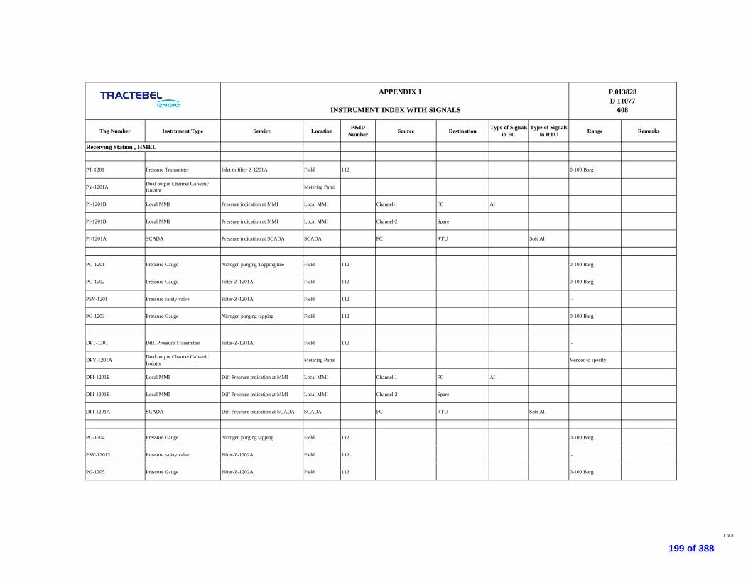
Tag Number Instrument Type Service Location P&IDNumber Source Destination Type of Signals
in FCType of Signals
in RTU Range Remarks
Receiving Station , HMEL
PT-1201 Pressure Transmitter Inlet to filter Z-1201A Field 112 0-100 Barg
PY-1201A Dual output Channel GalvanicIsolator Metering Panel
PI-1201B Local MMI Pressure indication at MMI Local MMI Channel-1 FC AI
PI-1201B Local MMI Pressure indication at MMI Local MMI Channel-2 Spare
PI-1201A SCADA Pressure indication at SCADA SCADA FC RTU Soft AI
PG-1201 Pressure Gauge Nitrogen purging Tapping line Field 112 0-100 Barg
PG-1202 Pressure Gauge Filter-Z-1201A Field 112 0-100 Barg
PSV-1201 Pressure safety valve Filter-Z-1201A Field 112 -
PG-1203 Pressure Gauge Nitrogen purging tapping Field 112 0-100 Barg
DPT-1201 Diff. Pressure Transmitter Filter-Z-1201A Field 112 -
DPY-1201A Dual output Channel GalvanicIsolator Metering Panel Vendor to specify
DPI-1201B Local MMI Diff Pressure indication at MMI Local MMI Channel-1 FC AI
DPI-1201B Local MMI Diff Pressure indication at MMI Local MMI Channel-2 Spare
DPI-1201A SCADA Diff Pressure indication at SCADA SCADA FC RTU Soft AI
PG-1204 Pressure Gauge Nitrogen purging tapping Field 112 0-100 Barg
PSV-12012 Pressure safety valve Filter-Z-1202A Field 112 -
PG-1205 Pressure Gauge Filter-Z-1202A Field 112 0-100 Barg
APPENDIX 1
INSTRUMENT INDEX WITH SIGNALS
P.013828D 11077
608
1 of 8
199 of 388
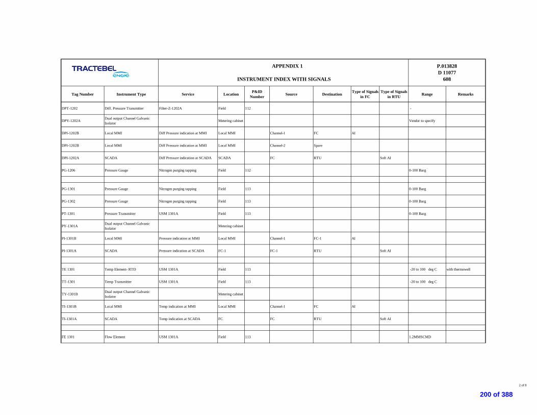
Tag Number Instrument Type Service Location P&IDNumber Source Destination Type of Signals
in FCType of Signals
in RTU Range Remarks
APPENDIX 1
INSTRUMENT INDEX WITH SIGNALS
P.013828D 11077
608
DPT-1202 Diff. Pressure Transmitter Filter-Z-1202A Field 112 -
DPY-1202A Dual output Channel GalvanicIsolator Metering cabinet Vendor to specify
DPI-1202B Local MMI Diff Pressure indication at MMI Local MMI Channel-1 FC AI
DPI-1202B Local MMI Diff Pressure indication at MMI Local MMI Channel-2 Spare
DPI-1202A SCADA Diff Pressure indication at SCADA SCADA FC RTU Soft AI
PG-1206 Pressure Gauge Nitrogen purging tapping Field 112 0-100 Barg
PG-1301 Pressure Gauge Nitrogen purging tapping Field 113 0-100 Barg
PG-1302 Pressure Gauge Nitrogen purging tapping Field 113 0-100 Barg
PT-1301 Pressure Transmitter USM 1301A Field 113 0-100 Barg
PY-1301A Dual output Channel GalvanicIsolator Metering cabinet
PI-1301B Local MMI Pressure indication at MMI Local MMI Channel-1 FC-1 AI
PI-1301A SCADA Pressure indication at SCADA FC-1 FC-1 RTU Soft AI
TE 1301 Temp Element- RTD USM 1301A Field 113 -20 to 100 deg C with thermowell
TT-1301 Temp Transmitter USM 1301A Field 113 -20 to 100 deg C
TY-1301B Dual output Channel GalvanicIsolator Metering cabinet
TI-1301B Local MMI Temp indication at MMI Local MMI Channel-1 FC AI
TI-1301A SCADA Temp indication at SCADA FC FC RTU Soft AI
FE 1301 Flow Element USM 1301A Field 113 1.2MMSCMD
2 of 8
200 of 388
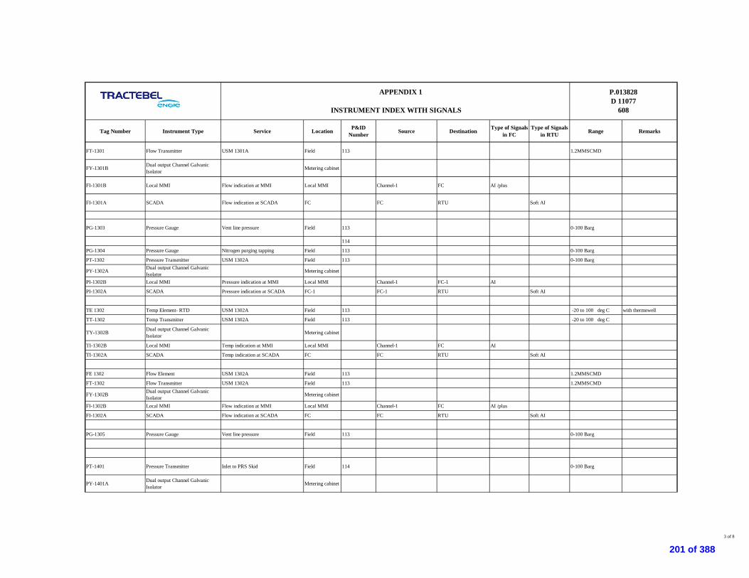
Tag Number Instrument Type Service Location P&IDNumber Source Destination Type of Signals
in FCType of Signals
in RTU Range Remarks
APPENDIX 1
INSTRUMENT INDEX WITH SIGNALS
P.013828D 11077
608
FT-1301 Flow Transmitter USM 1301A Field 113 1.2MMSCMD
FY-1301B Dual output Channel GalvanicIsolator Metering cabinet
FI-1301B Local MMI Flow indication at MMI Local MMI Channel-1 FC AI /plus
FI-1301A SCADA Flow indication at SCADA FC FC RTU Soft AI
PG-1303 Pressure Gauge Vent line pressure Field 113 0-100 Barg
114
PG-1304 Pressure Gauge Nitrogen purging tapping Field 113 0-100 Barg
PT-1302 Pressure Transmitter USM 1302A Field 113 0-100 Barg
PY-1302A Dual output Channel GalvanicIsolator Metering cabinet
PI-1302B Local MMI Pressure indication at MMI Local MMI Channel-1 FC-1 AI
PI-1302A SCADA Pressure indication at SCADA FC-1 FC-1 RTU Soft AI
TE 1302 Temp Element- RTD USM 1302A Field 113 -20 to 100 deg C with thermowell
TT-1302 Temp Transmitter USM 1302A Field 113 -20 to 100 deg C
TY-1302B Dual output Channel GalvanicIsolator Metering cabinet
TI-1302B Local MMI Temp indication at MMI Local MMI Channel-1 FC AI
TI-1302A SCADA Temp indication at SCADA FC FC RTU Soft AI
FE 1302 Flow Element USM 1302A Field 113 1.2MMSCMD
FT-1302 Flow Transmitter USM 1302A Field 113 1.2MMSCMD
FY-1302B Dual output Channel GalvanicIsolator Metering cabinet
FI-1302B Local MMI Flow indication at MMI Local MMI Channel-1 FC AI /plus
FI-1302A SCADA Flow indication at SCADA FC FC RTU Soft AI
PG-1305 Pressure Gauge Vent line pressure Field 113 0-100 Barg
PT-1401 Pressure Transmitter Inlet to PRS Skid Field 114 0-100 Barg
PY-1401A Dual output Channel GalvanicIsolator Metering cabinet
3 of 8
201 of 388

Tag Number Instrument Type Service Location P&IDNumber Source Destination Type of Signals
in FCType of Signals
in RTU Range Remarks
APPENDIX 1
INSTRUMENT INDEX WITH SIGNALS
P.013828D 11077
608
PI-1401B Local MMI Pressure indication at MMI Local MMI Channel-1 FC AI
PI-1401B Local MMI Pressure indication at MMI Local MMI Channel-2 Spare
PI-1401A SCADA Pressure indication at SCADA SCADA FC RTU Soft AI
PG-1401 Pressure Gauge Inlet to PRS Skid Field 114 0-100 Barg
PG-1412 Pressure Gauge Nitrogen Purging Field 114 0-100 Barg
TE 1401 Temp Element- RTD Inlet to PRS header Field 114 -20 to 100 deg C with thermowell
TT-1401 Temp Transmitter Inlet to PRS header Field 114 -20 to 100 deg C
TY-1401A Dual output Channel GalvanicIsolator Metering cabinet
TI-1401B Local MMI Temp indication at MMI Local MMI Channel-1 FC AI
TI-1401B Local MMI Temp indication at MMI Local MMI Channel-2 Spare AI
TI-1401A SCADA Temp indication at SCADA FC FC RTU Soft AI
PG-1407 Pressure Gauge Nitrogen Purging Field 114 0-100 Barg
SSV 1401 Slam Shut off valve ON-OFF self actuated Field 114
ZSH1401 Limit Switch (OPEN) Slam Shut off valve Field
ZYH-1401A Galvanic Isolator Metering cabinet
ZYH-1401B Relay Multiplier/Repeater Metering cabinet
ZLH-1401B Local MMI ON indication at MMI Local MMI Channel-1 FC DI
ZLH-1401B Local MMI ON indication at MMI Local MMI Channel-2 Spare
4 of 8
202 of 388

Tag Number Instrument Type Service Location P&IDNumber Source Destination Type of Signals
in FCType of Signals
in RTU Range Remarks
APPENDIX 1
INSTRUMENT INDEX WITH SIGNALS
P.013828D 11077
608
ZLH-1401A SCADA ON indication at SCADA FC FC RTU Soft DI
ZSL-1401 Limit Switch (CLOSE) Slam Shut off valve Field
ZYL-1401A Galvanic Isolator Metering cabinet
ZYL-1401B Relay Multiplier/Repeater Metering cabinet
ZLL-1401B Local MMI OFF indication at MMI Local MMI Channel-1 FC DI
ZLL-1401B Local MMI OFF indication at MMI Local MMI Channel-2 Spare
ZLL-1401A SCADA OFF indication at SCADA FC FC RTU Soft DI
PG-1413 Pressure Gauge Vent line Field 114 0-60 Barg
PG-1402 Pressure Gauge Down stream of Monitor Field 114 0-60 Barg
PG-1403 Pressure Gauge Down stream of PRS Field 114 0-60 Barg
PSV-1401 Pressure Safety Valve Down stream of PRS Field 114
PG-1414 Pressure Gauge Vent line Field 114 0-60 Barg
PG-1408 Pressure Gauge Nitrogen purging Field 114 0-60 Barg
PG-1410 Pressure Gauge Nitrogen Purging Field 114 0-100 Barg
SSV 1402 Slam Shut off valve ON-OFF self actuated Field 114
ZSH1402 Limit Switch (OPEN) Slam Shut off valve Field
ZYH-1402A Galvanic Isolator Metering cabinet
ZYH-14102 Relay Multiplier/Repeater Metering cabinet
5 of 8
203 of 388

Tag Number Instrument Type Service Location P&IDNumber Source Destination Type of Signals
in FCType of Signals
in RTU Range Remarks
APPENDIX 1
INSTRUMENT INDEX WITH SIGNALS
P.013828D 11077
608
ZLH-1402B Local MMI ON indication at MMI Local MMI Channel-1 FC DI
ZLH-1402B Local MMI ON indication at MMI Local MMI Channel-2 Spare
ZLH-1402A SCADA ON indication at SCADA FC FC RTU Soft DI
ZSL-1402 Limit Switch (CLOSE) Slam Shut off valve Field
ZYL-1402A Galvanic Isolator Metering cabinet
ZYL-1402B Relay Multiplier/Repeater Metering cabinet
ZLL-1402B Local MMI OFF indication at MMI Local MMI Channel-1 FC DI
ZLL-1402B Local MMI OFF indication at MMI Local MMI Channel-2 Spare
ZLL-1402A SCADA OFF indication at SCADA FC FC RTU Soft DI
PG-1404 Pressure Gauge Down stream of Monitor Field 114 0-60 Barg
PG-1405 Pressure Gauge Down stream of PRS Field 114 0-60 Barg
PSV-1402 Pressure Safety Valve Down stream of PRS Field 114
PG-1411 Pressure Gauge Nitrogen purging Field 114 0-60 Barg
6 of 8
204 of 388

Tag Number Instrument Type Service Location P&IDNumber Source Destination Type of Signals
in FCType of Signals
in RTU Range Remarks
APPENDIX 1
INSTRUMENT INDEX WITH SIGNALS
P.013828D 11077
608
PT-1402 Pressure Transmitter Discharge of PRS Skid Field 114 0-60 Barg
PY-1402A Dual output Channel GalvanicIsolator Metering cabinet
PI-1402B Local MMI Pressure indication at MMI Local MMI Channel-1 FC AI
PI-1402B Local MMI Pressure indication at MMI Local MMI Channel-2 Spare
PI-1402A SCADA Pressure indication at SCADA SCADA FC RTU Soft AI
PG-1406 Pressure Gauge Discharge of PRS Skid Field 114 0-60 Barg
PG-1409 Pressure Gauge Nitrogen Purging Field 114 0-60 Barg
TE 1402 Temp Element- RTD Discharge of PRS Skid Field 114 -20 to 100 deg C with thermowell
TT-1402 Temp Transmitter Discharge of PRS Skid Field 114 -20 to 100 deg C
TY-1402A Dual output Channel GalvanicIsolator Metering cabinet
TI-1402B Local MMI Temp indication at MMI Local MMI Channel-1 FC AI
TI-1402B Local MMI Temp indication at MMI Local MMI Channel-2 Spare AI
TI-1402A SCADA Temp indication at SCADA FC FC RTU Soft AI
Following are the numbers of communication ports required in Flow computer and Gas chromatograph.
Modbus serial port RS 485 shall be master and slave configruable
Communication ports details
7 of 8
205 of 388

Tag Number Instrument Type Service Location P&IDNumber Source Destination Type of Signals
in FCType of Signals
in RTU Range Remarks
APPENDIX 1
INSTRUMENT INDEX WITH SIGNALS
P.013828D 11077
608
From To Type
Flow computer RTU RS232/RS485
LocationEquipments
Modbus serial port RS 485/RS232 shall be configruable either RS 485 or RS 232
8 of 8
206 of 388

FUNCTIONCODE
REGISTERADDRESS
Flow computer for USM 1301A
1 Cumulative Uncorrected Volume Total Soft AI
2 Previous Hour Uncorrected Volume Total Soft AI
3 Current Hour Uncorrected Volume Total Soft AI
4 Previous Day uncorrected Volume Total Soft AI
5 Current Day Uncorrected Volume Total Soft AI
6 Cumulative Standard Volume Total Soft AI
7 Previous Hour Standard Volume Total Soft AI
8 Current Hour Standard Volume Total Soft AI
9 Previous Day Standard Volume Total Soft AI
10 Current Day Standard Volume Total Soft AI
11 Cumulative Mass Total Soft AI
12 Previous Hour Mass Total Soft AI
13 Current Hour Mass Total Soft AI
14 Previous Day Mass Total Soft AI
15 Current Day Mass Total Soft AI
16 Cumulative Energy Total Soft AI
17 Previous Hour energy Total Soft AI
18 Current Hour energy Total Soft AI
19 Previous Day energy Total Soft AI
20 Current Day energy Total Soft AI
21 Uncorrected volume flow rate Soft AI
22 Standard volumetric flow rate Soft AI
23 Mass flowrate Soft AI
24 Energy flowrate Soft AI
25 In Use Pressure Soft AI
26 In Use Temperature Soft AI
27 In Use Flow Soft AI
28 In use calorific value Soft AI
29 In Use Standard Density Soft AI
30 In Use Meter Density Soft AI
1 PT-1201 FC to RTU soft AI2 DPT-1201 FC to RTU soft AI3 DPT-1202 FC to RTU soft AI4 PT-1301 FC to RTU soft AI5 FT-1301 FC to RTU soft AI6 TT-1301 FC to RTU soft AI7 PT-1302 FC to RTU soft AI8 FT-1302 FC to RTU soft AI9 TT-1302 FC to RTU soft AI10 PT-1401 FC to RTU soft AI11 TT-1401 FC to RTU soft AI12 ZSL1401 FC to RTU soft AI13 ZSH1401 FC to RTU soft AI14 ZSL1402 FC to RTU soft AI15 ZSH1402 FC to RTU soft AI16 TT1402 FC to RTU soft AI17 PT1402 FC to RTU soft AI
Type of SignalMODBUS DETAILS
Remark
Soft signals from FC to RTU at Receiving Terminal at HMEL
Typical Soft signals from flow computer to RTU panel at Receiving station at HMEL
FC to RTU Panel
APPENDIX 2
INSTRUMENT IO POINT DATABASE
Tag Number Service Location
P.013828D 11077
608
Page 1 of 1
207 of 388
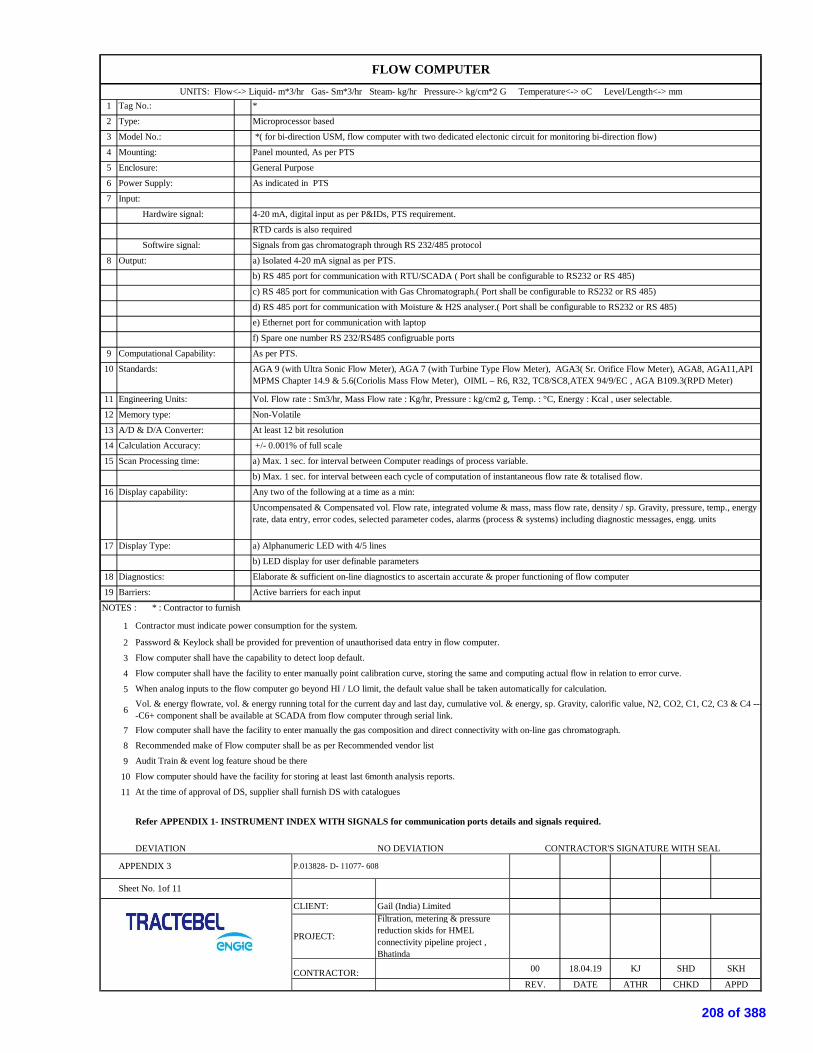
1
2
3
4
5
6
7
8
9
10
11
12
13
14
15
16
17
18
19
NOTES : * : Contractor to furnish
1
2
3
4
5
6
78
9
10
11
DEVIATION NO DEVIATION CONTRACTOR'S SIGNATURE WITH SEAL
c) RS 485 port for communication with Gas Chromatograph.( Port shall be configurable to RS232 or RS 485)
d) RS 485 port for communication with Moisture & H2S analyser.( Port shall be configurable to RS232 or RS 485)
e) Ethernet port for communication with laptop
f) Spare one number RS 232/RS485 configruable ports
Model No.: *( for bi-direction USM, flow computer with two dedicated electonic circuit for monitoring bi-direction flow)
Mounting:
Input:
FLOW COMPUTERUNITS: Flow<-> Liquid- m*3/hr Gas- Sm*3/hr Steam- kg/hr Pressure-> kg/cm*2 G Temperature<-> oC Level/Length<-> mm
Tag No.: *
Type: Microprocessor based
Refer APPENDIX 1- INSTRUMENT INDEX WITH SIGNALS for communication ports details and signals required.
Hardwire signal: 4-20 mA, digital input as per P&IDs, PTS requirement.
Panel mounted, As per PTS
Enclosure: General Purpose
Power Supply: As indicated in PTS
b) RS 485 port for communication with RTU/SCADA ( Port shall be configurable to RS232 or RS 485)
Computational Capability: As per PTS.
RTD cards is also required
Output: a) Isolated 4-20 mA signal as per PTS.
Signals from gas chromatograph through RS 232/485 protocol Softwire signal:
Engineering Units: Vol. Flow rate : Sm3/hr, Mass Flow rate : Kg/hr, Pressure : kg/cm2 g, Temp. : °C, Energy : Kcal , user selectable.
Memory type: Non-Volatile
Standards: AGA 9 (with Ultra Sonic Flow Meter), AGA 7 (with Turbine Type Flow Meter), AGA3( Sr. Orifice Flow Meter), AGA8, AGA11,APIMPMS Chapter 14.9 & 5.6(Coriolis Mass Flow Meter), OIML – R6, R32, TC8/SC8,ATEX 94/9/EC , AGA B109.3(RPD Meter)
Scan Processing time: a) Max. 1 sec. for interval between Computer readings of process variable.
b) Max. 1 sec. for interval between each cycle of computation of instantaneous flow rate & totalised flow.
A/D & D/A Converter: At least 12 bit resolution
Calculation Accuracy: +/- 0.001% of full scale
Display Type: a) Alphanumeric LED with 4/5 lines
b) LED display for user definable parameters
Display capability: Any two of the following at a time as a min:
Uncompensated & Compensated vol. Flow rate, integrated volume & mass, mass flow rate, density / sp. Gravity, pressure, temp., energyrate, data entry, error codes, selected parameter codes, alarms (process & systems) including diagnostic messages, engg. units
Barriers: Active barriers for each input
Contractor must indicate power consumption for the system.
Password & Keylock shall be provided for prevention of unauthorised data entry in flow computer.
Diagnostics: Elaborate & sufficient on-line diagnostics to ascertain accurate & proper functioning of flow computer
Flow computer shall have the capability to detect loop default.
Flow computer shall have the facility to enter manually point calibration curve, storing the same and computing actual flow in relation to error curve.
When analog inputs to the flow computer go beyond HI / LO limit, the default value shall be taken automatically for calculation.Vol. & energy flowrate, vol. & energy running total for the current day and last day, cumulative vol. & energy, sp. Gravity, calorific value, N2, CO2, C1, C2, C3 & C4 ----C6+ component shall be available at SCADA from flow computer through serial link.Flow computer shall have the facility to enter manually the gas composition and direct connectivity with on-line gas chromatograph.
APPENDIX 3 P.013828- D- 11077- 608
Recommended make of Flow computer shall be as per Recommended vendor list
Sheet No. 1of 11
CLIENT: Gail (India) Limited
ATHR
Audit Train & event log feature shoud be there
PROJECT:
Filtration, metering & pressurereduction skids for HMELconnectivity pipeline project ,Bhatinda
SKH
APPD
Flow computer should have the facility for storing at least last 6month analysis reports.
At the time of approval of DS, supplier shall furnish DS with catalogues
CONTRACTOR:REV.
00 18.04.19
CHKDDATE
KJ SHD
208 of 388

1 Transmission & Indication --
2 --
3 MFR. Std. --4 Yoke --
5 --
6 WP to IP 65 as per IEC 60529 20 Silicone Oil7 Yes 21 100% of span
8 Power Supply:- 24 V DC 22
9 Cable Entry:- 1/2" NPT(F) with aluminium plug 23 PTFE10 Accuracy:- +/- 0.075% of span (Note1) 24 *11 Rangeability:- 40:1 or better12 Transmitter Output:- 4-20 mA DC MISCELLANEOUS13 Load driving capability :- 600 ohms at 24 V DC 25 Over Range Protection:- Yes
26 Options:-14 Natural Gas a) Intrinsically safe output meter :- Yes (LED in Engg. Unit)15 Diaphragm b) Air Filter Regulator:- --16 SS316 c) Mounting accessories suitable for 2" NB pipe:- Yes17 SS316L d) 2 valve 3 way manifold:- Yes
18
Bottom 27 Model :- *19 -- 28 Quantity :- *
-- -- -- -- --
* * * * * * * * Natural Gas a,c,d
NOTES:*: Contractor to furnish
1 Accuracy includes the combined effect of repeatability, linearity,hysteresis etc and For Metering PT shall have accuracy of 0.04 % of the span2 Operating principle of transmitters shall be capacitance / piezo resistance.3 Process data shall be as per PTS-Instrumentation package unit.4 At the time of approval of DS, supplier shall furnish DS with catalogue.
DEVIATION NO DEVIATION CONTRACTOR'S SIGNATURE WITH SEAL
Armour Flexible Material:-Mounting:- Capillary length:-
Elec. Area Class:-
OPTIONSMAX.
Case:-
IEC Zone 1, Gr. IIA/IIB, Temp. class T4 Flushing/Filling Conn. with
Zero & Span adjustment:-
PRESSURE TRANSMITTER
UNITS: Flow<-> Liquid- m*3/hr Gas- Sm*3/hr Steam- kg/hr Pressure-> kg/cm*2 G Temperature<-> oC Level/Length<-> mm
Function:- Capillary Material:-
Type:- 2 Wire, Electronic smart transmitter withHART Protocol of latest version Armour Flexible:-
Continuously adjustable externally, non-interactive type
Adapter "O" Ring:-Body Rating:-
Enclosure:- Fill Fluid:-Intrinsically Safe:- Zero Suppression & Elevation:-
Element Material:-
Process Connection:- 1/2" NPT(F) thru flange adapter with plug
Measuring Unit:-Service:-Element:-Body Material:-
Process Conn.:-Size & Rating:-
Process Conn. Location:-
OP.
Facing and Finish:-
Diaphragm Seal:-Wetted Parts Material:-Other Material:-
SPANSL. NO. TAG NO.
PRESSURE TEMPERATURE RANGE
OP. MAX.
P.013828- D- 11077- 608
DES. SETSERVICE
DES.
Sheet No. 2 of 11
APPENDIX 3
CLIENT: Gail (India) Limited
CONTRACTOR: 00 18.04.19
PROJECT:
Filtration, metering & pressurereduction skids for HMELconnectivity pipeline project ,Bhatinda
KJ SHD SKH
REV. DATE ATHR CHKD APPD
209 of 388

1 Transmission & Indication --
2 --3 MFR. Std. --4 Yoke --5 IEC Zone 1, Gr. IIA/IIB, Temp. class T6 --6 WP to IP 65 as per IEC 60529 20 Silicone Oil7 Yes 21 100% of span
8 Power Supply:- 24 V DC 22
9 Cable Entry:- 1/2" NPT(F) with aluminium plug 23 PTFE10 Accuracy:- +/- 0.075% of span (Note1) 24 *11 Repeatability:- 40:1 or better12 Transmitter Output:- 4-20 mA DC MISCELLANEOUS13 Load driving capability :- 600 ohms at 24 V DC 25 Over Range Protection:- Yes
26 Options:-14 Natural Gas a) Intrinsically safe output meter :- Yes (LCD in Engg. Unit)15 Diaphragm b) Air Filter Regulator:- --16 SS316 c) Mounting accessories suitable for 2" NB pipe:- Yes17 SS316L d) 5 valve manifold:- Yes
18
Bottom 27 Model :- *19 -- 28 Quantity :- *
-- -- -- -- --
* * * Natural Gas a,c,d
NOTES:*: Contractor to furnish
1 Accuracy includes the combined effect of repeatability, linearity, hysteresis etc.2 Operating principle of transmitters shall be capacitance / piezo resistance.3 Process dada shall be as per PTS-Instrumentation package unit.4 At the time of approval of DS, supplier shall furnish DS with Catalogues
DEVIATION NO DEVIATION CONTRACTOR'S SIGNATURE WITH SEAL
As per attached P&ID
Process Conn. Location:-
Case:- Armour Flexible Material:-Mounting:- Capillary length:-Elec. Area Class:- Flushing/Filling Conn. with
Measuring Unit:-Service:-
DIFFERENTIAL PRESSURE TRANSMITTER
UNITS: Flow<-> Liquid- m*3/hr Gas- Sm*3/hr Steam- kg/hr Pressure-> kg/cm*2 G Temperature<-> oC Level/Length<-> mm
Function:- Capillary Material:-
Type:- 2 Wire, Electronic smart transmitterwith HART Protocol of latest version Armour Flexible:-
Continuously adjustable externally, non-interactive type
Adapter "O" Ring:-Body Rating:-
Enclosure:- Fill Fluid:-Intrinsically Safe:- Zero Suppression & Elevation:-
Zero & Span adjustment:-
Element:-Body Material:-
Diaphragm Seal:-Wetted Parts Material:-Other Material:-Process Conn.:-
Element Material:-
Process Connection:-
Size & Rating:-Facing and Finish:-
SL.NO. SET MAX.
ZEROSUPP. mm
H20
P.013828- D- 11077- 608
PRESSURE TEMP.
DES. MAX.TAG NO.
DIFF. RANGESERVICE OPTIONS
SPAN DES.
ZEROELEV. mm
H20
Sheet No. 3 of 11
APPENDIX 3
CLIENT: Gail (India) Limited
CONTRACTOR:
PROJECT:
Filtration, metering & pressurereduction skids for HMELconnectivity pipeline project ,Bhatinda
REV. DATE ATHR
00 18.04.19
CHKD APPD
KJ SHD SKH
210 of 388

1 TEIND-STD-G-J-4002 Note - 3 12 1/2" NPT
2 4 Wire RTD 13 Two
3 Duplex 14 WP to IP 66 as per IEC 60529 / IS 2147
4 As per DIN 43760
5 Pt100 15 SS316
6 100 Ohm 16
7 Hermatically Sealed 18 As per attached P & ID
8 19 1/2" NPT
8 mm 20 TEIND-STD-G-J-4006
SS316 21
9 SS316
10 Four Wires a) 150 mm
b) ________________
11 c) ________________
22 Quantity :- *
23 Accuracy:-
* * * a
NOTES: 1 Element length shall be suitable for thermowell.2
3 Process dada shall be as per PTS-Instrumentation package unit.4 At the time of approval of DS, supplier shall furnish DS with Catalogues and ,wake frequency calculation.5 Thermowell shall be of 900# rating
* vendor to furnish.
DEVIATION NO DEVIATION CONTRACTOR'S SIGNATURE WITH SEAL
RTD
UNITS: Flow<-> Liquid- m*3/hr Gas- Sm*3/hr Steam- kg/hr Pressure-> kg/cm*2 G Temperature<-> oC Level/Length<-> mm
Assembly as per Drawing:- Cable Entry:-
Element: No. of Entries:-
No. of Elements:- Enclosure Type:-
Calibration:-
Drilled bar stock upto immersion length 500 mm,otherwise fabricated
Leads:- Process Conn:-
Sheath: Inst. Conn.:-
Thermowell:
Element Material:- Material:-
Resistance at 0°C:- Construction:-
No. of Wires:- Extra Nipple Extens
O.D.:- Thermowell Dwg:-
Matl.:- Options:-
Nipple & Union Matl.:-
Head:-
Head Cover Type:- Screw Cap of Die Cast Aluminium with SS Chain
SL.NO. TAG NO.
TEMP. WELL DIM. FLANGE
Shall be Class A
LINE NO. / VESSEL NO./ PIPING CLASS OPTION
NOR. MAX. DES. U T MATERIAL RATING, FACING,FINISH
APPENDIX 3
As per PipingSpecification
As per PipingSpecification
Thermowell's immersion length shall be selected in such a way that tip of the thermowell shall preferably be at the centre of pipe to sense temperature properly.
PROJECT:
Filtration, metering & pressurereduction skids for HMELconnectivity pipeline project ,Bhatinda
CLIENT: Gail (India) Limited
CHKD
CONTRACTOR: 00 18.04.19 KJ SHD
APPD
SKH
P.013828- D- 11077- 608
Sheet No. 4 of 11
REV. DATE ATHR
211 of 388

1 Function of Temperature shall be Transmission & Indication.2 2 Wire, Electronic Smart with HART protocol of latest version3 MFR. Std.4 Yoke5 WP to IP 65 as per IEC 60529 / IS 21476 Elec. Area Class:- IEC Zone 1, Gr. IIA/IIB, temp. class T47 Yes8 24 V DC9 Cable Entry:- 1/2" NPT(F)
10 Accuracy:- +/- 0.20% of FSD11 Self Diagnostic Facility:- Yes12 Cold Junction compensation :- --13 Transmitter Output:- 4-20 mA DC14 Load Capability:- 600 ohms at 24V DC15 Pt100 , 4 Wire16 As per DIN 43760
17 Options:-a) Mount. Acc. For 2" pipe:- Yesb) Yes (In Engg. Unit)
18 Model :- *19 *
* Natural Gas a,b*
NOTES:* : Contractor to furnish
1 Process data shall be as per PTS-Instrumentation package unit.2 At the time of approval of DS, supplier shall furnish DS with catalogue.3 TT shall be applicable for 4 wire RTD.
DEVIATION NO DEVIATION CONTRACTOR'S SIGNATURE WITH SEAL
Enclosure:-
Intrinsically Safe:-Power Supply:-
TEMPERATURE TRANSMITTER
UNITS: Flow<-> Liquid- m*3/hr Gas- Sm*3/hr Steam- kg/hr Pressure-> kg/cm*2 G Temperature<-> oC Level/Length<-> mm
Function:-Type:-Case:-Mounting:-
SL.NO. TAG No. RANGE
Quantity :-
Intrinsically safe output meter (LED) :-
Sensor Element:-Calibration:-
P.013828- D- 11077- 608
DES.
TEMP.SERVICE OPTION
NOR. MAX.
Sheet No. 5 of 11
APPENDIX 3
CLIENT: Gail (India) Limited
CONTRACTOR:
PROJECT:
Filtration, metering & pressurereduction skids for HMELconnectivity pipeline project ,Bhatinda
REV. DATE ATHR
00 18.04.19
CHKD APPD
KJ SHD SKH
212 of 388
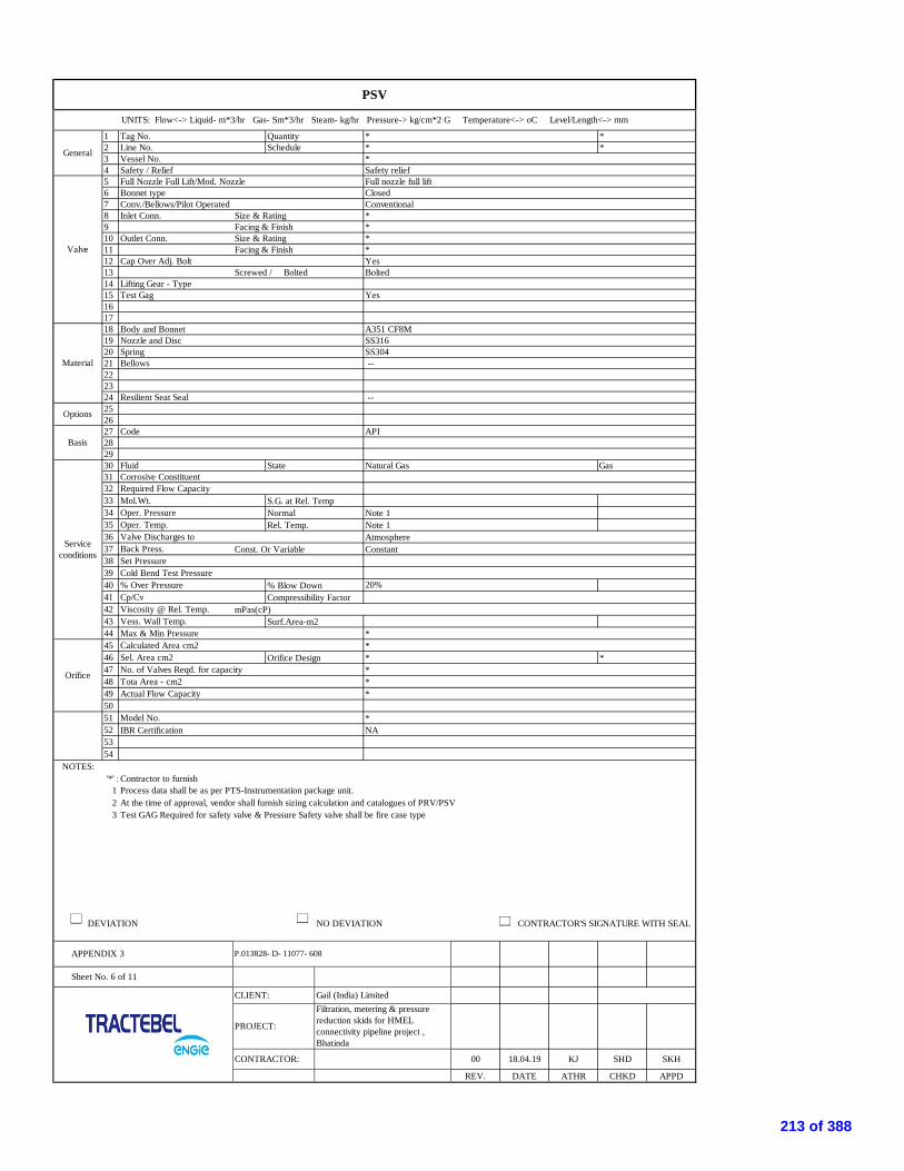
1 Tag No. Quantity * *2 Line No. Schedule * *3 Vessel No. *4 Safety / Relief Safety relief5 Full Nozzle Full Lift/Mod. Nozzle Full nozzle full lift6 Bonnet type Closed7 Conv./Bellows/Pilot Operated Conventional8 Inlet Conn. Size & Rating *9 Facing & Finish *10 Outlet Conn. Size & Rating *11 Facing & Finish *12 Cap Over Adj. Bolt Yes13 Screwed / Bolted Bolted14 Lifting Gear - Type15 Test Gag Yes161718 Body and Bonnet A351 CF8M19 Nozzle and Disc SS31620 Spring SS30421 Bellows --222324 Resilient Seat Seal --252627 Code API282930 Fluid State Natural Gas Gas31 Corrosive Constituent32 Required Flow Capacity33 Mol.Wt. S.G. at Rel. Temp34 Oper. Pressure Normal Note 135 Oper. Temp. Rel. Temp. Note 136 Valve Discharges to Atmosphere37 Back Press. Const. Or Variable Constant38 Set Pressure39 Cold Bend Test Pressure40 % Over Pressure % Blow Down41 Cp/Cv Compressibility Factor42 Viscosity @ Rel. Temp. mPas(cP)43 Vess. Wall Temp. Surf.Area-m244 Max & Min Pressure *45 Calculated Area cm2 *46 Sel. Area cm2 Orifice Design * *47 No. of Valves Reqd. for capacity *48 Tota Area - cm2 *49 Actual Flow Capacity *5051 Model No. *52 IBR Certification NA5354
NOTES: '*' : Contractor to furnish
1 Process data shall be as per PTS-Instrumentation package unit.2 At the time of approval, vendor shall furnish sizing calculation and catalogues of PRV/PSV3 Test GAG Required for safety valve & Pressure Safety valve shall be fire case type
DEVIATION NO DEVIATION CONTRACTOR'S SIGNATURE WITH SEAL
20%
Options
Basis
Serviceconditions
PSV
UNITS: Flow<-> Liquid- m*3/hr Gas- Sm*3/hr Steam- kg/hr Pressure-> kg/cm*2 G Temperature<-> oC Level/Length<-> mm
General
Valve
Material
Orifice
Sheet No. 6 of 11
APPENDIX 3 P.013828- D- 11077- 608
CLIENT: Gail (India) Limited
00 18.04.19 KJ SHD
PROJECT:
Filtration, metering & pressurereduction skids for HMELconnectivity pipeline project ,Bhatinda
SKH
REV. DATE ATHR CHKD APPD
CONTRACTOR:
213 of 388

1 Direct 15 Diaphargm Seal:- --
2 Local Type:- --
3 150 mm Wetted Parts Material:- --
White with black inscriptions Others Material:- --
4 SS316 Process Connection: Size & Rating --
5 Bayonet type SS316 Facing & Finish:- --
6 Shatterproof glass Capillary Material:- --
7 WP to IP 65 as per IEC 60529 / IS 2147 Armour - Flexible Material:- --
8 Bourdon Capillary Length:- --
9 SS316 Flushing/Filling connection with:- --
10 SS316 16 Over Range Protection:- 130% of FSD
11 +/-1% of FSD 17 Blow Out Protection:- Yes
12 Micropointer 18 Options :- a) Snubber
13 1/2" NPT(M) b) Syphon c) Gauge Saver
Connection Location:- Bottom d) Liquid Filled casing e) Vaccum Protection
14 SS316 f) Solid front g) Two valve manifold
19 Quantity :- *
* Natural Gas e,f,g
NOTES: '*' : Contractor to furnish
1 Process data shall be as per PTS-Instrumentation package unit.2 At the time of approval of DS, supplier shall furnish DS with Catalogues.
DEVIATION NO DEVIATION CONTRACTOR'S SIGNATURE WITH SEAL
Accuracy:-
Element Material:-
Socket Material
Zero adjustment:-
Colour:-
Case Material:-
Bezel Ring:-
Window Material:-
Enclosure:-
Pressure Element:-
MAX.
PRESSURE GAUGE
UNITS: Flow<-> Liquid- m*3/hr Gas- Sm*3/hr Steam- kg/hr Pressure-> kg/cm*2 G Temperature<-> oC Level/Length<-> mm
Type:-
Mounting:-
Dial Size:-
SL. NO. TAG NO. RANGEPRESSURE
DES.
Connection:-
Movement:-
TEMPERATURESERVICE OPTIONS
OP. MAX. DES. OP.
P.013828- D- 11077- 608
Note 1 Note 1
Sheet No. 7 of 11
APPENDIX 3
CLIENT: Gail (India) Limited
CONTRACTOR: 00 18.04.19
PROJECT:
Filtration, metering & pressurereduction skids for HMELconnectivity pipeline project ,Bhatinda
KJ SHD SKH
REV. DATE ATHR CHKD APPD
214 of 388

1 Tag No. Quantity * *2 Inlet Line No. *3 Outlet Line No. *4 Service Natural Gas5 Line Size *6 Inlet Line I.D. Outlet Line I.D. As per ANSI B 36.10 As per ANSI B 36.107 Type of Body Slam Shut8 Body Size Port Size * *9 Guiding No. of Ports * *10 End Conn:Flgd.Size, Rating & Material *11 Facing & Finish *12 Body Material ASTM A 350 LF213 Bonnet Type Plain14 Packing Material PTFE15 Lubricator Isol. Valve *16 Type of Regulator *17 Trim Mat.Plug/Disc./Ball & Seat SS31618 Other Wetted Parts SS31619 Soft Seating Material * *20 ANSI Leakage Class VI21 Type Pneumatic22 Close At Open At * Manual Reset only23 Failure Position FC24 Handwheel Yes25 Pneumatic Supply Pressure Natural gas shall be used as supply26 Input Output * *27 Bypass Gauges * *28 Solenoid Valve *29 I/P Converter *30 Filter With Gauge *31 Limit Switch Yes32 Fluid State Natural Gas Gas33 Flow Liquid-Min / Normal / Max. NA34 Flow Gas-Min / Normal / Max. * Note 135 Flow Water-Min / Normal / Max. NA36 Inlet Pressure *37 Set Pressure *38 D.P. Shut Off *39 Temperature - Oper. Max. * Note 1 *40 Oper. S.G. Mol. Wt. *41 Cp/Cv Compress.Factor *42 Flash% Visc.mPas (oper) *43 Deg. of Superheat % Solids *44 Vapour Pr. Critical Pr. *45 Cv Min. Cv Max. * *46 Cv Nor. Selected Cv * *47 Predicted Sound Level dBA <85dBA48 Inlet Velocity m/s *49 Valve Actuator * *50 Positioner Solenoid Valve * *51 Limit Switches *52 IBR Certification -53 Stroke Time of SSV shall be less than 1 Sec54 Accuracy of SSV shall be equal or better than 1%
NOTES: '*' : Contractor to furnish
1 Process data shall be as per PTS-Instrumentation package unit.2 Contractor must furnish sizing calculation along with the offer.3 Two nos. (one for open and one for close) Snap acting micro switch (SPDT) shall be provided for each slam shut valve.4 Limit switch enclosure shall be WP to IP 65 & EExd IIA / IIB T4 as per IEC 60079 / IS 21485 At the time of approval of DS, vendor shall furnish DS with catalogues and sizing calculation of SSV6 Maximum permitted seat velocity shall be 40 m/s.7 Local Valve position indication shall be provided.
DEVIATION NO DEVIATION CONTRACTOR'S SIGNATURES WITH SEAL
SLAM SHUT VALVE
UNITS: Flow<-> Liquid- m*3/hr Gas- Sm*3/hr Steam- kg/hr Pressure->kg/cm2 g Temperature<-> °C Level/Length<-> mm
General
Body
Actuator
Positioner
Options
Serviceconditions
Valve Data
Make
Model no.
APPENDIX 3
Sheet No. 8 of 11
P.013828- D- 11077- 608
CLIENT: Gail (India) Limited
00 18.04.19 KJ SHD
PROJECT:
Filtration, metering & pressurereduction skids for HMELconnectivity pipeline project ,Bhatinda
SKH
REV. DATE ATHR CHKD APPD
CONTRACTOR:
215 of 388

1 Tag No. Quantity * *2 Inlet Line No. * As per P&ID3 Outlet Line No. * As per P&ID4 Service Natural Gas5 Line Size *6 Inlet Line I.D. Outlet Line I.D. As per ANSI B 36.10 As per ANSI B 36.107 Type of Body *8 Body Size Port Size * *9 Guiding No. of Ports * *10 End Conn:Flgd.Size, Rating & Material *11 Facing & Finish *12 Body Material ASTM A 350 LF213 Bonnet Type *14 Packing Material PTFE15 Lubricator Isol. Valve * *16 Type of Regulator As per Letdown skid P&ID and PTS17 Trim Mat.Plug/Disc./Ball & Seat SS31618 Other Wetted Parts SS31619 Soft Seating Material - -20 ANSI Leakage Class VI21 Type Self actuated Pilot Operated22 Close At Open At * *23 Failure Position As per P&ID24 Handwheel -25 Air Supply Pressure -26 Input Output - -27 Bypass Gauges - -28 Solenoid Valve -29 I/P Converter -30 Filter With Gauge -31 Limit Switch -32 Fluid State Natural Gas Gas33 Flow Liquid-Min / Normal / Max. *34 Flow Gas-Min / Normal / Max. *35 Flow Water-Min / Normal / Max. *36 Inlet Pressure *37 Set Pressure *38 D.P. Shut Off *39 Shut off class *40 IGETD Class shall be 13 *41 Type Of PRS either working monitor or wide open *42 Temperature - Oper. Max. * *43 Oper. S.G. Mol. Wt. *44 Cp/Cv Compress.Factor *45 Flash% Visc.mPas (oper) *46 Deg. of Superheat % Solids *47 Vapour Pr. Critical Pr. *48 Cv Min. Cv Max. * *49 Cv Nor. Selected Cv * *50 Predicted Sound Level dBA < 85dBA51 Inlet Velocity m/s Shall be less than 20 m/s52 Valve Actuator * *53 Positioner Solenoid Valve * *5455 IBR Certification -56 Radiography Required
NOTES: '*' : Contractor to furnish
1 Accuracy of the regulator shall be better than 1% of set pressure.2 Contractor must furnish sizing calculation along with the offer.3 Process data shall be as per PTS-Instrumentation package unit.4 At the time of approval of DS, supplier shall furnish DS with catalogues5 Function and sizing calculation for the outlet pressure to be furnished by the supplier6 Lock up Zone of regulatot shall be maximum 5 %7 Impulse connection shall be external and Tubing connection shall be 1/2'' NPT8 Set points of the regulators shall be adjustable.9 Axial type regulators shall be preferred.
DEVIATION NO DEVIATION CONTRACTOR'S SIGNATURES WITH SEAL
Options
Serviceconditions
PRESSURE REGULATED VALVE
UNITS: Flow<-> Liquid- m*3/hr Gas- Sm*3/hr Steam- kg/hr Pressure->kg/cm2 g Temperature<-> °C Level/Length<-> mm
General
Body
Actuator
Positioner
Valve Data
Make
Model no.
APPENDIX 3 P.013828- D- 11077- 608
PROJECT:
Sheet No. 9 of 11
CLIENT: Gail (India) Limited
00 18.04.19 KJ SHD
Filtration, metering & pressurereduction skids for HMELconnectivity pipeline project ,Bhatinda
SKH
REV. DATE ATHR CHKD APPD
CONTRACTOR:
216 of 388
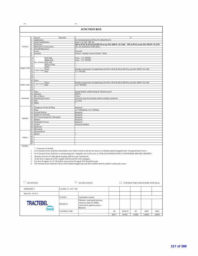
1 Tag No. Quantity * *2 Application For Instrumentation IS/Non-IS cables(Note-5)3 Area Classification Zone 1, Gr. IIA / IIB, T44 Enclosure WP to IP 65 & EExd IIA/IIB T6 as per IEC 60079 / IS 2148/ WP to IP 65 as per IEC 60529 / IS 21475 Material of Construction Die cast aluminium (LM6 alloy)6 Overall Dimension *7 Cover Screwed8 Painting Surface : Opaline Green & Inside : White910 Left Side 6 nos. - 1/2" NPT(F)11 Right Side 6 nos. - 1/2" NPT(F)12 Top Side -13 Bottom Side -14 Other -15 Type Double compression, Ni plated brass & WP to IP 65 & EExd IIB T6 as per IEC 60079 / IS 214816 Size 1/2" NPT(M)17181920 Entry21 Type Double compression, Ni plated brass & WP to IP 65 & EExd IIB T6 as per IEC 60079 / IS 214822 Size 11/2" NPT(M)232425 Type Spring loaded, antiloosening & vibration-proof26 Quantity 48 Nos.27 No. of Rows 2 Nos.28 Numbering System Terminal strips & terminals shall be suitably numbered29 Size 2.5 mm230 Make *3132 Telephone Socket & Plugs Required33 Plug 1/2" NPT(M) & 11/2" NPT(M)34 Ground Busbar Required35 Rail(s) for terminals Required36 PVC hood alongwith Cable gland Required37 Hinges Required38 Nameplate Fixture Required39 Gasket Neoprene Rubber40 Hardware41 Mounting42 Manufacturer43 Model *44454647
NOTES:* : Contractor to furnish
1 Ex d Junction boxes shall have detachable cover which is fixed to the box by means of cadmium plated triangular head / hexagonal head screws.23 Quantity and size of Cable glands & plugs shall be as per requirement.4 At the time of approval of DS, supplier shall furnish DS with catalogues5 For Non IS signals, Ex"d" JB shall be used and for IS signals WP JB shall be used6 WP Junction boxes shall have doors which shall be hinged type and these shall be fixed by plated countersunk screws.
DEVIATION NO DEVIATION CONTRACTOR'S SIGNATURE WITH SEAL
Multi Cable Cable Gland
Terminals
Options
Others
Ex d Junction boxes shall have a warning engraved / integrally cast on the cover as "ISOLATE POWER SUPPLY ELSEWHERE BEFORE OPENING".
JUNCTION BOX
General
Single Cable
No. of Entry
Cable Gland
P.013828- D- 11077- 608
Sheet No. 10 of 11
APPENDIX 3
CLIENT: Gail (India) Limited
CONTRACTOR: 00 18.04.19
PROJECT:
Filtration, metering & pressurereduction skids for HMELconnectivity pipeline project ,Bhatinda
KJ SHD SKH
REV. DATE ATHR CHKD APPD
217 of 388

1 Tag No. *2 Quantity *3 Line No./Size/Schedule *4 Application Custody transfer5 Type MULTIPATH (Minimum 4 path), transit time6 End Conn.:-Size / Rating / Schedule */ #600 / *7 -Facing & Finish Flanged/RF 125-250 AARH8 Pulses / m3 *9 Flow Range As per pipe specs10 Enclosure Weather Proof to IP6611 Cable Entry *12 Material - Body As per pipe specs *13 Material - End Connection Flanged, As per Pipe Spec *14 Bi-directional /Unidirectional Bi-Direction and unidirectional-refer P&ID15 Radiography/Charpy test REQUIRED16 ±0.2% or better17 Repeatability ±0.1% for Qt<Q<Qmax & ±0.2% for Qmin<Q<Qt18 Accuracy class Class 0.5 as per OIML R 13719 Resolution 0.001 m/s.20 Type – 2 wire / 3 wire *21 Pre - amplifier location METER MOUNTED22 Power Supply ¦ Cable Entry FROM TRANSMITTER | *23 Enclosure WP TO IP65/NEMA-424 Intrinsically Safe| Ex-proof FLAME PROOF25 Mounting Integral with USM Required26 Power Supply ¦ Cable Entry * | * *27 Output FREQUENCY & RS48528 Enclosure WP TO IP66/NEMA-429 Intrinsically Safe| Ex-proof FLAME PROOF30 Mounting METER MOUNTED
31 Meter runs (Up & Down stream)
32 Flow Conditioner/ Profiler REQUIRED33 Retractable probes REQUIRED34 Press. Tap on Meter Body REQUIRED-1/2" NPT35 Cold insulation Required36 a) On Meter (Jacket type) REQUIRED37 b) On Meter tube (Up & down stream) REQUIRED38 b) Thermowell & Inpulse tubing REQUIRED39 Fluid and State Natural gas40 Flow Min. Normal Max. Design Note - 441 Temp. Min. Normal Max. Design Note - 442 Pressure Min. Normal Max. Design Note - 443 Molecular Wt. Specifical Garvity 0.644 Viscosity (cP)45 Cp/ Cv ratio46 Max. allowable pressure drop 0.547 Compressibility Factor48 Area Classification Hazardous Zone 1 Group IIA /IIB, T4 as per IEC49 Model No. Meter Note 150 Pulser Note 1
Notes '*' : 1. Contractor to specify.
2. As per piping specification.3. As per attached P&IDs.4. Process Data shall be as per PTS-Instrumentation package unit5. The design of Ultrasonic meterhall be as per AGA 96. At the time of approval of DS, supplier shall furnish DS with catalogues and sizing calculation of turbine flow meter
DEVIATION NO DEVIATION CONTRACTOR'S SIGNATURES WITH SEAL
unidirectional-10D/As per OEM-Profiler-10D-USM-5D and bidirection 10D/As per OEM-Profiler-10D-USM-10D-Profiler-10D/As per OEM
Overall Accuracy
APPENDIX 3
ULTRASONIC FLOWMETERUNITS: Flow<-> Liquid- m*3/hr Gas- Sm*3/hr Steam- kg/hr Pressure-> barg Temperature<-> oC Level/Length<-> mm
Gen
eral
Flow
Met
erSe
rvic
eC
ondi
tions
Pre-
ampl
ifier
Puls
erO
ptio
ns
P.013828- D- 11077- 608
Sheet No. 11 of 11
18.04.19
CLIENT: Gail (India) Limited
00 KJ SHD SKH
PROJECT:
Filtration, metering & pressurereduction skids for HMELconnectivity pipeline project ,Bhatinda
CONTRACTOR:
APPDREV. DATE ATHR CHKD
218 of 388

APPENDIX-4P.013828D 11077
608
Page 1 of 1
SPARE CAPACITY
Spare capacity is depending on the type of equipment and is defined in the following table. Vendor shall consider thespares while designing the system.
ITEM DESCRIPTION SPARE QUANTITY
1 Multipair cables
Spare pairs (all pairs have to be connected to theterminals of junction boxes, marshalling racks orany other terminal strip)
20 %
2 Cable ladders and trays
Spare room for additional cables
30 %
Spare opening for cable entry in JB and meteringsystem panel with blind caps.
20%
Spare cable gland for JB and metering systempanel
20 %
3 Panel equipment: (For Metering system gaschromatograph)
Spare Relays, Indicators, Galvanic Isolators,Barriers, repeaters, signal multipliers, MCB, Pushbuttons, terminals, etc of each type mounted in themetering system panel with wiring up to terminalsfor future provision.
20% or minimum one, whicheverhigher
219 of 388
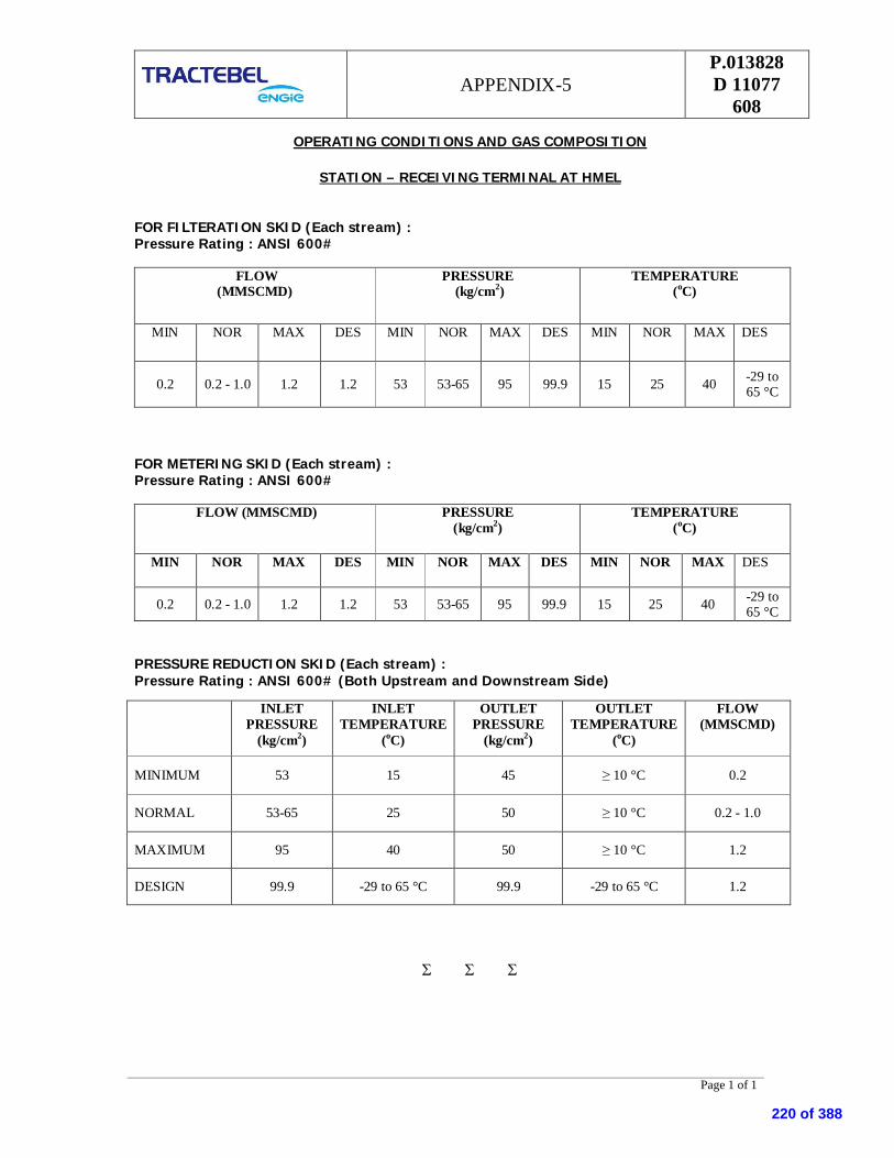
APPENDIX-5P.013828D 11077
608
Page 1 of 1
OPERATING CONDITIONS AND GAS COMPOSITION
STATION – RECEIVING TERMINAL AT HMEL
FOR FILTERATION SKID (Each stream) :Pressure Rating : ANSI 600#
FLOW(MMSCMD)
PRESSURE (kg/cm2)
TEMPERATURE(oC)
MIN NOR MAX DES MIN NOR MAX DES MIN NOR MAX DES
0.2 0.2 - 1.0 1.2 1.2 53 53-65 95 99.9 15 25 40 -29 to65 °C
FOR METERING SKID (Each stream) :Pressure Rating : ANSI 600#
FLOW (MMSCMD) PRESSURE(kg/cm2)
TEMPERATURE(oC)
MIN NOR MAX DES MIN NOR MAX DES MIN NOR MAX DES
0.2 0.2 - 1.0 1.2 1.2 53 53-65 95 99.9 15 25 40 -29 to65 °C
PRESSURE REDUCTION SKID (Each stream) :Pressure Rating : ANSI 600# (Both Upstream and Downstream Side)
INLETPRESSURE
(kg/cm2)
INLETTEMPERATURE
(oC)
OUTLETPRESSURE
(kg/cm2)
OUTLETTEMPERATURE
(oC)
FLOW(MMSCMD)
MINIMUM 53 15 45 10 °C 0.2
NORMAL 53-65 25 50 10 °C 0.2 - 1.0
MAXIMUM 95 40 50 10 °C 1.2
DESIGN 99.9 -29 to 65 °C 99.9 -29 to 65 °C 1.2
220 of 388

QAP NoRev.Prepared by KJ Checked By: SHDApproved by
M VENDOR TPIConsultant /
Owner
General Finish Job Card
Verification of
- Modal No.- Serial No.- Calibration Range- Material of construction- Customer Tag P R W W/R- Certification Lable- Process connection- Asscessories- Calibration Critical Electrical Calibration Procedure
& Job Card
CalibrationProcedure & Job
Card- Calibration / Accuracy / Range
- Load Variation Test
- Power Supply Variation Test
- Reverse Plo……….. Test
- Accessories Major Visual As per Model As per Model - Communication with H…….Communicator- Verfication of Model & Tag No.- Ov……………..Pressure Test Critical Visual
100% Product Data Sheet Product DataSheet
M P PerformC R Review
TPI W WitnessA W/R Witness of Test / Review of Certificates & Documents as per QAP
INTERNAL TEST / INSPECTION1 Job Card & ProductData Sheet
QUALITY ASSURANCE PLANPRESSURE, LEVEL, TEMPERATURE, DIFF. PRESSURE TRANSMITTER
Sr.No. Description Characteristic Class
Major
: P.013828 D 11013 61100
SKH
W/R
Reference Document RemarksDoc. / Quality
Assurance Planfor Level Guage
Inspection By
Format Of Records
100%Visual
Type of Check
W/R
Third Party Inspection AgencyFor Approval
W
R W
Quantam ofCheck
ManufacturerClient
Legend
P R
2
Critical Electrical100%
Critical Electrical 100%Witness Test / Inspection
Procedure & Job Card Procedure & JobCard
Comliance Report
Calibration Procedure& Job Card
CalibrationProcedure & Job
Card
Test & CalibrationReport
P
Page 1 of 1
221 of 388

QAP NoRev.Prepared by : KJ Checked By: SHDApproved by
M VENDOR TPI Consultant /Owner1 Bought Out Components Test Certificate Major Review 100%
Visual Major Visual 100%
Dimensional Major Dimensional 100%
2 Inprocess Inspection Dimensional Major Dimensional 100%
Functional Major Accuracy 100%
Hydro Test Major Strength100%
3 Final Inspection Dimensional Major Dimensional 100%Functional a) Pneumatic Test Major Leakage 100%
b) Set Point Test Major Accuracy100%
1) Pneumatic Test of Body & Other Parts assembly shall be Carried out at 1.5 times max.operating pressure.2) Set Point Test shall be carried out at specified pressure.
M P PerformC R Review
TPI W WitnessA W/R Witness of Test / Review of Certificates & Documents as per QAP
NOTE1) Integration & Hookup SS Tubing2)3)
Remarks
Applicable Standard /Product Datasheet
3) Seat tightness test for PCVs, Slam shut valves (shall be conducted at manufacturer’s shop and certificates shall be submitted)
P
ApplicableStandard /
ProductDatasheet
Job Card P R
W/RCustomer Data
Product Data Sheet& Job Card
Customer DataProduct DataSheet & Job
Card
Job Card W/RW
W/R
ManufacturerClient
Legend
Type ofCheck
Quantam ofCheck
Sr.No.
DescriptionAcceptance
Norms
Applicable Standard /Product Datasheet
ApplicableStandard /
ProductDatasheet
Job Card RP
Inspection ByClass
Third Party Inspection AgencyFor Approval
W/R
Characteristic
Sr. No.3 Final Inspection shall be done at Manufacturer's works.
Format OfRecords
R
Testing with N2 shall be done to Check proper tubing arrangement.
W
QUALITY ASSURANCE PLANSLAM SHUT VALVES & REGULATORS
: P.013828 D 11013 61200
SKH
ReferenceDocument
Page 1 of 1
222 of 388

QAP NoRev.Prepared by : KJApproved by
Sr.No. Component Operation Charactristics Checked Category Type/Method of
Check Referrence Document Acceptance Norm Format of Plan Remarks
P W M TPIA CRaw Material a) Dimensions MA Mechanical 100% 100% PO approved PO approved TC P R W/R
b) Chemical Analysis MA Chemical Sample _ Spec/Drg. Spec/Drg. TC P R W/R
c) Marking, Tagging MA Visual 100% 100% Approved Spec/PO Approved Spec/PO TC P W W/R
2 Routine test Accuracy HystresisRepeatability
CR Measurement 5Points
100% 100% EN 837-1 EN 837-1 Calibration Report P W W/R
Over range protection CR Visual 100% 100% EN 837-1 EN 837-1 Test Report P W W/RAccessories (If applicable) 1) Chemical Analysis MA Chemical Sample TCGuage Saver in SS 316 2) Dimensions MA Measurement 100% 100% Work Certificate
3) Leak Tightness CR Hydrotest 100% 100% Test Certificate
3 IRN P R
Note: 1) Material and Type shall be as per tender specification / datasheet.
Category: CR - Characteristics affecting safety of equipment and personnelMA - Characteristics affecting safety of PerformanceMT - Charactristics affecting safety of Appearance
M-ManufacturerTPIA-Third Party Inspection AgencyC-Client/ Counsaltanr
P-Perform
W-Witness
R-Review
Extent of Check Agency
QUALITY ASSURANCE PLANFOR PRESSURE GAUGE Checked by :
: P.013828 D 11013 61300
SHDSKH
Approved/POspecs/Datasheet/Drawing
Approved/POspecs/Datasheet/Drawing
1
W W/RP
Page 1 of 1
223 of 388

QAP NoRev.Prepared by : MAApproved by
Sr. No. ComponentOperation Characteristics Checked Category Type/ Method of check Reference document Acceptance norm Format of plan Remarks
Vendor TPIA/C M TPIA C
a) Accuracy Test MA Testing 100% 10% IEC751/DIN43760 IEC751/DIN43760 LOGBOOK/Computerized
P W W/R
b) IR at AMB & at 500VDC * * 100% 10% STD TO STD LOGBOOK/Computerized
P R W/R
c) Hot IR at 320 Deg c & 500VDC
* * 100% _ STD TO STD LOGBOOK/Computerized
P R W/R
d) N2 Test * * 100% 10% STD TO STD LOGBOOK/Computerized
P R W/R
e) Response Time test * * 10% 10% STD TO STD Test Reports P R W/Rf) Dimensions/Connection * Measurement 100% 100% Applicable Specification/
Drawing to Applicable
Specification/DrawingsDesign P R W/R
g)Weather proofness test MA/CR Testing Sample of design IP 65 IS 13947 IP 65 IS 13947 Testing certificates P R W/RThermowell
1 Raw materials ofthermowell
Chemical Composition MA analysis _ _Applicable Specification To applicable
specifications
Test Reports P R W/R
a) dimension MA measuring 100% 10% Applicable Specification to ApplicableSpecification/Drawings Log book test report P W W/R
b) hydro test MA testing 100% 10% Applicable Specification No leakage Log book test report P W W/Rc) bore concentricity test MA/CR go- no gauge 100% _ Applicable Specification/
Drawingwithin 10% of walll
thickness Log book P W W/Rd)visual MA/MT observation 100% _ Co. Std. To Co. Std. Log Book P W W/Re)workmanship/finish MA/MT observation 100% _ Co. Std. To Co. Std. Log Book P W W/Rf) Spec/ tagging MA visual 100% _ Applicable Specification/
Drawing to Applicable
Specification/DrawingsLog book P W W/R
g) threading MA thread gauge 100% _ STD TO STD Log book P W W/Rh) surface finish MT visual 100% _ STD TO STD Log book P W W/R
3 IRN P R
Note:1) Material and Type shall be as per tender specification / datasheet.Note:M-Manufacturer P-PerformTPIA-Third Party Inspection Agency R-ReviewC-Client/ Counsaltanr W-Witness
Extent of check Agency
RTD Assemblies
The resultslogged in the
log bookwould be
issued in theform of test
certificates asper DIN
2 thermowell
No leakage at40 kg/cm2
1 RTD assemblies
QUALITY ASSURANCE PLANFOR RTD AND THERMOWELL Checked by :
: P.013313 D 11013 61400
SHDAR
Page 1 of 1
224 of 388

225 of 388

226 of 388

227 of 388

228 of 388

229 of 388

230 of 388
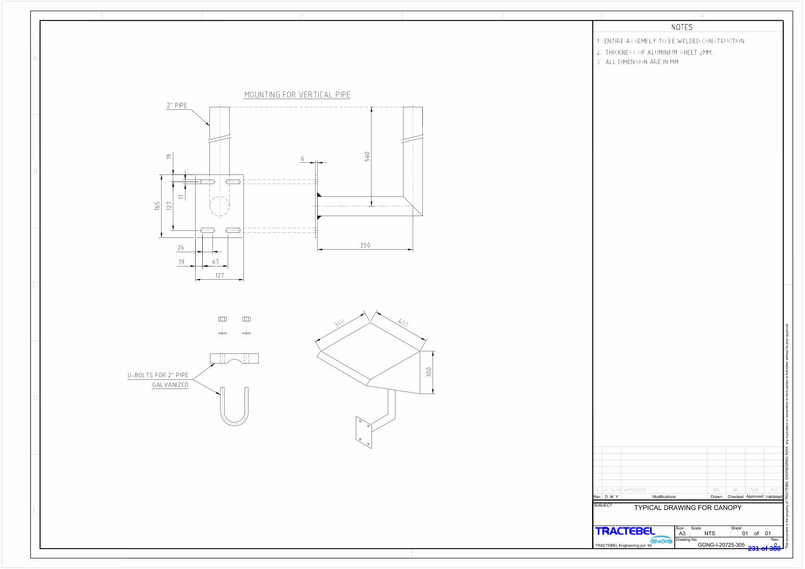
231 of 388

Project No. Discipline Code System Code Serial No.
Rev.SheetSize Scale
TRACTEBEL Engineering pvt. ltd.
SUBJECT
PROJECT
CUSTOMER
This docum
ent is the property of T
RA
CT
EB
EL E
NG
IN
EE
RIN
G IN
DIA
, any duplication or transm
ition to third parties is forbidden w
ithout its prior approval.
GAIL (India) LIMITED
GAIL
HMEL CONNECTIVITY PIPELINE PROJECT
BHATINDA
LIST OF SYMBOLS
A2 NTS 1 of 2
0
P.013828 D 21095 100
Rev. D M Y Modifications Drawn Checked Approved Validated
0 12-04-2019 ISSUED FOR APPROVAL. JV CP MS SKH
232 of 388
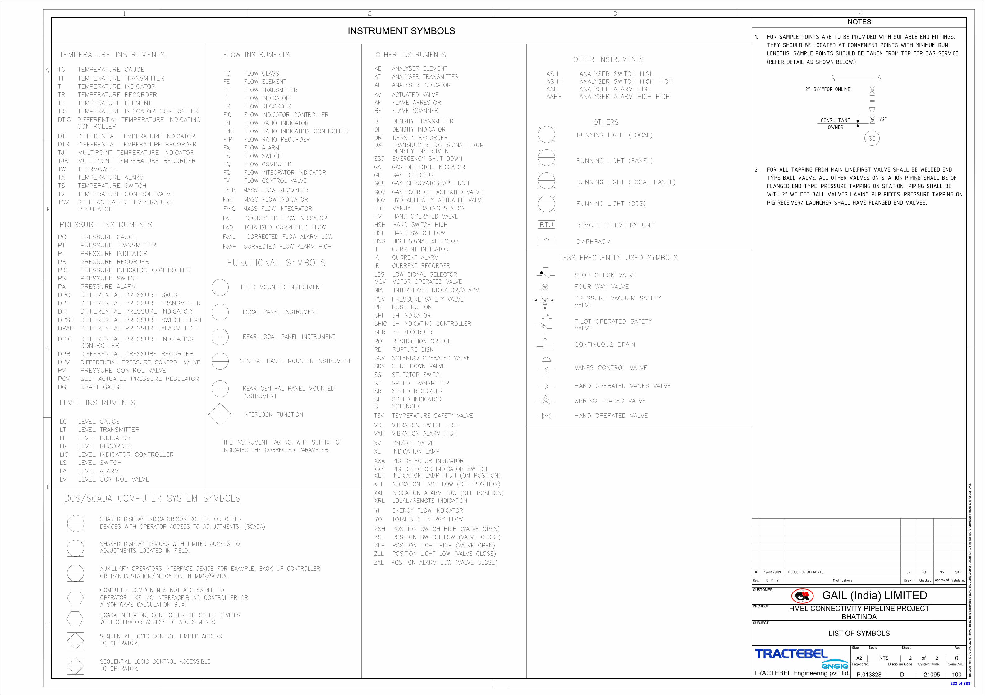
INSTRUMENT SYMBOLS
2" (3/4"FOR ONLINE)
1/2"CONSULTANTOWNER
1. FOR SAMPLE POINTS ARE TO BE PROVIDED WITH SUITABLE END FITTINGS.THEY SHOULD BE LOCATED AT CONVENIENT POINTS WITH MINIMUM RUNLENGTHS. SAMPLE POINTS SHOULD BE TAKEN FROM TOP FOR GAS SERVICE.(REFER DETAIL AS SHOWN BELOW.)
2. FOR ALL TAPPING FROM MAIN LINE,FIRST VALVE SHALL BE WELDED ENDTYPE BALL VALVE. ALL OTHER VALVES ON STATION PIPING SHALL BE OFFLANGED END TYPE. PRESSURE TAPPING ON STATION PIPING SHALL BEWITH 2" WELDED BALL VALVES HAVING PUP PIECES. PRESSURE TAPPING ONPIG RECEIVER/ LAUNCHER SHALL HAVE FLANGED END VALVES.
NOTES
Project No. Discipline Code System Code Serial No.
Rev.SheetSize Scale
TRACTEBEL Engineering pvt. ltd.
SUBJECT
PROJECT
CUSTOMER
This docum
ent is the property of T
RA
CT
EB
EL E
NG
IN
EE
RIN
G IN
DIA
, any duplication or transm
ition to third parties is forbidden w
ithout its prior approval.
GAIL (India) LIMITED
GAIL
HMEL CONNECTIVITY PIPELINE PROJECT
BHATINDA
LIST OF SYMBOLS
A2 NTS 2 of 2
0
P.013828 D 21095 100
Rev. D M Y Modifications Drawn Checked Approved Validated
0 12-04-2019 ISSUED FOR APPROVAL. JV CP MS SKH
233 of 388

NOTES
Project No. Discipline Code System Code Serial No.
Rev.SheetSize Scale
SUBJECT
PROJECT
CUSTOMER
This docum
ent is the property of T
RA
CT
EB
EL E
NG
IN
EE
RIN
G IN
DIA
, any duplication or transm
ition to third parties is forbidden w
ithout its prior approval.
GAIL (India) LIMITED
HMEL CONNECTIVITY
PIPELINE PROJECT, BHATINDA
PIPING & INSTRUMENTATION DIAGRAM
FILTERATION SKID AT HMEL (RECEIVING STATION)
A2 NTS 1 of 1
A
P.013828 D 21097 401
Rev. D M Y Modifications Drawn Checked
Approved
Validated
LEGEND
DESIGN
FLOW : 1.2 MMSCMD
PRESSURE : 98 barg
TEMP. : -20°C TO 65°C
12" x 600#
NOTE-6
NOTE-7
234 of 388

235 of 388
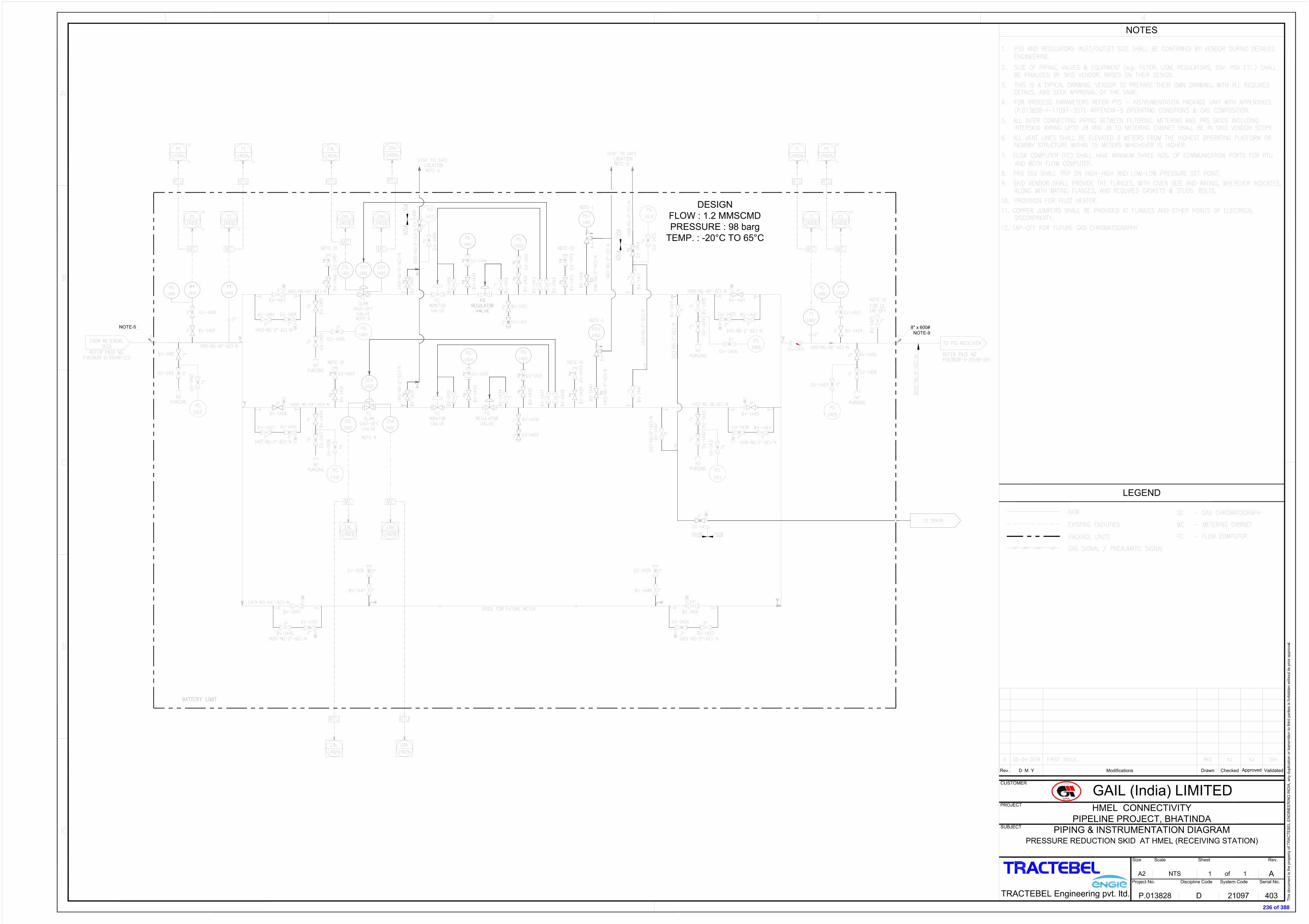
236 of 388

237 of 388

238 of 388

239 of 388

240 of 388

241 of 388
GENERAL TECHNICAL
SPECIFICATION
70000 740
GTS/402
PIPELINE VALVES
7 14/09/09 Logo Changed AA PK NC
6 22/09/08 Logo Changed AA PK NC
5 27/01/04 Updated + Logo Changed MRY MRT DKB
4 30/10/02 Updated MRY LEP LEP
3 01/07/02 Updated MRY LEP LEP
2 07/11/01 Updated AES LEP LEP
1 22/06/00 First issue AES LEP LEP
Rev. Date Subject of revision Author Checked Approved
242 of 388
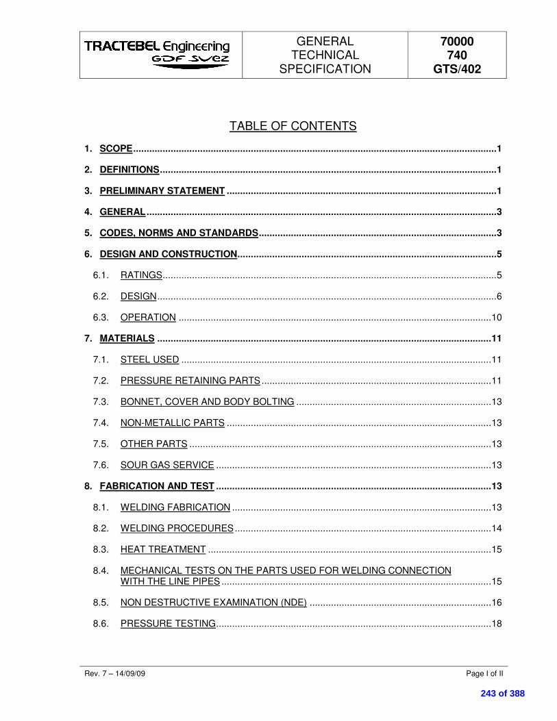
GENERAL TECHNICAL
SPECIFICATION
70000 740
GTS/402
Rev. 7 – 14/09/09 Page I of II
TABLE OF CONTENTS
1. SCOPE ........................................................................................................................................ 1
2. DEFINITIONS .............................................................................................................................. 1
3. PRELIMINARY STATEMENT ..................................................................................................... 1
4. GENERAL ................................................................................................................................... 3
5. CODES, NORMS AND STANDARDS ......................................................................................... 3
6. DESIGN AND CONSTRUCTION ................................................................................................. 5
6.1. RATINGS ............................................................................................................................. 5
6.2. DESIGN ............................................................................................................................... 6
6.3. OPERATION ..................................................................................................................... 10
7. MATERIALS ............................................................................................................................. 11
7.1. STEEL USED .................................................................................................................... 11
7.2. PRESSURE RETAINING PARTS ...................................................................................... 11
7.3. BONNET, COVER AND BODY BOLTING ......................................................................... 13
7.4. NON-METALLIC PARTS ................................................................................................... 13
7.5. OTHER PARTS ................................................................................................................. 13
7.6. SOUR GAS SERVICE ....................................................................................................... 13
8. FABRICATION AND TEST ....................................................................................................... 13
8.1. WELDING FABRICATION ................................................................................................. 13
8.2. WELDING PROCEDURES ................................................................................................ 14
8.3. HEAT TREATMENT .......................................................................................................... 15
8.4. MECHANICAL TESTS ON THE PARTS USED FOR WELDING CONNECTION WITH THE LINE PIPES ..................................................................................................... 15
8.5. NON DESTRUCTIVE EXAMINATION (NDE) .................................................................... 16
8.6. PRESSURE TESTING ....................................................................................................... 18
243 of 388

GENERAL TECHNICAL
SPECIFICATION
70000 740
GTS/402
Rev. 7 – 14/09/09 Page II of II
8.7. OPERATIONAL TORQUE TEST ....................................................................................... 21
8.8. FIRE TEST ........................................................................................................................ 21
8.9. ANTI-STATIC DEVICE TESTING ...................................................................................... 21
8.10. VISUAL AND DIMENSIONAL EXAMINATION ................................................................... 21
9. MARKING ................................................................................................................................. 21
10. INSPECTION............................................................................................................................. 22
10.1. INFORMATION .................................................................................................................. 22
10.2. DOCUMENTS.................................................................................................................... 22
10.3. CERTIFIED MATERIAL TEST REPORT ........................................................................... 23
10.4. QRN 23
10.5. REPAIR ............................................................................................................................. 23
10.6. REJECTION ...................................................................................................................... 23
11. PAINTING AND COATING ....................................................................................................... 23
TABLE I : CHEMICAL COMPOSITION FOR WELDING END OF VALVES
TABLE II : TENSILE REQUIREMENTS OF THE WELDING END OF VALVES
ANNEX I : LOFC (LIST OF OPERATIONS OF FABRICATIONS AND CONTROLS)
S S S
244 of 388

GENERAL TECHNICAL
SPECIFICATION
70000 740
GTS/402
Rev. 7 – 14/09/09 Page 1 of 31
1. SCOPE
This General Technical Specification covers the supply of pipeline valves used in high pressure natural gas transport and distribution systems. It describes the general requirements, controls, tests, QA/QC, examination and final acceptance criteria which needs to be fulfilled.
This specification is general and is updated / amended by the Particular Technical Specification dedicated to the project.
2. DEFINITIONS
Engineer : The Entity of the Purchaser or the Company nominated by the Purchaser to design the natural gas transport or distribution system and to specify the equipment.
Purchaser : The Company which makes the purchase order.
Control Authority or CA : The Organisation put in place/requested by the Purchaser/Engineer to proceed to Quality Controls and Certification.
Manufacturer : Manufacturer who receive the purchase order
3. PRELIMINARY STATEMENT
The name of Control Organisation shall be mentioned in the purchase order.
Eventual interpretations and deviations to this specification by the Manufacturer shall be requested by writing in his offer with detailed justification and approved by the Purchaser/Engineer and the Control Authority before the eventual order to the Manufacturer. The latter is responsible and shall indemnify the Purchaser/Engineer for any damage resulting from the non-respect of this obligation.
The specifications of the steel used, the material Manufacturer and all potential subcontractors (such as forging plant, heat treatment, weld fabrication, …) will be described in the offer. After order, no change will be accepted except for justified "force majeure". In that case, the asked changes shall be supported by a technical file submitted to the Purchaser/Engineer for approval.
The Manufacturer shall provide a technical description of the manufacturing method that might influence the quality of the material.
When the order is placed, the Manufacturer shall promptly inform the Purchaser/Engineer about his subcontractor's names, addresses, phone numbers as well as sub-order numbers, extent and delivery terms. On this basis, the Manufacturer shall send a general planning including at least the raw material supply, the manufacturing stages (machining, welding, part assembly, …), testing , painting and packing/dispatching. This planning shall be updated by the Manufacturer at least every month unless otherwise provided in the purchase order. A Dispatcher/Inspector
245 of 388

GENERAL TECHNICAL
SPECIFICATION
70000 740
GTS/402
Rev. 7 – 14/09/09 Page 2 of 31
delegated by the Purchaser is entitled to follow, examine and verify the planning's' relevance and effectiveness.
The Purchaser keeps the right to audit the Manufacturers and subcontractor's manufacturing process and control methods. All costs form such an audit shall be borne by the Manufacturer except the wages and travel expenditures of the auditor(s) supported by the Purchaser.
The manufacturing processes and the laboratories, in which welding tests, destructive and non destructive tests are carried out, shall be approved by the Control Authority.
The Purchaser/Engineer and the Control Authority shall have, at any time, free access to all parts of the Manufacturer's facilities and to those of all his subcontractors involved in the order manufacturing. All reasonable means shall be placed at the inspector(s)'s disposal to enable him to check that the product is being manufactured in accordance with this specification. All tests and inspections required in this specification shall be carried out, prior to shipment, in the Manufacturer's plant (or subcontractor's plant) and at the Manufacturer's expenses, unless otherwise provided in the order. The Purchaser/Engineer and the Control Authority shall try not to interfere unnecessarily with other Manufacturer's works when running these tests and inspection.
A valid copy of the ISO 9001 certificate shall be included in the offer.
For any control, test or examination required under the supervision of the Control Authority (LOFC intervention points included), the latter shall be informed in writing FIFTEEN (15) working days in advance by the Manufacturer about place and time with a copy to the Purchaser/Engineer.
If manufacturing is to be carried out under LOFC concept, the Manufacturer shall send for approval a List of Operation in Manufacturing and Control to the Control Authority and Purchaser/Engineer, TEN (10) working days before manufacturing. This list shall be in conformity with the annex 1 to this document. Before starting any manufacturing, the Manufacturer shall be in possession of this approved document, filled in with all intervention points.
Material, even released by the Control Authority and in which injurious defects are found after delivery, shall be rejected. The Manufacturer shall be notified and the material replaced : all costs involved, including wages and travel expenditure of the Control Authority's representative, Purchaser and Engineer shall be borne by the Manufacturer.
An approval of documents can never be considered as an acceptance of deviations on relaxations to requirements. A deviation is only possible after specific request to the purchaser.
246 of 388

GENERAL TECHNICAL
SPECIFICATION
70000 740
GTS/402
Rev. 7 – 14/09/09 Page 3 of 31
4. GENERAL
� Valves are intended to be used in aboveground or underground, with cathodic protection services.
All particular conditions for each valve are described in attached data sheet and valve list.
All valves shall conform to API 6D spec. Whenever this specification and API 6D spec. conflict, this specification shall prevail.
Unless otherwise specified, pipeline valves covered by this specification are suitable for use in gas transmission and distribution systems, and in accordance with ASME B31.8.
5. CODES, NORMS AND STANDARDS
Latest edition of following standards are applicable.
� ASME STANDARDS
ASME B16.5 Pipe flanges and flanged fittings
ASME B16.34 Valves- flanged and butt welding end
ASME B31.8 Gas transmission and distribution piping systems
� ASTM STANDARDS
ASTM A 53 Pipe, steel, black and hot-dipped zinc coated welded and seamless
ASTM A 105/A 105 M Forgings, carbon steel, for piping components
ASTM A 106 Seamless carbon steel pipe for high temperature service
ASTM A 193/A 193 M Alloy steel and stainless steel bolting materials for high temperature service
ASTM A 194/A 194 M Carbon and alloy steel nuts for bolts for high temperature service
ASTM A 234/A 234 M Piping, fittings of wrought carbon steel and alloy steel for moderate and elevated temperatures
ASTM A 320/A 320 M Alloy steel bolting materials for low temperature service
247 of 388

GENERAL TECHNICAL
SPECIFICATION
70000 740
GTS/402
Rev. 7 – 14/09/09 Page 4 of 31
ASTM A 333 Seamless & Steel Pipes for low temperature service
ASTM A 350/A 350 M Forgings, carbon and low alloy steel, requiring notch toughness testing for piping components
ASTM A 370 Mechanical testing of steel products
ASTM A 381 Metal-arc-welded steel pipe for use with high-pressure transmission systems
ASTM A 420/A 420 M Piping fittings of wrought carbon steel and alloy steel for low temperature service
ASTM A 694/A 694 M Forgings, carbon and alloy steel, for pipe flanges, fittings, valves, and parts for high-pressure transmission service
ASTM A 707/A 707 M Flanges, forged, carbon and alloy steel for low temperature service
� API STANDARDS
API 5L Specification for line pipe
API 6D Specification for pipeline valves, end closures, connectors and swivels
API 6FA Fire test for valves
API 605 Large diameter carbon steel flanges
� MSS STANDARDS
MSS SP 6 Standard Finishes for Contact Faces of Pipe Flanges & Connecting – End Flanges of Valves and Fittings
MSS SP 25 Standard marking system for valves, fittings, flanges and unions
MSS SP 44 Steel pipeline flanges
MSS SP 54 Quality Standard for Steel Castings for Valves, Flanges and Fittings and Other Piping Components Radiographic Examination Method
MSS SP 55 Quality standard for steel castings for valves, flanges and fittings and other piping components (visual method)
248 of 388

GENERAL TECHNICAL
SPECIFICATION
70000 740
GTS/402
Rev. 7 – 14/09/09 Page 5 of 31
MSS SP 72 Ball valves with flanged or butt welding ends for general service
MSS SP 75 Specification for high test wrought butt welding fittings
� ASME STANDARDS
ASME Boiler and Pressure Vessel code
� EN STANDARDS
EN 10204 Metallic products : types of inspection documents
EN 10045/1 Metallic products : Charpy impact test – test methods (V and U notches)
� ISO STANDARDS
ISO 148 Acier – Essai de résilience Charpy (entaille V)
ISO 9001 : Quality management standard
� BRITISH STANDARDS
BS 5146 Inspection and test of valves
BS 5351 Steel ball valves for the petroleum, petrochemical and allied industries
� NACE STANDARDS
MR0175 Sulphide Stress Cracking Resistant Metallic Materials for Oilfield Equipment.
6. DESIGN AND CONSTRUCTION
6.1. RATINGS
1) The pressure temperature ratings of flanged and butt welding end valves shall be in accordance with ASME B16.34.
2) The temperature and pressure ranges of valves shall be in accordance with the indicated values on the appropriated piping specification and valve data sheet.
3) Wall thickness for parts used for the welding connection with the line pipes shall meet the following requirements :
249 of 388

GENERAL TECHNICAL
SPECIFICATION
70000 740
GTS/402
Rev. 7 – 14/09/09 Page 6 of 31
� The maximum allowable stress in the material of the butt weld connection for butt welding end valves shall be equal to fifty per cent of the minimum yield strength guaranteed by the specification of the steel used.
� The minimum wall thickness for butt welding connection must be greater than or equal to the largest value of either the calculated minimum thickness of butt welding connection or the nominal thickness of the pipe as indicated on data sheet.
� If the butt welding connection has a yield strength lower than the yield strength of the pipe to which it is intended to be welded, the wall thickness in each zone of the butt welding connection is at least equal to the specified pipe wall thickness times the ratio of the minimum yield strength guaranteed by the specification of the steel of the pipe and the minimum yield strength guaranteed by the specification of the steel of the butt welding connection.
� The specified pipe wall thickness and grade (with reference to the equivalent grade in API 5L spec. or ASTM spec.) with which the valve is intended to be used is specified in the data sheet/piping class.
4) The Manufacturer shall submit for approval to the Control Authority and to the Purchaser/Engineer the dimensional drawings, the calculation of the parts used for the welding connection to the pipeline and the material part list for all the types of valves. All these documents must be identified with the individual valve number according to attached valve list and shall be attached to the CMTR.
5) The design shall take into consideration performance requirements prescribed in the next paragraph.
All valves under this specification shall be designed to withstand a field hydrostatic test pressure with non corrosive water, after installation, during 24 hours when the gate, plug, ball or piston is partially or fully open at a pressure of 1.5 times the 38OC pressure rating gauged by ASME B16.34
During this test the closure element shall not be moved.
6.2. DESIGN
6.2.1. Face-to-face and end-to-end dimensions
Face-to-face and end-to-end dimensions for ball valves shall be in accordance with API spec. 6D.
Valves may be made to special dimension by agreement between the Manufacturer and the Purchaser.
250 of 388

GENERAL TECHNICAL
SPECIFICATION
70000 740
GTS/402
Rev. 7 – 14/09/09 Page 7 of 31
6.2.2. Welding ends
The connecting pipe outside diameter, wall thickness, specified minimum yield strength and material grade are mentioned in the relevant piping specification and valve data sheet.
Butt-welding ends shall be in accordance with figure 1 for wall thickness up to 20.0 mm; for thicker walls, refer to figure 2. The inside diameter at the welding end shall be equal to that of the pipe on which the valve shall be welded. If a welding end of a valve has a thickness not equal to the pipe with which it is intended to be used, the welding end preparation at the joint has to be in conformity with fig. 3.
The tolerance of the inside diameter at the bevel end shall be following :
NPS Tolerance of inside diameter at bevel end (1) (mm)
2" - 10"
12" - 48"
+ 1.6
+ 2.4
-0.4
-0.8
(1) Tolerance refers to variation from specified ID calculation by (OD spec. - 2t spec). OD = outside diameter t = wall thickness
The out-of roundness at a welding end, defined as the difference between the maximum and the minimum inside diameter at the welding pipe end shall not exceed 1% of the specified inside diameter.
The length of the butt end shall be sufficient to allow welding and heat treatment without damage of the internal parts of the valve. If Purchaser/Engineer accepts design which do not meet this requirement, than Manufacturer shall inform the Purchaser/Engineer about the precautions which needs to be fulfilled in order to guarantee that during welding of the butt welding ends no damage shall occur to the seat. These precautions shall be highlighted by the Manufacturer in the erection and installation instruction book.
6.2.3. End flanges
End flanges shall be furnished in the same class as the valve body with raised face or ring-joint face, as specified by the valve data sheet. Dimensions and tolerances (including drilling templates, flange facing, spot facing and back facing) shall conform to :
� ASME B16.5 standard for NPS 24" and smaller
� MSS SP-44 for NPS 26" to 60"
� MSS SP-6 for flange facing.
251 of 388
GENERAL TECHNICAL
SPECIFICATION
70000 740
GTS/402
Rev. 7 – 14/09/09 Page 8 of 31
6.2.4. Design features
All ball valves shall be full bore - to allow pigging - unless stipulated otherwise on the valve data sheet.
All trunnion mounted ball valves shall be fitted with following devices :
� Double block and bleed : design of a valve with two seating surfaces between which the cavity can be vented through a bleed connection and thus confirm the tightness of the valve, at least in closed position, when pressure is applied to any side or both sides of the valve.
� Double piston effect : when the pressure is applied to one side, let us say "upstream" side, and when upstream ball seat is leaking, transfer pressure shall have a positive shut-off effect on the downstream seat (acting, for instance, on the back face of this seat) and thus reinforcing the global tightness of the valve.
� Anti-static design : all ball valves shall be fitted with anti-static device conforming to BS 5351.
� Stem retention (anti blow-out) : In conformity with BS 5351 valve shall be designed with an anti blow-out stem so that the stem cannot be fully ejected by pressure inside the valve with the stem packing, gland retainer bolting removed.
� Secondary seat and stem sealing : all ball valves NPS 6" shall be fitted with a secondary stem sealing and all ball valves greater or equal to NPS 8" shall be fitted with a secondary seat and stem sealing. This system permits an injection of sealant and shall be fitted with an integral check valve. The number and the location of sealing points shall be on the Manufacturer's responsibility.
Purchaser is allowed to request the check of this system design and its operation, specially for modified or new valve model.
� A drain connection shall be located at the lowest part of the body cavity.
6.2.5. Auxiliary connections
The Manufacturer shall complete the valve data sheet with the size and allowable pressure for the following auxiliary piping connections.
a) Aboveground valves
� The drain shall be plugged.
� The vent/bleed connection for valves NPS 6" and above shall be equipped with one block valve plus one needle valve, each with anti blow-out stem. The block valve shall be of ball type. The needle valve shall have screwed connections, shall be preferably of angular pattern and shall be fitted with a special plug at the outlet : this plug shall be designed to relieve slowly the pressure without being ejected.
252 of 388

GENERAL TECHNICAL
SPECIFICATION
70000 740
GTS/402
Rev. 7 – 14/09/09 Page 9 of 31
� For valve size < NPS 6", the vent/bleed connection shall be equipped with this anti blow-out, depressurising plug only.
� Each secondary stem - and each secondary seat sealing device, when required (see § 6.2.4.), shall be fitted with a check valve integrated in the body plus a sealant fitting with built-in, spring loaded ball check valve, as mentioned in the valve data sheet.
b) Underground valves
� Vent/bleed connection shall be plugged and this functionality is by passed through the drain.
� Drain shall be fitted with a normally open block valve (ball type with anti blow-out stem) at the drain tap, piped to the upper part of the extension and ended by one ball valve plus one needle valve, each with anti blow-out stem.
� The needle valve shall have screwed connections, shall be preferably of angular pattern and shall be fixed with an anti blow-out, depressurising plug, at the outlet.
� Each stem and seat sealing connection, when required (see § 6.2.4) shall have a check valve integrated in the main valve body, a block valve (ball type with anti blow-out stem) closed to the body tap, shall be piped up to the upper part of the extension and equipped with a block valve (same type) plus a sealant fitting with built-in, spring loaded check valve, as mentioned in the valve data sheet.
� Valves and tubing shall be carefully fastened to the valve body and/or extension.
Valve bodies shall have tapped holes with a minimum effective threaded engagement at least equal to the nominal thread diameter. If body wall thickness is too thin, then unthreaded side of OEP/OET (One End Plain/One End Threaded) piece of pipe of a material compatible with the body, shall be welded to the valve body with full penetration or via a boss. Anyway, weld on threads is prohibited.
Material of auxiliary connections (pipe, tube, fittings, valve, …) shall be, at the least of the same material quality as the main valve and can be in stainless steel series AISI 300.
6.2.6. Stem extension for underground valve
When a stem extension is required (see valve data sheet), the configuration and the length H shall be in accordance with this valve data sheet.
In this case and except otherwise specified in the purchase order, valves shall be fitted with drain and sealant extensions well fixed to the stem extension and clearly indicated in the as built design. The stem extension shall be fully watertight, but shall be provided with a means to prevent overpressure built up in the mechanism resulting from stem or bonnet seal leakage.
Valves, equipped with stem extension and/or actuator, shall be delivered completely equipped and mounted (in one piece).
253 of 388

GENERAL TECHNICAL
SPECIFICATION
70000 740
GTS/402
Rev. 7 – 14/09/09 Page 10 of 31
Underground actuated valves shall be provided with one identification plate on the valve body and one on the upper part of the extension.
6.2.7. Miscellaneous
Lifting lugs are required on all valves NPS 6" and larger. The lifting lugs shall be stamped with the safe working load. Number of lugs shall be sufficient for safe handling on site. Valve support : All valves greater than NPS 24" shall be equipped with supports to permit the installation of the valve in horizontal position directly on the floor. These supports shall be directly welded or fitted on the body of the valve.
6.2.8. Design review
The Manufacturer shall submit for approval to the Engineer/Purchaser and Control Authority the calculation for all bonnet, cover and body bolting for pressure retaining parts conforming to ASME B16.34.
6.3. OPERATION
6.3.1. Valve shall be operated by a hand-wheel, wrench, manual key or actuator.
Manual override devices shall be provided on all valves. Hand-wheels of electric actuators, shall be normally disengaged and shall automatically disengage when the actuator is operated.
6.3.2. The length of the wrench or diameter of the hand-wheel for direct or gear operated valves shall (after opening and closing a new valve at last three times) be such that a force not exceeding 350 N shall be required to operate the ball from either the open or closed position under the maximum differential pressure recommended by the Manufacturer.
For valves without stem extension equipped with a hand-wheel in vertical position, the maximum radius of the hand-wheel is equal to the distance between the centre line of the pipe and the centre of the hand-wheel minus 120 mm. In this case no extruding lugs on hand-wheel are permitted, and provision for by-pass valve shall be kept.
6.3.3. Hand-wheel shall be marked to indicate the direction of closing.
6.3.4. Hand-wheels and wrenches shall be fitted in such a way that whilst held securely they can be removed and replaced where necessary.
6.3.5. All ball valves shall be provided with a mark on the stem to show the position of the ball in order to enable a good regulation of the actuator without seeing the ball. Exception can be made for valves with gear boxes for underground service.
254 of 388

GENERAL TECHNICAL
SPECIFICATION
70000 740
GTS/402
Rev. 7 – 14/09/09 Page 11 of 31
6.3.6. Ball manual direct operated valves shall be fitted out with fully open and fully closed stops. These stops shall be well fixed to the body of the valve in order to withstand many extreme opening and closing actions. These stops shall be easily removable. Ball gear operated valves shall be fitted out with fully open and fully closed stops shall be adjusted and fixed on the gear box.
6.3.7. The Manufacturer shall advise the maximum operating torque or force which can be sustained without causing permanent damage anywhere in the drive train from the actuator to the obturator. The Manufacturer shall also provide the torque graph : torque value in function of opening angle of the ball and pressure.
Deflection in the extended drive train must be limited so that the closing position contact reflects exactly the real position of the obturator.
6.3.8. Maximum rated differential pressure (MRDP)
The MRDP is the maximum difference between the valve upstream and downstream pressure at which the obturator (closure member) may be operated (opening). The Manufacturer shall specify this value and shall mark it on the valve name plate.
For the specification of different types of actuator refer to the concerned GTS/740/403.
7. MATERIALS
7.1. STEEL USED
The steel used in the valve Manufacturing shall be selected by the Manufacturer and filled in data sheet form
This list shall be submitted for approval to the purchaser/Engineer at the time of the offer. This list shall be added to the CMTR.
7.2. PRESSURE RETAINING PARTS
For pressure retaining parts the following requirements must be fulfilled
7.2.1. Bodies, including end flanges and welding ends (other than for field welding), bonnet and covers of valves shall be made in material conforming to API 6D spec. (or another material specification accepted by the Purchaser/Engineer) and be furnished with certificates EN 10204-3.1. B stating the quality, the mechanical properties (yield strength, tensile strength, percent elongation, impact test value at the temperature specified under per Section 8.4.2), the chemical analysis, the manufacturing process and the marking (e.g. the heat number) of the steel. These certificates shall be added to the CMTR.
For the valves with butt welding end, for the part on which the line pipe shall be welded, see paragraph 7.2.4. and 8.4.
255 of 388

GENERAL TECHNICAL
SPECIFICATION
70000 740
GTS/402
Rev. 7 – 14/09/09 Page 12 of 31
7.2.2. Notch toughness properties
The impact test temperature conditions and temperature are defined under Section 8.4.2.
7.2.3. The carbon content of parts involved in welding operation (except for those parts which shall be used for the welding connection with the line pipes) shall be restricted as follows :
� maximum percentage of carbon : 0.230
� C + Mn6
≤ 0.41
7.2.4. For parts used for the welding connection with the line pipes the following supplementary requirements must be fulfilled :
� The chemical composition of the steel meets the requirements of table 1. The choice and use of alloying elements made from high strength low alloy steels to give the tensile properties prescribed in table 2 shall be made by the Manufacturer and included and reported to identify the type of steel.
� For each heat, the Manufacturer shall analyse the following elements : C, Mn, Si, P, S, Nb, V, Cr, Mo, Ni and Cu.
� The carbon equivalent shall be computed by the following equation :
C.E. = C + Mn6
+ Cr Mo V+ +
5 +
Ni Cu+15
and shall not exceed 0.45.
� The steel used shall be fully killed, fine grain practice.
� The steel used shall be suitable for field welding to pipes, flanges or fittings manufactured under ASTM A53, A105, A106, A234, A333, A350, A381, A420, A694, A707 or API 5L, 605 or MSS SP-44, SP-72, SP-75, EN10208-2.
� The steel used has tensile properties conforming to requirements prescribed in table 2 and capable of meeting the valve design.
� The ratio of yield strength to tensile strength shall not exceed 0.85.
� Mechanical tests as prescribed in section 8.4. shall be performed after final heat treatment.
256 of 388

GENERAL TECHNICAL
SPECIFICATION
70000 740
GTS/402
Rev. 7 – 14/09/09 Page 13 of 31
7.3. BONNET, COVER AND BODY BOLTING
Bonnet flange cover, and body bolting shall be conform to ASTM A320 Gr L7 or L7M or ASTM A193 grade B7 or B7M. Nuts shall be conform to ASTM A194 Gr 7 or 7M or 2H. For NPS greater than 4", they must be supplied with certificates EN 10204-3.1.C. and for NPS 4" and smaller with certificates EN 10204.3.1.B. These certificates shall be added to CMTR.
Bolt design shall be done to withstand safety all stresses occurring under operating conditions, calculations shall be submitted for approval.
Materials shall be compatible in order to avoid galvanic corrosion and shall not be susceptible to hydrogen embrittlement or stress corrosion cracking. Manufacturer must take into account that the materials shall be eventually cathodic protected.
7.4. NON-METALLIC PARTS
Non-metallic parts and elements, which usually include such items as packing, injectable material and lubricants, shall be suitable for the service and must be defined in the offer.
7.5. OTHER PARTS
Metal parts, which usually include such items as yokes, yoke nuts, stems, glands, gland bushing, gates, balls, plugs, discs, pistons, hand-wheel, gearing and motor drive attachments, shall be of material suitable for the service and must be defined in the offer.
7.6. SOUR GAS SERVICE
When sour gas service or NACE is specified, all process wetted, pressure containing parts and bolting shall meet the requirements of NACE MR0175.
8. FABRICATION AND TEST
Prior to manufacturing a meeting shall be organised between Manufacturer, Purchasing agent, Engineer and Control Authority.
8.1. WELDING FABRICATION
1) Welds and repair welds shall be performed according to written procedures. The welding procedure must be submitted for approval to the Control Authority before any fabrication and/or repair.
2) Only welders and welder operators who are qualified shall be used in production.
3) The joints shall be furnished in accordance with the requirements of Section VIII of ASME Boiler and Pressure Vessel Code - Division 1.
257 of 388

GENERAL TECHNICAL
SPECIFICATION
70000 740
GTS/402
Rev. 7 – 14/09/09 Page 14 of 31
4) The machine welding shall be done by an electric process, preferably by submerged arc.
5) Repair by welding is prohibited on forged material.
8.2. WELDING PROCEDURES
8.2.1. All welds, repair welds and repair by welding shall be performed according to written procedures. These welding procedures shall be qualified according to the requirements of the ASME Boiler and Pressure Vessel Code, Section IX.
The welding procedure tests are required on material which is on the high side of the chemistry specification.
The Manufacturer shall maintain a weld record of the procedure and performance test results.
For the tensile test, the rupture of the specimen must take place in the unaffected parent material.
The welding procedure qualification must include an impact test set in the weld and in the HAZ with requirements of paragraph 8.4.2. and a macrographic examination described in paragraph 8.2.2. These tests shall be performed after eventual final heat treatment. If weld thickness is higher than 25 mm, even covered by the PQR, additional impact test shall be performed on the test specimens taken in weld thickness layers.
8.2.2. Macrographic examination : the etched surface of the macro test specimen viewed macroscopically must display the image of a well performed welded joint with sufficient penetration, free from linear defects and important inclusions. In case of doubt, the etched surface must be examined microscopically and additional macroscopic examinations of other areas may be required.
The macrographic examination will include hardness measurements in the weld and the HAZ. The hardness will not exceed the values measured on the parent metal by more than 80 points for the welds and 100 point for HAZ, with an absolute maximum of 350HV10.
The acceptance of inclusions can be decided upon with the NDE of the welded plates (see paragraph 8.5.).
8.2.3. Additional requirements for "Sour Gas". Qualified welding procedure shall guarantee a good geometry without stress concentration and shall be realised according to NACE MR 0175 (max. 1% Ni in welding consumables).
On the macro, series of hardness tests shall be performed in the base metal, weld and Heat affected zone; results shall be maximum 248HV10.
258 of 388

GENERAL TECHNICAL
SPECIFICATION
70000 740
GTS/402
Rev. 7 – 14/09/09 Page 15 of 31
8.3. HEAT TREATMENT
8.3.1. After hot working and before re-heating for normalising heat treatment, forging or casting shall be allowed to cool substantially below the transformation range. All forging or casting shall be heat treated by normalising. Normalising shall be carried out in such a way that the base material acquires a fine grained perlitic structure.
8.3.2. Heat treatment of welds : the rules of ASME VIII Div. 1 are applicable. If a required treatment is not feasible (seat damage, etc, …), special agreement must be obtained from Purchaser/Engineer and Control Authority ACA, after the Manufacturer has proved good quality of welds.
8.3.3. The Manufacturer shall include in the CMTR data of this heat treatment.
8.4. MECHANICAL TESTS ON THE PARTS USED FOR WELDING CONNECTION WITH THE LINE PIPES
The following mechanical tests shall be performed on these parts after final heat treatment under the supervision of the Control Authority's delegate and the certificates shall be added to the CMTR.
Test specimens may only be cut after a marking transfer by the Control Authority.
8.4.1. Tensile testing
Requirements :
The material shall be in conformity with table 2. The ratio of yield strength to tensile strength shall not exceed 0.85.
Test specimen :
The test specimen represents any part of the same shape, the same heat of steel and the same heat treatment lot.
Number of test : one
Test location and orientation :
The test specimen shall be orientated transversally to direction of lamination and if this orientation is not feasible, it shall be orientated longitudinally. For castings only one orientation is applicable.
Test method :
Testing shall be performed in accordance with ASTM A370 standard rectangular plate type 1 1/2" wide (fig. 4 - A370) or standard round (fig. 5 or fig. 6 - A370).
259 of 388
GENERAL TECHNICAL
SPECIFICATION
70000 740
GTS/402
Rev. 7 – 14/09/09 Page 16 of 31
Yield strength shall be determined either by the 0.2 % offset or the 0.5 % extension under load (EUL) method. If another material are accepted by the Purchaser, the test method will be as specified in the material specification.
8.4.2. Impact test
Requirements :
The standard impact test temperature is -20°C, except if otherwise stated in the "Material Requisition" or particular Technical Specification. The average value of a set of 3 test specimens shall be equal to 35 J/cm². The minimum value per test specimen shall be equal to 35 J/cm² but this value may drop to 28 J/cm² for only one test specimen per series.
� Test specimen :
The test specimen represents any part of the same shape, the same heat of steel and the same heat treatment lot.
� Number of tests :
2 test sets (3 test specimens constitute one test set). For castings only 1 test set.
� Test location and orientation :
1 set shall be orientated longitudinally and another one transversally. For castings only one orientation is applicable.
� Test method :
The notched bar impact test shall be performed in accordance with ISO 148 or A370- Charpy V - Notch.
If the wall thickness of these parts or the coupon does not enable machining of full size specimens, the largest possible size must be used but not less than (10 x 5) mm. The axis of the notch shall be orientated through the wall thickness of these parts. If the weld thickness is > 25 mm, several specimen sets shall be taken in the weld thickness with min one (1) set per 12.5 mm of thickness, the specimen sets shall be selected in agreement with the Purchaser/Engineer and Authorised Control Authority.
8.5. NON DESTRUCTIVE EXAMINATION (NDE)
The following NDE will be performed after the final heat treatment and before coating.
8.5.1. List of NDE
� All butt welds shall be examined by a radiographic examination. If the thickness exceeds 15 mm or if the radiographic examination is not feasible than welds are only examined by ultrasonic examination to the largest extent possible.
260 of 388

GENERAL TECHNICAL
SPECIFICATION
70000 740
GTS/402
Rev. 7 – 14/09/09 Page 17 of 31
The radiographic examination shall be executed in accordance with ASME Boiler and Pressure Vessel Code, section V, art. 2 - using fine grain film and lead screens.
� Butt welding ends on cast bodies shall be examined before fabrication welding end, by radiography in accordance to MSS-SP-54 and over a width of 70 mm.
� 25 mm of base material at each side of each weld and each weld shall be 100 % ultrasonically examined.
The ultrasonic examination shall be executed in accordance with ASME Boiler and Pressure Vessel Code, section 5, art. 5.
� Body for all valves NPS 6" and greater shall be tested by magnetic particle examination in conformity with ASME Boiler and Pressure Vessel Code, section V, art. 7.
� All valves shall be visually examined.
� All valves shall be dimensionally examined.
� For butt welding end valves after machining, the finished bevel end pipe used for field welding shall be submitted to the following tests :
� Magnetic (ASME V Art. 7) or liquid penetrant (ASME V Art. 6).
� Ultrasonic inspection (ASME V Art. 5) or radiographic examination (ASME V Art. 2)on 25 mm of base material.
� Visual and dimensional examination.
� If any repair by welding is performed, the concerned parts shall be completely re-examined.
8.5.2. Additional NDE requirement for "SOUR Gas"
A series of hardness test on surfaces in contact with the fluid shall be performed to NACE MR 0175. Results shall be 22 HRC or 248 HV 10 max.
8.5.3. Acceptance criteria of the different NDE
� Radiographic examination :
ASME Boiler and Pressure Vessel Code, section VIII, division 1, UW 51 for forged steel
ASME Boiler and Pressure Vessel Code, section VIII, division 1, appendix 7 for casted steel. The control will done on width of 70mm with.
On the first 40mm A1,B1,C1 acceptable, D, E, F and G are rejected.
261 of 388

GENERAL TECHNICAL
SPECIFICATION
70000 740
GTS/402
Rev. 7 – 14/09/09 Page 18 of 31
Between 40mm and 70mm, A2, B3, C3 acceptables; D, E, F, G are rejected.
� Ultrasonic inspection of weldings and HAZ:
ASME Boiler and Pressure Vessel Code, section VIII, division 1, Appendix 12.
� Magnetic particle inspection of the body:
ASME Boiler and Pressure Vessel Code, section VIII, division 1, Appendix 6.
For casted pieces refer to Appendix 7.
� Visual examination
MSS-SP-55.
� Magnetic particle or liquid penetrant of the finished bevel:
The following defects are unacceptable :
� Defects extending into the bevel provided the lamination is parallel to the surface and has a transverse dimension exceeding 6.35 mm.
� All defects not parallel to the surface extending into the bevel.
All the NDE (except radiographic examination) shall be performed under the supervision of the control authority's delegate and the certificates shall be added to the CMTR.
8.6. PRESSURE TESTING
8.6.1. General requirements
� Each valve shall be tested by the Manufacturer under the supervision of the Control Authority after final completion of all welding and all heat treatment operations.
� Hydrostatic and air seat test shall be performed after an acceptable shell test.
� Fluid for shell and hydrostatic seat tests shall be liquid as water (which may contain a corrosion inhibitor), kerosene, or other fluid with a viscosity not greater than that of water. Temperature of the test fluid shall not exceed 50°C.
� Valves shall be substantially relieved of air when tested with liquid.
� Valves shall be shell tested prior to painting.
� Valve test fixture loads applied to valve ends shall be limited to those required to effectively seal the valve ends.
� Pressure testing certificates shall be included in the CMTR.
262 of 388

GENERAL TECHNICAL
SPECIFICATION
70000 740
GTS/402
Rev. 7 – 14/09/09 Page 19 of 31
� Drain, the sealant and the bleed valve shall be included in all pressure tests.
� If any supplementary welding, repair by welding or treatment are performed, valve shall be completely re-tested.
8.6.2. Shell test
� Each valve shall be given a shell test at the gauge pressure not less than 1.5 times the 38°C rating gauged by ASME B16.34, rounded off to the next higher 1 bar increment.
� Shell test shall be conducted with the valve in a partially open position and with the valve ends closed.
� Drain lines and valves
Shall be either included in the hydrostatic shell test, or tested separately.
� Duration of the shell test
NPS up to 18" shall not be less than 15 minutes.
NPS 20" and larger shall not be less than 30 minutes.
� Visual leakage or harmful inelastic deformation are not accepted.
8.6.3. Hydrostatic seat test
� Each valve shall be given a hydrostatic seat test at the gauge pressure not less than 1.1 times the 38°C rating gauged by ASME B16.34, rounded off to the next higher 1 bar increment.
� Seat closure testing shall be performed with seat surfaces free of sealant, grease or other foreign material that aids in sealing except as provided hereafter :
� When necessary to prevent damage during valve actuation, a light oil of viscosity not greater than that of kerosene may be applied to sealing surface.
� When valve primary design is based on the presence of a sealant material (lubricated plug valve), the sealant material may be in place.
� For valve of the double seating type such as gate, plug and ball valve, the test pressure shall be applied successively to each end of the closed valve and leakage to opposite end checked. Provision shall be taken before, for de energising the self relieving pressure system.
� For soft seated valves there shall be no visible leakage - for metal seated valves the leakage rate shall not exceed 0.006 ml per minute and per mm of nominal pipe size (ND).
263 of 388

GENERAL TECHNICAL
SPECIFICATION
70000 740
GTS/402
Rev. 7 – 14/09/09 Page 20 of 31
� For double block and bleed valve the following tests shall be performed :
Close valve, open body vent, apply seat test pressure to both ends of the valve.
Close valve, open body vent, apply seat test pressure to one end of the valve, release pressure and repeat test for the other end of the valve.
� For double piston effect valve the following test shall be performed :
Release pressure, close valve, open body vent, apply seat test pressure through the body vent.
� For other valve type, the test pressure shall be applied across the closure member in the direction producing the most adverse seating conditions. For example, a globe valve shall be tested with pressure under the disc. A check valve, globe valve or other valve type designed, sold and marked as a one-way valve, requires a closure test only in the appropriate direction.
� The duration of the hydrostatic seat test shall not be less than 5 minutes for each end.
� Visual leakage or harmful inelastic deformation are not accepted.
8.6.4. External leak testing
Under the supervision of the Control Authority's delegate, the Manufacturer shall check the external leak tightness of body, stem and all external taps. This shall be done with soap suds at an inner pressure of 6 bar. For underground valves, this test shall include piping, fittings and valves of the auxiliary lines for drain, vent/bleed and sealant connections.
8.6.5. Air seat test
� Each valve shall be given an air seat test at 6 bar.
� This test shall be performed in the same manner as hydrostatic seat test.
� The duration of this test shall not be less than 5 minutes for each end.
� No signs of leakage are accepted.
8.6.6. Procedure
Procedure of all pressure tests shall be included in the offer.
8.6.7. After tests
After test, any auxiliary connections shall not be removed, and auxiliary piping shall be cleaned and dried, especially the sealant piping.
264 of 388

GENERAL TECHNICAL
SPECIFICATION
70000 740
GTS/402
Rev. 7 – 14/09/09 Page 21 of 31
8.7. OPERATIONAL TORQUE TEST
For valves operated with an actuator the Manufacturer shall perform an operational torque test at full rated differential pressure and at ambient temperature. The procedure must be included in the offer. The certificates shall be included in the CMTR.
8.8. FIRE TEST
The Manufacturer shall supply valves qualified by fire testing as specified in API 6FA and this certificate shall be added to the CMTR.
8.9. ANTI-STATIC DEVICE TESTING
If requested in the purchase order, all ball valves shall be submitted of to an anti-static electricity testing in accordance with BS 5146 and this certificate shall be added to the CMTR.
8.10. VISUAL AND DIMENSIONAL EXAMINATION
All valves shall be visually and dimensionally examined, according to API 1104 and MSS-SP-55.
9. MARKING
9.1.1. All valves supplied under this specification shall be clearly identified on the body, on the identification plate and on the valve flange edge.
9.1.2. Body markings
The following markings shall be cast, stamped, forged or engraved on the body of the valve :
c) Manufacturer's name or trademark.
Individual tag number according to attached valves list.
The monogram of the Control Authority. This marking shall only be applied after complete approval of the CMTR.
Flow direction on unidirectional valve.
9.1.3. Permanently attached identification plate markings
On minimum the following markings shall be shown on permanently attached identification plates :
265 of 388

GENERAL TECHNICAL
SPECIFICATION
70000 740
GTS/402
Rev. 7 – 14/09/09 Page 22 of 31
a) Manufacturer's name or trademark.
b) Individual valve fabrication number (serial number).
c) Individual tag number.
d) The maximum operating pressure;
e) The min and maximum operating temperatures
f) Body material designation (conforming MSS SP-25).
g) Rating designation (conforming ASME B16.34).
h) Valve trim identification (conforming MSS SP-25).
i) Nominal valve size.
j) Monogram of the Control Authority.
10. INSPECTION
10.1. INFORMATION
The Manufacturer shall inform the Control Authority min. five (5) working days in advance of any intervention required by this specification and shall send a copy of it to the Purchaser/Engineer (by fax).
10.2. DOCUMENTS
Before starting any fabrication, the Manufacturer shall submit for approval to the Control Authority and the Purchaser/Engineer the following documents :
� Detailed fabrication drawing and calculations.
� Fabrication and control procedure.
� Qualified welding procedures;
� Welders performances qualifications;
� NDT procedures;
� List of Operations in Fabrication and Control (LOFC) in accordance with annex 1.
Each company dealing in the order by fabrication and/or control shall implement a LOFC for all operations and interventions performed in its organisation. They shall also be responsible for the implementation of the same by their subcontractors.
266 of 388

GENERAL TECHNICAL
SPECIFICATION
70000 740
GTS/402
Rev. 7 – 14/09/09 Page 23 of 31
10.3. CERTIFIED MATERIAL TEST REPORT
A Certified Material Test Report (CMTR) shall be furnished listing as built drawings and calculations, the LOFC (see paragraph 10.2.), the base material certificate, the chemical check analysis of the welding ends. The certificate of the heat treatment, the mechanical test, the non-destructive examination, the pressure testing, the operational torque test, the quality release note (see paragraph 10.4.) and any special test required by the purchase order. The valve individual number (see paragraph 9.1.2.) must be indicated in the CMTR to permit the correct traceability of each valve. The Manufacturer shall furnish one copy of the CMTR to the Control Authority's delegate and one original and one copy to the Purchaser/Engineer.
10.4. QRN
After final approval of valves and the acceptance of the CMTR, the control authority's delegate shall furnish to the Purchaser/Engineer and to the Manufacturer a Quality Release Note (QRN). The Manufacturer shall deliver one copy of the QRN with the valves and one copy shall be included in the CMTR (see paragraph 10.3.).
10.5. REPAIR
Defects in material may only be repaired provided written acceptance by the contracting parties and the Control Authority has first been obtained.
This written acceptance must be given case per case. Defective material, that cannot be satisfactory repaired or repaired without written approval shall be definitively rejected.
10.6. REJECTION
Each valve in which injurious defects are found after delivery shall be rejected. The Manufacturer shall be notified. In this case, the valve shall be replaced immediately. All the costs involved, including wages and travel expenses of the Control Authority's delegate shall be borne by the Manufacturer.
11. PAINTING AND COATING
The surface of the valve will be shot-blasted SA 2 1/2 (Swedish standard SIS 055900). Before painting, the valve shall be cleaned from grease and dirt. The painting shall consist of a primer coating (30 - 40 µm) and a finish coating (30 - 40 µm).
The nature of the products shall be specified in the offer and shall guarantee a corrosion protection for a storage period in a shop for at least one year.
Painting in accordance with Purchaser/Engineer's specifications.
Painting and coating procedures shall be submitted for approval before manufacturing to the authorized Control authority and to the purchaser / engineer.
267 of 388

GENERAL TECHNICAL
SPECIFICATION
70000 740
GTS/402
Rev. 7 – 14/09/09 Page 24 of 31
For underground valves the Manufacturer shall propose an adequate protection at the time of offer. This adequate protection shall be in accordance with the Purchaser/Engineer's specification.
268 of 388

GENERAL TECHNICAL
SPECIFICATION
70000 740
GTS/402
Rev. 7 – 14/09/09 Page 25 of 31
TABLE 1
CHEMICAL COMPOSITION FOR WELDING END OF VALVES
Maximum limit of chemical elements which may be used in material under this standard.
% Maximum
C 0.230
Mn 1.60
Si 0.50
P 0.030
S 0.025
Nb 0.080
V 0.120
Mo 0.250
Nt 0.0150
Alternate alloy elements may be used but they shall be discussed with the user prior to delivery of the material. This table is not intended to represent the composition of any heat of steel, but merely to record the maximum permissible amounts of one element. The combination of elements of any heat must conform to the carbon equivalent, subsection 3.2.4.3.
For each heat the Manufacturer shall analyse the following elements :
C, Mn, Si, P, S, Nb, V, Cr, Mo, Ni and Cu.
The intentional addition of elements other than those specified is not permitted unless agreed upon by the Purchaser.
In any case, for unintentional additions, the following limitations shall be respected :
Cr ≤ 0.15 % Mo ≤ 0.05 % Cu ≤ 0.20 %
269 of 388

GENERAL TECHNICAL
SPECIFICATION
70000 740
GTS/402
Rev. 7 – 14/09/09 Page 26 of 31
Ni ≤ 0.30 % Co ≤ 0.01 % Al ≤ 0.07 %
The content of N total (Nt) may be up to 0.0150 % and Must be guaranteed by the Manufacturer. If the Manufacturer cannot give any guaranty of N content, he shall analyse this element.
The total content for Nb + V will be limited to 0.150 %.
In grades X42 through X60 for each reduction of 0.01 % below the maximum carbon content, an increase of 0.05 % manganese above the specified maximum is permissible, up to a maximum of 1.70 %.
270 of 388

GENERAL TECHNICAL
SPECIFICATION
70000 740
GTS/402
Rev. 7 – 14/09/09 Page 27 of 31
TABLE 2
TENSILE REQUIREMENTS OF THE WELDING END OF VALVES
CLASS
SYMBOL
FIELD STRENGTH (min)
TENSILE STRENGTH
(min)
ELONGATION in 2" min. %
KSI MPa KSI MPa
B 35 241 60 413 25
X42 42 289 60 413 25
X46 46 317 63 434 25
X52 52 358 66 455 25
X60 60 413 75 517 20
The ratio of effective yield strength to effective tensile strength of the steel shall not exceed 0.85.
271 of 388

GENERAL TECHNICAL
SPECIFICATION
70000 740
GTS/402
Rev. 7 – 14/09/09 Page 28 of 31
Figure 1
Figure 2
272 of 388

GENERAL TECHNICAL
SPECIFICATION
70000 740
GTS/402
Rev. 7 – 14/09/09 Page 29 of 31
Figure 3
ACCEPTABLE DESIGN FOR UNEQUAL WALL THICKNESS AT WELDING END OF VALVE
Notes
(1) No minimum when materials joined have equal yield strength.
(2) Dimension to be limited to a minimum.
When the minimum specified yield strengths of the sections to be joined are unequal :
� the deposited weld metal shall have mechanical properties at least equal to those of the section of the higher strength.
� tD shall be equal to at least t times the ratio of min. specified yield strength of pipe by those of welding end of valve.
� tD ≥ tx valvetheofendweldingtheofsteeltheofdardtansthebyguaranteedstrengthyield.Min
pipetheofsteeltheofdardtansthebyguaranteedstrengthYield.Min
273 of 388

GENERAL TECHNICAL
SPECIFICATION
70000 740
GTS/402
Rev. 7 – 14/09/09 Page 30 of 31
ANNEX 1
LOFC (LIST OF OPERATIONS OF FABRICATIONS AND CONTROLS)
Each LOFC must contain the following information as a minimum (all clearly marked and separated) :
k) Company name and references relating to the order.
l) All technical and other information required in order to define the items covered.
The area of application will be limited to that item or those considered as in fabrication and control.
m) A numerical sequence of operations with description will be built-up in a logical way of work progress.
� The first operation will be the control of the incoming material(s) and documents.
� The last operation will be the control of the CMTR.
The following operations have to be included (not limited to) :
� Each fabrication step.
� Each step which calls for own quality control (eventually QA).
� Each applicable examination as part of this specification.
� Document controls - stamping and final documentation.
n) Each operation will be followed by the applicable specification or procedure number (with the latest revision).
o) Columns to be provided for possible interventions of :
� the Manufacturer's fabrication control,
� the Manufacturer's quality control (eventually QA),
� Control Authority,
� the Purchaser/Engineer,
and place of intervention if not by the Manufacturer.
The interventions will be indicated per operation with H or W and/or R.
H = hold point No further steps may be undertaken before the intervention of the appointed responsible takes place.
274 of 388

GENERAL TECHNICAL
SPECIFICATION
70000 740
GTS/402
Rev. 7 – 14/09/09 Page 31 of 31
W = witness point The appointed responsible has to be notified of the operation in advance, but production will continue whether the intervention took place or not.
R = point for which a control report or a recording has to be made.
The Manufacturer will fill in his own H, W and R points. The Control Authority and the Purchaser/Engineer will do the same in their designated columns, but this will not implicate a relaxation or wearing of the requirements of the Manufacturer's controls.
Each intervention has to be signed and dated by the person acting as controller. Only the original documents will be presented for this purpose.
p) One column to be provided for report or record numbers (points marked R) and one for the review of these documents by the Control Authority.
q) Two extra columns may give reference to a non-conformity report if any and to the resolution given to it.
Completion of the LOFC does not automatically give rise to a release of the material or it must be stipulated otherwise in the contract.
S S S
275 of 388

GENERAL TECHNICAL
SPECIFICATION
GTS 734 003
����������������� �������������������
�
6 14.09.09 Logo Changed AS SD KNC
5 30.04.07 Logo Changed AR PKS KNC
4 13/09/00 First issue MZJ DNP DNP
3 18/12/98 Changed Company name and logo DNP PCA DNP
2 22/01/98 Updated DNP PCA DNP
1 04/10/94 General revision of SG-96-003 VAH PCA DNP
Rev. Date Subject of revision Author Checked Approved
276 of 388
GENERAL TECHNICAL
SPECIFICATION
GTS 734 003
Rev. 6 – 14.09.09 Page 1 of 8
� �������������
��� ������������������������������������������������������������������������������������������������������������������������������������������������
�� ���� ����������������������������������������������������������������������������������������������������������������������������������������
����� ��������������������������������������������������������������������������������������������������������������������������������������������
����� ����������������������� �!"�������������������������������������������������������������������������������������������������������
��� ������������������� ������������ ��������������������������������������������������������������������������������
#���� �"�$� ����%����&����� ��%������&����������������������������������������������������������������������������������������������#�
#���� ���'���%�������������%������&��������������������������������������������������������������������������������������������������(�
��� ���������� ������������������������ �������������������������������������������������������������������������
(���� ��&� �)��� ����%���$���������������������������������������������������������������������������������������������������������������(�
(���� ��$��������%�)��� ������*��������������������������%������� �����������������������������������������������������(�
(�#�� +��&����� �,���������������������������������������������������������������������������������������������������������������������������-�
(�(�� ��$ ���������������������������������������������������������������������������������������������������������������������������������������-�
��� � ������������������������������������������������������������������������������������������������������������������������������������������
.���� ����������������������������������������������������������������������������������������������������������������������������������������/�
.���� )��� ����%���$�����������������������������������������������������������������������������������������������������������������������/�
.�#�� +��&����� �,���������������������������������������������������������������������������������������������������������������������������0�
��� ��������������������������������������������������������������������������������������������������������������������������������������������
-���� ���&��$� ���%�����������%��%����1��!�����������������������������������������������������������������������������������������0�
-���� �������������&���"��������&������%��%�������������������������������������������������������������������������������������0�
�
* * *
277 of 388

GENERAL TECHNICAL
SPECIFICATION
GTS 734 003
Rev. 6 – 14.09.09 Page 2 of 8
1. ������
This specification defines the symbolisation and identification of instrumentation to be used for Piping and Instrumentation Diagrams, for instrumentation documents and drawings and for instrumentation tagging.
2. ���� ��
2.1. ������������
Subject to the requirements of the context, the terms (hereafter listed in alphabetical order) used in this specification are given the following meaning : AGREEMENT Designates the agreement concluded between the CLIENT and
the CONTRACTOR, under which the latter undertakes to the former the GOODS and/or SERVICES according to the stipulations which are agreed and specified in the form of an order.
CLIENT Designates the purchaser of the GOODS and/or SERVICES which are the subject of the AGREEMENT.
CONTRACTOR Designates the individual or legal entity with whom the order has been concluded by the CLIENT. The term "CONTRACTOR" may be used indifferently for a supplier, a manufacturer, an erection contractor, etc.
ENGINEER Designates the individual or legal entity to which the CLIENT has entrusted various tasks in relation with the carrying out of his PROJECT.
GOODS and/or SERVICES Designate, depending on the case, all or part of the drawings or documents, substances, materials, material, equipment, structures, plant, tools, machinery,... to be studied, designed, manufactured, supplied, erected, built, assembled, adapted, arranged or put into service by the CONTRACTOR under the AGREEMENT, including all the studies, tasks, works and services specified by the order. The Terms GOODS or SERVICES may by indifferently used one for the other as required by the context.
PROJECT Designates the aggregate of GOODS and/or SERVICES to be provided by one or more CONTRACTORS.
2.2. ����������������������� �!"��
The terminology conforms to ANSI/ISA S51.1 "Process Instrumentation Terminology".
278 of 388

GENERAL TECHNICAL
SPECIFICATION
GTS 734 003
Rev. 6 – 14.09.09 Page 3 of 8
3. ������������������� ������������ �����
3.1. �"�$� ����%����&����� ��%������&������
1) Instrument symbols and functional identification shall be in accordance with ANSI/ISA S5.1 "Instrumentation Symbols and Identification" and ANSI/ISA S5.3 "Graphic Symbols for Distributed Control/Shared Display Instrumentation, Logic and Computer Systems".
2) The action of a valve in case of electrical or air failure shall be indicated under the symbol of the valve body by one of the following abbreviations :
FC = fail closed,
FI = fail indeterminate,
FL = fail locked (last position),
FO = fail open.
3) The on-off valves shall be identified by :
� the letters XV if they are operated by a Process Control System (PCS), a Programmable Logic Controller (PLC), an Emergency Shut-Down (ESD) system or a relay system; the associated solenoid valves shall be identified by the letters XY;
� �the letters HV if they are only operated by a hand switch (HS).
4) The auxiliary contact of a contactor (e.g. for a motor), which shows if the contactor is energized or not shall be identified by YS.
The control of a motor will be tagged HS in all cases (PCS or panel/local control).
5) Identification letters, typical letter combinations, and function blocks and function designations are given respectively in Tables 1, 2 and 3 of ANSI/ISA S5.1
279 of 388

GENERAL TECHNICAL
SPECIFICATION
GTS 734 003
Rev. 6 – 14.09.09 Page 4 of 8
3.2. ���'���%�������������%������&������
1) Each instrument or function shall be identified by a tag number comprising two groups of characters :
XXXXX - YYYYY Z - W
Optional suffix used to designate a specific function (i.e. B for an intrinsically safe isolator, D for a PCS input/output, P for a PLC input/output, E for an ESD input/output, R for a relay, …)
Optional suffix used when a given loop has more than one instrument with the same functional identification (i.e. A, B, C, ….)
Loop number The two first digits designate the plant area (i.e. 10, 20, 21, …)
The three last digits correspond to the serial loop numbering. The loop numbering sequence starts with 001 for each plant area.
Functional identification comprising five letters maximum (i.e. PDAHH)
2) Inside one plant area, no loop will bear the same serial number.
4. ���������� ������������������������ �����
4.1. ��&� �)��� ����%���$������
1) Each local panel shall be identified as follows :
LP - XXYY
serial number (01 to 99) plant area number (i.e. 10, 20, 21, …) ex. : LP – 2101 2) For local cabinets, the letters LP will be replaced by the two letters corresponding to the cabinet type
(see par. 4.2.).
ex.: PS – 3001
4.2. ��$��������%�)��� ������*��������������������������%������� �
The cabinets and panels located in the instrument rooms or in the control rooms shall be identified as follows :
280 of 388

GENERAL TECHNICAL
SPECIFICATION
GTS 734 003
Rev. 6 – 14.09.09 Page 5 of 8
XX - YYY
the first digit designates the room number; the two last digits are serial numbers from 01 to 99.
(i.e. 101, 102, 201, 202, ...) cabinet/panel identification letters : AL = Alarm Cabinet/Panel AU = Auxiliary Cabinet BA = Barrier Cabinet CC = Control Cabinet CD = Control Desk CP = Control Panel EA = Earthing Cabinet FF = Fire fighting Cabinet/Panel FG = Fire/Gas detection cabinet IF = Interface Cabinet EL/IN MA = Marshalling Cabinet PL = PLC Cabinet PS = Power Supply Distribution Cabinet RE = Relay Panel/Cabinet TU = Termination Unit Cabinet
281 of 388

GENERAL TECHNICAL
SPECIFICATION
GTS 734 003
Rev. 6 – 14.09.09 Page 6 of 8
4.3. +��&����� �,����
1) The junction boxes shall be identified as follows :
JB - XXYY - ZZ
signal type : IA = Intrinsically safe analogue signals IF = Intrinsically safe frequency signals IL = Intrinsically safe logic signals IR = Intrinsically safe RTD signals IT = Intrinsically safe thermocouple signals NA = Non-intrinsically safe analogue signals NF = Non-intrinsically safe frequency signals NL = Non-intrinsically safe logic signals NR = Non-intrinsically safe RTD signals NT = Non-intrinsically safe thermocouple signals PS = Power Supply SV = Solenoid Valves serial number (01 to 99)
plant area number (i.e. 10, 20, 21, ...)
ex.: JB - 2201 - IA
2) Inside one plant area, no junction box will bear the same serial number even if type of signals is different.
4.4. ��$ ����
1) A cable between a field instrument and a junction box or local panel shall be identified by the instrument tag number :
e.g. : FT - 23001
2) A cable between a junction box or a local panel and an instrument room or a control room shall be identified by the junction box or local panel identification number :
e.g. : JB - 2309 - SV LP - 4110 - NL
3) Cables in instrument rooms or control rooms shall take the identification of the cabinet to which they are connected with, when applicable, the signal type letters :
e.g. : TC 101 – NL
4) When several cables are connected to the same equipment, a serial number will be added to the cable identification :
e.g. : LP - 2301/1-IL, LP - 2301/2-IA CC 101/1 - IA, CC 101/2 – IL
282 of 388
GENERAL TECHNICAL
SPECIFICATION
GTS 734 003
Rev. 6 – 14.09.09 Page 7 of 8
5) For power supply cables, the identification will be completed by the letter "S" :
e.g. : LP - 2101 - S
5. � ����
5.1. �������������
1) Each instrument will be identified by its tag number.
2) The identity plate or tag plate supplied by the instrument manufacturer shall be made of 316 stainless steel. The plate shall have a minimum thickness of 0.5 mm and a maximum thickness of 1.5 mm. The size and shape of the plate is left to the discretion of the equipment manufacturer so that he may supply his own standard item, where one exists.
3) The engraving must be done in upper case letters, with a minimum size of 6mm. The letters may be stamped if this method is preferred.
The engraving or stamping must be heavy duty so that the letters do not become obscured by dirt or tarnishing.
4) The tag plate is to be fixed to the equipment such that it is secure and cannot be accidentally removed.
It must be fixed in such a way that it can be deliberately removed and replaced. This is necessary if a duty is assigned to a spare item, or if it is necessary to reassign an item to another duty.
Acceptable methods of fixing are :
1) Screwing. This shall not be done if it affects the integrity of the enclosure, such as it might be the case with an item which is classified for use in a hazardous area e.g. Zone 1 or Zone 2, or with an item which has an IP (Ingress Protection) rating.
2) Wiring. The wire, which is used, must be 316 stainless steel.
3) Riveting. The rivets used must be 316 stainless steel and they must be capable of being drilled out without creating any danger of swarf entering the equipment.
Glue may not be used to fasten labels to equipment.
4) Complementary to the instrument identity plate, all field instruments shall be equipped with a second and permanent identity plate, fixed to immediate vicinity of the instrument, i.e. on the support itself if possible.
Details on that identity plate are given in standard drawing 70000/734/XX/7001 "Nameplates, tags and labels for instrumentation".
5) Instruments installed in panels, cabinets, racks, etc. shall also be identified by a second identity plate fixed at the location of the instruments.
Details on that plate are given in standard drawing 70000/734/XX/7001.
5.2. )��� ����%���$�������
Panels and Cabinets shall bear an identity label in accordance with standard drawing 70000/734/XX/7001.
283 of 388
GENERAL TECHNICAL
SPECIFICATION
GTS 734 003
Rev. 6 – 14.09.09 Page 8 of 8
The label shall preferably be fixed by screwing at a 1.6 m height.
5.3. +��&����� �,���
1) One or two engraved labels per box shall be fixed on the lid.
Label 1 :
Text : JB type and number
Label 2 (When applicable) :
� IS application
Text: THIS JUNCTION BOX CONTAINS INTRINSICALLY SAFE CIRCUITS
� Voltage above 24 V application
Text: THIS JUNCTION BOX CONTAINS (*) CIRCUITS ALL CIRCUITS TO BE ISOLATED PRIOR TO OPENING
(*) = applicable voltage
2) When applicable, one engraved label per box shall be fixed next to the screen busbar:
Text : SIGNAL SCREEN
3) Details on these labels are given in standard drawing 70000/734/XX/7001.
6. ������������
Reference is made in this specification to the following documents.
6.1. ���&��$� ���%�����������%��%����1��!��
70000/734/XX/7001 Nameplates, tags and labels for instrumentation.
6.2. �������������&���"��������&������%��%���
ANSI/ISA S5.1 Instrumentation Symbols and Identification.
ANSI/ISA S5.3 Graphic Symbols for Distributed Control/Shared Display Instrumentation, Logic and Computer Systems.
ANSI/SA S51.1 Process Instrumentation Terminology.
S S S
284 of 388

GENERAL TECHNICAL
SPECIFICATION
GTS 734 013
����������������� �����������
9 14.09.09 Logo Changed AS SD KNC
8 27.03.08 Logo Changed AS NS KNC
7 04/12/98 Changed Company name and Logo DNP PCA DNP
6 11/03/98 Updated DNP PCA DNP
5 15/09/97 Updated DNP PCA DNP
4 24/02/95 Updated DNP PCA DNP
Rev. Date Subject of revision Author Checked Approved
285 of 388
GENERAL TECHNICAL
SPECIFICATION
GTS 734 013
Rev. 9 – 14.09.09 Page I of V � RL1 / 61 / e:\pradeep data\00_general technical specifications\gts revised 2009_gdf suez\inst 2009\soft\70000_734_gts_013__79300_859388934.doc
���������������
��� �������������������������������������������������������������������������������������������������������������������������������������������������
�� ���� �����������������������������������������������������������������������������������������������������������������������������������������
����� ���������������������������������������������������������������������������������������������������������������������������������������
����� �����������������������������������������������������������������������������������������������������������
����� ������������ �����������������������������������������������������������������������������������������������������������
����� ��������������������������������������������������������������������������������������������������������������������
��� �������������������� �������������������������������������������������������������������������������������������������������
��� ������������������������������������������������������������������������������������������������������������������������������������
����� �����������������������������������������������������������������������������������������������������������������������������������������
����� ������������������������������������������������������������������������������������������������������������������������������
����� �����������������������������������������������������������������������������������������������������������������������������������������
����� ����������������������������������������������������������������������������������������������������������������������������������������
����� �����������������������������������������������������������������������������������������������������������������������������
�� �� ������������������������������������������������������������������������������������������������������������������������
��!�� ���������������������������"#����������������������������������������������������������������������
��$�� ���������������������������������������������������������������������������������������������������������������������������������������
��%�� ���������� ������ ���������������������������������������������������������������������������������������������������������
���&�� ����� ���������������������������������������������������������������������������������������������������������������������������������
������ �������������������������������������������������������������������������������������������������������������������������������������
������ ��������������������������������������������������������������������������������������������������������������������������
������ �����������������������������������������������������������������������������������������������������������������������������������
������ ����������"������������������������������������������������������������������������������������������������������������������� �
������ � ���� �������������������������������������������������������������������������������������������������������������������������� �
286 of 388

GENERAL TECHNICAL
SPECIFICATION
GTS 734 013
Rev. 9 – 14.09.09 Page II of V � RL1 / 61 / e:\pradeep data\00_general technical specifications\gts revised 2009_gdf suez\inst 2009\soft\70000_734_gts_013__79300_859388934.doc
��� ���������� ������������������������������������������������������������������������������������������������������������������
����� ������������������������������������������������������������������������������������������������������������������������������������ �
����� �������������������������������������������������������������������������������������������������������������������������������������$�
��� ������������������������������������������������������������������������������������������������������������������������������������
���� ������������ �����������������������������������������������������������������������������������������������������&�
���� ����������������������������������������������������������������������������������������������������������������������
���� ��������������������������������������������������������������������������������������������������������������������
���� ������������������������������������������������������������������������������������������������������������������������������������
���� ���������� �����������������������������������������������������������������������������������������������������������
� �� ����'������������������������������������������������������������������������������������������������������������������������
�!�� �"����������������������������������������������������������������������������������������������������������������������������
�$�� ���������"������������������������������������������������������������������������������������������������������������������������
�%�� �����������������������������������������������������������������������������������������������������������������������������������
��� ��������������������������������������������������������������������������������������������������������������������������������
!���� ������������������������������������������������������������������������������������������������������������������������������������
!���� ��������������������������������������������������������������������������������������������������������������������������������
!���� �������������"������������������������������������������������������������������������������������������������������������������
!���� ��������������������������������������������������������������������������������������������������������������������������������
!���� ���(�������������(����� ���������������������������������������������������������������������������������
!� �� ����������������������������������������������������������������������������������������������������������������������������������
!�!�� �����������������������������������������������������������������������������������������������������������������������������������
��� ������������������������������������������������������������������������������������������������������������������������������������
$���� ������������ ��������������������������������������������������������������������������������������������������
$���� ��� ������� ��������������������������������������������������������������������������������������������������������
$���� �"����� �����������������������������������������������������������������������������������������������������������������������������
$���� �����������"������������������������������������������������������������������������������������������������������������������������
$���� �������������������������������������������������������������������������������������������������������������������������������������
287 of 388

GENERAL TECHNICAL
SPECIFICATION
GTS 734 013
Rev. 9 – 14.09.09 Page III of V � RL1 / 61 / e:\pradeep data\00_general technical specifications\gts revised 2009_gdf suez\inst 2009\soft\70000_734_gts_013__79300_859388934.doc
$� �� ������������������������������������������������������������������������������������������������������������������������������������
$�!�� �������������������������������������������������������������������������������������������������������������������������������������
��� ������ ���������������������������������������������������������������������������������������������������������������������
%���� ����������������������������������������������������������������������������������������������������������������������������������������
%���� �"������������������������������������������������������������������������������������������������������������������������������� �
%���� ������������� ����������������)���*������������������������������������������������������������������������� �
%���� �"����� ���������������������������������������������������������������������������������������������������������������������� �
%���� ����������������������������������������������������������������������������������������������������������������������������������� �
%� �� ��� ������������������������������������������������������������������������������������������������������������������ �
%�!�� ������� ������������������������������������������������������������������������������������������������������������� �
%�$�� ��� ������������"���������������������������������������������������������������������������������������������������������!�
������������� �������� ����� ����� ���������������� ������������������������������������������������
�&���� ��������������������������������������������������������������������������������������������������������������������������������!�
�&���� �������������������������������������������������������������������������������������������������������������������������������!�
�&���� �������#����������������������������������������������������������������������������������������������������������������������������!�
�&���� ����������������������������������������������������������������������������������������������������������������������������������������$�
�&���� ����������������������������������������������������������������������������������������������������������������������������������$�
�&� �� ����������������������������������������������������������������������������������������������������������������������������������$�
�&�!�� ���������������������������������������������������������������������������������������������������������������������������������%�
��������������������������������������������������������������������������������������������������������������������������������
������ �����������������������������������������������������������������������������������������������������������������������������%�
������ ������������������������������������������������������������������������������������������������������������������������������&�
������ �� ��������������������������������������������������������������������������������������������������������������������������������&�
��� � �!����� ���� �������!��������������������������������������������������������������������������������������������
������ �����������������������������������������������������������������������������������������������������������������������������������&�
������ �� ������������������������������������������������������������������������������������������������������������&�
������ ������������������������������������������������������������������������������������������������������������������&�
288 of 388

GENERAL TECHNICAL
SPECIFICATION
GTS 734 013
Rev. 9 – 14.09.09 Page IV of V � RL1 / 61 / e:\pradeep data\00_general technical specifications\gts revised 2009_gdf suez\inst 2009\soft\70000_734_gts_013__79300_859388934.doc
�������������������� ��������������!���������������������������������������������������������������������������
������ ������������� "��� "�����������������������������������������������������������������������������������������
������ ������������������������������"�� �����������������������������������������������������������
������ �������������"��(��������������������������������������������������������������������������������������
������������������� �� ���������������������������������������������������������������������������������������������������������
������ �������������������������������������������������������������������������������������������������������������������������������������
������ ����������������������� � ������������������������������������������������������������������������������
������ ����������� ������ � �����������������������������������������������������������������������������������������������������
������ ���������������� ������������������������������������������������������������������������������������������������������������
������ ��������������������������������������������������������������������������������������������������������������������������������
��� �� ��������������������������������������������������������������������������������������������������������������������������
���!�� ������������� ���������������������������������������������������������������������������������������������������������������
���$�� ����������� ���������������������������������������������������������������������������������������������������������������
�������������� ����������������������������������������������������������������������������������������������������������������
������ ����������������������������������������������������������������������������������������������������������������������������������������
������ �����������������������������������������������������������������������������������������������������������������������������������������
������ �����������������������������������������������������������������������������������������������������������������������������������
������ ������������������������������������������������������������������������������������������������������������������������ �
������ ���"��������������������������������������������������������������������������������������������������������������������������������� �
��� �� ������������������������������������������������������������������������������������������������������������������������������������� �
���!�� +��������'���������������������������������������������������������������������������������������������������������������������� �
����������������������������������������������������������������������������������������������������������������������������������������������
� ���� �����������������������������"������ ������������������������������������������������������������!�
� ���� ����������������������������������������������������������������������������������������������������������!�
� ���� ��������������������"��������������������������������������������������������������������!�
� ���� �����������������������������������)��*��������������������������������������!�
� ���� ������� �������������������������������������������������������������������������������������������������!�
289 of 388

GENERAL TECHNICAL
SPECIFICATION
GTS 734 013
Rev. 9 – 14.09.09 Page V of V � RL1 / 61 / e:\pradeep data\00_general technical specifications\gts revised 2009_gdf suez\inst 2009\soft\70000_734_gts_013__79300_859388934.doc
� � �� ��������������������������������������������������������������������������������������������������������������������������������!�
� �!�� ������������������������������������������������������������������������������������������������������������������������������$�
�
�
S S S
290 of 388
GENERAL TECHNICAL
SPECIFICATION
GTS 734 013
Rev. 9 – 14.09.09 Page 1 of 31 � RL1 / 61 / e:\pradeep data\00_general technical specifications\gts revised 2009_gdf suez\inst 2009\soft\70000_734_gts_013__79300_859388934.doc
�� ������
This specification covers the basic requirements for the design, the selection, the requisitioning and the installation of instrumentation and control systems associated with equipment purchased as a "Package Unit".
� ���� ��
���� �,-./.0.1/2�
Subject to the requirements of the context, the terms (hereafter listed in alphabetical order) used in this specification are given the following meaning
AGREEMENT Designates the agreement concluded between the CLIENT and the CONTRACTOR, under which the latter undertakes to the former the GOODS and/or SERVICES according to the stipulations which are agreed and specified in the form of an order.
CLIENT Designates the purchaser of the GOODS and/or SERVICES which are the subject of the AGREEMENT.
CONTRACTOR Designates the individual or legal entity with whom the order has been concluded by the CLIENT. The term "CONTRACTOR" may be used indifferently for a supplier, a manufacturer, an erection contractor, etc.
DAYS - WEEKS - MONTHS Specify the number of calendar days, weeks or months and not of working days, weeks or months.
ENGINEER Designates the individual or legal entity to which the CLIENT has entrusted various tasks in relation with the carrying out of his PROJECT.
GOODS and/or SERVICES Designate, depending on the case, all or part of the drawings or documents, substances, materials, materiel, equipment, structures, plant, tools, machinery,... to be studied, designed, manufactured, supplied, erected, built, assembled, adapted, arranged or put into service by the CONTRACTOR under the AGREEMENT, including all the studies, tasks, works and services specified by the order. The Terms GOODS or SERVICES may by indifferently used one for the other as required by the context.
PROJECT Designates the aggregate of GOODS and/or SERVICES to be provided by one or more CONTRACTORS.
���� �13,2���04/34532�/3��,647��,89.5,:,/02�
The design, construction, materials, testing of instrumentation and control systems shall be in accordance with the codes and standards mentioned in the present specification and in other applicable General
291 of 388

GENERAL TECHNICAL
SPECIFICATION
GTS 734 013
Rev. 9 – 14.09.09 Page 2 of 31 � RL1 / 61 / e:\pradeep data\00_general technical specifications\gts revised 2009_gdf suez\inst 2009\soft\70000_734_gts_013__79300_859388934.doc
Technical Specifications (GTS) and with the codes, standards and legal requirements listed in the Particular Technical Specifications for the PROJECT.
���� �,;.,<�/3���==51;47�
Whenever CLIENT and/or ENGINEER review and/or approval is requested on a document to be submitted by the CONTRACTOR or before an action is implemented by the CONTRACTOR, such review and/or approval shall always be requested in writing by the CONTRACTOR to the CLIENT and/or the ENGINEER before any action subject of this review and/or approval is taken.
CLIENT and/or ENGINEER approval shall always be given in writing.
���� �/2059:,/040.1/��,5:./1716>�
The terminology shall conform to ANSI/ISA S 51.1 "Process Instrumentation Terminology".
�� �������������������� �����
Instrument symbols and identification on P & I Diagrams shall be in accordance with the specification GTS/734/003 "Instrumentation symbols and identification".
�� �����������������
���� �,/,547�
Instrumentation and control and monitoring systems of Package Units shall be in accordance with this specification and as defined in the P&I Diagrams.
The Package Units shall be supplied complete with all instrumentation, fully piped, wired and tested to ensure safe, reliable and effective operation as well as easy maintenance of the complete Package Units.
Protection and packing of all materials shall be suitable for shipment and protection on jobsite during storage prior to erection.
���� �/2059:,/0��,7,?0.1/�
Instruments and instrumentation systems of proven reliability shall be used.
Selection of instrumentation shall be made from the approved Instrument Supplier Lists.
Any exception has to be justified and is subject to approval by the ENGINEER.
���� �466./6�
All instruments and instrumentation equipment shall be permanently identified by tags, labels and/or nameplates as defined in the drawing 7000/734/XX/7001 "Nameplates, tags and labels for instrumentation".
292 of 388

GENERAL TECHNICAL
SPECIFICATION
GTS 734 013
Rev. 9 – 14.09.09 Page 3 of 31 � RL1 / 61 / e:\pradeep data\00_general technical specifications\gts revised 2009_gdf suez\inst 2009\soft\70000_734_gts_013__79300_859388934.doc
���� 4./0./6�
Manufacturer's standard colours shall be used for all instrumentation equipment in control and instrument rooms, unless otherwise specified.
Field instruments shall generally be epoxy painted, unless otherwise specified.
���� �54/2:.22.1/��>20,:2�
1) Transmission of the process variables shall generally be by means of electronic or low level signals.
The output signal for electronic instruments shall be 4 to 20 mA DC or digital.
As far as possible, a true two-wire transmission system shall be used.
2) Local control loops shall be pneumatic.
The standard analog signal for pneumatic instruments shall be 0.2 to 1 barg.
Each pneumatic instrument shall be provided with its own air filter regulator (air set).
3) No process fluid shall be piped into the control rooms or the instrument rooms.
�� � �/?71295,2�4/3��40,5.472�
All instruments shall be suitable to withstand the environmental conditions specified for the plant location.
All parts subject to moisture, fungus growth or insect attack shall be suitably treated (tropicalisation).
Local instrument housings shall be weather-proof (IP 55 minimum or equivalent) and meet the electrical area classification requirements.
All parts of instruments exposed to process fluids shall be resistant to corrosion by the corresponding fluid.
��!� �7,?051/.?��/2059:,/040.1/�./�"4@453192�5,42�
In hazardous areas, intrinsically safe instrumentation shall be provided.
If not possible or not practical, other protection concepts (flameproof equipment, increased safety, purging, ...) may also be used where applicable.
All electrical instruments to be installed in hazardous locations shall be certified to CENELEC Standards.
Contacts shall be encapsulated and, if used in intrinsically safe circuits, contacts shall be gold plated.
��$� ������::9/.0>�
All instruments and control systems shall be immune from the effects of any R.F. interference that may occur at the plant location in accordance with IEC 801 "Electromagnetic compatibility for industrial-process measurement and control equipment".
293 of 388

GENERAL TECHNICAL
SPECIFICATION
GTS 734 013
Rev. 9 – 14.09.09 Page 4 of 31 � RL1 / 61 / e:\pradeep data\00_general technical specifications\gts revised 2009_gdf suez\inst 2009\soft\70000_734_gts_013__79300_859388934.doc
Equipment to be installed inside the European Community shall be in compliance with the European Community directive requirements, denoted by the "CE mark". This compliance shall extend to each relevant item.
��%� �7,?05.?47� 1<,5��9==7>�
The following electrical power supplies shall be used :
� 230 V, 50 Hz for control and monitoring system peripherals and for analysers, recorders, indicators, single loop controllers, instruments requiring a separate power supply,...
� 230 V, 50 Hz or 24 V DC for control cabinets and PLC cabinets,
� 24 V DC for transmitters, alarm and shut-down contacts, alarm systems, relay systems, switches, safety barriers,...,
� 24, 48 or 110 V DC for solenoid valves.
���&� .5��9==7>�
The instrument air quality shall be in accordance with ISA S7.0.01 "Quality Standard for Instrument Air".
The minimum air pressure at any place in the plant shall be 4 barg.
The instrument air receivers shall have sufficient capacity for ensuring the entire instrument load during 15 minutes in case of air compressor failure.
����� �54/2:.00,52�
1) In general, transmitters shall be of the negligible displacement electronic type, except where such devices are not available or another type of device of proven superior performance is available for a specific measurement.
Pneumatic transmitters shall be equipped with an air input gauge as part of the supply air filter/regulator set.
2) Transmitter accuracy shall be ± 0.5 % of calibrated range or better. Repeatability shall be ± 0.1 % of calibrated range or better.
For metering stations, accuracy of transmitters shall be ± 0.1 % of calibrated range.
����� �/2059:,/0��1//,?0.1/2�
1) In general, process connections on instruments shall be 1/2" NPT. Adaptors shall not be used.
2) Pneumatic connections shall generally be 1/4" NPT. Larger sizes may be used for special applications, e.g. for high speed actuators.
3) Electrical connections on field instruments shall preferably be 20 mm ISO.
294 of 388

GENERAL TECHNICAL
SPECIFICATION
GTS 734 013
Rev. 9 – 14.09.09 Page 5 of 31 � RL1 / 61 / e:\pradeep data\00_general technical specifications\gts revised 2009_gdf suez\inst 2009\soft\70000_734_gts_013__79300_859388934.doc
����� �,4295./6��/.02�
The metric SI system shall be used for all documents. The following units of measurement as well as their multiples and sub-multiples, shall be used :
������� �71<�
� gas : Nm3/h (normal : 0°C; 1.01325 bara)
� liquid : m3/h (at flowing temperature) l/h for flow lower than 0.1 m3/h
� steam, condensate and mass flow : kg/h.
������� 5,2295,�
� gauge pressure : barg
� absolute pressure : bara
� vacuum : mbar vacuum
� differential pressure : bar
� differential pressure for flow measurements : mbar
������� �,;,7��
0 - 100 % (Process)
m (Storage Tanks)
������� �,:=,54095,��
°C
������� /47>2,52��
direct reading (as pH, % O2, ppm, µS, etc..)
����� � 0A,5�:,4295,:,/02�
� Current : A or mA
� Voltage : V or mV
� Power : kW
� Force : N
� Mass : kg or t
295 of 388

GENERAL TECHNICAL
SPECIFICATION
GTS 734 013
Rev. 9 – 14.09.09 Page 6 of 31 � RL1 / 61 / e:\pradeep data\00_general technical specifications\gts revised 2009_gdf suez\inst 2009\soft\70000_734_gts_013__79300_859388934.doc
� Density : kg/m3
� Time : d or h or s.
����� �?47,2�/3��A4502�
1) Temperature instruments shall have scales calibrated in °C.
2) Pressure instruments shall have scales calibrated in barg.
3) Absolute pressure and vacuum instruments shall have scales calibrated in bara or mbar vacuum.
4) Flow instruments shall have either 0 - 10 square root (local instruments) or 0 - 100 linear scales (control room instruments).
Scale multipliers shall be based on the measurement units defined in par. 4.13.1.
5) Level instruments shall have scales calibrated 0 - 100 %.
6) Charts for all instruments shall be 0 - 100 linear.
����� �=45,��4=4?.0>�
Spare capacity is depending on the type of equipment and is defined in Appendix 1.
�� ���������� ���������
The documents and drawings to be prepared by the CONTRACTOR are listed hereunder. Further details are given in related PROJECT specification.
���� �1?9:,/02�
As a minimum requirement, the following documents shall be provided, when applicable.
������ �/2059:,/0�2?A,397,�
The schedule, in .dbf or compatible files, shall list all the instruments of all the loops using their tag numbers.
The schedule shall show, among others, the type of instruments, the range, the P&I Diagram number, the location and service of the instrument, the specification number, the purchase order number, the referenced installation drawing numbers, the loop drawing number, etc..
������ �/2059:,/0�3404�2A,,02�
The data sheets shall comprise all necessary technical data associated with the instruments. They shall include, as a minimum, the tag number, process data, range, settings, materials of construction, connection sizes and ratings, manufacturer's name and model number.
296 of 388

GENERAL TECHNICAL
SPECIFICATION
GTS 734 013
Rev. 9 – 14.09.09 Page 7 of 31 � RL1 / 61 / e:\pradeep data\00_general technical specifications\gts revised 2009_gdf suez\inst 2009\soft\70000_734_gts_013__79300_859388934.doc
������ �47?9740.1/�2A,,02�
Calculation sheets for flow primary elements, control valves, safety relief valves, vacuum breakers, rupture disks, shall be provided.
������ �=,?.-.?40.1/2�-15�:.?51=51?,2215�B42,3�2>20,:2�
The following documentation shall be provided by the CONTRACTOR for the Programmable Logic Controllers (PLC) and/or, if applicable, for the Process Control System (PCS) control cabinets.
1) Technical specification of the hardware structure.
2) I/O lists and arrangement in control cabinets.
3) Process specification documents (logic diagrams, sequence descriptions, description of control algorithms and interlocks, definition of mimics, instrument face plates, trending and reports).
4) Programming of PLC's with supply of commented listings of programs. Programming shall be performed in one of the following languages : Instruction List (IL), Structured Text (ST), Ladder Diagram (LD), Function Block Diagram (FBD) or Sequential Function Chart (SFC) (Grafcet). Programs shall be available on floppies.
5) Configuration for the PCS control cabinets (if applicable).
6) Hardware and software final manuals.
������ �.20�1-�4745:�4/3�05.=�2,00./62�
That list shall show, for the concerned instrument, the tag number, the range, the P&I Diagram number, the setting of alarms and trips in process units and/or percentage.
���� � �/0,5-4?,�3,2?5.=0.1/�
The packaged equipment has to be inserted in the overall plant by the ENGINEER. The CONTRACTOR and the ENGINEER shall settle together the interface requirements :
� utility consumption,
� electrical compatibility of signals,
� space required for local panel and/or equipment control panel,
� junction box location on skids,
� multicore cables (supplied by others) to the local panel remotely installed,
� connection to other systems (type of signal, etc),
� cause and effect charts interrelation,
� remote control and monitoring requirements,
� PCS and/or PLC interfaces (hardware and software).
297 of 388

GENERAL TECHNICAL
SPECIFICATION
GTS 734 013
Rev. 9 – 14.09.09 Page 8 of 31 � RL1 / 61 / e:\pradeep data\00_general technical specifications\gts revised 2009_gdf suez\inst 2009\soft\70000_734_gts_013__79300_859388934.doc
Interfaces shall be defined by the ENGINEER and approved by the CONTRACTOR.
����!� �,50.-.?40.1/�-.7,2�
They shall contain copies of all electrical safety certificates and all documents applicable to the safety of electrical equipment installed in hazardous areas (e.g. intrinsically safe loop specifications).
���� �54<./62�
As a minimum requirement, the following drawings shall be prepared, when applicable.
������ �9/?0.1/47�711=�354<./62�
The functional loop drawings shall illustrate the process control philosophy.
������ �16.?�3.4654:2�
Logic diagrams shall be prepared for all interlock and sequencing systems.
The symbols shall be in accordance with IEC 617-12.
������ �4B7,�7.202�
The cable lists shall indicate details of the required cables (e.g. cable number, type, length, termination points, ...).
������ �4B7,�B71?C�3.4654:2�
The cable block diagrams shall show schematically an overview of the cable interconnections between panels, cabinets, racks, junction boxes and instruments.
������ �4B7,�74>190�354<./62�
The cable layout drawings shall show the main routing of instrument cables and the location of all instrument junction boxes and local panels.
���� � �/2059:,/0�74>190�354<./62�
The instrument layout drawings shall show the location of instruments, local panels, racks, control valves, junction boxes.
����!� �.5./6�3.4654:2�
The wiring diagrams shall show all cable termination details for junction boxes, crossboards, control cabinets, power supply cabinets, auxiliary cabinets, control panels, desks, etc..
298 of 388

GENERAL TECHNICAL
SPECIFICATION
GTS 734 013
Rev. 9 – 14.09.09 Page 9 of 31 � RL1 / 61 / e:\pradeep data\00_general technical specifications\gts revised 2009_gdf suez\inst 2009\soft\70000_734_gts_013__79300_859388934.doc
����$� �,74>�3.4654:2�
The relay diagrams shall show the connections between components of the relay system in a horizontal ladder format.
����%� 1<,5�29==7>�3.4654:2�
The power supply diagrams shall show, for each instrumentation power distribution board, the allocation and the rating of fuses or circuit breakers.
�����&� �450A./6�354<./62�
The earthing drawings shall show the requirements of earth cabling up to the earthing systems.
������� �11=�3.4654:2�
The loop diagrams shall show the connections between components of each loop with identification of terminals and cables.
������� 4/,7��?4B./,0�4/3�3,2C�74>190�354<./62�
Those layout drawings shall show the front and rear arrangements and all the main sizes of panels, cabinets and desks. They shall include a schedule of instruments.
������� �1/0517�511:�4/3�./2059:,/0�511:�74>190�354<./62�
Those layout drawings shall show the location of panels, desks, cabinets, crossboards, racks, inside the control rooms and instrument rooms.
������� 51?,22�A11C(9=�354<./62�
The process hook-up drawings shall show installation details and tracing/insulation requirements for the various instruments, complete with a schedule of required material.
������� /,9:40.?�4.5�29==7>�354<./62�
The pneumatic/air supply drawings shall show installation details for pneumatic loops and instrument air supply, complete with a schedule of required material.
����� � /47>2,5�A11C(9=�354<./62�
The analyser hook-up drawings shall show installation details and tracing/insulation requirements, complete with a schedule of required material.
299 of 388

GENERAL TECHNICAL
SPECIFICATION
GTS 734 013
Rev. 9 – 14.09.09 Page 10 of 31 � RL1 / 61 / e:\pradeep data\00_general technical specifications\gts revised 2009_gdf suez\inst 2009\soft\70000_734_gts_013__79300_859388934.doc
�� �����������������
��� ��.--,5,/0.47� 5,2295,��/2059:,/02�
����� 5.-.?,�=740,2�
1) Flow measurement shall normally be made using concentric square edged orifice plates with flange taps. In general, type 316 stainless steel orifice plates shall be provided.
Where the nature of the fluid is such as to require other material, it shall be suitable for the service.
If the fluid contains solids, eccentric or segmental orifice plate shall be used.
Quarter circle or conical entrance orifice plates shall be selected where Reynolds number is low.
2) The calculations, the dimensions and the installation of orifice plates, the "upstream" and "downstream" lengths, the tappings shall meet the requirements of ISO 5167.
The minimum upstream and downstream straight lengths required for installation of orifice plates are the values without parentheses ("zero additional uncertainty" values) given in Table 1 of ISO 5167.
3) Orifice plates in liquid service shall be furnished with vent holes flush with the top of the pipe and those in gas service shall be furnished with drain holes flush with the bottom of the pipe. Orifice plates for LNG service shall have a vent hole and a drain hole.
����� 5.-.?,�-74/6,2�4/3�:,0,5�59/2�
1) For line sizes up to and including 12", weld neck orifice flanges having flange taps and a minimum rating of 300 lb RF shall normally be used.
2) For line sizes 14" and larger, weld neck orifice flanges having flange taps and the standard line rating shall be used.
3) For accurate measurements, a holder shall be provided in order to fulfil the requirements of ISO 5167 concerning the concentricity of orifice plates.
4) Orifice plates in carrier rings, with integral corner tappings, shall be used where required by service conditions, and/or piping specifications.
5) Metering orifices shall not be installed in lines less than 2". If the line is less than 2", one of the following devices shall be used :
a) integral orifice type instrument,
b) swaged (2") meter run,
c) certified meter run with corner taps,
d) variable area flowmeter.
6) Metering orifices shall be located in horizontal lines. If not possible, the flow in vertical lines shall always be upward for liquids and downward for gases.
300 of 388
GENERAL TECHNICAL
SPECIFICATION
GTS 734 013
Rev. 9 – 14.09.09 Page 11 of 31 � RL1 / 61 / e:\pradeep data\00_general technical specifications\gts revised 2009_gdf suez\inst 2009\soft\70000_734_gts_013__79300_859388934.doc
����� �71<�/1@@7,2���,/095.�09B,2�
1) Flow nozzles or Venturi tubes may be used for measurement of slurries or suspended solids, or when low pressure loss is required in high velocity streams.
2) The requirements of ISO 5167 shall be applied for calculations, dimensions, "upstream" and "downstream" lengths, tappings.
The minimum upstream and downstream straight lengths required for installation of nozzles and Venturis are the values without parentheses ("zero additional uncertainty" values) given in Tables 1 and 2 of ISO 5167.
����� .010�09B,2�
Averaging Pitot tubes may be used for non-critical flow metering in large pipes and for applications where a low pressure loss is required.
����� �/0,6547�15.-.?,�0>=,�./2059:,/02�
For low flow rates in lines less than 2" diameter, integral orifice type instruments may be used.
��� � �,0,5�54/6,�
1) The meter differential range shall be selected so that the d/D (Beta) ratio falls between 0.25 and 0.75. For custody transfer flow measurement, the d/D ratio shall be ≤ 0.6.
The standard differential range shall be 250 mbar.
If required, other differential ranges may be used (50 mbar, 125 mbar, 500 mbar).
For compressible fluids, the differential range in mbar, divided by the upstream pressure measured in bar absolute, shall not exceed 36.
2) The meter range shall be selected so that
� the normal flow rate falls between 70 % and 80 % of the meter range;
� the minimum and maximum flow rates fall between 30 % and 95 % of the meter range.
���!� �.--,5,/0.47�=5,2295,�:,4295./6�3,;.?,2�
The differential pressure produced by the primary flow element shall be measured by a differential pressure transmitter (differential capacitance type, inductance variation type or similar).
Transmitter process connections shall be 1/2" NPT.
For local measurement , bellows type displacement instrument may be used.
301 of 388

GENERAL TECHNICAL
SPECIFICATION
GTS 734 013
Rev. 9 – 14.09.09 Page 12 of 31 � RL1 / 61 / e:\pradeep data\00_general technical specifications\gts revised 2009_gdf suez\inst 2009\soft\70000_734_gts_013__79300_859388934.doc
��� �45.4B7,�5,4��71<:,0,52�
1) Variable area flowmeters shall generally be used when wide rangeability (10 to 1), linear output or the measurement of very low flow rates is required.
2) Variable area flowmeters shall generally be used in pipes sizes 2" or smaller.
3) Variable area flowmeters are available as indicators, transmitters or a combination of the above, with or without alarms.
4) Variable area flowmeters range shall be selected so that normal flow falls between 50 and 60 % of the maximum scale.
5) Fluids containing solids shall be adequately filtered before entering the instrument interior.
6) Unless otherwise stated, material and rating shall be in accordance with the piping class.
7) Metal tube meters shall be used for process application or in hazardous service.
Glass tube meters shall only be used on low pressure service for small flows of liquid or gas for the measurement of purges to instrument tappings or analyser sample flows.
��� �7,?051:46/,0.?��71<:,0,52�
Electromagnetic flowmeters are used for flow measurement of liquids having some degree of electrical conductivity.
They are mainly suitable for measurement of slurries, corrosive fluids or dirty fluids.
Vertical mounting is preferred.
��� �95B./,��,0,52�
Turbine meters are used for accurate measurements and wide rangeability.
They are commonly used in custody transfer of light products or crude oils.
��� 12.0.;,��.2=74?,:,/0��,0,52�
Positive displacement meters are used when high accuracy over a wide flow range is required. They shall be installed in horizontal lines with an adequate upstream strainer.
They are commonly used in custody transfer, especially for heavy or viscous fluids.
� � �150,D��71<:,0,52�
Vortex flowmeters are used in steam, liquid and gas services where large turn-down is required.
�!� 0A,5��71<:,0,52�
Depending upon the application, the following flowmeters may be considered :
302 of 388

GENERAL TECHNICAL
SPECIFICATION
GTS 734 013
Rev. 9 – 14.09.09 Page 13 of 31 � RL1 / 61 / e:\pradeep data\00_general technical specifications\gts revised 2009_gdf suez\inst 2009\soft\70000_734_gts_013__79300_859388934.doc
� target flowmeters,
� ultrasonic flowmeters,
� mass flowmeters (for mass flow and accurate measurement).
�$� �71<��<.0?A,2�
Field mounted flow switches are only used for detection of a flow limit when no other flow measurement exists. Thermal type is preferred.
Variable area flowmeters with contact may be used as flow switches.
�%� �/2047740.1/�
Except for differential pressure elements, the different flowmeters here above listed shall be installed according to the manufacturer's recommendations.
�� ���������������������
!��� �54/2:.00,52�
The pressure and differential pressure transmitters shall be of the capacitance type, piezoresistive type or similar.
If required by service conditions, other types may be used.
Transmitter process connections shall be 1/2" NPT.
!��� 5,2295,��496,2�
Pressure gauges (mostly Bourdon tube type) shall have 100 mm dial, stainless steel pressure element and stainless steel case with blow-out disc.
Differential pressure gauges shall be of the bellows or diaphragm type.
Pressure gauge process connection shall be 1/2" NPTM.
Pneumatic receiver gauges may have a 1/4" NPTM connection.
!��� 5,2295,��<.0?A,2�
Pressure switches shall be snap acting type with dry SPDT contact. Switch differential shall be adjustable.
Internal setting adjustment shall be provided.
Process connection for pressure switches shall be 1/2" NPT.
Where pressure switches are not suitable, switching will be achieved by a trip amplifier using an analog signal.
303 of 388

GENERAL TECHNICAL
SPECIFICATION
GTS 734 013
Rev. 9 – 14.09.09 Page 14 of 31 � RL1 / 61 / e:\pradeep data\00_general technical specifications\gts revised 2009_gdf suez\inst 2009\soft\70000_734_gts_013__79300_859388934.doc
!��� 5,2295,��4/6,2�
1) Range shall be selected so that normal pressure be in the middle third of the span, if possible.
2) Suppressed ranges may be used to obtain better sensitivity where required.
!��� ;,5(�4/6,�/3��/3,5(�4/6,� 510,?0.1/�
1) Instruments shall have over-range protection to the maximum pressure to which they may be exposed.
2) Instruments exposed to vacuum shall have under-range protection to full vacuum.
!� � �.2?,774/,192�
1) Diaphragm seals shall be used for pressure instruments on slurries, viscous or highly corrosive fluids.
2) For all pressure instruments and gauges on the suction and discharge of reciprocating pumps or compressors, liquid-filled gauges or close coupled pulsation dampeners shall be used.
!�!� �/2047740.1/�
Due consideration is to be given to the installation of all pressure and differential pressure measuring devices to eliminate errors due to static head, condensation, gas, etc...
�� ������������������
$��� �.--,5,/0.47� 5,2295,��,;,7��54/2:.00,52�
Wherever possible differential pressure transmitters (differential capacitance type, inductance variation type or similar) shall be used for level measurements.
The transmitters shall be provided with elevation/suppression kit.
Transmitter process connections shall be 1/2" NPT.
$��� �.2=74?,5��>=,��,;,7��54/2:.00,52�
External displacer type level transmitters shall be used for liquid/liquid interface measurement. They may also be used for narrow measuring ranges up to 1524 mm. They shall be fitted with 2" flanges.
Internal displacer type level transmitters shall normally be supplied for open tanks and sump. They shall be fitted with a 4" flange.
$��� 0A,5��>=,2�
Depending on the application, other level instrument types (internal displacement or ball float type, capacitance type, conductivity type, radioactive type, ultrasonic type, ...) may be used.
304 of 388

GENERAL TECHNICAL
SPECIFICATION
GTS 734 013
Rev. 9 – 14.09.09 Page 15 of 31 � RL1 / 61 / e:\pradeep data\00_general technical specifications\gts revised 2009_gdf suez\inst 2009\soft\70000_734_gts_013__79300_859388934.doc
$��� �,;,7��<.0?A,2�
Displacer or float type level switches are used for alarming or shut-down.
The external displacer or float type shall be fitted with 2" flanges and the internal displacer or float type with 4" flanges.
Vibrating fork type, ultrasonic type, capacitance type or conductivity type level switches may be used for specific applications.
$��� �,;,7��496,2�
1) Magnetic type level gauges are preferred on hydrocarbons and organics and shall be used where application does not allow glass.
2) Gauge glasses shall be reflex type except for interface service and for liquids which may coat the inner surface of the reflex glass.
In the latter cases, transparent gauge glasses shall be used.
The gauge glasses shall be provided with gauge cocks.
3) The visible length of a level gauge must overlap the range of any associated level transmitter or controller.
4) Process connections shall be 1" flanged.
$� � �4/C��496,2�
Storage tank level measurement shall normally be performed by float and tape type instruments (servo-gauges). For some applications, radar systems shall be considered.
For local tank level indication, a float type level indicator may be used.
$�!� �0.77./6��,772�
Stilling wells shall be provided inside vessels and tanks for internal displacer instruments and float type instruments.
The design shall include a retaining device to prevent loss of displacer or float.
The wells shall have vertically overlapping slots throughout their length.
�� ������ �����������������
%��� �,/,547�
1) Temperature elements shall generally be installed in thermowells and be removable during plant operation.
305 of 388

GENERAL TECHNICAL
SPECIFICATION
GTS 734 013
Rev. 9 – 14.09.09 Page 16 of 31 � RL1 / 61 / e:\pradeep data\00_general technical specifications\gts revised 2009_gdf suez\inst 2009\soft\70000_734_gts_013__79300_859388934.doc
2) The design of thermowells, temperature transmitters and temperature elements shall be in accordance with the ENGINEER specification.
%��� �A,5:1<,772�
1) Screwed thermowells (3/4" NPT) shall generally be used. They shall be drilled and machined from stainless steel bar stock.
They shall be foreseen for all temperature measurements except for thermocouples in concrete and for skin sensors.
Flanged thermowells shall be used when piping or vessel specification requires flanged connections.
2) Thermowell immersion shall be at least half of the nominal ID of the line up to and including 12" line size. In lines above 12", the thermowell immersion shall be 6" minimum.
For temperature measurements in vessels and tanks, the immersion length shall be 10" minimum.
3) Thermowells shall be provided with an extension when used on insulated pipes and vessels.
%��� �,2.204/?,��,:=,54095,��,0,?0152�)���*�
Pt100 Resistance Temperature Detectors shall be used for remote temperature measurements.
They shall be specified for temperature from minus 200°C to plus 500°C.
RTD shall be 3-wire type and conform to IEC 751 grade 1.
%��� �A,5:1?19=7,2�
Thermocouples shall be used for temperature measurements above 500°C. They shall generally be NiCr-Ni (type K). Depending on the application, other types may be used.
The thermocouples shall conform to IEC 584.
%��� �C./��,/2152�
Skin sensors shall be used for wall temperature measurement on tanks, vessels and pipes.
%� � �,:=,54095,��54/2:.00,52�
Temperature measuring elements (RTD or thermocouples) used in control loops shall be supplied with an industrial head housing including a two-wire transmitter.
%�!� �1?47��,:=,54095,��496,2�
Temperature gauges shall be used for local indication and shall be bimetallic every angle type or filled system type. They shall be stainless steel and shall have 100 mm dial. They shall be fitted with a 1/2" NPT adjustable union for connection to well.
306 of 388

GENERAL TECHNICAL
SPECIFICATION
GTS 734 013
Rev. 9 – 14.09.09 Page 17 of 31 � RL1 / 61 / e:\pradeep data\00_general technical specifications\gts revised 2009_gdf suez\inst 2009\soft\70000_734_gts_013__79300_859388934.doc
All capillary tubing shall be stainless steel armored.
%�$� �,:=,54095,��<.0?A,2�
Temperature switches shall only be used for alarming or shut-down when no other temperature measurement exists.
They shall be snap acting type with dry SPDT contact.
Switch differential shall be adjustable.
Internal setting adjustment shall be provided.
��� ��������� �������� ����� ����� ���������������� �����
�&��� �47;,��,7,?0.1/�
1) For general service, single seated globe type control valves (with heavy top, top and bottom, or cage guiding), shall normally be used. Double seated globe valves with top and bottom guiding or rotary shaft (eccentric rotary plug) type valves, may be used where required by process operating conditions.
2) Diaphragm, plug, butterfly, ball, or angle valves shall be used where required by line piping specifications.
Typically, butterfly valves shall be used for large volume flows at low shut-off differential pressures, and ball valves for large volume flows at high shut-off differential pressures. Angle valves shall be used to avoid solids accumulation and on erosive and flashing services. Diaphragm valves shall be applied for slurry service.
3) Self acting valves may be used for local control of utilities.
4) Control valve location, type, size and trim shall be carefully selected in order to avoid cavitation.
�&��� �47;,��40,5.472�
The materials selected for the valve components shall be conform to the process requirements and shall be specified in the data sheets.
Steel valve bodies shall be forged (from 1 1/2" and below) or cast (from 2" and above).
Valves manufactured from rolled plates or from assembly by welding of cast parts are prohibited.
Asbestos and/or asbestos compound are not acceptable for packing. Teflon ring type packing shall be used up to 230°C.
�&��� �47;,��.@./6�
Sizing of control valves shall be performed by using the flow equations given in ANSI/ISA - S 75.01 or by using the method recommended by the valve Manufacturer. The Cv of the valve shall be calculated on basis of 1.3 times the operating flow or of 1.1 times the maximum flow (the highest value is chosen).
307 of 388

GENERAL TECHNICAL
SPECIFICATION
GTS 734 013
Rev. 9 – 14.09.09 Page 18 of 31 � RL1 / 61 / e:\pradeep data\00_general technical specifications\gts revised 2009_gdf suez\inst 2009\soft\70000_734_gts_013__79300_859388934.doc
The calculated Cv value shall be corrected taking into account pipe reductions, cavitation and/or critical velocity.
�&��� �1.2,�
The noise level of control valves shall not exceed 80 dBa, as measured 1 meter downstream of the valve within 1 m radially from the pipe outside diameter.
�&��� ?0940152�
1) Wherever possible, valves shall be operated by spring return pneumatically operated diaphragm actuators.
2) Spring return piston actuators shall be used to provide longer strokes or greater thrust than is available from spring diaphragm units. They shall normally be sized to operate at an air supply of 4.0 barg.
3) Double-acting piston actuators which do not automatically fail to a safe position in the event of air failure shall be supplied with local air receiver, having sufficient capacity for at least three operations over the full travel of the valve. The use of such actuators shall not jeopardise plant safety.
4) Valve action on control signal or air failure shall be as indicated on P&ID. Shut-down valves shall move to a safe position on actuator power failure or on electrical signal failure.
5) Motor operated valve actuators shall have integral reversing starters and interposing relays.
The actuator shall be fitted with a torque switch, thermostat and space heater.
The actuator shall have position limit switches (open/closed) for stopping the motor at limit of travel.
6) Valve actuators shall be suitable for operating the valve with a differential pressure equivalent to the full upstream pressure.
�&� � ??,2215.,2�
�&� ��� 12.0.1/,52�
The control valves shall be fitted with electro-pneumatic positioners.
The positioners shall be provided with :
� integrally mounted pressure gauge for air supply and positioner output air pressure,
� air/filter regulators integrally mounted and piped by the manufacturer.
�&� ��� �.:.0�2<.0?A,2�
Limit switches shall be of the inductive proximity type.
They shall be external to the actuator, not an integral part of it.
Exceptions have to be approved by the ENGINEER.
308 of 388
GENERAL TECHNICAL
SPECIFICATION
GTS 734 013
Rev. 9 – 14.09.09 Page 19 of 31 � RL1 / 61 / e:\pradeep data\00_general technical specifications\gts revised 2009_gdf suez\inst 2009\soft\70000_734_gts_013__79300_859388934.doc
�&� ��� �17,/1.3�;47;,2�
Solenoid valves shall be suitable for the specified DC supply.
�&� ��� �1120,5�5,74>2�
Booster relays shall be fitted where necessary to ensure speed of response of valves and shall be close coupled to the valve actuator.
�&� ��� �1?C(9=�5,74>2�
Lock-up relays may be used where process conditions demand and where they cannot give rise to a hazardous situation.
�&� � � /,9:40.?�09B./6�
Stainless steel 1/4" or 3/8" OD tubing shall be used for pneumatic connection between the positioner and the valve actuator.
Fittings shall be stainless steel compression type (two-ferrule type).
�&�!� �1//,?0.1/2�
1) Control valves shall have flanged connections. The flange rating and facing shall be in accordance with piping class. The face-to-face dimensions shall comply with ANSI/ISA S 75.03.
2) Except for cryogenic and gas applications, butterfly valves shall be of the wafer type designed to fit between piping flanges. Face-to-face dimensions shall be in accordance with ANSI/ISA S 75.04, where possible.
3) Connections for on-off valves shall be in accordance with piping class.
4) Pressure regulators may be of flanged type or of screwed type. Screwed type is subject to ENGINEER approval.
��� ��������������������������
����� �4-,0>��,7.,-��47;,2�
1) Safety relief valves may be either of the conventional or balanced type. For specific applications, pilot operated relief valves may be considered.
For steam and high temperature service, open spring safety valves may be required.
2) Lifting levers shall be used on safety valves in steam generation service, on safety valves for air receivers and on other safety valves when required by codes or when specified.
Test gags shall not be provided.
3) Orifice area calculation shall be made in accordance with ASME VIII and API RP 520.
309 of 388

GENERAL TECHNICAL
SPECIFICATION
GTS 734 013
Rev. 9 – 14.09.09 Page 20 of 31 � RL1 / 61 / e:\pradeep data\00_general technical specifications\gts revised 2009_gdf suez\inst 2009\soft\70000_734_gts_013__79300_859388934.doc
����� �4?99:��5,4C,52�
1) Vacuum breakers shall be of the diaphragm type pallet seating design.
2) Pallets shall have drip rings to eliminate condensate collecting at seats.
����� �9=095,��.2?2�
Rupture discs may be used, alone or in conjunction with a safety valve, as protective devices against over-pressure or vacuum.
�� � �!����� ���� �������!������
����� /47>2,52�
1) The analysers shall be furnished, when required, with pre-assembled sampling system and calibration system.
2) Analyser selection shall be made according to the following criteria :
� principle of operation for use in the application,
� type of output signals for data transmission,
� serviceability,
� reliability,
� ease of installation,
� utilities required,
� simplicity of design.
����� �4:=7./6�/3��47.B540.1/��>20,:2�
1) Sampling systems shall comprise all necessary equipment to extract from the process a sample that truly represents the process fluid characteristics, to deliver it to the analyser at the required temperature, pressure and flow rate, to dispose of spent sample and wastes, and to provide a means of calibrating the entire system.
2) Means shall be provided for checking the calibration of the analyser.
3) Analyser sampling and calibration systems shall be in accordance with API 555, "Process Analyzers".
����� /47>2,5��>20,:��/2047740.1/�
Suitable protection shall be provided for ensuring reliable, accurate and safe operation of the analyser systems.
When the analyser case is not sufficient to provide the required protection, a housing is required.
310 of 388

GENERAL TECHNICAL
SPECIFICATION
GTS 734 013
Rev. 9 – 14.09.09 Page 21 of 31 � RL1 / 61 / e:\pradeep data\00_general technical specifications\gts revised 2009_gdf suez\inst 2009\soft\70000_734_gts_013__79300_859388934.doc
The type of housing (cabinet, shelter, house) will depend on the analyser, the environment in which it will operate, the sample line length, the ease of maintenance and the economics.
��� ���������������� ��������������!������
����� =,540.1/47��1/0517� A.7121=A>�
The main control and monitoring functions will be carried out by a Process Control System (PCS) which will act as the operator interface for the whole plant.
The tasks covered by the PCS will be related to continuous loops, on/off devices control, sequencing control, recipe handling, …, and to operator interface requirements like real time and historical trending, alarming functions, interactive mimics, ...
����� �1/0517�/3��1/.015./6��>20,:2��15��A,� 4?C46,��/.02�
1) The monitoring and remote operation of the Package Units shall be carried out from the main control room by means of the PCS in three possible ways.
Type 1 : All safety functions, sequences, control functions are achieved by the PCS and/or the Emergency Shut-Down (ESD) system foreseen by the ENGINEER;
Type 2 : All safety functions, sequences, control functions are achieved by systems provided by the CONTRACTOR.
Supervisory functions and remote controls (start-stop) are achieved by the PCS if required;
Type 3 : Safety functions and sequences are achieved by systems provided by the CONTRACTOR.
Control functions, supervisory functions and remote controls are achieved by the PCS.
The type of control and monitoring system is defined in the Particular Technical Specification for the PROJECT.
The CONTRACTOR shall be responsible for :
� the complete engineering and detailed design for the Package Unit instrumentation, control cabinets and local control panel (if required); interface terminal blocks shall be submitted to the approval of the ENGINEER,
� the connections to the skid mounted junction boxes and to the Package Unit control cabinets or local control panels if mounted in the vicinity of the equipment,
� the detailed design of cables and wiring from instrumentation or skid junction boxes to Package Unit cabinets or Package Unit control panels mounted remotely or in instrument rooms.
2) If applicable, the CONTRACTOR shall supply a programmable controller (PLC) in order to perform the functional sequences, controls, interlocks, safeguardings (non critical shut-downs) associated with the Package Unit.
311 of 388

GENERAL TECHNICAL
SPECIFICATION
GTS 734 013
Rev. 9 – 14.09.09 Page 22 of 31 � RL1 / 61 / e:\pradeep data\00_general technical specifications\gts revised 2009_gdf suez\inst 2009\soft\70000_734_gts_013__79300_859388934.doc
The PLC will be interfaced to the PCS by serial link, or in case of a small number of exchanged information by discrete I/O's.
The serial link type and the communication protocol shall be as agreed between the CONTRACTOR, the ENGINEER and the PCS manufacturer.
3) When specifically required, the CONTRACTOR shall provide, as an alternative to PLC, a PCS control cabinet which shall be integrated in the overall plant control system.
4) Local panels shall be provided, if necessary, for the minimum local operation and monitoring of the equipment requested by the CONTRACTOR. Those panels shall contain push buttons, switches, lamps, indicators, annunciator lamp boxes and pneumatic instruments (if any).
����� �1?47�745:2�/3��A90(�1</��1/3.0.1/2�
1) Visible annunciator systems shall generally be of the solid state back-lighted nameplate type. The system shall be provided with common "acknowledge" and "test" push buttons. Twin lamps shall be provided for each window.
The alarm sequence shall be in accordance with ISA S18.1. It shall include a first-out feature of sequence number F3-A-3 when applicable.
2) Contact initiating alarms or shut-down shall be closed in normal operation and shall open in case of fault conditions.
The shut-down actuators (solenoid valves, relays, ...) shall be energised under normal operation and de-energised for shut-down.
3) The shut-down functions shall be carried out by the PLC associated with the Package Unit, but emergency shut-down conditions shall be implemented using safety relay logic and/or safety PLC.
��� ��������������� �� �����
����� ??,22.B.7.0>�
1) The installation of instrumentation shall be such as to minimise the effects of fire, solar radiation, vibration, heat from process equipment, condensation, spillage, rain, and maintenance activities, etc.
2) Instruments and their connections shall always be accessible from ground level, floors, platforms, walkways (2 m above or 1 m either side of).
����� �/2059:,/0��1//,?0.1/2�/� .=./6�/3��,22,72�
Instrument connections on piping and vessels shall be as indicated in Appendix 2.
Connections for items such as analysers, and those required in ducts, heater stacks, etc., shall be determined to suit each type of application.
The location of flow and pressure instruments connections on horizontal pipes shall preferably be as indicated in Appendix 3.
312 of 388

GENERAL TECHNICAL
SPECIFICATION
GTS 734 013
Rev. 9 – 14.09.09 Page 23 of 31 � RL1 / 61 / e:\pradeep data\00_general technical specifications\gts revised 2009_gdf suez\inst 2009\soft\70000_734_gts_013__79300_859388934.doc
����� �/2059:,/0� 51?,22� .=./6�
1) The instrument impulse lines shall include facilities for isolation, maintenance, protection, testing and calibration.
2) The primary isolating valves shall meet the piping specification requirements.
The requirements for double block valves shall apply to primary piping or vessel connection only.
3) Vent and drain facilities, as required for maintenance and/or test and calibration, shall be fitted with valves.
4) The instrument impulse lines shall be designed to compensate the expansion or contraction of the process pipes due to temperature variations.
5) Flow and pressure transmitters and pressure switches in gas service shall be mounted above the tapping points.
In liquid and steam service, they shall be mounted under the tapping points.
In cryogenic service, all flow and pressure transmitters and pressure switches shall be mounted above the tapping points and the level transmitters above the top tapping point.
����� �/2059:,/0�.5��9==7>�
1) Air supply headers and sub-headers shall be sized as follows :
Number of consumers Nominal pipe size
4 1/2"
10 3/4"
25 1"
80 1 1/2"
150 2"
300 3" 2) Main line take-offs for sub-headers shall be from the top of the line and shall be fitted with isolating.
Drain valves shall be provided at each low point on the sub-headers.
3) Each pneumatic instrument shall have its individual air supply line equipped with an isolating valve and an air filter or an air filter-regulator.
����� �5,?0.1/��15C2�
The installation, calibration, checking and testing of instrumentation shall be performed by the CONTRACTOR, except otherwise specified.
If the erection works are performed by others, the CONTRACTOR shall provide supervision and remains responsible for the erection works until completion.
313 of 388

GENERAL TECHNICAL
SPECIFICATION
GTS 734 013
Rev. 9 – 14.09.09 Page 24 of 31 � RL1 / 61 / e:\pradeep data\00_general technical specifications\gts revised 2009_gdf suez\inst 2009\soft\70000_734_gts_013__79300_859388934.doc
��� � �/2047740.1/��40,5.47�
��� ��� �/2059:,/0�=51?,22�=.=./6�
316 stainless steel tubing, compression fittings, manifolds and valves shall be used for instrument process piping connected to the isolating valves on process lines and equipment, unless process conditions require another material.
��� ��� �/2059:,/0�4.5�=.=./6�4/3�09B./6�
a) Galvanised carbon steel pipes, fittings and valves shall be used for the main air distribution.
b) For pneumatic signals and individual air supply lines, copper tubing PVC covered and brass compression fittings and valves shall be used.
If required by environmental conditions, 316 stainless steel tubing and fittings will be used.
��� ��� 0A,5�./2047740.1/�:40,5.47�
The other instrumentation installation material (junction boxes, marshalling cabinets, auxiliary cabinets, power distribution cabinets, cable glands, push-buttons and lamps, protective housings, supports, cable trays and ladders, cable conduits, etc…) shall comply with the ENGINEER specifications.
���!� ������������� ����
The supports for instruments and junction boxes shall be in accordance with the standard drawing 70000/734/XX/7002 "Standard supports for instrumentation".
���$� �/2059:,/0� 510,?0.1/�
Weather protection and, when applicable, mechanical protection shall be provided.
The method of protection shall be carefully selected in function of the fluid properties, toxicity and hazard.
Fragile instruments shall be supported independently of equipment which may generate nuisances (e.g. possible damage by mechanical vibrations).
��� ���������� �����������
����� �,/,547�
1) All field mounted electrical and electronic instruments shall be connected by means of individual cables to field mounted junction boxes.
2) The field mounted junction boxes shall be provided for the connection of multicore cables and of individual cables to local instruments.
Different types of signals shall be segregated into separate junction boxes :
314 of 388

GENERAL TECHNICAL
SPECIFICATION
GTS 734 013
Rev. 9 – 14.09.09 Page 25 of 31 � RL1 / 61 / e:\pradeep data\00_general technical specifications\gts revised 2009_gdf suez\inst 2009\soft\70000_734_gts_013__79300_859388934.doc
� analogue signals,
� RTD signals,
� thermocouple signals,
� frequency signals,
� logic signals,
� solenoid valves,
� power supply.
A further segregation shall be made between intrinsically safe and non-intrinsically safe signals.
3) Multicore cables shall be used between each field mounted instrument junction box or panel and the marshalling terminations in the instrument rooms or in the control rooms.
4) All field cable runs shall be designed to prevent ingress of moisture. Side or bottom entries to instruments or junction boxes should be used to ensure this. Cables shall have drip loops.
5) Spare capacity to be provided in multicore cables is defined in Appendix 1. This spare capacity is applicable to the as built situation.
6) The cables shall be installed above ground on cable trays and/or ladders made of heavy duty galvanised steel. Cable runs shall be designed to avoid all possible fire hazards. Where this is not practical, cable runs shall be fireproofed using metal trunking, mineral wool and galvanised cladding.
7) The numbering system for cables, junction boxes, crossboards, panels, cabinets, consoles, shall be specified by the ENGINEER.
8) All cables and wires shall be numbered. All cables shall be marked at each end. Each wire shall be labelled (terminal strip reference).
9) Where field cables are run in areas with little available means of support (e.g. structural steelwork), cables shall be laid in trenches.
10) All cables shall pass through a compression type cable gland before being terminated.
Glands shall meet the requirements of the area in which they are installed and certification shall be required where applicable.
����� �4B7,2�
The instrumentation cables shall be selected in function of the application on basis of the ENGINEER specification.
����� �,5:./40.1/2�
1) Screw clamp type terminals shall be used. Conductor ends shall be fitted with crimped end-sleeves.
Only one wire shall be connected to each terminal side.
315 of 388

GENERAL TECHNICAL
SPECIFICATION
GTS 734 013
Rev. 9 – 14.09.09 Page 26 of 31 � RL1 / 61 / e:\pradeep data\00_general technical specifications\gts revised 2009_gdf suez\inst 2009\soft\70000_734_gts_013__79300_859388934.doc
Terminal straps shall be used for bridges between terminals.
2) Sufficient slack cable shall be left neatly coiled or looped at terminals to allow for the re-making of terminations, additions and testing.
3) Attention shall be given to the location of terminal rails in junction boxes, etc.., in order to provide sufficient space to install field cables without bunching or congestion. All cable and terminal numbers shall be clearly visible.
4) All spare wires of instrument cables shall be terminated to terminals in junction boxes, local panels, cabinets, control room panels, etc..
����� �,65,640.1/�-��4B7,2�
Instrumentation cables (4-20 mA, mV signals, etc.) shall be adequately separated from power wiring and electrical equipment to minimize interferences. The physical distance between instrumentation cables and power cables in parallel routing shall be as follows :
Voltage (V) Min. distance (mm)
110 400
230 400
400 600
690 600
6000 1200 If required, the instrumentation cables shall cross the power cables at right angle and with a minimum distance of 300 mm.
����� �450A./6�
Earthing of instruments, panels, consoles, shall be carried out in accordance with the applicable code requirements.
��� � �?5,,/./6�
Screens on instrument cables carrying 4-20 mA and on-off signals (low level, low impedance signals) shall be interconnected and earthed at one point (preferably in the instrument room).
Exception shall be done for cables carrying digital (serial) signals, high frequencies, etc. In those case, the screens shall be earthed at both ends to prevent against electromagnetic interferences caused by HF radiations.
���!� +9/?0.1/��1D,2�
Junction boxes shall be of approved design with components to meet the requirements of the area classification.
316 of 388
GENERAL TECHNICAL
SPECIFICATION
GTS 734 013
Rev. 9 – 14.09.09 Page 27 of 31 � RL1 / 61 / e:\pradeep data\00_general technical specifications\gts revised 2009_gdf suez\inst 2009\soft\70000_734_gts_013__79300_859388934.doc
��� �����������
In this specification reference is made to the following documents.
� ��� �����������������������������"������ �����������
734/003 Instrumentation symbols and identification.
� ��� ����������������������������������
70000/734/XX/7001 Nameplates, tags and labels for instrumentation.
70000/734/XX/7002 Standard supports for instrumentation.
� ��� ��������������������"����������������������
IEC 584 : Thermocouples
IEC 617-12 : Graphical symbols for diagrams - Binary logic diagrams.
IEC 751 : Industrial platinum resistance thermometers sensors.
IEC 801 : Electromagnetic compatibility for industrial - process measurement and control equipment.
� ��� �����������������������������������)��*���������
ISO 5167 : Measurement of fluid flow by means of pressure differential devices
Part 1 : Orifice plates, nozzles and Venturi tubes inserted in circular cross section conduits running full
Part 2 : Diaphragms or nozzles installed at the inlet of a conduit.
� ��� ������� ��������������������������
API RP 520 : Sizing, Selection, and Installation of Pressure-Relieving Devices in Refineries.
API 555 : Process Analyzers.
� � � �����������
ANSI/ISA S7.0.01 : Quality standard for instrument air.
ANSI/ISA S18.1 : Annunciator sequences and specifications.
ANSI/ISA S51.1 : Process Instrumentation terminology.
ANSI/ISA S75.01 : Flow equations for sizing control valves.
317 of 388

GENERAL TECHNICAL
SPECIFICATION
GTS 734 013
Rev. 9 – 14.09.09 Page 28 of 31 � RL1 / 61 / e:\pradeep data\00_general technical specifications\gts revised 2009_gdf suez\inst 2009\soft\70000_734_gts_013__79300_859388934.doc
ANSI/ISA S75.03 : Face-to-face dimensions for flanged globe style control valve bodies (ANSI classes 125, 150, 250, 300 and 600).
ANSI/ISA S75.04 : Face-to-face dimensions for flangeless control valve bodies (ANSI classes 150, 300 and 600).
� �!� �����������
ASME section VIII : Boiler and pressure vessel code - Pressure vessels.
S S S
318 of 388

GENERAL TECHNICAL
SPECIFICATION
GTS 734 013
Rev. 9 – 14.09.09 Page 29 of 31 � RL1 / 61 / e:\pradeep data\00_general technical specifications\gts revised 2009_gdf suez\inst 2009\soft\70000_734_gts_013__79300_859388934.doc
APPENDIX 1 TO THE SPECIFICATION GTS/734/013 - SPARE CAPACITY
Spare capacity is depending on the type of equipment and is defined in the following table.
ITEM DESCRIPTION SPARE
1 PLC and PCS I/O cabinets
� installed spare components 5 %
� spare space for future extensions
(with prewired connections)
10 %
2 Multicore cables
� spare cores (all cores have to be connected to the terminals of junction boxes, marshalling racks or any other terminal strip)
20 %
3 Cable ladders and trays
� spare room for additional cables
30 %
4 Alarm systems
� installed spare electronic cards 5 %
� spare slots for additional electronic cards with prewired connections
20 %
� non-engraved spare annunciator windows with prewired connections
20 %
5 Marshalling racks
� spare poles for additional cables 20 %
� spare room for additional crossboard terminals or modules
10 %
6 Power distribution cabinets
� spare miniature circuit breakers connected to the power supply
10 %
� spare room for additional miniature circuit breakers
10 %
319 of 388
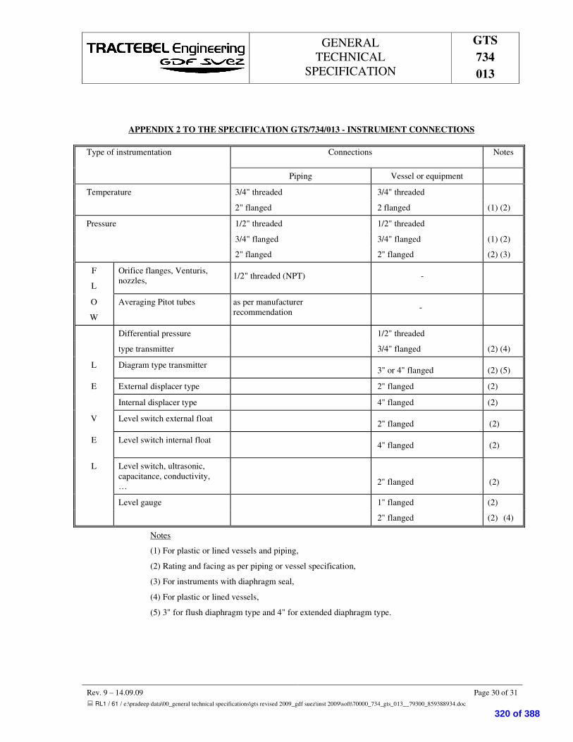
GENERAL TECHNICAL
SPECIFICATION
GTS 734 013
Rev. 9 – 14.09.09 Page 30 of 31 � RL1 / 61 / e:\pradeep data\00_general technical specifications\gts revised 2009_gdf suez\inst 2009\soft\70000_734_gts_013__79300_859388934.doc
APPENDIX 2 TO THE SPECIFICATION GTS/734/013 - INSTRUMENT CONNECTIONS
Type of instrumentation Connections Notes
Piping Vessel or equipment
Temperature 3/4" threaded 3/4" threaded
2" flanged 2 flanged (1) (2)
Pressure 1/2" threaded 1/2" threaded
3/4" flanged 3/4" flanged (1) (2)
2" flanged 2" flanged (2) (3)
F
L
Orifice flanges, Venturis, nozzles, 1/2" threaded (NPT) -
O
W
Averaging Pitot tubes as per manufacturer recommendation -
Differential pressure 1/2" threaded
type transmitter 3/4" flanged (2) (4)
L Diagram type transmitter 3" or 4" flanged (2) (5)
E External displacer type 2" flanged (2)
Internal displacer type 4" flanged (2)
V Level switch external float 2" flanged (2)
E
Level switch internal float 4" flanged (2)
L Level switch, ultrasonic, capacitance, conductivity, …
2" flanged (2)
Level gauge 1" flanged (2)
2" flanged (2) (4)
Notes
(1) For plastic or lined vessels and piping,
(2) Rating and facing as per piping or vessel specification,
(3) For instruments with diaphragm seal,
(4) For plastic or lined vessels,
(5) 3" for flush diaphragm type and 4" for extended diaphragm type.
320 of 388

GENERAL TECHNICAL
SPECIFICATION
GTS 734 013
Rev. 9 – 14.09.09 Page 31 of 31 � RL1 / 61 / e:\pradeep data\00_general technical specifications\gts revised 2009_gdf suez\inst 2009\soft\70000_734_gts_013__79300_859388934.doc
APPENDIX 3 TO THE SPECIFICATION GTS/734/013 - LOCATION OF FLOW AND PRESSURE
INSTRUMENT CONNECTIONS
ON HORIZONTAL PIPES
Fluid Location of instrument connections Notes
Gas Vertically upward (2)
Steam Horizontally
Liquid From horizontal centre line down to 45° below horizontal centre line
(1) (2)
Notes
(1) For slurry and corrosion service, connections must be on top of piping.
(2) For cryogenic gas and liquid, see Piping Standard Assemblies.
S S S
321 of 388

GENERAL TECHNICAL
SPECIFICATION
70000 734
GTS/040
����������������� ���������������
������������
5 14.09.09 Logo Changed AS SD KNC
4 27.03.08 Logo Changed AS NS KNC
3 30.04.07 Logo Changed AR PKS KNC
2 12/09/01 Electronic controllers included CW1 MRY DNP
1 31/08/01 First issue CW1 MRYP DNP
Rev. Date Subject of revision Author Checked Approved
322 of 388
GENERAL TECHNICAL
SPECIFICATION
70000 734
GTS/040
Rev. 5 – 14.09.09 Page I of II
����������������
�
��� �������������������������������������������������������������������������������������������������������������������������������������������������
�� ���� �����������������������������������������������������������������������������������������������������������������������������������������
����� ��������������������������������������������������������������������������������������������������������������������������������������������
����� �� ��!���"� "# �"� ���$"%���&'�#�(������������������������������������������������������������������������������������������
��)�� ��*��+�"� ,�#��--#�*"%��������������������������������������������������������������������������������������������������������������
��� �������������������� �������������������������������������������������������������������������������������������������������
��� ���� ����������������������������������������������������������������������������������������������������������������������������
��� ������������������� ���� ����������������������������������������������������������������������
��� ��������������������������������������������������������������������������������������������������������������������������
.���� ����#�%��/���(�������������������������������������������������������������������������������������������������������������������������0�
.���� �"��#���#1'������������������������������������������������������������������������������������������������������������������������������0�
.�)�� �"%1'%"���������2���'�/��������������������������������������������������������������������������������������������������������������.�
.�3�� �'�%4�"���'--%/�����2�����%�#�����������������������������������������������������������������������������������������������������.�
.�0�� ���%�#��������������������������������������������������������������������������������������������������������������������������������������.�
.�.�� ��#1'%"���$��'(-����������������������������������������������������������������������������������������������������������������������5�
��� ����������������������������������������������������������������������������������������������������������������������������������
�� �����������������������������������������������������������������������������������������������������������������������������������������
!�� ��������������"�#�$%%&'(�)*+*%,������������������������������������������������������������������������������������������������ �
6���� ��-��$��������������������������������������������������������������������������������������������������������������������������������������7�
6���� ����#'(���"����������������������������������������������������������������������������������������������������������������������������7�
�-��� ��������������������������������������������������������������������������������������������������������������������������� �
����� �����������������������������������������������������������������������������������������������������������������������������������������!�
���� ���������������������������������������������������������������������������������������������������������������������������!�
������ ����#"%�����������������������������������������������������������������������������������������������������������������������������������6�
323 of 388

GENERAL TECHNICAL
SPECIFICATION
70000 734
GTS/040
Rev. 5 – 14.09.09 Page II of II
������ �"%*"��8��$������������������������������������������������������������������������������������������������������������������������������6�
��������������� ������������������������������������������������������������������������������������������������������������������!�
�)���� ����������2��9�12"��1"%��"#��:�"�;���������������������������������������������������������������������������������������������6�
�)���� �/���(�������"� ����-�1����������������������������������������������������������������������������������������������������������6�
�)�)�� ��4�������������������������������������������������������������������������������������������������������������������������������������6�
����� � ������������������������������������������������������������������������������������������������������������������������������������!�
�3���� 9"��#�"%��'"#"�����������������������������������������������������������������������������������������������������������������������6�
�3���� ��#��#("�1���'"#"����������������������������������������������������������������������������������������������������������������<�
�3�)�� �*"�%"=�%��/������������������������������������������������������������������������������������������������������������������������������<�
�������� � ������������� ���������������������������������������������������������������������������������������������������-�
���������������������������������������������������������������������������������������������������������������������������������������������-�
S S S
324 of 388

GENERAL TECHNICAL
SPECIFICATION
70000 734
GTS/040
Rev. 5 –14.09.09 Page 1 of 10
�� ������
This specification covers the basic and technical requirements for the design, the selection, the requisitioning and the installation for the gas heating & pressure letdown skid as well as the associated boilers skid.
The skids will consist of two identical trains (phase 1) with provision for a future Tie-in of a third train (phase2).
� ���� ��
���� ������������
Subject to the requirements of the context, the terms (hereafter listed in alphabetical order) used in this specification are given the following meaning :
AGREEMENT Designates the agreement concluded between the CLIENT and the CONTRACTOR, under which the latter undertakes to the former the GOODS and/or SERVICES according to the stipulations which are agreed and specified in the form of an order
CLIENT Designates the purchaser of the GOODS and/or SERVICES which are the subject of the AGREEMENT.
CONTRACTOR Designates the individual or legal entity with whom the order has been concluded by the CLIENT. The term "CONTRACTOR" may be used indifferently for a supplier, a manufacturer, an erection contractor, etc.
DAYS - WEEKS - MONTHS Specify the number of calendar days, weeks or months and not of working days, weeks or months.
ENGINEER Designates TRACTEBEL ENGINEERS & CONSTRUCTORS PVT. LTD. and its associates, if any, to which the CLIENT has entrusted various tasks in relation with the carrying out of his PROJECT.
GOODS and/or SERVICES Designate, depending on the case, all or part of the drawings or documents, substances, materials, materiel, equipment, structures, plant, tools, machinery, ... to be studied , designed, manufactured, supplied, erected, built, assembled, adapted, arranged or put into service by the CONTRACTOR under the agreement, including all the studies, tasks, works and services specified by the order. The terms GOODS or SERVICES may by indifferently used one for the other as required by the context.
PROJECT Designates the aggregate of GOODS and/or SERVICES to be provided by one or more CONTRACTORS.
325 of 388

GENERAL TECHNICAL
SPECIFICATION
70000 734
GTS/040
Rev. 5 –14.09.09 Page 2 of 10
���� �� ��!���"� "# �"� ���$"%���&'�#�(�����
The design, construction, materials, testing of the skid shall be in accordance with the codes and standards mentioned in the present specification and in other applicable General Technical Specification (GTS) and with the codes, standards and legal requirements listed in the Particular Technical Specifications (PTS) for the PROJECT.
In case of contradiction between the GTS and PTS the PTS will be always prevalent.
��)� ��*��+�"� ,�#��--#�*"%�
Whenever CLIENT and/or ENGINEER review and/or approval is requested on a document to be submitted by the CONTRACTOR or before an action is implemented by the CONTRACTOR, such review and/or approval shall always be requested in writing by the CONTRACTOR to the CLIENT and/or the ENGINEER before any action subject of this review and/or approval is taken.
CLIENT and/or ENGINEER approval shall always be given in writing.
�� �������������������� �����
Instrument symbols and identification on P&I Diagrams shall be in accordance with the specification GTS/734/003 "Instrumentation symbols and identification"'.
�� ���� ��������������
The supply of the gas pressure letdown skid shall cover as a minimum the design, manufacture, assembly and test of the gas heating & pressure letdown and boilers skids and safety associated devices. The package shall also include all the necessary control equipment with enclosures suitable for the working environment. Information from both skids shall be transmitted by hardwiring to the SCADA system.
�� ������������������� ���� ����������������������������
Process data for the gas heating & pressure letdown skid are given in the Particular Technical Specification for the project.
The gas heating & pressure letdown skid shall include the necessary equipment to perform safely the operation for which it is designed. It shall be equipped with, but not limited to (see also the relevant PID):
� one process connection at inlet.
� one process connection at outlet.
For each train
� One manual actuated inlet double block and bleed integrated isolation valve, (the diameter size is given on the relevant PID )
This valve shall be equipped with a by-pass for line pressurisation this by-pass shall be composed of one 2" isolation valve and one manually operated control valve.
326 of 388

GENERAL TECHNICAL
SPECIFICATION
70000 734
GTS/040
Rev. 5 –14.09.09 Page 3 of 10
� one water-gas heat exchanger:
The construction of the exchangers will be of steel following section VII (Unfired Pressure Vessels) code ASME "Boiler and Pressure Vessels Code" last edition.
The heat exchanger will satisfy the following specifications:
� the materials used for the construction of the exchanger except for the tube bundle must satisfy the impact tests at - 20°C;
� delivered with a 3.1.B. certificate, in compliance with DIN 50049 or equivalent;
� A relief valve will be placed on the water circuit side . This relief valve routed to safe location, is designed to prevent any pressure increase in case of tube rupture.
� The heater shall be a shell and tube heat exchanger designed and constructed according to TEMA B, ASME VIII div1. The calculation note must be approved by the third authority.
� Alarm to be provided at the maximum water circuit pressure;
� Heater shell in CS shall be foreseen with a corrosion allowance of 3 mm;
� At the top of the exchanger a small valve will be installed for air purging.
� one temperature gauge/thermowell;
� one pressure gauge;
� one slam shut-off valve, with the following characteristics:
� this valve shall be pneumatically actuated and (direct spring type) of fail closed type;
� this valve shall be equipped with limit switches to indicate its position ; these positions shall be transmitted to the SCADA system.
� RF flanged;
� this valve shall be equipped with a manual reset and opening device;
� manual trip must be possible;
� actuation possible by maximum and minimum pressure;
� the seat leakage specification shall be class 6 according to ANSI B16.104;
� the accuracy of the trip settings shall be +/- 2%;
� the setting range shall be :
� for the maximum set point, 90 to 150% of the maximum outlet pressure;
� for the minimum set point, 10 to 40% of the maximum outlet pressure.
327 of 388

GENERAL TECHNICAL
SPECIFICATION
70000 734
GTS/040
Rev. 5 –14.09.09 Page 4 of 10
� "monitor" valve
� this valve shall be pneumatically actuated and of fail closed type;
� RF flanged;
� the valve shall control the outlet pressure;
� the pressure control shall made locally by an independent pneumatic controller .
� the maximal increase of the downstream pressure or "closing overpressure" shall not exceed 5% of the set pressure,
� it shall be possible to modify the nominal flow by changing easily the internal restriction pieces of the valves,
� the control range shall be from 40 to 120 % of the maximal outlet pressure,
� the accuracy of the regulated outlet pressure shall be +/- 2% of the set pressure for a flow varying from 3 to 100%,
� the seat leakage specification shall be class 4 according to ANSI B16.104;
� "regulator" flow/pressure valve
� this valve shall be pneumatically actuated and of fail open type;
� RF flanged;
� the valves shall control the outlet pressure and the flow when this one will reach the maximum allowable value;
� the pressure control and the override control by the flow shall be realised through electronic PID controllers mounted in the local panel .
� the maximal increase of the downstream pressure or "closing overpressure" shall not exceed 5% of the set pressure,
� it shall be possible to modify the nominal flow by changing easily the internal restriction pieces of the valves,
� the control range shall be from 40 to 120 % of the maximal outlet pressure,
� the accuracy of the regulated outlet pressure shall be +/- 2% of the set pressure for a flow varying from 3 to 100%,
� the seat leakage specification shall be class 4 according to ANSI B16.104;
� Two indicating pressure transmitters; each one will be dedicated to the active control valve and the monitor control valve;
� All signals shall be made available on terminals in the local panel for hardwired connexion to the SCADA system.
328 of 388
GENERAL TECHNICAL
SPECIFICATION
70000 734
GTS/040
Rev. 5 –14.09.09 Page 5 of 10
� one temperature gauge/ thermowell;
� one cold vent connection equipped with one isolating 2" valve and one manual throttling 2" valve;
� one drain connection with one isolating valve and one manual throttling valve.
� one manual activated outlet double block and bleed integrated isolation valve, (the diameter size is given on the relevant PID ).
� The noise level should not exceed 85 dbA as measured 1 m downstream the valve or within 1 m distance from the pipe outside diameter..
�� ��������������������������������
The heating of the gas before the let-down will be achieved through a heat exchanger (water/gas) placed on the line of let-down. The warm water is reheated after exchange by independent boilers. (See the typical PID for Central heating package).
.��� ����#�%��/���(�
The gas temperature control system shall be supplied by the VENDOR. The control system shall control the outlet gas temperature within the limits indicated in the process data of the PTS. The system shall be shut down when the outlet gas temperature reaches 50°C.
Typically (It may vary between package manufacturer) two control systems in cascade will achieve a stable gas temperature at the outlet of the station:
� The gas supply to the boilers regulates a constant temperature of the water circuit at the outlet of the boilers;
� The three-way valves on the water circuit at the heat exchangers inlet regulate the temperature of the gas after let-down. Part of the flow is sent to the heat exchangers to heat the gas, part of the flow is by-passed.
.��� �"��#���#1'���
The heat exchangers are inter-connected so that it is always possible to feed simultaneously or separately each exchanger.
The duty of each boiler will be calculated in such way that in the event of shut-down of one boiler, the other boiler can take over and assure that the heat-exchangers remain supplied:
� Initially (phase 1), 2 boilers with a design capacity of 100 % of the duty necessary for the exchanger supply will be provided;
� In a later stage (phase 2) ,a third and fourth boiler will be added to comply with the pressure increase at inlet of the Station.
A pumps set (one + one 100% spare in phase 1) will guarantee a permanent circulation of the water in the circuit. One indicating pressure transmitter will be provided with an alarm actuated (and sent to the SCADA) in case of high pressure detection what may be caused by a gas leak in the exchanger.
329 of 388

GENERAL TECHNICAL
SPECIFICATION
70000 734
GTS/040
Rev. 5 –14.09.09 Page 6 of 10
If necessary, water make-up will realised via the water injection fitting. The water will be always provided with an anti-corrosion inhibitor.
An expansion drum connected to the water circuit will limit any pressure increase due to the thermal variations of the water.
.�)� �"%1'%"���������2���'�/�
� the duty of the heating package shall be calculated in such a way that, at nominal capacity, the temperature of gas after expansion can never drop below 10°C. The PTS gives the other eventual requirements;
� The accuracy of the temperature control will be such that the temperature compared to the set point temperature cannot vary by more than 2°C ;
.�3� �'�%4�"���'--%/�����2�����%�#���
The gas will be off-taken at the outlet of the station (one manometer).
The gas will be fed to the boilers using the following installation.
Two (one + 100% spare) feed lines will be provided. Each one will include:
� a block valve;
� a safety valve operating at "High-high" pressure installed on the inlet collector.
� a filter;
� a pressure regulator;
� a complementary safety valve;
As an option, a small meter will be installed for the control of the consumption of the boiler.
.�0� ���%�#��
Two boilers shall be supplied each having 100 % of the required design thermal capacity. The boiler will produce hot water at a temperature of 90°C typically.
The boiler will use natural gas taken downstream the pressure reduction station. Complementary pressure reducing valves shall be supplied by the vendor to feed burners at the required pressure (see §6.4.).
Safety devices will be provided in the regulating system of the boiler, in order to control the closing of the feeding circuit of the gas boiler in case:
� of extinction of the pilot flame;
� of a too high gas temperature at the outlet of the heat exchanger (this temperature may not exceed 50°C).
� of a too high temperature of the coolant;
330 of 388

GENERAL TECHNICAL
SPECIFICATION
70000 734
GTS/040
Rev. 5 –14.09.09 Page 7 of 10
� of low level of the coolant.
These devices moreover will be supplemented by a general alarm and sound signal connected to the SCADA.
The valve assembly around the boilers is designed so that an intervention on the boilers (maintenance, disassembling...) does not require the shut-down of the station.
The chimneys of the boilers will be provided with a 1/2" fitting for gas composition analysis.
Boilers data sheets attached to the MR shall be filled in by VENDOR at bid stage.
The boiler design pressure shall be minimum 6 barg at a design temperature of 100°C.
.�.� ��#1'%"���$��'(-��
The two circulating pumps shall be DIN or ISO standard pumps. In-line pumps are acceptable.
For non in-line pump, the VENDOR shall supply the base plate in carbon steel, the electrical motor, the coupling and the coupling guard. The material shall be supplied with a CE certificate.
Stand-by connections for phase 2 will be foreseen.
�� �������������������
The piping requirements must be in accordance with the attached piping classes specification.
� ����������������
The scope of the CONTRACTOR includes :
� detailed drawings and calculations;
� assistance to third authority examination;
� design fabrication, assembly and testing of the complete skid including but not limited to :
� inlet/outlet double block and bleed valves;
� heaters
� flow/pressure control valves;
� safety shut-off valves;
� electronic controllers
� instrumentation ,skid and local panel mounted;
� connection to venting system.
331 of 388

GENERAL TECHNICAL
SPECIFICATION
70000 734
GTS/040
Rev. 5 –14.09.09 Page 8 of 10
� junction boxes for connection to the local panel (different junction boxes shall be provided for analogue signals, for digital input signals and for digital output signals);
� spare parts for start-up operations and two years operation;
� mechanical tests;
� material certificates;
� non destructive tests;
� performance tests;
� preparation and application of shop painting.
!� ��������������"�#�$%%&'(�)*+*%,�
6��� ��-��$�
The battery limit connections shall be as follows :
� gas inlet skid : according PID;
� gas outlet skid : according PID;
� Boilers skid water inlet/outlet according to PID;
� gas vent to safe location;
� drain collectors.
6��� ����#'(���"�����
� Junction boxes for connections to the local panel, signals shall be separated as follows :
� analogue signals;
� digital inputs;
� digital outputs.
�-� � ��������������������
All process instruments shall be clearly identified by locally fixed traffolite labels, showing their tag or loop numbers.
All instruments panels and junction boxes shall be clearly identified by traffolite labels.
Labels and their fixings should be durable to the site environmental conditions.
332 of 388

GENERAL TECHNICAL
SPECIFICATION
70000 734
GTS/040
Rev. 5 –14.09.09 Page 9 of 10
��� � �����
All components of the package shall be clearly marked with a stainless steel plate (to be submitted for approval) showing main characteristics and item numbers which shall comply with here attached standard.
�� � �������������������
����� ����#"%�
Painting of equipment shall be carried out in works or at site as appropriate. The system of painting and finishing shall be of approved colour and quality.
����� �"%*"��8��$�
Galvanizing shall be hot dip galvanising in accordance with BS 729, "Hot Dip Galvanised Coatings on Iron and Steel Articles". Bolts, nuts and washers together with other threaded components used as Fasteners shall be finished with a Centrifuged Galvanised coating in accordance with this Standard.
All drilling, punching, stamping, cutting and bending of parts together with welding and removal of burrs shall be completed before articles are galvanised in accordance with BS729.
��� ����������� ����������
�)��� ����������2��9�12"��1"%��"#��:�"�;�
A hydrostatic test shall be performed on the station at 1.5 times the design pressure.
All welds shall be 100 % tested by radiography before hydrostatic tests.
�)��� �/���(�������"� ����-�1�����
The test shall be conducted at the manufacturer's factory, according manufacturer procedure.
The tests shall include the operational check of the of the control and on/off valves and of the safety system.
All in/out signals will be tested starting from junction boxes and panels.
�)�)� ��4�����������
This test shall be performed on the process to check the performance of the system.
��� � � ������
�3��� 9"��#�"%��'"#"�����
The CONTRACTOR is responsible for the quality of materials and workmanship included in the manufactured equipment.
333 of 388
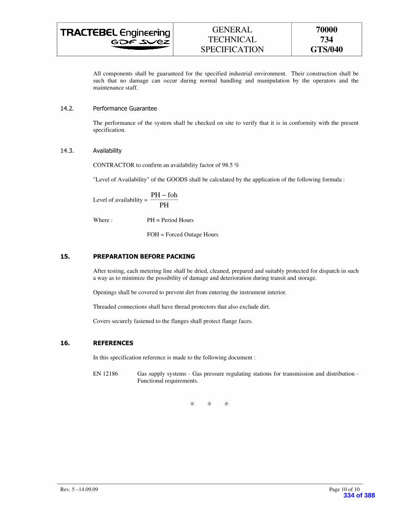
GENERAL TECHNICAL
SPECIFICATION
70000 734
GTS/040
Rev. 5 –14.09.09 Page 10 of 10
All components shall be guaranteed for the specified industrial environment. Their construction shall be such that no damage can occur during normal handling and manipulation by the operators and the maintenance staff.
�3��� ��#��#("�1���'"#"�����
The performance of the system shall be checked on site to verify that it is in conformity with the present specification.
�3�)� �*"�%"=�%��/�
CONTRACTOR to confirm an availability factor of 98.5 %
"Level of Availability" of the GOODS shall be calculated by the application of the following formula :
Level of availability = PH
fohPH −
Where : PH = Period Hours
FOH = Forced Outage Hours
��� ���� � ������������� �����
After testing, each metering line shall be dried, cleaned, prepared and suitably protected for dispatch in such a way as to minimize the possibility of damage and deterioration during transit and storage.
Openings shall be covered to prevent dirt from entering the instrument interior.
Threaded connections shall have thread protectors that also exclude dirt.
Covers securely fastened to the flanges shall protect flange faces.
��� �����������
In this specification reference is made to the following document :
EN 12186 Gas supply systems - Gas pressure regulating stations for transmission and distribution - Functional requirements.
S S S
334 of 388

GTS – FILTRATION SKID
70000 740
GTS/006
������������������������� ����������
����
��������������
5 14.09.09 Generally Revised AS SD KNC
4 14.08.08 Generally Revised VS SD KNC
3 27.03.08 Logo Changed AS NS KNC
2 30.04.07 Logo Changed AR PKS KNC
1 08/11/01 First issue GRD MRY DKB
Rev. Date Subject of revision Author Checked Approved
335 of 388

GTS – FILTRATION SKID
70000 740
GTS/006
Rev. 5 – 14.09.09 Page I of II
������������������
�� ������������������������������������������������������������������������������������������������������������������������������������� �
��� �������������������������������������������������������������������������������������������������������������������������������������� �
����� ��!�!�!��������������������������������������������������������������������������������������������������������������������������������
����� �� ��"����� �# ��$���%���#�&'!#�����������������������������������������������������������������������������������
��(�� #�)!�*�$��++#�)�������������������������������������������������������������������������������������������������������������������
��� ����������������������������������������������������������������������������������������������������������������������������������������
(���� !������������!���������������������������������������������������������������������������������������������������������������������
(���� �'������������!������������������������������������������������������������������������������������������������������������������
(�(�� !�����)��)������������������������������������������������������������������������������������������������������������������������������
(�,�� �'�����)��)����������������������������������������������������������������������������������������������������������������������������
(�-�� ��'�.!�%��������!���������������������������������������������������������������������������������������������������������������
(�/�� �������!�%��!���#������������������������������������������������������������������������������������������������������������������
(�0�� !���#'������!�������������������������������������������������������������������������������������������������������������������(�
(�1�� �����#!�!�2���������������������������������������������������������������������������������������������������������������������������(�
(�3�� �4! ��������2�����������������������������������������������������������������������������������������������������������������������(�
��� �����������������������������������������������������������������������������������������������������������������������������������
��� ������������������������������������������������������������������������������������������������������������������
��� ����������������������������������������������������������������������������������������������������������������������������������������
/���� +!+!�%������������������������������������������������������������������������������������������������������������������������������������,�
/���� !���#'������!�������������������������������������������������������������������������������������������������������������������-�
��� ��������������������������������������������������������������������������������������������������������������������������������������������
��� ��������������������������������������������������������������������������������������������������������������������������������������������
��� ��������������������������������������������������������������������������������������������������������������������������������������������
3���� %���#�����������������������������������������������������������������������������������������������������������������������������������-�
3���� %��)��!5!�%��������������������������������������������������������������������������������������������������������������������������-�
336 of 388
GTS – FILTRATION SKID
70000 740
GTS/006
Rev. 5 – 14.09.09 Page II of II
�����������������������������������������������������������������������������������������������������������������������������
�6���� �����#2�����+��������������������������������������������������������������������������������������������������������������/�
�6���� �!���+�#��#������������������������������������������������������������������������������������������������������������������/�
������������������������������������������������������������������������������������������������������������������������������������������
������ ����#!���%'�#������������������������������������������������������������������������������������������������������������������/�
������ +�#��#������%'�#�����������������������������������������������������������������������������������������������������������0�
���(�� �)�!���!�!�2��������������������������������������������������������������������������������������������������������������������������0�
������������������������������������������������������������������������������������������������������������������������������������������������
��������������������������������������������������������������������������������������������������������������������������������������������
S S S
337 of 388

GTS – FILTRATION SKID
70000 740
GTS/006
Rev. 5 – 14.09.09 Page 1 of 7
� ������������
The present GTS (General Technical Specification) deals with the basic technical requirements for the design, procurement and erection of the filtration skid.
�� �����������
���� ��!�!�!����
AGREEMENT Decision concluded between the CLIENT and the CONTRACTOR by which the CONTRACTOR will supply to the CLIENT some GOODS and/or SERVICES according to the stipulations specified in the form of an order.
CLIENT Purchaser of the GOODS and/or SERVICES which are specified in an AGREEMENT.
CONTRACTOR Legal entity having concluded an AGREEMENT with the CLIENT. The term "CONTRACTOR" may be used indifferently for a supplier, a manufacturer, an erection contractor, etc.
DAYS WEEKS MONTHS
Number of calendar days, weeks or months.
ENGINEER TRACTEBEL ENGINEERS & CONSTRUCTORS PVT. LTD. as being involved in this PROJECT.
GOODS SERVICES
All or parts of the drawings, documents, materials, equipments, tools, to be designed, manufactured, supplied, erected, commissioned by the CONTRACTOR according to an AGREEMENT.
PROJECT All the GOODS and/or SERVICES to be provided by one or several CONTRACTORS.
���� �� ��"����� �# ��$���%���#�&'!#�������
The materials, design, construction and testing of the filtration skid shall be in accordance with the codes, standards and legal requirements mentioned in the present General Technical Specification (GTS) and in the Particular Technical Specifications (PTS) of this PROJECT.
The PTS will always be prevalent in case of contradiction between GTS and PTS.
��(� #�)!�*�$��++#�)���
Whenever CLIENT and/or ENGINEER review and/or approval is requested for a document submitted by the CONTRACTOR or before an action is implemented by the CONTRACTOR, such review and/or approval shall always be requested in writing by the CONTRACTOR to the CLIENT and/or the ENGINEER before any action is taken related to this review and/or approval.
CLIENT and/or ENGINEER approval shall always be given in writing.
338 of 388

GTS – FILTRATION SKID
70000 740
GTS/006
Rev. 5 – 14.09.09 Page 2 of 7
�� ����������
The skid consists of two identical trains with tie-in connections for a future third train.
The flow sheet annexed in Appendix 1 describes the filtration skid ; the main items are listed hereafter.
FOR THE SKID
(��� !������������!���
� one process inlet connection;
� thermometer, manometer and pressure transmitter.
(��� �'������������!���
� one process outlet connection
FOR EACH TRAIN
(�(� !�����)��)��
� one manual IDB valve (Internal Double Block & Bleed) bypassed, for pressure balancing, with 2 manual valves in series (one block valve and one throttling valve) ; the IDB valve is provided with open and closed limit switches.
(�,� �'�����)��)��
� one manual IDB valve (Internal Double Block & Bleed).
(�-� ��'�.!�%��������!���
� two manual valves in series (one block valve and one throttling valve).
(�/� �������!�%��!���#�
One coalescing filter, made of carbon steel, designed according to the ASME VIII Div. 1 code, with the following requirements :
� the coalescing filter is designed to remove the liquid and solid particles above 5 microns ;
� an impact test @ -20°C is required for the material of the shell and the heads ;
� all the materials are to be delivered with a 3.1.B certificate (DIN 50049) ;
� a relief valve is fit on the shell side ;
� the mechanical calculation note of the coalescing filter is to be approved by a Third Authority ;
339 of 388
GTS – FILTRATION SKID
70000 740
GTS/006
Rev. 5 – 14.09.09 Page 3 of 7
� shell and heads material thickness has to include a 3 mm corrosion allowance ;
� typically, the filter is provided with level gage and transmitter, manometer and pressure drop transmitter, vent valves (2 manual valves in series, one block valve and one throttling valve) and drain valves (2 manual valves in series, one block valve and one throttling valve).
(�0� !���#'������!���
All the instrumentation indicated on the flow sheet attached in Appendix 1 will be provided by the VENDOR.
The instruments will be suitable for an hazardous area classified “zone 2 - II A T3 ; they will be wired up to junction boxes suitable for that classified area.
All the electrical materials will be weatherproof for outdoor installation (minimum IP 55) ; for the safety protection (hazardous area), they will be intrinsically safe EEx(ia) or (ib) or explosion-proof EEx(d).
(�1� �����#!�!�2�
The filtration skid will be equipped with :
� all the required electrical materials ;
� the power/control cabinets ;
� the cabling and wiring inside the battery limits ;
� the earthing inside the battery limits ;
The electrical materials will comply with the IEC standards and all the applicable local regulations.
The electrical materials will be suitable for an hazardous area classified “zone 2 - II A T3 ; they will be wired up to junction boxes suitable for that classified area.
All the electrical materials will be weatherproof for outdoor installation (minimum IP 55) ; for the safety protection (hazardous area), they will be intrinsically safe EEx(ia) or (ib) or explosion-proof EEx(d).
The available power supply is 440 V, 3 ph, 50 Hz, 4 wire, neutral solidly earthed.
The power/control panels/cabinets will be equipped with all the required protections and control devices.
The cables will enter the power/control panels, junction boxes, instruments, cabinets from the bottom.
(�3� �4! ��������2�
All the above equipment will be assembled on a common skid equipped with lifting and earthing lugs.
�� �����������
The CONTRACTOR’s scope of supply is :
340 of 388

GTS – FILTRATION SKID
70000 740
GTS/006
Rev. 5 – 14.09.09 Page 4 of 7
� detailed drawings and calculations ;
� assistance to Third Authority examination ;
� design, fabrication, assembly and testing of the complete skid including but not limited to :
� inlet/outlet double block and bleed valves ;
� coalescing filters ;
� electronic controllers ;
� instrumentation, skid and local panel mounted ;
� connection to venting system ;
� junction boxes for connecting into the local panel (separated junction boxes to be provided for analogue signals, digital input signals and digital output signals) ;
� spare parts for commissioning and two years operation ;
� mechanical tests ;
� material certificates ;
� non destructive tests ;
� shop painting.
�� �����������������������
The next items are excluded from the VENDOR scope of supply :
� civil works (foundations, buildings, etc.) ;
� electrical supply from OWNER substation to skid battery limits ;
� insulation ;
� erection
�� ������������
/��� +!+!�%�
� skid gas inlet : see Appendix 1 ;
� skid gas outlet : see Appendix 1 ;
� gas vents : see Appendix 1 (to safe location) ;
341 of 388

GTS – FILTRATION SKID
70000 740
GTS/006
Rev. 5 – 14.09.09 Page 5 of 7
� drains : see Appendix 1.
/��� !���#'������!���
Junction boxes for connections to the local panel ; the signals shall be separated as follows :
� analogue signals ;
� digital inputs ;
� digital outputs.
�� ���������
All the process instruments will be clearly identified by fixed labels, showing their tag or loop number.
All the instruments panels and junction boxes will be clearly identified by fixed labels.
Labels and their fixings will be durable regarding the site environmental conditions.
�� �������
All the components of the package shall be clearly marked with stainless steel plates (to be submitted for approval) showing the main characteristics and item numbers.
�� ��������
3��� %���#���
Equipments will be painted in workshop or at site, as appropriate. Painting will be of approved colours and quality.
3��� %��)��!5!�%�
Galvanizing will be hot dip according to BS 729 "Hot Dip Galvanised Coatings on Iron and Steel Articles".
Bolts, nuts and washers together with other threaded components used as fasteners will be finished with a centrifuged galvanised coating according to the above standard.
All drilling, punching, stamping, cutting and bending of parts together with welding and removal of burrs shall be completed before articles are galvanised in accordance with BS 729.
� ������������������
Inspection and testing will be performed on all the assemblies and components considering the following list of activities :
342 of 388

GTS – FILTRATION SKID
70000 740
GTS/006
Rev. 5 – 14.09.09 Page 6 of 7
� visual inspection ;
� dimensional checking ;
� pressure testing ;
� non destructive testing ;
� functional/performance testing.
Acceptance criteria will comply with the relevant codes and standards ; if not existing, the VENDOR shall indicate them in a quality control procedure fully approved by a Third Party inspector.
The VENDOR shall indicate a list of inspections and tests with the relevant procedures for being reviewed and approved by the PURCHASER.
Some inspections and tests will be witnessed by the PURCHASER ; they will be proposed by the VENDOR for review and approval by the PURCHASER.
�6��� �����#2�����+������������
The following tests will be performed at the VENDOR shop.
� Hydrostatic test
All the pressure containing parts (casing, filters, piping and valves) will be hydro-tested at 1.5 times the design pressure.
� Leak test
After having been assembled on skid, all the equipment and lines will be pneumatically tested for leaks detection (soap bubbling).
� Instrumentation and control test
A test of the fully integrated system will be performed at the work shop ; logging data will be issued to demonstrate the performance of the system.
�6��� �!���+�#��#�����������
The VENDOR shall assist the PURCHASER in performing the site performance test which is, basically, a repeat of the instrumentation and control test performed in the VENDOR work shop but with actual signals and not simulated ones.
� ���������
����� ����#!���%'�#������
The CONTRACTOR is responsible for the quality of materials and workmanship included in the manufactured equipment.
343 of 388

GTS – FILTRATION SKID
70000 740
GTS/006
Rev. 5 – 14.09.09 Page 7 of 7
All components shall be guaranteed for the specified industrial environment. Their construction shall be such that no damage can occur during normal handling and manipulation by the operators and the maintenance staff.
����� +�#��#������%'�#������
The performance of the system shall be checked on site to verify that it is in conformity with the present specification.
���(� �)�!���!�!�2�
CONTRACTOR has to confirm an availability factor of 98.5 %
"Level of Availability" of the GOODS is calculated by :
Level of availability = PH
FOHPH − with PH = Period Hours
FOH = Forced Outage Hours
�� �������
After testing, the skid shall be dried, cleaned, prepared and suitably protected for dispatching in such a way to minimize damaging and deterioration during transit and storage.
Openings shall be covered to prevent dirt from entering. Threaded connections shall have thread protectors. Covers securely fastened to the flanges shall protect flange faces.
�� ���������
APPENDIX 1 : FLOW-SHEET FILTRATION SKID
344 of 388
GTS – FILTRATION SKID
70000 740
GTS/006
Rev. 5 – 14.09.09 APPENDIX 1
APPENDIX 1
FLOW-SHEET : FILTRATION SKID
345 of 388

GTS – FILTRATION SKID
70000 740
GTS/006
Rev. 5 – 14.09.09 APPENDIX 1
LG LT
PI
2"
IDB
DPT
2"
IDB
ZSL
ZSH
2"
PT PI TI
LG LT
PI
2"
IDB
DPT
2"IDB
ZSL
ZSH
2"
IDB
IDB
IDB
IDB
PI
PI
ZAL
ZAL
ZAH
ZAH
ZAH
ZAH
ZAL
ZAL
DPI
DPI
DPI
DPI
LI
LILAH
LAH
LI
LI
LAH
LAH
2"
2"
2"
2"2"
TO PRESSURE LET-DOWNSKID
FROM PIGGING STATION
2"2"
2"2"
2"
PAH
PAH
PAL
PAL
DPAH
DPAH
DPAH
DPAH
BA
TTE
RY
LIM
IT
BATTERY LIMIT
�������������
FLOW-SHEET
XX
XX
XX
LOCALLY MOUNTED INSTRUMENT
INSTRUMENT ON LOCAL PANEL
SCADA SYSTEM
LEGEND
BATTERY LIMIT
BA
TTE
RY
LIM
IT
346 of 388

GENERAL TECHNICAL
SPECIFICATION
70000 740
GTS/0023
����������������������� ��
���������� ������ �������
5 14.09.09 Logo Changed AS SD KNC
4 30.04.07 Logo Changed AR PKS KNC
3 11/02/04 Updated DFE MRY MRY
2 17/09/03 Updated for stations with one, two or three metering lines DFE MRY MRY
1 05/12/02 First issue DFE MRY LEP
Rev. Date Subject of revision Author Checked Approved
347 of 388

GENERAL TECHNICAL
SPECIFICATION
70000 740
GTS/0023
Rev. 5 – 14.09.09 Page 1 of 2
���������������
� � ����� ���
� � ������� ���
����� �������� ������������������������������������������������������������������������������������������������������������������������������
����� � �����������������������������������������������������������������������������������������������������������
����� ����������� ������ �����������������������������������������������������������������������������������������������������������
����� ��������������������� ����������������������������������������������������������������������������������������������������
� � ������������������������������������������� ���
����� ������������������������������������������������������������������������������������������������������������������������������������������
����� �����������������������������������������������������������������������������������������������������������������������������������
����� �� ������������ ��������������������������������������������������������������������������������������������
����� �������������������������������������������������������������������������������������������������������������������������������� �
� � ������������������ ���
� � ��������������� ���
� � ���������������������������������� ���
���� ������������������������������������������������������������������������������������������������������������������������������������������!�
���� ����������� ������������������������������������������������������������������������������������������������������������������!�
� � ��������������������� � �
� ������������������� � �
"���� ����������������������������������������������������������������������������������������������������������������������������������������"�
"���� �������#�����������������������������������������������������������������������������������������������������������������������������"�
! � ������������������ � �
$���� ����������������������������������������������������������������������������������������������������������������������������������������"�
$���� ������� �����������������������������������������������������������������������������������������������������������������������������$�
$���� ���� �������������������������������������������������������������������������������������������������������������������$�
$���� �������� ���������������������������������������������������������������������������������������������������������������%�
348 of 388

GENERAL TECHNICAL
SPECIFICATION
70000 740
GTS/0023
Rev. 5 – 14.09.09 Page 2 of 2
$�&�� �������� ����������������������������������������������������������������������������������������������������������������������������%�
�" �������������#����� ��"�
�� ���������� ����
������ �����������������������������������������������������������������������������������������������������������������������������������������
������ ��������� ��������������������������������������������������������������������������������������������������������
������ �������������������������������������������������������������������������������������������������������������������������������
������ � ���������� �����������������������������������������������������������������������������������������������������������������
���&�� ���������������������������������������������������������������������������������������������������������������������������������������
�� ���������������������$��� ����
�� �������%������������������� ����
S S S
349 of 388

GENERAL TECHNICAL
SPECIFICATION
70000 740
GTS/0023
Rev. 5 – 14.09.09 Page 1 of 15
� SCOPE
This specification covers the general requirements for the design, manufacture, assembly, calibration, testing, installation and commissioning of natural gas metering stations using ultrasonic flow meters.
� GENERAL
���� DEFINITIONS
Subject to the requirements of the context, the terms (hereafter listed in alphabetical order) used in this specification are given the following meaning
AGREEMENT Designates the agreement concluded between the CLIENT and the CONTRACTOR, under which the latter undertakes to the former the GOODS and/or SERVICES according to the stipulations which are agreed and specified in the form of an order.
CLIENT Designates the purchaser of the GOODS and/or SERVICES which are the subject of the AGREEMENT.
CONTRACTOR Designates the individual or legal entity with whom the order has been concluded by the CLIENT. The term "CONTRACTOR" may be used indifferently for a supplier, a manufacturer, an erection contractor, etc.
DAYS - WEEKS - MONTHS Specify the number of calendar days, weeks or months and not of working days, weeks or months.
ENGINEER Designates the individual or legal entity to which the CLIENT has entrusted various tasks in relation with the carrying out of his PROJECT.
GOODS and or SERVICES Designate, depending on the case, all or part of the drawings or documents, substances, materials, materiel, equipment, structures, plant, tools, machinery, ... to be studied , designed, manufactured, supplied, erected, built, assembled, adapted, arranged or put into service by the CONTRACTOR under the agreement, including all the studies, tasks, works and services specified by the order. The terms GOODS or SERVICES may be indifferently used one for the other as required by the context.
PROJECT Designates the aggregate of GOODS and/or SERVICES to be provided by one or more CONTRACTORS.
���� CODES, STANDARD AND LEGAL REQUIREMENTS
The design, construction, materials, testing of the metering station shall comply with the codes and standards mentioned in the present specification and in other applicable General Technical Specifications (GTS) and with the codes, standards and legal requirements listed in the Particular Technical Specification (PTS) for the PROJECT.
In case of contradiction between the GTS and the PTS the PTS shall always prevail.
350 of 388

GENERAL TECHNICAL
SPECIFICATION
70000 740
GTS/0023
Rev. 5 – 14.09.09 Page 2 of 15
In particular, the following standards are applicable for the gas metering system :
ISO/TR 12765 Measurement of fluid flow in closed conduits - Methods using transit-time ultrasonic flow meters.
ISO 5168 Measurement of fluid flow - Evaluation of uncertainties.
ISO 12213 Natural Gas - Calculation of compression factor.
EN 1776 Gas supply systems - Natural gas measuring stations - Functional requirements
���� REVIEW AND/OR APPROVAL
Whenever CLIENT and/or ENGINEER review and/or approval is requested on a document to be submitted by the CONTRACTOR or before an action is implemented by the CONTRACTOR, such review and/or approval shall always be requested in writing by the CONTRACTOR to the CLIENT and/or the ENGINEER before any action subject of this review and/or approval is taken.
CLIENT and/or ENGINEER approval shall always be given in writing.
���� INSTRUMENT IDENTIFICATION
Instrument symbols and identification on P&I Diagrams shall be in accordance with the General Technical Specification GTS/734/003 "Instrumentation symbols and identification"'.
� DESCRIPTION OF THE NATURAL GAS METERING STATION
���� GENERAL
1) The gas metering station shall be designed with one or, when required, with two or three parallel runs for redundancy and maintainability and shall employ ultrasonic meters for flow quantity measurement. Additionally, temperature and pressure measurement instrumentation shall be provided for each run.
For stations with two or three metering lines, by-pass line(s) shall be provided between the lines in such a way that the metering devices can be operated in series to check one meter against the other one.
2) The gas metering system shall transmit information to a SCADA system.
3) If required, one on-line chromatograph will be provided by others for gas composition analysis. Otherwise the system shall operate from transmitted analysis or from a standard analysis introduced manually and stored in the computer memory.
The gas composition data and other parameters shall be transmitted either directly or, if applicable, through a SCADA system to all flow computers for computation. The CONTRACTOR shall be responsible for interfacing the flow computers with the SCADA system for collection and integrity of those data.
4) The metering station shall be the basis for the sales accounting for the gas. In addition to mass flow, it shall continuously calculate heating value, density, Wobbe index and volume at standard conditions (15°C and 1.01325 bar).
351 of 388

GENERAL TECHNICAL
SPECIFICATION
70000 740
GTS/0023
Rev. 5 – 14.09.09 Page 3 of 15
5) The process data and specific requirements for the gas metering station are given in the PTS for the PROJECT.
The metering station shall be able to measure the flow rates between the specified minimum and maximum flow values.
6) The metering station shall be designed, built, installed and validated in accordance with ISO 5168 and EN 1776.
The gas compressibility factors must be calculated according to ISO 12213-2.
���� METERING LINES
1) Each metering line shall at least include the following equipment.
� One pneumatically actuated, inlet double block and bleed integrated isolation valve, (with open/close proximity switches and solenoid valve for remote operation).
This valve shall be equipped with a by-pass for line pressurisation. This by-pass shall be composed of one isolation valve and one manually operated globe or plug valve.
The CONTRACTOR shall specify the valve stroke time required to avoid unacceptable acceleration torsion in the ultrasonic meters.
� One differential pressure switch which shall be installed across the valve and used to avoid the opening of the valve when the differential pressure is higher than 1 bar.
� One nitrogen injection connection equipped with one isolation valve and one check valve. This line shall be equipped with a quick connection system.
� The ultrasonic flow meter upstream straight pipe with a minimum length of 10D. This pipe shall fulfil the codes and manufacturer standard requirements for such a measuring tube.
� One ultrasonic flow meter with flow and pressure outputs to the flow measurement computer system.
� The ultrasonic flow meter downstream straight pipe with a minimum length of 3D, or 10D when bidirectional flow is required. This pipe shall also fulfil the codes and manufacturer standard requirements for such a measuring tube.
� one 2-wire RTD type temperature transmitter with thermowell,
� one thermowell with local temperature indicator,
� one spare thermowell,
� one connection to the venting system,
� one manually operated outlet double block and bleed integrated isolation valve (with open/close proximity switches).
2) In order to provide proper alignment throughout the metering lines, three knock-out dowel pin holes with different diameters shall be drilled in the ultrasonic flow meter flanges and in the corresponding upstream and downstream meter tube flanges.
352 of 388

GENERAL TECHNICAL
SPECIFICATION
70000 740
GTS/0023
Rev. 5 – 14.09.09 Page 4 of 15
The internal diameter of the meter tubes shall be identical to the internal diameter of the ultrasonic flow meters.
The inside surface of the meter tubes shall be as smooth as possible and shall be clean and free from incrustations, pitting and deposits.
The circularity of the meter tubes shall comply with ISO requirements.
3) Each metering line shall be thermally insulated, including the ultrasonic flow meter, and the transmitters shall be installed in a protective enclosure in order to minimize the environmental temperature effects on the overall accuracy of the metering system.
4) The ultrasonic flow meters shall be calibrated in an accredited laboratory. If possible, complete lines shall be checked. If not, the ultrasonic flow meter shall be calibrated with its upstream length. The calibration shall be done on 5 points for each flow meter.
5) All instrument signals shall be wired up to the skid edge to junction boxes. Separate types of junction boxes must be provided for analogue signals, digital inputs, digital outputs, frequencies or pulses, etc. Furthermore, distinct junction boxes must be used for distinct electrical safety protection system like explosion-proof (EExd), intrinsic safety (EExi), increased safety (EExe).
6) In general analogue signals and digital inputs are of the intrinsically safe type. The signals to the solenoid valves are of the increased safety type (24 V DC).
7) The accuracy of the pressure transmitters shall be ± 0.1 % or better in the range 0-50 barg. The accuracy of the temperature transmitters shall be ± 0.1 °C or better for the range 0-40°C.
���� FLOW MEASUREMENT COMPUTER SYSTEM
1) Each metering line shall have a dedicated flow computer connected to the ultrasonic flow meter and to the associated pressure and temperature transmitters. The flow computer shall calculate gas flow rate and totalize the flowing quantities.
The flow computers shall be installed in a cabinet in a separate room,
2) The flow computers shall communicate directly or indirectly with
� an on-line gas chromatograph (if required),
� the transmitters on the metering line,
� the valves in the metering lines,
� an operator console (with a CRT monitor and a keyboard),
� a report printer,
� a SCADA system.
3) The flow computers shall
� collect data from each metering line,
� receive the gas composition from the gas chromatograph, if provided, otherwise they shall operate from transmitted analysis or from a standard analysis introduced manually and stored in the computer memory,
353 of 388

GENERAL TECHNICAL
SPECIFICATION
70000 740
GTS/0023
Rev. 5 – 14.09.09 Page 5 of 15
� calculate the total instantaneous volume and energy flow-rate,
� provide flow totalizing for hourly, daily, weekly, monthly, etc. quantities; the schedule of issue of these values must be configurable according to the CLIENT's requirements,
� handle all alarms generated by the metering system,
� drive the operator console and the report printer,
� retransmit signals to a SCADA system.
4) The operator console shall
� display all information associated with the metering system (process data, flowrates, valve status, alarms, ... ),
� allow programming and configuration of the flow metering computer system.
5) The metering computer system shall generate and print out reports that shall be designed according to CLIENT's requests. They must at least include the following data:
� metering lines in operation,
� metering line un-corrected flow, corrected flow, pressure and temperature, (instantaneous, average, minimum, maximum over the period of time),
� totalized mass, volume and energy flow (per metering line and total),
� calculation parameters.
Reports may also be printed on operator's request.
6) The flow computers shall be configurable type rather than programmable type.
7) The flow computers shall be equipped with data storage registering all synchronized individual data provided by the measuring devices before any correction is made by the computer together with all results of calculation.
Storage capacity shall allow for data to be stored for at least one calendar month. Each flow computer shall have provision to input data manually (such as super compressibility factor, gas mean heating value, etc.) in case of failure of data transmission from the gas chromatograph to the flow computers.
8) The flow computers shall be equipped with internal battery back-up preserving the RAM memory for at least 30 days when no power is available anymore.
9) Each individual flow computer with related logic and software shall be approved and certified for custody transfer by local authorities or by foreign recognized authorities.
10) The flow computers shall have all the algorithms to perform the functions required in accordance with the standards or codes referred to in this specification. The CONTRACTOR shall indicate the algorithms available. The detail algorithms will be finalized during execution of the PROJECT.
11) Each flow computer shall include in its software the ultrasonic flow meter "error curves" as the result from ultrasonic flow meter calibration and perform compensation as required.
12) The flow computer system shall transmit to a SCADA system all information regarding the operation of the metering lines as well as the instantaneous values of pressures, temperatures and corrected flows and totalized corrected flows
354 of 388

GENERAL TECHNICAL
SPECIFICATION
70000 740
GTS/0023
Rev. 5 – 14.09.09 Page 6 of 15
13) The mass flow in each meter tube shall be calculated from continuous signals for gas composition in flowing conditions, flow, temperature and pressure.
14) The volume flow at standard conditions shall be calculated from mass flow and reference density as determined by the gas chromatograph or by the computer from the chromatograph data.
15) On the metering system, the corrected volume flow rate shall have an uncertainty as low as possible The expected value shall be given by the CONTRACTOR. It shall in any case not be greater than ± 0.5 % over the specified flow range. Standard reference conditions are 1013.25 mbar at 15 °C.
16) The energy measurement system uncertainty shall be as low as possible. The expected value must be given by the CONTRACTOR. In any case, it shall not be greater than ± 1 % over the specified flow range.
17) The measurements from the metering instrumentation shall be recorded at a local independent flow computer. This device shall pass the data required by a SCADA system via a communication link.
18) The metering computer system shall be powered with 230 V, 50 Hz from UPS.
19) The CONTRACTOR shall provide a calculation sheet showing that according to the applicable standard (ISO 5168), the volume flow metering and the energy flow metering are in accordance with the specified uncertainty. The CONTRACTOR shall justify the uncertainty values used for the different measured values taken into account in the corrected flow calculation (rough flow, composition, temperature, pressure).
20) The list of signals to be transmitted to the different systems is given in the PTS for the PROJECT. This PTS details the type of signals to be transmitted : analogue, digital, frequency, wired or via serial link.
21) All input/output signals going to or coming from the field shall be protected against lightning.
���� SKID ASSEMBLY
All the above equipment with interconnecting piping up to skid edge, accessories and junction box shall be mounted on one common skid.
Before shipment, the interconnecting pipes and equipments shall be cleaned, dried and filled with nitrogen.
The preservation during transport and storage is of prime importance.
The system shall have the necessary lifting lugs and earthing lugs.
Each skid shall be covered by a galvanised shelter or adequate protection box (for transport purpose only).
The instrumentation design, selection and installation shall be in accordance with the General Technical Specification GTS/734/013 "Instrumentation for package units".
� PIPING REQUIREMENTS
The piping requirements are given in the piping classes applied for the entire PROJECT and specified in the PTS for the PROJECT.
355 of 388
GENERAL TECHNICAL
SPECIFICATION
70000 740
GTS/0023
Rev. 5 – 14.09.09 Page 7 of 15
� LIMITS OF SCOPE
The scope of the CONTRACTOR shall include
� detailed drawings and calculations,
� assistance to third authority examination,
� design fabrication, assembly and testing of the complete skid including but not limited to
� inlet/outlet double block and bleed valves,
� instrumentation,
� junction boxes for connection to a SCADA system (different junction boxes shall be provided for analogue signals, for digital input signals and for digital output signals),
� spare parts,
� mechanical tests,
� material certificates,
� non destructive tests,
� performance tests,
� preparation and application of shop painting.
� LIMITS OF SUPPLY (BATTERY LIMITS)
��� PIPING
The battery limit connections shall be as follows :
� skid gas inlet : according piping class,
� skid gas outlet : according piping class,
� gas vent : according piping class.
��� INSTRUMENTATION
The battery limit connections shall be as follows :
� the junction boxes for connections to a SCADA system,
� the terminal strips of the flow computer cabinets.
356 of 388
GENERAL TECHNICAL
SPECIFICATION
70000 740
GTS/0023
Rev. 5 – 14.09.09 Page 8 of 15
� LABELLING REQUIREMENTS
All components of the package shall be clearly marked with a stainless steel plate (to be submitted for approval) showing the main characteristics and item numbers.
All instruments panels and junction boxes shall be clearly identified by traffolite labels.
Labels and their fixings shall be suitable for the site environmental conditions.
PAINTING REQUIREMENTS
"��� GENERAL
Painting of equipment shall be carried out in works or at site as appropriate. The system of painting and finishing shall be of approved colour and quality.
"��� GALVANIZING
Galvanizing shall be hot dip galvanising in accordance with BS 729, "Hot Dip Galvanised Coatings on Iron and Steel Articles". Bolts, nuts and washers together with other threaded components used as fasteners shall be finished with a centrifuged galvanised coating in accordance with this standard.
All drilling, punching, stamping, cutting and bending of parts together with welding and removal of burrs shall be completed before articles are galvanised in accordance with BS 729.
! INSPECTION AND TESTING
$��� GENERAL
The extent of inspection and testing shall be in accordance with the QC tables attached to the material requisition (MR), data sheets, GTS, referenced API/ASME PTC and shall be conducted to approved CONTRACTOR's procedures.
All equipment, components and pipe-work shall be tested in accordance with applicable codes, standards and local regulations. CONTRACTOR's and sub-suppliers LOFC's and quality plans shall reflect this.
The CONTRACTOR shall produce a system setting schedule for all devices which require setting or calibration and shall produce calibration sheets as evidence that they have been set correctly.
Testing and inspection shall be performed on all assemblies, subassemblies and component equipment/materials in accordance with but not be limited to the following list of activities :
� visual inspection,
� dimensional checking,
� pressure testing,
� non destructive testing,
357 of 388

GENERAL TECHNICAL
SPECIFICATION
70000 740
GTS/0023
Rev. 5 – 14.09.09 Page 9 of 15
� functional/performance testing.
Note : the acceptance criteria shall be in accordance with the relevant codes and standards. If criteria are not found in the codes and standards, the CONTRACTOR shall propose them in the quality control procedures.
The CONTRACTOR shall confirm all materials and NDT tests which he proposes to carry out during manufacture and erection, in accordance with the QC Tables attached to the MR.
The CONTRACTOR shall be fully responsible for arranging the third party inspection.
Certain tests and inspection shall be witnessed by the CLIENT and/or his agent. The scope of tests and inspection are to be proposed by the CONTRACTOR for the review and approval of the CLIENT along with appropriate "hold points", "witness points" and "review points".
Where any defects are found it is the responsibility of the CONTRACTOR to bear all costs in repairing the defective part. Under no circumstances may repair or welding of castings, forging or other defective parts be carried out without the written consent of the CLIENT and third party inspection. Proof of effectiveness of each repair by way of radiography and/or non-destructive testing technique, as required by the CLIENT, shall be furnished by the CONTRACTOR.
The CONTRACTOR shall propose a programme of tests and submit relevant test procedures for review and agreement of the CLIENT.
The enquiry specification lists specific tests which the CLIENT requires, but shall not preclude the CLIENT's right to call for further tests if he considers these necessary.
All welders engaged on fabrication either in the manufacturer's works or on site and on any weld repairs subsequently found necessary shall, before undertaking welding, satisfactorily complete procedure and qualification tests as per applicable code.
$��� INSPECTION
The CONTRACTOR shall allow for inspection of the equipment and witnessing of tests by the CLIENT's representative at the CLIENT's discretion. To permit the CLIENT to be present the CONTRACTOR shall give not less than seven days notice of his intention to carry out tests or of material being available for inspection.
Subsequent to order placement the CONTRACTOR shall submit a Quality Assurance and Inspection plan identifying CONTRACTOR, CLIENT and third party inspection activities for approval. The CLIENT shall be permitted to unrestricted access to the CONTRACTOR's works, and those of his sub suppliers, in pursuance of his inspection activities.
$��� FACTORY ACCEPTANCE TESTING
The following tests shall be performed and the CLIENT given the opportunity to witness them.
1) Hydrostatic tests
All pressure containing parts (casing, filters, piping systems and valves) shall be subject to a hydrostatic test at a pressure of not less than 1.5 times the maximum working pressure. Water containing corrosion inhibitor used for hydro-testing shall be clean and fresh (not recycled from a holding tank).
358 of 388

GENERAL TECHNICAL
SPECIFICATION
70000 740
GTS/0023
Rev. 5 – 14.09.09 Page 10 of 15
The pressure shall be held for a sufficient period to permit complete examination of the parts under pressure. This period shall not be less than 30 minutes. Any leakage shall result in rejection
2) Leak test
After final assembly on skid, all lines shall be pneumatic tested for detection of leaks by the method of soap bubbles.
3) Instrumentation and control tests
The test shall be an integrated system test with simulated field devices. The test shall be conducted at the manufacturer's factory.
Detailed logs shall be kept, demonstrating system performance throughout the test period.
The test is to be carried out with the complete process data base, as well as full set of applications :
� calculation algorithms,
� pictures,
� reports.
$��� SITE PERFORMANCE TESTS
Suitable supervisory personnel of the CONTRACTOR shall assist the CLIENT for the onsite performance testing of the station to demonstrate that the performance guarantees can be met. The performance test shall be witnessed by the CONTRACTOR.
The instrument and control test shall basically be a repeat of the system factory acceptance test.
To the extent possible, the simulation of I/O signals shall be replaced with the actual signals.
Communication tests towards external systems shall be carried out, and the correct transmission and decoding of all messages shall be verified.
The proper operation of all application-oriented functions shall be verified in the real environment.
$�&� VALIDATION
The CONTRACTOR shall propose a procedure for the validation of the metering station.
�" ERECTION SUPERVISION
Erection shall be performed by others.
The CONTRACTOR shall prefabricate all his equipment and supplies so that an easy assembly at site results. When it is absolutely necessary to leave some back and leeway for final adjustment during erection (for example extra-length of some pipes supplied at no cost to CLIENT), the CONTRACTOR shall mention and describe fully in his bid where it will be the case.
He shall also describe the transportation means by which that equipment shall be conveyed to the site.
359 of 388

GENERAL TECHNICAL
SPECIFICATION
70000 740
GTS/0023
Rev. 5 – 14.09.09 Page 11 of 15
Installation on site of instrumentation control devices shall be performed in the scope of electrical and instrumentation erection contract. The CONTRACTOR shall indicate clearly his requirements for this work. The CONTRACTOR shall check the installation and commission it on site before start-up.
�� GUARANTEE
����� GENERAL
The CONTRACTOR shall guarantee that the equipment furnished is free from fault in design, workmanship, and material, and is of sufficient size and capacity, and is of proper material, to fulfil satisfactorily the operating conditions specified. Should any defect in design, material, workmanship or operating characteristics develop during the first year of operation, but not later than 18 months after shipment from supplier's plant, the CONTRACTOR shall agree to make all necessary or desirable alterations, repairs, and replacements of defective equipment, free of charge, and shall pay all costs and fees necessary to repair all defects or failures. No allowance shall be made for alterations or repairs made by others without written consent or approval of the CLIENT. If the defect or failure to function cannot be corrected, the CONTRACTOR shall agree to replace promptly, free of charge, said equipment or to remove the equipment and refund the full purchase price. In no case the CONTRACTOR will be responsible for contingent liability.
����� SOFTWARE PROGRAMS GUARANTEE
The CONTRACTOR shall guarantee that the software programs supplied with the Gas Metering System are free from clerical errors and will perform the functions defined in the present specification.
The CONTRACTOR shall correct any error or failure that affects the functional performance of the Gas Metering System.
����� SOFTWARE UPDATE
The CONTRACTOR shall fix the conditions of future update of system software.
����� LONG TERM SUPPORT
The CONTRACTOR shall present reasonable assurances that system equipment will not be obsolete in the next ten years.
���&� AVAILABILITY
CONTRACTOR shall confirm an availability factor of 98.5 %
The "Level of Availability" of the GOODS shall be calculated by the application of the following formula
Level of availability = PH
fohPH −
Where : PH = Period Hours
360 of 388

GENERAL TECHNICAL
SPECIFICATION
70000 740
GTS/0023
Rev. 5 – 14.09.09 Page 12 of 15
foh = Forced Outage Hours
�� PREPARATION BEFORE PACKING
After testing, each metering line shall be dried, cleaned, prepared and suitably protected for dispatch in such a way as to minimize the possibility of damage and deterioration during transit and storage.
Openings shall be covered to prevent dirt from entering the instrument interior.
Threaded connections shall have thread protectors that also exclude dirt. Covers securely fastened to the flanges shall protect flange faces.
�� PIPING & INSTRUMENTS DIAGRAM
The typical P&ID’s of the metering skids using ultrasonic flow meters are given as Appendix.
361 of 388

GENERAL TECHNICAL
SPECIFICATION
70000 740
GTS/0023
Rev. 5 – 14.09.09 Page 13 of 15
APPENDIX
362 of 388

GENERAL TECHNICAL
SPECIFICATION
70000 740
GTS/0023
Rev. 5 – 14.09.09 Page 14 of 15
���
������
���
������
�� ��
��
�
�������
� �
��
������
�
�
��
���
���
������
���
���
���
�
�
��
��
��
��
��
��
���
��
��
��
�������������
�������
���������������
���
�����������
���
���
������������������ ���
��� ��� �� ���������
�� ����������� ������ � ��
������������������ ����� ��������
���������������������������������� �������!
� �"�"#�"$ �� ����������
���������
����
�� ����
����� ��
��� ��
����
�� ����
����� ��
��� ��
�� ��
�� ������
��
�������
����������
���
������
���
���
���
�� ��
��
�
�������
� �
��
�������
����������
��
��
��
��
��
��
��� ���
��� ���
����
�����
������
���
����
����
$�%� ����
����
����
��������
��������������
������
��������
������
��������
������
��������
��������
�������������
�����"� ����$�
��������
�������������
����$������"�
���
�
�
�
�
��
����
������������
������������������&��
$�%� �
363 of 388

GENERAL TECHNICAL
SPECIFICATION
70000 740
GTS/0023
Rev. 5 – 14.09.09 Page 15 of 15
���
������
���
���
���
�� ��
��
�
�������
� �
��
�
�
��
���
���
������
���
���
���
�
�
���
��
��
��
�������������
�������
���������������
���
�����������
���
���
������������������ ���
��� ��� �� ���������
�� ����������� ������ � ��
������������������ ����� ��������
�������������������������������� � �������!
� �'�"#�"$ �� ����������
����
�� ����
����� ��
��� ��
����
�� ����
����� ��
��� ��
�� ��
�� ������
��
�������
����������
��
��
��
��
��
��
����
�����
������$�%� �
$�%� ����
����
����
��������
��������������
������
��������
������
��������
������
��������
�������������
�����"� ����$�
��������
�������������
����$������"�
���
�
�
�
�
����
������������
������������������&��
���
������
���
������
��
��
��
�
�������
� �
��
������
�
�
��
��
��
��
��
��
���
���
���������
����
�� ����
����� ��
��� ��
�� ������
��
�������
����������
���
���
��� ���
�
���
����
����
��������
��������������
������
��������
��������
�������������
�����"� ����$�
���
�
�
��
$�%�
�����
������
�����
������
���
������
���
���
���
��
��
��
�
�������
� �
��
�������
����������
���
����
����
���
������
���
���
���
��
��
��
��
��
��
364 of 388

GTS – INSTRUMENTATION ERECTION J/02/3009
�����������������������
2 14.09.09 Logo Changed AS SD KNC
1 14.03.08 Logo Changed AS NS KNC
0 30.04.07 Logo Changed AR PKS KNC
B 04.03.05 Logo Changed SUB AKJ VVA
A 15.09.03 First Issue SUB AKJ VVA
Rev. Date Subject of revision Author Checked Approved
365 of 388

GTS – INSTRUMENTATION ERECTION J/02/3009
Rev. 2 – 14.09.09 Page I of I
���������������
�� ������������������������������������������������������������������������������������������������������������������������������������������������� �
��� ����������������������������������������������������������������������������������������������������������������������������������������������� �
��� ����������������������������������������������������������������������������������������������������������������������������������������
��� �����������������������������������������������������������������������������������������������������������������������������������������
��� �������������������������������������������������������������������������������������������������������������������������������������������
��� ��������������������������������������������������������������������������������������������������������������������������
��� ����������� ����������������������������������������������������������������������������������������������������������� !�
!�� ��������������������������������������������������������������������������������������������������������������������������������������� �
"�� ������������������������ ��������������������������������������������������������������������������������������� �
#���������������������������������������������������������������������������������������������������������������������������������������� �
S S S
366 of 388

GTS – INSTRUMENTATION ERECTION J/02/3009
Rev. 2 –14.09.09 Page 1 of 22
� �����
This specification covers the technical requirements for installation, calibration, checking, testing and commissioning of Instrumentation for Gas pipeline project.
� �������
�� � �����������
Subject to the requirements of the context, the terms (hereafter listed in alphabetical order) used in this document are given the following meaning :
AGREEMENT Designates the agreement concluded between the OWNER and the CONTRACTOR, under which the latter undertakes to the former the GOODS and/or SERVICES according to the stipulations which are agreed and specified in the form of an order.
OWNER Designates the purchaser of the GOODS and/or SERVICES which are the subject of the AGREEMENT.
CONTRACTOR Designates the individual or legal entity with whom the order has been concluded by the OWNER. The term "CONTRACTOR" may be used indifferently for a supplier, a manufacturer, an erection contractor, etc.
DAYS - WEEKS - MONTHS Specify the number of calendar days, weeks or months and not of working days, weeks or months.
OWNER’s REPRESENTATIVE Designates the individual or legal entity to which the OWNER has entrusted various tasks in relation with the carrying out of his PROJECT.
GOODS and/or SERVICES Designate, depending on the case, all or part of the drawings or documents, substances, materials, materiel, equipment, structures, plant, tools, machinery,... to be studied, designed, manufactured, supplied, erected, built, assembled, adapted, arranged or put into service by the CONTRACTOR under the AGREEMENT, including all the studies, tasks, works and services specified by the order. The terms GOODS or SERVICES may be indifferently used one for the other as required by the context.
PROJECT Designates the aggregate of GOODS and/or SERVICES to be provided by one or more CONTRACTORS.
���� ������������������������$����������
The Instrumentation erection shall be in accordance with the codes and standards mentioned in the present specification and with the codes, standards and legal requirements listed in various documents for the PROJECT.
367 of 388

GTS – INSTRUMENTATION ERECTION J/02/3009
Rev. 2 –14.09.09 Page 2 of 22
���� ��%������&�����%��
Whenever OWNER and/or OWNER’s REPRESENTATIVE review and/or approval is requested on a document to be submitted by the CONTRACTOR or before an action is implemented by the CONTRACTOR, such review and/or approval shall always be requested in writing by the CONTRACTOR to the OWNER and/or the OWNER’S REPRESENTATIVE before any action subject of this review and/or approval is taken.
OWNER and/or OWNER’S REPRESENTATIVE approval shall always be given in writing.
� �����������������
1) The technical requirements laid down in this specification do not relieve the CONTRACTOR from any responsibility resulting from the awarded works.
2) The layout drawings attached to the tender document for the PROJECT and the models regarded as part thereof, show approximate locations of instruments, analysers, single and multicore cable routings, junction box locations, and shall be used as a guide by the CONTRACTOR.
They need not to be strictly adhered to, unless so specified, provided that accessibility, accuracy and lag requirements are taken into consideration.
Any drawing showing connection details and dimensions, or containing any specific information, shall be adhered to and any deviation from the drawings shall be approved by the OWNER’S REPRESENTATIVE before starting installation.
3) Any discrepancy between this specification and other documents shall be immediately notified to the OWNER’S REPRESENTATIVE, in writing, for resolution.
4) Protection of equipment and personnel against damage through malfunctioning or mishandling the instrument or instrument system shall be provided by the CONTRACTOR as an integral part of contract. Adequate protection shall be included for ensuring safety of personnel from any possible hazards.
� ��������������
The CONTRACTOR shall perform the following works (unless explicitly excluded in the tender for the PROJECT):
1) Verification of all instruments, when receiving them, to ensure that all components have been delivered and to ascertain any damage suffered.
Failure by the CONTRACTOR to give notice of visible damages or omissions to the OWNER’S REPRESENTATIVE when receiving a consignment of materials and instruments shall be considered as an implicit confirmation that the CONTRACTOR takes upon himself all responsibilities for their soundness until final testing and acceptance.
2) Installation of all instruments and ancillary equipment.
3) Installation and connection to lines and equipment of instrument process piping including, where specified, seal welding of threaded connections.
4) Tracing of instruments, instrument impulse lines, wherever required.
5) Installation of protection boxes for instruments, wherever required.
6) Installation of junction boxes, wherever required.
368 of 388

GTS – INSTRUMENTATION ERECTION J/02/3009
Rev. 2 –14.09.09 Page 3 of 22
7) Installation of ladders, trays, trunking and conduits for cables and tubes.
8) Installation of consoles, desks, panels and cabinets for instruments.
9) Installation of electrical power supply cabinets for the Instrumentation.
10) Installation of all the necessary supports for the instruments, cable ladders, trays, trunking and conduits, impulse lines, pneumatic transmission lines, steam tracing lines, cabinets, panels, consoles, desks, junction boxes, connection boxes, cross boards, synoptic panels, etc.
11) Painting of the supports, frameworks and locally manufactured panels.
12) Installation and connection at both ends of instrumentation cables and conductors.
13) Installation of nameplates and/or labels for identification and numbering of instruments, cables, wires, junction boxes, connection boxes, cross boards, terminals, cabinets, panels, desks, pneumatic transmission lines, lines or cables for tracing, etc.
14) Carrying out any auxiliary work necessary for installation of the instrumentation as per technical specifications (e.g. removing and replacing doors to facilitate work, drilling small holes in walls and floors, filling back the holes, reparation of damages made during installation and repainting all damaged paint work).
15) Handling and properly protecting instruments, cabinets, boxes, panels, desks, consoles after receipt and after installation (especially capillary tubes, proximity switches etc.).
16) Removal of oxidation and, if necessary, greasing of parts oxidized during transportation or storage.
17) Performing additional works upon request of the OWNER’S REPRESENTATIVE.
18) Performing all changes and repairs, as required, resulting from CONTRACTOR'S failure to comply with specifications, standards and/or drawings or from incorrect installation.
19) Checking and testing of all instruments.
20) Calibration and precommissioning of all instruments.
21) Installation and removal as per site regulations of temporary stores, workshops and buildings, for performance of the WORKS and in order to properly protect and store all instruments.
22) Cleaning of the site.
23) Fabrication of pipe nipples as necessary including threading as per installation standard.
24) Drilling of holes in blind flanges including cutting threads as per installation standards.
25) Back/seal welding of screwed fittings as required by standards or as per the instruction of Owner/Owner’s Representative. This may involve welding of dissimilar materials using appropriate electrodes.
26) Civil works including the casting of foundation as required for instrument support.
27) Minor civil works like chipping of pavement, grouting of instrument panels, laying of conduits below pavement after chipping and refinishing of pavement as necessary.
28) Sealing of cables/ tube entries into the control room after laying and testing of all cable/ tubes by installing Multi-Cable Transit block (MCT) including fixing of MCT frame, routing of cables through cable blocks, tightening of cable blocks.
29) Degreasing of impulse lines, valves, instruments and other instrument items in oxygen and chlorine service as per manufacturer’s instructions.
30) Minor modification/repairs required to be carried out on the instruments namely replacement of dial, glass for pressure gauges or any other similar instrument, replacement of damaged signal tubes on
369 of 388

GTS – INSTRUMENTATION ERECTION J/02/3009
Rev. 2 –14.09.09 Page 4 of 22
valves, tapping of damaged threads on couplings, tees and other fittings; cleaning of nozzles and relays in pneumatic instruments.
31) Painting of all structural supports for trays, pipes, junction boxes, instruments.
32) Punching of tag numbers on items or tag plates.
33) Fabrication and installation of pipe stanchion as per Instrument support standards including casting of concrete pedestal, grouting, welding etc. as necessary.
34) Drilling holes for providing glands/grommets on panels, shut down cabinets, power supply cabinets, local control panels, pneumatic enclosures, junction boxes etc. wherever required for cables/ multitube entry.
35) Grounding of shields cables to respective instrument earth bus provided in the control room/local panel/RTD head etc. as required.
36) Laying and termination of earth cable at both ends between instrument earth bus provided in control room/local panel to instrument earth pits provided by other contractors.
37) Supply of all types of consumables required for the execution of the job without any exception.
38) Sealing of safety valves with standard lead seals after final setting in the presence of Owner/Owner’s representative.
39) Supply and installation of base frames along with necessary civil works for all the panels / cabinets / consoles including the RTU base frame (RTU size shall be provided during execution) envisaged inside the control room are included in the scope of CONTRACTOR.
40) Co-ordination during installation, pre-commissioning and commissioning with mechanical and other sub-contractors for proper installation of line mounted instruments like control valve, ultrasonic flow meters etc. which involve removal of instruments disconnection of tubes/ cables, reconnection of same for alignment and proper installation.
41) Incorporation of all information in drawings/document as per the actual execution of work at site including preparation and submission of as-built drawings.
42) Any other work not specifically mentioned above, but required for the proper execution of the erection work.
� ����������������
The CONTRACTOR shall supply the following materials and documents (unless explicitly excluded in the tender for the PROJECT) in accordance with the requirements for the PROJECT:
1) All the supports for the installation of instruments, cable ladders, trays, ducts, conduits, instrument process lines, pneumatic transmission lines, cabinets, panels, desks, consoles, junction boxes, connection boxes, cross boards, etc.
2) Material for the instrument process piping (except the first isolating valve).
3) Material for the tracing of instruments, instrument process piping.
4) Material for the pneumatic transmission lines.
5) Junction boxes, the connection boxes, the cross boards including terminals and accessories.
6) Protection boxes for the instruments and ancillary equipments, including all required accessories.
7) Cable ladders, trays, trunking, conduits.
8) Cable glands.
370 of 388

GTS – INSTRUMENTATION ERECTION J/02/3009
Rev. 2 –14.09.09 Page 5 of 22
9) Accessories for fixing the cables on cable ladders, trays and trunking.
10) Nameplates and labels for identification and numbering of instruments, analyzers, ancillary equipment, cables, wires, junction boxes, connection boxes, cross boards, terminals, cabinets, panels, desks, consoles, pneumatic transmission lines, air supply lines, lines or cables for the tracing, etc.
Numbers to be used shall be given by the OWNER’S REPRESENTATIVE.
11) All the required accessories for an installation in accordance with the prescriptions, drawings and technical specifications and for the verifications, checks and tests of the Instrumentation.
12) All equipment and material asked for by the OWNER’S REPRESENTATIVE on site.
13) Required equipment for the calibration, testing and the precommissioning of the Instrumentation, when applicable.
14) Consumables (electrodes and welding rods, primer, lubricants, sealants, soldering flux, paint, screws, bolts, expansion bolts, nuts, washers, etc.).
15) Necessary tools, equipment and temporary stores, workshops and buildings, in order to perform the works (including lifting engines, scaffolding, etc.).
16) Required test documents and certificates.
17) As-built drawings (marked up copies).
18) Welding procedures and welders qualification certificates, when applicable.
19) Weekly reports with progress status.
20) Planning and organisation documents such as:
� work preparation sheets,
� activity bar chart schedule
� cable cut program for cables delivered by the OWNER.
21) The precommissioning sheets filled in and signed off "ready for commissioning". Those sheets could be an OWNER’S REPRESENTATIVE standard, an OWNER standard or a CONTRACTOR standard approved by the OWNER’S REPRESENTATIVE.
� ����������������������������
�� � �������
�� � � �'()�*)+,-.('/01�
The CONTRACTOR shall strictly adhere to the site regulations.
�� ��� �.()*'.-1�
All materials supplied by the CONTRACTOR shall be in accordance with (but not limited to) the requirements laid down in the Technical Specification for the PROJECT and attached documents and drawings.
371 of 388

GTS – INSTRUMENTATION ERECTION J/02/3009
Rev. 2 –14.09.09 Page 6 of 22
The CONTRACTOR shall ensure that all materials and equipment are adequately protected and stored until they are installed / erected.
�� ��� �/2.-�3.4*'2.('/0�
All equipment necessary for proper installation of instruments (like supports, frameworks, local panels, etc.) and not supplied in prefabricated form shall be fabricated locally by the CONTRACTOR.
�� ��� �(/*'0+�.05�6.05-'0+�/3�'01(*,7)0(1�
Immediately after receipt, instruments and installation materials shall be stored by the CONTRACTOR (unless stated otherwise in the Particular Technical Specification for the PROJECT).
When instrumentation is taken from stock temporarily (e.g. for testing), it shall be returned to the CONTRACTOR’s store in the original packing.
For preventing damage, the CONTRACTOR shall transport and handle instruments with the utmost care. All covers and plugs on instrument connections and flange facings shall be left in place as long as possible.
Instruments shall be protected against general construction site hazards, and in particular against adverse weather conditions during the construction period, (e.g. extensive use of large size commercial quality polyethylene bags to cover control valves and local instrumentation). All openings shall be properly sealed if the connections are not made immediately after the installation of the instrument, junction box etc.
�� ��� �.4-)�1(/*.+)�
All cables shall be stored in a locked compound. Partly used drums shall have their ends sealed and an indication of the quantity remaining marked on the drum.
The fenced off area shall be of sufficient size to allow entry of vehicles, and allow the storage of cables by type and size in a neat and orderly manner. The surface of the compound shall be such that it does not get water logged.
���� ������������������������� �������
���� � �)0)*.-�
1) The CONTRACTOR shall make a preliminary study of instrument, junction boxes location and instrument cable run.
Locations and runs proposed by the CONTRACTOR shall be in accordance with sound installation practices and submitted to OWNER’S REPRESENTATIVE for approval. The approval of the OWNER’S REPRESENTATIVE cannot be used as an argument for an extra-cost in case of relocation afterwards.
2) All instruments, there measuring elements and their process manifolds and valves shall be safely and permanently accessible from grade, platforms or walkways (2 m above or 1 m either side of).
Where permanent accessibility is impossible, the process connections and measuring elements for instruments may be located so that they are accessible by temporary facilities (ladders or mobile platform, maximum length : 4 m).
In such cases additional block valves shall be provided close to the instrument. This requires approval of the OWNER’S REPRESENTATIVE.
372 of 388

GTS – INSTRUMENTATION ERECTION J/02/3009
Rev. 2 –14.09.09 Page 7 of 22
All instruments, their process connections shall have such orientation and location as to allow easy reading.
Control instruments and transmitters shall also be located in such a way that they are easily accessible for operation and maintenance.
3) The connections to the process lines and equipment shall be made in accordance with the pipe class up to and inclusive of the first block valves. Their orientation shall be selected so that instruments or instrument process piping will not obstruct walkways or platforms.
Seal welding may be requested on threaded connections for special services. That welding shall be performed in conformity with the welding procedure for threaded connections.
The CONTRACTOR shall check the type, size, material and orientation of the instrument process connections.
4) The run of instrument impulse lines shall be such as to avoid liquid pockets in lines containing gas, even if this is not specified on the typical drawings.
Slopes of instrument impulse lines shall be as specified on the engineering drawings. If not specified, they shall be at least 10 cm/meter to the tapping point when the instrument is mounted above the tapping point and to the instrument when the instrument is mounted below the tapping point.
Vertical instrument impulse lines for differential pressure transmitters shall run as close as possible to each other.
Instrument impulse lines shall be properly supported (maximum distance between supports: 1.50 m).
5) When the pipe class calls for welded connections, welding procedure shall be approved by the OWNER’S REPRESENTATIVE.
6) When seal welds on threaded connections are required, such connections shall be installed with the threads perfectly free of any trace of lubricant or sealing tape.
7) Instruments, associated process piping shall be securely fastened in order to avoid vibrations. When applicable, displacement of process pipes or equipment shall be taken into consideration.
8) In general the instrument supports shall either be fixed to concrete or be welded to structural steel.
It is prohibited to weld supports to platforms, handrails, process piping or process equipment.
If supporting from structural steel or concrete is not feasible, supporting of instruments by means of clamping around piping may be considered but approval of the OWNER’s REPRESENTATIVE is required for each individual case
All surfaces of structural steel which could not be painted afterwards shall be made free of rust, cleaned and painted with a layer of primer before supports, trays, cables, etc. are installed.
All brackets and supports shall be finished smoothly, free from sharp and dangerous edges. Pedestal for yoke mounted instruments shall be closed at top to prevent water accumulation.
In order to avoid electrolytic corrosion, insulating barriers shall be provided when instrument and analyser support are clamped on process piping of a different material.
9) Even when no cathodic protection is installed, all instrument connections to underground metallic lines shall be electrically insulated.
10) Instrument and supports, which must be fixed to fireproofed structures, shall be welded to the steel structure before the fireproofing is applied taking into account the thickness of the applied fireproofing.
373 of 388

GTS – INSTRUMENTATION ERECTION J/02/3009
Rev. 2 –14.09.09 Page 8 of 22
When it is not possible, the supports shall be clamped around the fireproofing, if allowed by the OWNER’s REPRESENTATIVE.
As a general rule, the support installation method has to be approved by the OWNER’s REPRESENTATIVE.
11) All outdoor instruments shall be absolutely weatherproof. If required, weatherproof housings shall be supplied and installed by the CONTRACTOR.
In sunny areas, the field mounted instruments and analysers shall be protected from solar radiation.
12) Local pressure and differential pressure instruments shall be mounted so as to avoid vibrations.
13) Individual instrument tracing shall be installed as specified on engineering drawings.
The requirements for heavy or light tracing shall be strictly adhered to.
Isolation valves on steam manifolds and steam trap stations for instrument and steam tracing and local isolating switches for electrical tracing shall be clearly tagged with the instrument loop number even if they are not installed by the CONTRACTOR.
14) Instrument impulse lines shall be installed in such a way that enough space is kept all around the lines to install the required insulation.
15) Stainless steel impulse and sample transport lines will be additionally protected against the climatic conditions by the use of PTFE spray after the hydrostatic test. The spray type and method of application are to be agreed by the OWNER’s REPRESENTATIVE.
16) Instrument equipment shall be located such that it is protected against direct drainage of condensate, water and process fluids from adjacent plant equipment that can make the instruments, instrument components, junction boxes, etc. dirty, wet or inoperable.
17) Care shall be taken that no passage ways are obstructed or access to other plant equipment, electrical lighting panels, other instruments, etc. is impossible. All equipment shall remain easily operable. Ample space shall be available for the removal of covers, protection box doors, etc.
18) When API threadings are made by a thread cutting machine dies shall be properly oiled and threads produced shall be agreed by the OWNER’s REPRESENTATIVE. PTFE tape shall be used for the installation of threaded fittings, except where temperatures in excess of 200 °C occur, as indicated on the process piping details; for these cases a suitable dope shall be used.
19) When installing steel or stainless steel tubing with compression type fittings, all the fitting manufacturer's instructions shall be exactly followed which shall include, but are not limited to :
� proper cutting of tube and deburring,
� proper installation of the ferrules,
� taking care that all tubes have the required roundness.
When storing tubes, care shall be taken that no mechanical damage can occur, which makes the tubes unround.
In order to avoid unroundness of the tubes at the places where ferrules are to be applied, it is absolutely necessary to cut the tube at least 5 cm from the end of a bend. Mounting closer to the bend shall not be accepted.
To avoid galling of stainless steel ferrules into the tapered end of the stainless steel fittings, the stainless steel ferrules shall be greased slightly at the outside before installation.
374 of 388

GTS – INSTRUMENTATION ERECTION J/02/3009
Rev. 2 –14.09.09 Page 9 of 22
������ �)78)*.(,*)�'01(*,7)0(1�
All temperature sensing elements shall be firmly bottomed in the thermowells.
������ �*)11,*)�'01(*,7)0(1�
Refer Standard Drawings enclosed in the tender.
���� �����������������������������������������������
���� � �*)026)1�
Cable trenches shall be excavated as per requirement and site suitability taking into account the following requirements:
1) The CONTRACTOR shall do all excavation of whatever substances encountered to depth shown on drawings.
Excavated materials not required for backfill shall be removed and disposed of as directed by the OWNER’s REPRESENTATIVE.
2) Unstable soil shall be reported to the OWNER’s REPRESENTATIVE who shall give instructions to the CONTRACTOR for its removal and replacement with suitable material. The CONTRACTOR shall be responsible for the excavation and disposal of this unsuitable material as directed by the OWNER’s REPRESENTATIVE.
3) Unstable materials shall be replaced with approved fill material by the CONTRACTOR as directed by the OWNER’s REPRESENTATIVE who shall approve the replacement fill. All replaced fill shall be compacted as directed by the OWNER’s REPRESENTATIVE.
4) When approved by the OWNER’s REPRESENTATIVE excavated material suitable for backfill may be deposited alongside the trench excavation but at a distance not less than 1 meter from the edge of the trench excavation or as otherwise instructed by the OWNER’s REPRESENTATIVE. When instructed by the OWNER’s REPRESENTATIVE, the CONTRACTOR shall remove all excavated material to a designated dump area.
5) Ground adjacent to all excavations shall be graded to prevent water running in.
6) The CONTRACTOR shall remove by pumping or other means approved by the OWNER’s REPRESENTATIVE, any water accumulated in excavations, and shall keep trenches dewatered until cable bedding is completed to the satisfaction of the OWNER’s REPRESENTATIVE.
The CONTRACTOR shall note that to be effective, dewatering operations may have to be on a 24 hour, round the clock basis to ensure dry working conditions.
7) The CONTRACTOR shall at his own cost supply and install all necessary bracing, sheathing, shoring to perform and protect all excavations as required for conformity with safety regulations and as approved by the OWNER’s REPRESENTATIVE.
8) Temporary crossings shall be built by the CONTRACTOR as directed by the OWNER’s REPRESENTATIVE to maintain traffic on the site. After use, and when instructed by the OWNER’s REPRESENTATIVE such temporary crossings shall be removed by the CONTRACTOR.
9) All open excavations shall be protected at CONTRACTOR'S cost by means of safety barriers, lamps, etc. as required or directed by the OWNER’s REPRESENTATIVE.
10) The depth of the trenches shall be locally increased at crossing or branch-off of large quantities of cables.
375 of 388

GTS – INSTRUMENTATION ERECTION J/02/3009
Rev. 2 –14.09.09 Page 10 of 22
11) The curvature of the trenches shall be compatible with the bending radius of cables.
12) The maximum slope of trench bottoms shall be 10 degrees. The transition to horizontal surfaces shall have a smooth curvature.
13) At crossing, signal cables shall be at least 0.3 m lower or higher than electric power cables.
14) In order to allow future laying of cables, sleeves (200 mm diameter) shall be provided at road and railway crossing and where trenches for signal cables pass under trenches for electric power cables as required on engineering drawings. The sleeves shall be provided with a steel wire in order to allow pulling of cables.
15) Trenches shall be kept (at least 0.5 m) away from buried pipes containing hot fluids and from pipes liable to temperature rise owing to steaming-out.
16) All stones and/or rocks shall be removed from the trench prior to laying of the cables.
17) The CONTRACTOR shall lay a 15 cm thick sandbed to receive the cables.
18) The laying of cables in the trenches shall be approved by the OWNER’s REPRESENTATIVE.
19) The backfill of trenches may only start after approval from the OWNER’s REPRESENTATIVE.
The cables shall be covered with a layer of 15 cm of sand on which red or yellow concrete tiles (300 x 300 x 40 mm) shall be installed, after which the trenches shall be backfilled and covered.
20) The backfill of the trenches shall be carried out using approved excavated materials, compacted in lifts of 30 cm max. When instructed by the OWNER’s REPRESENTATIVE, the CONTRACTOR shall use fill from approved stock pile areas.
The work shall be carried out ensuring that the backfill is firm and compacted, using suitable equipment, and to specification requirements.
21) Backfill material shall be deposited by the CONTRACTOR to specification and as instructed by the OWNER’s REPRESENTATIVE.
22) Puddling or water flooding for consolidating the backfill is not allowed.
23) After backfill of trenches, no surface load shall be placed on the backfill until a period of 48 hours has elapsed.
24) The location of the trenches shall be clearly marked and reported on "as built" drawings.
Markers shall be placed at 15 m intervals (or at intervals agreed by the OWNER’s REPRESENTATIVE) and where the trench changes direction.
For trenches 500 mm or more in width, markers shall be provided on both edges of the trench. For trenches less than 500 mm in width, markers shall be placed at one edge of the trench only.
Markers shall have identification plates of corrosion resistant metal. The plate shall indicate the direction of the cable run and give the voltages of the cables in the trench at the point where the marker is located.
25) Excavation of trenches after cables have been laid requires approval of the OWNER’s REPRESENTATIVE.
������ �.4-)�-.55)*1��(*.91�.05�(*,0:'0+�
Cable ladders, trays and/or trunking shall be installed as indicated on layout drawings or on models and sectional drawings, taking into account the following requirements.
376 of 388
GTS – INSTRUMENTATION ERECTION J/02/3009
Rev. 2 –14.09.09 Page 11 of 22
1) Cable ladders, trays and/or trunking shall be easily and safely accessible for maintenance reasons.
2) Cable ladders, trays and/or trunking shall be installed in such a way that they do not hinder traffic, nor interfere with accessibility or removal space of pumps, motors, compressors and any process equipment or part thereof.
Minimum required clearances, are:
� over railways (from top of rail) 7 m,
� crane ways (process area) 6 m,
� over elevated walkways or platforms 2.5 m,
� where accessibility of mobile lifting equipment is required 4 m.
3) Cable ladders, trays and/or trunking shall be kept away from hot environments and places with potential fire hazards (hydrocarbon process pump, burner fronts).
When cable ladders, trays and/or trunking must be installed where they are subject to fire hazards, suitable fireproofing shall be provided by the CONTRACTOR.
4) Cables ladders, trays and/or trunking shall be located so that they are not subject to mechanical abuse, spilt liquids, escaping vapours and corrosive gases, strong electrical interference.
Ladders, tray and/or trunking riser points which can be damaged by traffic shall be suitably protected.
5) Cable ladders, trays and/or trunking shall be firmly supported.
They shall be suitable for an equally distributed load of 120 kg/m and shall withstand an additional point load of 80 kg.
The supports shall be installed at sufficiently short intervals so as to avoid bending exceeding 0.5 % of span. Wherever possible supports shall be arranged so that cables and multitubes can be laid sideways.
Sufficient free space (minimum 0.5 m) shall be provided above ladders, trays and/or trunkings.
6) Cable ladders, trays and/or trunking shall be internally smooth. Attention shall be paid particularly at changes of directions, both in horizontal and vertical plans.
All fabricated pieces shall be free of burrs and sharp edges (plastic covered ends).
7) The curvature of cable ladders, trays and/or trunking shall be compatible with the bending radius of cables.
8) At site, cable ladders, trays and trunking shall be lengthened by bolting, not by welding.
9) The minimum width of the main cable ladders, trays and/or trunking shall be as indicated on the drawings. The height, if not specified, shall be determined by the CONTRACTOR taking into account the quantity of cables and 30 % spare.
The CONTRACTOR shall base his selection of not specified ladder, tray or trunking sizes taking into account the following considerations. The sizing of the cable ladders, trays or trunking for instrumentation cable depends only on the space required to accommodate the cables at various locations in the system. Space for at least 30 % future cables shall be provided. If mechanical separation is required to separate intrinsic safe cables from other low voltage cables installed on one cable tray or trunking, metal barriers extending approximately 5 cm above the top of the higher shall be used.
377 of 388

GTS – INSTRUMENTATION ERECTION J/02/3009
Rev. 2 –14.09.09 Page 12 of 22
������ �/05,'(1�
1) The conduit system shall be installed in such a way that it will be impossible for rain-water to collect at low points. Conduit material shall be as specified in the Particular Technical Specification for the PROJECT.
2) Sharp edges on conduits shall be removed and any conduits ends shall be protected with metal ring collars or polythene inserts to prevent cable damage. All conduits shall be swabbed clean before wire or cable is installed.
3) Following methods are recommended for the supports and arrangement of the conduits.
� Conduit shall not be supported from piping that may have to be replaced or removed for inspection nor from high temperature piping. It is sometimes necessary to support conduits from ordinary piping.
� Provision shall be considered for thermal expansion or other movement of the supports, such as swaying of towers in high winds.
� Conduits are normally fastened to supports with pipe clamp or U-bolts; they shall not be tack welded. Substantial hangers shall be provided for groups of conduits where it is not practicable to clamp directly into building walls or structural members.
� Maximum distance between conduit supports : 1.5 m.
������ ;,02('/0�4/<)1�
1) The junction boxes shall be installed as indicated in typical block diagram for instrument interconnection and shall be permanently accessible.
2) Junction boxes shall be marked externally with suitable nameplates (corrosion - resistant).
3) Suitable corrosion-resistant cable glands shall be provided in order to house each cable.
4) All junction boxes shall be kept closed except when work is being performed upon them.
Cable inlets shall be kept closed until cables are installed. Spare inlets shall be sealed.
5) Terminals inside junction boxes shall be installed and marked as indicated on drawings.
6) Connections inside the junction boxes shall be aligned so as to allow easy access to any wire.
������ �,-('2/*)�2.4-)1�
1) Installation of multicore cables and multitubes shall not start before all necessary trenches, ladders, trays and trunking are completely ready.
In addition trenches shall be cleared from all foreign matter and a bottom layer of sand shall be applied.
2) The CONTRACTOR shall cut to size cables and multitubes, seal the end remaining on the drum and put a label on the drum indicating taken quantity.
3) Multicore cables and multitubes shall be handled carefully. No excessive pulling or bending forces shall be applied in order to avoid any damage. The CONTRACTOR shall keep in mind the minimum permissible bending radius when handling and installing cables.
4) In order to avoid any damage due to low external temperatures, no cable or multitube shall be installed when the air temperature is below 5°C or less if accepted by the cable manufacturer.
378 of 388

GTS – INSTRUMENTATION ERECTION J/02/3009
Rev. 2 –14.09.09 Page 13 of 22
When it is absolutely necessary to pull cables when it freezes, they shall be heated up at suitable temperature before pulling.
5) Installation of cables and multitubes shall be consecutive and uninterrupted. In case of interruption of cable installation, the trenches shall temporarily be covered and cables shall suitably be protected against damage due to traffic or to installation work.
6) In order to prevent stress, cables and multitubes shall be laid with sufficient slack when trenches are excavated in soft soils.
7) Cables and multitubes shall be suitably fixed in ladders and trays by preformed saddles or plastic ties (e.g. Colson strips). This shall be done :
� when changing direction,
� every 1.5 m on horizontal runs,
� every 30 cm on vertical runs.
If cables are clamped to conduits, pipes, etc. stainless steel cable ties shall be installed every meter in addition to plastic ones.
If cables are directly fixed to the structure, steel clips shall be used every 30 cm.
8) Marking of cables and multitubes shall be as follows :
� at approximately 5 m intervals (or at intervals agreed by the OWNER’s REPRESENTATIVE) for underground cables and multitubes, by means of embossed strips of corrosion - resistant material.
� at their termination point (outside of junction box where applicable) and in between at places where markers can be easily traced for above ground cables and multitubes by means of suitable label of engraved or embossed plastic. Cables shall anyhow be tagged at the inside and outside of building walls.
9) After completion of the installation of multicore cables and multitubes, all trenches shall be backfilled as mentioned in par. 6.3.1. and all trunking shall be covered.
������ �-)2(*'2�1'+0.-�-'0)1�
All electric signal lines shall be installed and connected as indicated on engineering drawings, taking into account the following requirements.
1) Plastic markers shall be provided on each side of each terminal for individual marking of all signal lines. Cross ferruling method shall be used.
2) Cable screens shall be interconnected in such a way that the screening is earthed only at the intended location.
3) Installation of special signal cables (e.g. coaxial cables) shall be performed as per manufacturer's recommendations.
4) Electric signal lines shall be laid in conduits or trays provided with supports at every 0.6 m maximum.
Supports shall not in general be attached to piping, nor be attached or supported from instruments or control valves, except supports which are designed for direct mounting on pipes.
Single pair cable shall be run on cable tray when more than 3 cables are run together. They shall be run as one single layer.
379 of 388

GTS – INSTRUMENTATION ERECTION J/02/3009
Rev. 2 –14.09.09 Page 14 of 22
Where three cables or less are to be run (single circuit cables) from the main cable tray bank, these shall be run in straight lengths of conduit, size depending on number of cables. No conduit fittings shall be used, all angles, etc... are to be open. Alternatively the cables may be clipped in angle or channel section. Angle and channel shall be wire brushed and painted.
No cable shall be installed in the conduit until that part of the installation is complete. The conduit shall terminate away from angles to allow the permissible bend of the cable being installed. All conduits shall terminate away from instruments to allow for a loop of cable when terminating the cable.
5) No splicing of thermocouple extension cables is allowed. When absolutely necessary, connections shall be made in approved junction boxes.
6) Cables shall be suitably fixed in trays by plastic ties, every 25 cm on vertical runs and every 50 cm on horizontal runs.
7) Non isolated earthing cables laid on cable trays shall be isolated from the trays. Fixing bolts shall be stainless steel.
������ �)+*)+.('/0�/3�2.4-)1�
Instrumentation cables (4-20 mA, mV signals, etc..) shall be adequately separated from power wiring and electrical equipment to minimize interferences. The physical distance between instrumentation cables and power cables in parallel routing shall be as follows :
Voltage (V) Min. distance (mm)
110 400 220/230 400 380/400 600 660/690 600 6000 1200
If required, the instrumentation cables shall cross the power cables at right angle and with a minimum distance of 300 mm.
����!� �'*'0+�()*7'0.('/01�.05�'01(.--.('/0�8*.2('2)1�
1) Cutting wire or cable to required lengths as it comes off a reel requires a location free from sharp objects.
A paved area is usually ideal, but if not available, a grassy or sandy area is adequate.
Crushed stone, muddy, and shelled areas shall be avoided.
Where traffic must cross wire as it is laid on the ground, temporary board ramps shall be provided to keep vehicles from damaging the wire.
2) The Instrumentation cable list gives an indication of the cable lengths for information only, not to cut cables.
3) A cable end preparation shall allow for the following :
� terminate jackets and shield material without nicking insulation underneath,
� protect cable ends against moisture infiltration prior to connecting the cable to its permanent terminations.
380 of 388

GTS – INSTRUMENTATION ERECTION J/02/3009
Rev. 2 –14.09.09 Page 15 of 22
4) Stripping insulation from wire shall be done without nicking the conductor. Although this is of greater importance with solid wire than with stranded wire, it is a matter of concern with stranded wire also. The simplest way of avoiding nicks is to use stripping tools of proper design.
5) Insulated taper pins or spade lugs shall be used for all sizes of stranded wire. CONTRACTOR shall have proper tools to make these connections.
6) All wires or leads terminated at a connection shall have sufficient slack to reduce the effects of vibration. In application where multiple wires are routed from a common cable trunk to equally spaced terminals, the vibration bends shall be uniform in length to prevent stress on any one wire. Proper cable support is necessary to avoid having cable weight supported from wire terminations.
7) All cable or cable tray runs with entries into walls shall be sealed after installation of cables. To avoid any gas entering the control room(s) a special sealing box shall be installed in the wall of the control room(s).
8) Stainless steel kicking plates, sleeves or steel pipes shall be provided at least 500 mm above floor level where cables emerge from ground or from below steel structures.
9) In order to comply with the requirements for grounding at only one point, terminals are used to carry each shield through the junction boxes.
Accidental shorting or grounding of this shield within a junction box shall be avoided. This can be done by insulating both the shield end and the shield drain wire between the end on the cable jacket and the terminal strip.
Tubular heat shrink sleeves shall be installed on stripped pairs. The sleeves shall be applied immediately after stripping to prevent unravelling of the aluminum adhering mylar tape.
Since only one end of a shield is grounded, each cable has an ungrounded end. This cable end is finished with no ground, and insulation is applied over the trimmed cable end to avoid accidental grounds on any exposed shield or the shield drain wire. Each shield shall be grounded in the control room or in the instrument room.
Special care shall be taken to ground to the correct system, as indicated on the drawings.
10) Hot air heating equipment shall be provided to heat up the cables if connections have to be made when temperature is lower than 5°C.
����"� �0),7.('2�1'+0.-�-'0)1�
1) Single pneumatic lines shall be laid in trays, provided with supports at every 0.6 m maximum.
Supports shall in general not be attached to piping nor be attached or supported from instruments or control valves.
2) The single pneumatic lines shall be marked with the instrument tag number at the point of connection to the multitube.
3) Sufficient slack shall be provided in all air tubing to avoid strain on the instrument connections and to facilitate dismantling of the instruments (provide extra loop, 8 cm diameter).
4) When PVC covered copper tubing is used copper tubing ends shall be coated with PVC spray and plastic tape and all copper or brass valves and fittings with PVC spray.
The copper tubing shall be straightened and installed carefully to avoid kinking and unroundness.
5) In case the use of black polyethylene air tubing is specified (see air piping detail drawings) adequate tools shall be available for installation. Only careful handling of polyethylene tubing will result in a good installation. Elbow connectors shall be used for attaching the tubing with short bends to solenoid
381 of 388
GTS – INSTRUMENTATION ERECTION J/02/3009
Rev. 2 –14.09.09 Page 16 of 22
valves, etc. to avoid that plastic tubing is bent with a small radius. Joints made with compression fittings shall have metal inserts to supports the tubing. Single polyethylene tubing shall be routed in open conduit.
6) Plastic sealing plugs shall be kept firmly fixed in air supply input, output and other connections, except during test and immediately before final plant connection.
7) Any air system, permanent or temporary used for energizing instrumentation shall be blown down thoroughly before making connections to the instruments and shall be from an oil free source.
Any connections between any air supply system and an instrument under test shall be via adequate filter and regulator. No temporary compressor shall be connected to the permanent instrument air distribution system.
���� #� �,-('��.4-)��*.01'(�=���>��-/2:�
1) All cable entries inside control room shall be through MCT.
2) Actual sizing of MCT frame with blocks shall be the responsibility of CONTRACTOR based on actual no. of cables. While sizing MCT, CONTRACTOR to note that 50% spare block for each size / O.D. of cable shall be considered. MCT entries shall be closed with a thick CS plate which shall be removed by CONTRACTOR whenever the MCT shall be installed. The supply of MCT includes insert blocks, spare blocks, stay plates, end packing etc. For flexibility in engineering “ peel of sleeve” type design shall be used to accommodate certain range of cable O.D. in the same size of insert block.
3) MCT shall be installed by CONTRACTOR as per the recommended practice of supplier. No spare space shall be uncovered in the frame.
���� ����������������������� ��������������������������������
���� � �)0)*.-�
Instrument installation work in control room and instrument rooms shall only start after completion of civil work (including air conditioning when applicable).
������ �01(.--.('/0�/3�2/0(*/-�4/.*51�.05�5)1:1�
1) The control boards and/or desks shall normally be delivered to site completely piped and wired up to bulkhead plates and/or to terminal strips. The CONTRACTOR shall install them in the control room upon their arrival on site in order to minimize storage time.
If not possible, they shall be stored by the CONTRACTOR under suitable ambient conditions.
2) The CONTRACTOR shall duly protect front and back of control boards and/or desks during installation and all construction phases in order to avoid any possible damage.
3) Any damage to control boards and/or desks occurring during installation shall be repaired at CONTRACTOR'S costs.
4) The CONTRACTOR shall clean front and back of control boards and/or desks and shall be responsible for maintenance until plant turnover.
5) The CONTRACTOR shall, if required by the OWNER’s REPRESENTATIVE, make additional cut-outs on boards and/or desks after installation.
No flame cutting or welding is allowed on boards and/or desks.
382 of 388

GTS – INSTRUMENTATION ERECTION J/02/3009
Rev. 2 –14.09.09 Page 17 of 22
Cutting shall be made using the most adequate tools so that board or desk finish be not damaged, and that cut-out will be neat and regular with smooth edges.
6) Any other authorized alteration that must be carried out to boards or desks shall be made in such a manner as to avoid shock or damage to instruments already installed.
7) If repairs have to be performed to the finishing of boards and desks, the procedure shall be submitted to the OWNER’s REPRESENTATIVE before to proceed with the work.
8) Any holes drilled in walls, floors or ceiling for the passage of cables shall be filled with the appropriate material to prevent the spreading of fires, etc...
������ �01(.--.('/0�/3�'01(*,7)0(.('/0�)?,'87)0(�'0�'01(*,7)0(�*//71�
1) Racks, cross boards, control cabinets and auxiliary instruments shall be installed as shown on engineering drawings.
The CONTRACTOR shall provide all necessary protection during installation to avoid any damage and shall be responsible for maintenance and repair of possible damage until plant turnover.
2) Cable ladders, trays and/or trunking shall be installed as indicated on layout drawings.
They shall be firmly supported at sufficiently short intervals so as to avoid bending exceeding 0.5 % of span.
They shall be smooth internally in order to avoid any damage to cables.
������ �/@)*�1,88-9�2.4-)1�
Power supply cables for instruments and analysers shall not be connected until complete tests have been performed on power distribution boards in order to avoid damages due to incorrect power supply or to avoid unsafe application of power supply.
���� ����������
Upon arrival of the equipment in the field and prior to storage or installation, the CONTRACTOR shall remove all accessories which have not been shipped separately, mark them with the identification number of the relative equipment and store them in the warehouse.
The same shall be done for spare parts.
The CONTRACTOR is also responsible for the following.
���� � �01(*,7)0(1�
1) To ensure that all instruments installed in the circuits are mechanically protected, until plant turnover, to prevent damages due to shocks.
2) Cleaning and greasing, with lead free grease, of the instrument flanges and threads oxidized during transport or storage.
������ %.-A)1�
1) Cleaning and greasing, with lead free grease, of block valve flanges and threads oxidized during transport or storage.
383 of 388

GTS – INSTRUMENTATION ERECTION J/02/3009
Rev. 2 –14.09.09 Page 18 of 22
2) Replacement of stuffing in the stuffing boxes, wherever necessary.
������ �/0(*/-�*//7�.05�'01(*,7)0(�*//71�
The CONTRACTOR shall clean the control room and instrument rooms on a continuous basis. Dust shall be removed from equipment and racks. Rubbish shall be collected and dumped in suitable places indicated by the OWNER’s REPRESENTATIVE.
������ �)91�
Locking keys for control cabinets, cubicles, relay boxes, panels, switches, locking devices shall be clearly identified, removed from their locks and carefully stored until plant turnover.
� ���������������������������
Upon receipt of instruments, after completion of installation and prior to setting instruments to work, the CONTRACTOR shall carry out adequate calibration, verifications and tests in order to ascertain that all equipment and systems are suitable for the intended duty, have been correctly installed and are in operating conditions.
�� � �����������������������������
1) Contractor shall include a list of test and measuring instruments and quote in the price bid.
2) Equipment to be supplied in this contract shall include comprehensive built in diagnostic and test facility for system maintenance.
3) The contractor shall include a list of special purpose test instrument and simulators necessary for the testing, trouble shooting and system maintenance of the equipment and quote in the priced bid.
4) The Contractor shall include a list of all general-purpose test instruments necessary for the maintenance of the equipment and quote in the price bid.
5) Special tools and maintenance accessories such as Card Extenders cable assemblies, card extractors, wire wrapping and unwrapping tools etc. shall be supplied in the form of maintenance kits. The number of such kits shall be 1 (one).
6) It is to be noted that the contractor shall arrange all test equipment, tools, accessories required for the installation and commissioning of the system to be supplied against this contract.
���� ����������
1) Calibration, tests and verifications shall be carried out in accordance with a schedule to be established by the CONTRACTOR and to be approved by the OWNER’s REPRESENTATIVE.
For those calibration, verifications and tests, the CONTRACTOR shall make available, at his expense, all personnel and equipment needed.
2) The OWNER’s REPRESENTATIVE reserves the right to witness all calibration, tests and verifications and shall be advised with one week notice of such calibration, tests or verifications.
3) The results of calibration, verifications and tests shall be recorded on adequate documents by the CONTRACTOR.
Those documents, which shall be approved by the OWNER’s REPRESENTATIVE, shall indicate all works corresponding to calibration, verifications and tests.
384 of 388
GTS – INSTRUMENTATION ERECTION J/02/3009
Rev. 2 –14.09.09 Page 19 of 22
After calibration, verifications and tests, the completed documents shall be transmitted to the OWNER’s REPRESENTATIVE.
4) The CONTRACTOR shall correct at his expense all faults found in his works.
5) Readjustment and/or repair that may be required to instruments, ancillary equipments, mechanical, pneumatic, steam or electrical connections due to damages incurred during test operations and attributable to the CONTRACTOR shall be made by the CONTRACTOR at no extra cost.
���� �����������������������
Instruments shall be calibrated before (or as soon as possible after) installation.
Calibration shall be carried out as follows.
���� � �*.017'(()*1�
Zero and range test (0, 25, 50, 75 and 100 %, upward and downward).
������ �05'2.(/*1�
Zero and range test (0, 25, 50, 75 and 100 %, upward and downward).
������ ���B���
Zero and range test (0, 25, 50, 75 and 100 %, upward and downward).
The calibration method shall be approved by the OWNER’s REPRESENTATIVE.
���� � �������
The CONTRACTOR shall perform the following verifications, using the latest revision of engineering documents.
1) To check, before installation, that instruments are in accordance with the technical specifications (correct tag number, range, size, type, rating, finish etc.).
2) To check all instrument and piping and associated fittings in order to ensure that they are installed in accordance with engineering drawings, are in perfect conditions and are fitted with necessary clamps.
Those checks cover mainly process impulse lines, tracing, insulation and air supply.
To check that all air sets are giving the correct air supply pressure.
3) Check of instrument location and orientation in order to ensure that they are accessible and easily readable.
A check of instrument reading shall also be made during the night and local plant lighting changes suggested to the OWNER’s REPRESENTATIVE, if necessary.
4) Check of all instrument block valves, drain and vent location for accessibility and from safety point of view.
Drain valves shall be located in such a way that they do not contaminate underlaying instruments, machinery or equipment and are not hazardous for personnel.
385 of 388

GTS – INSTRUMENTATION ERECTION J/02/3009
Rev. 2 –14.09.09 Page 20 of 22
5) To check that the high and low pressure taps are connected to the correct side of the respective instruments.
6) Check of all cable ladders, trays, trunking, conduits, supports, junction boxes, local instrument panels and protection cabinets. Attention shall be paid to damage, rust, missing gaskets, screws, bolts, keys, locks etc.
7) Check of terminal connections for proper identification and polarity.
To check that spare wires are identified and properly connected to terminals or coiled inside the equipment.
8) To check that instruments, cabinets, boards etc. are properly earthed, wherever necessary.
9) To check that each instrument is suitably protected against adverse environmental conditions.
10) To examine all gaskets and valve stuffing boxes for tightness and replace if necessary.
11) To check connections for cable screening.
12) To check that correct power supply has been connected to instruments, analysers, relay boxes, control cabinets, control boards and other equipment and that suitable electrical protections are provided.
13) To check that cable entries to junction boxes are sealed and properly weather-proofed.
14) To check that temperature instruments are properly inserted inside thermowells.
���� ��������
The CONTRACTOR shall carry out the tests described in the following paragraphs.
���� � �)1('0+�/3�'01(*,7)0(�8*/2)11�8'8'0+�
Each instrument process piping, including sampling and transport lines for analysers shall be pressure tested and leak-tested.
The testing fluid shall normally be water.
However OWNER’s REPRESENTATIVE shall specify the test medium which will be used.
The test pressure shall be 1.5 times the design pressure or equal to the maximum allowable pressure of the instrument whichever is the lower. After pressure testing, the instruments and associated process connection lines shall be drained and blown dry except in case where sealing liquid is used.
������ �)1('0+�/3�80),7.('2�(*.017'11'/0�-'0)1�.05�.'*�1,88-9�-'0)1�
Pneumatic transmission lines and air supply lines shall be leak-tested.
Test shall be performed as per ISA RP 7.1. "Pneumatic control circuit pressure test".
During hydrotest, instruments shall be isolated.
������ �01,-.('/0�()1(�
All instrument wiring shall be checked out for insulation, shielding and grounding with megger test (500 volt range).
386 of 388

GTS – INSTRUMENTATION ERECTION J/02/3009
Rev. 2 –14.09.09 Page 21 of 22
The test shall be made after the wires and cables have been installed but before connection to instruments and to control room termination cabinets or field mounted junction boxes.
Insulation shall not be less than 5 Megohm between wires, wire to shield and wire to ground.
������ �/0('0,'(9�()1(�
A control of continuity of pneumatic lines or electrical lines shall be made between field mounted devices and equipment located in control room and auxiliary room.
These tests shall also be used in order to check that each instrument is perfectly working.
������ �)1('0+�/3�'01(*,7)0(�-//81�
All electronic and pneumatic measurement and control loops shall be fully tested for proper operation.
Special devices such as selection relays, computing relays etc. shall also be adjusted.
������ �)1('0+�/3�1.3)(9�)?,'87)0(�.05�2/0(*/-�191()71�
Alarm systems, safeguarding, sequential and control systems shall be fully tested for correct operation.
This includes a careful check of initiating devices and final elements (connections and operation).
All settings for initiating devices, time relays etc. shall be adjusted.
������ �)1('0+�/3�)-)2(*'2.-�1,88-9��
A complete test shall be performed on electrical supply including automatic switch-over if applicable.
�!!��������
After inspection and testing, all instrument loops shall be commissioned.
The CONTRACTOR shall make all necessary personnel available for repairs and modifications, which could be necessary during commissioning.
" !������!���������!����������������
1) The evaluation of the quantity of work performed, which has to be specified in the provisional work progress reports, shall be calculated by the CONTRACTOR and approved by the OWNER’s REPRESENTATIVE.
2) The works shall be paid as specified in the AGREEMENT.
�# ����������
The CONTRACTOR shall work in close cooperation with the OWNER’s REPRESENTATIVE and other CONTRACTORS for necessary interfacing.
387 of 388

GTS – INSTRUMENTATION ERECTION J/02/3009
Rev. 2 –14.09.09 Page 22 of 22
Every day during the erection period the CONTRACTOR'S representative on the site shall meet the OWNER’s REPRESENTATIVE'S in order to receive instructions and comments and to examine all problems in relation to the works.
The CONTRACTOR shall also attend the weekly meetings and any other meeting if required on urgent basis.
S S S
388 of 388

At the helm of the Energy Transition, Tractebel provides a full range of engineering and advisory servicesthroughout the life cycle of its clients’ projects, including design and project management. As one of the world’sleading engineering and advisory companies and with more than 150 years of experience, it's our mission toactively shape the world of tomorrow. With about 5,000 experts and presence in more than 70 countries, we areable to offer our customers multidisciplinary solutions in energy, water and urban.
TRACTEBEL ENGINEERING PVT. LTD.Intec House 37Institutional Area, Sector 44122 002 - Gurgaon - INDIAtractebel-engie.com
Syed Kaiumul HUSSAINtel. +91 124 669 [email protected]