supplementary agenda 36 18-07-2013
TRANSCRIPT


1
Supplementary Agenda Note for 36th Meeting of Standing Committee on Power System Planning in Western Region
1.0 Evacuation of Renewable Energy generations located in WR and NR to
Northern Region states.
1.1 POWERGRID, based on the envisaged renewable capacity (42 GW) in the 12th Plan period in the 8 nos. Renewable Energy (RE) rich states, has evolved a comprehensive scheme comprising Intra State as well as Inter-state transmission strengthening(s) and other related infrastructure to address challenges associated with large scale renewable integration as a part of its “Report on Green Energy Corridors”.
1.2 Subsequently, CEA convened a meeting in May’13 for assessing RES (Renewable
Energy Source) capacity additions in the states of Rajasthan, Himachal Pradesh, J&K, Gujarat, Maharashtra, Tamil Nadu, Karnataka & Andhra Pradesh by the end of 12th Plan period. As per the assessment, the quantum of RES generation expected by the end of 12th Plan period is 32 GW and the same is given as under:
(i) Rajasthan - 5694 MW
(ii) Himachal Pradesh - 1281 MW
(iii) J&K - 476 MW
(iv) Gujarat - 4729 MW
(v) Maharashtra - 4063 MW
(vi) Andhra Pradesh - 4827 MW
(vii) Karnataka - 4290 MW
(viii) Tamil Nadu - 7353 MW
1.3 With above quantum of envisaged Renewable capacity addition, it is expected that some of the RE rich state including Gujarat, Rajasthan may have more RE capacity than the capacity required for fulfilling their Renewable Purchase Obligations (RPO). Further, such RE rich host state may also not absorb RE energy locally particularly during the other than peak hour condition. Inherent characteristics of renewables necessitates requirement of adequate balancing generation reserves to take care of Intermittency/variability. Further, the IEGC stipulates, renewable energy plants to have “MUST RUN” status and shall not be subjected to “merit order dispatch” principles.
1.4 Kutch in Gujarat is one of the renewable rich pocket in the country endowed with Wind and Solar Generation potential. In 12th Plan period, Gujarat has envisaged about 900 MW Wind and 180 MW Solar generation capacity additions alone in Kutch area. In addition, applications for Connectivity of 600 MW wind generation capacity in Kutch complex has also been received by the CTU. Likewise, Rajasthan has also envisaged 5694 MW Renewable capacity addition during 12th Plan period, increasing total RE capacity to about 8100 MW.

2
1.5 Considering the above, in order to facilitate transfer of RE power from the RE rich
potential States to other States as well as absorption of RE power within the RE
rich states (host state), transmission system strengthening both at intra state and
inter-state level has been identified. Further, the Renewable generations usually
have very short gestation period viz. Wind generation projects (12-16 months) &
Solar Generation projects (9-12 months) as compared to development of
transmission infrastructure (30-36 months). Therefore, in view of the concentration
of renewable potential in some of such locations and short gestation period, RE
pooling station in such complexes have been considered which shall encourage
development of renewable generation.
1.6 The intra-state transmission system identified for RES generations in GUJARAT:
Part A:
Sr.No. Name of Trasmission Element
(a) 220 kV Transmission lines:
1 220KV D/C Amreli-Jasdan line 2 220KV D/C Radhanpur-Sankhari line
3 220KV D/C Varsana-Bhachau-Deodar line
4 220KV D/C Shapar-Jasdan line
5 LILO 220KV D/C Jamnvada-Varsana at 220KV Bhachunda line
6 220KV D/C Bhachunda-Nakhatrana line
7 220KV Dhama (New proposed substation) line 220KV D/C Dhrangadhra- Dhama line 220KV D/C Dhama-Becharaji line
8 220KV D/C Bhatia - Bhogat line 9 220KV D/C Bhogat - Ranavav line
10 220KV D/C Varsana - Charanka line 11 220KV D/C Halvad - Charadva
(b) 220 kV Sub-Stations:
1 220KV Jasdan Substation, 220/132KV (2X100MVA), 220/66KV (2X100MVA), 4 nos of 220KV & 6 nos of 66KV Feeder bays.
2 220KV Charadva Substation (instead of earlier proposed Tankara substation), 220/66KV( 2X100MVA), 2 nos of 220KV bays
3 220KV Bhachunda Substation, 220/66KV (2X100MVA), 6 nos of 220KV & 6 no of 66KV bays.
4 220KV Dhama (New proposed Substation), 220/66KV (3x100MVA), 4 nos of 220KV & 6 no of 66KV bays.
(c) Transmission lines feeder bays

3
1
220KV Feeder Bays 2 nos at Amreli, 2 nos at Shapar, 2 nos at Radhanpur, 2 nos at Sankhari, 2 nos at Varsana, 4 nos at Bhachau, 2 nos at Deodar, 2 nos at Nakhatrana, 2 nos at Charanka, 2 nos at Bhatia, 2 nos at Ranava, 4 nos at Bhogat, 2 nos at Dhrangdhara, 2 nos at Bechraji, 2 nos at Halvad.
Additional Proposals:
Part – B:
Sr.No.
Name of Transmission Elements
1 220 KV D/C Vadavi – Chhatral line (Al-59)
2 220 KV D/C Chorania – Salejada line (Al-59)
3 220 KV D/C Botad - Chorania line (Al-59)*
4 220 KV D/C Amreli – Vallabhipur(Al-59)
5 220 KV D/C Dhrangadhra – Chharodi (proposed S/S) line(Al-59)
6 220 KV D/C Vataman (PG) – Jasdan (proposed S/S) line (Al-59)
7 220 KV, 1 x 50 / 1 x 25 MVAR Bus Reactors each at 220 KV Moti Paneli, Bhatia, Nakhatrana, Bhachau, Deodar substations
8 220kV (Line +Reactor + Transformer) Bays
Note(*) – Instead of 220 KV D/C Sarla – Chorania line, it is proposed to have 220 KV D/C Botad - Chorania line, because of 300 MW Wind Farm project is approved to be connected at 220 KV Botad substation. Further, strong 220 KV source is made to be available at 220 KV Sarla substation from 400 KV Halvad & 400 KV Shapar.
Part – C:
400 kV Transmission lines & associated feeder bays:
Sr. No.
Name of Transmission Element
1 400KV D/C Varsana-Halvad line
2 400KV D/C Hadala - Shapar line
3 400KV D/C Shapar- Pachham (Fedra) line
4 400KV Feeder Bays 2 nos at Varsana, 2 nos at Halvad, 2 nos at Hadala, 4 nos at Shapar, 2 nos at Pachham (Fedra)
Part – D:

4
Sr. No. Name of Transmission Element Quantum
1 400 KV Bhachunda substation (GIS) along with 400/220 KV, 3 x 315 MVA ICTs, 4 Nos. of 400 KV line bays & 125 MVAR Bus reactor (220/66 KV Bhachunda is already considered).
3 x 315 MVA
2 400 KV D/C Bhachunda – Varsana line. 140 RKM 3 400 KV D/C Bhachunda – Bhuj Pool (proposed PG s/s)
line. 100 RKM
4 2 Nos. of 400 KV line bays each at Varsana & Bhuj Pool (PG) substations.
4 Nos.
1.7 The intra-state transmission system identified for RES generations in
MAHARASTRA:
Part – A: Schemes finalized but not yet implemented for ongoing RE generation projects
Sr. No. Name of line proposed for strengthening District
1 132 kV Jath (Old) - Jath (New) D/C (2013-14) Sangli
2 2nd ckt. stringing of 132 kV Satara Road - Satara MIDC SCDC (2013-14)
Satara
3 2nd ckt. stringing of 132 kV Aundh - Dahiwadi SCDC (2016-17)
Satara
4 220 kV Miraj - Ichalkaranji (Tilawani) S/C at 220 kV Sangli S/s. (2016-17)
Sangli
5 110 kV D/C line from 220 kV Miraj - Jaysingpur (2013-14)
Sangli/ Kolhapur
6 132 kV Satara MIDC - Aundh SCDC (2014-15) Satara
7 132 kV Lonand MIDC - Shirwal SCDC (2014-15) Satara
8 132 kV Kavthemahankal - Savlaj SCDC (2015-16) Kolhapur
9 132 kV Kadegaon - Kirloskarwadi SCDC (2013-14) Sangli
10 132 kV Kavthemahankal - Jath D/C (2015-16) Sangli
11 LILO on 110 kV Chambukhadi - Kale S/C at 110 kV Bambavde S/s. (2016-17)
Kolhapur
12 220 kV Vita - Kadegaon SCDC (2016-17) Sangli
13 LILO of 110 kV Oglewadi - Mayni S/C at 220/132-110 kV Kadegaon S/s. (2014-15)
Sangli
14 132 kV SCDC line from Patoda to Manjarsumba S/s. (2015-16)
Beed

5
15 2nd ckt. stringing of 132 kV Georai - Beed SCDC (2014-15)
Beed
16 2nd ckt. Stringing of 132 kV Babhaleshwar - Sangamner SCDC (2016-17)
Ahmednagar
17 2nd ckt. stringing of 132 kV Ahmednagar - Supa SCDC (2014-15)
Ahmednagar
18 2nd ckt. stringing of 132 kV Shevgaon - Bhenda D/C (2015-16)
Ahmednagar
19 2nd ckt. stringing of 132 kV Shevgaon - Pathardi D/C (2015-16)
Ahmednagar
20 132 kV Ahmednagar - Ahmednagar MIDC SCDC (2015-16)
Ahmednagar
21 2nd ckt. stringing of 132 kV Babhaleshwar - Ahmednagar MIDC SCDC (2016-17)
Ahmednagar
22 2nd ckt. stringing of 220 kV Gangapur - Valve - Jamde D/C (2015-16)
Nandurbar
23 Reconductoring of 100 kV Talegaon - Khopoli S/C (2016-17)
Pune
24 132 kV Sangola - Manegaon SCDC (2014-15) Solapur
25 132 kV Daund - Shrigonda SCDC (2016-17) Pune
Part – B: Proposed transmission strengthening within state for conveyance to ISTS for the ongoing RE generation projects.
Sr. No.
Particulars of Strengthening
Remarks
1 220 kV Valve - Dhule D/C line.
At 220 kV Jamde, Valve & Gangapur S/s. total installed capacity of wind generation is around 700 MW. In addition, application for 200 MW is in progress. Also, the work of MSPGCL's 150 MW solar proejct at Sakri (Shivajinagar) is in progress. For evacuation of the same, STU has planned 220 kV Sakri - Dhule D/C lne with high amphacity conductor.
2 220 kV Dondaicha - Dhule D/C line
3
220 kV Ahmednagar - Bhenda D/C (Instead of M/s. Vish Wind S/s. - Bhenda D/C)
At 220 kV Ahmednagar, grid connectivity for 400 MW projects has been issued out of which the work for 250 MW is in progress. For balance 150 Mw, land acquisition is in progress. At 220 kV Ahmednagar, there is no space. Also, it is not possible to lay 220 kV line near Ahmednagar S/s. However, the work of 200 MW Wind project of M/s. VishWind is in progress. This project is being connected by making LILO on 1 ckt. of 220 kV Ahmednagar - Babhaleshwar D/C line.

6
Hence, for this proposed line, Wind Farm S/s. of M/s. Vish Wind can be considered instead of Ahmednagar S/s.
4 220 kV Satara MIDC - Lonand D/C with High Ampacity Conductor
Considering the potential in this area, this line can be considered.
5
LILO of 220 kV Karad-III (Shalgaon) - Karad-II and 220 kV Karad-I - Karad-II at Malharpeth
400/220 kV Karad-III (Shalgaon) has been cancelled. LILO of 220 kV Karad-I - Karad-II at 220 kV Malharpeth S/s. can be considered.
6 132 kV Panchpatta - Nashik D/C
Considering the Wind project developments in Ahmednagar district this line is required.
7 220 kV Sakri - Dhule D/C using High Ampacity Conductor
8
Additional 1 x 200 MVA, 220/132 kV ICT each at 220 kV Bhenda & 220 kV Peth S/s.
9
1 x 50 MVAR and 1 x 25 MVAR Bus reactors at 220 kV Dondaicha & 220 kV Dhule S/s. resp.
Part – C: Schemes finalized but not yet implemented for the proposed RE generation projects:
Sr. No.
Name of line proposed for strengthening District
1 LILO of 110 kV Vishrambag - Ashta S/C line at 220 kV Sangli S/s. (2015-16)
Sangli
2 132 kV 5 Star MIDC - Shiradwad D/C (2015-16) Sangli
3 LILO of 132 kV Dahiwadi - Aundh S/C line at 132 kV Mhaswad S/s. (2015-16)
Satara
4 220 kV 5 Star MIDC - Hamidwada D/C (2013-14) Kolhapur
5 132 kV S/C line from 220 kV Ichalkaranji (Tilawani) - Kurundwad (2015-16)
Kolhapur
6 2nd ckt. stringing of 132 kV Kale (T) - Warna SCDC (2016-17)
Satara
7 132 kV Oglewadi - Kale (T) D/C (2016-17) Kolhapur
8 132 kV Ichalkaranji (Tilawani) - Jaysingpur SCDC (2016-17)
Kolhapur
9 2nd ckt. stringing of 220 kV Miraj - Ichalkaranji (Tilawani) SCDC (2013-14)
Kolhapur

7
10 LILO of 132 kV Lonand - Phaltan S/C at Phaltan MIDC (2014-15)
Satara
11 132 kV D/C line from 220 kV Sawantwadi - Kudal (2015-16)
Sindhudurg
12 132 kV Pimpalgaon - Ranwad SCDC (2015-16) Nashik
13 LILO on 132 kV Ozar - Kalwan S/C at 220/132 kV Pimpalgaon S/s. (2014-15)
Nashik
14 LILO on 132 kV Kalwan - Satana SCDC at 220/132 kV Kalwan-II S/s. (2012-13)
Nashik
15 132 kV SCDC from 220 kV Sinnar-II - Sinnar (Malegaon)MIDC (2014-15)
Nashik
16 2nd ckt. stringing of 132 kV Manmad - Yeola SCDC (2014-15)
Nashik
17 LILO on 132 kV Paithan - Georai S/C at 220 kV Pachod S/s. (2016-17)
Aurangabad
18 132 kV Ahmedpur - Chakur SCDC (2013-14) Latur
19 LILO of 132 kV Sawangi - Pishor at 220 kV Phulambri S/s. (2016-17)
Aurangabad
20 LILO of 132 kV Padegaon - Sillod S/C at 220 kV Phulambri S/s. (2016-17)
Aurangabad
21 132 kV Kharda - Ashti D/C parly on M/C (2016-17) Beed
22 132 kV Supa - Wadzire D/C (2013-14) Ahmednagar
23 2nd ckt. stringing of 132 kV Shevgaon - Ghodegaon SCDC (2015-16)
Ahmednagar
24 2nd ckt. stringing of 132 kV Nandurbar - Visarwadi D/C (2015-16)
Nandurbar
25 132 kV Shirpur - Dondaicha SCDC (2013-14) Nashik
26 2nd ckt. stringing of 132 kV Nampur - Malegaon SCDC (2015-16)
Nashik
27 2nd ckt. stringing of 132 kV Jeur - Karjat SCDC (2013-14)
Solapur
28 220 kV Phaltan (MIDC) - Walchandnagar D/C (2013-14)
Pune
29 132 kV Phaltan - Walchandnagar SCDC (2014-15) Pune
Part – D: Transmission system strengthening within state for conveyance to ISTS for the proposed RE generation projects.
Sr. No.
Particulars of Strengthening
1
220 kV Bhalawani - Malinagar D/C. (Line is not possible due to lack of space at 220 kV Malinagar S/s. However, (1) 220 kV Bhalawani - Solapur (PG) D/C, (2) LILO on 220 kV Vita - Pandharpur S/C at Bhalawani and (3) LILO on 220 kV Pandharpur - Malinagar at Bhalawani S/s. needs to be considered instead of 220 kV Bhalawani - Malinagar D/C)

8
2 220 kV Chinchwad - Chakan D/C
3 220 kV Chinchwad - Urse D/C
4 LILO of 220 kV Chinchwad - Theur at Parvati S/s.
5 LILO of 220 kV Kharepatan - Pawas line Oni S/s.
6 132 kV Nandurbar - Dondaicha line
7 132 kV Dindori - Ozar D/C.
8 LILO of 220 kV Kandalgaon - Lonand S/C at proposed 400/220 kV Kesurdi S/s.(2016-17)
9 LILO of 220 kV Jejuri - Lonand S/C at 220 kV Lonand MIDC S/s. (2016-17)
10 LILO of one ckt. of 220 kV Dhule - Malegaon D/C at 220 kV Sayne S/s. (2012-13)
11 220 kV Malegaon - Kalwan-II D/C (2013-14)
12 220 kV Chakan - Lonikand-II D/C (2015-16)
13 Additional 1 x 200 MVA, 220/132 kV ICT at 220 kV Solapur S/s.
14 1 x 150 MVAR, 420 kV Controlled Bus Reactors (TCR) at 400 kV Alkud S/s.
1.8 In order to identify transmission requirement for transfer of RE power from the RE rich potential States to other States, studies have been carried out for the 2016-17 time frame considering 18th EPS demand for Seasonal Light Load condition (Monsoon off peak) in which renewable is maximized. In such scenario, maximized renewable dispatch scenarios (Wind-70%, Solar-80%) have been considered in other than the peak demand hours (80% of EPS peak demand for WR/SR/ER) for studies. As per the analysis of historical trends of NR demand during monsoon season, demand of Northern region is considered as 95% of the peak demand as the region has a typical flat load profile over the day during the monsoon periods when renewable is maximized. In this scenario, special area despatch i.e. full despatch from Kutch complex generations viz. Mundra UMPP (4150 MW) as well as Adani Mundra (4620 MW) is considered.
1.9 In view of the envisaged RE capacity addition in Kutch complex in Gujarat and
existing/planned capacities of conventional generation, it is proposed that a 765/400kV pooling station near Bhuj may be established. Bhuj pool substation may be interconnected to a pooling station in northern part of Gujarat viz. Banaskantha/Sankhari at 765kV level an upcoming Solar generation hub. This substation is also proposed to be anchored with existing 400kV Sankhari (GETCO) substation, a major Solar Pooling hub. Considering the requirement of onward dispersal of power outside Gujarat to other states, a High capacity transmission corridor is being proposed right from the Gujarat (WR) to Punjab in NR via Rajasthan. Between Bhuj pool and Ajmer the following system has been considered :
Rajasthan (Northern Region)

9
(i) Chittorgarh – Ajmer(New) 765kV D/c (ii) Ajmer (New)- Ajmer (RVPN) 400kV D/c (Quad) (iii) Chittorgarh (New)- Chittorgarh (RVPN) 400kV D/c (Quad) (iv) Establishment of 2x1500 MVA, 765/400kV S/s at Chittorgarh (v) Establishment of 2x1500 MVA, 765/400kV S/s at Ajmer (New) (vi) Associated reactive compensation (Bus reactors & Line reactors) at Ajmer
and Chittorgarh.
Gujarat (Western Region)
(i) Bhuj Pool – Banaskanta/Sankhari 765kV D/c (ii) Banaskanta/Sankhari – Chittorgarh 765kV D/c (iii) Banaskanta – Sankhari 400kV D/c (iv) Establishment of 2x1500 MVA, 765/400kV S/s at Bhuj Pool (v) Establishment of 2x1500 MVA, 765/400kV S/s at Banaskanta. (vi) Associated reactive compensation (Bus reactors & Line reactors)
1.10 Result of simulation studies as (enclosed as Annexure-I) are as follows :
� Base Case: From the studies in base case scenario, it is observed that loading on the proposed system is as follows. Result of simulation is plotted in Exhibit-Base :
765 kV Banaskanta – Chittorgarh line : 711 MW/Ckt 765 kV Chittorgarh-Ajmer line : 566 MW/Ckt Transformer drop at Ajmer : 1129 MW
� Under outage of one circuit of Bhadla-Bikaner 400kV the other circuit gets loaded to 937MW. Simulation result shown in Exhibit-Base-01. Load flow studies with n-1-1 criteria outage of Bhadla-Bikaner 400kV D/c has also been considered, Exhibit-Base-02. Studies indicate that Jodhpur-Merta gets loaded to 848MW/ckt and Bhadla-Merta gets loaded to 808MW/ckt.
1.11 Out the capacity addition of 5694 MW in Rajasthan, about 2000 MW is envisaged
near Bhadla (distt. Jodhpur), Jaisalmer belt etc in 12th plan period. With already existing generation and low power demand in the area there is a need for strengthening to transfer power out of the area. RRECL has also informed about development of a solar park near Bhadla of about 2000 MW additional capacity in future. Therefore, establishment of 765/400kV substation at Bhadla with Bhadla-Ajmer 765kV D/c and 400kV interconnection to Bhadla and Pokhran(new-RVPN) has been considered.
� Simulation results with proposed system are enclosed .In Exhibit-Case1, it is
seen that with this, total injection at Ajmer is about 1615MW.
� To study the effect of contingency, outage of Ajmer-Jaipur 400kV D/c has been considered, Exhibit-Case1-01. It is seen that with reduced outlet the injection as Ajmer reduces to about 1280MW. With the outage of Ajmer-

10
Jaipur 400kV D/c the line, about 500MW of power from Ajmer is found to be wheeling all the way to Deedwana from where it flows toward Jaipur.
1.12 With above proposed interconnections, 765kV Ajmer, a major power pooling point,
shall aggregate power from WR/Gujarat through Banaskantha / Chittorgarh as well as Bhadla(Jodhpur) in Rajasthan. The power injected at Ajmer is getting stepped down to 400kV and are evacuated to Jaipur over 400kV lines. At Jaipur, the power is stepped up at 765kV for evacuation out of Rajasthan. Considering this, there is a need for providing a low impedance corridor for evacuation of power beyond Ajmer, for onward dispersal of above power outside Rajasthan. In view of the above, for onward dispersal of power outside Rajasthan, a 765kV High capacity transmission corridor is proposed towards Moga in Punjab, a major load centre in NR, via Suratgarh pooling station in Rajasthan over 765kV network. Moga is also connected to Kishenpur in J&K, which is large hydro pocket in Jammu & Kashmir. In this manner, this shall facilitate integration of Renewable with hydro complex, enabling supply side balancing through Hydro resources.
� Accordingly load flow studies with proposed Ajmer-Suratgarh-Moga 765kV
transmission corridor have been considered. The result of simulation studies with this corridor is plotted in Exhibit-Case2. It is seen that with the provision of the corridor power available at Ajmer is about 2400MW.
� To study the effect of contingency outage of Bhadla-Bikaner 400kV D/c and Ajmer-Jaipur 400kV D/c has been considered. Result of simulation study is plotted in Exhibit-Case-2-01 & Case-2-02 respectively. It is seen that with the proposed strengthening, all line loadings are within limits.
1.13 The inter-state transmission system in NR and WR identified with Renewable
energy is as given under:
Gujarat (Western Region) (i) Bhuj Pool – Banaskanta 765kV D/c (ii) Banaskanta – Chittorgarh 765kV D/c (iii) Banaskanta – Sankhari 400kV D/c (iv) Establishment of 2x1500 MVA, 765/400kV S/s at Bhuj Pool (v) Establishment of 2x1500 MVA, 765/400kV S/s at Banaskanta (vi) Associated reactive compensation (Bus reactors & Line reactors)
Rajasthan (Northern region)
(i) Chittorgarh – Ajmer(New) 765kV D/c (ii) Ajmer(New) - Suratgarh(New) 765kV D/c (iii) Suratgarh(New)-Moga(PG) 765kV D/c (iv) Bhadla(New)- Ajmer(New) 765kV D/c (v) Chittorgarh (New)- Chittorgarh (RVPN) 400kV D/c (Quad) (vi) Ajmer (New)- Ajmer (RVPN) 400kV D/c (Quad) (vii) Suratgarh (New)- Suratgarh (existing) 400kV D/c (Quad) (viii) Bhadla (New)- Bhadla (RVPN) 400kV D/c (Quad) (ix) Bhadla (New)- Pokaran (new-RVPN) 400kV D/c (Quad) (x) Establishment of 2x1500 MVA, 765/400kV S/s at Chittorgarh (xi) Establishment of 2x1500 MVA, 765/400kV S/s at Ajmer (New)

11
(xii) Establishment of 2x1500 MVA, 765/400kV S/s at Bhadla (new) (xiii) Establishment of 2x1500 MVA, 765/400kV S/s at Suratgarh (New) (xiv) Associated reactive compensation (Bus reactors & Line reactors).
1.14 In case of delay in implementation of ISTS system as RE corridor, the following
elements of ISTS Strengthening scheme identified above are proposed to be implemented with connectivity applications in Bhuj area and strengthening of evacuation system from conventional generation projects Mundra UMPP and Adani Mundra):
(i) Bhuj Pool – Banaskanta 765kV D/c
(ii) Banaskanta – Chittorgarh 765kV D/c
(iii) Chittorgarh – Ajmer(New) 765kV D/c
(iv) Banaskanta – Sankhari 400kV D/c
(v) Ajmer (New)- Ajmer (RVPN) 400kV D/c (Quad)
(vi) Chittorgarh (New)- Chittorgarh (RVPN) 400kV D/c (Quad)
(vii) Establishment of 2x1500 MVA, 765/400kV S/s at Bhuj Pool
(viii) Establishment of 2x1500 MVA, 765/400kV S/s at Banaskanta
(ix) Establishment of 2x1500 MVA, 765/400kV S/s at Chittorgarh
(x) Establishment of 2x1500 MVA, 765/400kV S/s at Ajmer (New)
(xi) Associated reactive compensation (Bus reactors & Line reactors)
1.15 Members may deliberate.
2.0 Installation of 125 MVAR Bus reactor at Birsinghpur TPS switchyard by MPPGCL- Agenda proposed by MPPTCL
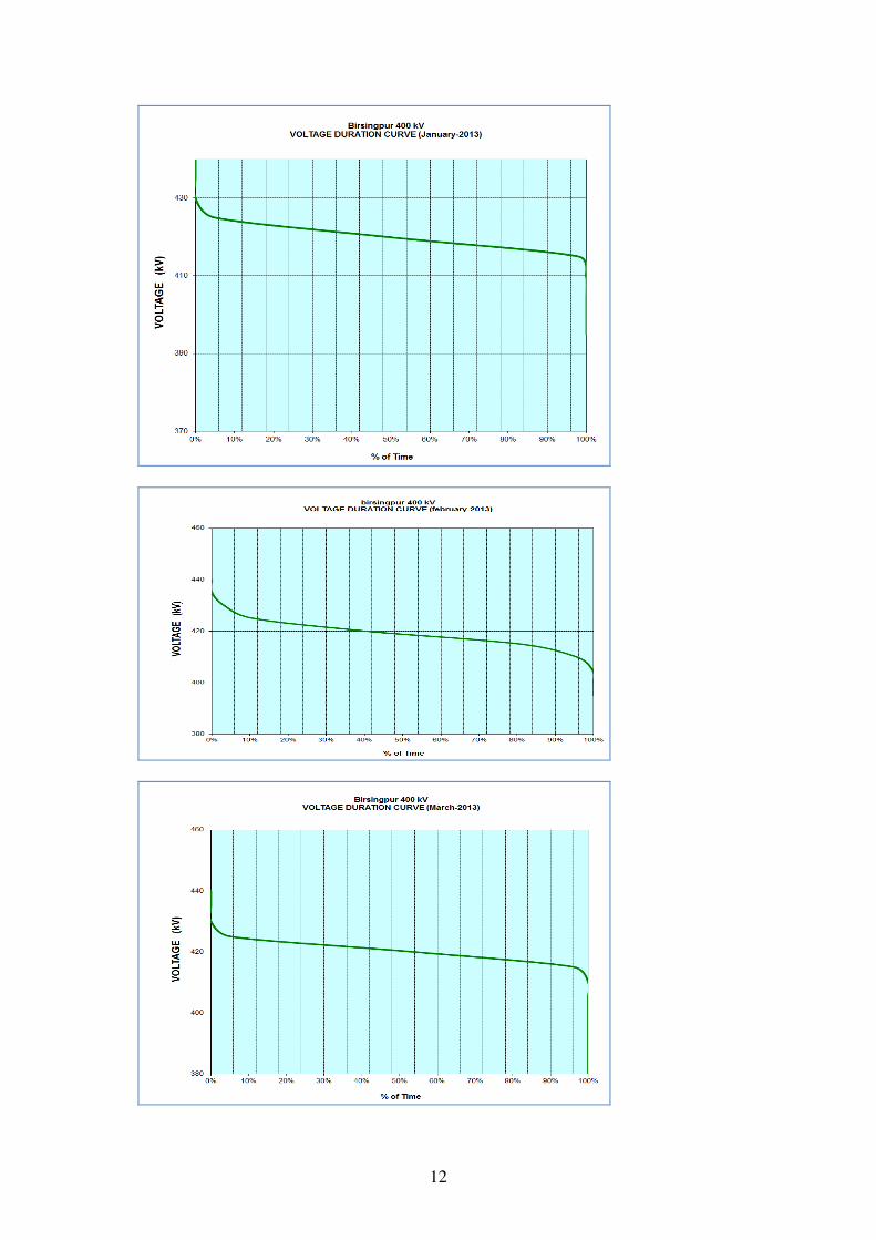
2.1 MPPTCL vide their letter dated 18.06.2013 has intimated that voltage at 400 kV substation of Birsinghpur TPS remains high above 425 kV most of the time. The outage of 500 MW unit at Birsinghpur TPS results in voltage above 430 kV. To control the voltage at Birsinghppur 400 kV substation the Birsinghpur – Katni 400 kV D/C line and Birsinghpur – Damoh 400 kV S/C line is required to be kept out of service. Even one circuit of Birsinghpur – Damoh 400 kV D/C line also has to be kept out of service on various occasions to control overvoltage, consequently endangering grid security.
2.2 To control overvoltage at Birsinghpur, MPPTCL has proposed installation of one 125 MVAR bus reactor at Birsinghpur TPS switchyard by MPPGCL.
2.3 The overvoltage issue at Birsinghpur has also been reported by NLDC in their operational feedback. The voltage duration curve for January 2013 to March 2013 taken from NLDC report is shown below:
12

13
2.4 The results of the study furnished by MPPTCL is given below:
2.5 Members may concur the proposal of MPPTCL.
3.0 Evacuation of Power from Adani Mundra Generation Project
3.1 M/s Adani Power Limited (APL) has established a 4620MW generation project at
Mundra in Kutch dist. Gujarat. From their generation project, M/s Adani Power has tied up 3966 MW of power under long term, the details of which are as given below:
� Gujarat : 2000MW � Maharashtra : 200 MW � Haryana : 1424 MW � LTOA : 342 MW (With Punjab and Rajasthan (NR) as target
beneficiaries without Long Term PPA)
3.2 For transfer of power to Haryana, M/s Adani Power Limited has set up Mundra – Mohindergarh + 500kV HVDC 2500MW Bi-pole, Mohindergarh - Dhanonda 400kV (Quad) D/c and Mohindergarh – Bhiwani (PG) – 400kV D/c line as dedicated transmission system. Further M/s Adani Power Ltd applied for LTOA for 342 MW beyond Mohindergarh considering that 342 MW power is available at Mohindergarh HVDC terminal. LTOA for 342 MW was given beyond Bhiwani for which Mohindergarh – Bhiwani 400 kV D/c line was implemented by M/s Adani Power as dedicated line. Accordingly LTOA of 342 MW is still operational beyond Bhiwani.
3.3 After the commissioning of HVDC bipole, the issue of transfer of power through HVDC bipole was discussed at length among CEA, CTU and POSOCO. Keeping in view that Adani Mundra generation bus is connected to the HVDC terminal as well as to AC system and outage of a pole/bipole has impact on the power flow on AC

14
system as well as on inter-regional system, it was decided that power flow on Adani Mundra – Mohindergarh HVDC bipole line shall be maintained at 1500 MW considering the grid security in view.
3.4 While granting the Long Term Open Access for 342 MW to M/s Adani Power
Limited for Northern Region, it was indicated by M/s Adani Power that power would be available at Mohindergarh and accordingly system strengthening was finalized beyond Mohindergarh.
3.5 For transfer of power to Haryana, M/s Adani Power implemented 2500 MW HVDC bipole line as dedicated line. Since CEA’s Planning Criteria envisaged N-1 criteria, the transmission scheme developed by Adani Power need to take into account one pole outage. Accordingly with this criterion only 1250 MW power can flow under N-1 condition. Keeping this aspect in view it was stated during the 10th TCC & 11th NRPC meetings held on 05/01/2009 & 06/01/2009 that in the event of outage of HVDC pole M/s Adani Power would require to have run back system from their project to maintain loading on other lines within safe limit. In addition DISCOMs of Haryana would need to plan and implement load shedding scheme in the event of outage of pole/bipole.
3.6 The 342 MW, Long Term Access is in operation beyond Bhiwani according to the LTOA intimation and application. But for bringing power to Mohindergarh, security criteria (CEA’s Planning Criteria) need to be considered. This means that under one pole outage / under normal conditions for power transfer upto Mohindergarh, parallel AC system in WR, NR and inter-regional system between NR & WR shall be utilized for transfer of power. Now, M/s Adani Power has applied for Long Term Access at their generation switchyard, so that the adequacy of parallel AC system is ascertained and suitable strengthening is planned for transferring power to NR. As per the LTA application, point for LTA is Adani Generation bus. At present Adani generation bus is not an ISTS bus, accordingly LTA is being processed considering usage of ISTS system beyond dedicated system of Adani / STU system and LTA is proposed to be granted for usage of ISTS system of Western Region, Northern Region and Inter-regional system. While processing the LTA application system adequacy of dedicated system as well of STU system in the vicinity has been analysed.
3.7 The system studies have been carried out considering two different scenarios ( enclosed as Annexure-II)
• Scenario 1 : Present Scenario
• Scenario 2 : Scenario after commissioning of Adani Mundra – Zerda 400 kV D/c line.
In all the above studies full dispatch has been considered from Adani generation including 342 MW dispatch to Northern Region. The details of the studies are discussed below: Scenario 1

15
This study is for present scenario. The base case load flow study results are enclosed at Exhibit-VII. From the base case it may be observed that the loading on Mundra – Sami is 595 MW per ckt, Gwalior – Agra is 981 per ckt etc. In general loading is within limits in base case. Thereafter different contingencies have been studied: a) Contingency of outage of one ckt of Gwalior – Agra 765 kV S/c line
(Enclosed at Exhibit-VII-01) b) Contingency of outage of one ckt of Mundra – Sami 400 kV S/c line
(Enclosed at Exhibit-VII-02) From the above study results it may be seen that under the outage of one ckt of Mundra – Sami 400 kV S/c line, the remaining line gets loaded to 919 MW, which is critical. From the above it may be seen that full power from Adani Mundra generation including 342 MW of LTA to NR cannot be evacuated.
Scenario 2: This study has been carried out with 1500 MW power transfer through HVDC bipole and full generation. In this case additional 400 kV D/c line from Adani Mundra generation bus to Zerda has been considered. As per the preliminary information gathered from GETCO (same to be confirmed from GETCO), Adani Mundra generation bus to Zerda 400 kV D/c line would be commissioned during last quarter of 2013-14. The base case load flow study results are enclosed at Exhibit-VIII. From the base case it may be observed that the loading on Mundra – Sami is 400 MW per ckt and Gwalior – Agra is 965 per ckt. In general loading is within limits in base case. Subsequently following contingencies have been studied:
a) Contingency of outage of one ckt of Gwalior – Agra 765 kV S/c line (Enclosed at Exhibit-VIII-01)
b) Contingency of outage of one ckt of Mundra – Sami 400 kV S/c line (Enclosed at Exhibit-VIII-02)
c) Contingency of outage of one pole and outage of one ckt of Mundra – Sami 400 kV S/c line (Enclosed at Exhibit-VIII-03)
From the above study results, no problem is envisaged in transfer of 342 MW to Northern region and the system can meet the security criteria as prescribed in Manual on Transmission Planning Criteria of January 2013. As per the studies carried out, no problem is envisaged in meeting the N-1-1 criteria as detailed in Planning Criteria. Keeping above in view it is proposed that LTA of 342 MW to Northern region from Adani Mundra generation can become effective after the completion of Mundra – Zerda 400 kV D/c line. This LTA request may be treated as change in LTA from Bhiwani to Adani Mundra generation bus of already granted LTA of 342 MW subject

16
to that all other terms and conditions remaining the same. Till that time the LTOA for 342 MW shall remain applicable beyond Mohindergarh / Bhiwani.
3.8 In long term perspective, an additional line from Adani Mundra generation bus to Banaskanta / Bhuj pooling station needs to be considered and integrated with the high capacity corridor being planned with RE generation projects in Rajasthan and Gujarat.
3.9 Members may deliberate.
4.0 Response to POSOCO report on Operational Feedback on Transmission Constraints
4.1 POSOCO in its report on ‘Operational Feedback on Transmission Constraints - April 2013’ has listed transmission lines and ICTs which are experiencing constraints due to overloading and also the nodes experiencing high voltage. The report is available on POSOCO website (posoco.in >document>operational-feedback).
4.2 The constraints mentioned in the report are: Transmission lines constraints on Kawas-Ichapore 220 kV line, Sugen – Vapi 400 kV S/C line, Parli – Lonikhand 400 kV D/C line and the 400 kV D/C lines emanating from Mundra UMPP. ICT constraint on 3X315, 400/220 kV ICT at Vapi. Nodes experiencing high voltages Raipur, Raigarh, Birsinghpur, Khandwa, Damoh, Bhopal, Nagda, Rajgarh, Bhadrawati, Wardha, Dhule, Kolhapur, Bhusawal, Akola, Solapur, Mapusa, Bhilai, Lonikhand, Parli. Installation of 27 nos. of bus reactors at various locations in WR has been agreed in the 33rd and 34th SCM of WR and are under various stages of implementation. In DNH, Kala 400/220 kV substation has already been planned which would relieve the loading of Vapi ICTs. For Kawas- Ichapore overloading, the LILO of one circuit of Kawas- Vav at Ichapore may be implemented as decided in the 34th SCM of WR. To avoid overloading of Sugen-Vapi 400 kV S/C line, addition interconnection with Vapi has already been planned. Regarding Mundra UMPP, additional strengthening has been proposed in the agenda.
4.3 POSOCO may present the critical lines /corridors which require:
(i) the planned system to be implemented on priority
(ii) additional system to be planned.
4.4 Members may discuss.
5.0 Additional evacuation line from Vindhyachal-IV & V STPP (3x500 MW)

17
5.1 The immediate evacuation of Vindhyachal-IV & V STPP (VSTPP) consists of Vindhyachal-IV generation switchyard-Vindhyachal Pool 400 kV D/c (quad) line. NTPC vide their letter no. CC:PEE:2260:270/2 dated 10.07.2013 have requested to provide additional outlet from Vindhyachal-IV generation switchyard in order to increase the reliability of the power evacuation system for VSTPP-IV & V project
5.2 In view of the above and to meet the “n-1-1” contingency, following additional transmission system for Vindhyachal-IV & V is proposed:
(i) Vindhyachal-IV & V STPP – Vindhyachal Pool 400 kV D/c (quad) line.
5.3 Members may deliberate and approve.
6.0 Termination of Vapi – Navi Mumbai 400kV D/c line at upcoming Kudus substation of MSETCL.
6.1 In the meeting of 35th Standing Committee meeting on Power System Planning for
Western Region held on 3rd January, 2013 at Gurgaon, it was agreed to terminate
Vapi – Navi Mumbai 400 kV D/c line at upcoming Kudus substation of MSETCL in
view of severe RoW problem. It was desired that POWERGRID will continue their
effort for completing the balance portion of Vapi-Navi Mumbai 400 kV D/c line.
6.2 MSETCL have informed POWERGRID in May, 2013 that all bays available at
Kudus are earmarked for the lines already sanctioned. Therefore to provide bays
for termination, MSETCL has proposed that LILO of only one circuit of Tarapur –
Padghe 400 kV D/c may be done at Kudus thereby releasing two nos. of 400 kV
bays at Kudus and utilizing these bays for terminating Vapi –Navi Mumbai 400 kV
D/c line at Kudus. LILO of Tarapur – Phadge 400 kV D/C line at Kudus (MSETCL)
400 kV substation was proposed by MSETCL in the 32nd SCM and the same was
agreed by the members with a request to MSETCL to plan outlets beyond kudus
towards load centres.
6.3 POWERGRID has informed due to severe Right-of-Way constraint in the portion
between Kudus & Navi Mumbai, the line portion between Kudus and Navi Mumbai
cannot be constructed. Hence, it is proposed to modify Vapi-Navi Mumbai 400kV
D/c line under WRSS-V as Vapi-Kudus 400kV D/c line.
6.4 Members may deliberate.

18
7.0 Commissioning of 2x25% FSC of Rajgarh – Karamsad (Kasor) 400 kV D/c line.
7.1 Western Region Transmission Gujarat Private Limited (WRTGPL), a subsidiary of
Reliance Power Transmission Limited is implementing Rajgarh – Kasor 400 kV D/c
line which is held up due to forest clearances. POWERGRID was to implement the
bay extensions and 2x25% FSC for above line. POWERGRID has already
implemented both the bays as well as FSC. FSC is available since September,
2011 but could not be commissioned due to non-availability of Rajgarh – Kasor 400
kV D/c line.
7.2 Rajgarh – Kasor 400 kV D/c line is not likely to be commissioned in near future and
since the commissioning of 2x25% FSC is pending since September, 2011 and
involves contractual issues, it has been proposed by POWERGRID that the FSC
may be tested and commissioned by connecting to some other 400 kV line
emanating from Rajgarh 400 kV substation as an interim arrangement. The
modalities of the interim arrangement would be presented by POWERGRID in the
meeting.
7.3 Members may deliberate.
8.0 Additional evacuation line from Sasan UMPP (6x660 MW)
8.1 POSOCO has recently reported multiple outages in the system and suggested
reliable evacuation system in planning horizon from major generation complexes.
The evacuation of major generation complex Sasan (6x660 MW) has been
reviewed in this regard. The immediate evacuation of Sasan UMPP consists of
following elements:
(i) Sasan UMPP – Satna 765 kV 2xS/c line
(ii) Sasan UMPP – Vindhyachal Pool 765 kV S/c line
(iii) 2x1000 MVA, 765/400 kV at Sasan UMPP
Looking at the multiple contingency from Sasan complex, constraints shall be faced
with outage of Sasan – Satna 765 kV 2xS/c lines and accordingly it is proposed to
provide one more outlet from Sasan as Sasan – Vindhyachal Pool 765 kV S/c line.
Load Flow studies in this regard are enclosed (Annexure-III).
Exhibit-III : Base Case with existing system
Exhibit-IIIA : Base case with Sasan – Satna 765 kV 2XS/c line outage

19
Exhibit-IV : Base Case with system strengthening
Exhibit-IVA : Base case with Sasan – Satna 765 kV 2XS/c line outage
8.2 Members may deliberate.
9.0 Augmentation of Transformation capacity at Damoh Station.
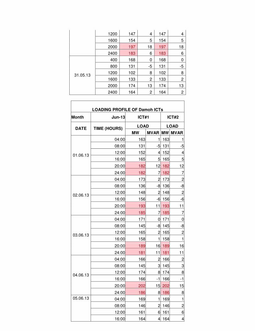
9.1 POWERGRID has intimated that loading pattern of 400/220 kV ICTs at Damoh
sub-station of POWERGRID during last one year has revealed that loading on all
the ICTs operating at this Substation had exceeded 250 MW on several occasions
and maximum loading on each ICT at the sub-station had gone up to 282 MW
during April, 2013. The ICTs loadings for different months are enclosed at
Annexure-IV.
9.2 In view of above such increased loading pattern and to meet any eventuality due to
failure of anyone of the ICTs at the above sub-station, it is proposed for
augmentation of transformation capacity by installing additional 1x500 MVA ICT as
tripping of any one of the ICTs may lead to overloading of other ICT and might
cause cascaded tripping of remaining ICT in service leading to complete outage.
10.0 Members may deliberate.
11.0 Reactive Power Management in Western Regional grid
11.1 During the light load conditions in Western Region, it has been observed that
voltages are in the range of 430-435 kV which is at critical limits. POSOCO as
operational feedback is also regularly reporting high voltages at many locations in
WR. In the recent report of POSOCO Operational Feedback on Transmission
Constraints (April, 2013) POSOCO have reported the following nodes experiencing
high voltages.
“Raipur, Raigarh, Birsinghpur, Khandwa, Damoh, Bhopal, Nagda, Rajgarh,
Bhadrawati, Wardha, Dhule, Kolhapur, Bhusawal, Akola, Solapur, Mapusa, Bhilai,
Lonikhand & Parli.”
11.2 During the meeting of 33rd & 34th Standing Committee meeting on Power System
Planning for Western Region, the issue of overvoltage and requirement of reactive
compensation in the grid was deliberated. With the market development, the
variation of power flow on transmission corridor is increasing. Thus, for reactive
power management in the grid under such unpredictable scenario, it is necessary
to provide adequate reactive compensation all over the grid.

20
Keeping above in view, the following POWERGRID has proposed:
a) 1x125 MVAR, 420 kV Bus Reactor at all the 400 kV substations of WR wherein
presently no bus reactors are existing/planned by respective utility
b) 1x330MVAR, 765 kV at all the 765 kV substations of WR wherein presently no
bus reactors are existing/planned by respective utility
c) 1x125 MVAR, 420 Bus Reactor in the generation switchyard of all generators by
respective utility wherever no bus reactor exists to control the over-voltages in
the system.
d) Converting all line reactors at sending end into switchable line reactors
(depending on space available)
11.3 Members may deliberate.
12.0 Additional System Strengthening Scheme for Chhattisgarh IPPs
12.1 POWERGRID is implementing a composite high capacity corridor planned for
Chattisgarh IPPs having 18,000 MW installed capacity. Considering the uncertainty
of materialization of these IPPs at the time of planning, the high capacity corridor
was planned with minimum redundancy. The immediate evacuation lines form
Chattisgarh complex inter-alia consists of following lines:
(i) Champa (Pool) – Kurukshetra + 800 kV, 6000 MW HVDC bi-pole
(ii) Raigarh (Kotra) – Pugalur + 600 kV, 4000 MW HVDC bi-pole
(iii) Raipur (Pool) – Wardha Pool 765 kV 2xD/c line
(iv) Champa (Pool) – Dharamjaigarh 765 kV S/c line
12.2 POWERGRID has informed that in the Chattisgarh complex progress of about
21,000 MW generation (List enclosed at Annexure-V) is encouraging and many of
these are already commissioned. Further, few projects have also taken connectivity
over this corridor. To provide reliable evacuation of power from this complex, the
following transmission system strengthening for Chhattisgarh IPPs is proposed:
(i) Raipur (Pool) – Rajnandgaon 765 kV D/c line
(ii) Rajnandgaon – Warora (Pool) 765 kV D/c line
(iii) LILO of one circuit of Aurangabad – Padghe 765 kV D/c line at Pune (in
lieu of LILO of one circuit of Kolhapur – Padghe at Pune)

21
(iv) Establishment of new substation near Rajnandgaon 765/400 kV, 2x1500
MVA substation
(v) LILO of all circuits of Raipur/Bhilai – Bhadrawati 400 kV lines at
Rajnandgaon
(vi) Raigarh (Kotra) - Champa (Pool) – Dharamjaigarh 765 kV 2nd S/c line.
Load Flow Studies are enclosed (Annexure – V)
Exhibit-I : Base Case without system strengthening
Exhibit-IA : Base Case without system strengthening and with outage Raipur –
Wardha 765 kV D/c line
Exhibit-IB : Base Case without system strengthening and Raigarh – Pugalur
HVDC bipole outage
Exhibit-II : Base Case with system strengthening
Exhibit-IIA : Base Case with system strengthening and with outage Raipur –
Wardha 765 kV D/c line
Exhibit-IIB : Base Case with system strengthening and Raigarh – Pugalur HVDC
bipole outage
From the results, it may be observed that the loadings of all 400/765 kV lines are
within their limits with system strengthening.
12.3 Members may deliberate and approve.
13.0 Transmission system for increasing import of power into Southern Region
13.1 In the meeting of 31st Standing Committee meeting on Power System Planning for Western Region held on 27th December 2010 at Gurgaon, it was agreed to implement Wardha – Hyderabad 765 D/c line (inter-regional line between WR & SR).
13.2 Subsequently in the meeting of 35th Standing Committee meeting on Power System
Planning for Southern Region held on 4th January 2013 at Gurgaon, it was decided
by SR constituents to anchor planned Hyderabad –Wardha 765kV D/C line at some
intermediate station as the length of this line was becoming more than 500 km as
per the preliminary survey. The increase in line length is due to line routing, to
avoid Hyderabad City limits and Forest stretches. After discussions, it was decided
in above meeting of SR that the location and connectivity at 400kV level of the
intermediate station would be decided on the basis of joint studies/visit by CTU,
APTRANSCO and CEA. During the joint studies of a team comprising of officers

22
from CTU, CEA and APTRANSCO it was found that Nizamabad could be the
perspective location for the intermediate station. POWERGRID and APTRANSCO
has identified 3-4 locations around Nizamabad area, and the proposed line lengths
of the Wardha – Nizamabad and the Nizamabad - Hyderabad would be
approximately 250km.
13.3 Following connectivity for Nizamabad was studied and finalized in joint studies with
PGCIL, APTRANSCO, TNEB and KPTCL held in Hyderabad on 28-30 June 2013:
i. Establishment of Nizamabad 765/400kV substation with 2x1500 MVA
transformers
ii. Nizamabad – Dichpalli 400kV D/c line
iii. Nizamabad – Yeddumailaram (Shankarapalli) 400kV D/c line
iv. LILO of Nizamabad – Yeddumailaram (Shankarpalli) 400kV D/c line at Narsapur
– by APTRANSCO
13.4 In view of the above, Wardha – Hyderabad 765 kV D/c line agreed earlier shall now
be Wardha – Nizamabad – Hyderabad 765 kV D/c.
13.5 Members may note.
14.0 Transmission system associated with New IPP projects in Chattishgarh-Shifting of converter terminal associated with + 600 kV 4000 MW, Raigarh (Kotra) – Dhule HVDC line from Dhule in Western Region to a suitable location in Southern Region.
14.1 In the meeting of 35th Standing Committee meeting on Power System Planning for
Western Region held on 3rd January 2013 at Gurgaon, it was agreed to terminate
the HVDC terminal of Raigarh (Kotra) – Dhule HVDC bi-pole in Southern Region
(near Chennai) instead of Dhule.
14.2 Accordingly, CEA, SR constituents & POWERGRID have carried out the joint
studies and proposed the following transmission scheme:
(i) Raigarh (Kotra) – Pugalur + 600 kV, 4000 MW HVDC bipole
(ii) Pugalur HVDC Station – Pugalur Existing 400kV (quad) D/c line
(iii) Pugalur HVDC Station – Arasur 400kV (quad) D/c line
(iv) Pugalur HVDC Station – Thiruvalam 400kV (quad) D/c line
(v) Pugalur HVDC Station – Edayarpalayam – Udumalpet 400kV (quad) D/c line
(vi) Establishment of 400/220kV substation with 2x500 MVA transformers at
Edayarpalayam

23
14.3 Members may kindly note.
15.0 Development of Analytics as part of Unified Real Time Dynamic State
Measurement (URTDSM) scheme
15.1 Implementation of Unified Real Time Dynamic State Measurement (URTDSM) scheme as system strengthening was agreed in the Joint meeting of all the five (5) Regional Standing committees on Power System Planning held on 05.03.2012. It consists of installation of Phasor Measurement Unit(PMU) at existing State, ISTS and IPP stations and lines at 400kV and above including that coming up by 2014-15, generation switchyard at 220kV and above, Phasor Data Concentrator(PDC) at all SLDC, RLDC & NLDC along with OPGW communication links.
15.2 In URTDSM, the user interface application software is proposed to visualize and analyze the real time phasor data. It was also decided that following analytics are to be developed in parallel with implementation of the URTDSM scheme in association with premier academic institutions like IIT using PMU based measurement.
• Vulnerability analysis of distance relays • Linear state estimator • Supervised Zone-3 distance protection scheme to prevent unwanted
tripping of backup distance relays • CT/CVT calibration • Line Parameter Estimation • Control Schemes for improving system security (based on angular,
voltage and frequency instability) Based on the discussion, development of above analytics in association with IIT Bombay progressively in three(3) years has been undertaken which will be installed at all SLDC, RLDC, NLDC, RPC, CEA and CTU.
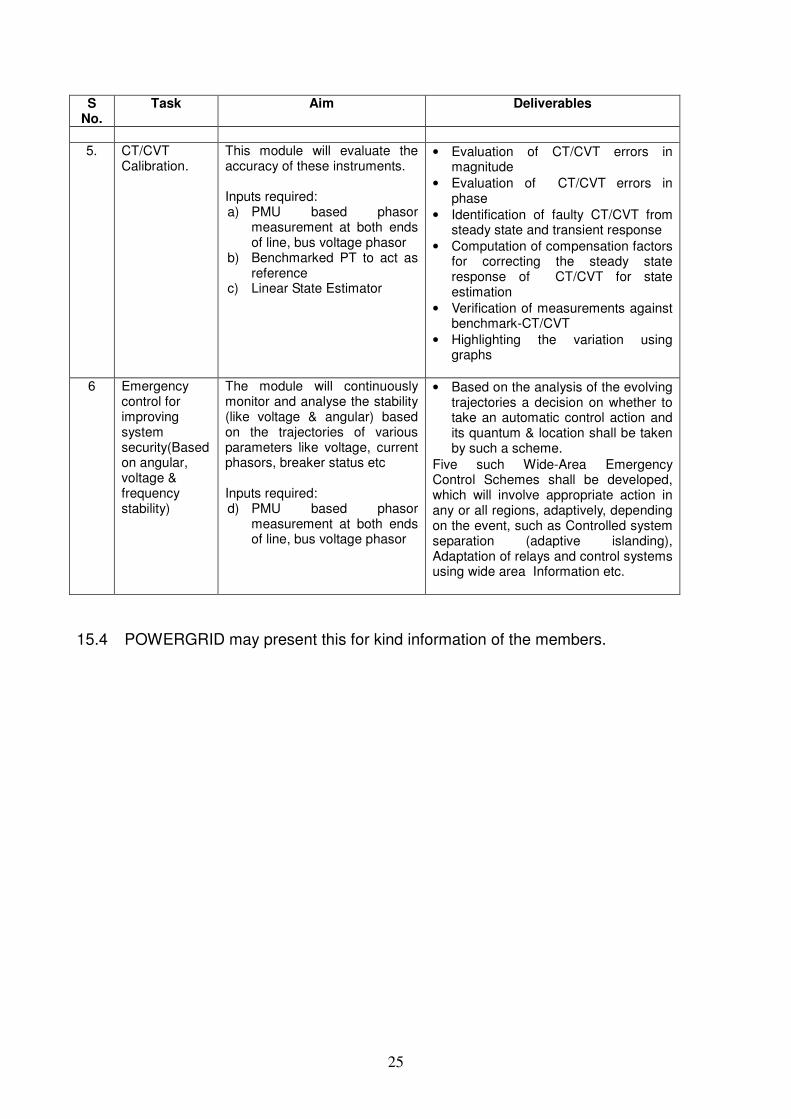
15.3 Purpose and deliverables for above analytics is given below. DEVELOPMENT OF ANALYTICAL TOOLS USING PMU BASED PHASOR MEASUREMENTS
S
No. Task Aim Deliverables
1. Line Parameter Estimation
Estimate & Validate transmission line parameter. Inputs required: a) PMU based phasor
measurement at both ends of line, bus voltage phasor
• Positive and Zero sequence Line parameter estimation (R,X,B)
• Errors in line parameters will be logged for information to operator & correction in linear state estimator parameter.
2. On line vulnerability analysis of distance
Development of software for validating distance relay characteristic (Zone-1, Zone-2, Zone-3) in real time basis by
• Visualization of relay characteristic and apparent impedance trajectory in the R-X plane.
• Alarm / messages when thresholds

24
S No.
Task Aim Deliverables
relays.
superimposing on field setting of distance relays. Inputs required: b) PMU based phasor
measurement at both ends of line, bus voltage phasor
c) Distances relay characteristic and settings.
are violated or apparent impedance is some margin (say 20%) from Zone 1, 2 or Zone 3 characteristics of the relay.
• Identification of power swing beyond a configurable threshold due to any disturbance in the system
• Identification of load encroachment condition in the system
• Creation & storage of distance relay characteristics of different lines using templates & available settings
• Data available in standard format(CSV, excel, comtrade)
• Trigger input for DSA
3. Linear State Estimator
Development of 3-phase linear state estimator, software based on weighted least square technique. Inputs required: a) PMU based phasor
measurement at both ends of line and bus voltage phasor,
b) Substation bus switching scheme/topology
• Network topology processor to update the bus model
• Bad data detection
• Topology error detection to identify the switch device errors
• Observability analysis to identify maximum observable network with available measurement.
• Pseudo & historical measurement generation in case of lack of observability.
• Alarms & warnings for model inconsistencies & limit violation.
• Network connectivity/graph to provide:
• Island details
• Issue alarm for loss of connectivity
• visualisation by making line dotted/different colour
• Component outage
• Visualization of state estimator output in tabular & graphical form.
• Power system condition can be played-back along with topology connectivity and flow measurement
• Three phase State Estimator
4. Supervised Zone-3 distance protection scheme to prevent unwanted tripping
The analytics will provide adaptive Zone-3 backup protection to avoid unwanted Zone-3 tripping. Inputs required: a) PMU based phasor
measurement at both ends of line and bus voltage
b) Distance relay characteristics and settings of candidate line
• Identification of presence of persistent fault in the observable system.
• Identification of presence of power swing & load encroachment in the observable system.
• The software will generate control signal for disabling of Zone -3 protection based on system condition and adopted protection philosophy
25
S No.
Task Aim Deliverables
5. CT/CVT Calibration.
This module will evaluate the accuracy of these instruments. Inputs required: a) PMU based phasor
measurement at both ends of line, bus voltage phasor
b) Benchmarked PT to act as reference
c) Linear State Estimator
• Evaluation of CT/CVT errors in magnitude
• Evaluation of CT/CVT errors in phase
• Identification of faulty CT/CVT from steady state and transient response
• Computation of compensation factors for correcting the steady state response of CT/CVT for state estimation
• Verification of measurements against benchmark-CT/CVT
• Highlighting the variation using graphs
6 Emergency control for improving system security(Based on angular, voltage & frequency stability)
The module will continuously monitor and analyse the stability (like voltage & angular) based on the trajectories of various parameters like voltage, current phasors, breaker status etc Inputs required: d) PMU based phasor
measurement at both ends of line, bus voltage phasor
• Based on the analysis of the evolving trajectories a decision on whether to take an automatic control action and its quantum & location shall be taken by such a scheme.
Five such Wide-Area Emergency Control Schemes shall be developed, which will involve appropriate action in any or all regions, adaptively, depending on the event, such as Controlled system separation (adaptive islanding), Adaptation of relays and control systems using wide area Information etc.
15.4 POWERGRID may present this for kind information of the members.

26
ANNEXURE – I


27
ANNEXURE - II

BASECASE
EXHIBIT-VII

EXHIBIT=VII-01
Outage of one ckt of Gwalior – Agra 765 kV S/c

Outage of one circuit of Adani-Sami 400 kV
EXHIBIT-VII-02

EXHIBIT-VIII
BASECASE

EXHIBIT-VIII-01
outage of one ckt of Gwalior – Agra 765 kV S/c

EXHIBIT VIII-02
outage of one ckt of Mundra – Sami 400 kV S/c

EXHIBIT-VIII-03
outage of one pole and outage of one ckt of Mundra – Sami 400 kV S/c

28
ANNEXURE -III

EXHIBIT-III

EXHIBIT-IIIA

EXHIBIT-IV

EXHIBIT-IVA

29
ANNEXURE -IV

Annexure – IV
LOADING PROFILE OF Damoh ICTs
Month Apr-13 ICT#1 ICT#2
LOAD LOAD DATE
TIME (HOURS) MW MVAR MW MVAR
01.04.13 400 158 1 158 1
800 128 4 128 4
1200 112 9 112 9
1600 97 7 97 7
2000 183 22 183 22
2400 161 11 161 11
06.04.13 400 153 7 153 7
800 130 4 130 4
1200 174 7 0 0
1600 86 -3 86 -3
2000 197 34 197 34
2400 172 16 172 16
07.04.13 400 161 4 161 4
800 135 3 135 3
1200 89 10 89 10
1600 93 3 93 3
2000 193 32 193 32
2400 162 10 162 10
08.04.13 400 155 4 155 4
800 136 0 136 0
1200 114 3 114 3
1600 104 -2 104 -2
2000 183 22 183 22
2400 268 13 268 13
10.04.13 400 169 7 169 7
800 129 2 129 2
1200 122 1 122 1
1600 128 0 128 0
2000 193 23 193 23
2400 181 9 181 9
11.04.13 400 176 6 176 6
800 134 0 134 0
1200 136 3 136 3
1600 127 -2 127 -2
2000 193 20 193 20
2400 179 8 179 8
20.04.13 400 158 11 158 11

800 126 -1 126 -1
1200 99 2 99 2
1600 95 -1 95 -1
2000 184 13 184 13
2400 182 1 182 1
21.04.13 400 189 -2 189 -2
800 147 0 147 0
1200 90 0 90 0
1600 156 17 156 17
2000 175 11 175 11
2400 138 14 138 14
22.04.13 400 140 3 140 3
800 107 -2 107 -2
1200 184 15 184 15
1600 80 8 80 8
2000 282 44 282 44
2400 197 31 197 31
23.04.13 400 194 20 194 20
800 125 7 125 7
1200 149 17 149 17
1600 124 2 124 2
2000 219 41 219 41
2400 209 23 209 23
24.04.13 400 206 15 206 15
800 131 3 131 3
1200 142 29 142 29
1600 101 13 101 13
2000 229 49 229 49
2400 220 23 220 23
26.04.13 400 211 23 211 23
800 140 6 140 6
1200 139 27 139 27
1600 131 10 131 10
2000 232 57 232 57
2400 229 42 229 42
27.04.13 400 142 21 142 21
800 139 11 139 11
1200 118 17 118 17
1600 110 18 110 18
2000 241 54 241 54
2400 235 23 235 23
28.04.13 400 145 11 145 11
800 145 9 145 9

1200 146 23 146 23
1600 156 24 156 24
2000 211 43 211 43
2400 216 41 216 41
29.04.13 400 216 41 216 41
800 148 3 148 3
1200 145 28 145 28
1600 139 13 139 13
2000 239 51 239 51
2400 231 27 231 27
30.04.13 400 225 31 225 31
800 148 3 148 3
1200 109 21 109 21
1600 141 29 141 29
2000 199 57 199 57
2400 195 46 195 46
LOADING PROFILE OF Damoh ICTs
Month May-13 ICT#1 ICT#2
LOAD LOAD DATE
TIME (HOURS) MW MVAR MW MVAR
400 222 29 222 29
800 157 -2 157 -2
1200 162 24 162 24
1600 130 5 130 5
2000 239 38 239 38
01.05.13
2400 227 24 227 24
400 206 30 206 30
800 160 -2 160 -2
1200 146 16 146 16
1600 151 5 151 5
2000 243 41 243 41
02.05.13
2400 222 25 222 25
400 229 30 229 30
800 152 10 152 10
1200 75 4 75 4
1600 112 5 112 5
2000 164 20 164 20
03.05.13
2400 170 15 170 15
400 177 7 177 7
800 149 3 149 3
1200 176 12 176 12
1600 174 14 174 14
04.05.13
2000 195 15 195 15

2400 179 12 179 12
400 185 15 185 15
800 144 3 144 3
1200 144 9 144 9
1600 135 6 135 6
2000 189 22 189 22
05.05.13
2400 180 13 180 13
400 163 15 163 15
800 136 4 136 4
1200 143 12 143 12
1600 136 22 136 22
2000 181 23 181 23
07.05.13
2400 182 10 182 10
400 173 6 173 6
800 149 4 149 4
1200 150 7 150 7
1600 130 0 130 0
2000 190 19 190 19
08.05.13
2400 177 7 177 7
400 186 2 186 2
800 149 -2 149 -2
1200 148 6 148 6
1600 145 0 145 0
2000 194 14 194 14
09.05.13
2400 179 8 179 8
400 171 3 171 3
800 144 -3 144 -3
1200 156 0 156 0
1600 145 -4 145 -4
2000 188 14 188 14
10.05.13
2400 180 15 180 15
400 153 5 153 5
800 129 -1 129 -1
1200 146 11 146 11
1600 153 5 153 5
2000 210 21 210 21
13.05.13
2400 178 8 178 8
400 182 6 182 6
800 146 14 146 14
1200 149 11 149 11
1600 155 9 155 9
175 175 11 175 11
14.05.13
2400 185 10 185 10
400 189 3 189 315.05.13
800 159 -2 159 -2

1200 148 3 148 3
1600 161 4 161 4
2000 180 12 180 12
2400 183 9 183 9
400 185 3 185 3
800 153 4 153 4
1200 149 4 149 4
1600 169 9 169 9
2000 176 8 176 8
16.05.13
2400 186 13 186 13
400 194 7 194 7
800 160 6 160 6
1200 150 5 150 5
1600 125 0 125 0
2000 187 27 187 27
17.05.13
2400 183 10 183 10
400 190 0 190 0
800 185 0 185 0
1200 145 3 145 3
1600 151 3 151 3
2000 251 15 251 15
18.05.13
2400 211 9 211 9
400 159 7 159 7
800 186 9 186 9
1200 188 -5 188 -5
1600 181 -8 181 -8
2000 229 11 229 11
19.05.13
2400 214 2 214 2
400 220 -4 220 -4
800 176 -13 176 -13
1200 167 5 167 5
1600 161 2 161 2
2000 193 22 193 22
20.05.13
2400 205 0 205 0
400 185 7 185 7
800 145 -5 145 -5
1200 162 5 162 5
1600 158 -7 158 -7
2000 170 9 170 9
21.05.13
2400 165 8 165 8
400 146 -6 146 -6
800 130 -7 130 -7
1200 144 2 144 2
1600 143 5 143 5
22.05.13
2000 181 21 181 21

2400 171 15 171 15
400 135 -5 135 -5
800 128 -10 128 -10
1200 162 3 162 3
1600 163 11 163 11
2000 190 23 190 23
23.05.13
2400 183 11 183 11
400 171 5 171 5
800 148 5 148 5
1200 146 0 146 0
1600 152 8 152 8
2000 161 4 161 4
24.05.13
2400 170 13 170 13
400 175 6 175 6
800 136 -5 136 -5
1200 147 7 147 7
1600 145 16 145 16
2000 197 27 197 27
25.05.13
2400 181 8 181 8
400 178 13 178 13
800 140 -1 140 -1
1200 150 9 150 9
1600 149 10 149 10
2000 189 21 189 21
26.05.13
2400 179 10 179 10
400 172 5 172 5
800 134 -8 134 -8
1200 149 10 149 10
1600 145 8 145 8
2000 197 26 197 26
27.05.13
2400 182 8 182 8
400 171 6 171 6
800 135 8 135 8
1200 147 5 147 5
1600 145 11 145 11
2000 200 20 200 20
28.05.13
2400 188 4 188 4
400 173 6 173 6
800 143 -3 143 -3
1200 165 8 165 8
1600 160 2 160 2
2000 200 17 200 17
29.05.13
2400 183 9 183 9
400 168 5 168 530.05.13
800 128 -2 128 -2
1200 147 4 147 4
1600 154 5 154 5
2000 197 18 197 18
2400 183 6 183 6
400 168 0 168 0
800 131 -5 131 -5
1200 102 8 102 8
1600 133 2 133 2
2000 174 13 174 13
31.05.13
2400 164 2 164 2
LOADING PROFILE OF Damoh ICTs
Month Jun-13 ICT#1 ICT#2
LOAD LOAD DATE TIME (HOURS)
MW MVAR MW MVAR
04:00 163 1 163 1
08:00 131 -5 131 -5
12:00 152 4 152 4
16:00 165 5 165 5
20:00 182 12 182 12
01.06.13
24:00 182 7 182 7
04:00 173 2 173 2
08:00 136 -8 136 -8
12:00 148 2 148 2
16:00 156 -6 156 -6
20:00 193 11 193 11
02.06.13
24:00 185 7 185 7
04:00 171 0 171 0
08:00 145 -8 145 -8
12:00 165 2 165 2
16:00 158 1 158 1
20:00 189 16 189 16
03.06.13
24:00 181 11 181 11
04:00 166 2 166 2
08:00 145 3 145 3
12:00 174 8 174 8
16:00 166 -1 166 -1
20:00 202 15 202 15
04.06.13
24:00 186 8 186 8
04:00 169 1 169 1
08:00 146 2 146 2
12:00 161 6 161 6
05.06.13
16:00 164 4 164 4

20:00 205 20 205 20
24:00 195 8 195 8
04:00 154 -6 154 -6
08:00 158 -7 158 -7
12:00 155 -9 155 -9
16:00 152 -11 152 -11
20:00 186 7 186 7
18.06.13
24:00 194 -2 194 -2
04:00 176 -6 176 -6
08:00 172 -10 172 -10
12:00 168 -6 168 -6
16:00 157 -5 157 -5
20:00 191 6 191 6
19.06.13
24:00 191 1 191 1
04:00 171 -5 171 -5
08:00 159 -6 159 -6
12:00 154 -3 154 -3
16:00 159 -3 159 -3
20:00 181 9 181 9
20.06.13
24:00 189 6 189 6
04:00 167 2 167 2
08:00 148 -6 148 -6
12:00 150 -4 150 -4
16:00 158 3 158 3
20:00 188 10 188 10
23.06.13
24:00 183 8 183 8
04:00 167 -3 167 -3
08:00 171 -1 171 -1
12:00 163 -3 163 -3
16:00 147 -2 147 -2
20:00 186 12 186 12
24.06.13
24:00 191 6 191 6
04:00 180 1 180 1
08:00 147 -3 147 -3
12:00 165 1 165 1
16:00 146 -5 146 -5
20:00 183 10 183 10
25.06.13
24:00 182 1 182 1

30
ANNEXURE - V

Annexure- V
Details of IPP Projects in Chhattisgarh
Applicant Installed Capacity (MW)
RAIGARH(KOTRA) COMPLEX
1 RKM Powergen Ltd.(4x360) 1440
2 Athena Chhattisgarh Power Ltd.(2x600) 1200
3 SKS Power Gen. (Ch) Ltd.(4x300) 1200
4 Korba West Power Co. Ltd.(1x600) 600
5 DB Power Ltd.(2x600) 1200
6 Visa Power Ltd. 1200
RAIGARH(TAMNAR) COMPLEX
1 Jindal Power Ltd.(4x600) 2400
2 Jindal Power Ltd. (225 MW from Dongamahua CPP+ 175MW from existing Tamnar TPS
400
3 TRN Energy Pvt. Ltd.(2x300) 600
4. Jayaswal Neco(600MW) 600
5. Sarda Energy Minerals(350MW) 350
JANJGIR-CHAMPA COMPLEX
1 KSK Mahanadi Power Co. Ltd (6x600) 3600
2 Lanco Amarkantak Power Pvt. Ltd.(2x660) 1320
3 NTPC Lara-I(2x800MW) 1600
RAIPUR COMPLEX
1 GMR Chhattisgarh Energy Pvt. Ltd. 1370
Dharamjaygarh/Kotra Complex
1 BALCO(4x300) 1200
2 Vandana Vidyut Ltd.(2x135+1x270) 540
Total 20,820 MW

BASE CASE W/O SYSTEM STRENGTHENING : BASE1
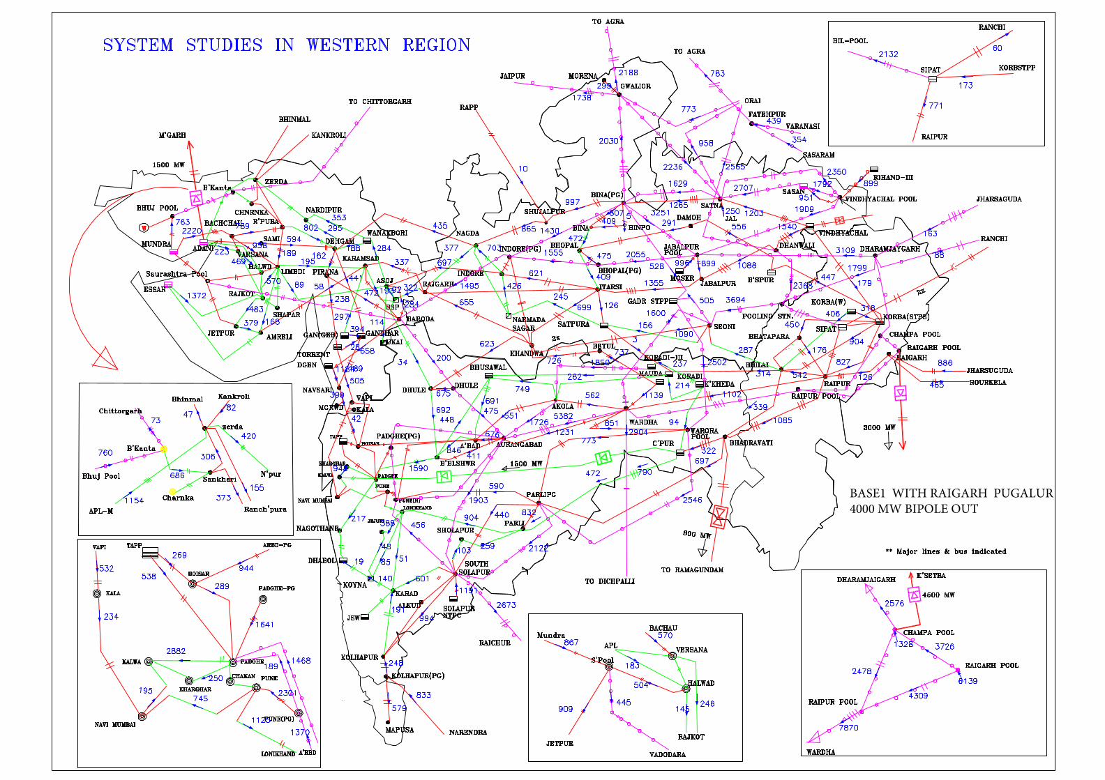
BASE1 WITH RAIGARH PUGALUR 4000 MW BIPOLE OUT

BASE1 WITH RAIPUR - WARDHA 765 Kv D/c LINE OUT

BASE CASE WITH SYSTEM STRENGHTHENING : BASE2

BASE2 WITH RAIGARH - PUGALUR4000 MW BIPOLE OUT

BASE2 WITH RAIPUR -WARDHA 765 KV D/C LINE OUT