supplemental service manual - aqua systems · supplemental service manual important: fill in...
TRANSCRIPT

SXT Timer
Supplemental Service Manual
IMPORTANT: Fill in Pertinent Information on Page 3 for Future Reference
Job Specification Sheet ......................................................................................................................................... 3
Timer Features ...................................................................................................................................................... 4
Timer Operation ..................................................................................................................................................... 6
Master Programming Mode Chart ......................................................................................................................... 8
Master Programming Mode ................................................................................................................................. 10
User Programming Mode .................................................................................................................................... 17
Diagnostic Programming Mode ........................................................................................................................... 18
2510 / 2750 / 2850s Timer Assembly .................................................................................................................. 20
9000 / 9100 / 9500 Twin Tank Timer Assembly ................................................................................................... 21
3/4” Plastic Turbine Meter Assembly ................................................................................................................... 22
3/4” Plastic Paddle Meter Assembly .................................................................................................................... 23
3/4” Brass Paddle Meter Assembly ..................................................................................................................... 24
1” Brass Paddle Meter Assembly ........................................................................................................................ 25
Inline Plastic Turbine Meter Assembly ................................................................................................................. 26
1 1/2” Brass Paddle Meter Assembly .................................................................................................................. 27
3/4”, 1” or 1 1/2” Paddle Wheel Meter Cap Assembly ......................................................................................... 28
2510SXT Wiring Diagram .................................................................................................................................... 29
2750SXT / 2850SXT Wiring Diagram .................................................................................................................. 30
9000SXT / 9100SXT / 9500SXT Wiring Diagram ................................................................................................ 31
Troubleshooting ................................................................................................................................................... 32
Service Assemblies ............................................................................................................................................. 33
Table of Contents
IMPORTANT PLEASE READ:
The information, specifications and illustrations in this manual are based on the latest information available at the time of •
printing. The manufacturer reserves the right to make changes at any time without notice.
This manual is intended as a guide for service of the valve only. System installation requires information from a number of •
suppliers not known at the time of manufacture. This product should be installed by a plumbing professional.
This unit is designed to be installed on potable water systems only.•
This product must be installed in compliance with all state and municipal plumbing and electrical codes. Permits may be •
required at the time of installation.
If daytime operating pressure exceeds 80 psi (5.5 bar), nighttime pressures may exceed pressure limits. A pressure reducing •
valve must be installed.
Do not install the unit where temperatures may drop below 32°F (0°C) or above 110°F (43°C). •
Do not place the unit in direct sunlight. Black units will absorb radiant heat increasing internal temperatures. •
Do not strike the valve or any of the components.•
Warranty of this product extends to manufacturing defects. Misapplication of this product may result in failure to properly •
condition water, or damage to product.
A prefilter should be used on installations in which free solids are present. •
In some applications local municipalities treat water with Chloramines. High Chloramine levels may damage valve components.•
Correct and constant voltage must be supplied to the control valve to maintain proper function.•

Job Number: __________________
Model Number: ________________
Water Hardness: ___________________ ppm or gpg
Capacity Per Unit: ______________
Mineral Tank Size: ___________ Diameter: ___________ Height:
Salt Setting per Regeneration: _____________________________________________
1. Type of Timer:
A. 7 Day or 12 Day B. Meter Initiated
2. Downflow: Upflow Upflow Variable
3. Meter Size:
A. 3/4” Std Range (125 - 2,100 gallon setting)
B. 3/4” Ext Range (625 - 10,625 gallon setting)
C. 1” Std Range (310 - 5,270 gallon setting)
D. 1” Ext Range (1,150 - 26,350 gallon setting)
E. 1-1/2” Std Range (625 - 10,625 gallon setting)
F. 1-1/2” Ext Range (3,125 - 53,125 gallon setting)
G. 2” Std Range (1,250 - 21,250 gallon setting)
H. 2” Ext Range (6,250 - 106,250 gallon setting)
I. 3” Std Range (3,750 - 63,750 gallon setting)
J. 3” Ext Range (18,750 - 318,750 gallon setting)
K. Electronic________ Pulse Count ________ Meter Size
4. System Type:
A. System #4: 1 Tank, 1 Meter, Immediate, or Delayed Regeneration
B. System #4: Time Clock
C. System #4: Twin Tank
D. System #5: 2-5 Tanks, 2 Meters, Interlock
E. System #6: 2-5 Tanks, 1 Meter, Series Regeneration
F. System #7: 2-5 Tanks, 1 Meter, Alternating
G. System #9: Electronic Only, 2-4 Tanks, Meter per Valve, Alternating
H. System #14: Electronic Only, 2-4 Tanks, Meter per Valve. Brings units on and offline based on flow.
5. Timer Program Settings:
A. Backwash: ______________________ Minutes
B. Brine and Slow Rinse: _____________ Minutes
C. Rapid Rinse: ____________________ Minutes
D. Brine Tank Refill: _________________ Minutes
E. Pause Time: ____________________ Minutes
F. Second Backwash: _______________ Minutes
6. Drain Line Flow Control: ____________ gpm
7. Brine Line Flow Controller: __________________ gpm
8. Injector Size#: _____________________
9. Piston Type:
A. Hard Water Bypass
B. No Hard Water Bypass
Job Specification Sheet
Page 4
Timer Features
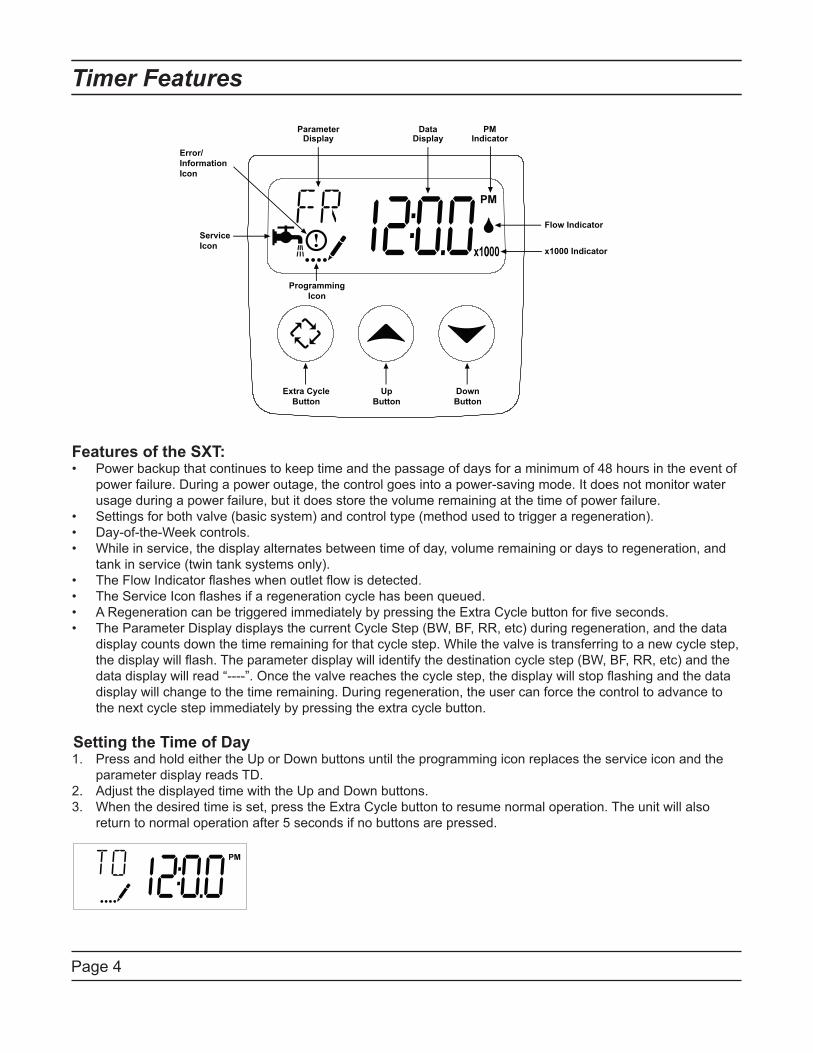
Features of the SXT:Power backup that continues to keep time and the passage of days for a minimum of 48 hours in the event of •
power failure. During a power outage, the control goes into a power-saving mode. It does not monitor water
usage during a power failure, but it does store the volume remaining at the time of power failure.
Settings for both valve (basic system) and control type (method used to trigger a regeneration).•
Day-of-the-Week controls.•
While in service, the display alternates between time of day, volume remaining or days to regeneration, and •
tank in service (twin tank systems only).
The Flow Indicator flashes when outlet flow is detected.•
The Service Icon flashes if a regeneration cycle has been queued.•
A Regeneration can be triggered immediately by pressing the Extra Cycle button for five seconds.•
The Parameter Display displays the current Cycle Step (BW, BF, RR, etc) during regeneration, and the data •
display counts down the time remaining for that cycle step. While the valve is transferring to a new cycle step,
the display will flash. The parameter display will identify the destination cycle step (BW, BF, RR, etc) and the
data display will read “----”. Once the valve reaches the cycle step, the display will stop flashing and the data
display will change to the time remaining. During regeneration, the user can force the control to advance to
the next cycle step immediately by pressing the extra cycle button.
Setting the Time of DayPress and hold either the Up or Down buttons until the programming icon replaces the service icon and the 1.
parameter display reads TD.
Adjust the displayed time with the Up and Down buttons.2.
When the desired time is set, press the Extra Cycle button to resume normal operation. The unit will also 3.
return to normal operation after 5 seconds if no buttons are pressed.
ParameterDisplay
DataDisplay
PMIndicator
Flow Indicator
x1000 Indicator
Service
Icon
Programming
Icon
Extra Cycle
Button
Up
Button
Down
Button
Error/
Information
Icon
Page 5
Timer Features
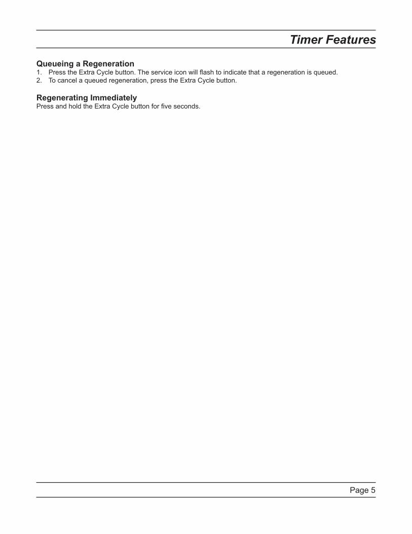
Queueing a RegenerationPress the Extra Cycle button. The service icon will flash to indicate that a regeneration is queued.1.
To cancel a queued regeneration, press the Extra Cycle button.2.
Regenerating ImmediatelyPress and hold the Extra Cycle button for five seconds.
Page 6
Timer Operation
Meter Immediate Control
A meter immediate control measures water usage and regenerates the system as soon as the calculated system
capacity is depleted. The control calculates the system capacity by dividing the unit capacity (typically expressed
in grains/unit volume) by the feedwater hardness and subtracting the reserve. Meter Immediate systems generally
do not use a reserve volume. However, in twin tank systems with soft-water regeneration, the reserve capacity
should be set to the volume of water used during regeneration to prevent hard water break-through. A Meter
Immediate control will also start a regeneration cycle at the programmed regeneration time if a number of days
equal to the regeneration day override pass before water usage depletes the calculated system capacity.
Meter Delayed Control
A Meter Delayed Control measures water usage and regenerates the system at the programmed regeneration
time after the calculated system capacity is depleted. As with Meter Immediate systems, the control calculates the
system capacity by dividing the unit capacity by the feedwater hardness and subtracting the reserve. The reserve
should be set to insure that the system delivers treated water between the time the system capacity is depleted
and the actual regeneration time. A Meter Delayed control will also start a regeneration cycle at the programmed
regeneration time if a number of days equal to the regeneration day override pass before water usage depletes
the calculated system capacity.
Time Clock Delayed Control
A Time Clock Delayed Control regenerates the system on a timed interval. The control will initiate a regeneration
cycle at the programmed regeneration time when the number of days since the last regeneration equals the
regeneration day override value.
Day of the Week Control
This control regenerates the system on a weekly schedule. The schedule is defined in Master Programming by
setting each day to either “off” or “on.” The control will initiates a regeneration cycle on days that have been set to
“on” at the specified regeneration time.
Control Operation During Regeneration
During regeneration, the control displays a special regeneration display. In this display, the control shows the
current regeneration step number the valve is advancing to, or has reached, and the time remaining in that step.
The step number that displays flashes until the valve completes driving to this regeneration step position. Once all
regeneration steps are complete the valve returns to service and resumes normal operation.
Pressing the Extra Cycle button during a regeneration cycle immediately advances the valve to the next cycle
step position and resumes normal step timing.
Control Operation During Programming
The control only enters the Program Mode with the valve in service. While in the Program Mode, the control
continues to operate normally monitoring water usage and keeping all displays up to date. Control programming is
stored in memory permanently, eliminating the need for battery backup power.
Manually Initiating a Regeneration
When timer is in service, press the Extra Cycle button for 5 seconds on the main screen.1.
The timer advances to Regeneration Cycle Step #1 (rapid rinse), and begins programmed time count down.2.
Press the Extra Cycle button once to advance valve to Regeneration Cycle Step #2 (backwash).3.
Press the Extra Cycle button once to advance valve to Regeneration Cycle Step #3 (brine draw & slow rinse).4.
Press the Extra Cycle button once to advance valve to Regeneration Cycle Step #4 (brine refill).5.
Press the Extra Cycle button once more to advance the valve back to in service. 6.
NOTE: If the unit is a filter or upflow, the cycle step order may change.
NOTE: A queued regeneration can be initiated by pressing the Extra Cycle button. To clear a queued
regeneration, press the Extra Cycle button again to cancel. If regeneration occurs for any reason prior to the
delayed regeneration time, the manual regeneration request shall be cleared.

Page 7
Timer Operation
Control Operation During A Power Failure
The SXT includes integral power backup. In the event of power failure, the control shifts into a power-saving
mode. The control stops monitoring water usage, and the display and motor shut down, but it continues to keep
track of the time and day for a minimum of 48 hours.
The system configuration settings are stored in a non-volatile memory and are stored indefinitely with or without
line power. The Time of Day flashes when there has been a power failure. Press any button to stop the Time of
Day from flashing.
If power fails while the unit is in regeneration, the control will save the current valve position before it shuts down.
When power is restored, the control will resume the regeneration cycle from the point where power failed. Note
that if power fails during a regeneration cycle, the valve will remain in it’s current position until power is restored.
The valve system should include all required safety components to prevent overflows resulting from a power
failure during regeneration.
The control will not start a new regeneration cycle without line power. If the valve misses a scheduled
regeneration due to a power failure, it will queue a regeneration. Once power is restored, the control will initiate
a regeneration cycle the next time that the Time of Day equals the programmed regeneration time. Typically,
this means that the valve will regenerate one day after it was originally scheduled. If the treated water output is
important and power interruptions are expected, the system should be setup with a sufficient reserve capacity to
compensate for regeneration delays.

Page 8
Master Programming Mode Chart
CAUTION: Before entering Master Programming, please contact your local professional water dealer.
Master Programming Options
Abbreviation Parameter Option
Abbreviation
Options
DF Display Format
GAL Gallons
Ltr Liters
Cu Cubic Meters
VT Valve Type
St1b Standard Downflow/Upflow Single Backwash
St2b Standard Downflow/Upflow Double Backwash
Fltr Filter
UFbF Upflow Brine First
8500 TwinFlo100SXT
Othr Other
CT Control Type
Fd Meter (Flow) Delayed
FI Meter (Flow) Immediate
tc Time Clock
dAY Day of Week
NT Number of Tanks1 Single Tank System
2 Two Tank System
TS Tank in Service
U1 Tank 1 in Service
U2 Tank 2 in Service
C Unit Capacity Unit Capacity (Grains)
HFeedwater
Hardness
Hardness of Inlet Water
RS Reserve Selection SF Percentage Safety Factor
rc Fixed Reserve Capacity
SF Safety FactorPercentage of the system capacity to be used as a
reserve
RCFixed Reserve
Capacity
Fixed volume to be used as a reserve
DO Day Override The system’s day override setting
RT Regen Time The time of day the system will regenerate
BW, BD, RR,
BF
Regen Cycle Step
Times
The time duration for each regeneration step.
Adjustable from OFF and 0-199 minutes.
NOTE: If “Othr” is chosen under “Valve Type”, then
R1, R2, R3, etc, will be displayed instead
D1, D2, D3, D4,
D5, D6, & D7
Day of Week
Settings
Regeneration setting (On or OFF) for each day of the
week on day-of-week systems
Page 9
Master Programming Mode Chart
CAUTION: Before entering Master Programming, please contact your local professional water dealer.
Master Programming Options
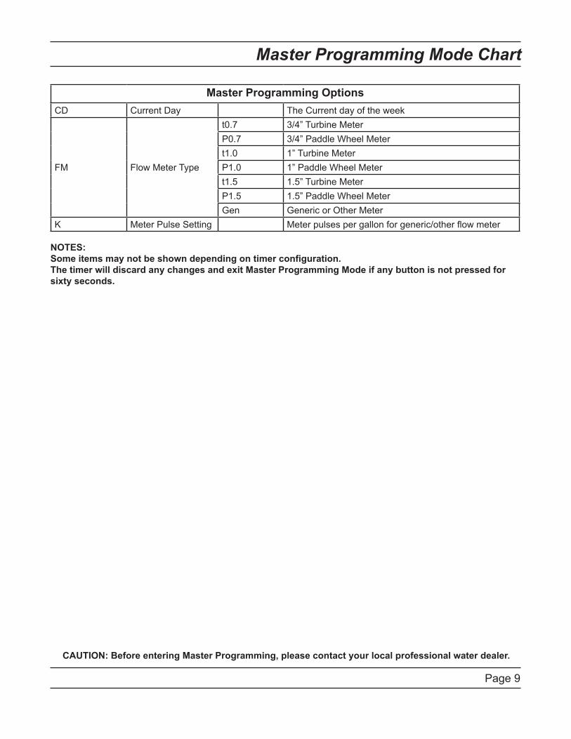
CD Current Day The Current day of the week
FM Flow Meter Type
t0.7 3/4” Turbine Meter
P0.7 3/4” Paddle Wheel Meter
t1.0 1” Turbine Meter
P1.0 1” Paddle Wheel Meter
t1.5 1.5” Turbine Meter
P1.5 1.5” Paddle Wheel Meter
Gen Generic or Other Meter
K Meter Pulse Setting Meter pulses per gallon for generic/other flow meter
NOTES:
Some items may not be shown depending on timer configuration.
The timer will discard any changes and exit Master Programming Mode if any button is not pressed for
sixty seconds.
Page 10
Master Programming Mode
CAUTION: Before entering Master Programming, please contact your local professional water dealer.
When the Master Programming Mode is entered, all available option setting displays may be viewed and set as
needed. Depending on current option settings, some parameters cannot be viewed or set.
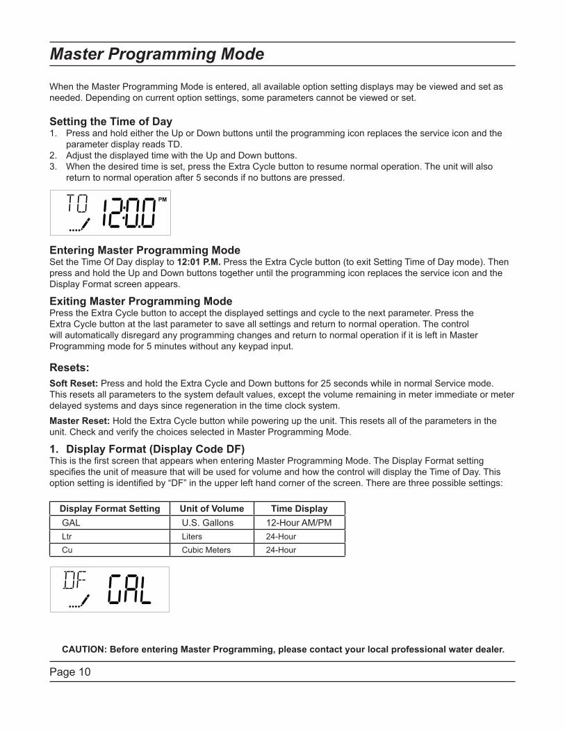
Setting the Time of DayPress and hold either the Up or Down buttons until the programming icon replaces the service icon and the 1.
parameter display reads TD.
Adjust the displayed time with the Up and Down buttons.2.
3. When the desired time is set, press the Extra Cycle button to resume normal operation. The unit will also
return to normal operation after 5 seconds if no buttons are pressed.
Entering Master Programming ModeSet the Time Of Day display to 12:01 P.M. Press the Extra Cycle button (to exit Setting Time of Day mode). Then
press and hold the Up and Down buttons together until the programming icon replaces the service icon and the
Display Format screen appears.
Exiting Master Programming ModePress the Extra Cycle button to accept the displayed settings and cycle to the next parameter. Press the
Extra Cycle button at the last parameter to save all settings and return to normal operation. The control
will automatically disregard any programming changes and return to normal operation if it is left in Master
Programming mode for 5 minutes without any keypad input.
Resets:
Soft Reset: Press and hold the Extra Cycle and Down buttons for 25 seconds while in normal Service mode.
This resets all parameters to the system default values, except the volume remaining in meter immediate or meter
delayed systems and days since regeneration in the time clock system.
Master Reset: Hold the Extra Cycle button while powering up the unit. This resets all of the parameters in the
unit. Check and verify the choices selected in Master Programming Mode.
1. Display Format (Display Code DF)This is the first screen that appears when entering Master Programming Mode. The Display Format setting
specifies the unit of measure that will be used for volume and how the control will display the Time of Day. This
option setting is identified by “DF” in the upper left hand corner of the screen. There are three possible settings:
Display Format Setting Unit of Volume Time Display
GAL U.S. Gallons 12-Hour AM/PM
Ltr Liters 24-Hour
Cu Cubic Meters 24-Hour

Page 11
Master Programming Mode
CAUTION: Before entering Master Programming, please contact your local professional water dealer.
2. Valve Type (Display Code VT)Press the Extra Cycle button. Use this display to set the Valve Type. The Valve Type setting specifies the type of
cycle that the valve follows during regeneration. Note that some valve types require that the valve be built with
specific subcomponents. Ensure the valve is configured properly before changing the Valve Type setting. This
option setting is identified by “VT” in the upper left hand corner of the screen. There are 5 possible settings:
Abbreviation Parameter
St1b Standard Downflow/Upflow, Single Backwash
St2b Standard Downflow/Upflow, Double Backwash
Fltr Filter
UFbF Upflow Brine First
8500 TwinFlo 100
Othr Other
3. Control Type (Display Code CT)Press the Extra Cycle button. Use this display to set the Control Type. This specifies how the control determines
when to trigger a regeneration. For details on how the various options function, refer to the “Timer Operation”
section of this service manual. This option setting is identified by “CT” in the upper left hand corner of the screen.
There are four possible settings:
Meter Delayed: Fd
Meter Immediate: FI
Time Clock: tc
Day of Week: dAY
4. Number of Tanks (Display Code NT)Press the Extra Cycle button. Use this display to set the Number of Tanks in your system. This option setting is
identified by “NT” in the upper left hand corner of the screen. There are two possible settings:
Single Tank System: 1
Two-Tank System: 2
Page 12
Master Programming Mode
CAUTION: Before entering Master Programming, please contact your local professional water dealer.
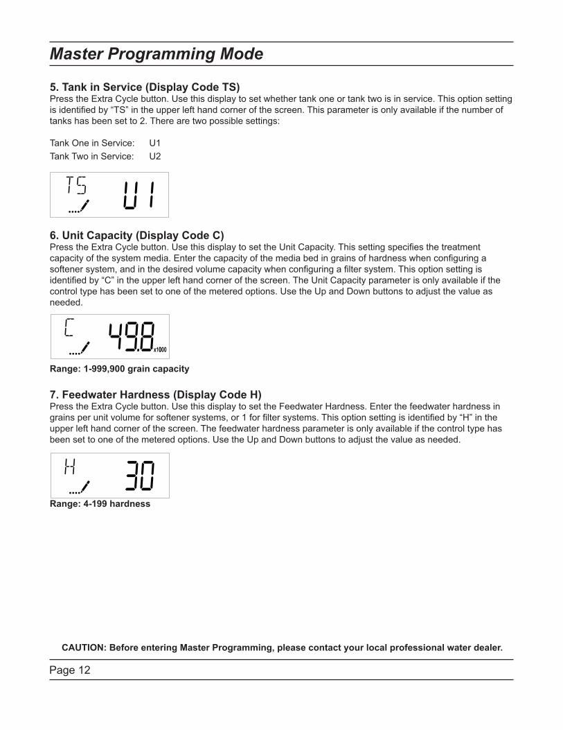
5. Tank in Service (Display Code TS)Press the Extra Cycle button. Use this display to set whether tank one or tank two is in service. This option setting
is identified by “TS” in the upper left hand corner of the screen. This parameter is only available if the number of
tanks has been set to 2. There are two possible settings:
Tank One in Service: U1
Tank Two in Service: U2
6. Unit Capacity (Display Code C)Press the Extra Cycle button. Use this display to set the Unit Capacity. This setting specifies the treatment
capacity of the system media. Enter the capacity of the media bed in grains of hardness when configuring a
softener system, and in the desired volume capacity when configuring a filter system. This option setting is
identified by “C” in the upper left hand corner of the screen. The Unit Capacity parameter is only available if the
control type has been set to one of the metered options. Use the Up and Down buttons to adjust the value as
needed.
Range: 1-999,900 grain capacity
7. Feedwater Hardness (Display Code H)Press the Extra Cycle button. Use this display to set the Feedwater Hardness. Enter the feedwater hardness in
grains per unit volume for softener systems, or 1 for filter systems. This option setting is identified by “H” in the
upper left hand corner of the screen. The feedwater hardness parameter is only available if the control type has
been set to one of the metered options. Use the Up and Down buttons to adjust the value as needed.
Range: 4-199 hardness
Page 13
Master Programming Mode
CAUTION: Before entering Master Programming, please contact your local professional water dealer.
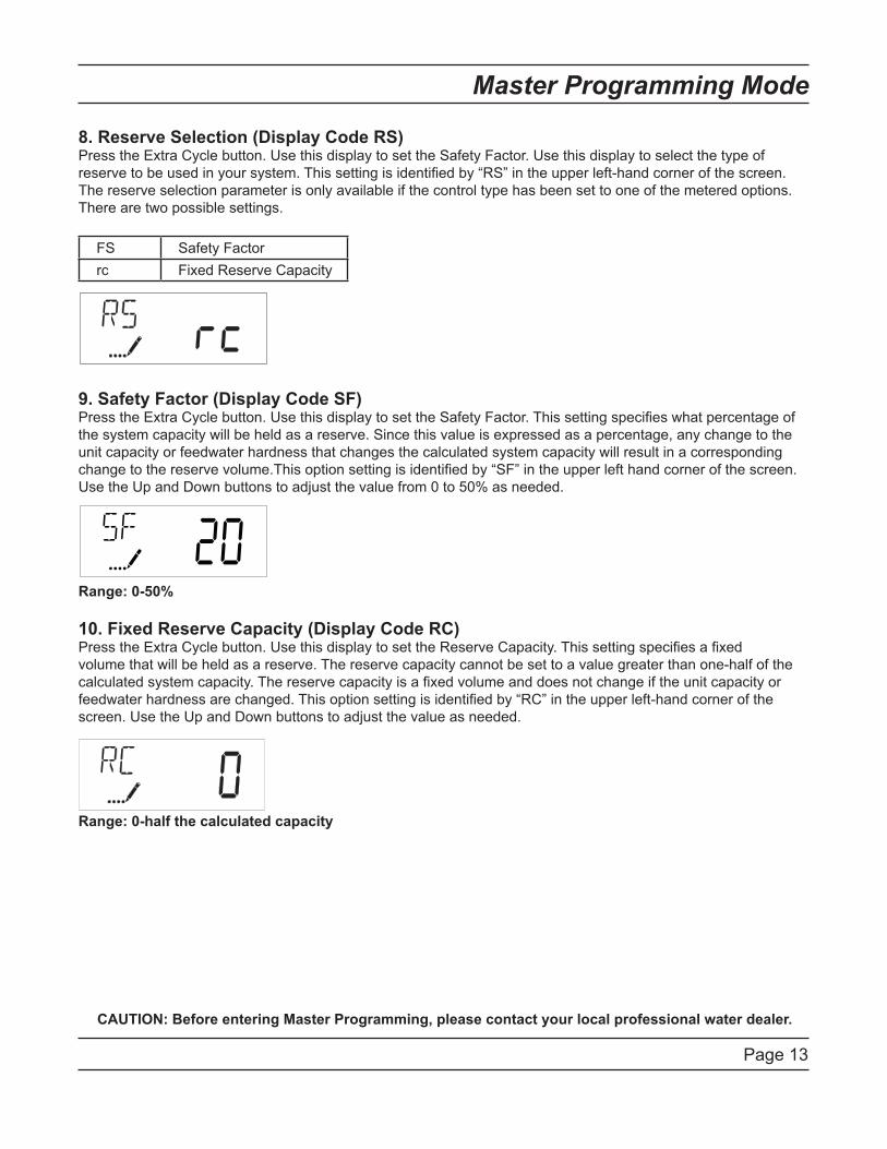
8. Reserve Selection (Display Code RS)Press the Extra Cycle button. Use this display to set the Safety Factor. Use this display to select the type of
reserve to be used in your system. This setting is identified by “RS” in the upper left-hand corner of the screen.
The reserve selection parameter is only available if the control type has been set to one of the metered options.
There are two possible settings.
FS Safety Factor
rc Fixed Reserve Capacity
9. Safety Factor (Display Code SF)Press the Extra Cycle button. Use this display to set the Safety Factor. This setting specifies what percentage of
the system capacity will be held as a reserve. Since this value is expressed as a percentage, any change to the
unit capacity or feedwater hardness that changes the calculated system capacity will result in a corresponding
change to the reserve volume.This option setting is identified by “SF” in the upper left hand corner of the screen.
Use the Up and Down buttons to adjust the value from 0 to 50% as needed.
Range: 0-50%
10. Fixed Reserve Capacity (Display Code RC)Press the Extra Cycle button. Use this display to set the Reserve Capacity. This setting specifies a fixed
volume that will be held as a reserve. The reserve capacity cannot be set to a value greater than one-half of the
calculated system capacity. The reserve capacity is a fixed volume and does not change if the unit capacity or
feedwater hardness are changed. This option setting is identified by “RC” in the upper left-hand corner of the
screen. Use the Up and Down buttons to adjust the value as needed.
Range: 0-half the calculated capacity
Page 14
Master Programming Mode
CAUTION: Before entering Master Programming, please contact your local professional water dealer.
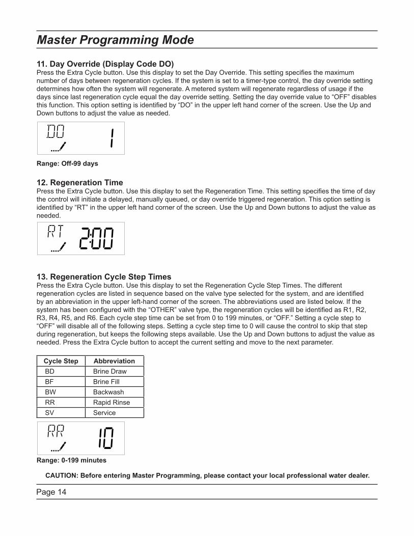
11. Day Override (Display Code DO)Press the Extra Cycle button. Use this display to set the Day Override. This setting specifies the maximum
number of days between regeneration cycles. If the system is set to a timer-type control, the day override setting
determines how often the system will regenerate. A metered system will regenerate regardless of usage if the
days since last regeneration cycle equal the day override setting. Setting the day override value to “OFF” disables
this function. This option setting is identified by “DO” in the upper left hand corner of the screen. Use the Up and
Down buttons to adjust the value as needed.
Range: Off-99 days
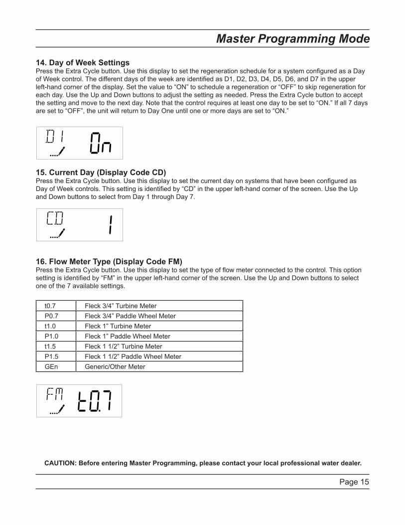
12. Regeneration TimePress the Extra Cycle button. Use this display to set the Regeneration Time. This setting specifies the time of day
the control will initiate a delayed, manually queued, or day override triggered regeneration. This option setting is
identified by “RT” in the upper left hand corner of the screen. Use the Up and Down buttons to adjust the value as
needed.
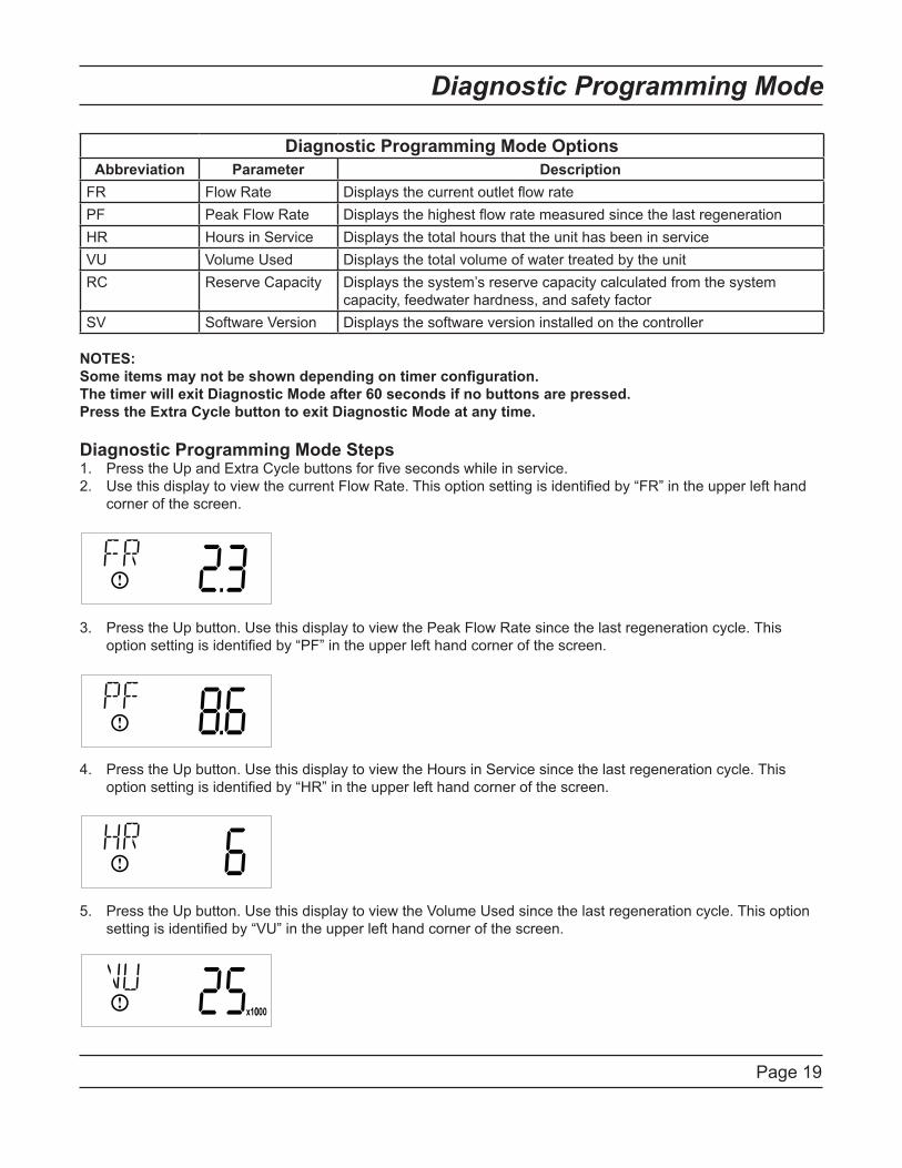
13. Regeneration Cycle Step TimesPress the Extra Cycle button. Use this display to set the Regeneration Cycle Step Times. The different
regeneration cycles are listed in sequence based on the valve type selected for the system, and are identified
by an abbreviation in the upper left-hand corner of the screen. The abbreviations used are listed below. If the
system has been configured with the “OTHER” valve type, the regeneration cycles will be identified as R1, R2,
R3, R4, R5, and R6. Each cycle step time can be set from 0 to 199 minutes, or “OFF.” Setting a cycle step to
“OFF” will disable all of the following steps. Setting a cycle step time to 0 will cause the control to skip that step
during regeneration, but keeps the following steps available. Use the Up and Down buttons to adjust the value as
needed. Press the Extra Cycle button to accept the current setting and move to the next parameter.
Cycle Step Abbreviation
BD Brine Draw
BF Brine Fill
BW Backwash
RR Rapid Rinse
SV Service
Range: 0-199 minutes
Page 15
Master Programming Mode
CAUTION: Before entering Master Programming, please contact your local professional water dealer.
14. Day of Week SettingsPress the Extra Cycle button. Use this display to set the regeneration schedule for a system configured as a Day
of Week control. The different days of the week are identified as D1, D2, D3, D4, D5, D6, and D7 in the upper
left-hand corner of the display. Set the value to “ON” to schedule a regeneration or “OFF” to skip regeneration for
each day. Use the Up and Down buttons to adjust the setting as needed. Press the Extra Cycle button to accept
the setting and move to the next day. Note that the control requires at least one day to be set to “ON.” If all 7 days
are set to “OFF”, the unit will return to Day One until one or more days are set to “ON.”
15. Current Day (Display Code CD)Press the Extra Cycle button. Use this display to set the current day on systems that have been configured as
Day of Week controls. This setting is identified by “CD” in the upper left-hand corner of the screen. Use the Up
and Down buttons to select from Day 1 through Day 7.
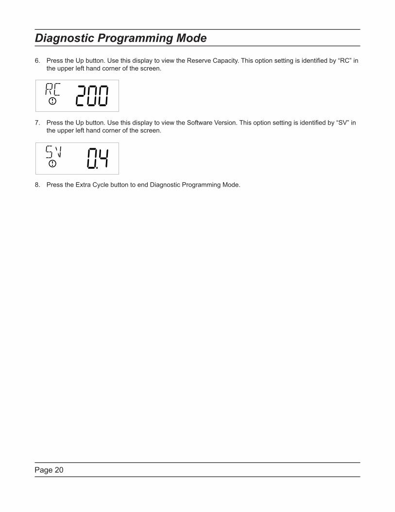
16. Flow Meter Type (Display Code FM)Press the Extra Cycle button. Use this display to set the type of flow meter connected to the control. This option
setting is identified by “FM” in the upper left-hand corner of the screen. Use the Up and Down buttons to select
one of the 7 available settings.
t0.7 Fleck 3/4” Turbine Meter
P0.7 Fleck 3/4” Paddle Wheel Meter
t1.0 Fleck 1” Turbine Meter
P1.0 Fleck 1” Paddle Wheel Meter
t1.5 Fleck 1 1/2” Turbine Meter
P1.5 Fleck 1 1/2” Paddle Wheel Meter
GEn Generic/Other Meter

Page 16
Master Programming Mode
17. Meter Pulse Setting (Display Code K)Press the Extra Cycle button. Use this display to specify the meter pulse setting for a non-standard flow meter.
This option setting is identified by “K” in the upper left-hand corner of the screen. Use the Up and Down buttons to
enter the meter constant in pulses per unit volume.
18. Press the Extra Cycle button to save all settings and exit Master Programming Mode.

Page 17
User Programming Mode
User Programming Mode Options
Abbreviation Parameter Description
DO Day Override The timer’s day override setting
RT Regeneration Time The time of day that the system
will regenerate (meter delayed,
timeclock, and day-of-week
systems)
H Feed Water Hardness The hardness of the inlet water -
used to calculate system capacity
for metered systems
RC Reserve Capacity The fixed reserve capacity
CD Current Day The current day of week
NOTES:
Some items may not be shown depending on timer configuration.
The timer will discard any changes and exit User Mode if any button is not pressed for sixty seconds.
User Programming Mode StepsPress the Up and Down buttons for five seconds while in service, and the time of day is NOT set to 12:01 PM.1.
Use this display to adjust the Day Override. This option setting is identified by “DO” in the upper left hand 2.
corner of the screen.
Press the Extra Cycle button. Use this display to adjust the Regeneration Time. This option setting is identified 3.
by “RT” in the upper left hand corner of the screen.
Press the Extra Cycle button. Use this display to adjust the Feed Water Hardness. This option setting is 4.
identified by “FH” in the upper left hand corner of the screen.
Range: 4-199 hardness

Page 18
Press the Extra Cycle button. Use this display to adjust the Fixed Reserve Capacity. This option setting is 5.
identified by “RC” in the upper left-hand Corner of the screen.
Press the Extra Cycle button. Use this display to set the Current Day of the Week. This option setting is 6.
identified by “CD” in the upper left hand corner of the screen.
Press the Extra Cycle button to end User Programming Mode.7.
User Programming Mode
Page 19
Diagnostic Programming Mode
Diagnostic Programming Mode Options
Abbreviation Parameter Description
FR Flow Rate Displays the current outlet flow rate
PF Peak Flow Rate Displays the highest flow rate measured since the last regeneration
HR Hours in Service Displays the total hours that the unit has been in service
VU Volume Used Displays the total volume of water treated by the unit
RC Reserve Capacity Displays the system’s reserve capacity calculated from the system
capacity, feedwater hardness, and safety factor
SV Software Version Displays the software version installed on the controller
NOTES:
Some items may not be shown depending on timer configuration.
The timer will exit Diagnostic Mode after 60 seconds if no buttons are pressed.
Press the Extra Cycle button to exit Diagnostic Mode at any time.
Diagnostic Programming Mode StepsPress the Up and Extra Cycle buttons for five seconds while in service.1.
Use this display to view the current Flow Rate. This option setting is identified by “FR” in the upper left hand 2.
corner of the screen.
Press the Up button. Use this display to view the Peak Flow Rate since the last regeneration cycle. This 3.
option setting is identified by “PF” in the upper left hand corner of the screen.
Press the Up button. Use this display to view the Hours in Service since the last regeneration cycle. This 4.
option setting is identified by “HR” in the upper left hand corner of the screen.
Press the Up button. Use this display to view the Volume Used since the last regeneration cycle. This option 5.
setting is identified by “VU” in the upper left hand corner of the screen.
Page 20
Diagnostic Programming Mode
Press the Up button. Use this display to view the Reserve Capacity. This option setting is identified by “RC” in 6.
the upper left hand corner of the screen.
Press the Up button. Use this display to view the Software Version. This option setting is identified by “SV” in 7.
the upper left hand corner of the screen.
Press the Extra Cycle button to end Diagnostic Programming Mode.8.
Page 21
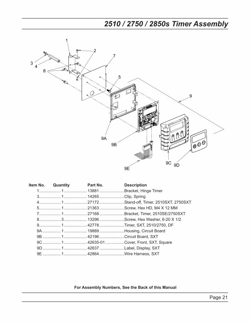
2510 / 2750 / 2850s Timer Assembly
Item No. Quantity Part No. Description
1 ................... 1 .................... 13881 ......................Bracket, Hinge Timer
3 ................... 1 .................... 14265 ......................Clip, Spring
4 ................... 1 .................... 27172 ......................Stand-off, Timer, 2510SXT, 2750SXT
5 ................... 1 .................... 21363 ......................Screw, Hex HD, M4 X 12 MM
7 ................... 1 .................... 27168 ......................Bracket, Timer, 2510SE/2750SXT
8 ................... 3 .................... 13296 ......................Screw, Hex Washer, 6-20 X 1/2
9 ................... 1 .................... 42778 ......................Timer, SXT, 2510/2750, DF
9A ................ 1 .................... 19889 ......................Housing, Circuit Board
9B ................ 1 .................... 42196 ......................Circuit Board, SXT
9C ................ 1 .................... 42635-01 .................Cover, Front, SXT, Square
9D ................ 1 .................... 42637 ......................Label, Display, SXT
9E ................ 1 .................... 42864 ......................Wire Harness, SXT
For Assembly Numbers, See the Back of this Manual
9
3 4
1
2
7
5
9A
9B
9C 9D
8
9E

Page 22
9000/9100/9500 Twin Tank Timer Assembly
Item No. Quantity Part No. Description
1 ................... 1 .................... 13881 ......................Bracket, Hinge Timer
2 ................... 2 .................... 11384 ......................Screw, Phillips, 6-32 X 1/4
3 ................... 1 .................... 42732 ......................Bracket, Timer, 9000SXT
4 ................... 2 .................... 13296 ......................Screw, Hex Washer Hd, 6-20 X 1/2
5 ................... 1 .................... 14265 ......................Clip, Spring
6 ................... 1 .................... 42733 ......................Stand-off, Timer, 9000SXT
7 ................... 1 .................... 42777 ......................Timer, SXT, D/F, 9000/9100/9500
7A ................ 1 .................... 19889 ......................Housing, Circuit Board
7B ................ 1 .................... 42196 ......................Circuit Board, SXT
7C ................ 1 .................... 42635-01 .................Cover, Front, SXT, Square
7D ................ 1 .................... 42637 ......................Label, Display, SXT
For Assembly Numbers, See the Back of this Manual
1
2
4
3
56
7A
7B
7C7D
7

Page 23
3/4” Plastic Turbine Meter Assembly
Item No. Quantity Part No. Description
1 ................... 1 .................... 19791-01 .................Meter Cable Assy, Turbine/SXT
2 ................... 2 .................... 19569 ......................Clip, Flow Meter
3 ................... 2 .................... 13314 ......................Screw, Slot Ind Hex, 8-18 x .60
For Assembly Numbers, See the Back of this Manual
Page 24
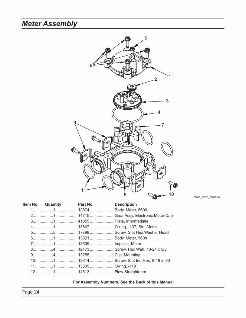
Meter Assembly
Item No. Quantity Part No. Description
1 ..................1 ...................13874 ......................Body, Meter, 5600
2 ..................1 ...................14715 ......................Gear Assy, Electronic Meter Cap
3 ..................1 ...................41055 ......................Plate, Intermediate
4 ..................1 ...................13847 ......................O-ring, -137, Std, Meter
5 ..................5 ...................17798 ......................Screw, Slot Hex Washer Head
6 ..................1 ...................13821 ......................Body, Meter, 5600
7 ..................1 ...................13509 ......................Impeller, Meter
8 ..................4 ...................12473 ......................Screw, Hex Wsh, 10-24 x 5/8
9 ..................4 ...................13255 ......................Clip, Mounting
10 ................1 ...................13314 ......................Screw, Slot Ind Hex, 8-18 x .60
11 ................1 ...................13305 ......................O-ring, -119
12 ................1 ...................14613 ......................Flow Straightener
For Assembly Numbers, See the Back of this Manual
60086_REVD_60086-50

Page 25
3/4” Brass Paddle Meter Assembly
Item No. Quantity Part No. Description
1 ................... 1 .................... 11206 ......................Gasket, Fitting
2 ................... 1 .................... 13942 ......................Retainer, Nut
3 ................... 1 .................... 11207 ......................Nut, Special, Quick Connect
4 ................... 1 .................... 13906 ......................Body, Meter, 3/4”
5 ................... 1 .................... 13509 ......................Impeller, Meter
13509-01 .................Impeller, Celcon
6 ................... 1 .................... 13847 ......................O-ring, -137 Std/560CD, Meter
7 ................... 1 .................... 14716 ......................Meter Cap Assy, ET/NT
8 ................... 1 .................... 12473 ......................Screw, Hex Wsh, 10-24 x 5/8
Not Shown .......................... 19121-08 .................Meter Cable Assy, NT, 35” w/Connector
19121-09 .................Meter Cable Assy, NT, 99.5” w/Connector
19121-10 .................Meter Cable Assy, NT, 303.5” w/Connector
For Assembly Numbers, See the Back of this Manual
Page 26
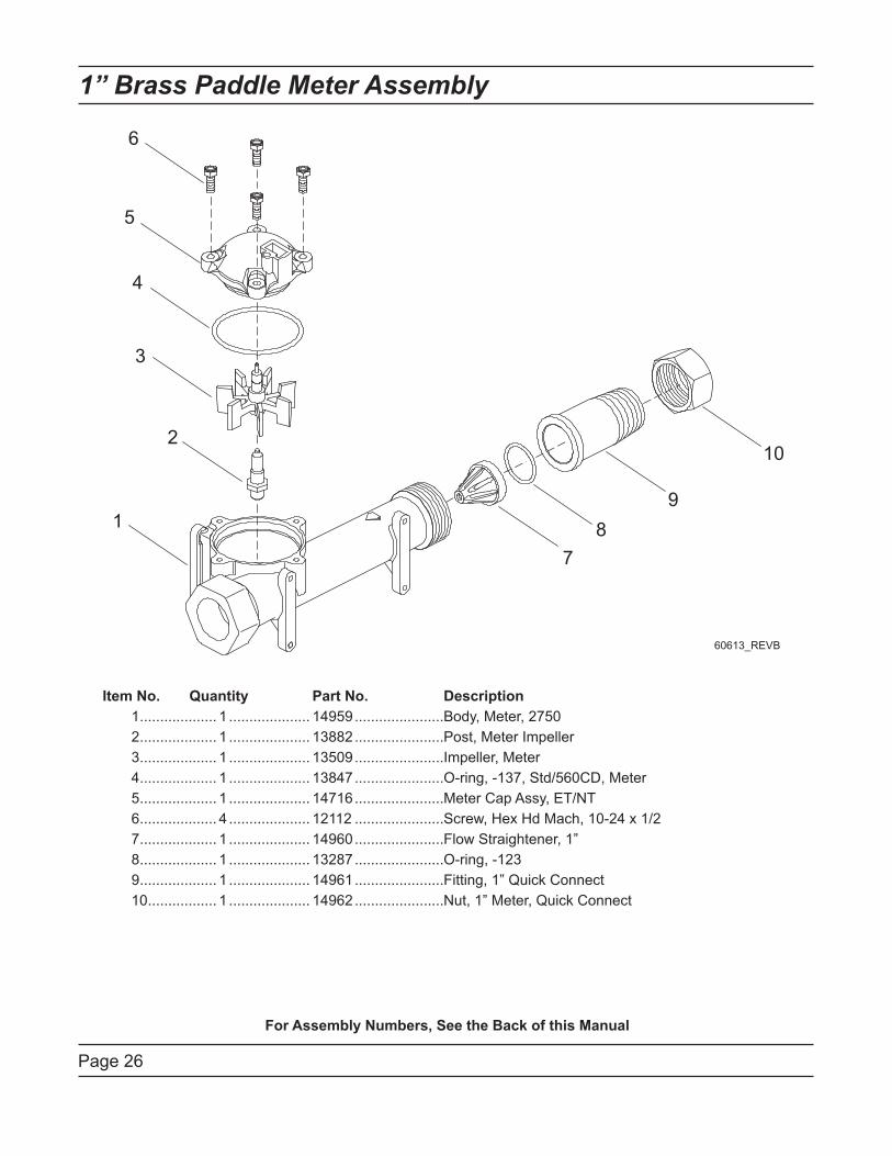
1” Brass Paddle Meter Assembly
Item No. Quantity Part No. Description
1 ................... 1 .................... 14959 ......................Body, Meter, 2750
2 ................... 1 .................... 13882 ......................Post, Meter Impeller
3 ................... 1 .................... 13509 ......................Impeller, Meter
4 ................... 1 .................... 13847 ......................O-ring, -137, Std/560CD, Meter
5 ................... 1 .................... 14716 ......................Meter Cap Assy, ET/NT
6 ................... 4 .................... 12112 ......................Screw, Hex Hd Mach, 10-24 x 1/2
7 ................... 1 .................... 14960 ......................Flow Straightener, 1”
8 ................... 1 .................... 13287 ......................O-ring, -123
9 ................... 1 .................... 14961 ......................Fitting, 1” Quick Connect
10 ................. 1 .................... 14962 ......................Nut, 1” Meter, Quick Connect
For Assembly Numbers, See the Back of this Manual

Page 27
Inline Plastic Turbine Meter Assembly
Item No. Quantity Part No. Description
1 ................... 1 .................... 17542 ......................Flow Straightener
2 ................... 2 .................... 40576 ......................Clip, H, Plastic, 7000
3 ................... 1 .................... 40577 ......................Turbine Meter Assy, 7000
4 ................... 1 .................... 41555 ......................Body, Remote Meter
5 ................... 2 .................... 40951 ......................O-ring, -220
6 ................... 2 .................... 40563 ......................Connector, 1” NPT, 7000
7 ................... 2 .................... 40563-10 .................Connector, 1” BSP, 7000
8 ................... 2 .................... 40565 ......................Connector, 1-1/4” NPT, 7000
9 ................... 2 .................... 40565-10 .................Connector, 1-1/4” BSP, 7000
10 ................. 2 .................... 41242 ......................Connector, 1” & 1-1/4” Sweat
11 ................. 2 .................... 41243 ......................Connector, 1-1/4 & 1-1/2” Sweat
12 ................. 2 .................... 41596 ......................Connector, Brass, 1” NPT
13 ................. 2 .................... 41596-10 .................Connector, Brass, 1” BSP
14 ................. 2 .................... 41597 ......................Connector, Brass, 1-1/2” NPT
15 ................. 2 .................... 41597-10 .................Connector, Brass, 1-1/2” BSP
For Assembly Numbers, See the Back of this Manual
Page 28
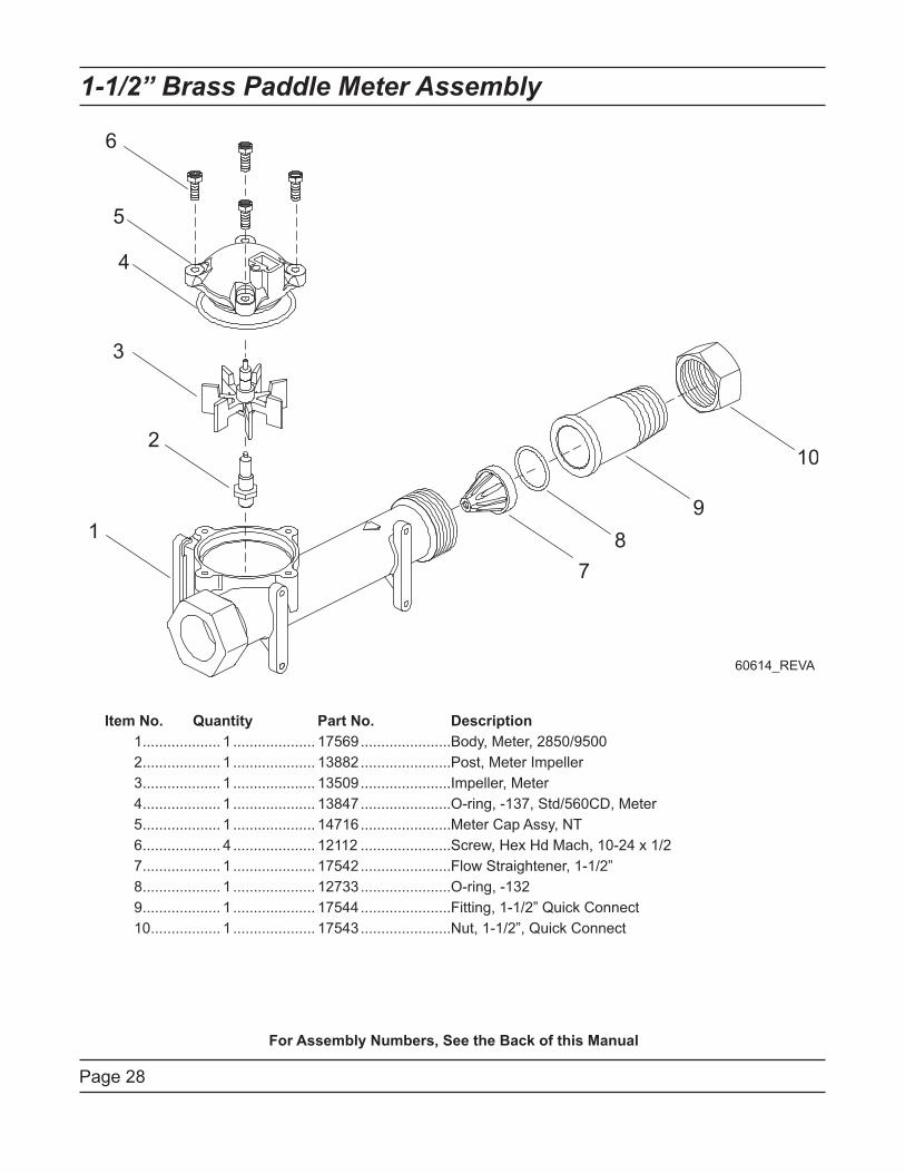
1-1/2” Brass Paddle Meter Assembly
Item No. Quantity Part No. Description
1 ................... 1 .................... 17569 ......................Body, Meter, 2850/9500
2 ................... 1 .................... 13882 ......................Post, Meter Impeller
3 ................... 1 .................... 13509 ......................Impeller, Meter
4 ................... 1 .................... 13847 ......................O-ring, -137, Std/560CD, Meter
5 ................... 1 .................... 14716 ......................Meter Cap Assy, NT
6 ................... 4 .................... 12112 ......................Screw, Hex Hd Mach, 10-24 x 1/2
7 ................... 1 .................... 17542 ......................Flow Straightener, 1-1/2”
8 ................... 1 .................... 12733 ......................O-ring, -132
9 ................... 1 .................... 17544 ......................Fitting, 1-1/2” Quick Connect
10 ................. 1 .................... 17543 ......................Nut, 1-1/2”, Quick Connect
For Assembly Numbers, See the Back of this Manual
Page 29
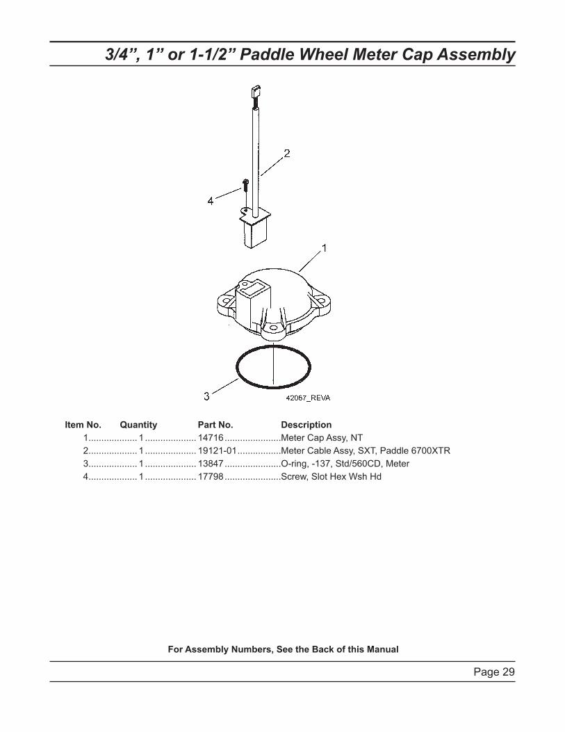
3/4”, 1” or 1-1/2” Paddle Wheel Meter Cap Assembly
Item No. Quantity Part No. Description
1 ................... 1 .................... 14716 ......................Meter Cap Assy, NT
2 ................... 1 .................... 19121-01 .................Meter Cable Assy, SXT, Paddle 6700XTR
3 ................... 1 .................... 13847 ......................O-ring, -137, Std/560CD, Meter
4 ................... 1 .................... 17798 ......................Screw, Slot Hex Wsh Hd
For Assembly Numbers, See the Back of this Manual

Page 3
0
251
0S
XT
Wirin
g D
iag
ram
SCAM
HCAM
C
N.O
.
N.C
.SW
2
C
N.O
.
N.C
.SW
1VDM
T1
H - - S
WH
ITE
N N
GR
EE
N
TM
PU
RP
LE
OR
AN
GE
WHITE
YEL
S
PWR VDO METER+
BLUE
WT/BLK
BLU
E
BLA
CK
H N.O.
P2
RE
D
BLA
CK
P1
BLA
CK
OR
AN
GE
BLA
CK
PU
RP
LE
WT/
BLK
YE
LLO
W
WHITE (BLUE)
H/S
BLACK (BROWN)
BACKPLATE
GROUND
SCREW
GREEN/YELLOW
CB1 - SXT TIMERT1 - 24VAC TRANSFORMERK1 - 24VAC VALVE DRIVE RELAYTM - 3/4" TURBINE FLOW METER (OPTIONAL)VDM - VALVE DRIVE MOTORSW1 - VALVE HOMING SWITCHSW2 - VALVE STEP SWITCHHCAM - VALVE HOMING CAMSCAM - VALVE STEP CAM
NOTE:DEPENDING ON APPLICATION, VALVE STEP CAM APPEARANCE WILL VARY.1.REGARDLESS OF CAM TYPE USED, WIRING TO SWITCHES SW1 AND SW2 2.WILL REMAIN AS SHOWN.VALVE SHOWN IN SERVICE POSITION.3.
CB150/60 HZ
42741
Page 3
1
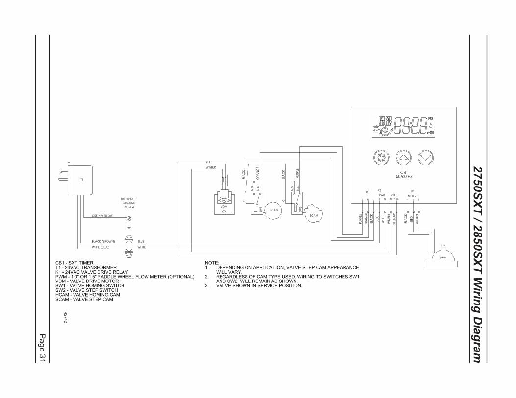
2750S
XT
/ 2850S
XT
Wirin
g D
iag
ram
SCAM
HCAM
C
N.O
.
N.C
.SW
2
C
N.O
.
N.C
.SW
1VDM
PWM
1.0"
T1
H - - S
WH
ITE
N N
GR
EE
N
PU
RP
LE
OR
AN
GE
WHITE
YEL
S
PWR VDO METER+
BLUE
WT/BLK
BLU
E
BLA
CK
H N.O.
P2
RE
D
BLA
CK
P1
BLA
CK
OR
AN
GE
BLA
CK
PU
RP
LE
WT/
BLK
YE
LLO
W
WHITE (BLUE)
H/S
BLACK (BROWN)
BACKPLATE
GROUND
SCREW
GREEN/YELLOW
CB150/60 HZ
CB1 - SXT TIMERT1 - 24VAC TRANSFORMERK1 - 24VAC VALVE DRIVE RELAYPWM - 1.0" OR 1.5" PADDLE WHEEL FLOW METER (OPTIONAL)VDM - VALVE DRIVE MOTORSW1 - VALVE HOMING SWITCHSW2 - VALVE STEP SWITCHHCAM - VALVE HOMING CAMSCAM - VALVE STEP CAM
NOTE:DEPENDING ON APPLICATION, VALVE STEP CAM APPEARANCE 1.WILL VARY.REGARDLESS OF CAM TYPE USED, WIRING TO SWITCHES SW1 2.AND SW2 WILL REMAIN AS SHOWN.VALVE SHOWN IN SERVICE POSITION.3.
42742
Page 32
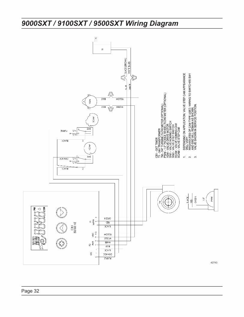
9000SXT / 9100SXT / 9500SXT Wiring Diagram
42743

Page 33
Troubleshooting
Error Codes
Note: Error codes appear on the In Service display.
Error
Code
Error Type Cause Reset and Recovery
0 Cam Sense
Error
The valve drive took longer
than 6 minutes to advance to
the next regeneration position.
Unplug the unit and examine the powerhead. Verify
that all cam switches are connected to the circuit
board and functioning properly. Verify that the motor
and drive train components are in good condition
and assembled properly. Check the valve and verify
that the piston travels free.y. Replace/reassemble
the various components as necessary.
Plug the unit back in and observe its behavior. The
unit should cycle to the next valve position and stop.
If the error re-occurs, unplug the unit and contact
technical support.
1 Cycle Step
Error
The control experienced an
unexpected cycle input
Unplug the unit and examine the powerhead.
Verify that all cam switches are connected to the
circuit board and functioning properly. Enter Master
Programming mode and verify that the valve type
and system type are set correctly with regard to the
unit itself.
Step the unit through a manual regeneration and
verify that it functions correctly. If the error re-occurs
unplug the unit and contact technical support.
2 Regen
Failure
The system has not
regenerated for more than 99
days (or 7 days if the Control
Type has been set to Day-of-
Week).
Perform a Manual Regeneration to reset the
error code. If the system is metered, verify that it
is measuring flow by running service water and
watching for the flow indicator on the display. If the
unit does not measure flow, verify that the meter
cable is connected properly and that the meter is
functioning properly.
Enter Master Programming mode and verify that the
unit is configured properly. As appropriate for the
valve configuration, check that the corrct system
capacity has been selected, that the day override is
set properly, and that the meter is identified correctly.
If the unit is configured as a Day-of-Week system,
verify that at least one days is set ON. Correct the
settings as necessary.
3 Memory
Error
Control board memory failure. Perform a Master Reset and reconfigure the system
via Master Programming mode. After reconfiguring
the system, set the valve through a manual
regeneration. If the rror re-occirs, unplug the unit and
contact technical support.
2 There
have been
more than
99 days
since
the last
Regeneration must occur for the unit to
recover, the display to clear and the valve
to function normally.
[ 7 - - 5 ]: To recover from [Err2], the user
must initiate a regeneration or set at least
one individual day to 1.
Page 34
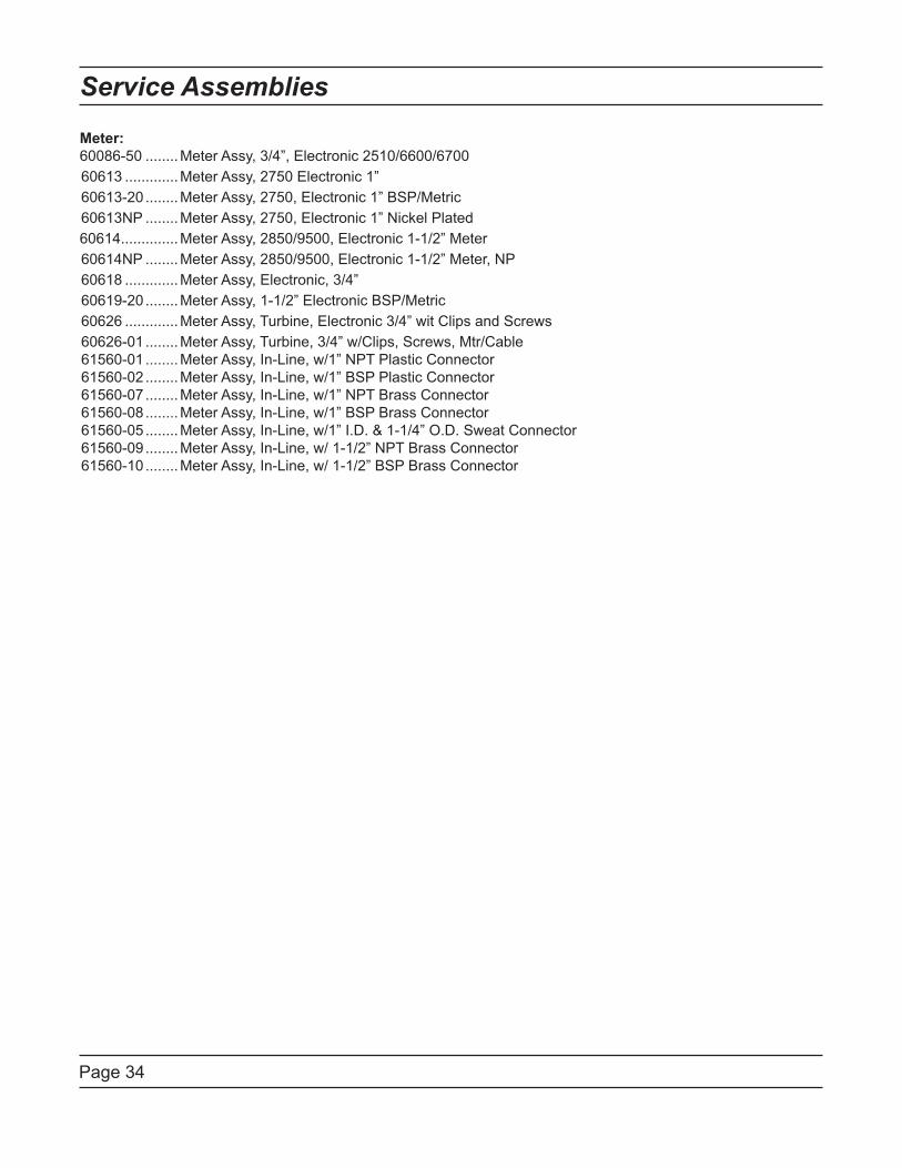
Service Assemblies
Meter:
60086-50 ........Meter Assy, 3/4”, Electronic 2510/6600/6700
60613 .............Meter Assy, 2750 Electronic 1”
60613-20 ........Meter Assy, 2750, Electronic 1” BSP/Metric
60613NP ........Meter Assy, 2750, Electronic 1” Nickel Plated
60614..............Meter Assy, 2850/9500, Electronic 1-1/2” Meter
60614NP ........Meter Assy, 2850/9500, Electronic 1-1/2” Meter, NP
60618 .............Meter Assy, Electronic, 3/4”
60619-20 ........Meter Assy, 1-1/2” Electronic BSP/Metric
60626 .............Meter Assy, Turbine, Electronic 3/4” wit Clips and Screws
60626-01 ........Meter Assy, Turbine, 3/4” w/Clips, Screws, Mtr/Cable
61560-01 ........Meter Assy, In-Line, w/1” NPT Plastic Connector
61560-02 ........Meter Assy, In-Line, w/1” BSP Plastic Connector
61560-07 ........Meter Assy, In-Line, w/1” NPT Brass Connector
61560-08 ........Meter Assy, In-Line, w/1” BSP Brass Connector
61560-05 ........Meter Assy, In-Line, w/1” I.D. & 1-1/4” O.D. Sweat Connector
61560-09 ........Meter Assy, In-Line, w/ 1-1/2” NPT Brass Connector
61560-10 ........Meter Assy, In-Line, w/ 1-1/2” BSP Brass Connector

P/N 42713 Rev. D 2/27/09