supplemental expert report original inquiry (coi 1)
TRANSCRIPT

Commission of Inquiry into the Construction Works at and near the Hung Hom Station Extension under the Shatin to Central Link Project (formerly Commission of Inquiry into the Diaphragm Wall and Platform Slab Construction Works at the Hung Hom Station Extension under the Shatin to Central Link Project) 6 December 2019
1
SUPPLEMENTAL EXPERT REPORT
ORIGINAL INQUIRY (COI 1)
PREPARED BY
PROFESSOR DON McQUILLAN
Expert Witness appointed by the Commission of Inquiry into the
Construction Works at and near the Hung Hom Station Extension
under the Shatin to Central Link Project (formerly Commission of
Inquiry into the Diaphragm Wall and Platform Slab Construction
Works at the Hung Hom Station Extension under the Shatin to
Central Link Project)
6 December 2019

Commission of Inquiry into the Construction Works at and near the Hung Hom Station Extension under the Shatin to Central Link Project (formerly Commission of Inquiry into the Diaphragm Wall and Platform Slab Construction Works at the Hung Hom Station Extension under the Shatin to Central Link Project)
Original Inquiry (CoI 1)
2
Professor Don McQuillan
Chartered Engineer specializing in Structural, Civil, Bridge & Marine Engineering;
Director of RPS
Specialist Field
Investigating and assessing defects and
failures in buildings and other structures,
arising from design and construction and
extraneous sources, as further detailed in
Appendix I
Appointed on behalf of
Commission of Inquiry into the Construction
Works at and near the Hung Hom Station
Extension under the Shatin to Central Link
Project (formerly Commission of Inquiry into
the Diaphragm Wall and Platform Slab
Construction Works at the Hung Hom
Station Extension under the Shatin to
Central Link Project) (The “Commission”)
Prepared for The Commission
On instructions of
Messrs. Lo & Lo, Solicitors for the
Commission (“Lo & Lo”)
Subject matter / Scope of
engagement:
To assist the Commission in discharging its
duties under the Expanded Terms of
Reference and by acting as an Expert
Witness in the Inquiry hearings
Documents I was given access to the documents in the
hearing bundles. References in the text of
this Report are references to pages in the
hearing bundles.
Analysis integral to this Report
prepared by the Author See Appendix II
Meetings, visits and inspections See Appendix III

Commission of Inquiry into the Construction Works at and near the Hung Hom Station Extension under the Shatin to Central Link Project (formerly Commission of Inquiry into the Diaphragm Wall and Platform Slab Construction Works at the Hung Hom Station Extension under the Shatin to Central Link Project)
Original Inquiry (CoI 1)
3
THE EXPANDED TERMS OF REFERENCE OF THE COMMISSION ARE AS
FOLLOWS:
Regarding the MTR Corporation Limited (‘MTRCL’)’s Contract No. 1112 (‘Contract’) of
the Shatin to Central Link Project:
(a) (1) in respect of the diaphragm wall and platform slab construction works at the
Hung Hom Station Extension,
(i) to inquire into the facts and circumstances surrounding the steel
reinforcement fixing works, including but not limited to those works at
locations that have given rise to extensive public concern about their safety
since May 2018;
(ii) to inquire into the facts and circumstances surrounding any other works
which raise concerns about public safety; and
(iii) to ascertain whether the works in (1)(i) and (ii) above were executed in
accordance with the Contract. If not, the reasons therefor and whether
steps for rectification have been taken;
(a) (2) in respect of the construction works at the North Approach Tunnels, the South
Approach Tunnels and the Hung Hom Stabling Sidings,
(i) to inquire into the facts and circumstances surrounding any problem
relating to the steel reinforcement fixing or concreting works, including
but not limited to any lack of proper inspection, supervision or
documentation of such works undertaken, any lack of proper testing of the
materials used for such works and of proper documentation of such testing,
and any deviation of such works undertaken from the designs, plans or
drawings accepted by the Highways Department or the Building Authority;
(ii) to inquire into the facts and circumstances surrounding any works or
matters which raise concerns about public safety or substantial works
quality; and
(iii) to ascertain whether the works and matters involved in (2)(i) and (ii) above
were executed in accordance with the Contract. If not, the reasons therefor
and whether steps for rectification have been taken;
(b) to review, in the light of (a) above,

Commission of Inquiry into the Construction Works at and near the Hung Hom Station Extension under the Shatin to Central Link Project (formerly Commission of Inquiry into the Diaphragm Wall and Platform Slab Construction Works at the Hung Hom Station Extension under the Shatin to Central Link Project)
Original Inquiry (CoI 1)
4
(i) the adequacy of the relevant aspects of the MTRCL’s project management and
supervision system, quality assurance and quality control system, risk
management system, site supervision and control system and processes,
system on reporting to Government, system and processes for communication
internally and with various stakeholders, and any other related systems,
processes and practices, and the implementation thereof; and
(ii) the extent and adequacy of the monitoring and control mechanisms of the
Government, and the implementation thereof; and
(c) in the light of (b) above, to make recommendations on suitable measures with a
view to promoting public safety and assurance on quality of works.

Commission of Inquiry into the Construction Works at and near the Hung Hom Station Extension under the Shatin to Central Link Project (formerly Commission of Inquiry into the Diaphragm Wall and Platform Slab Construction Works at the Hung Hom Station Extension under the Shatin to Central Link Project)
Original Inquiry (CoI 1)
5
THE COMMISSION'S DIRECTIONS ON STRUCTURAL ENGINEERING EXPERT
EVIDENCE ISSUED ON 29 AUGUST 2019 [OU7/9691-9692]
(Relevant extracts only)
“3. A soft copy of the Southward COI 1 Report (as defined in Messrs Lo & Lo’s letter of 9
August 2019 [OU5/3416] and limited to the list of issues submitted under Messrs
O’Melveny’s letter of 16 August 2019 [OU6/3738-3739](“Issues 1”)) shall be produced
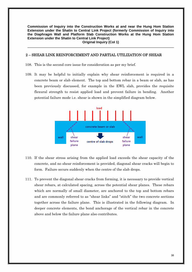
by Leighton to the Commission’s solicitors by 5:00 pm on Monday, 30 September
2019. The deadline for the submission of the Southward COI 1 Report as stated in
paragraph 4 of Messrs Lo & Lo’s said letter [OU5/3417] shall be varied accordingly.
.....
5. Leave shall be given to MTRCL and the Government to file an SE expert report
respectively in COI 1 ... on Issues 1 ... and in response to the Southward COI 1 Report ...
adduced under paragraph 3 ... above. A soft copy of such SE expert reports shall be
produced by MTRCL and the Government to the Commission’s solicitors by 5:00 pm
on Friday, 6 December 2019.
6. No further SE expert reports may be adduced without the leave of the Commission.
Kindly note that expert [report] of Professor Don McQuillan on matters concerning ... the
Holistic Report ... will also be submitted to the Commission on 6 December 2019.”
THE COMMISSION'S DIRECTIONS ON STRUCTURAL ENGINEERING EXPERT
EVIDENCE ISSUED ON 20 SEPTEMBER 2019 [OU7/9970]
“1. A short extension of time is allowed for Leighton to file the Southward COI 1 Report ....
2. A soft copy of such expert report shall be produced by Leighton to the Commission’s
solicitors by 5:00 pm on Friday, 11 October 2019.”

Commission of Inquiry into the Construction Works at and near the Hung Hom Station Extension under the Shatin to Central Link Project (formerly Commission of Inquiry into the Diaphragm Wall and Platform Slab Construction Works at the Hung Hom Station Extension under the Shatin to Central Link Project)
Original Inquiry (CoI 1)
6
THE COMMISSION'S FURTHER DIRECTIONS ON STRUCTURAL
ENGINEERING EXPERT EVIDENCE ISSUED ON 12 OCTOBER 2019 [OU8/10561-
10562]
1. The Commission’s directions on the filing of SE expert evidence in ... COI 1 ... as set
out in Messrs Lo & Lo’s emails dated 29 August 2019 [OU7/9691-9692] ... and 20
September 2019 [OU7/9968-9970] ... shall stand.
2. It is further directed, however, that in relation to the SE Expert evidence to be adduced
pursuant paragraph 1 above:
(a) the SE experts should focus on whether the as-constructed works are safe and
fit for purpose from a structural engineering perspective; and only if they are
considered not safe or fit for purpose that such experts should then provide
their opinion on whether the suitable measures (as agreed in the Holistic
Report ... or subsequently) are necessary for safety from a structural
engineering perspective; and
(b) the SE experts shall not be required to look into the question of whether the
suitable measures (as agreed in the Holistic Report ... or subsequently) are
required for statutory or code compliance.

Commission of Inquiry into the Construction Works at and near the Hung Hom Station Extension under the Shatin to Central Link Project (formerly Commission of Inquiry into the Diaphragm Wall and Platform Slab Construction Works at the Hung Hom Station Extension under the Shatin to Central Link Project)
Original Inquiry (CoI 1)
7
INSTRUCTIONS
In relation to the Original Inquiry, I have been instructed to give my opinion on the
matters under paragraph (a)(1) of the Terms of Reference. I have adduced my first
Expert Report on 6 January 2019 (my “First Report”) [ER 1/Item 3]. In addition, I have
been asked to review and comment on the Holistic Report1 [OU5/3229-3350] issued by
MTRCL dated 18 July 2019.
I am asked to:
(1) respond to the Southward COI 1 Report [ER2/Item 14] and the 3 principal topics
therein, namely:
Coupler connections/coupler engagement
Shear link reinforcement and partial utilization of shear; and
The horizontal construction joint (CJ) in the EWL slab-to-D-wall connection; and
(2) comply with the Commission’s Directions of 12 October 2019.
1 Final Report on Holistic Assessment Strategy for the Hung Hom Station Extension

Commission of Inquiry into the Construction Works at and near the Hung Hom Station Extension under the Shatin to Central Link Project (formerly Commission of Inquiry into the Diaphragm Wall and Platform Slab Construction Works at the Hung Hom Station Extension under the Shatin to Central Link Project)
Original Inquiry (CoI 1)
8
Expert’s Declaration
I, PROFESSOR DON McQUILLAN DECLARE THAT:
1. I declare and confirm that I have read the Code of Conduct for Expert Witnesses
as set out in Appendix D to the Rules of High Court, Cap. 4A and agree to be
bound by it. I understand that my duty in providing this written report and
giving evidence is to assist the Commission. I confirm that I have complied and
will continue to comply with my duty.
2. I know of no conflict of interests of any kind, other than any which I have
disclosed in my report.
3. I do not consider that any interest which I have disclosed affects my suitability as
an expert witness on any issues on which I have given evidence.
4. I will advise the Commission if, between the date of this Report and the hearing
of the Commission, there is any change in circumstances which affect my opinion
given to the Commission.
5. I have been shown the sources of all information I have used.
6. I have exercised reasonable care and skill in order to be accurate and complete in
preparing this report.
7. I have endeavoured to include in my report those matters, of which I have
knowledge or of which I have been made aware, that might adversely affect the
validity of my opinion. I have clearly stated any qualifications to my opinion.
8. I have not, without forming an independent view, included or excluded anything
which has been suggested to me by others, including my instructing solicitors.

Commission of Inquiry into the Construction Works at and near the Hung Hom Station Extension under the Shatin to Central Link Project (formerly Commission of Inquiry into the Diaphragm Wall and Platform Slab Construction Works at the Hung Hom Station Extension under the Shatin to Central Link Project)
Original Inquiry (CoI 1)
9
9. I will notify those instructing me immediately and confirm in writing if, for any
reason, my existing report requires any correction or qualification.
10. I understand that:
(a) my report will form the evidence to be given under oath or affirmation;
(b) questions may be put to me in writing for the purposes of clarifying my
report and that my answers shall be treated as part of my report and
covered by my statement of truth;
(c) the Commission may at any stage direct a discussion to take place between
the experts for the purpose of identifying and discussing the issues to be
investigated under the Terms of Reference, where possible reaching an
agreed opinion on those issues and identifying what action, if any, may be
taken to resolve any of the outstanding issues between the parties;
(d) the Commission may direct that following a discussion between the
experts that a statement should be prepared showing those issues which
are agreed, and those issues which are not agreed, together with a
summary of the reasons for disagreeing;
(e) I may be required to attend the hearing of the Commission to be cross-
examined on my report by Counsel of other party/parties;
(f) I am likely to be the subject of public adverse criticism by the Chairman
and Commissioners of the Commission if the Commission concludes that I
have not taken reasonable care in trying to meet the standards set out
above.
Commission of Inquiry into the Construction Works at and near the Hung Hom Station Extension under the Shatin to Central Link Project (formerly Commission of Inquiry into the Diaphragm Wall and Platform Slab Construction Works at the Hung Hom Station Extension under the Shatin to Central Link Project)
Original Inquiry (CoI 1)
10
Statement of Truth
I confirm that I have made clear which facts and matters referred to in this report are
within my own knowledge and which are not. Those that are within my own knowledge
I confirm to be true. I believe that the opinions expressed in this report are honestly
held.
Professor Don McQuillan
6 December 2019

Commission of Inquiry into the Construction Works at and near the Hung Hom Station Extension under the Shatin to Central Link Project (formerly Commission of Inquiry into the Diaphragm Wall and Platform Slab Construction Works at the Hung Hom Station Extension under the Shatin to Central Link Project)
Original Inquiry (CoI 1)
11
BACKGROUND
1. The Hearing for the Original Inquiry concluded in January 2019 with several
matters still under investigation and consideration by the Government and MTRCL,
including:
a) The opening-up and in-situ testing of the engagement lengths of coupler
assemblies
b) The strength of partially engaged coupler assemblies
c) The structural adequacy of the top east EWL slab-to-D-wall connections
d) Miscellaneous repairable defects and, in particular, shear link irregularities in
the EWL slab
2. My First Report dated 6 January 2019 dealt only with Areas B and C and in
particular with Area C where malpractice had been alleged [ER1/Item 3/§26]. It
highlighted several key issues in arriving at a conclusion on the safety of the
structures, namely:
a) Structural utilization throughout is generally low resulting in a significant
reserve of strength in the various elements [§§33-41 and §89].
b) Dead load accounts for some 90% of the total load and in service live load for
only 10% [§33].
c) The structures have already been subjected to a significant part of the live load
i.e. the testing and commission of trains [§6].
d) There is no visual evidence of any distress or cracking in any of the structural
elements [§107].
e) Ductile-grade couplers are not required where used in the EWL slab to D-wall
joint because the geometry of the connection between the EWL slab and the
east D-wall is so rigid that it precludes any ductility. The structural “plastic”
deformation which might occur during seismic activity will develop lower down

Commission of Inquiry into the Construction Works at and near the Hung Hom Station Extension under the Shatin to Central Link Project (formerly Commission of Inquiry into the Diaphragm Wall and Platform Slab Construction Works at the Hung Hom Station Extension under the Shatin to Central Link Project)
Original Inquiry (CoI 1)
12
the D-wall. In other words normal couplers could have been used in this
location [§89.2].
f) The top of the EWL slab at each D-wall is always in tension and the bottom is
always in compression [§30]. Conversely, for the NSL slab the top at each D-
wall is always in compression and the bottom is always in tension [§107].
g) From the perspective of structural adequacy, no bottom couplers are required
in the EWL slab and no top couplers in the NSL slab [§91].
h) To comply with code requirements in respect of seismicity/ductility only a
maximum of 50% of the EWL bottom and NSL top coupled connections are
required [§89.3].
3. On the basis of all the evidence available my First Report concluded [§126] that:
a) The structural integrity of the EWL and NSL slabs had not been compromised,
as a result of changes of detail and sub-standard workmanship incidents, and
that there were no safety issues or concerns.
b) Code compliance had been achieved in respect of ductility.
COUPLER IN-SITU TESTING
4. Around the time when the hearing of the Original Inquiry ended, the original PAUT
(Phased Array Ultrasonic Testing) proved, as suspected by the variable results, to be
inaccurate and unreliable. This resulted in a refinement to the methodology,
following which all the opened-up samples were re-tested under the enhanced PAUT
and the full programme of testing outlined in the Holistic Proposal was completed.
5. The full results of the enhanced PAUT are contained in Appendix B3 [OU5/3308-
3319] of the Holistic Report.
6. The acceptance criteria stated by the HyD2 [OU1/584] was for:
2 Holistic Assessment Strategy for Hung Hom Station Extension Stage 2 Investigation – Results
of Verification of Workmanship Quality for Coupler Connections dated 29 January 2019.

Commission of Inquiry into the Construction Works at and near the Hung Hom Station Extension under the Shatin to Central Link Project (formerly Commission of Inquiry into the Diaphragm Wall and Platform Slab Construction Works at the Hung Hom Station Extension under the Shatin to Central Link Project)
Original Inquiry (CoI 1)
13
A maximum of two full threads exposed i.e. 8mm; and
A minimum engagement of 40mm i.e. 10 threads with an allowable tolerance,
due to the Enhanced PAUT technique, of 3mm, i.e. almost one T40 thread,
giving a minimum acceptable engagement length of 37mm.
7. The explanation for this tolerance is stated in the revised method statement no. MS-
155 of AES Destructive & Non-Destructive Testing Ltd at 7.43 [OU2/896] as “…this
testing may involve an error of +/- 3mm.” It is difficult to comprehend, however, how
a method, which reports results to an accuracy of one tenth of one mm can be subject
to a tolerance of 3mm.
8. Notwithstanding, validation of enhanced PAUT readings was carried out against
Police actual measurements from unscrewed samples4[OW34-35][OW53]. Table 2
[OW53] shows that 5 valid samples in Stage 2 and 6 valid samples in Stage 3 were,
according to the Police, within the 3mm tolerance criteria leading to the conclusion
at §5.1 [OW35] that “…the enhanced method statement for PAUT is effective and
reliable for measuring the embedded length of threaded bar in a coupler within +/-
3mm tolerance.”
MTRCL partially engaged coupler testing
9. MTRCL subsequently proceeded to carry out a comprehensive suite of tests on
partially-engaged couplers using two different HOKLAS approved centres:
The MTR Corporation Project Laboratory (“MTR Lab”); and
Geotechnics & Concrete Engineering (H.K.) Ltd (“GCE”)
10. The coupler assembly tests comprised:
Tensile strength test (MTR Lab and GCE)[OU2/ 907.30-32][OU2/ 907.34-39]
3 Investigation Report on the issue of discrepancies found in PAUT on site assessment of coupler
connections 4 MTRCL Executive Summary for the event of discrepancies found in Phased Array Ultrasonic
Testing on site assessment of coupler connections dated 13 March 2019

Commission of Inquiry into the Construction Works at and near the Hung Hom Station Extension under the Shatin to Central Link Project (formerly Commission of Inquiry into the Diaphragm Wall and Platform Slab Construction Works at the Hung Hom Station Extension under the Shatin to Central Link Project)
Original Inquiry (CoI 1)
14
Permanent elongation test (MTR Lab and GCE) [OU2/907.30-
32][OU2/907.34-39]
Cyclic tension and compression test (GCE) [OU2/ 907.44-45, 907.46-61]
Static compression test (GCE) [OU2/ 907.45]
The formal test reports from MTR Lab and GCE may be found at OW1/91-119,
OW1/239-268.
11. By way of recap, BOSA5[A1/556-684] show the total threaded length of a T40 bar end
[A1/595] as 44mm (“t”) plus a tolerance of 4mm (“TOL”) i.e. a total of 48mm. This
appears to be at variance with the statement at 3 of their SUMMARY [A1/594]
where they state “Under normal circumstances, we provide a positive tolerance of
half a thread.” BOSA’s diagram [A1/595] shows a flat end on the threaded section of
the bar and it appears that this is schematic only and that, in effect, as will be
demonstrated next that the threaded length shown includes the bar end chamfer.
12. It is important, in the context of the enhanced PAUT testing methodology, to
understand the terminology used and the relationship between the term
“engagement” and the number of threads “effectively” engaged inside the coupler as
now used consistently in the various test reports6 [OU2/907.7-907.10]. The following
sketch diagram which I have prepared shows the presence of a positive chamfer at
the end of the threaded steel bars. It is not detailed enough to show a half-thread at
the bar end which is discounted (and therefore not “effective”) in terms of the
structural contribution of the threads. By way of explanation, when the PAUT
signal picks up the first thread (next to the bar end chamfer) the reading (from the
start of the chamfer) can be between 0-4mm (1 thread) depending on the bar rotation
and the thread start point. My understanding, therefore, is that the average part-
first thread is taken i.e.2mm (0.5 thread).
5 BOSA Technical and Quality Assurance Manual 6 MTRCL’s letter to HyD dated 15 February 2019

Commission of Inquiry into the Construction Works at and near the Hung Hom Station Extension under the Shatin to Central Link Project (formerly Commission of Inquiry into the Diaphragm Wall and Platform Slab Construction Works at the Hung Hom Station Extension under the Shatin to Central Link Project)
Original Inquiry (CoI 1)
15
13. In an equal “butt-to-butt” connection, 10 “effective” threads inside a coupler equates
to a “44mm engagement” i.e. [(10 threads)(4mm) + 2mm internal bar chamfer +
2mm bar end ineffective half-thread]. Similarly:
9 threads = 40mm engagement
8 threads = 36mm engagement
7 threads = 32mm engagement
6 threads = 28mm engagement
14. Both laboratories tested nine samples (a total of 18 no.) for each of:
6 thread engagement
7 thread engagement
8 thread engagement
15. The GCE results [OU907.34-39][OU907.45][OU907.47-50][OU907.55-62] and the
MTR Lab results [OU907.7-10][OU907.30-32] taken together, demonstrate that a 6

Commission of Inquiry into the Construction Works at and near the Hung Hom Station Extension under the Shatin to Central Link Project (formerly Commission of Inquiry into the Diaphragm Wall and Platform Slab Construction Works at the Hung Hom Station Extension under the Shatin to Central Link Project)
Original Inquiry (CoI 1)
16
thread engagement (28mm) is an unreliable acceptance criterion because the full
tensile strength is not achieved in any of the samples tested.
16. A 7 thread engagement very nearly passes with 12 out of the 18 achieving the full
tensile strength. There were three coupler failures and three thread failures.
17. An 8 thread engagement, however, consistently achieved the full tensile capacity of
the grade 460 rebar with the fracture occurring every time in the bar as intended.
18. By interpolation it is therefore reasonable to assume that a 7.5 thread engagement
(34mm) also achieves full tensile capacity. This was, in fact the acceptance
threshold which I used originally. It was based on a least engagement of 32mm in
the safety critical EWL top slab-to-D-wall connection as identified by the erroneous
original PAUT results. It is not unreasonable then to review the enhanced PAUT
results based on a conservative minimum engagement of 34mm (7.5 threads).
19. Only one MTR Lab sample out of 27 and, similarly, one GCE sample out of 27
passed the permanent elongation test criterion of 0.1mm. This test measures the
non-recoverable stretch of the bar at 0.6 times the characteristic strength/load. I
suspect that rather than elongation of the bar occurring, the recorded movement is
due to initial thread slippage of the laboratory-generated samples. In a fully
engaged “butt-to-butt” laboratory situation, the bar threads lock into the coupler
threads imparting a small amount of pre-load. On site, if a partially engaged bar is
screwed into the coupler until resistance is met, the threads still lock and, in my
opinion, prevent initial slippage.
20. In the partially engaged laboratory situation, however, the initial very small amount
of “slack” is taken-up as the tensile load is applied. Because utilization is generally
low, the EWL top rebars are operating at low stress levels so, from a structural
performance and safety perspective, the permanent elongation test is irrelevant.
21. If any such slippage occurred, it would only be regarded as significant if hairline-
minor cracking was evident in the top of the EWL slab at the D-wall connection
running parallel with the underlying-wall in those 10 panels where top coupled
connections were used. The inspections carried out to-date have yielded no evidence
of any such cracking. Even if it had occurred the cracking would not progress and is

Commission of Inquiry into the Construction Works at and near the Hung Hom Station Extension under the Shatin to Central Link Project (formerly Commission of Inquiry into the Diaphragm Wall and Platform Slab Construction Works at the Hung Hom Station Extension under the Shatin to Central Link Project)
Original Inquiry (CoI 1)
17
in an internal environment so as not to allow water penetration into the underlying
rebar and compromise durability. It should also be emphasised that coupler
assemblies tested “free” in the laboratory will behave differently and give more
conservative results than couplers which are encapsulated in concrete.
22. In respect of the GCE cyclic tension and compression tests, the results [OU2/907.45-
62] show that a 6-thread (28mm) engagement was unacceptable whereas an 8-
thread (36mm) engagement passed. For a 7-thread (32mm) engagement, seven out
of the nine tests passed with two samples exhibiting screw thread and/or coupler
failure. The cyclic test is one based on metal fatigue. In other words fatigue failure
of a steel rebar can occur if operating at high stress levels over a high number of
tension and compression load reversals. This test is therefore not relevant to the
EWL or NSL slabs because stress reversal will never be experienced. Fatigue failure
is therefore not an issue.
23. The GCE static compression test results were satisfactory for the 6-thread (28mm),
7-thread (32mm) and 8-thread (36mm) engagements. Likewise, however, a static
compression test is irrelevant because the concrete itself at the bottom of the EWL
and the top of the NSL slabs, where connected to the D-walls, is always in
compression and no couplers are required except to satisfy code ductility
requirements.
LCAL partially engaged coupler testing
24. LCAL also carried out comprehensive independent testing of partially engaged
coupler assemblies using CEEK7 [OU7/9752-9803]. Trial reinforced concrete slab
panels were cast with T40 coupler assemblies in the top and bottom at similar
depths to what was actually constructed in the works. Opening-up was carried out
to expose the embedded couplers which were then PAUT tested using similar
equipment to AES. The couplers were then cut open and the engagement was
physically measured.
7 CEEK Report on Technical Review of Coupler Testing Rev B dated 13 June 2019

Commission of Inquiry into the Construction Works at and near the Hung Hom Station Extension under the Shatin to Central Link Project (formerly Commission of Inquiry into the Diaphragm Wall and Platform Slab Construction Works at the Hung Hom Station Extension under the Shatin to Central Link Project)
Original Inquiry (CoI 1)
18
25. In respect of the elongation tests, CEEK even part-filled couplers with grit to
simulate site conditions where couplers might not be entirely debris-free but the
operators screw in the couplers until resistance is met.
26. The key results are summarized at Sections 4.3.2 and 4.3.3 [OU7/9764-9765] as:
Couplers partially filled with grit, with the bars screwed in tightly, passed
the elongation test.
Otherwise, only fully engaged “butt-to-butt” (44mm) coupler assemblies
passed the elongation test.
For partially engaged couplers under test, the permanent elongation always
occurred at low load thus proving that the threads were “taking up the slack”
initially.
Couplers with a minimum 50% bar engagement i.e. 5 threads (25mm) exceed
the required ultimate tensile strength.
27. CEEK also express their opinion at Section 4.3.1 [OU7/9763] that the couplers in the
EWL and NSL slab-to-D-wall connections are not required to satisfy ductility
criteria.
THE HOLISTIC REPORT [OU5/3229-3350]
28. The Holistic Report describes [OU5/3243-3246] the various stages of review and
assessment as outlined in the Holistic Proposal:
Stage 1 – a desktop exercise to identify gaps in the as-built record
information [OU5/3233].
Stage 2a – opening-up to verify the as-constructed EWL slab-D-wall
connections [OU5/3234].
Stage 2b – opening-up to expose randomly selected coupler assemblies for
non-destructive PAUT of engaged length [OU5/3234].
Stage 2c – a review of the as-constructed D-wall records [OU5/3235].

Commission of Inquiry into the Construction Works at and near the Hung Hom Station Extension under the Shatin to Central Link Project (formerly Commission of Inquiry into the Diaphragm Wall and Platform Slab Construction Works at the Hung Hom Station Extension under the Shatin to Central Link Project)
Original Inquiry (CoI 1)
19
Stage 2d – investigation of miscellaneous workmanship defects e.g. shear link
misplacement, honeycombing, gaps at the top of columns and walls etc
[OU5/3236].
Stage 3 – structural assessment [OU5/3239].
29. The summary points arising out of the Holistic Report are:
The structural assessment was based on the “as-built” geometry and actual
construction methodology referred to as the “Updated Design” [OU5/3279-
3283/§§4.3.1-4.3.9].
Any couplers assemblies with less than 37mm engagement i.e. any partially
engaged coupler assemblies are disregarded as having no contribution
whatever to structural performance [OU5/3276/§4.2.4].
This has resulted in the application of strength reduction factors when
assessing structural performance of 36.6% for the EWL slab and 33.2% for
the NSL slab [OU5/3235/§10 and also OU5/3255-3256/§3.3.24].
All steel shear reinforcement has been disregarded in the EWL and NSL
slabs [OU5/3278/§§4.2.17 and §§4.2.18].
Notwithstanding these significant reductions, and apart from localized issues
at air ducts etc., Areas B and C are structurally adequate. It is stated,
however, that defective workmanship identified at sections of the embedded
horizontal construction joint at the EWL slab-to east D-wall connection
requires compensatory remedial work [OU5/3266/§3.5.36] [OU5/3278/§4.2.20]
[OU5/3283-3284/§4.3.9, §4.4.5] [OU5/3286/§5.3].
On the basis of partially-connected coupler assemblies discovered “accidently”
in HKC (which is of different construction to Areas B and C), and with no
testing whatever carried out in Area A, sections of the EWL slab connections
in Area A (which is of similar construction to Area HKC) at the western D-
wall capping beam are stated to be structurally inadequate with

Commission of Inquiry into the Construction Works at and near the Hung Hom Station Extension under the Shatin to Central Link Project (formerly Commission of Inquiry into the Diaphragm Wall and Platform Slab Construction Works at the Hung Hom Station Extension under the Shatin to Central Link Project)
Original Inquiry (CoI 1)
20
strengthening required [OU5/3235/§13][OU5/3253/§3.3.19][OU5/3256/§3.3.26]
[OU5/3276/§4.2.3] [OU5/3283-3284/§4.3.7, §4.4.2, §4.4.4].
In respect of this particular aspect of recommended strengthening it is to be
highlighted that the strength reduction factor used in the assessment is
approx. double the value used elsewhere i.e. 68.3% [ER1/Item 12/§4.2.6]
[ER1/Item 10/§4.3.8]. In other words the strength of that connection has
been downgraded by 68.3%.
On the basis of zero contribution from the existing slab shear reinforcement,
it is stated that strengthening is required in parts of Areas A, HKC, B and C
[OU5/3282-3283/§§4.3.6-4.3.7] [OU5/3284/§§4.4.2-4.4.5].
In addition to the enhancement measures proposed it is also recommended
that long-term monitoring is carried out [OU5/3241/§§42-
43][OU5/3269/§3.6.18][OU5/3274-3275/§§4.1.8-4.1.9][OU5/3285/§§4.4.8-
4.4.9][OU5/3286/§5.4].
30. The Holistic Report concluded that the works were safe only “…for the purpose of
the ongoing construction activities” thus inferring that the works would be unsafe if
put into public use [OU5/3240/§40][OU5/3241/§46][OU5/3286/§5.2]. What the
Report does, in essence, is to conflate the prime issues of “safety” and “contractual
compliance” under the umbrella of “code compliance”. As will be explained later,
elements of a structure or even an entire structure can be “safe” even though not
100% “code compliant”.
AREA “A” AND AREA “HKC” STRUCTURE
31. Unlike Areas B and C where the EWL slab is 3,000mm thick and the NSL slab is
2,000mm thick, Areas A (GL1 – GL7) and HKC (GL7 – GL15) have shorter spanning
slabs, because of the internal wall arrangements which provide intermediate
support, with the EWL slab and NSL slab only 1,000mm thick. Typical non-
dimensioned cross-sections for Area A and Area HKC are shown in Appendices C1
and C2 [OU5/3334 and 3336] respectively of the Holistic Report. These two areas
also feature mezzanine slabs.
Commission of Inquiry into the Construction Works at and near the Hung Hom Station Extension under the Shatin to Central Link Project (formerly Commission of Inquiry into the Diaphragm Wall and Platform Slab Construction Works at the Hung Hom Station Extension under the Shatin to Central Link Project)
Original Inquiry (CoI 1)
21
32. It should be highlighted that, as for the EWL slab in Areas B and C, the top of the
slab at the connection with the D-wall capping beam is in tension and the bottom is
in compression, albeit the forces are much less.
33. To compensate for the lesser structural mass in respect of resisting flotation uplift
forces, these two areas require ballast in the form of non-reinforced mass concrete
fill in certain zones.
34. To-date none of the concrete mass fill in Areas A and HKC had been fully installed.
The MTRCL addendum8 [OU8/10820-10835] shows the extent of the fill to-date and
what has yet to be completed. Unrestricted access to the underside of the EWL slab
is therefore still possible.
EXPERT STATISTICAL REPORTS
35. My understanding of the two expert reports by Professor Yin Guosheng 9 [ER1/Item
12] and Dr Barrie Wells10 [ER1/Item 10] and the respective evidence given to the
Commission is that both experts reflect two opposing sets of instructions. Professor
Yin is working off the premise that any coupler assemblies which do not comply with
the HyD’s acceptance criteria are rejected. Dr Wells challenges some of Professor
Yin’s statistical derivations and, by comparison, advocates the inclusion of partially-
engaged coupler assemblies.
36. The diverging statistical analyses and expert reports do not provide me as a non-
statistician with definitive failure rates and consequential strength reduction factors.
In other words, they do not inform my structural engineering opinion. I need
instead to consider matters from an engineering perspective based on extensive
experience.
37. One issue, however, deserves comment i.e. the “doubled” strength reduction factor of
68.3% applied to the EWL slab in Area A. The rationale for this exceptionally high
value is attributed to the fact that at the west D-wall capping beam, non-embedded
couplers were used to connect horizontal starter bars from the capping beam to the
8 HUH-Survey Report for existing fill within voids in Area A by MTRCL dated 06 August 2019 9 Expert Report by Professor Yin Guosheng dated 16 September 2019 10 Expert Report by Dr Barrie Wells dated 13 September 2019

Commission of Inquiry into the Construction Works at and near the Hung Hom Station Extension under the Shatin to Central Link Project (formerly Commission of Inquiry into the Diaphragm Wall and Platform Slab Construction Works at the Hung Hom Station Extension under the Shatin to Central Link Project)
Original Inquiry (CoI 1)
22
starter bars for the EWL slab. MTRCL were of the opinion that the bars could be
partially engaged on both sides of the coupler and therefore deduced that the bars on
either or both sides could fail. The statistical analysis was carried out accordingly
by Professor Yin [ER1/Item 12/Section 4.2]. When giving evidence to the
Commission [ComT/D5/150:9-154:3], Professor Yin referred to a sensitivity analysis
he had subsequently carried out which suggested the strength reduction factor could
be reduced slightly from 68.3% to 56.1%.
38. Leaving aside the admitted higher probability of finding more partially threaded
coupler assemblies in the AREA A EWL slab because of the “doubled-up” couplers,
this statistical concept, however, is fundamentally flawed from an engineering
perspective. If double coupler assemblies like these i.e. with partial bar engagement
were tested to failure under tension in a laboratory, thread failure would only occur
in the bar end with the least engagement i.e. the “weakest link”. Therefore at any
doubly engaged coupler assembly in the Area A EWL slab only one side can fail, if at
all. It is also possible to conceive a situation in the laboratory where the partial
engagement was different on each side but that both the threaded ends would hold
and one bar would fail at ultimate load.
39. Leaving aside the validity or otherwise of Professor Yin’s statistically-based strength
reduction factors (which analyses are premised on only the fully engaged coupler
assemblies taking load), it is my opinion that the maximum strength reduction
factor MTRCL should apply to the Area A EWL slab should be the same as MTRCL
applies to the rest of the EWL slab i.e. 36.6%. By way of emphasis, this is because,
in the unlikely event of failure, only one side of a double partially engaged coupler
assembly can fail.
ANALYSIS OF ENHANCED PAUT TEST REULTS
40. Appendix II contains the results of my own analysis of the test results contained in
the Holistic Report. This is based on actual failure rates and initially makes no
attempt to take account of a 95% statistical confidence level. The results are
summarised in the table below. The 3mm error tolerance in the enhanced PAUT
measurements has been applied equally to all the partially-threaded results.

Commission of Inquiry into the Construction Works at and near the Hung Hom Station Extension under the Shatin to Central Link Project (formerly Commission of Inquiry into the Diaphragm Wall and Platform Slab Construction Works at the Hung Hom Station Extension under the Shatin to Central Link Project)
Original Inquiry (CoI 1)
23
41. Clearly there is not much difference between a 7.5 thread and an 8 thread
engagement so a lower bound 6.9% overall failure rate is adopted. Indeed there is
little difference between a 7.5 thread, 8 thread and 9 thread engagement in terms of
failure rates.
42. The binomial statistical analyses carried out by Professor Yin, include an uplift on
the actual failure rates, to account for a 95% confidence level, which produces the
strength reduction factors MTRCL state in the Holistic Report. The NSL slab top
failure numbers tally but the EWL slab soffit failure numbers are grouped
differently compared with mine and show 25 failures from 90 tests as follows:
27.8% (EWL soffit) to 36.6%; an increase of 31.6%
24.7% (EWL soffit) to 33.2%; an increase of 0.344%
43. Although not statistically accurate, it is not therefore unreasonable to uplift my
actual overall failure rate (and hence strength reduction factor) of 6.9% for a 7.5
thread engagement by say 35% (to achieve an approximate 95% confidence level).
This yields a conservative strength reduction factor value of 9.3% i.e. (6.9)(1.35) and
represents an engineer’s approximate “sanity check” approach.
44. Dr Wells in his statistical report at §3.4 [ER1/Item 10] concludes that the strength
reduction factors for the EWL and NSL slabs should be 14.5% and 6.5% respectively.
He summarizes “In my opinion the correct approach is to take the combined sample
resulting in a strength reduction factor of 9.4%.” This (i.e. 9.4%), coincidentally, is
almost exactly the same value as that derived from my approximate “sanity check”
analysis.

Commission of Inquiry into the Construction Works at and near the Hung Hom Station Extension under the Shatin to Central Link Project (formerly Commission of Inquiry into the Diaphragm Wall and Platform Slab Construction Works at the Hung Hom Station Extension under the Shatin to Central Link Project)
Original Inquiry (CoI 1)
24
45. In respect of the strength reduction factor of 68.3% imposed on Area A EWL slab, Dr
Wells at §3.5 [ER1/Item 10] opines that a more realistic value of 46.7% is
appropriate. For reasons stated above at paragraphs 38 and 39, it is my opinion
from an engineering perspective (although not in agreement with the strength
reduction factors derived by Professor Yin) that 36.6% is the maximum value that
should be applied (because only one side of the coupler assembly will fail, if at all).
46. Notwithstanding, and by way of emphasis, it is my considered opinion that 9.3% is
the appropriate strength reduction factor to be applied throughout based on my
analysis of the actual failure rates adjusted approximately to give a 95% confidence
level.

Commission of Inquiry into the Construction Works at and near the Hung Hom Station Extension under the Shatin to Central Link Project (formerly Commission of Inquiry into the Diaphragm Wall and Platform Slab Construction Works at the Hung Hom Station Extension under the Shatin to Central Link Project)
Original Inquiry (CoI 1)
25
OPINION
47. It is significant in respect of my original opinion on safety, and that expressed by the
Commission in its Interim Report [A2/711-879], that in the wake of all the coupler
investigation and testing that has been carried out, and all the statistical analysis
which has been implemented, and the consequential very conservative structural
assessment which is reflected in the Holistic Report, that Areas B and C which were
the focus of the Original Inquiry have emerged with almost a “clean bill of health”.
48. The spotlight now shines on Area A in particular which presents a conundrum in
that no invasive investigation has been carried out by MTRCL to prove the presence
of defective construction despite the fact that the soffit of the EWL slab at the D-wall
connections is still accessible as a result of the non-completed mass concrete fill
[OU8/10818-10835]. Rather very limited evidence found in Area HKC has been
extrapolated to infer that Area A has similar defects. That might be a logical
deduction of statisticians but it is totally unjustified and without merit, particularly
when the evidence presented to the Commission confirmed that Area A was built
circa May-July 2015, almost one year before Area HKC which was constructed circa
July-August 2016, and by different personnel [B5/2902]. Definitive evidence of
defects alleged to be latent in Area A can only be proved by carrying out specific
investigation in Area A itself.
49. I will now deal in turn with each of the three main issues raised by Mr Southward.
Before doing so, however, I will address the inference contained in the Holistic
Report that the structures are only safe if they comply with the Code of Practice for
Structural Use of Concrete 2004 (Second Edition) (“HKCOP”)[H8/2818-3015], the
New Works Design Standards Manual (“NWDSM”)11 [OU6/3753-3920] and general
best practice. It is noteworthy, for example, that §2.1.1 of the HKCOP [H8/2837]
states “The aim of design is to ensure that…a structure will…perform
satisfactorily…” and “remain fit for the purpose of its intended use…” (my
underlining).
“Safety” v “code-compliance”
11 New Works Design Standards Manual: Section 4 Civil Engineering, Version A4 (2009) by
MTRCL

Commission of Inquiry into the Construction Works at and near the Hung Hom Station Extension under the Shatin to Central Link Project (formerly Commission of Inquiry into the Diaphragm Wall and Platform Slab Construction Works at the Hung Hom Station Extension under the Shatin to Central Link Project)
Original Inquiry (CoI 1)
26
50. The term “safety” implies that there is no risk of collapse to a structure when subject
to the full loading regime to which is specified. A structure can, however, be safe
and not code-complaint and can therefore be “fit for purpose” provided that
durability and consequential longevity are not compromised.
51. The HKCOP, like any other “limit state” code, arrives at its minimum standard
safety by applying mark-up factors to both materials i.e. concrete and steel, and also
to the applied loadings to cater for uncertainties and variations etc. This means that
if one was to design a structure “to the bone” in compliance with code requirements,
it would not only be safe but have a significant reserve capacity.
52. Because of climate change and the need to design more efficiently to reduce
embodied carbon, there is, however, a growing trend towards “performance based”
design. For example, an SEI (Structural Engineering Institute – a member body of
the American Society of Civil Engineers) publication entitled “Advocating for
Performance Based Design” published in April 2018 states that “Performance-based
design is a process that enables the development of structures that will have
predictable performance when subjected to defined loading. Performance-based
design (PBD) turns the traditional design paradigm upside down in the sense that
the required performance is the starting point for the design. Considering the
desired performance of the structure and selecting the scenarios that match the
goals for structural function in the presence of a specific hazard, the designer works
toward achieving that stated, desired goal. The performance of the design is
demonstrated through analysis, simulation, prototype testing, or a combination
thereof.”
53. This approach already is well established in fire safety engineering where bespoke
performance based solutions are derived from first principles instead of designing to
prescriptive codes of practice. In fact, it is also mentioned in the HKCOP under §2.6
entitled “New and Alternative Methods” [H8/2844-2845] and in particular under
§2.6.3 [H8/2845] entitled “Performance based approach”.
54. In summary therefore it is acceptable to design from “first principles” and, for
example, to apply loads to which the structure will actually be subjected instead of

Commission of Inquiry into the Construction Works at and near the Hung Hom Station Extension under the Shatin to Central Link Project (formerly Commission of Inquiry into the Diaphragm Wall and Platform Slab Construction Works at the Hung Hom Station Extension under the Shatin to Central Link Project)
Original Inquiry (CoI 1)
27
“building-in” robust margins of safety by incorporating generically specified loads
which will never be realised in practice.
Commission of Inquiry into the Construction Works at and near the Hung Hom Station Extension under the Shatin to Central Link Project (formerly Commission of Inquiry into the Diaphragm Wall and Platform Slab Construction Works at the Hung Hom Station Extension under the Shatin to Central Link Project)
Original Inquiry (CoI 1)
28
1 – COUPLER CONNECTIONS/COUPLER ENGAGEMENT
55. This is the first core issue for consideration as per my brief.
HyD acceptance criteria
56. Firstly it is important to understand the implications of the HyD acceptance criteria.
The intention appears to be for a “butt to butt” engagement of the two bars inside
any coupler. This “locks” the bars against the threads and prevents any slippage as
tensile load is applied. If subjected to a tensile load test, the coupler assembly is
intended therefore to pass the permanent elongation test as required by, and in
order to comply with, the HKCOP.
57. This requirement is confirmed in the response by MTRCL to Question 11 of RFI 2
(“Request for Information”) 12 [OU5/3730] where it is stated “…the test results
indicated the partially engaged couplers failed to meet the elongation requirement
as required by the Government…partially engaged couplers are not considered to be
Code compliant.”
58. The Coupler Engagement Calculator below, which I have prepared, shows the range
of engagement for a “nominal” 11 thread T40 bar in relation to the HyD acceptance
criteria (“nominal” meaning 10 threads plus one thread for positive roll-off tolerance).
12 RFI issued to MTRCL on 8 August 2019

Commission of Inquiry into the Construction Works at and near the Hung Hom Station Extension under the Shatin to Central Link Project (formerly Commission of Inquiry into the Diaphragm Wall and Platform Slab Construction Works at the Hung Hom Station Extension under the Shatin to Central Link Project)
Original Inquiry (CoI 1)
29
59. Assuming both bars have 11 threads (44mm) and are centred in the coupler, each
bar has 10 actual threads “engaged" (40mm) because of the bar chamfer of 2mm at
the centre of the coupler and discounting the inner bar end half-thread (2mm). This
means only 0.5 thread (2mm) is exposed beyond the outer edge of the coupler. If the
bar had 12 threads (48mm), which would be unusual, there would be 1.5 threads
(6mm) exposed beyond the outer edge of the coupler.
60. So, if such a coupler assembly i.e. having bars with 11 threads has 2 threads (8mm)
exposed, the bars cannot be “butt to butt” internally. Assuming again both bars
have 11 threads (44mm) and are centred in the coupler, the gap dimension between
the ends of the two bars, for 2 threads to be exposed externally, is 3 threads (12mm)
i.e. 1.5 threads (6mm) each side of the coupler centre line. Similarly if the bar had
12 threads (48mm), for 2 threads to be exposed externally, the gap is 1 thread (4mm)
i.e. 0.5 threads each side of the coupler centre line. A 12 thread bar fully engaged
“butt to butt” requires 1.5 threads (6mm) to be exposed.

Commission of Inquiry into the Construction Works at and near the Hung Hom Station Extension under the Shatin to Central Link Project (formerly Commission of Inquiry into the Diaphragm Wall and Platform Slab Construction Works at the Hung Hom Station Extension under the Shatin to Central Link Project)
Original Inquiry (CoI 1)
30
61. Then consider the situation where the enhanced PAUT engagement measurement is
exactly 37mm for a bar with 11 threads (44mm) and there is no 3mm error i.e. the
actual engagement is 37mm. This means that 9mm (just over 2 threads) would be
exposed, which does not comply with the acceptance criteria and is possibly the
reason why there is a slight overlap in the two criteria. Compliance would require
38mm engagement. The internal distance from the bar end to the coupler centre
line is then 6mm and the gap between two equally centred bars is 12mm.
62. Looking at this another way, an “engagement” of 38mm means that only 34mm of
thread is deemed to be engaged inside the coupler (34mm thread + 2mm bar chamfer
+ 2mm inner bar end half thread). 34mm equates to 8.5 threads.
63. The HKCOP at §3.2.8.2 [H8/2853] requires coupler assemblies in tension to achieve
a permanent elongation not exceeding 0.1mm. The testing carried out by MTRCL
has clearly demonstrated that partially engaged couplers i.e. not “butt to butt”
cannot meet this criterion in laboratory conditions.
64. It therefore follows that the HyD criteria themselves are not code-compliant in
respect of the permanent elongation requirement for a standard 11 thread rebar i.e.
a maximum 2 thread exposure (8mm) or an actual 37mm engagement does not
achieve “butt to butt” engagement and will inevitably fail any laboratory permanent
elongation test and therefore cannot achieve code-compliance. It follows therefore
that partially engaged couplers which pass the other requisite tests should not be
structurally disregarded because they fail the permanent elongation test.
65. The acceptance criteria of 37mm, however, equates approx. to an 8 thread
engagement. The testing carried out by MTRCL has clearly demonstrated that an 8
thread engagement more than achieves the requisite bar strength13 [OW1/258].
66. There can therefore be no argument that partially engaged coupler assemblies of at
least 8 threads, and probably 7 threads, are structurally adequate and meet the
HyD’s inferred acceptance criteria expectations.
13 GCE Report on Tensile Test of Reinforcing Bar with Mechanical Coupler dated 4 May 2019

Commission of Inquiry into the Construction Works at and near the Hung Hom Station Extension under the Shatin to Central Link Project (formerly Commission of Inquiry into the Diaphragm Wall and Platform Slab Construction Works at the Hung Hom Station Extension under the Shatin to Central Link Project)
Original Inquiry (CoI 1)
31
67. Another factor to be considered is the type of coupler used. As previously mentioned,
there was no requirement to use ductility-grade couplers in the EWL and NSL slabs
at their junctions with the D-walls. By comparison the D-walls have “ductile zones”
outside of the slab connection interface where ductility-grade couplers were required
to satisfy implicit seismic demands in the HKCOP.
68. Both ordinary-grade couplers and ductility-grade couplers are required to comply
with the HKCOP permanent elongation criterion and only ductility-grade couplers
are required to comply with the fatigue/cyclic loading test. However, nothing hinges
on this point because all 8 thread and most 7 thread coupler tests met the cyclic load
criteria [OW1/244-245, 262-268]14.
Atkins Stage 3 Assessment Report15[OU6/4026+]
69. The Atkins analyses at Appendix B3 entitled “Capacity Considered Coupler
Defects…” for the Area A, EWL slab [OU6/4504-4514] applies the strength reduction
factor of 68.3% as per Professor Yin’s statistical analysis. On this basis, where
utilization exceeds 100%, i.e. where there is no reserve capacity, Atkins used 30%
bending moment re-distribution as allowed by the HKCOP. Refer to §1.7 on page 3
[OU6/4040].
70. At §1.7.4 on page 4 [OU6/4041], Atkins conclude that, apart from Area A, “All other
slab connections are found to have sufficient capacity to sustain the design loads…”
71. In respect of Area A, at §1.7.3 on page 3 [OU6/4040], Atkins conclude that
enhancement i.e. strengthening is required at “the locations in Area A…where the
load capacity of the coupled bars is exceeded, even after moment redistribution, are
subjected to 68.3% reduction in the number of effective couplers…”
72. In my opinion, therefore, the Atkins analysis is unrealistic and hugely over-
conservative in ignoring the structural contribution of partially engaged couplers.
14 GCE Reports on Cyclic Tension & Compression Tests of Mechanical Connector Systems for
Steel Reinforcing Bars dated 3 and 4 May 2019 15 Atkins Stage 3 Assessment Report (Rev A) dated 20 August 2019

Commission of Inquiry into the Construction Works at and near the Hung Hom Station Extension under the Shatin to Central Link Project (formerly Commission of Inquiry into the Diaphragm Wall and Platform Slab Construction Works at the Hung Hom Station Extension under the Shatin to Central Link Project)
Original Inquiry (CoI 1)
32
73. Section 16 in the Atkins Report entitled “Reliability and Conservatism of
Assessment” [OU6/4128-4139] is of significance and reads almost apologetically in
respect of disregarding partially engaged couplers. It demonstrates much more
realistic and pragmatic engineering judgement and experience.
74. At §16.8.1 on page 99 [OU6/4136], Atkins state “The criteria…in the Stage 3
Assessment…conservatively ignore the capacity of partially engaged couplers which
can still contribute tensile capacity to the affected connections.”
75. §16.8.3 on page 100 [OU6/4137] confirms that the fatigue performance of the coupler
assemblies was not investigated and is irrelevant because “the
loading…is…monotonic…” i.e. experiencing little variation.
76. At §16.8.5.on page 100 [OU6/4137], Atkins state that there “…is a strong case for
accepting the ULS (Ultimate Limit State) capacity of all couplers that have 32mm or
greater engagement i.e. 7 threads.”
77. At §§16.8.8 – 16.8.10 on pages 100 and 101 [OU6/4137-4138], Atkins also express the
opinion that the non-compliant permanent elongation recorded in the laboratory
tests are attributable to the initial “slack” in the threads being mobilized when load
is first applied.
78. At §16.8.15 on page 101 [OU6/4138], Atkins conclude “…couplers with an
engagement length of 28mm and above could be considered as effective at SLS”
(Serviceability Limit State), i.e. 6 threads or above.
79. Finally, in relation to the requirement or otherwise to use ductility-grade couplers,
Atkins at §16.9.2 on page 102 [OU6/4139] explain that the ductility requirements of
the HKCOP were derived for above-ground building structures. Atkins then state at
§§16.9.3 – 16.9.5 on page 102 [OU6/4139] “The behaviour of an underground
structure such as HUH station, subjected to seismic excitation is different from that
of an aboveground structure…the design of the slab/diaphragm wall joints is
governed by static load combinations…and not due to seismic demand…the issue of
whether Type 2 ductile couplers have been installed at the slab joint connections to
the diaphragm walls is not of significant engineering concern since the detailing
rules applied for the station design were written for a different type of structure…”

Commission of Inquiry into the Construction Works at and near the Hung Hom Station Extension under the Shatin to Central Link Project (formerly Commission of Inquiry into the Diaphragm Wall and Platform Slab Construction Works at the Hung Hom Station Extension under the Shatin to Central Link Project)
Original Inquiry (CoI 1)
33
AECOM Assessment Report16[OU6/9680 (soft copy only)]
80. AECOM initially carried out an independent design review and structural
assessment of the works based on the original design parameters. This was always
going to be conservative by nature because it did not take into account “as-built”
conditions.
81. The AECOM report states at §6.1 on page 6-3 “…laboratory testing has
demonstrated that with an engagement length of 32mm (i.e. 7 threads) or
greater…the full design load can be transferred cross the coupled connection.” The
strength reduction factors quoted on the basis of a 32mm engagement are:
EWL slab 7.1%
NSL slab 1.2%
Combined 5.1%
82. AECOM also state at §6.1 on page 6-3 “A conservative approach (my underlining) to
adopt the…reduction factors…with 37mm engagement length (my underlining) were
used to check the forces at the slab to D-wall connection. Based upon the
analysis…the slab to D-wall connections…were within the design capacities and are
considered safe despite the percentage of couplers which could not comply with the
supplier’s installation requirements.”
83. Notwithstanding, AECOM further state at §6.1 on page 6-3 “As advised by MTR,
alternative reduction factors of 36.6% for EWL and 33.2% for NSL are to be adopted
for the Project.” In other words, AECOM’s engineering judgement was over-ruled by
MTRCL in the same way that Atkins were.
84. It appears that, at the time of the issue of their report, AECOM were unaware of,
and had not been instructed, to use the stringent 68.3% reduction in the EWL slab to
D-wall connection in Area A.
16 AECOM Final Independent Structural Assessment Report dated 20 August 2019

Commission of Inquiry into the Construction Works at and near the Hung Hom Station Extension under the Shatin to Central Link Project (formerly Commission of Inquiry into the Diaphragm Wall and Platform Slab Construction Works at the Hung Hom Station Extension under the Shatin to Central Link Project)
Original Inquiry (CoI 1)
34
85. Of interest, AECOM state at §6.3 on page 6-4 “…there is no requirement …to use
couplers to address any ductility requirements on the slabs to D-wall connection.”
This corroborates my opinion on the need or otherwise for ductility-grade couplers as
expressed at 2e, 67 and 68 above. This view will be later seen to be supported by
most, if not all, the assessment reports.
AECOM Sensitivity Study Report17[OU6/9681 (soft copy only)]
86. AECOM were also instructed to carry out a separate sensitivity study which
“…covered the review of the as-constructed underground structures to the amended
design assumptions/parameters…” [p.1-1]
87. In their conclusions at Section 7 on page 7-1, the first paragraph states “With
consideration of the reduction factor…based on the coupler partial engagement
investigation…the structural design capacity of HUH is adequate in the (sic) safety
aspect.”
ARUP Stage 3 Assessment Reports: Volume 1: Design Basis Report 18 [OU6/8580-8752]
and Volume 5: Area A19[OU6/9257-9520]
88. ARUP states at §8.2 on page 38 [OU6/8620] “…the fitness for purpose acceptance
criteria has been taken as 7 threads, or 32mm of engagement.”
89. On this basis ARUP give strength reduction values for Area A, at §8.3.2 on page 39
[OU6/8621], and in Table 2 of Appendix C3 on page C-4 [OU6/8637] of:
EWL slab 23%
NSL slab 12%
In all other areas ARUP’s strength reduction values are 12%. The 23% in Areas A
and HKC of the EWL slab is because of the double partially engaged coupler issue
and the higher statistical probability of not achieving the acceptance criteria.
17 AECOM Final Independent Structural Assessment (Sensitivity Study) Report for Area A, HKC,
Area B and Area C dated 20 August 2019 18 ARUP Stage 3 Assessment Report: Volume 1: Design Basis Report, Rev F dated 23 August 2019 19 ARUP Stage 3 Assessment Report: Volume 5: Area A, Rev F dated 23 August 2019

Commission of Inquiry into the Construction Works at and near the Hung Hom Station Extension under the Shatin to Central Link Project (formerly Commission of Inquiry into the Diaphragm Wall and Platform Slab Construction Works at the Hung Hom Station Extension under the Shatin to Central Link Project)
Original Inquiry (CoI 1)
35
90. As an aide memoir, the comparative Holistic Report Stage 3 assessment strength
reduction values for Area A are:
EWL slab 68.3% (approx. 3 times the ARUP value)
NSL slab 33.2% (approx. 2.75 times the ARUP value)
91. In conclusion, at §11 on page 43 [OU6/8625], it states “Arup consider the station is
fit for purpose and safe…”
EIC Memorandum20[OU7/9829-9836]
92. EIC Activities PTY Ltd (EIC) reviewed the CEEK report and concluded [OU7/9831]
“LCAL undertook testing which demonstrated the full tensile capacity of the coupler
is achieved with only 25mm engaged…based on the inaccuracies of the PAUT test
(up to 11mm) less than 2% are clearly shown to have an incorrect threaded length.”
Southward Expert Report21 [ER2/Item 14.1]
93. Section 6 of the Southward Report refers. I am in full agreement with his
comments and conclusions with two minor exceptions.
94. Firstly, at §6.7 paragraph 1 on page 18, it is stated that “…6 or more engaged
threads are safe to be used in the Works…” Although the CEEK test results support
this, the MTRCL tests confirm that 6 threads cannot be relied on. 8 threads is a
criterion no one can dispute and 7 threads could arguably be considered to be
adequate. By interpolation, I consider 7.5 threads to be safe as per my table at
paragraph 58 above.
95. Secondly, at §6.7 bullet 3, it is stated in the context of the cyclic tension and
compression test for couplers that “…the cyclic stress range is much smaller than
the test loading regime.” It should be clarified that the cyclic test has to do with
potential fatigue failure of the rebar and is concerned not with fluctuating load but
20 EIC Memorandum to LCAL entitled “Hung Hom Station – EIC Response to MTR Holistic
Assessment – Couplers” dated 29 August 2019 21 Tony Gee Structural Engineering Expert Report: Original Hearing dated 11 October 2019

Commission of Inquiry into the Construction Works at and near the Hung Hom Station Extension under the Shatin to Central Link Project (formerly Commission of Inquiry into the Diaphragm Wall and Platform Slab Construction Works at the Hung Hom Station Extension under the Shatin to Central Link Project)
Original Inquiry (CoI 1)
36
rather load reversal i.e. tension to compression to tension etc. Neither the EWL nor
NSL slabs will experience stress reversal.
96. Notwithstanding, these two minor variances in my opinion do not impact on the fact
that partially engaged couplers do contribute significantly to structural integrity and
performance and provide the requisite overall level of safety.
97. Based on the statistical report of Dr Wells, the Southward report at §6.10, last
paragraph on page 23 states “…the defect rate of couplers is no more than 10.2%”
and, on that basis concludes the structures are safe.
CONCLUSIONS ON COUPLER CONNECTIONS/COUPLER ENGAGEMENT
98. To pass a permanent elongation test and therefore be code-compliant, a rebar
requires to have a full “butt to butt” engagement within a coupler.
99. If a standard 11 thread bar has 2 threads exposed, as per the HyD’s acceptance
criteria it is not “butt to butt”, will fail the elongation test and be code non-compliant.
100. Similarly if a standard 11 thread bar has an actual engagement of 38mm, which is a
1mm improvement on the HyD’s acceptance criteria, it is not “butt to butt”, will fail
the permanent elongation test and be code non-compliant.
101. In any event, the permanent elongation is not relevant. Likewise cyclic load reversal
and compression tests are irrelevant.
102. I am in total agreement with the Atkins statements on the conservatism of their
assessment. I am also in total agreement with the independent engineering experts
i.e. AECOM, ARUP and Mr Southward that partially engaged coupler assemblies
with at least 8 threads engaged, and probably 7 threads, pass the tensile load test
and must therefore be included in the capacity assessment of the structures in the
determination of safety.
103. The failure rates and corresponding strength reduction factors, particularly the
68.3% used by Atkins in Area A for the EWL to D-wall connections, although
statistically derived, are, from an engineering standpoint, totally unjustified and
conservative in the extreme.

Commission of Inquiry into the Construction Works at and near the Hung Hom Station Extension under the Shatin to Central Link Project (formerly Commission of Inquiry into the Diaphragm Wall and Platform Slab Construction Works at the Hung Hom Station Extension under the Shatin to Central Link Project)
Original Inquiry (CoI 1)
37
104. The strength reduction factor for a “double” partially engaged coupler assembly as in
Area A cannot, from an engineering theory perspective, be twice that of the other
partially engaged couplers because, in the event of failure, only one side will break
i.e. the weaker one.
105. The maximum strength reduction factor in Area A advocated by any of the
independent experts is ARUP’s 23%. AECOM suggest 7% but that may not take into
account the double partial engagement issue. My own analysis, purely from an
engineering perspective, shows a figure of no more than 9% to 10% is appropriate.
106. In summary, therefore, the independent experts, including me, all conclude the Area
A structures are safe even though a low incidence of partially engaged coupler
assemblies, which have not achieved a minimum of 7 to 8 threads, has been proven.
107. Had it not been for allegations of malpractice, it is my opinion that the extended
Hung Hom Station would have opened as intended, without the detailed invasive
investigation that has been carried out, and would be operating successfully.
Commission of Inquiry into the Construction Works at and near the Hung Hom Station Extension under the Shatin to Central Link Project (formerly Commission of Inquiry into the Diaphragm Wall and Platform Slab Construction Works at the Hung Hom Station Extension under the Shatin to Central Link Project)
Original Inquiry (CoI 1)
38
2 – SHEAR LINK REINFORCEMENT AND PARTIAL UTILIZATION OF SHEAR
108. This is the second core issue for consideration as per my brief.
109. It may be helpful to initially explain why shear reinforcement is required in a
concrete beam or slab element. The top and bottom rebar in a beam or slab, as has
been previously discussed, for example in the EWL slab, provides the requisite
flexural strength to resist applied load and prevent failure in bending. Another
potential failure mode i.e. shear is shown in the simplified diagram below.
110. If the shear stress arising from the applied load exceeds the shear capacity of the
concrete, and no shear reinforcement is provided, diagonal shear cracks will begin to
form. Failure occurs suddenly when the centre of the slab drops.
111. To prevent the diagonal shear cracks from forming, it is necessary to provide vertical
shear rebars, at calculated spacing, across the potential shear planes. These rebars
which are normally of small diameter, are anchored to the top and bottom rebars
and are commonly referred to as “shear links” and “stitch” the two concrete sections
together across the failure plane. This is illustrated in the following diagram. In
deeper concrete elements, the bond anchorage of the vertical rebar in the concrete
above and below the failure plane also contributes.

Commission of Inquiry into the Construction Works at and near the Hung Hom Station Extension under the Shatin to Central Link Project (formerly Commission of Inquiry into the Diaphragm Wall and Platform Slab Construction Works at the Hung Hom Station Extension under the Shatin to Central Link Project)
Original Inquiry (CoI 1)
39
112. By way of recap, although shear links have been provided throughout the works in
both the EWL and NSL slabs, minor code non-compliances have been alleged in the
Holistic Report. The holistic Stage 3 assessment has completely disregarded the
contribution of the shear links installed during the construction. This is confirmed
by MTRCL’s response to RFI 422 [OU6/9686] where it is stated “…the capacity
reduction factor of the installed shear links…is 100%.” In effect the EWL and NSL
slabs have been analysed as having no shear reinforcement. This is despite the fact
that no opening up was done in Area A by MTRCL where it would have been
relatively simple to investigate the presence and nature of shear links by opening-up
on the top surface of the NSL slab. It is also in spite of the fact that it would have
been much easier to install shear links in the thinner (1,000mm thick) and less
congested slabs in Area A.
113. Three types of minor non-compliance have been identified:
Where a right angled hook is provided at the top and/or bottom of a shear link,
Clause 8.5 of the HKCOP [H8/2945] specifies the hook length as shown in the
copied extract below (from Figure 8.2 – Anchorage of links) to be 10 times the
bar diameter. So for a T12 rebar, the required minimum hook length is
120mm. The actual hook length provided is only 70mm. This is thought to be
22 RFI 4 issued to MTRCL on 20 August 2019

Commission of Inquiry into the Construction Works at and near the Hung Hom Station Extension under the Shatin to Central Link Project (formerly Commission of Inquiry into the Diaphragm Wall and Platform Slab Construction Works at the Hung Hom Station Extension under the Shatin to Central Link Project)
Original Inquiry (CoI 1)
40
a variation necessitated by the impossibility of being able to install the
compliant shear links in the 3m deep EWL slab, from the top, particularly
with multiple orthogonal layers of T40 rebar at 150mm centres (i.e. with
110mm clearance) in both the top and bottom of the slab.
Where the bottom hook is not located on the bottom T40 rebar, but rather is
anchored on the next orthogonal bar up i.e. second from the bottom.
Where smaller diameter vertical bars than those specified have been used.
Atkins Stage 3 Assessment Report [OU6/4026+]
114. Atkins’ approach was to treat all the slabs as non-shear reinforced and to identify
localized areas where at §1.9 on page 4 of their Stage 3 Assessment Report
[OU6/4041], “the ultimate limit state shear stresses exceed the limits specified by
the HKCOP, for reinforced concrete without links.”
115. There is, however, a tacit acknowledgment at §15.3.2 on page 86 [OU6/4123] that
“The shear reinforcement demand indicated…is the maximum…with potential for
further optimization.” In other words, their assessment is conservative because they
have totally discounted any contribution from the existing shear reinforcement.
116. Atkins have also assessed the shear using the concrete strength originally specified
in the design. It should be emphasised that concrete very often is stronger than
specified when poured and will also generally experience strength gain in the first
few years post-construction. This can be very beneficial when retro-analysing a
structure.
117. Section 16 in the Atkins Report entitled “Reliability and Conservatism of
Assessment” [OU6/4128-4139] is again of significance.

Commission of Inquiry into the Construction Works at and near the Hung Hom Station Extension under the Shatin to Central Link Project (formerly Commission of Inquiry into the Diaphragm Wall and Platform Slab Construction Works at the Hung Hom Station Extension under the Shatin to Central Link Project)
Original Inquiry (CoI 1)
41
118. At §16.6.1 on page 99 [OU6/4136], Atkins state “The concrete cube strengths
sampled…indicate that the actual concrete strengths are typically higher than that
specified for design. Typical cube strengths of above 60MPa are common as
compared to the specified 40MPa...” That is a significant increase in strength.
119. At §16.7.2 on page 99 [OU6/4136], Atkins further state “Consideration could be
made for assessing the required in-situ concrete strength to eliminate the
requirement for shear links as an enhancement proposal.”
120. Moreover, at §16.7.3 on page 99 [OU6/4136], Atkins state “Where shear
reinforcement has been installed, but without satisfying the detailing rules for the
anchorage of links…the residual strength can be assessed, and the contribution of
the partially installed links included in the capacity of the slab.”
AECOM Assessment Report [OU6/9680 (soft copy only)]
121. AECOM, at §6.5 in their assessment report, on pages 6-4 and 6-5 in relation to
concrete strengths for the slabs, state “For the Grade 40 concrete used on the project,
8,640 cube tests results were available. The average strength for these cubes was
approximately 73 MPa and the characteristic strength was approximately 59MPa.”
122. AECOM conclude at §6.6 on page 6-5 “Adopting the in-situ concrete strength for
design could enhance the concrete shear capacity by about 10%...”
123. §6.9.2 in AECOM’s report deals briefly with the shear capacity and shear links issue.
They state “…only some areas required shear links. For areas requiring shear links,
nominal shear links would suffice…except isolated locations where more…than
nominal…is required.”
AECOM Sensitivity Study Report [OU6/9681 (soft copy only)]
124. At §6.9.2 on pages 6-10 to 6-11 of their sensitivity assessment, AECOM then discuss
how 18 locations of the EWL slab soffit were opened up (none in Area A however) to
check the presence, condition and spacing of shear links. In 4 of the locations it was
found by calculation that shear links were required. AECOM then explain that the

Commission of Inquiry into the Construction Works at and near the Hung Hom Station Extension under the Shatin to Central Link Project (formerly Commission of Inquiry into the Diaphragm Wall and Platform Slab Construction Works at the Hung Hom Station Extension under the Shatin to Central Link Project)
Original Inquiry (CoI 1)
42
shear links in these locations did not comply with the detailing requirements of the
HKCOP and recommend that a more sophisticated review be carried out.
125. Based on their sensitivity assessment using amended design assumptions and
parameters, AECOM conclude at Section 7 on page 7-1 “The shear check revealed
that the shear links provided in accordance with the original design were sufficient
for those areas which required shear links. Most of the areas that require shear
links only required nominal shear links.”
126. On page 7-2, AECOM suggest that the non-compliant shear links issue be addressed
by MTRCL and Atkins. AECOM were not, however, instructed to carry out a
definitive assessment based on these beneficial attributes.
ARUP Assessment Reports: Volume 1: Design Basis Report [OU6/8580-8752] and Volume
5: Area A [OU6/9257-9520] and Volume 7: Shear Strength Investigation of Slabs and
Structural Safety Checks23[OU6/9606-9663]
127. ARUP at §6.1 in their Design Basis Report on page 33 [OU6/8615] state “Code
compliance requires the bottom leg of the link to be anchored by being wrapped at
right angles beneath the bottom layer of main span rebar. In a number of instances
the legs are misaligned so as not to wrap beneath the lowest bottom rebar. However,
because of the multi-layering of rebar, adequate anchorage of these links is
provided.” They further explain “…in many respects the critical shear load cases
have passed as these occurred during construction due to the excavation sequencing
and subsequent construction of intermediate vertical loadbearing walls and columns
between the NSL base slab and the EWL slab”. This is repeated in the Introduction
of Volume 7 on page 1 [OU6/9608].
128. The ARUP investigation has been very thorough and detailed, and the key
observations are as follows:
The slabs, because of their geometry and span/depth ratio, act as shallow
arches as confirmed by FEA (Finite Element Analysis). However, this
23 ARUP Stage 3 Assessment Report: Volume 7: Shear Strength Investigation of Slabs and
Structural Safety Checks Rev F dated 23 August 2019

Commission of Inquiry into the Construction Works at and near the Hung Hom Station Extension under the Shatin to Central Link Project (formerly Commission of Inquiry into the Diaphragm Wall and Platform Slab Construction Works at the Hung Hom Station Extension under the Shatin to Central Link Project)
Original Inquiry (CoI 1)
43
substantial enhancement has not been taken into account by ARUP
[OU6/9609-9610/ §2.3].
Assessed on the specified concrete strength of 40 MPa, i.e. with no strength
gain, code compliance requires a small number of areas to have nominal (i.e.
minimum) shear reinforcement of T12 at 300mm centres each way
[OU6/9610/ §2.4]. These are located in:
o The Area A NSL mezzanine slab.
o The Area A NSL main slab.
o Bottom of the air duct in Area B between GL20 and GL21.
Shear link non-compliance only therefore becomes a potential issue in these
areas where nominal (minimum) reinforcement is required to achieve be
code-compliance.
Importantly, no distress has been observed in the structures [OU6/9611/
§2.5].
129. ARUP make the obvious point at §3.1 on page 5 of Volume 7 [OU6/9612] “From
simple observation of the density of the bottom mat of rebar, it is difficult to foresee
how such a misaligned link could pull through the massive concentration of rebar.
The link is effectively anchored without being mechanically attached to the bottom
rebar…hence, although…not code compliant, the actual performance of such a
misaligned link is not impaired …”
130. In respect of the shorter shear link anchorage hooks, ARUP (who refer to them as
“tabs”) state at §3.2 on page 5 [OU6/9612] “The reduction of the tab to
70mm …is…technically compliant with other international codes and standards, for
example Eurocode EC2. Therefore, the use of 70mm tabs to links is a perfectly
acceptable detail with no loss of strength.”
131. In some areas where opening-up was implemented, shear links were either not
found at the bottom of the EWL slab or there were less than specified. ARUP opine
that, because of the practical difficulties of threading the shear links down through

Commission of Inquiry into the Construction Works at and near the Hung Hom Station Extension under the Shatin to Central Link Project (formerly Commission of Inquiry into the Diaphragm Wall and Platform Slab Construction Works at the Hung Hom Station Extension under the Shatin to Central Link Project)
Original Inquiry (CoI 1)
44
the multiple layers of heavy slab rebar that the hooks are probably engaging on
another layer of rebar further up in the slab soffit [OU6/9611/§2.6]. That only
becomes a potential problem, however, in those areas identified as requiring nominal
shear links.
132. ARUP then suggested and assessed some possible mitigation measures to satisfy the
HKCOP’s minimum requirements. These include:
Using the proven concrete strength at the time of construction i.e. 60MPa
and also allowing a strength gain with time thereafter
[OU6/9614/§5(i)][OU6/9617-9618/Appendix A].
Using the “compressive membrane action” i.e. arching action of the slabs
because they are restrained laterally by the external soil and water
pressures [OU6/9614/§5(ii)]. This is simplistically illustrated as follows
using the analogy of a short row of clay bricks standing upright on a plank
where the shear planes are the vertical brick interfaces. Admittedly it
better illustrates the concept of axial compression (discussed later) than
that of compressive membrane action but to achieve arching action there
must be lateral compression at each end.
The bricks can be lifted off the plank as a unit, without them sagging and
falling, by squeezing in equally on the end bricks with each hand.

Commission of Inquiry into the Construction Works at and near the Hung Hom Station Extension under the Shatin to Central Link Project (formerly Commission of Inquiry into the Diaphragm Wall and Platform Slab Construction Works at the Hung Hom Station Extension under the Shatin to Central Link Project)
Original Inquiry (CoI 1)
45
133. Appendix C3 of the Volume 7 report [OU6/9632-9633] gives interesting results when
a detailed FEA was carried out which investigated different loading conditions and
different concrete strengths but which disregarded all shear links and only
accounted for the main top and bottom flexural reinforcement:
Using the specified concrete strength of 40MPa the shear capacity of the
slabs are almost double that when evaluated using the HKCOP methods,
which are essentially derived from shallow beam theory and are not strictly
appropriate for deep continuous slabs [OU6/9632/ Section C3(i)].
Using the proven concrete strength value of 60MPa the slabs have almost
three times the shear capacity [OU6/9632/ Section C3(i)].
An approximately linear increase in shear strength occurs with increased
concrete strength i.e. from 40MPa to 62.5MPa an increase of some 45% was
demonstrated [OU6/9633/ Section C3(iii)].
A modest increase in concrete strength from 40MPa to 45MPa increases the
shear capacity by approximately 10% [OU6/9633/ Section C3(iii)].

Commission of Inquiry into the Construction Works at and near the Hung Hom Station Extension under the Shatin to Central Link Project (formerly Commission of Inquiry into the Diaphragm Wall and Platform Slab Construction Works at the Hung Hom Station Extension under the Shatin to Central Link Project)
Original Inquiry (CoI 1)
46
134. In addition to these mitigation methods, ARUP also carried out a Structural Safety
Check [OU6/9639-9663/Appendix E] in which lower more realistic load factors have
been used [OU6/9614/§5(iii)].
135. In conclusion, ARUP state at Section 7 on page 9 of Volume 7 [OU6/9616] “…the
shear capacity of the construction can be shown to be adequate without shear links.
For example, the Structural Safety Checks have shown that shear links are not
required in the structure…the structure has a substantial designed reserve of
strength and that the structure has for some time been subjected to its full dead
loading, including train testing operations and has shown no signs of distress. In
conclusion… the structure has adequate shear strength capacity.”
Southward Expert Report [ER2/Item 14.1]
136. At §5.6.2 and §5.6.3 on pages 8 and 9 of the Southward report [ER2/Item 14.1],
justifiable criticism is levelled at Atkin’s conservatism and reference is made by way
of summary to an independent assessment of shear capacity carried out by EIC for
LCAL [ER2/Item 14.1/Appendix D][OU8/10724-10732/Appendix B][OU8/10734-
10739/Appendix C][OU8/10759-10770/Appendix F]24. It states “The EIC calculations
prove that only 2.5% of platform slab require minimum (notional) shear links, out of
a total of 23,647m2 of slab. This is 0.01% of the total. However…these areas have
already been constructed with a satisfactory amount of minimum (nominal) shear
links…”
137. At §7.1 on page 25, Mr Southward takes issue with MTRCL’s opening-up of the EWL
slab soffit locations for the purposes of identifying shear links. It should be noted
that no shear link investigation was carried out in Area A. The shallow openings to
expose the bottom rebar and shear link hooks, were specified as 1m x 1m
[OU5/3264/§3.5.26]. In all 18 locations, two sides of the 1m x 1m area were opened
to a width of approx. 150mm. This equates to only some 28% of the full area. Not
surprisingly this restricted investigation found few shear link hooks.
138. LCAL opened up a 1m x 1m patch in the Area A EWL slab soffit as shown in §7.2 on
page 26 [ER2/Item 14.1][OU7/9848]. This is the only shear link investigation
24 EIC Report on “Shear Analysis” dated 16 October 2019

Commission of Inquiry into the Construction Works at and near the Hung Hom Station Extension under the Shatin to Central Link Project (formerly Commission of Inquiry into the Diaphragm Wall and Platform Slab Construction Works at the Hung Hom Station Extension under the Shatin to Central Link Project)
Original Inquiry (CoI 1)
47
carried out in Area A. Shear link end hooks are clearly visible. Superimposed on
this 1m x 1m area is the 2-sided opening made by MTRCL. Within the “l”-shaped
red lines no hooks are seen. Mr Southward justifiably argues that the failure to
open up 1m x 1m areas as specified renders the shear link investigation unreliable.
139. More significantly Atkins, on the basis of this MTRCL shear investigation, decided
to completely disregard all the shear link reinforcement throughout the EWL and
NSL slabs with the result, as already noted, that Atkins have identified some areas
where shear reinforcement is required, but still only the minimum requirement.
140. At §7.4 on pages 27 and 28, Mr Southward justifies the structural contribution of
shear links which are anchored on an intermediate layer of rebar instead of the
bottom (or top) layer. From a structural perspective the shear links still fulfil the
intended function (refer to the diagrams in paragraphs 109 and 111 above) of
“stitching” across the potential shear plane provided they anchor at or beyond the
centroid of the layers of tension rebar.
141. At §7.5.4 on page 32, Mr Southward calculates the effect of the reduced shear link
hook length and concludes “…the as constructed shear links are adequate for the
design and remain in compliance with the HKCOP.”
142. He then, in §7.6 on pages 33 to 35, majors on the approach taken by alternative
international codes, which are based on recent research, including Eurocode EC3,
BS8110 and AASHTO LRFD and demonstrates that the as constructed shear links
comply with these other codes.
143. Finally in §§7.7-7.9, on pages 36 to 39, Mr Southward describes two alternative
methods of assessment of shear capacity. In particular, he relies on work done by
Professor Stephen Foster, an internationally recognized expert in the shear
behaviour of reinforced concrete [OU7/9916-9940/Appendix D]. This assessment was
commissioned by EIC on behalf of LCAL 25 [OU7/9838-9941] and will be discussed
next.
25 See EIC Report on “Shear” dated 30 August 2019

Commission of Inquiry into the Construction Works at and near the Hung Hom Station Extension under the Shatin to Central Link Project (formerly Commission of Inquiry into the Diaphragm Wall and Platform Slab Construction Works at the Hung Hom Station Extension under the Shatin to Central Link Project)
Original Inquiry (CoI 1)
48
144. Mr Southward at the end of §§7.8 on page 38 concludes “In both cases, the provided
shear reinforcement is 25.6% more than required, so the reduction in effective
anchorage does not compromise the shear strength of the slab and the shear design
remains code compliant.”
145. He elaborates at §7.9 on pages 38 to 39: “…there is no justification for completely
disregarding the shear links in the design calculations for the following reasons:
The limited investigation measures of MTRCL do not prove that the shear
links were not installed in the relevant parts of the Works.
In Area A, where MTRCL require most of the suitable measures to be
carried out, the only investigation done was by LCAL, one which
categorically proves the presence of the shear links
The evidence of the as constructed shear links show that links were used
that, although do not comply with the detailing rules of the HKCOP, can
carry the design loads due to their over-provision and are therefore
compliant with the HKCOP.
The detailing rule for shear links, in terms of the 10 x bar diameter distance
required past the end of the bend, is applicable and required for shear links
that carry the full ULS design load.
The HKCOP allows modification of anchorage lengths dependent upon the
design load in the bars.
I [Mr Southward] have presented the justification for a reasonable
extrapolation of the anchorage mechanism through which the shear link
works in practice, which means that because of the over-provision of the
shear links when compared to the minimum steel requirements, the
straight length of the shear links can be reduced to 70mm without
compromising the design strength of the structure.”
In summary, Mr Southward concludes that the shear links are capable of taking
the full loading.

Commission of Inquiry into the Construction Works at and near the Hung Hom Station Extension under the Shatin to Central Link Project (formerly Commission of Inquiry into the Diaphragm Wall and Platform Slab Construction Works at the Hung Hom Station Extension under the Shatin to Central Link Project)
Original Inquiry (CoI 1)
49
EIC Reports on Design Principles26 and Shear27
146. EIC have been equally, if not more thorough than ARUP in their assessment. In
their Design Principles report [OU7/9743-9810], they set out the factors and
methods, in a hierarchical list, by which they have assessed the shear capacities
[OU7/9747]. Whereas the HKCOP is premised on simplified “fixed angle truss
model” theory, they explain in particular how many international design codes have
adopted the use of “Modified Compression Field Theory” [OU7/9750/Section 10]
based on a better research-based understanding of the shear behaviour of slabs and
beams. They also point out that “Arch/Compressive Membrane Action” has also
been extensively researched and is documented in both UK and Ontario codes
[OU7/9750].
147. EIC in their Shear report [OU7/9837-9941] point out that Clause 2.6 of the HKCOP
in fact permits “new and alternative methods.” [OU7/9842/Section 3/2nd paragraph]
148. They also emphasise that their assessment of shear is premised on “…the basis of
design must provide a structure which can sustain all loads and deformations;
remain fit for purpose; have adequate durability etc.” in compliance with Clause 2.1
of the HKCOP [OU7/9842/Section 3/3rd paragraph].
149. At the time of writing, EIC had not been provided with the MTRCL Updated Design
loads [OU7/9845/Section 3.4] and correctly state that, if these are adopted in their
assessment, the shear forces will reduce and the slab will have greater shear
capacity.
150. In summary EIC concluded:
Shear Enhancement [OU7/9845/Section 3.2] – The original design was
conservative compared with the code allowance.
26 EIC Memorandum to LCAL entitled “Hung Hom Station – EIC Response to MTR Holistic
Assessment – Design Assessment Principles” dated 23 August 2019 27 EIC Report entitled “Hung Hom Station – Response to MTR Proposed Suitable Measures –
Shear” dated 30 August 2019

Commission of Inquiry into the Construction Works at and near the Hung Hom Station Extension under the Shatin to Central Link Project (formerly Commission of Inquiry into the Diaphragm Wall and Platform Slab Construction Works at the Hung Hom Station Extension under the Shatin to Central Link Project)
Original Inquiry (CoI 1)
50
Axial Compression [OU7/9845/Section 3.3] –This was not considered in the
original design and an increase of concrete only shear capacity of 5% was
confirmed applicable.
Actual Concrete Strength [OU7/9846/Section 3.5] – Compared with the
specified design value of 40MPa, EIC evaluated actual concrete strengths,
based on test results at the time of construction, of generally 60MPa with
70MPa in the Area A EWL slab. The exception was the Area A NSL slab
where, because of a limited number of test results a lower-bound of 48.8MPa
was considered prudent [OU7/9846/Footnote 5].
Actual Reinforcement Strength [OU7/9847/Section 3.6] – Because the test
results confirmed the yield strength of the installed rebar to be higher than
the specified 460MPa, EIC confirm an increase of the shear strength of
approx. 3% in the concrete.
Reduced Partial Safety Factors [OU7/9847/Section 3.7] – correctly highlight
the fact that when assessing a structure, as compared with an initial design,
some international codes permit a reduction in the partial shear safety
factor. EIC chose not to do this because they relied on the higher actual
concrete strengths.
Reduced Anchorage Length [OU7/9848/Section 3.8] – EIC rely on a
specialist report28 from Professor Stephen J. Foster, Head of School of Civil
and Environmental Engineering at The University of New South Wales,
Sydney, Australia [OU7/9917-9940]. Professor Foster discusses the
influence and analysis of low anchorage shear reinforcement and at Sections
7 and 8 [OU7/9927-9930] he provides a design approach with worked
example for a 1m deep concrete element with shear links which have no
bottom anchorage i.e. to simulate the condition alleged by MTRCL in Area A.
28 Report by Professor Stephen J. Foster entitled “Mechanisms relating to shear strength of
reinforced concrete thick one-way slabs in relation to Hom Hum (sic) Station and the influence of
reduced anchorage of shear reinforcement.” dated 2 September 2019

Commission of Inquiry into the Construction Works at and near the Hung Hom Station Extension under the Shatin to Central Link Project (formerly Commission of Inquiry into the Diaphragm Wall and Platform Slab Construction Works at the Hung Hom Station Extension under the Shatin to Central Link Project)
Original Inquiry (CoI 1)
51
On this basis EIC have carried out their assessment on the following basis
[OU7/9848 (bullet points)]:
a) “If the anchorage is less than 5 x dia then the effect of the hook should
be ignored”
b) “If the anchor is between 5 x dia and 10 x dia then the strength of the
shear reinforcement should be reduced as a percentage of the anchorage
length”
Partial Engagement of Shear Reinforcement [OU7/9849-9850/Section 3.9] –
Again EIC rely on Professor Foster’s specialist report and premised on it
state “Even if the end anchorage is ignored, a number of bars will still have
an anchorage below the shear plane and hence will still be effective in
resisting shear.” This concurs with my statement at paragraph 111 above.
Modified Compression Field Theory [OU7/9850-9851/Section 3.10] – The
underpinning theory is again explained by Professor Foster in his specialist
report. EIC state “The results show a significant increase in the capacity for
the 1m deep slab…using methods that incorporate Modified Field
Compression Theory when compared to older methods as seen in the HK
code…For the 3m deep slab the results are similar between the codes.”
Anchorage of web reinforcement in flange [OU7/9851-9852/Section 3.11] –
This relates to duct areas between GL 30 and GL31. EIC state “…the
vertical reinforcement is T10@200 crs. In their Holistic Report MTR appear
to have discounted this reinforcement along with the other shear
reinforcement…Photographic evidence of the reinforcement being installed
can be seen from the construction records.”
EIC summarize by stating “EIC consider the…reinforcement effective.”
[OU7/9852/Section 3.11]
151. As an overall summary [OU7/9858/Section 5]:

Commission of Inquiry into the Construction Works at and near the Hung Hom Station Extension under the Shatin to Central Link Project (formerly Commission of Inquiry into the Diaphragm Wall and Platform Slab Construction Works at the Hung Hom Station Extension under the Shatin to Central Link Project)
Original Inquiry (CoI 1)
52
Using the actual concrete strengths and the original design loads (i.e. not
the Updated Loads), EIC identify only two locations (SP37 and SP47) which
require strengthening (compared with MTRCL’s updated assessment of 13
locations).
If partial shear engagement is also considered, as per Professor Foster’s
recommendations and proposed methodology, EIC identify only one location
i.e. SP37, which requires strengthening
However if Modified Compression Field Theory is also incorporated into the
assessment, EIC find that no enhancement is required and the slabs are
safe as-is.
CONCLUSIONS ON SHEAR LINK REINFORCEMENT AND PARTIAL UTILIZATION
OF SHEAR
152. The Holistic assessment, because of minor shear link code non-compliances, has
treated the slabs as having zero shear reinforcement even though shear links have
been confirmed by the limited opening-up. The Report does concede however at
§4.2.18 [OU5/3278] that “the installed shear links will provide some strength and
hence an additional safety margin to the slab.” In my opinion that constitutes overt
conservatism.
153. No opening-up for shear has been carried out for Area A yet, again, that is where the
Holistic assessment alleges the greater deficiency in shear capacity.
154. My unreserved opinion, confirmed by the reports of the independent experts,
particularly ARUP, EIC and Mr Southward, is that the shear capacity of the slabs is
more than adequate and there is no doubt whatever that structural integrity and
safety have not been compromised by the minor code non-compliances.

Commission of Inquiry into the Construction Works at and near the Hung Hom Station Extension under the Shatin to Central Link Project (formerly Commission of Inquiry into the Diaphragm Wall and Platform Slab Construction Works at the Hung Hom Station Extension under the Shatin to Central Link Project)
Original Inquiry (CoI 1)
53
3 – THE HORIZONTAL CONSTRUCTION JOINT (CJ) IN THE EWL SLAB-TO-D-WALL
CONNECTION
155. This is the third core issue for consideration as per my brief.
Background
156. At the hearing of the Original Inquiry in January 2019, three out of four expert
engineers, including me, confirmed the horizontal construction joint (CJ) embedded
in the EWL slab-to-D-wall connection was of no structural consequence. The
Government's expert, however, raised doubts about the structural adequacy and
safety of the connection in panels with high utilization to the extent that he
advocated the retro-installation of vertical steel dowel bars to bridge the horizontal
construction joint to prevent shearing across the joint [Transcript D40/145:16-
21][Transcript D44/117:15-24]. During my oral evidence given to the Commission, I
recommended that a FEA (Finite Element Analysis) be carried out to prove the issue
once and for all [Transcript D44/122:7-18].
157. By way of emphasis the CJ cannot be reviewed in isolation. It is an integral part of
the EWL slab-to-east D-wall connection (except for the 10 panels which were
constructed to the original detail) and the entire connection therefore needs to be
assessed as an entity.
158. The Holistic assessment involved the removal of four 45mm diameter concrete cores,
at two locations in the top of the east EWL slab-to-D-wall connection, as recorded in
the Holistic Report at §3.5.33 [OU5/3265]. VR (Virtual Reality) Scoping was the
method used to inspect the construction joint.
159. At one location a gap was observed but no detail is given as to the gap width etc. At
another, a piece of hessian was discovered [OU5/3266/§3.5.34].
160. Notwithstanding, at §3.5.35 [OU5/3266], the conclusion was that “…there was no
signs of movement, slippage or distress of the horizontal joints at the two D-wall
panels” with the cause of the presence of the said gap and hessian material
attributed to workmanship issues.

Commission of Inquiry into the Construction Works at and near the Hung Hom Station Extension under the Shatin to Central Link Project (formerly Commission of Inquiry into the Diaphragm Wall and Platform Slab Construction Works at the Hung Hom Station Extension under the Shatin to Central Link Project)
Original Inquiry (CoI 1)
54
161. This issue was further interrogated by RFI 1 issued to MTRCL on 7 August 2019
[OU5/3411/Question 3] in order to obtain confirmation that the issue was only
workmanship-related and not, in any way, a strength issue. The MTRCL response
to question 3 (c) [OU5/3435-3437] indeed confirms that failure of the EWL slab-to-D-
wall connection will occur in the D-wall at the EWL slab soffit which, in turn,
confirms the weight of evidence given to the Commission at the hearing of the
Original Inquiry. The RFI 1 response further states “…the stress levels at the CJ
are low.”
162. A follow-up request for clarification was issued to MTRCL under RFI 2 on 8 August
2019 [OU5/3413-3414/Question 6][OU3728] “Explain why, if it was concluded that
there were no signs of movement, slippage or distress of the horizontal joints…it is
considered necessary to install vertical dowel bars as a remedial work solution.”
MTRCL’s response confirms the issue is one of defective workmanship and cites non-
conformance to the HKCOP, the NWDSM and MTRCL’s Materials and
Workmanship Specification for Civil Engineering Works [OU5/3728-3729/Answer 6].
The HKCOP at §10.3.10 [H8/2982], for example, requires that “The joint surface
must be clean and free from loose particles…” The MTRCL Specification at §8.24(5)
[C5/3717-3718] states that CJ surfaces “shall be washed with clean potable water
and all loose material removed.”
163. The justification for insisting on the retro-installation of dowel bars is not therefore
premised on structural integrity or safety. Rather, by inference, this is a
precautionary measure blamed on D-wall panels which theoretically have high
utilization. This is despite MTRCL’s confirmation of low stress levels in the CJ and
that the D-wall will potentially fail below the connection rather than at the CJ or
anywhere in the EWL slab-to-D-wall connection.
164. I do not consider my reference to the non-justified and unnecessary remedial work,
i.e. the retro-installation of vertical dowel bars, to be in breach of the Commission’s
Directions because, the implementation of such measures is likely to compromise the
structural integrity and safety of the existing “safe” structures. This is because
there is a high risk of causing structural damage during the coring process,
including cutting of rebar. As an expert I have a duty of care to state my concern in
this respect. The workmanship defects are not impacting on safety or serviceability
Commission of Inquiry into the Construction Works at and near the Hung Hom Station Extension under the Shatin to Central Link Project (formerly Commission of Inquiry into the Diaphragm Wall and Platform Slab Construction Works at the Hung Hom Station Extension under the Shatin to Central Link Project)
Original Inquiry (CoI 1)
55
or durability and, in my opinion, are therefore best left alone without any
intervention.
Atkins Stage 3 Assessment Report [OU6/4026-8578] and EWL Slab / Diaphragm Wall
Joint Assessment Report [OU6/3944-4025]29
165. Atkins carried out a FEA to study the shear capacity and behaviour of the horizontal
CJ for the full range of load. In addition, they modelled various CJ arrangements in
order to carry out a sensitivity check.
166. In their Joint Assessment Report, Atkins at §1.1.9 on page 2 [OU6/3950] and §6.1.8
on page 25 [OU6/3973] conclude “This further study has confirmed that the
EWL/Diaphragm wall joint provides a structural capacity at ultimate limit state
that exceeds the maximum moments generated from the structural analysis,
undertaken as part of the Stage 3 Assessment…”
167. At §6.1.7(2) on page 25 [OU6/3973], they say “The utilization of the main tension
reinforcement within the diaphragm wall remains low.” This is in spite of the
absence of inverted “U” bars above the CJ.
168. In the Executive Summary on page D5 of Appendix D to the Joint Assessment
Report [OU6/4004], Atkins also state in respect of the D-walls “Bond slip failure in
the diaphragm wall outer bars was not apparent, the bar utilization is at very low
levels and the bars are anchored properly.”
169. An interesting and relevant observation is made by Atkins on page D23 of Appendix
D to the Joint Assessment Report [OU6/4022] where they illustrate the analogy of a
wide bridge abutment supporting a shallow deck slab (to the EWL slab-D-wall joint)
and say “Detailed assessment of such arrangements is not usually carried out but
the detail occurs very frequently in all heavy civil engineering where irregular
aspect ratio connections exist with construction joints.”
170. In their Stage 3 Assessment Report Atkins, at §1.11.9 on page 6 [OU6/4043] state
"The VR scope findings showed that there were no signs of any ‘shearing’ or ‘tearing’
29 Atkins Stage 3 Assessment Report (Rev A) dated15 August 2019 and Atkins EWL
Slab/Diaphragm Wall Joint Assessment Report dated August 2019

Commission of Inquiry into the Construction Works at and near the Hung Hom Station Extension under the Shatin to Central Link Project (formerly Commission of Inquiry into the Diaphragm Wall and Platform Slab Construction Works at the Hung Hom Station Extension under the Shatin to Central Link Project)
Original Inquiry (CoI 1)
56
across the faces of the construction joints, leading to the conclusion that no lateral
movement of the D-wall had taken place.”
AECOM Assessment Report30 [OU6/9680 (soft copy only)]
171. AECOM did not carry out a FEA, rather, they checked the CJ using the Free Body
Diagram method (See Appendix 12). At §6.8.3 on page 6-10 they state “The
horizontal shear stress at horizontal CJs for all panels…were checked
within…capacity.”
ARUP Assessment Report: Volume 6 – Integrity and Ductility of Slab / Diaphragm Wall
Connections in Areas B and C31 [OU6/9521-9605]
172. ARUP also carried out a FEA more accurately described as a Non-Linear FEA
(NLFEA)[OU6/9531-9533/§3.4]. They modelled a “contact surface” at the CJ
between the D-wall and the EWL slab and applied a low coefficient of friction to
mimic a “smooth” interface to facilitate slippage across the CJ were it to occur.
173. ARUP’s analyses confirm that failure will occur in the D-wall and not the CJ or any
element within the EWL-to-D-wall connection. They state at §3.4 on page 9
[OU6/9531] “…the failure mechanism is flexural failure in the diaphragm wall at the
soffit of the EWL slab…the weakest element in the joint arrangement is the
diaphragm wall.”
174. Bearing-in-mind that the retro-installed vertical dowels are proposed by MTRCL
because of “high utilizations”, ARUP also conclude from their NLFEA at §5.3 on
page 13 [OU6/9535] “…from the results, the utilization levels in all joints are not
large, with average values generally less than 60%, and most areas less than 50%,
with limited peak values of around 70%. On the basis of these results and the
inherent conservatism in the calculation method, the integrity of the joint zone has
been demonstrated.”
Southward Expert Report [ER2/Item 14.1]
30 AECOM’s Final Independent Structural Assessment Report for Area A, HKC, Area B and Area
C (Rev 1) dated 20 August 2019 31 ARUP’s Stage 3 Assessment Report: Volume 6 – Integrity and Ductility of Slab / Diaphragm
Wall Connections in Areas B and C Rev F dated 23 August 2019
Commission of Inquiry into the Construction Works at and near the Hung Hom Station Extension under the Shatin to Central Link Project (formerly Commission of Inquiry into the Diaphragm Wall and Platform Slab Construction Works at the Hung Hom Station Extension under the Shatin to Central Link Project)
Original Inquiry (CoI 1)
57
175. Mr Southward’s company Tony Gee and Partners (Asia) Ltd. has also carried out a
comparative FEA with a specific focus on the impact, if any, of a thin gap at the CJ
interface as was found in one of the cores [§8.4/pp.41-46]. A physical gap between
the EWL slab and the D-wall was modelled and compared behaviour-wise with a “no
gap” situation.
176. At §8.4.2 on page 43, Mr Southward states “…the stress distribution for the control
(i.e. “no gap”) and defective (i.e. with gap) joint models are almost identical. A slight
variation in stress around the construction joint can be seen in the low stress range.”
177. He concludes at §8.4.3 on page 46 “The presence of a completely unbonded
construction joint that cannot transfer shear…is not significant in relation to overall
material strength…no impact to the overall joint capacity is anticipated.” In
addition at Section 9 on page 48, Mr Southward also states “The condition of the top
of the East D-wall at its junction with the EWL slab is of no structural concern, even
if the worst possible assumption is made that there is a physical gap between these
elements.”
CONCLUSIONS ON THE HORIZONTAL CONSTRUCTION JOINT (CJ) IN THE EWL
SLAB-TO-D-WALL CONNECTION
178. Extensive FEA assessment has been carried out by Atkins, ARUP and Tony Gee
with the CJ modelled as “smooth” and with a physical thin gap.
179. The stresses are confirmed by all parties to be low and the structural integrity and
safety of the CJ is not therefore in dispute by any party.
180. The proposal to compensate for poor workmanship in my opinion could compromise
the structural integrity and safety of the EWL slab-to-D-wall connections and I
strongly recommend that this unjustified and unnecessary “token” work is not
implemented.

Commission of Inquiry into the Construction Works at and near the Hung Hom Station Extension under the Shatin to Central Link Project (formerly Commission of Inquiry into the Diaphragm Wall and Platform Slab Construction Works at the Hung Hom Station Extension under the Shatin to Central Link Project)
Original Inquiry (CoI 1)
58
SUMMARY OPINION ON STRUCTURAL INTEGRITY AND SAFETY
181. My summary opinion as expressed in paragraph 126 of my First Report [ER1/Item
3/p.49] in respect of Areas B and C was “In conclusion, on the basis of all the
evidence available, I am satisfied and in no doubt that the structural integrity of the
EWL slab has not been compromised as a result of changes of detail and sub-
standard workmanship incidents, and that there are no safety issues or concerns. I
am also satisfied that code compliance has been achieved. The same opinion applies
in respect of the D-walls and lower NSL slab. It is highly improbable that the
results of further opening-up will alter this conclusion unless further defective top
rebar couplers are discovered in the limited number of panels so constructed, in
which case bespoke retro-analysis will be required to check the load capacity in those
areas.”
182. Since then Area A in particular has also come under scrutiny. MTRCL, based on
their holistic structural assessment, which has been informed by statistical analysis
of the coupler assemblies on the basis that partially engaged couplers must be
disregarded, and limited opening-up of the EWL slab soffits in respect of shear
reinforcement, have significantly “marked-down” the strength of the structures.
MTRCL allege the station is only safe in its current state for on-going construction
activities [OU5/3375-3376/Ans to Question 11C] but not for putting it into full
operation and opening it for public use.
183. I have independently and extensively reviewed the assessments of MTRCL’s
consultant (Atkins) and conclude that they are unjustifiably conservative, on Atkin’s
own inferred admission, because they are premised on the “marked down” structural
strength.
184. I have likewise independently and extensively reviewed the assessments of the other
independent engineers i.e. AECOM, ARUP, Mr Southward and EIC who have taken
into account the structural contribution of a) partially engaged coupler assemblies;
and b) the as-constructed shear link reinforcement.
185. The EWL slab-to-east D-wall connection with its integral horizontal CJ is admitted
by all parties, including MTRCL, not to be a structural issue.

Commission of Inquiry into the Construction Works at and near the Hung Hom Station Extension under the Shatin to Central Link Project (formerly Commission of Inquiry into the Diaphragm Wall and Platform Slab Construction Works at the Hung Hom Station Extension under the Shatin to Central Link Project)
Original Inquiry (CoI 1)
59
186. I am therefore fully satisfied, and in no doubt, that the structures are safe “as-is”
and there is no reason why the station cannot and should not be opened for public
use.
187. It may be difficult, however, to convince the public that there are no structural
integrity or safety issues particularly when there has been so much adverse publicity
and because they have been informed that extensive remedial works are required
with consequent delay to programme.
188. I therefore recommend, as I did in my First Report, that to allay public concerns,
long-term monitoring of the structural performance of the works should be carried
out, even though it is not anticipated this will yield any significant results.
189. However, should any enhancement work, about which the public have been informed,
be carried out, there would then be no justification, in my opinion, for performance
monitoring as well, because the structures would be even safer.

Commission of Inquiry into the Construction Works at and near the Hung Hom Station Extension under the Shatin to Central Link Project (formerly Commission of Inquiry into the Diaphragm Wall and Platform Slab Construction Works at the Hung Hom Station Extension under the Shatin to Central Link Project)
1
Supplemental Expert Report of Professor McQuillan in Original Inquiry (COI 1) dated 6 December 2019
Erratum At paragraph 42 (page 23), the second bullet should read “24.7% (NSL top) to 33.2%; an increase of 34.4%”