supplement to certificate - … · 2 contents 1 introduction 2 construction 3 operation 4...
TRANSCRIPT

(1940, 1958, 1967, 2017,
2176 2437, 2486, 2536,
2619, 2780)
III(5)a
SUPPLEMENT TO CERTIFICATE Series S011 Revision 6
Certificate No. Supplement No. Certificate No. Supplement No.
1940 78 2437/38* 47
1958/53* 77 2486/54* 70
1967/66* 81 2536 63
2017 80 2619/43* 48
2176 84 2780 12
(*) Refers to the dispenser only, the self service device described in these certificates is not part of this approval.
Submitted by: Tokheim UK Ltd.
Unit 1
Baker Road
West Pitkerro Industrial Estate
Dundee, DD5 3RT
United Kingdom
Authorisation is hereby given by the Secretary of State for Business, Innovations and Skills for
the following Certificate of approval relating to a pattern of a liquid flowmeter to be modified
as described below. As described in the following Certificate but modified to have an
alternative self service device, as detailed in the descriptive annex, and having the following
characteristics:-
DISPENSER: Dispensers described in Certification Nos 1940,
1958, 1967, 2017, 2176, 2437, 2486, 2536, 2619
and 2780
COMBINED KIOSK CONTROL
UNIT AND POINT OF SALE
TERMINAL:
Tokheim Omega-FuelPOS combined kiosk
control and point of sale equipment as described
in the descriptive annex
ALTERNATIVE SITE
CONTROLLER:
DOMS PSS5000 or PSS2000 as described in the
descriptive annex.
Note: This certificate relates to the suitability of the equipment for use for trade only in
respect of its metrological characteristics. It does not constitute or imply any guarantee as to
the safety of the equipment in use for trade or otherwise.
Signatory:
for
G Stones
Chief Executive
Reference No: T1118/0007
Date: 09 February 2015
National Measurement Office
Department of Business, Innovation & Skills
Stanton Avenue
Teddington
Middlesex TW11 0JZ
United Kingdom

2
CONTENTS
1 INTRODUCTION
2 CONSTRUCTION
3 OPERATION
4 AUTHORISED ALTERNATIVES
5 RECOMMENDED TESTS
ILLUSTRATIONS
Figure 1 Schematic of POS workstation
Figure 2 Schematic of CIS workstation
Figure 3 Schematic of CIS/POS workstation
Figure 4 Schematic of CIS/POS and POS workstations
Figure 5 Schematic of CIS/POS and POS Workstations
Figure 6 Uninterruptible power supply
Figure 7 Workstation personal computer
Figure 8 Operator screen
Figure 9 Layout of operator monitor screen
Figure 10 Qwerty operator keyboard
Figure 11 Layout of Qwerty operator keyboard
Figure 12 Customer display
Figure 13 Layout of customer display
Figure 14 Receipt printer
Figure 15 Preh operator keyboard
Figure 16 Layout of Preh operator keyboard (16-FIPs)
Figure 17 Layout of Preh operator keyboard (28-FIPs)
Figure 18 Layout of operator monitor screen using Windows 2000 NT
Figure 19 ELO 1525L Touchscreen (USB)
Figure 20 8 Port Digiport connection box
Figure 21 Gesytec LON Card
Figure 22 Gilbarco D-Box to Digiboard functionality
Figure 23 RS422/345 to RS232 converter boards
Figure 24 Schematic Legends (for Figure 25)
Figure 25 Schematic showing interconnections
Figure 26 Typical PC tower
Figure 27 Typical kiosk installation with touchscreen operator display
Figure 28 Optional operator keyboard
Figure 29 DOMS PSS 5000
Figure 30 DOMS PSS 2000

3
Descriptive Annex
1 INTRODUCTION
The dispenser as described in the Certificate is connected to the Tokheim Omega-FuelPOS
combined kiosk and point of sale equipment. The Omega-FuelPOS system consists of
combinations of work-stations named ‘central information system’ (CIS) and ‘point of sale’
(POS) and combined CIS/POS. Typical workstations comprise:
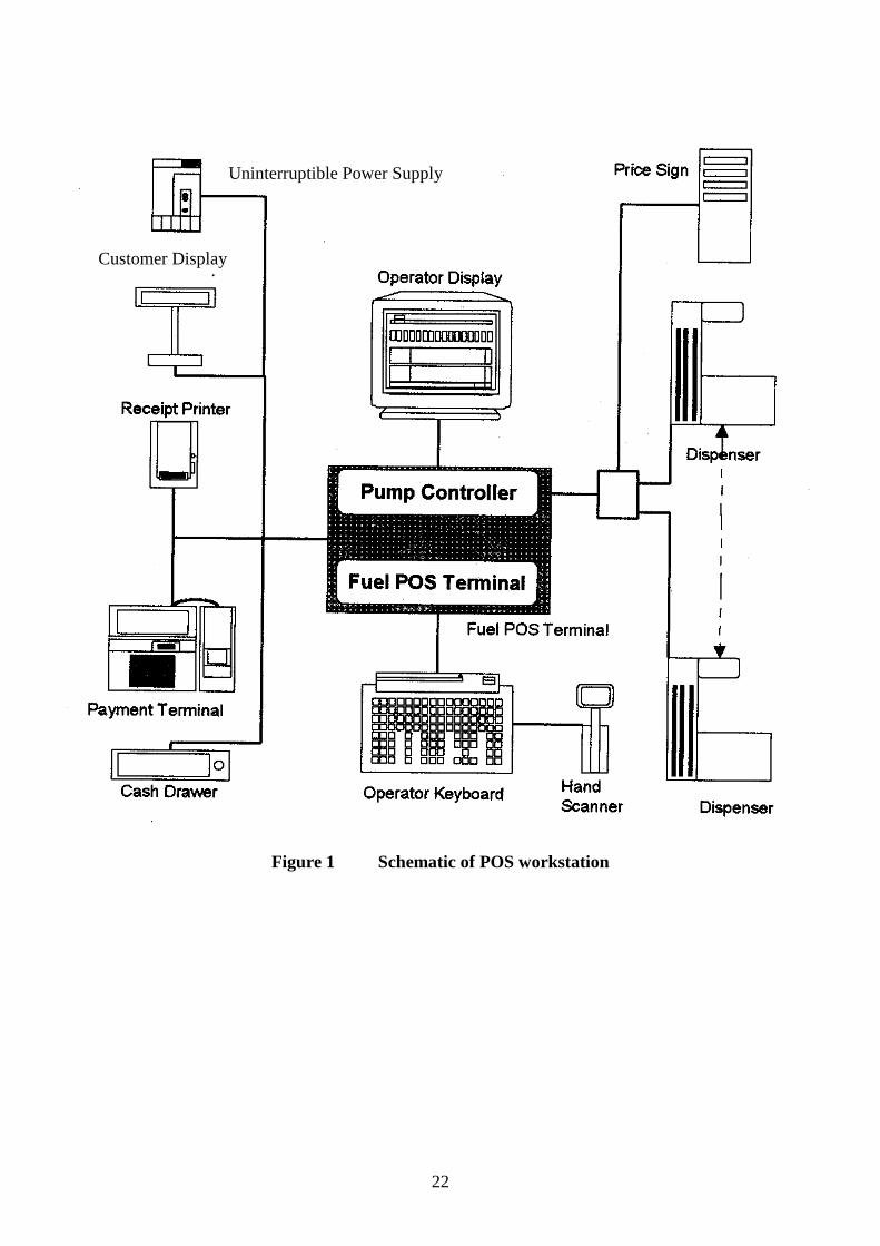
POS (Figure 1)
Standard equipment: (a) Uninterruptible power supply
(b) Fuel POS terminal
(c) Operator display
(d) Operator keyboard
(e) Customer display
(f) Receipt printer
Additional equipment: (g) Payment terminal
(h) Cash drawer
(i) Hand scanner
(j) Pump controller
CIS (Figure 2)
Standard equipment: (a) Uninterruptible power supply
(b) Central information system
Additional equipment: (c) Report printer
(d) Local back office computer
(e) Tank level system
(f) Pump controller
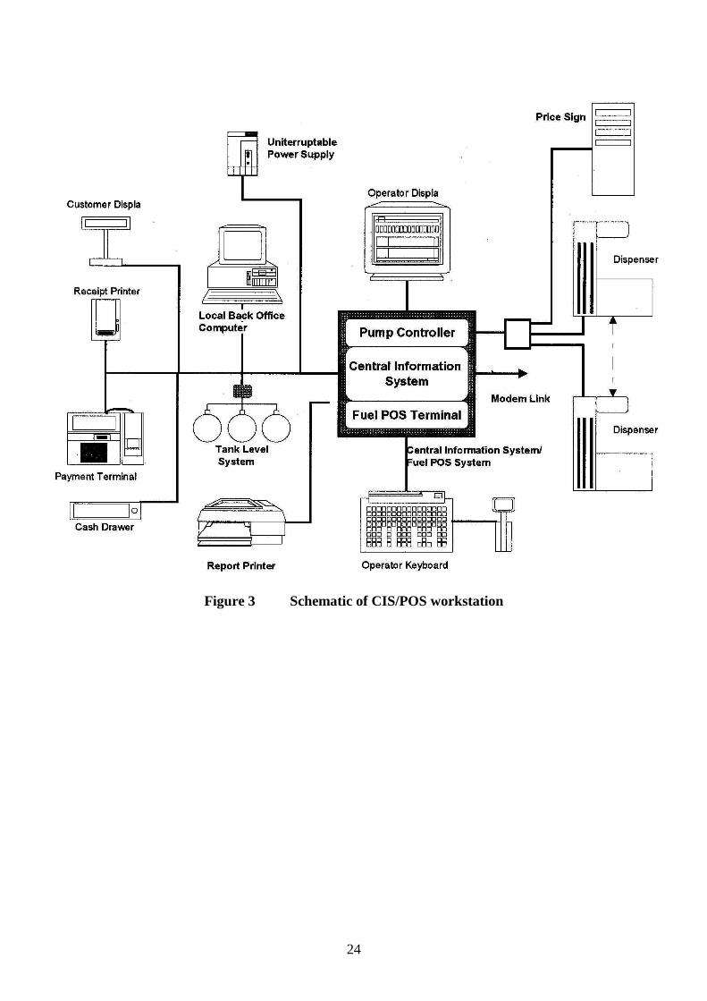
CIS/POS (Figure 3)
Standard equipment: (a) Uninterruptible power supply
(b) Central information system/fuel POS terminal
(c) Operator display
(d) Operator keyboard
(e) Customer display
(f) Receipt printer
Additional equipment: (g) Report printer
(h) Payment terminal
(i) Hand scanner
(j) Cash drawer
(k) Tank level system
(l) Local back office computer
(m) Pump controller
4
Omega-FuelPOS Systems can be assembled, from these workstations, into two separate types
of system:
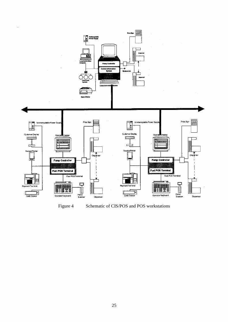
CIS System (Figure 4)
This comprises a CIS connected to one or more POS’s. The workstations are connected via a
LAN, with one or more communicating with the forecourt equipment.
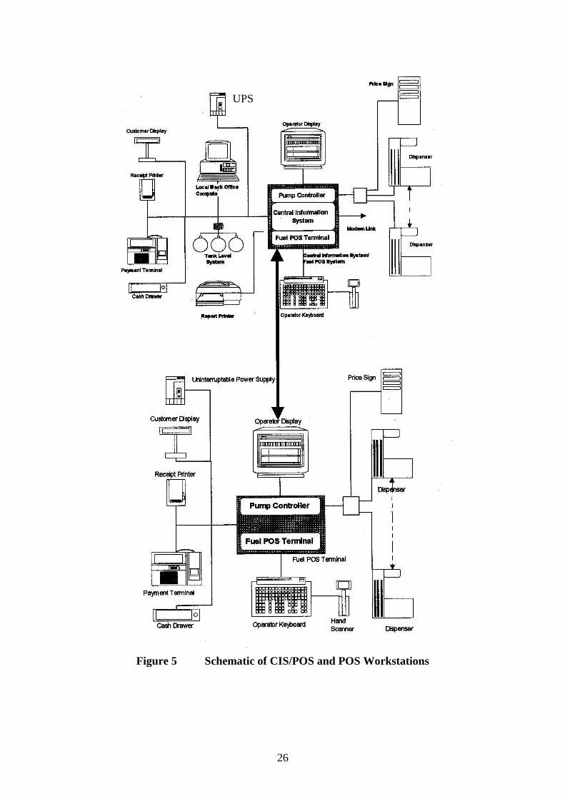
CIS/POS System (Figure 5)
This system comprises a CIS/POS, optionally, connected to a single POS. The workstations
are connected via a LAN, with one or more communicating with the forecourt equipment.
Approved software for the Fuel POS Terminal
Fuel POS: 02PCC11.XX DD-MM-YY
Fuel POS: 02PCC12.XX DD-MM-YY
Approved software for the Central Information System:
Central Inf. System: 02CIS11.XX DD-MM-YY
Central Inf. System: 02CIS12.XX DD-MM-YY
Approved software for the Pump Controller:
PCU POS N: UK LON 1.7.X YYMMDD
Where: XX is the minor revision number
DD-MM-YY is the day, month and year of the revision
YYMMDD is the year, month and day of the revision
N is the number of the workstation
Note: (a) The menu will show a PCU POS entry for each workstation, which has a
pump controller. The number of entries, therefore will vary between none and the number of
workstations. There can also be different software in each pump controller.
(b) There will be only one software entry for both the POS and CIS.
(c) The software is routinely revised and updated in the field and subsequently
reissued with a new version number.
5
2 CONSTRUCTION
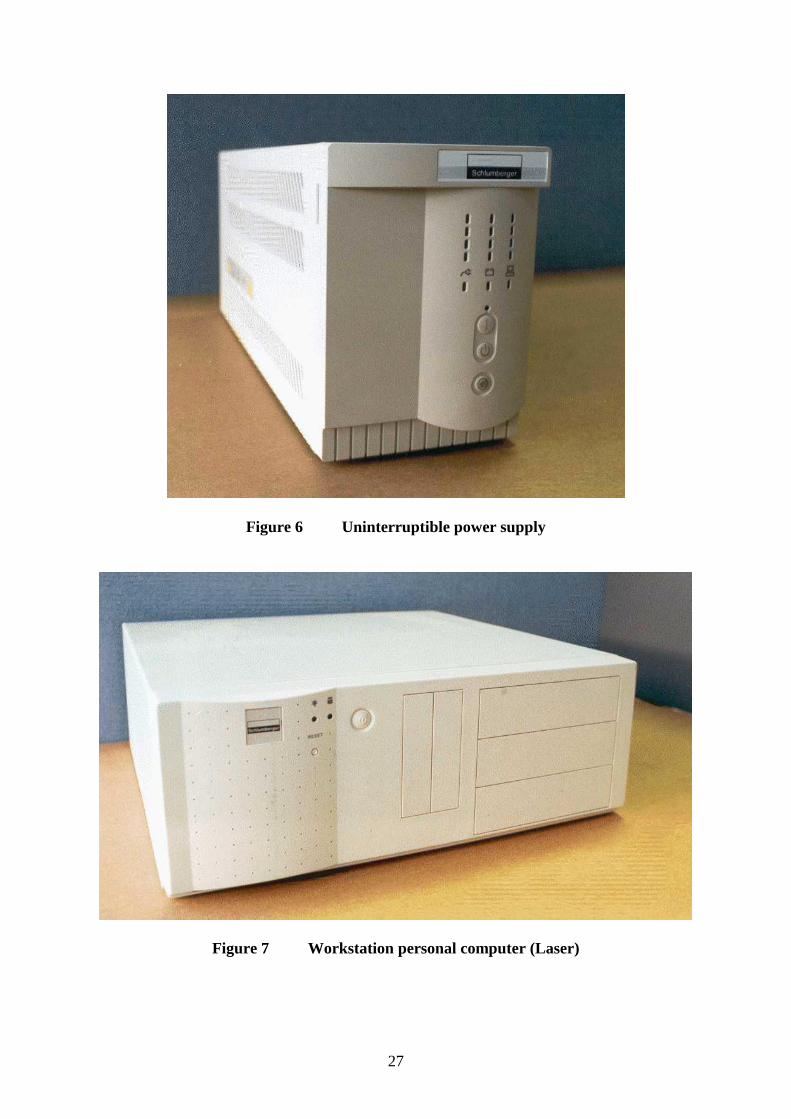
2.1 Uninterruptible power supply (Figure 6)
All workstations and the standard equipment are connected to these units, one unit per
workstation, to provide power in the absence of mains input. The units are manufactured by
`Fiskars' and are of the `PowerRite' range.
2.2 Central information system/fuel POS terminal (Figure 7)
The unit is an Intel Pentium II ATX personal computer with ‘application specific’ modules,
namely forecourt control board (COB), and forecourt interface board (FIB), and is
programmed by Tokheim for all forecourt functions. The computer monitors and controls all
forecourt operations and kiosk transactions and has an optional capability of site
management. The workstation personal computer contains the following major components.
2.2.1 Power supply
The power supply provides DC power for the internal logic boards and some of the attached
peripherals.
2.2.2 Motherboard
Pentium II motherboard containing Intel Pentium II processor and memory components.
2.2.3 Local area network (LAN)
The computer contains an Ethernet card for connecting other workstations. The LAN uses
Thin Net (10-base-2) coaxial cable connections via BNC connectors.
2.2.4 Forecourt control board (COB)
If the workstation has a pump controller then a Tokheim COB, model COB-KSS COB-
KFF, controls forecourt activity.
2.2.5 Forecourt interface board (FIB)
The workstation pump controller is FIB-L (IFSF), which interfaces between Quantium
ATM and the Omega-FuelP0S controller.
2.2.6 Disk drives
The computer contains a hard drive. Optionally, a pair of hard drives may be fitted for
mirrored operation.
2.2.7 Serial communications board
The computer contains a serial communications board, manufactured by `Digi International'
and provides serial interfaces to certain external peripheral components up to a maximum of
eight.

6
2.2.8 Video board
The computer contains a video board installed in the AGP slot.
2.2.9 Modem card
The CIS and CIS/POS workstations contain a modem card to allow remote diagnostics and
credit card polling.
2.3 Operator display (Figure 8)
The operator display is a cathode ray tube colour monitor, which provides the operator with
forecourt status information, transaction data for each fuel dispenser, gives a visual display of
all the operator's commands and instructions and all retail transactions. A diagram showing
the layout of the operator display monitor is shown in Figure 9.
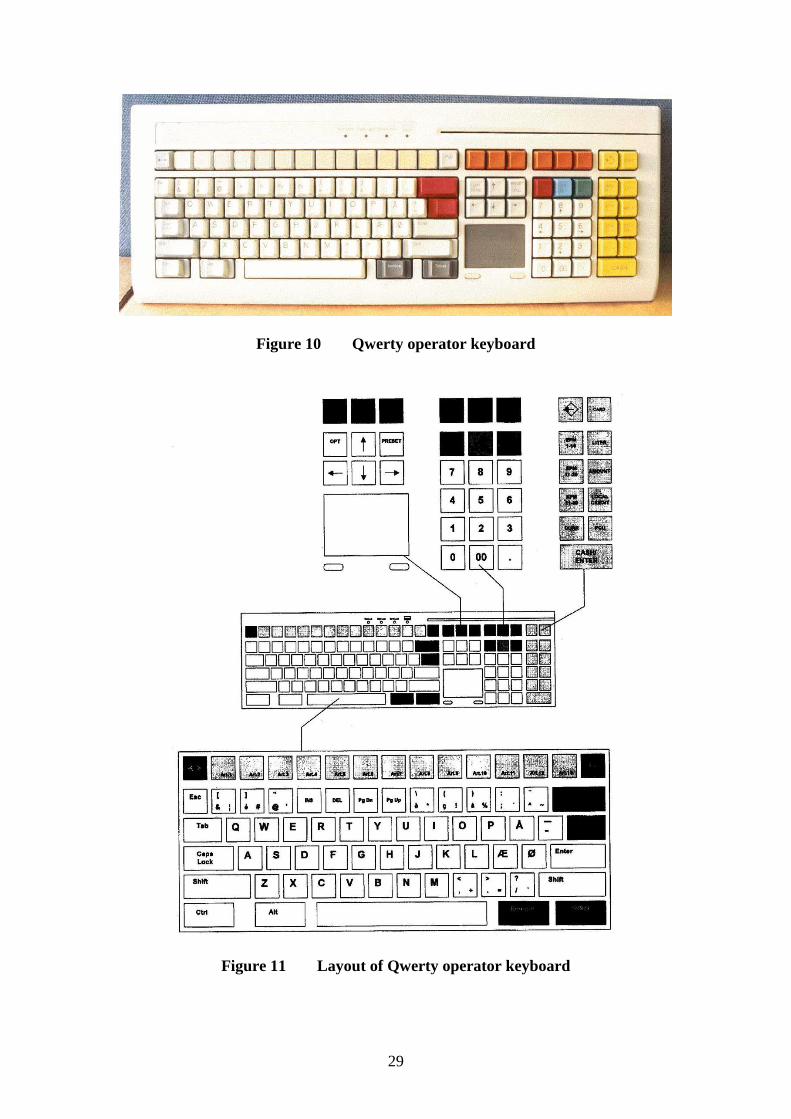
2.4 Qwerty operator keyboard (Figure 10)
The operator keyboard is manufactured by Preh, and is designated `Preh Commander PC-
POS'. A diagram showing the layout of the keyboard is shown in Figure 11. On the top left
of the keyboard is a row of keys used to directly access articles. Below this is a standard
Qwerty layout for alpha data entry. To the top right are transaction control keys. Below this
is a trackpad, numeric keypad and payment keys.
There are three keys above the numeric keypad, marked `Stop', `Display', and `Release'.
These keys are used in combination with the numeric keypad to control the forecourt filling
positions.
The keyboard has a card reader built into the top right hand corner.
2.5 Customer display (Figure 12)
The customer display is manufactured by Epson and is designated DM-202 and consists of
two rows of green fluorescent 12 mm high digits for displaying the identity of filling position,
volume dispensed, sale amount and whether the transaction is a current or a stored sale. A
diagram showing the layout of the customer display is shown in Figure 13. The display
measures approximately 260 mm x 780 mm and is pedestal mounted to a height of 400 mm.
Power is supplied by an Epson 24 V power supply module, which is connected to the UPS.
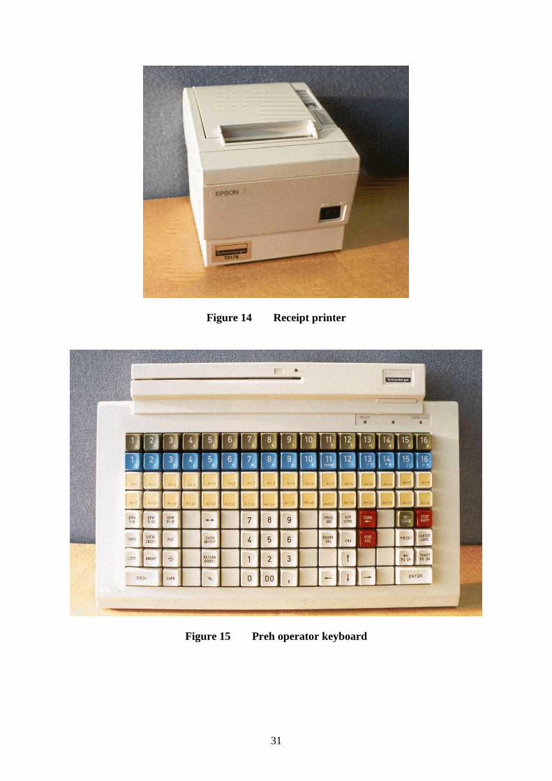
2.6 Receipt printer (Figure 14)
The receipt printer is manufactured by Epson and is designated TM-88 and consists of a
single thermal print roll with tear-off strip for credit card vouchers and customer receipts.
Power is supplied by an Epson 24 V power supply module, which is connected to the UPS.

7
3 OPERATION
3.1 Dispenser monitoring (Figure 9)
The dispensers' status is displayed on the operator display. The screen is divided into six
windows, namely: operator message window, FIP status window, fuel sale display window,
transaction builder window, operator entry window, and sub-total window.
3.1.1 Operator message window
This window is used to inform the operator of status and error conditions. The status and
error messages are visible for a short time with an audible signal before the window reverts to
the standard title display.
3.1.2 FIP status window
The window will permanently display between 1 and 28 rectangles, the lower half of each
rectangle displaying a number which represents the forecourt filling position (FIP). The FIP
rectangles show the current status of each dispenser on the forecourt as follows:
BLANK rectangle (IDLE) FIP not in use, not authorised
RED rectangle (REQUEST) Nozzle removed, awaiting authorisation
HALF GREEN rectangle (AUTHORISED) FIP authorised
GREEN rectangle (FILLING) Dispensing fuel
BLANK rectangle (IDLE) with bar beneath Nozzle stowed, transaction awaiting payment.
Normally the rectangle outline is a solid line. If the rectangle outline consists of a broken
line, then this indicates that the system has lost communication with the pump.
3.1.3 Fuel sale display window
When the operator selects a FIP using the 'display' key, the details of unpaid fuel sales
associated with that dispenser are displayed in this window. In the case that two fuel sales
are unpaid the operator can switch between the sales using the cursor keys. When the correct
sale is selected it can be transferred to the transaction builder window for payment.
3.1.4 Transaction builder window
This window displays all the items in a transaction, fuel and shop sales, listing each item with
a short descriptive text, quantity, unit price.
3.1.5 Operator entry window
This window displays the operator's typed command such as a bar code item number as an
alternative to using the bar code scanner. A typed entry is transferred to the transaction
builder window using the enter key.

8
3.1.6 Subtotal window
This window displays the running total of items listed in the transaction builder window.
3.2 Authorising the dispensers
When a purchaser removes the nozzle on a dispenser the appropriate FIP rectangle changes
form blank to red and a short audible beep sounds.
The operator can then authorise the dispenser by entering the FIP number on the numeric pad
then pressing the 'Release' key. The FIP rectangle will change from red to half green.
When the purchaser starts dispensing fuel, the FIP rectangle changes from half green to
green.
The pump can be stopped at any time by entering the FIP number and pressing the 'Stop' key.
All pumps can be stopped at any time by pressing the `00' (double zero) key, and pressing the
`Stop' key.
3.3 Outstanding transactions
When the purchaser returns the nozzle, the appropriate FIP rectangle changes from green to
blank, and a transaction bar appears under the rectangle. This indicates that the transaction is
outstanding and awaiting payment.
If a second purchaser removes the nozzle the FIP rectangle changes from blank with a
transaction bar to red with a transaction bar and the sequence then continues as in Section 3.2
for the second purchaser. When the second purchaser returns the nozzle a second transaction
bar will be displayed below the first bar.
It is not possible to authorise a third purchaser until one of the outstanding transactions has
been paid for.
3.4 Viewing a transaction
To view a transaction, the operator enters the appropriate FIP number using the numeric
keypad and presses the `Display' key. Any outstanding transactions on that FIP are displayed
in the fuel display window. If there is only one transaction, then this is highlighted. If there
are two transactions, the first transaction is highlighted, but the operator can highlight either
transaction using the cursor keys. The highlighted transaction is displayed to the purchaser
on the customer display.
3.5 Agreeing at transaction
If the purchaser agrees with the highlighted fuel transaction details then the sale can be
transferred to the transaction builder window by pressing the `Enter' key. At this point the
transaction bar becomes a transparent rectangle, indicating that the transaction has been
claimed by a POS. Further items may be added to the sale in the transaction builder window
before completing the transaction with a payment.

9
If the purchaser does not intend to add further items and is paying cash, then the fuel
transaction may be 'cashed out' directly from the fuel display window by pressing the `Cash'
key.
3.6 Voiding a transaction
The customer has the opportunity to agree the transaction details whilst they are highlighted
in the fuel sale display window. However, if the wrong sale is transferred to the transaction
builder window, then voiding the fuel sale prior to payment, using the `Corr' or `Void' keys,
will return the transaction to the FIP display. The transaction bar will become solid and the
sale will again be available to all POSs. Check if this is possible only if another transaction
has not been added.
3.7 Adding a second fuel transaction
A second fuel transaction may be added to the receipt by following the same procedure as in
Sections 3.4 and 3.5.
3.8 Adding dry goods
Any shop item may be added to the transaction (receipt) using one of the following methods.
3.8.1 Using a direct article access key
Pressing one of the direct article access keys will add the associated article to the transaction
builder window.
3.8.2 Price look-up number (PLU)
Entering a code number associated with the article and pressing the `PLU' key will add the
associated article to the transaction builder window.
3.8.3 Barcode scanner
The barcode product label on the product may be scanned or manually entered to add the
associated article to the transaction builder window.
3.9 Method of payment
3.9.1 Cash sales
When the purchaser requests to pay by cash and presents the exact money to settle, the
operator presses the 'Cash' key and the cash drawer opens. Closing the cash drawer
completes the transaction and the customer display reverts to the welcome message.
If the purchaser presents a higher amount than that required to settle, the operator keys in the
amount on the numeric keypad then presses the 'Cash' key. The customer display then
displays the change to be returned and the cash drawer opens. Closing the cash drawer
completes the transaction and the customer display reverts to the welcome message.

10
3.9.2 Card sales
When the purchaser requests to pay by card the operator accepts the customer's card, presses
the `Card' key, and passes the card through the card reader.
If card handling is performed by an external terminal, the details are passed to the terminal
and the operator display shows `transaction sent to terminal'. The transaction is completed on
the terminal as required and the result is returned to the POS. If the card was rejected, then
the POS will prompt for an alternative payment method. If the card was accepted then the
transaction is completed and a receipt can be printed by pressing the `Ticket' key.
If card handling is performed directly by the POS, then the POS will prompt the operator for
any additional information required. A ticket will be printed for the customer to sign and the
operator is prompted `signature OK?'. If the signature is rejected, then the POS will prompt
for an alternative payment method. If the signature is accepted, then the transaction is
completed and a receipt is printed.
3.9.3 Cheque/other sales
Various other methods of payment, such as cheque, manual card voucher, local account,
foreign currency, can be registered by pressing one of the payment keys on the right hand
side of the operator keyboard. The transaction is completed and a receipt can be printed by
pressing the `Ticket' key.
3.10 Interlocks and security features
3.10.1 Third purchaser
A third transaction cannot be authorised for a particular filling position until at least one of
the preceding transactions has been completed.
3.10.2 Manual fuel sale
It is not possible to enter a manual fuel sale.
3.10.3 Duplicate receipts
It is not possible to duplicate the same fuel transaction on a receipt. If additional receipts are
produced they are clearly marked `COPY' or ‘DUPLICATE’
3.10.4 Power failure
In the event of a mains power failure, the system operates on back-up power for at least 15
minutes during which time transactions can be paid for.
If there are transactions unpaid after this time, the system will automatically 'cash-out' the
transactions and produce a printed record of the transaction details on the receipt printer of
the first POS before shutting down.

11
3.10.5 Customer display
The customer display has the capability of displaying either of the two transactions held as
FIP transaction bars (stored and current sales), for the purchaser agreement and payment,
using a manual method.
3.10.6 Multiple POS transaction selection
Where there are two or more POS terminals a transaction cannot be `claimed' by more than
one POS terminal at the same time. However, a current transaction may be claimed by one
POS and the stored transaction claimed by another, at the same time.
4 AUTHORISED ALTERNATIVES
4.1 Barcode scanner
Any CE marked barcode scanner may be connected to the operator keyboard or between the
operator keyboard and the workstation.
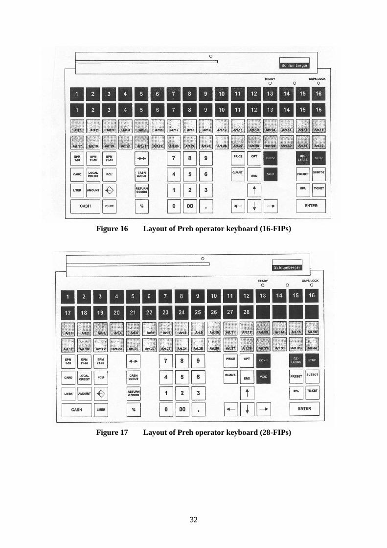
4.2 Preh operator keyboard
An alternative keyboard manufactured by Preh, designated Commander M128X (Figure 15).
A layout of the 16 FIP version of this keyboard is shown in Figure 16. Across the top of the
keyboard is a row of 16 dispenser release keys, with a further 16 dispenser claim keys
directly underneath. The 16 release and claim keys relate to the numbered rectangles 1 to 16
in the pump control window of the operator display monitor. Pressing the relevant release or
claim key is equivalent to entering the FIP number and pressing the `Release' or `Display' key
of the standard keyboard.
The Preh keyboard has a socket to the rear for connection of a barcode scanner, and a socket
to the right hand side for connection of a CE marked Qwerty keyboard for maintenance
purposes.
The Preh keyboard may be fitted with a CE marked card reader which fixes to the uppermost
edge.
The 16 FIP version may be replaced with a 28 FIP version, a layout is shown in Figure 17. In
this case the top two rows contain the dispenser claim keys.
4.3 Management printer
Any CE marked printer may be connected to a workstation for non-trade and management
purposes.
4.4 Modem
A BABT approved and CE marked modem may be fitted in a workstation. Also any BABT
approved and CE marked modem may be connected, using serial communications, to a port
on the serial communications board of the workstation.

12
4.5 Operator display (LCD)
A CE marked LCD flatscreen monitor may be used instead of the CRT monitor. The layout
and functionality is the same as described for the CRT monitor.
4.6 Tank level gauge
Any CE marked tank level gauge detecting system may be connected, using serial
communications, to a port on the serial communications board of a workstation.
4.7 Price sign
The pole sign fuel price display may be connected, using serial communications, to a port on
the Forecourt Interface Board (FIB) of a workstation.
4.8 Local back office computer
A CE marked personal computer may be connected, using serial communications, to a port
on the serial communications board of the a workstation, or by Ethernet connection to the
kiosk LAN, for external site management purposes.
4.9 Car wash
A car wash controller may be connected, using serial communications, to a port on the serial
communications board of a workstation.
4.10 Shop version POS
One or more the POS terminals connected to the kiosk LAN may be configured in shop
mode. In this case the shop POS does not have any pump control functions and is used for
sales of shop articles and access to management functions only.
On a standard Qwerty operator keyboard, the Stop, Release, and Display keys are inactive.
On a Preh keyboard, the 16 release and 16 claim keys are replaced by an additional 32 direct
article access keys.
4.11 LPG
Any CE marked LPG dispenser may be connected via a connection to the forecourt interface
board (FIB).
4.12 Payment terminal
Any CE marked indoor payment terminal may be connected, using serial communications, to
a port on the serial communications board of a workstation.
4.13 Cash drawer
Any CE marked cash drawer may be connected, using serial communications, to a port on
the serial communications board of a workstation.

13
4.14 Loyalty card terminal
Any CE marked loyalty card terminal may be connected, using serial communications, to a
port on the serial communications board of a workstation.
4.15 Microsoft NT 2000 operating system
The software and data within FuelPOS is protected against ‘Intentional Changes with
Common Software Tools’ by restricting access to the Operating System. Access is only
possible by using a Security Card and PIN number. These cards and PIN numbers are only
issued to Tokheim Authorised personnel.
The FuelPOS is not installed with a Floppy Disk drive and is configured to 'boot' off the
installed hard-drive only. On power-up, the FuelPOS will also lock the CD-ROM drive and
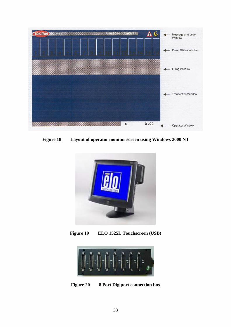
render it inoperable. It can only be unlocked by access at the Operating System level. With
the up-dated software the layout of the operator display has been changed to that shown in
Figure 18. The software is now designated as: -
Fuel POS: EUR ZZ.X DD-MM-YY
Central Inf. System: EUR ZZ.X DD-MM-YY
PCU POS N: UK LON Z.Z.X YYMMDD
PCU POS N: UK M6 Z.Z.X YYMMDD
PCU POS N: UK GB2W Z.Z.X YYMMDD
PCU POS N: EUR ZZXX GB ALL YYMMDD
Where: Z/ZZ is the major revision number
X is the minor revision number
DD-MM-YY is the day, month and year of the revision
YYMMDD is the year, month and day of the revision
N is the number of the workstation
GB ALL country specific to all versions
Note: The software is routinely revised and updated in the field and subsequently reissued
with a new version number.
4.15.1 Microsoft Windows XP
The system may use XP Pro as an alternative operating system.
4.16 Extended interface capability
This enhanced capability is implemented by use of software programming and by the use of a
range of plug-in modules and interface assemblies. These systems and devices may be
optionally installed and are as detailed below.
4.16.1 ELO Touchscreen
The VDU described in the certificate may optionally be replaced with an ELO USB touch
screen with integrated card swipe, or with any suitable CE marked touchscreen. Figure 19
shows the ELO VDU.
14
4.16.2 Digiboard Card and Connection Box
The Digiboard comms. port expansion unit comprises a full size PC card with a multi
connector to an external box with 8, 25 pin ‘D’ connectors as shown in Figure 20.
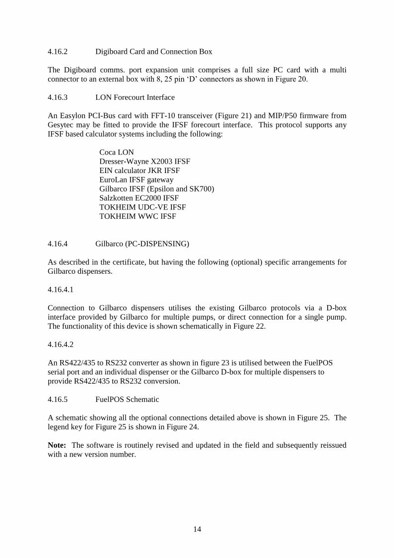
4.16.3 LON Forecourt Interface
An Easylon PCI-Bus card with FFT-10 transceiver (Figure 21) and MIP/P50 firmware from
Gesytec may be fitted to provide the IFSF forecourt interface. This protocol supports any
IFSF based calculator systems including the following:
Coca LON
Dresser-Wayne X2003 IFSF
EIN calculator JKR IFSF
EuroLan IFSF gateway
Gilbarco IFSF (Epsilon and SK700)
Salzkotten EC2000 IFSF
TOKHEIM UDC-VE IFSF
TOKHEIM WWC IFSF
4.16.4 Gilbarco (PC-DISPENSING)
As described in the certificate, but having the following (optional) specific arrangements for
Gilbarco dispensers.
4.16.4.1
Connection to Gilbarco dispensers utilises the existing Gilbarco protocols via a D-box
interface provided by Gilbarco for multiple pumps, or direct connection for a single pump.
The functionality of this device is shown schematically in Figure 22.
4.16.4.2
An RS422/435 to RS232 converter as shown in figure 23 is utilised between the FuelPOS
serial port and an individual dispenser or the Gilbarco D-box for multiple dispensers to
provide RS422/435 to RS232 conversion.
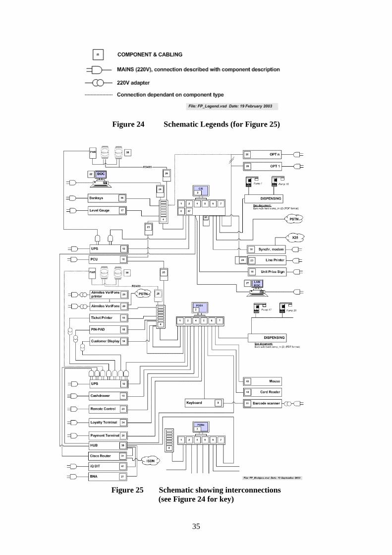
4.16.5 FuelPOS Schematic
A schematic showing all the optional connections detailed above is shown in Figure 25. The
legend key for Figure 25 is shown in Figure 24.
Note: The software is routinely revised and updated in the field and subsequently reissued
with a new version number.

15
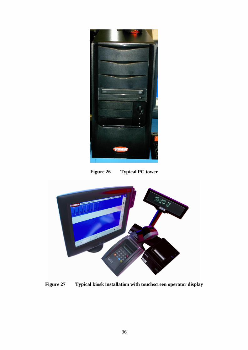
4.17 Alternative tower PC
As described in the certificate but having the PC workstation replaced with a PC tower
format as shown in Figure 26. The tower may, optionally be fitted with a DVD drive.
The legally relevant hardware is identified in the table below:
Module Manufacturer Model Number Tokheim Part Number
PC Tower Tokheim Ltd
Pentium 4 and
Pentium 4 M
Celeron PC
IPOX IP-4GV163 9210013964
Pentium 4 and
Celeron
IPOX IP-4GV183 9210014084
Uninterruptible
power supply
Any CE marked UPS of
sufficient capacity to
maintain operation of the
POS in excess of 15 minutes
during power failure.
IP-4GV163 board is fitted with ISA support and operates with the COB pump interface
connections.
IP-4GV183 board is fitted with PCI support and operates with PCI LON (IFSF) PC
dispensing boards.
Figure 27 shows a typical kiosk installation with touch screen operator display
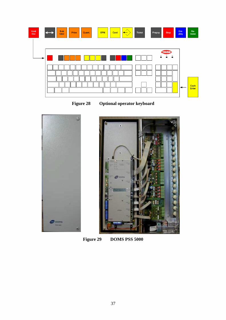
An alternative conventional QWERTY operator keyboard may be supplied fitted with pump
control keys as shown in Figure 28.
Forecourt operations and kiosk transactions may be controlled by the operator on the
touchscreen LCD monitor, keyboard or a combination of both.
4.17.1 Alternative hardware - Dell 390 PC
4.17.2 Alternative hardware - Mitac 'Mini FuelPOS-PC'
4.18 Alternative Keyboard
Any CE approved standard keyboard may be used where site operation is run by touchscreen
only.
4.19 Alternative System Configuration using DOMS PSS5000 site controller
4.19.1 Description
The DOMS Petro Site System (PSS) 5000 is a direct replacement for the PSS 2000. The PSS
5000 reflects recent changes in technology; the Central Processing Board (CPB) includes a
WEB Server.

16
Support previously provided by the Main Protocol Converter (MPC) and Tiny Protocol
Converter (TPC) has been integrated into the CPB. The type of Hardware Interface Module
(HIM) used to interface to the various supported Pump and Tank manufacturers are the same
as those previously used in the PSS 2000.
4.19.2 Construction
The DOMS PSS5000 forecourt controller comprises a metal rectangular box (Figure 29)
housing the following main components.
A power supply
A Central Processing Board (CPU) with 8 serial ports (CPB508).
This has an LCD 16x2 character alphanumerical display and a keyboard comprising 5
keys for navigating the menu options, an adjacent legend describes the key functions
as shown in Figure 16.
Hardware interface modules.
Dispensers are connected to the CPU board via an appropriate hardware interface
module compatible with the communication protocol of the dispenser.
4.19.2.1 Software
The DOMS PSS5000 has a legal authority module (LAM) for the UK containing specific
parameter values and functions. The LAM version number is 498-06-100 and the checksum
number is 0D6C. These can be viewed by selecting the appropriate menu heading using the
operator keys on the CPU. The LAM version number and checksum are accessed as follows.
When the PSS is powered on, the first line displays the application software version and the
current time. The second line displays the W&M Service menu. Pressing the Down Arrow
once, displays the W & M menu which comprises 7 sub-menus, W.1 to W.7. Press the right
button once to obtain W.1 – LAM INFO and press again to display Version and Checksum
information.
4.20 Alternative System Configuration using DOMS PSS2000 site controller
4.20.1 Description
The DOMS PSS2000 is housed in a metal rectangular box. It controls the interaction between
the POSs and the dispensers (Figure 30).
4.20.2 Construction
Internally, there are three main sub-assemblies: the power supply unit, the processor unit, and
the interface boards. Interconnection between these units is via ribbon cables. There may be a
number of interface boards depending on the number of dispensers connected to the system
and whether a tank gauge is connected to it or not. The connections to the KCU, tank gauge
and dispensers are made on the appropriate interface boards. The processor unit is a
PROM/EPROM based unit and handles the control signal from the dispensers to the KCU.
The sub-assemblies and interface boards are all mounted onto a DIN rail inside the housing.
A mains supply is made to the unit via a fused assembly within the housing. The DOMS
PSS2000 is powered through the main pump Emergency Stop button.

17
4.21 Alternative Hardware Configuration - In-Tech Solutions IPOS Point of Sale
System
4.21.1 Description
Upon completion of the delivery, the operator selects the fuel transaction via the In-Tech
IPOS or Tokheim FuelPOS. When selected using the In-Tech IPOS, the FuelPOS transmits
the real time transactions to the In-Tech IPOS. The Tokheim FuelPOS has full control of the
pumps, and it is only once the sale is been completed and authorised that the transaction is
transferred to the In-Tech IPOS. If the transaction is cashed on the Tokeim FuelPOS it
cannot be transferred to the In-Tech IPOS.
After the transaction is transferred to the In-Tech IPOS the fuel payment, along with any
other items purchased, is completed on the In-Tech POS.
4.21.2 In-Tech IPOS Hardware
Till configuration #1
PC base unit DigiPos Retail Active 8000
Operator display DigiPos touch screen
Receipt printer Epson TM-T88
Barcode scanner Metrologic Quantum
Customer display 2 line
Till configuration #2
PC base unit Hewlett Packard RP5700
Operator display MultiQ touch screen
Receipt printer Star TSP100
Barcode scanner Metrologic Quantum
Customer display 2 line
These configurations may include other ancillary devices such as a cash drawer, Avery
FX110/120 scales and Verifone, Dione Secura or Ingenico iPP350 PIN Pads.
4.21.3 In-Tech IPOS Software
The software had been segregated so that the fuel aspects of the program are contained within
a standalone component (i.e. FuelPos.DLL), and the operational and management functions
have been written into both IPOS.EXE and SETUP.EXE. The operational and management
software versions can change, but have no effect on the standalone fuel component.
4.21.3.1 The standalone fuel component is protected from user tampering by use of
CRC checking which is activated at every power-on of the system or may be re-checked by
following this procedure:
At the sign-on screen enter the cashier code of 8145 and press the ENTER button.
Enter the same number (8145) as the cashier password and press the ENTER button.
On the main operating screen, press the management menu button. This button is
usually labelled “Mgr Menu” or “Manager Menu”.
18
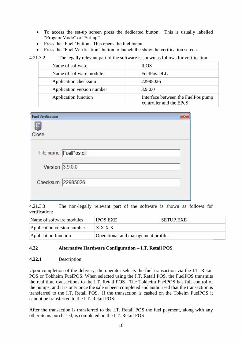
To access the set-up screen press the dedicated button. This is usually labelled
“Progam Mode” or “Set-up”.
Press the “Fuel” button. This opens the fuel menu.
Press the “Fuel Verification” button to launch the show the verification screen.
4.21.3.2 The legally relevant part of the software is shown as follows for verification:
Name of software IPOS
Name of software module FuelPos.DLL
Application checksum 22985026
Application version number 3.9.0.0
Application function Interface between the FuelPos pump
controller and the EPoS
4.21.3.3 The non-legally relevant part of the software is shown as follows for
verification:
Name of software modules IPOS.EXE SETUP.EXE
Application version number X.X.X.X
Application function Operational and management profiles
4.22 Alternative Hardware Configuration – I.T. Retail POS
4.22.1 Description
Upon completion of the delivery, the operator selects the fuel transaction via the I.T. Retail
POS or Tokheim FuelPOS. When selected using the I.T. Retail POS, the FuelPOS transmits
the real time transactions to the I.T. Retail POS. The Tokheim FuelPOS has full control of
the pumps, and it is only once the sale is been completed and authorised that the transaction is
transferred to the I.T. Retail POS. If the transaction is cashed on the Tokeim FuelPOS it
cannot be transferred to the I.T. Retail POS.
After the transaction is transferred to the I.T. Retail POS the fuel payment, along with any
other items purchased, is completed on the I.T. Retail POS
19
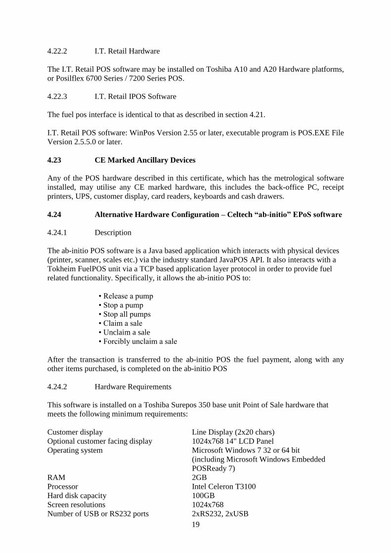
4.22.2 I.T. Retail Hardware
The I.T. Retail POS software may be installed on Toshiba A10 and A20 Hardware platforms,
or Posilflex 6700 Series / 7200 Series POS.
4.22.3 I.T. Retail IPOS Software
The fuel pos interface is identical to that as described in section 4.21.
I.T. Retail POS software: WinPos Version 2.55 or later, executable program is POS.EXE File
Version 2.5.5.0 or later.
4.23 CE Marked Ancillary Devices
Any of the POS hardware described in this certificate, which has the metrological software
installed, may utilise any CE marked hardware, this includes the back-office PC, receipt
printers, UPS, customer display, card readers, keyboards and cash drawers.
4.24 Alternative Hardware Configuration – Celtech “ab-initio” EPoS software
4.24.1 Description
The ab-initio POS software is a Java based application which interacts with physical devices
(printer, scanner, scales etc.) via the industry standard JavaPOS API. It also interacts with a
Tokheim FuelPOS unit via a TCP based application layer protocol in order to provide fuel
related functionality. Specifically, it allows the ab-initio POS to:
• Release a pump
• Stop a pump
• Stop all pumps
• Claim a sale
• Unclaim a sale
• Forcibly unclaim a sale
After the transaction is transferred to the ab-initio POS the fuel payment, along with any
other items purchased, is completed on the ab-initio POS
4.24.2 Hardware Requirements
This software is installed on a Toshiba Surepos 350 base unit Point of Sale hardware that
meets the following minimum requirements:
Customer display
Line Display (2x20 chars)
Optional customer facing display 1024x768 14" LCD Panel
Operating system Microsoft Windows 7 32 or 64 bit
(including Microsoft Windows Embedded
POSReady 7)
RAM 2GB
Processor Intel Celeron T3100
Hard disk capacity 100GB
Screen resolutions 1024x768
Number of USB or RS232 ports 2xRS232, 2xUSB
20
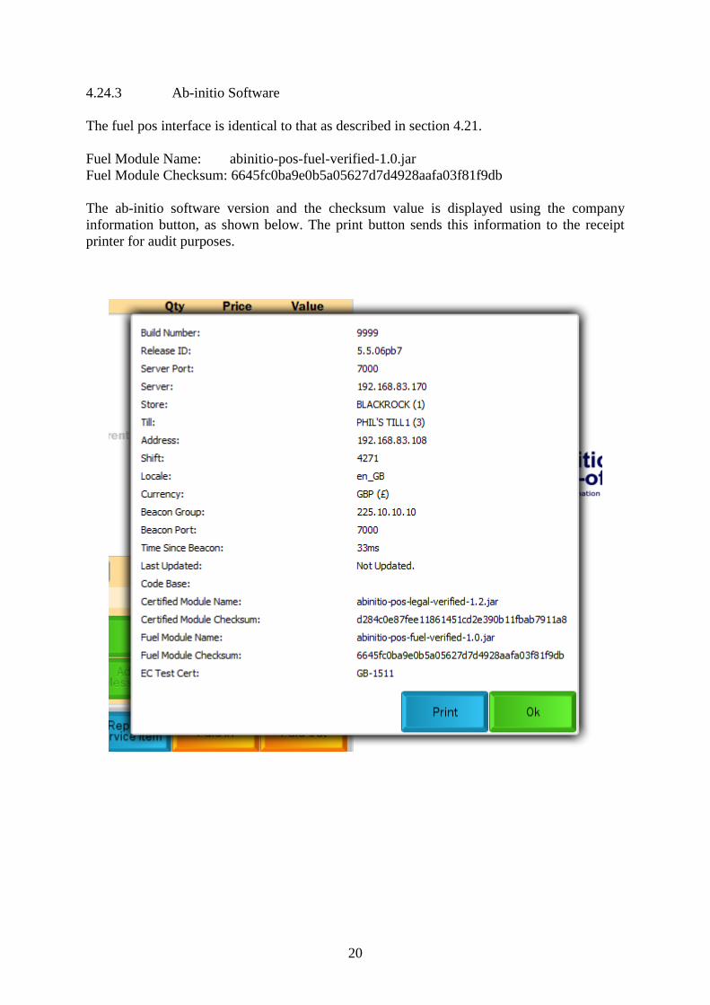
4.24.3 Ab-initio Software
The fuel pos interface is identical to that as described in section 4.21.
Fuel Module Name: abinitio-pos-fuel-verified-1.0.jar
Fuel Module Checksum: 6645fc0ba9e0b5a05627d7d4928aafa03f81f9db
The ab-initio software version and the checksum value is displayed using the company
information button, as shown below. The print button sends this information to the receipt
printer for audit purposes.

21
5 RECOMMENDED TESTS
The following tests may be carried out in addition to those specified in the Regulations to
determine conformity to the approval pattern.
5.1 Software verification
Check that correct software versions, as detailed in Section 1, are installed in the
workstations. These can be accessed from the CIS menu, from any POS, and going to the
sub-menu `SW version' from the menu `System'.
Note: The equipment supplier operates a system whereby software updates are implemented
on a regular basis. These changes will not affect the metrological programming, but will
cause the software references DD MM YY to change depending on the date of amendment.
Inspectors requiring confirmation of current software status should contact the equipment
supplier, or NMO.
6 CERTIFICATE HISTORY
ISSUE NO. DATE DESCRIPTION
Series S011 11 October 2007 Certificate first issued as a supplement.
Series S011 Revision 1 25 March 2009 14.15 Alternative operating system: Microsoft
Windows NT
VScom 8 port serial
Series S011 Revision 2 14 March 2012 Front page Fuel dispenser 1958 added
4.15.1 Alternative operating system: Microsoft
Windows XP
Alternative hardware:
4.17.1 Dell 390
4.17.2 Mitac 'Mini FuelPOS-PC'
4.19 and 4.20 Doms site controllers added
Series S011 Revision 3 30 January 2013 Section 4.21 Alternative hardware
configuration In-Tech IPOS added
Series S011 Revision 4 08 May 2014 Section 4.22 Alternative hardware
configuration I.T. Retail Pos added
Section 4.23 CE marked ancillary devices
added
Series S011 Revision 5 30 September 2014 Section: 4.15: PCU POS N, EUR version
added, key updated
5.1 (Note) reference to NWML
changed to NMO
Series S011 Revision 6 9 February 2014 Section: 4.24 Alternative hardware
configuration, Celtech “ab-initio”
EPoS software added, front page
2619 cert reference updated
22
Figure 1 Schematic of POS workstation
Customer Display
Uninterruptible Power Supply

23
Figure 2 Schematic of CIS workstation
UPS
24
Figure 3 Schematic of CIS/POS workstation
25
Figure 4 Schematic of CIS/POS and POS workstations
26
Figure 5 Schematic of CIS/POS and POS Workstations
UPS
27
Figure 6 Uninterruptible power supply
Figure 7 Workstation personal computer (Laser)

28
Figure 8 Operator screen
Figure 9 Layout of operator monitor screen
29
Figure 10 Qwerty operator keyboard
Figure 11 Layout of Qwerty operator keyboard

30
Figure 12 Customer display
Figure 13 Layout of customer display
31
Figure 14 Receipt printer
Figure 15 Preh operator keyboard
32
Figure 16 Layout of Preh operator keyboard (16-FIPs)
Figure 17 Layout of Preh operator keyboard (28-FIPs)
33
Figure 18 Layout of operator monitor screen using Windows 2000 NT
Figure 19 ELO 1525L Touchscreen (USB)
Figure 20 8 Port Digiport connection box

34
Figure 21 Gesytec LON Card
Figure 22 Gilbarco D-Box to Digiboard functionality
Figure 23 RS422/345 to RS232 converter boards
35
Figure 24 Schematic Legends (for Figure 25)
Figure 25 Schematic showing interconnections
(see Figure 24 for key)
36
Figure 26 Typical PC tower
Figure 27 Typical kiosk installation with touchscreen operator display
37
Figure 28 Optional operator keyboard
Figure 29 DOMS PSS 5000

38
Figure 30 DOMS PSS 2000
© Crown copyright 2015
This material may be freely reproduced except for sale