supersonic stovl ejector aircraft from a … nasa technical memorandum 83641 9 supersonic stovl...
TRANSCRIPT

N84-24581 NASA Technical Memorandum 83641
9 Supersonic STOVL Ejector Aircraft from a Propulsion Point of View
R. Luidens, R. Plencner, W. Haller, and A. blassman Lewis Research Center Cleveland, Ohio
Prepared for the Twentieth Joint Propulsion Coiiference cosponsored by the AIAA, SAE, and ASME Cincinnati, Ohio, June 11-13, 1984 i
I
1
1
https://ntrs.nasa.gov/search.jsp?R=19840016513 2018-06-25T00:33:29+00:00Z

SUPERSONIC STOVL EJECTOR AIRCRAFT
FROH A PROPULSION POINT OF V I E W
R hidens,* R. Plencner,** W. Hailer.** and A Glassman+
Nat ional Aeronautics and Space Admin i s t ra t i on Lewis Research Center
Cleveland, Ohio
Abst ract
The paper f i r s t describes a basel ine super- sonic STOVL e j e c t o r a i r c r a f t , i n c l u d i n g i t s propuls ion and t y p i c a l operat ing modes, and i d e n t i f t e s Important propuls ion parameters Then a number o f propuls ion system changes a r e evaluated i n terms o f improving the l i f t - o f f performance; namely, a f t d e f l e c t i o n o f t h e e jec- t o r j e t and hea t ing o f the e j e c t o r primary a i r e i t h e r by burn ing o r us ing t h e h o t englne core f l o w The p o s s i b i l i t y f o r coo l i ng the f o o t p r i n t i s i l l u s t r a t e d f o r t h e cases o f m ix ing o r l n t e r - changlng t h e f a n and core f lows, and us lng a core f l o w e j e c t o r F l n a l l y , t h e a p p l l c a t i o n o f a new englne concept l s presented, t h e tu rb lne bypass engine p lus a turbocompressor t o supply the e j e c t o r primary a i r , and t h r u s t du r ing take- o f f and combat
I n t r o d u c t i o n
It i s genera l l y accepted t h a t sho r t t akeo f f and v e r t i c a l landlng (STDVL) a i r c r a f t have an impor tant p lace i n the m l l l t a r y The B r l t l s h b u i l t Ha r r l e r , a subsonic a i r c r a f t . i s used by B r l t a l n , Spain, I nd la , and the U S Marines The Russlans a l so have a subsonic VTOL a i r c r a f t , t he Forger, f o r use on small a i r c r a f t c a r r l e r s
The next generation o f STOVL a i r c r a f t I s expected t o have a t l e a s t supersonlc dash capa- b l l i t y There are many candldate con f igu ra t i ons f o r a fol low-on a i r c r a f t , b u t f o u r o f t h e leadlng contenders are shown i n f i gu res 1 and 2 They a re - (1) the Remote Augmented L l f t System (RALS) (which i s taken t o Inc lude the t u r b l n e bypass englne w i t h turbocompressor un i t ) ,2 ' ( 2 ) t he Tandem o r Hybr id Fan,4 (3) the Ejector , and (4) t h e Deflected Thrust System, such as, an advanced H a r r i e r w l t h fan a i r burn ing
The present paper deals w i t h the E jec to r c ~ n f l g u r a t l o n , ~ and i n p a r t i c u l a r i t s propul - s ion system. The con f igu ra t i on t o be discussed, shown i n f i g u r e 2, has a d e l t a wing w i t h fo ldab le e jec to rs through the wing adjacent t o the fuselage
I n consider ing t h e propuls ion system f o r an advanced STOVL a l r c r a f t . t he re a re several important c h a r a c t e r i s t l c s t o be considered which form the o u t l i n e f o r t h e paper
1
-- *Deputy Chief, Advanced Programs and Planning
O f f i ce , Associate Fel low A I A A **Aerospace Engineer 'Head, Subsonic Mlssions Analysts Sectlon.
1 Higher propuls ion system t h r u s t f o r
2 Cooler f o o t p r i n t , f o r safer, more
3. A l t e r n a t t v e bas ic propuls ion cyc les
The approach o f t h i s paper i s t o use t h e a i r c r a f t o f reference 5 as a basel ine. and then t o consider some candidate propuls ion system growth opt ions The veh ic le described i n re fe - rence 5 was se lected on the basis o f d e t a i l e d a l r c r a f t design and performance analyses The present paper analyses the propuls ion system opt ions from a fundamental p o i n t o f view and does n o t I nvo l ve d e t a i l e d design o r t he evalua- t i o n o f such fac to rs as weights, a i r c r a f t - propuls ion i n teg ra t i on , and costs Any selec- t l o n from t h e candidate growth opt ions w i l l depend on f u r t h e r d e t a i l e d s tud ies
g rea te r l i f t - o f f acce le ra t i on .
convenient handllng, and lower o b s e r v a b i l i t y
Baseline E jec to r A i r c r a f t
The basel ine e j e c t o r a i r c r a f t and propuls ion system I s descrlbed f i r s t
E lec to r Types
Even having p lcked an e j e c t o r type a i r c r a f t , t he re are f i v e types o f e jec to rs l i s t e d on the l e f t s ide o f f t g u r e 3 t h a t could be considered They f a l l i n t o two categor ies- those w l t h modest prlmary pressure r a t i o s and subsonic secondary f low, and those wtth a h lgh prlmary pressure r a t i o Those w i t h the modest prlmary pressure r a t l o are: (1) those w l t h steady f l o w and f l x e d prlmary nozzles, (2) those w i t h low speed r o t a t l n g prlmary nozzles, and (3) those w i t h pulsed f l o w pr imar les Those w i t h t h e h l g h primary pressure r a t i o are: (4) those having supersonlc secondary f low, and (5) two stage e jec to rs D i f f u s e r blowlng f o r greater d l f f u - s lon r a t l o o r r a t e and acoust ic enhancement o f mix ing might be used w i t h any o f these The present study deals w i t h on ly the f i r s t type
Based on d e t a i l e d analyses and experiments f o r t h t s type o f e jec to r , t h e geometric charac- t e r i s t i c s shown on t h e r l g h t o f f i g u r e 3 were se lected as g l v i n g good e j e c t o r performance o r a h igh augmentatlon r a t i o : (a) a 1 8.1 e j e c t o r e x i t t o t h r o a t area r a t i o , and (b) a d l f f u s e r w a l l h a l f angle o f 8 degrees This y i e l d s a secondary t o primary mass f l o w r a t i o , ms/mp. o f about 10 f o r equal primary and secondary f l o w dens i t i es , and an augmentatlon r a t i o , cp o f about 1 7.
eJ '
1 1

Even w i t h a high subsonic throat Mach num- ber, the thrust per volume of the ejector i s low and the drag associated w i t h i t s volume I s generally inconsistent w i t h supersonic f l i gh t This problem i s overcome by assuming the ejector walls are foldable t o eliminate the diffuser volume A key performance parameter of the ejector then becomes the thrust per throat area For the case of the ejector i n the wing, a large value reduces the hole size tha t must be cut through the wing
Aircraft Operation
Because the purpose of the paper i s t o dls- cuss the propulsion system, i t i s important t o review how i t operates during a typical f l i gh t This i s i l lus t ra ted i n f igure 4
STO Ground Run, sketch 1 ; For the short take-off, e g , 400'. the core a i r i s directed rearward, and the fan a i r i s burned i n the fan a i r a f t duct and also directed rearward This, of course, i s t o achieve maximum axial accelera- t ion The a i r c ra f t i s a t near zero angle of attack, and the ejector i s deployed ready for operati on
STO L i f t Off. sketch 2 . A t l i f t o f f the fuel t o the fan a i r burner i s shut o f f , b u t a small quantity of fan a i r may be s t i l l exhausted rearward t o keep the a f t duct clear of residual fuel The main quantity of fan a i r I s directed forward, by a valve, t o the ejectors The ejec- to r force must pitch the a i r c ra f t nose up t o 18O t o ZOO angle of attack t o generate wing l i f t i n addition t o the ejector l i f t The core nozzle i s deflected downward about 4 5 O t o provide l i f t and thrust t o overcome the a i r c ra f t and ejector drags This i s discussed i n more de ta i l l a te r
Subsonic Crutse. sketch 3: For subsonic cruise, b o t h the fan f l o w and core flow are directed rearward The fan a i r i s n o t a f te r - burned and the engine i s a t part t h ro t t l e The ejector i s now folded i n contrast t o the case a t takeoff
Supersonic Cruise and Combat, sketch 4: The fan and core j e t s a re directed rearward, and the fan a i r i s afterburned for supersonic cruise and combat
Vertical Landing, sketch 5 ; The fan i s ducted t o the ejector whose j e t i s 90° t o the a i r c ra f t longitudinal axis, and the core a i r i s a l so deflected down 90° A higher deflection may be needed during approach to aid i n a i r c ra f t deceleration. The ejector ram drag i s helpful i n t h i s case
Basic Ejector Propulsion Parameters
We begin w i t h a discussion of some basic ejector propulsion system parameters relevant t o the baseline ejector a i r c ra f t and ejector a i r - c r a f t In general before dlscussing some poten- t i a l growth system options
Three propulsion system parameters of impor- tance t o a supersonic ejector a i r c ra f t a r ec (1) the ejector thrust per u n i t throat area, ( 2 ) the
ejector th rus t per u n i t fan p l u s ejector ducting frontal area, and (3) the thrus t per u n i t volume of the propulsion system. Each of these w i l l be discussed
Thrust Per Ejector Throat Area
Figure 5 shows a typical ejector layout i n a de l ta wing The purpose of t h i s ejector i s two f o l d . (1) to augment the basic fan thrust ( the fan flow i s the ejector primary flow) to provide l i f t , and (2) t o provide an airplane nose.-up pitching moment about the a i r c ra f t center of gravity ( c . g ) for a i r c ra f t trim
The ejector throat area t o wing area ratlo. A t / & , i s related t o other a j r c ra f t and engine characterist ics by the relation
(At/Sw) = (&I%) (FtotlWG)
(l/Fej/At)
and typical values a re l i s ted
(FfnlFtot) 'PO
The terms i n t h i s relation are defined below
Term: Typical Value-
WG/& = a i r c ra f t wing 60 loading. l b s / f t2
F t o t / W G = a i r c ra f t th rus t 0 8 loading
s p l i t F f n / F t o t = fan to to ta l thrust 0 31
'po E Fej/Ffn = overall ejector 1 5 augmentation ra t io
Fej/At = ejector thrust t o throat
A t / & = ejector throat t o wing
300 area ra t io , lbs/ft2
07 area ra t io
This relation shows that a high ejector th rus t per unit of ejector throat area, Fej/At, will reduce the area cut through the wing structure A t / % , A reduced ejector throat area w i l l also permit the moment arm to the center of the ejector thrust , X c , t o increase, thus Increasing the ejector pifching moment capability
ysls of a steady f low ejector Figure 6a shows that higher thrusts per u n i t throat area a re achieved by high, subsonic, secondary f l o w throat Mach numbers
Figure 6b relates the secondary flow throat Mach number t o the ejector primary pressure ra t io and temperature Increasing the primary pressure ra t io , especially up t o values of about 4 i s important, b u t increasing primary flow tem- perature i s also important The increase i n secondary throat Mach number w i t h primary gas temperature assumes the primary nozzle s ize Increases w i t h temperature, and that the secondary flow geometry remains constant ( A l a t e r discussion considers the case of no p r i - mary or secondary geometry change) The dotted l i ne , for example, shows a primary nozzle
Figure 6 shows the results of a simple anal
i 2

pressure r a t i o o f 3, a pr imary gas temperature o f about 80O0R y i e l d i n g a secondary f l o w Mach number o f about 0 . 5 and a corresponding F /A = 300 lbs/sq f t . I n t h e basel ine c:ie,t t he e j e c t o r pr imary pressure i s provided by t h e engine fan. The source o f t h e h o t primary temperature w t l l be discussed l a t e r
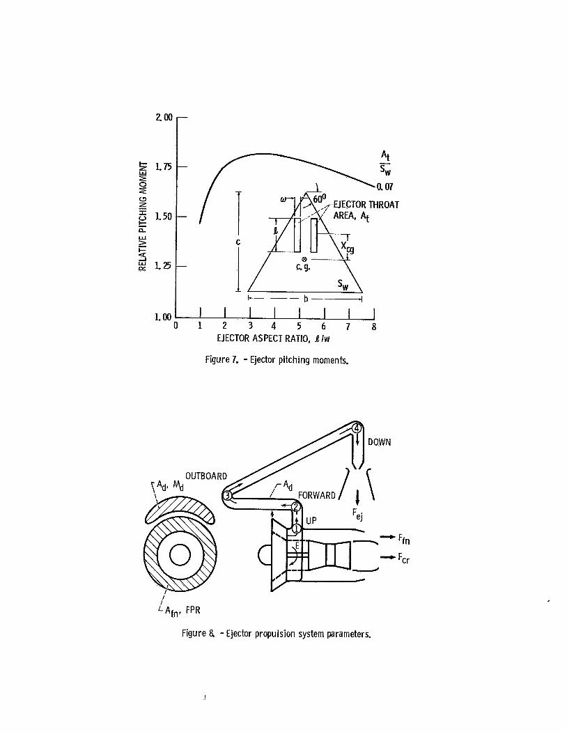
The p i t c h i n g moment an e j e c t o r o f a g iven t h r o a t area w i l l produce depends on i t s l e n g t h t o w id th r a t i o , l /w. Typ ica l r e s u l t s f o r A t /% = 0.07 a r e shown i n f i g u r e 7 An l /w o f about 3.5 y i e l d s t h e maxlmum p l t c h i n g moment although the maximum i s f l a t A l a r g e r l/w, say 5, reduces t h e blockage t h a t t h e e j e c t o r d i s - charge causes t o the f r e e stream a i r f l ow ing under the wtng wi th l l t t l e reduct ion i n p i t c h i n g moment from t h e optimum
The sketch i n f i g u r e s 5 and 7 has an A t / % = 0 07 and an l / w = 5.0
Thrust Per Fan Plus Duct F ron ta l Area
For an a i r c r a f t t o have supersonic capab i l - i t y , a low f r o n t a l area o f t h e a i r c r a f t , which consis ts i n p a r t o f t h e propuls ion system f r o n t a l area, i s very impor tant So an important propul s ion system parameter i s t he t h r u s t per propul s ion system f r o n t a l area For the e j e c t o r system, the f r o n t a l area shown I n f i g u r e 8 i s made up o f t h a t p a r t o f t he f a n f r o n t a l area t h a t provides the e j e c t o r a i r , Afn, p lus the f r o n t a l o r cross sect ional area o f t he duct, Ad, which I n the assumed a i r c r a f t , passes over the fan t o d e l f v e r t he fan a i r t o the e j e c t o r
The cross sec t i ona l area o f t h e duct is determined by the mass f l o w i n the duct, and the duct f l ow Mach number, Md, which i n t u r n i s a func t i on o f the fan pressure r a t i o , FPR The choice o f duct Mach number I s a lso r e l a t e d t o the t o t a l pressure losses I n the duct which genera l ly Increase w i t h the duct Mach number squared The duct losses a re a l so p ropor t i ona l t o the number o f duct turns, whlch i n t h l s case i s t he primary source o f the losses The base- line e jec to r system being considered has four , 90° turns, i l l u s t r a t e d I n f i g u r e 8: (1) from the a f t a x I a l d l r e c t i o n e x i t i n g the fan t o upward, (2) from upward t o forward I n the duct passing over the fan, (3) from forward I n the fuselage duct t o outboard I n t o the wing where the e j e c t o r i s , and ( 4 ) f r o m outward t o downward as requi red t o serve as the downward t h r u s t i n g e j e c t o r primary
The r e s u l t s o f an analys is o f such a system a re shown i n f i g u r e 9 I n f i g u r e 9a, Fej/(Afn + Ad) i s p l o t t e d versus fan pres- sure r a t i o f o r several values o f duct Mach number A l a r g e value o f the o rd ina te i s des i r - ab le The curves show Increas ing Fej/(Afn + Ad) w i t h increas ing fan pressure r a t i o f o r a l l duct Mach numbers The e f f e c t o f the duct l oss may be seen f o r a Mg = 0 2 by comparing the dashed l i n e . whlch has no losses w i t h the s o l i d l i n e whlch has the duct t u r n i n g losses inc luded The duct Mach number optimtzes between MO = 0 2 and 0 3 Higher duct Mach numbers reduce the duct cross sec t i ona l area, which I s favorable, bu t a l so increase t h e losses which causes a decrease the t h r u s t , which i s unfavorable The t rade-of f between these t w o e f f e c t s r e s u l t s I n an optimum duct Mach number
3
Figure 9b presents the corresponding e j e c t o r t h r u s t d i v lded by t h e f a n s h a f t energy tnput. Fej/E. A h igh va lue corresponds t o a reduced f u e l consumption r a t e . Stnce t h e t a k e o f f and land ing t imes a r e short, t he re i s on l y a smal l q u a n t i t y o f f u e l invo lved I n any case, f o r f a n pressure r a t i o s between 3 and 4. t he re i s n o t an impor tant v a r i a t i o n tn Fej/E w i t h f a n pressure r a t t o o r duc t Mach number
Thrust Per Propuls ion Volume
The volume taken up i n t h e fuselage by t h e propuls ion system i s n o t a v a i l a b l e f o r payload o r f ue l , so a low volume propuls ion arrangement i s des i rab le F igure 10 shows two poss ib le a i r - c r a f t arrangements For both, t he englne i s near t h e center o f t h e a i r c r a f t and p rov i s ions a re made f o r t h e f a n a i r c o l l e c t l o n and duc t l ng t o a forward e j e c t o r f o r t akeo f f and landing I n t h e upper f i gu re , I n the c r u i s e mode, the f a n a i r i s ducted to , and exhausted a t t he rea r o f t h e a i r c r a f t Thts duc t i ng occupies conslder- a b l e fuselage volume I n t h e lower f i gu re , i n t h e c r u i s e mode, t h e fan a i r nozzle i s ad jacent t o t h e core nozzle. A l t e r n a t i v e l y , t h e f a n and core a i r could be mixed and exhausted through a common nozzle near the a i r f rame center Thts reduces the propuls ion system volume, b u t aggravates the fuselage angles i n the v i c i n i t y o f t he nozzles A d e t a i l e d study i s needed t o resolve such questions
Subsequent discussions w i l l deal w i t h these geometric arrangements t o achieve other ob ject tves
E lec to r P r o w l s i o n Options
Having presented the basel ine e j e c t o r a l r . c r a f t and some basic e j e c t o r propuls ion para- meters, the f o l l o w i n g discussion deals w i t h ways the propuls ion system can be modi f ied t o y i e l d greater t h r u s t performance, a cooler f o o t p r i n t , o r b e n e f i t from a l t e r n a t i v e propulston cyc le and then categorizes these modi f icat ions from a cyc le p o i n t o f view
Greater Performance
E jec to r Jet Def lect ion. Conslder the possi b i l i t y o f improving the a i r c r a f t performance a t l i f t - o f f , f l g u r e 11 The base a l r c r a f t a t l i f t - o f f condi t lons i s shown i n f i g u r e l l a The e j e c t o r j e t , Fe i s normal t o a i r c r a f t l ong i - t u d i n a l ax i s , d' = 0, and the l i f t - o f f I s assumed t o occur a t an a l r c r a f t angle o f attack, a = 200 The core j e t , F c r , 'IS a l s o de f l ec ted downward t o prov ide both l i f t and th rus t , and t o balance the a i r c r a f t p i t c h i n g moments Var ia t ions from the basel ine a re shown i n the other two f i gu res F igure l l b shows t h e e j e c t o r j e t de f l ec ted rearward so d = 40° Figure l l c shows the wing w i t h t r a i l i n g edge blowing so the des i red l l f t c o e f f i c i e n t can be achieved a t Q = Oo
The forces on an example a i rp lane, {se lected t o i l l u s t r a t e the p o i n t o f t he dlscusslon) i .e , l i f t , L; drag, D; and th rus t , F, as a f r a c t i o n o f t he a i r p l a n e gross weight, W, a re shown i n f i g u r e 1 2 as a f u n c t i o n o f t he forward ve loc i t y , V
d

I n f i g u r e 12a. l l f t - o f f can occur when L/W = 1 . O A t the l i f t - o f f ve loc i t y . about 110 fps. t he wing, the e jec to r , and de f l ec ted core j e t each prov ide about 1/3 o f t h e l i f t Wing supported f l i g h t can occur a t about 225 fps
The drag, f i g u r e 12b, i s made up o f t he a i r f rame drag, p l u s the engine core a i r ram drag, p lus the e j e c t o r ram drag The a v a i l a b l e t h r u s t i s made up o f t he core t h r u s t from the de f l ec ted core j e t and the reverse t h r u s t o f the e jec to r , reverse because i t i s blowing forward a t an angle corresponding t o the a i r c r a f t angle o f a t tack, a = 20° A minimum l e v e l o f T/W above O/W, o f about 0 06, i s requi red f o r a i r c r a f t a x i a l acce le ra t i on With no e j e c t o r de f l ec t i on , d = 0, and f o r t he selected a i r c r a f t t h r u s t t o weight r a t i o , t he margin o f t h r u s t over drag i s unacceptable a t l i f t - o f f , L/W = 1 0
An obvious way t o improve t h i s s i t u a t i o n i s t o d e f l e c t t he e j e c t o r j e t rearward, say by d = 400, which then y i e l d s a forward t h r u s t component equal t o t h a t which was the reverse t h r u s t component and the same l i f t The margin o f a i r c r a f t t h r u s t over drag a t l i f t - o f f i s now s i g n i f i c a n t l y improved, i t i s about 0 2 g ' s , a much more des i rab le l e v e l
The above d iscuss ion ra i ses several questions:
1 Is the e f f e c t i v e e j e c t o r j e t angle set on l y by the geometry o f t he e j e c t o r o r i s i t s i g n i f i c a n t l y e f fec ted by the ex te rna l f l o w f i e l d a t l i f t - o f f ? This needs t o be determined experimental ly
2 Can an e j e c t o r be designed w i t h a va r iab le d e f l e c t i o n c a p a b i l i t y w i t h l i t t l e l o s s i n e j e c t o r augmentation r a t i o ? This a l so requi res experimental study
Another approach i l l u s t r a t e d i n f i g u r e l l c i s t o generate the wing l i f t a t near zero angle o f a t tack by wing t r a i l i n g edge blowing and thus e l im ina te the e j e c t o r reverse t h r u s t e f f e c t However, there would s t i l l be an a i r c r a f t accel e r a t i o n advantage t o some a f t d e f l e c t i o n , e g , d = 20°, o f the e j e c t o r j e t
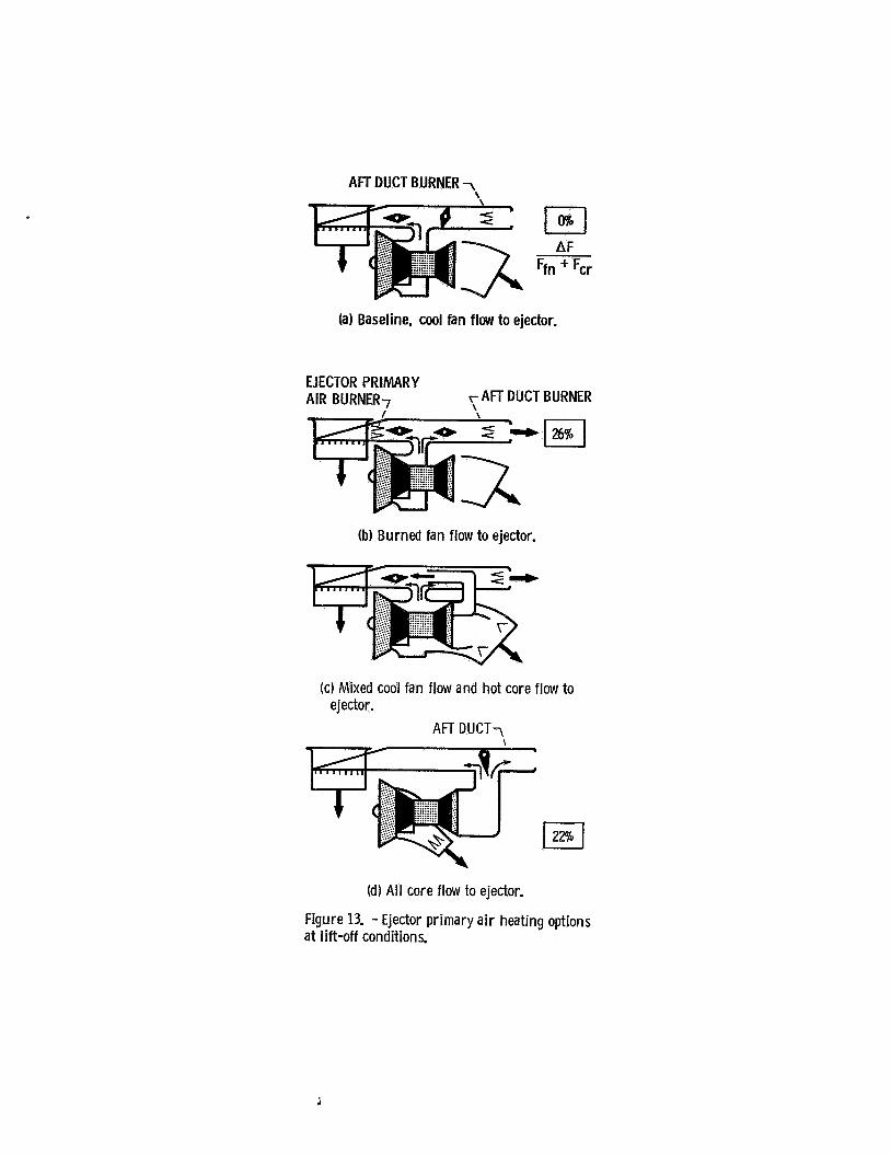
E jec to r Primary A i r Heating Plus A f t Fan A i r Burning. Another way t o improve the l i f t o f f performance i s t o heat t he primary a i r f o r the e jector , see f i g u r e 13
The basel ine e j e c t o r system uses unheated fan a i r when the e j e c t o r i s used, f i g u r e 13a. bu t an a f t duct burner i s used a t o ther times as described e a r l i e r I n the d iscuss ion o f f i g u r e 4
Before proceeding w i t h d iscuss ing t h i s opt ion, i t i s i n t e r e s t i n g t o note t h a t i n p r i n - c i p a l , primary a i r heat ing can be done w i t h no change i n e j e c t o r geometry, e i t h e r primary noz. z les o r secondary f l o w geometry This assumes t h a t t he primary nozzle pressure r a t i o remains constant (1 e , n e g l i g i b l e t o t a l pressure loss due t o combustion), t h a t i t i s s u f f i c i e n t t o choke the primary nozzle t h r o a t (genera l l y the case), and the e j e c t o r augmentation r a t i o rematns constant (i e , t h e primary and secondary mix ing are adequate) When the prtmary j e t i s heated
by a temperature r a t i o o f e f Tb/Tno b and the pressure r a t i o remains constant, t he e j e c t o r primary e x i t Mach number remains constant, b u t t he e x i t v e l o c i t y ( v ) increases by 4 because the speed o f sound .Increases by & The f l o w dens i t y decreases by e so the mass f l o w r a t e per u n i t area (m), which i s t he product o f v e l o c i t y and densi ty . decreases by 6. The primary th rus t , mv, i s then independent o f e and so i s t he e j e c t o r t h r u s t i f the augmentation r a t i o remains constant I n summary, i nc reas ing the primary a i r temperature a t constant t o t a l pressure does n o t a f f e c t the primary o r e j e c t o r t h rus ts , bu t reduces the primary mass f l o w r a t e by %
Now, i f the e j e c t o r primary a i r temperature i s increased, f o r example, by a f a c t o r e = 4, as by a burner as shown i n f i g u r e 13b,Prthe primary mass f l o w from the fan t o the e j e c t o r i s reduced t o h a l f The other h a l f o f the mass f l o w from the fan i s assumed t o discharge through the a f t fan a i r duct, a l so shown i n f i g u r e 13b. and can be augmented by burning by a r a t i o o f 2, corresponding t o gad - 4 0 The numerical values on the f i g u r e a re based on the sum o f t he fan and core t h r u s t s being 100% and an example engine w i t h a f a n t o core t h r u s t s p l i t o f Ffn/Fcr = 0 45 The values i n the boxes i n d i c a t e the poss ib le percent t h r u s t augmenta t i o n The example i n f i g u r e 13b shows a 31 percent t h r u s t augmentation
An a l t e r n a t i v e way o f heat ing the e j e c t o r primary a i r i s by mix ing i t w i t h the core flow, as i l l u s t r a t e d i n f i g u r e 13c
I n the l i m i t , f o r t he same fan t o core t h r u s t s p l i t used above, a l l the e j e c t o r primary a i r could be core f low, f i g u r e 13d The fan f l o w e x i t i n g the fan a i r nozzle can be burned, y i e l d i n g a t h r u s t augmentation o f 31 percent
One o f the advantages o f using the core a i r f o r the e jec to r and i n the a f t duct, as i n f i g u r e 13d, can be understood by considering the take. o f f sequence o f events F o r acce le ra t i on down the runway, the ho t core a i r I s d i rec ted rear- ward i n the a f t duct The fan a i r i s d i rec ted rearward by the lower va r iab le d e f l e c t i o n noz- z l e The fan a i r can be burned The burn ing i s i n i t i a t e d a t t h e s t a r t o f t he ground run and continues through l i f t - o f f and t r a n s i t i o n t o wingborne f l i g h t A t l i f t - o f f , most o f t he core f low i s d i rec ted t o the e jec to r , and the burned fan f l o w i s de f l ec ted downward by the lower va r lab le d e f l e c t l o n nozzle Thls system avoids the burner l i g h t requi red a t l i f t - o f f by the systems ind i ca ted by f i g u r e 13b, f o r t he burn ing o f the fan e j e c t o r primary a i r , and i n f i g u r e 13c f o r the burn ing o f t he fan a i r e x i t i n g the va r iab le d e f l e c t i o n core nozzle
I n comparing the options f o r heat ing the e j e c t o r primary a i r , f an a i r burning, f i g u r e 13b, o r use o f the ho t core f low, f i g u r e 13d. f o r t he present example, they both g i ve the same t h r u s t augmentation, bu t the use o f the core a i r appears simpler from an engine p o i n t o f view b u t no t necessar i ly from an a i r c r a f t i n t e g r a t i o n p o i n t o f view
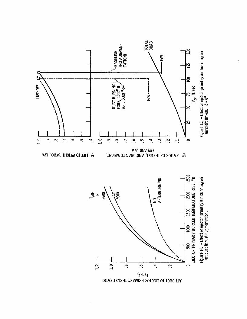
Figure 14 presents the t h r u s t augmentation f o r t h e e jec to r primary a t r burntng op t i on of
4

f i g u r e 13b i n a more general way It presents t h e e j e c t o r pr imary a i r t h r u s t augmentation r a t i o as a f u n c t i o n o f t h e burn ing temperature r i s e The example cond i t i on f o r f i g u r e 13b i s i nd i ca ted by t h e c i r c l e symbol An impor tant p o i n t from t h i s f i g u r e i s t h a t t he t h r u s t aug- mentation va r ies l i k e t h e square r o o t o f t h e temperature r i s e , t h a t i s , t h e i n i t i a l increment o f heat a d d i t l o n g ives t h e l a r g e r t h r u s t augmentation
The e f f e c t on t a k e o f f performance o f burn ing t h e primary a i r t o epr = 4 i n a propuls ion system l i k e 13b. i n an a i r c r a f t l i k e t h a t o f f i g u r e l l a , i s shown i n f i g u r e 15 A t t h e ZOO l i f t - o f f angle o f a t tack, t h e j e t ou t t he rea r o f t he a i r c r a f t , which does n o t e x i s t i n t h e base l i ne case a t l i f t - o f f , prov ides some l i f t which reduces the l i f t - o f f speed as shown i n f l g u r e 15a This r e s u l t s i n a lower drag a t l i f t - o f f , f i g u r e 15b The a f t j e t a l s o provides l a r g e amount o f t h r u s t so t h a t t h e t h r u s t over drag margin i s s i g n i f i c a n t l y improved over t h e basel ine case, f i g u r e 15b.
I n summary, two techniques f o r improving l i f t - o f f performance have been discussed- (1) e j e c t o r j e t a f t d e f l e c t i o n a t l i f t - o f f , and (2) hea t ing o f t h e e j e c t o r prlmary a l r by burn ing o r by us ing engine core f l o w Both o f f e r s i g n i f i - can t l i f t - o f f t h r u s t enhancement, b u t a t t h e expense o f increased complexity, and probably weight
Next, we w i l l consider coo l i ng t h e f o o t p r i n t
Cooler Foo tp r in t
One o f the advantages o f t he basel ine e jec- t o r system over some o f t he other STOVL concepts i s t he cool, low ve loc i t y , f r o n t f o o t p r i n t generated by the e j e c t o r The subject of t h i s d iscuss ion and f i g u r e 16 are some o f t he poss i . b i l i t i e s f o r reducing the temperature o f the a f t o r core f o o t p r i n t o f the basel ine a i r c r a f t , f i g u r e 16a
Ejector Primary A i r Burnins and Fan and Core A i r Mlxing: I n the preceding sec t i on i t was pointed out t h a t i f the fan a i r going t o t h e e j e c t o r primary i s heated by a temperature r a t i o o f 4, then h a l f o f t he fan a i r i s a v a i l a b l e f o r o ther purposes For t h e present purpose, t h e coo le r primary a i r can be mixed w t t h the core f low, f i g u r e 16b, t o reduce the j e t temperature from 150OoF t o llOO°F Thls method y i e l d s improved l i f t - o f f performance, b u t a l s o a small increase i n the e j e c t o r j e t temperatures f o r t he reduct ion i n core j e t temperature
E jec to r Primary From Core Jet : Another approach which was discussed i n the preceeding section, f i g u r e 13d. which can a l s o be used t o reduce the j e t temperatures, i s t o use t h e engine core j e t f o r t he e j e c t o r primary f low; and the cool , unburned f a n f l o w f o r t he a f t j e t , f l g u r e 16c The a f t j e t i s now q u i t e cool, 28OoF, and the e j e c t o r j e t average temperature i s 1400F. compared w i t h 1500°F f o r t he o r l g i n a l core f low, f l g u r e 16a This gives one o f t he coolest arrangements
The dlsadvantages o f t h i s arrangement a re the h o t core f l o w duct lng, and t h a t t h e warmer
temperatures t h a t a r e now forward a re more l i k e l y t o be ingested by t h e englne i n l e t
Second E lec to r f o r t he Enslne Core Flow: A d i r e c t approach t o coo l i ng the core f l o w i s t o add a second e j e c t o r around t h e core f low, f i g u r e 16d I t s primary purpose i s t o cool t h e j e t and secondar i ly t o augment i t s t h r u s t Such an e j e c t o r was dlscussed i n reference 6 I t may reduce t h e core temperature from l50O0F t o 900°F, f o r example.
The XFV-12A System: I n t h i s system7 t h e f a n and core a i r a r e f i r s t mixed, thus c o o l i n g t h e core f l o w and then t h e e n t i r e engine f l o w becomes t h e primary f l o w f o r e jec to rs so t h e primary temperature I s f u r t h e r reduced by t h e e j e c t o r secondary f l ow .
F igure 17 shows how t h e e j e c t o r and mixed core exhaust f l o w temperatures vary w i t h t h e e j e c t o r primary a i r burn lng temperature r i s e f o r t h e engine arrangement o f f i g u r e 16b As w i t h t h e t h r u s t augmentation, t h e I n i t i a l increments I n primary a-lr burn ing r e s u l t i n the l a r g e r mixed core f l o w temperature reductions
I n summary, t he basel ine e jec to r system has the advantage o f a cool f r o n t f o o t p r i n t Two o f t he schemes discussed r e s u l t i n s l i g h t l y h ighe r f r o n t f o o t p r i n t temperature t o reduce the a f t f o o t p r i n t Adding a second e j e c t o r on the core j e t f o r coo l i ng it, maintains the cool base l i ne f r o n t f o o t p r i n t temperature The XFV-1ZA system o f mix ing t h e f a n and core f lows and us ing a l l t h i s f low as the primary f l o w f o r e jec to rs pro- bably r e s u l t s i n t h e lowest average temperature
Propulsion Cycles
There appears t o be th ree categories o f propuls ion cycles, shown i n f i g u r e 18, o f primary i n t e r e s t f o r e j e c t o r propuls ion systems A l l t h e engines discussed thus f a r are two-spool turbofan englnes, f i g u r e s 18a, b, and c F igure 18d i s t he newest and most unique o f t he engine cyc les
Separate Fan and Core Flow: I n the basel ine system, f i g u r e 18a, t he fan and core f lows a r e always separate Thls gives the greatest freedom t o opt imize the choice o f fan pressure r a t l o and engine bypass r a t i o I t may a l so requ i re the g rea tes t propuls lon system volume i n the a i r - c r a f t i f l t requ i res t h e fan a i r a f t duct, shown i n f i g u r e 10a
An a l t e r n a t e arrangement t h a t maintains separate fan and core f low i s t o duc t a l l t he core f l o w t o the e j e c t o r o r ou t t h e a f t duct, f i g u r e 18b The engine cyc le must be selected t o y i e l d des i rab le e j e c t o r primary f l o w charac- t e r i s t i c s The f a n a i r i s always exhausted through a v a r i a b l e d e f l e c t l o n nozzle on t h e underside o f t he a i r c r a f t , so the f a n and core f lows always remain separate
SeparateKonf luent Fan and Core Flow: I n t h l s scheme, f i g u r e 18c, t he fan and core f lows a re separate du r ing e j e c t o r operation, b u t a r e confluent du r ing the takeo f f ground r o l l , and du r ing up-and-away operat lon This system reduces the core exhaust temperature when t h e two stream are mixed, and reduces the propuls lon system volume on the a i r c r a f t
5 i

Its cycle optimization may be restricted by the requirement for core and fan static pressure matching during confluent operatlon. and the problem of low body surface angles for low super- sonic drag may be aggravated
Another option is to keep the core and fan flows separate even though exhausting adjacently
The above systems all require two spool turbofan engines The following system is sin- gle spool
Turbine Bypass Engine and TurbocomDressor Stage; The turbine bypass engine, references 2 and 3. figure 18d. is a single spool engine like a turbojei, but i s characterized, typically. by 15 percent compressor bleed at a compressor pressure ratlo of about 16 at full throttle at takeoff or landing condition This bleed air can be used to drive a turbocompressor unit, TC, figure 18d. which produces flow at a pressure ratio of 3 5 to 4 0 which in turn may be used as the primary air for the ejector When not used for the ejector, the TC jet can be used for acceleration during the ground roll and for combat maneuvers This is a relatively new concept and needs further evaluation
Concludinq Remarks
The Initial discussion shows the baseline ejector aircraft prefers high pressure ratio fans, FPR = 3 5 to 4 0, and can benefit from an increase In primary air temperature Beyond this, there are a number of options for growth or advancement in aircraft characteristics over those o f the baseline, but usually at the expense of jncreased complexity and possibly increased weight
Improved aircraft llft-off performance can be obtained by: (1) adjustable ejector jet aft deflection and (2) ejector prlmary air heating by burning or the use of the hot core flow
Cooler aft, or core, footprints can be approached in a number of ways, for example, (1) by mixing or djsplacing the hotter core flow with the cooler fan flow, or (2) by a core air cooling ejector
The single spool turbine bypass engine with turbocompressor unit which provides air at the desired pressure for the ejector primary and thrust for combat maneuvers is an alternative to the twin spool fan engine
Finally, the baseline delta wing -ejector configuratlon is a valuable, relatively simple. startlng point for many possibilities for enhanced performance, cooler footprints. and advanced engine cycles
References
1 Kidwell. G H , Jr and Lampkln, B A , "An Evaluation of Supersonic STOVL Technology," AIAA Paper 83-2493, Oct 1983
2 Sheridan. A E , "The Applicatlon of Turbine Bypass Engines to High Performance V/STOVL Aircraft," AIAA Paper 83-2512, Oct 1983
3 Franciscus. L C , 'Supersonic STOVL Air- craft With Turblne Bypass/Mass Flow Ampll- fier Englnes," AIAA-84.1403, June 1984
4 Zola, C L , Wilson. S L , 111. and Eskie, M A , "Tandem Fan Applications in Advanced STOVL Fighter Configurations.' AIAA- 84-1402, June 1984
5 Foley, W H , Sheridan, A E , and Smith. C H., "Study of Aerodynamlc Technology for Slngle-Cruise-Engine V/STOVL Fighter/Attack Aircraft." NASA CR 166268, Feb. 1982
6, Wlllis. W . S . , Konarski, M , and Sutherland. W. V , "Conceptual Design, Evaluation and Research Identification for Remote Augmented Propulsive Lift Systems (RALS) With Ejectors For VTOL Aircraft." General Electric Co , Cincinnati, OH, R82AEB315, May 1982 (NASA CR- 167906)
1 Braden, R P , Nagaraja, K S , and Von Ohain. H J P , "Proceedings. Ejector Workshop for Aerospace Applications," AFWAL- TR- 82-3059, June 1982
i 6

t t REMOTE AUGMENTED LIFT SYSTEM m-mu TANDEM FAN SYSTEM
Figure 1. - Supersonic STOVL propulsion. C-82-1659
EJECTOR SYSTEM CD-82-12WB DEFLECTED THRUST SYSTEM
Figure 2. - Supersonic STOVL propulsion. C-82-1658
J

MODEST PRIMARY PRESSURE RATIO ,USED FOR THIS STUDY WITH
STEADY PRIMARY REFERENCE ROTATING PRIMARY "PRIMARY" PULSED PRIMARY
HIGH PRIMARY PRESSURE RATIO
(SUBSONIC SECONDARY FLOW) FOLLOWING ASSUMPTIONS :
EJECTOR
NOZZLE
SUPERSONIC SECONDARY TWO STAGE
BLOWN OR UNBLOWN DIFFUSERS
ACOUSTICALLY ENHANCED MIXING
Figure 3. - Ejector types.
Figure 4. - Ejector propulsion modes for supersonic STOVL.

C
A- EJECTOR THROAT KEY PARAMETERS
EJECTOR HOLE SIZE IN WING
&ISw ,., l/CFej/&)
EIECTOR PITCHING MOMENT
Figure 5. - Ejector and wing geometries.
700
600 e- >- 500 La
% -
s400 CY a I- 300 a
200 0 CY I- I-
Ly:
2.
2 100
0
r
1 PRIMARY
TEMPERATURE, I GAS
OR I I
0 .1 .2 . 3 . 4 .5 .6 .7 . 8 SECONDARY FLOW THROAT MACH
NUMBER, Mt
Figure 6. - Ejector thrust per thoat area. Sea level static conditions.
1.50
1.25
I-- -- b -+ 1.00
0 1 2 3 4 5 6 7 8 EJECTOR ASPECT RATIO, a Iw
Figure 7. - Ejector pitching moments.
I
i A f n , FPR
Figure 8 - Ejector propulsion system parameters.

2 50 225 ZOO 1.75 1.50 1.25 LOO -75 .50 .25
0
4 5
4.0
3.5
3.0
2.5
2.0
1.5
1.0
17- LOSSES DUE TO DUCTING
1 2 3 4 5 FAN PRESSURE RATIO
Figure 9. - Ejector t h rus t per frontal area and fan power i n p u t
,.' ""7 I
r' I 0" I I
(a) Fan a i r exhausted at rear of aircraft.
(b) Fan a i r exhausted adjacent to core nozzle.
Figure 10. - Effect of fan a i r ducting on available fuselage volume.

Mla ONb' 'MlJ 'Ml'W 'lH31lM 01 3Vda M / l 'OIlVtl lH313M 01 Uil - - m aNV 'ISfldHl 'WnlNlbOW 11x3 40 SOllVtl Z
vi .- x m
0' 8 I1
Lo -- m -
a,
AFT DUCT BURNER 7,
m AF
Ffn + Fcr
(a) Baseline, cool fan flow to ejector.
EJECTOR PRIMARY AIR BURNER, r AFT DUCT BURNER
(b) Burned fan flow to ejector.
(c) Mixed cool fan flow and hot core flow to ejector.
AFT DUCT7 \
(d) All core flow to ejector.
Figure 13. - Ejector primary a i r heating options at l ift-off conditions.
O 1 0 0 h \ O m d O O 1 m h \ O m d m N A 0 . . . . . . . * A s - -
. . . . M/a aNV M/d
’1H313M 01 3tllla (INV ‘lSIIl!HlJO SOlltlll MI1 ’OllVll lH313M 01 Ull Z
L m .-

AFT DUCT BURNER-, I
(a) Baseline, cool fan flow to ejector.
E T =
T = iiooo F
(b) Mixed cool fan and core flows.
AFT DUCT? \
T = 280' F
(c) All core flow to ejector
AFT DUCT BURNER 7 I
T = 9 0 O 0 F
(d) Core flow cooling ejector.
Figure 16. - Exhaust jet cooling options at lift-off conditions.

t r-
I- o 3 n t a
1 1
I
L
8 h 8 m 8 0 Ln
0
b-4 x b-4
8 Ln 4
0
1. Report No.
NASA TM-83641
Supersonic STOVL Ejector Aircraft from a Propulsion Point of View
2. Government Accession No.
7 Author@)
R. Luidens, R. Plencner, W. Haller, and A. Glassman
@. SOCUdtY ClMSlf. (Of thl8 fopoft)
Unclassified
9. Performing Organization Name and Address
National Aeronautics and Space Administration Lewis Research Center Cleveland, Ohio 44135
National Aeronautics and Space Administration Was h i ngton , D . C. 20546
2. Sponsoring Agency Name and Address
#). WUdty ClMSff. (Of this me) 21. No. of pages 22. Price.
Uncl ass i fi ed
5. Supplementary Notes
3. Recipient's Catalog No.
5. Report Date
6. Performing Organization Code
505- 40- 82 8. Performing Organization Report No.
E- 2084 IO. Work Unit No.
11. Contract or Grant No.
13. Type of Report and Period Covered
Technical Memorandum 14. Sponsoring Agency Code
Prepared for the Twentieth Joint Propulsion Conference cosponsored by the AIAA, SAE, and ASME, Cincinnati, Ohio, June 11-13, 1984.
6. Abstract
The paper f i rs t describes a baseline supersonic STOVL ejector a i r c ra f t , including i t s propulsion and typical operating modes, and ident i f ies important propulsion parameters. Then a number of propulsion system changes are evaluated i n terms o f improving the l i f t -off performance; namely, a f t deflection of the ejector j e t and heating o f the ejector primary a i r e i ther by b u r n i n g o r u s i n g the hot engine core flow. cases of m i x i n g or interchanging the fan and core flows, and u s i n g a core flow ejector. turbine bypass engine plus a turbocompressor t o supply the ejector primary a i r , and thrust d u r i n g take-off combat.
The possibi l i ty for cooling the footprint i s i l lus t ra ted fo r the
Finally, the application of a new engine concept is presented, the
7 Key Words (Suggested by Author@)) 18. Dlstrlbution Statement
STOVL Ejector
Uncl assi f i ed - u n l imi ted STAR Category 07