superrack-installationguide
TRANSCRIPT

Removable Docking Modulesfor IDE or USB Devices
Installation Manual
www.vipower.comViPowER

PROPRIETARY NOTICE
ViPowER, Inc. makes no warranty of any kind with regard to thismaterial, including, but not limited to, the implied warranties ofmerchantability and fitness for a particular purpose. ViPowER Inc.shall not be liable for errors contained herein or for incidental orconsequential damages in connection with the furnishing, performance,or use of this material.
This document contains proprietary information which is protected bycopyright. All rights are reserved. No part of this document may bephotocopied, reproduced, or translated to another language without thewritten consent of ViPowER Inc. The information contained in thisdocument is subject to change without notice.
Super Rack is a trademark of ViPowER, Inc. Mac is a registered trademark of AppleComputer, Inc. Windows is a registered trademarks of Microsoft Corporation.All other trademarks belong to their respective owners.Patent: USA: 5694290
Taiwan: 126661 & 129379Germany Nr. 297 15 551.2 & Nr. 297 22 974.5Japan: 3047936 & 3050489China: ZL 97 2 03156.1
Patent Pending: U.K, France, Korea
© Copyright 2003 by ViPowER, Inc.
02/01A
1-1 Introduction ....................................................................... 1 Super Rack Features ...................................................... 3
System Requirements ..................................................... 3 Unpacking Your Super Rack ............................................ 4 IDE Basics ..................................................................... 4
USB Basics ................................................................... 4
2-1 Hardware Installation ........................................................... 5Super Rack Components ............................................... 5Installing the Super Rack Out-Frame ............................... 6Installation for USB Interface ......................................... 7Mounting a Drive in the In-Tray Box (VP-15) ..................... 9
3-1 Using the Super Rack with IDE Devices ............................... 11
4-1 Using the Super Rack with USB Devices .............................. 12
Table of Contents

1-1 IntroductionCongratulations on your purchase of an ATA 33/66/100/133 Super RackRemovable Docking Module. The Super Rack is a convenient, versatile solutionfor portable, interchangeable usage of both IDE and USB devices with yourUSB-equipped PC or Mac computer.
The Super Rack is form-fitted for a standard 5.25" half-height bay. When installed inyour computer, it provides the ATA 33/66/100/133 interface for hot-swappingany IDE in-tray box (with IDE devices such as 3.5”/2.5” HDD, LS-120, MO,TR-4 tape, ATA flash memory reader, and zip drives installed) or any USB in-traybox (such as hub, fax/modem, memory card readers and TV/FM/capture/cablemodels).
The Super Rack includes an IDE interface in-tray (VP-15) which can accept most half-height 3.5" and 2.5" drives (with separately purchased adapter cables). Not beinglimited by memory size, you can install any capacity drive. USB interface in-traybox models must be purchased separately.
This manual will guide you through the installation of the following Super RackRemovable Docking Modules.
Model Number Code Descriptions for Ordering Information:
V P - 1 0 L S F U - X 1 2 3 4 5 6 7 81 ViPowER .............. VP2 Interface Type ...... 1 = IDE, 2 = SCSI, 3 = Wide SCSI3 Body ...................... 2 = Out-Frame, 5 = In-Tray Box, 0 = Frame + Tray4 Lock Type ............. L = Latch-lock, K = Key-lock5 Power Switch ........ S = Latch Switch, P = Power Switch6 Cooling Fan .......... F = Fan7 USB Solution ........ U = USB8 UDMA.................... X =UDMA 33/66/100/133
Super Rack Installation Manual 1

Super Rack Models:
VP-10KUVP-10KFUVP-10KPFUVP-10KP2FUVP-10LSUVP-10LSFUVP-10LS2FUVP-410KP2FUVP-410LS2FUVP-410LXVP-410KPFUVP-410LSFUVP-15VP-15F
Super Rack Compatible USB In-tray Models(Optional USB Accessories):
VP-15HVP-15H2VP-15RVP-15TVVP-1528
Optional IDE Accessories:
VP-1536VP-1564H2AT
2 Super Rack Installation Manual
IDE/USB interface, Key-lockIDE/USB interface, Key-lock with One FanIDE/USB interface, Key-lock Power Switch with One FanIDE/USB interface, Key-lock Power Switch with Two FansIDE/USB interface, Latch-lock/Slide SwitchIDE/USB interface, Latch-lock/Slide Switch with One FanIDE/USB interface, Latch-lock/Slide Switch with Two FansIDE/USB interface, Key-lock Power Switch with Two FansIDE/USB interface, Latch-lock/Slide Switch with Two FansIDE/USB interface, Latch-lock/Slide Switch with Two FansIDE/USB interface, Key-lock Power Switch with Ball FanIDE/USB interface, Latch-lock/Slide Switch with Ball FanIDE interface, In-Tray BoxIDE interface, In-Tray Box with One Fan
USB 1.1 4-port HubUSB 2.0 4-port Hub (requires USB 2.0 equipped computer)USB CF/MS/MMC/SM/SD/MD Memory Card ReaderUSB TV/FM/Capture/Cable TVUSB 2.0 to IDE Mobile RACK Shuttle
3.5” to 2.5” HDD converterIDE Ultra DigiREADer (Flash Card Reader)

Super Rack Features• Compatible with PC or Mac tower or desktop models, external subsystem
& RAID system cases
• Form-fitted for a standard 5.25-inch half-height bay
• IDE in-tray box (VP-15) enables portable use of fixed 3.5-inch and2.5-inch (with separately purchased adapter cables) hard disk drives,LS-120, MO, TR-4 tape, zip and other IDE and ATAPI devices
• USB support for portable use of USB hub, fax/modem, CF/SM/MS/MMC/Micro Drive/SD memory card readers and TV/FM/Capture in-tray modules
• Convenient pull-out handle
• Safety lock feature
• Power on/off feature
• LED indicator for power and drive activity
• Built-in cooling fan
• The in-tray box is interchangeable between all models
• Fully compatible with Windows® 98 or later; Mac OS 8.6 or later
• Dimensions: 8.4" (D) x 5.8" (W) x 1.6" (H)
System Requirements• Tower or desktop models, external subsystem & RAID system cases with
standard 5.25-inch half-height drive bay
• USB feature requires a USB-equipped PC or Mac computer with availableUSB port
Super Rack Installation Manual 3

4 Super Rack Installation Manual
Unpacking Your Super RackBefore installing the Super Rack, verify that the following items are included in thecarton. If any parts are damaged or missing, please contact your local dealer or salesrepresentative immediately.
1. One Super Rack Removable Docking Module2. Twelve mounting screws3. 2 keys (for key-lock models only)4. I/O expansion bracket with USB connectors (for USB accessory package:VP-1528, VP-15R, VP-15H, VP-15H2, VP-15TV)5. One user’s guide
IDE BasicsIDE is an acronym for Integrated Device (Drive) Electronics and is sometimes referredto as an ATA (AT Attachment) interface. It is the most commonly used interface for harddisk drives installed on personal computers. Other devices like CD-ROM, tape, op-tical drives, and so on have adapted a variation called ATAPI (ATA Packet Interface)and can be intermixed with standard IDE drives because they use the same cabling andelectrical interface.
Most systems today have two IDE channel connectors that are typically referred to asprimary and secondary ports. Each IDE port can have a maximum of two devices thatmust be uniquely identified, typically by the setting of a jumper as a ‘master’ or‘slave’ device.
USB Basics (USB function only come with USB accessory)USB is an acronym for Universal Serial Bus, a standard developed to replace the agingserial and parallel ports on existing computers. Using only one IRQ and designed asa hub architecture, it can support up to 127 devices. After loading the appropriatedevice driver(s), USB offers true plug-n-play and hot-swapping capability. A USBdevice can be plugged and unplugged from most systems at any time and anywhere onthe USB network. All connected devices on the bus can run simultaneously.
First release version USB 1.1 is defined as an intermediate speed bus and operates ateither 12 Mbps or 1.5 Mbps, depending on the attached device. Typical USB devicesinclude printers, modems, pointing devices, scanners, cameras, keyboards, memorycard readers, speakers and more.
The latest release version USB 2.0 is designed to increase data through out up to480 Mbps... 40 times faster than USB 1.1. Supporting multiple high-speedperipherals without worrying about a bandwidth bottleneck, it is also backwardcompatible with all USB 1.1 hardware.

Super Rack Installation Manual 5
Drive ActivityLED Indicator
Power ON/OFFLED Indicator
Latch-Lock Super Rack Out-Frame Model (VP-12LSFU)
MountingHoles
Latch-Lock/PowerSwitch
Drive ActivityLED IndicatorPower ON/OFF
LED Indicator
Key-Lock Super Rack Out-Frame Model (VP-12KPFU)
MountingHoles
Key-Lock/Power Switch
2-1 Hardware InstallationThe Super Rack Docking Module is designed to install in any PC or Mac computerwith an available 5.25-inch half-height drive bay. General instructions for installingthe Super Rack are given since the design of computer cases varies. Refer to yourcomputer’s manual whenever in doubt.
Super Rack ComponentsThe Super Rack is comprised of two components:
Out-Frame [VP-12LS (KP) FU]In-Tray Box (VP-15)

6 Super Rack Installation Manual
Super Rack In-Tray Box VP-15 (with cover removed)
PowerConnector Data Interface
Cable
BottomMounting Holes
SideMounting Holes
Handle
Removable Front Panelfor Removable Media Drives
Installing the Super Rack Out-Frame1. Turn OFF the power to your computer and any other connected peripheral devices.
Follow the precautions for static electricity discharge:• Discharge any static electricity build up in your body by touching a grounded
metal surface such as the computer case, if plugged in.• During installation procedures, avoid any contact with internal parts.
2. Unplug the power cord from the back of the computer.
3. Remove your computer’s cover.
4. Remove the computer’s front cover plate from the 5.25-inch drive bay you planto install your Super Rack into.
5. Remove (separate) the Super Rack in-tray box from the out-frame by liftingthehandle and pulling it out.
6. Slide the out-frame into the selected 5.25-inch drive bay of your computer.
MountingScrews
MountingScrews
Out-Frame(All Models)
Install the Super Rack Out-Frame into the Drive Bay

Super Rack Installation Manual 7
7. Position the out-frame so its mounting holes align with the drive bay’smounting holes. Secure with the supplied mounting screws (two oneach side.)
8. Attach an existing IDE 40-pin data cable from the system motherboard (or IDEcontroller card) to the 40-pin connector on the back of the out-frame.
Most connectors are keyed for proper insertion. If there is no key, orient thecable so the pin-1 colored stripe edge is closest to the power connector.
9. Connect an available 4-pin power cable from the system’s power supply to the 4-pin connector on the back of the out-frame. The power connector is‘D’ shaped to ensure proper orientation when making the connection.
Continue to the next section before replacing the computer’s cover and reconnectingthe power and other external cabling.
Out-Frame Data Cable and Power Connectors
4-pin Power Connector
USB Connector
40-pin IDE Connector
Pin 1
Installation for USB Interface (optional)Your computer must be USB-ready in order to implement the USB feature of yourSuper Rack. An I/O expansion slot bracket with a USB interface cable is supplied forconnecting the Super Rack out-frame to an available USB port on your computer.
Connect toUSB Porton Computer
Connect toUSB Connectoron Super Rack Out-Frame
USB I/O Expansion Slot Bracket (optional)(for USB accessory package:VP-1528, VP-15R, VP-15H, VP-15H2, VP-15TV)

8 Super Rack Installation Manual
Perform the following steps to enable the USB function of the Super Rack.
1. With the computer cover removed, ensure the power is OFF, and all powercords and cables from the back of the computer are unplugged.
2. Select an unused I/O expansion slot at the back of your computer and removeits slot cover. Save its screw for securing the USB slot bracket.
3. Install the USB slot bracket and secure with the previously removed screw.
4. Connect the small 5-pin connector on the bracket to the USB connector onthe back of the Super Rack out-frame.
5. Replace the computer’s cover and reconnect the power and other cableconnections.
6. Plug the bracket mounted USB connector into any available USB porton your computer.
The following figure illustrates the USB connectors used to connect the installedSuper Rack to the USB port on the computer.
USB Connections Between Computer and Super Rack(for USB accessory package:VP-1528, VP-15R, VP-15H, VP-15H2, VP-15TV)
Connection toSuper Rack Out-Frame(Installed in Computer)
MountingScrew
USB BracketInstalled inExpansionSlot
USB Connector toComputer’s USB Port
Super RackOut-Frame

Super Rack Installation Manual 9
Mounting a Drive in the In-Tray Box (VP-15)Proceed with the following steps to install a 3.5-inch drive device in the in-tray box.(Note: a special adapter kit is required in order to install a 2.5-inch drive.)
1. Remove the in-tray box cover by sliding it towards the back of the unit.
Remove the In-Tray Box Cover
Slide Cover Off
2. If you plan to install a drive that features removable media such as a zip, TR-4 tape,MO, LS-120 drive, or ATA Flash memory reader, remove the center part of thefront panel.
Remove Front Panel for Removable Media Drives
IMPORTANT3. If you are installing a new hard drive into the in-tray box, you may need to
configure the drive before you install it. Refer to the drive manufacturer’s docu-mentation and configure the drive as ‘Master’, ‘Cable Select’, or ‘Slave’depending on the configuration of your computer. After you complete thisinstallation, you may also need to re-configure the computer’s BIOS Setup tomake the drive functional in the system.
Center Partof Front PanelRemoved

4. Connect the cables from the in-tray box to the appropriate pin connectorsof the drive.
The in-tray box’s 40-pin IDE cable supports 3.5-inch drives. Attach the powerand IDE cables from the in-tray box to the drive. The power connector is ‘D’shaped to correctly orient the connector. The colored stripe on the IDE cableshould be closest to the power connector.
To install a 2.5-inch drive, you must purchase a ‘44-pin to 40-pin’ connectoradapter from your local computer dealer.
5. Carefully position the drive inside the in-tray box.
6. Secure the drive in place using the supplied mounting screws. Use the mountingholes on the sides or bottom, depending on the design of the drive.
10 Super Rack Installation Manual
Install the Drive in the In-Tray Box
Colored Stripe
MountingScrews
Power Cable
In-Tray Box Ready for Use
MountingScrews Data Cable
7. Slide the in-tray box’s cover back on.
The hardware installation is complete. Your in-tray box is ready to use.
Super Rack Installation Manual 11
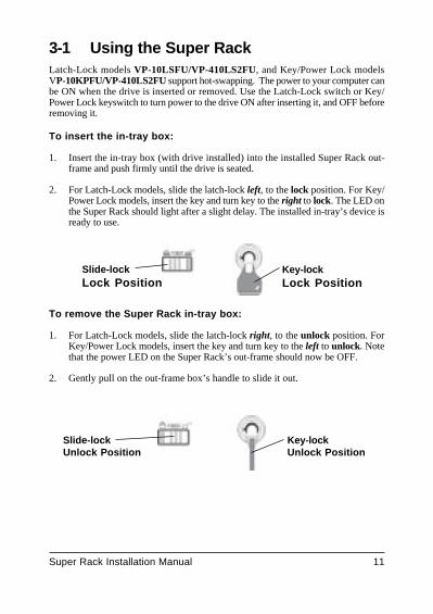
3-1 Using the Super RackLatch-Lock models VP-10LSFU/VP-410LS2FU, and Key/Power Lock modelsVP-10KPFU/VP-410LS2FU support hot-swapping. The power to your computer canbe ON when the drive is inserted or removed. Use the Latch-Lock switch or Key/Power Lock keyswitch to turn power to the drive ON after inserting it, and OFF beforeremoving it.
To insert the in-tray box:
1. Insert the in-tray box (with drive installed) into the installed Super Rack out-frame and push firmly until the drive is seated.
2. For Latch-Lock models, slide the latch-lock left, to the lock position. For Key/Power Lock models, insert the key and turn key to the right to lock. The LED onthe Super Rack should light after a slight delay. The installed in-tray’s device isready to use.
To remove the Super Rack in-tray box:
1. For Latch-Lock models, slide the latch-lock right, to the unlock position. ForKey/Power Lock models, insert the key and turn key to the left to unlock. Notethat the power LED on the Super Rack’s out-frame should now be OFF.
2. Gently pull on the out-frame box’s handle to slide it out.
Key-lockLock Position
Slide-lockLock Position
Key-lockUnlock Position
Slide-lockUnlock Position

12 Super Rack Installation Manual
Example USB 1.1 4-port Hub ( VP-15H )(Comes with USB I/O Expansion Slot Bracket)
4-1 Using the Super Rack with USB In-Trays
Latch-Lock models VP-10LS series/VP-410LS series and Key modelsVP-10K series/VP-410K series support plug-n-play, hot-swapping of USB in-traydevices such as USB hub, fax/modem, memory card readers and TV/FM/capture/CardReader models. The power to your computer can be ON when the in-tray is insertedor removed. Use the Latch-Lock switch or Key/Power Lock keyswitch to turn powerto the in-tray box ON after inserting it, and OFF before removing it.
To insert the in-tray box:
1. Insert the in-tray box into the installed Super Rack out-frame and push firmlyuntil the in-tray is seated.
2. For model VP-10LSFU, slide the latch-lock left, to the lock position. For modelVP-10KPFU, insert the key and turn key to the right to lock. The LED on theSuper Rack should light after a slight delay and you may be prompted for aonetime installation of its USB device driver when first used. Follow the promptsand the device is ready for plug-n-play use from then on. Note that any deviceused with a USB Hub model (VP-15H/VP-15H2) is hot-swappable.
To remove the Super Rack in-tray box:
1. For Latch-Lock models, slide the latch-lock right, to the unlock position. ForKey/Power Lock models, insert the key and turn key to the left to unlock. Notethat the power LED on the Super Rack’s out-frame should now be OFF.
2. Gently pull on the out-frame box’s handle to slide it out.
Example:

Super Rack Installation Manual 13
Remark:
The USB I/O Expansion Slot Bracket come with accessory only(VP-1528, VP-15R, VP-15H, VP-15H2, VP-15TV)

Printed on recycled paper.