superhydrophobic surface: design...
TRANSCRIPT

SUPERHYDROPHOBIC SURFACE:
DESIGN, FABRICATION, AND APPLICATIONS
by
Liangliang Cao
B.S., Zhengzhou University, China, 2002
M.S., Zhejiang University, China, 2005
Submitted to the Graduate Faculty of
Swanson School of Engineering in partial fulfillment
of the requirements for the degree of
Doctor of Philosophy
University of Pittsburgh
2010

ii
UNIVERSITY OF PITTSBURGH
SWANSON SCHOOL OF ENGINEERING
This dissertation was presented
by
Liangliang Cao
It was defended on
September 16, 2010
and approved by
William J. Federspiel, Professor, Departments of Chemical and Petroleum Engineering,
Surgery, Bioengineering, Swanson School of Engineering
Sachin S. Velankar, Associate Professor, Department of Chemical and Petroleum
Engineering, Swanson School of Engineering
Sung Kwon Cho, Associate Professor, Department of Mechanical Engineering and Materials
Science, Swanson School of Engineering
Dissertation Director: Di Gao, Assistant Professor, Department of Chemical and Petroleum
Engineering, Swanson School of Engineering

iii
Copyright © by Liangliang Cao
2010

iv
Superhydrophobic surfaces are often found on plant leaves and insect wings in nature. Water on
these surfaces forms small beads with a high contact angle of greater than 150° and drips off
rapidly when the surfaces are slightly inclined. This interesting phenomenon has stimulated
extensive research to make artificial superhydrophobic surfaces and to employ them for a variety
of applications. A key challenge in making superhydrophobic surfaces is to tailor the
morphology of the surfaces in nanometer scales, which typically involves synthesis and
fabrication of materials at nanometer dimensions.
In this dissertation, I will first explain general design principles for fabricating
superhydrophobic surfaces, with a specific focus on how to fabricate superhydrophobic surfaces
on intrinsically hydrophilic materials. I will then present several fabrication methods developed
during my Ph.D. program for making artificial superhydrophobic surfaces following such design
principles. Finally, I will discuss initial results of our investigation on two promising
applications of superhydrophobic surfaces, namely, for anti-icing and hydrodynamic drag
reduction purposes, respectively.
SUPERHYDROPHOBIC SURFACE:
DESIGN, FABRICATION, AND APPLICATIONS
Liangliang Cao, Ph.D.
University of Pittsburgh, 2010

v
TABLE OF CONTENTS
ACKNOWLEDGEMENTS ................................................................................................ XIV
1.0 INTRODUCTION ............................................................................................................1
1.1 SUPERHYDROPHOBIC SURFACES IN NATURE ............................................1
1.2 WETTING ON SURFACES ...................................................................................2
1.2.1 Wetting on flat surfaces ................................................................................2
1.2.2 Wetting on rough surfaces ............................................................................3
1.2.3 Contact angle hysteresis ...............................................................................6
1.3 CONVENTIONAL FABRICATION OF SUPERHYDROPHOBIC SURFACES7
1.3.1 Creating a rough surface on a hydrophobic material .................................8
1.3.2 Modifying a rough surface with hydrophobic coatings ............................. 10
1.4 CHALLENGES...................................................................................................... 12
2.0 METASTBALE CASSIE STATE .................................................................................. 15
3.0 FABRICATION OF SUPERHYDROPHOBIC AND SUPEROLEOPHOBIC
SURFACES ON INTRINSICALLY HYDROPHILIC AND OLEOPHILIC
MATERIALS ................................................................................................................. 18
3.1 SUPERHYDROPHOBIC SURFACES ON INTRINSICALLY HYDROPHILIC
SILICON PILLARS .............................................................................................. 18
3.1.1 Experimental design and methodology ...................................................... 18
3.1.2 Results and discussion ................................................................................ 24
3.1.3 Conclusion ................................................................................................... 28
vi
3.2 FABRICATION OF NON-AGING SUPERHYDROPHOBIC SURFACES BY
PACKING FLOWER-LIKE HEMATITE PARTICLES .................................... 29
3.2.1 Experimental design and methodology ...................................................... 29
3.2.2 Results and discussion ................................................................................ 30
3.2.3 Conclusion ................................................................................................... 36
3.3 SUPER WATER AND OIL-REPELLENT SURFACES ON INTRINSICALLY
HYDROPHILIC AND OLEOPHILIC POROUS SILICON FILMS .................. 36
3.3.1 Experimental design and methodology ...................................................... 37
3.3.2 Results and discussion ................................................................................ 39
3.3.3 Conclusion ................................................................................................... 45
3.4 TRANSPARENT SUPERHYDROPHOBIC AND HIGHLY OLEOPHOBIC
COATINGS ............................................................................................................ 46
3.4.1 Experimental design and methodology ...................................................... 48
3.4.2 Results and discussion ................................................................................ 50
3.4.3 Conclusions ................................................................................................. 58
4.0 APPLICATIONS OF SUPERHYDROPHOBIC SURFACES ..................................... 60
4.1 ANTI-ICING .......................................................................................................... 60
4.1.1 Introduction ................................................................................................ 60
4.1.2 Experimental section................................................................................... 61
4.1.3 Results and discussion ................................................................................ 64
4.1.4 Conclusion ................................................................................................... 71
4.2 INTERFACIAL SLIP AND DRAG REDUCTION .............................................. 72
4.2.1 Introduction ................................................................................................ 72
4.2.2 Methodology ................................................................................................ 75
4.2.3 Results and discussion ................................................................................ 79

vii
4.2.4 Conclusion ................................................................................................... 82
5.0 SUMMARY .................................................................................................................... 84
APPENDIX .............................................................................................................................. 88
BIBLIOGRAPHY ................................................................................................................... 92

viii
LIST OF TABLES
Table 1. Surface tension values for some common test liquids [31]. .......................................... 14
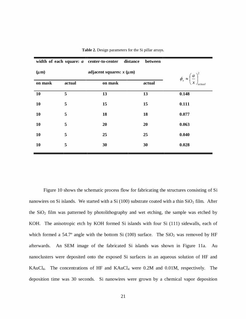
Table 2. Design parameters for the Si pillar arrays..................................................................... 21
Table 3. Results of WCA measurements on surfaces made by packing α-Fe2O3 particles with
different morphologies before and after ageing treatments. ......................................... 35

ix
LIST OF FIGURES
Figure 1. Superhydrophobic surfaces on lotus leaves. (a) Water droplets on the lotus leaf. (b)
Typical SEM images of the surface structures on the lotus leaf. ...................................1
Figure 2. Contact angle of a liquid on an ideally flat surface (Young's model). For water, if θflat <
90°, it is an intrinsically hydrophilic surface (a); if θflat > 90°, it is an intrinsically
hydrophobic surface (b). ..............................................................................................3
Figure 3. Relationship of cosθrough with cosθflat. The black solid and blue solid lines correspond
to the Wenzel state and the Cassie state, respectively. ..................................................5
Figure 4. Representative SEM images of superhydrophobic surfaces on rough hydrophobic
materials. (a) fractal AKD surface [13]; (b) laser-etched PDMS surface [14]; (c) PS-
PDMS/PS electrospun fiber mat [15]; (d) i-PP coatings obtained by phase separation
[16]; (e) PFPE-SS nanopillar film peeled from the p-AAO membrane [17]; (f) rough
poly(alkylpyrrole) film made by electrochemical synthesis [18]; (g) aligned ZnO
nanorods prepared by a two-step solution approach [19]; (h) TiO2 nanorod films [20]. 9
Figure 5. SEM images of superhydrophobic surfaces fabricated by coating hydrophilic micro-
and nano-structures with a hydrophobic coating. (a) silicon pillar arrays fabricated by
photolithography [21]; (b) silicon surfaces etched by a femtosecond laser [22]; (c)
silicon nanowires grown on Si/SiO2 substrate [23]; (d) etched aluminum surface [24];
(e) etched copper surface [24]; (f) etched zinc surface [24]. ....................................... 11
Figure 6. Relationship of roughcos with flatcos . The dotted and dashed lines correspond to the
metastable Cassie state when 90cos flat and the metastable Cassie state when
90cos flat , respectively. ....................................................................................... 16
Figure 7. Three cross-sectional profiles of water in contact with a solid indent consisting of
overhang structures. .................................................................................................. 17
Figure 8. Schematic process flow to fabricate the micrometer-sized Si pillars with overhangs at
the top edges. ............................................................................................................ 19
Figure 9. Design schematics for the Si pillar pattern. ................................................................ 20

x
Figure 10.Schematic process flow to fabricate the structures consisting of Si nanowires on Si
islands. ...................................................................................................................... 23
Figure 11.SEM images. (a) Si islands fabricated by etching a SiO2-masked Si(100) substrate in
KOH. (b) Si nanowires grown on the Si islands with Au clusters on the tips of the
nanowires. The scale bars are 5 m. ......................................................................... 23
Figure 12.Superhydrophobic surfaces consisting of Si pillars with overhangs at the top edges. (a)
SEM image of the Si pillars. (b) A close-up SEM image of (a). (c) An optical image
of a water droplet on the Si pillars during the contact angle measurement. (d) Static
water contact angles measured as a function of s . The solid line is plotted according
to the Cassie-Baxter relation (Eqn. 4). ....................................................................... 25
Figure 13.Superhydrophobic surfaces with hierarchical structures. (a) SEM image of Si
nanowire arrays grown on micrometer-sized Si islands. (b) A schematic cross-
sectional profile of (a). (c) SEM image of the surface of a Lotus leaf. (d) A schematic
cross-sectional profile of (c). The scale bars in (a) and (c) are 5 m. ......................... 26
Figure 14.Schematics of re-entrant surface curvatures for the electrospun fibers (A) and the
micro-hoodoos (B). The blue surface is wetted while the red surface remains
nonwetted when in contact with a liquid whose equilibrium contact angle (intrinsic
contact angle) is (< 90 ) [40]. ............................................................................... 28
Figure 15.Flower-like α-Fe2O3 particles. (a) An SEM image of a particle. (b) A TEM image of
two α-Fe2O3 particles. (c) TEM image taken at the edge of a plate. (d) XRD pattern of
the synthesized particles. ........................................................................................... 31
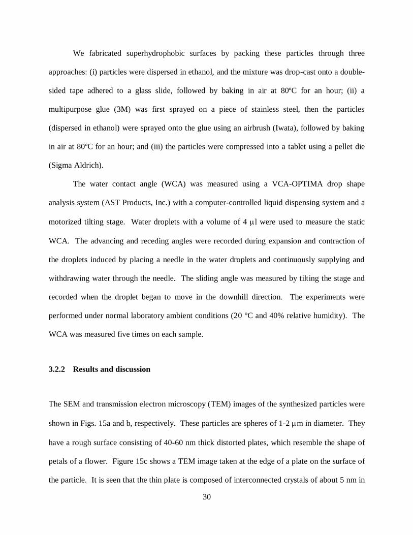
Figure 16.Superhydrophobic surfaces fabricated by packing the flower-like α-Fe2O3 particles. (a)
A typical SEM image of the surfaces. (b) Optical image of a water droplet on the
surface. Inset is an optical image of the water droplet during the WCA measurement.
(c) Schematic cross-sectional profile of water in contact with the flower-like particles.
(d) Schematic cross-sectional profile of water in contact with a solid indent consisting
of overhanging structures. ......................................................................................... 32
Figure 17.SEM images of (a) mechanically ground particles, (b) commercial micrometer-sized
particles, and (c) commercial nanometer-sized particles. Insets are the optical images
of the water droplet during the WCA measurement. .................................................. 34
Figure 18.Schematic of Au-assisted electroless etching ............................................................. 39
Figure 19.Porous silicon surface fabricated by Au-assisted electroless etching. (a) Top-view
SEM image. (b) Cross-sectional view SEM image. The inset is an optical image of a
water droplet on the surface. (c) Schematic cross-sectional profile of water in contact
with the porous silicon surface. ................................................................................. 40

xi
Figure 20.Schematic cross-sectional profile of liquid in contact with the porous silicon surface
consisting of overhang structures in the case of (a) flatoverhang and (b) flatoverhang .
.................................................................................................................................. 41
Figure 21.Static water contact angle measured on the porous Si as a function of the etching time.
.................................................................................................................................. 42
Figure 22.Water in contact with the porous Si with vertically aligned straight pores. (a)
Representative SEM image of the porous silicon with vertically aligned straight pores.
The inset is an optical image of a water droplet on the surface. (b) Schematic cross-
sectional profile of water in contact with the porous silicon surface, where
flatoverhang . ........................................................................................................... 43
Figure 23.Static contact angles of water, diethylene glycol, and hexadecane on flat silicon (Si),
porous silicon (PS), flat silicon coated with FTS (FTS-Si) and porous silicon coated
with FTS (FTS-PS).................................................................................................... 45
Figure 24.Schematic process for preparing the coatings. (a) Layer-by-layer assembly of 20 nm
silica (SiO2) nanoparticles and 60 sacrificial polystyrene (PS) nanoparticles. Adhesion
layers are deposited before the deposition of body layers. (b) The assembled
nanocomposite coating is treated by UVO and functionalized by FTS either directly
after the assembly or after removal of the sacrificial PS particles through calcination.
.................................................................................................................................. 51
Figure 25.SEM images of the coatings. (a) and (b) are SEM images of the coatings with 25
bilayers before and after removing the sacrificial polystyrene particles, respectively.
Labeled in (a) are a representative 60 nm polystyrene particle (labeled by ―1‖) and a
representative 20 nm silica particle (labeled by ―2‖). The polystyrene particles
disappear in (b) after calcination. The scale bars are 200 nm..................................... 53
Figure 26.Advancing and receding contact angles as a function of the number of the bilayers on
(a) the first set of coatings that are prepared without removing the sacrificial
polystyrene particles and (b) the second set of coatings that are prepared after
removing the sacrificial polystyrene particles. ........................................................... 54
Figure 27.Photographs of a coated glass slide with droplets of (a) water and (b) hexadecane to
demonstrate the superhydrophobicity, high oil-repellency, and transparency of the
coating. Insets in (a) and (b) are images taken during the contact angle measurement.
(c) Transmission spectrum of the glass slide before and after the coating process. The
glass slide is coated with 25 bilayers, and is calcinated and functionalized with FTS. 59
Figure 28.Probability of ice formation and the advancing and receding angles of water droplets
on each particle-polymer composite as a function of the particle size. ........................ 65
Figure 29.Optical images taken during the icing experiment, demonstrating the anti-icing
property of a superhydrophobic nanoparticle-polymer composite. Supercooled water
(-20 °C) was poured onto two Al plates. The right plate was untreated, while the left

xii
one was coated with a nanoparticle-polymer composite (with 50 nm particles). On the
right plate, ice formed instantly when the supercooled water impacted the plate. In
contrast, on the left, ice did not form when the supercooled water impacted the plate,
but built up from the bottom edge where the plate was in contact with an untreated Al
tray. ........................................................................................................................... 66
Figure 30.Representative electron microscopy images of particle-polymer composites. a,
Scanning electron microscopy (SEM) image of a particle-polymer composite made
with 20 nm silica particle. Scale bar, 1 µm. Inset, transmission electron microscopy
image. Scale bar, 50 nm. b, SEM image of a particle-polymer composite made with 50
nm silica particles. Scale bar, 1 µm. c, SEM image of a particle-polymer composite
made with 20 m silica particles. Scale bar, 100 µm................................................. 67
Figure 31.Heterogeneous nucleation on the surface of a superhydrophobic particle-polymer
composite. (a) Schematic cross-sectional profile of water in contact with a
superhydrophobic particle-nanoparticle composite. (b) Ratio (f) of the free-energy
barrier for nucleation around a spherical particle relative to that in the bulk versus the
relative particle radius ( / cR r ).................................................................................... 68
Figure 32.Test of anti-icing properties in naturally occurring ―freezing rain‖. (a) Untreated side
of an aluminum plate after the natural occurrence of ―freezing rain‖. (b) Treated side
of the aluminum plate coated with a superhydrophobic composite after the ―freezing
rain‖. (c) Satellite dish antenna after the freezing rain. The left side is untreated and is
completely covered by ice, while the right side is coated with the superhydrophobic
coating and has no ice. (d) Close-up view of the area labeled by a red square in (c),
showing the boundary between the coated (no ice) and uncoated area (ice) on the
satellite dish antenna. ................................................................................................ 70
Figure 33.Schematic diagrams of boundary conditions. (a) No-slip condition. (b) Slip condition.
.................................................................................................................................. 74
Figure 34.Schematic diagram of laminar flows between two infinite parallel plates with
superhydrophobic surfaces. Water is in contact with a composite surface of solid and
air. The flow direction is parallel to the x-axis. ......................................................... 77
Figure 35.Experimental setup. (a) and (b) are schematic front and side views of the channel. (c)
An SEM image of superhydrophobic nanoparticle-polymer composite coating. (d)
Optical images of water droplets on the superhydrophobic coating. ........................... 79
Figure 36.Simulation results. (a) and (b) are snapshots of the velocity profiles generated by
simulating laminar flows (with Re = 10) in two types of channels formed between
smooth solid plates and superhydrophobic plates, respectively. (c) Pressure gradient in
two types of channels as a function of Re. The solid line is the analytical solution. (d)
Slip length and the relative reduction of the friction factor Rf (inset) as a function of
Re. ............................................................................................................................. 81

xiii
Figure 37.Data obtained from experimental results: (a) pressure drop measurements as a function
of Re; (b) the influence of Re on the slip length as well as the drag reduction (inset). . 83
xiv
ACKNOWLEDGEMENTS
First I would like to express my sincere appreciation to my advisor, Prof. Di Gao, for his
constant guidance, support, and discussion throughout my PhD research work. He is a
wonderful person and a great mentor. It has been my great pleasure working in his group.
I would also like to thank my committee members, Prof. William J. Federspiel, Prof.
Sachin S. Velankar, and Prof. Sung Kwon Cho, for your time and constructive suggestion for
this thesis.
Furthermore, I would like to thank all my group members, Jiamin Wu, Ashish Yeri,
Umang Desai, Dr. Lizeng Gao, Dr. Chengkun Xu, and Dr. Anmin Cao, for your great help in my
research. Also,we had lots of fun in the lab, which made the research work more productive
and enjoyable.
Finally, I would like to dedicate my thesis to my parents, my lovely daughter Iris, and my
wife Jianxia Liu. Without her support, encouragement, and care, I really cannot imagine what I
could be right now. She has turned my life into a totally different and positive way, and let me
have a great journey during my PhD process or even all my life.

1
1.0 INTRODUCTION
1.1 SUPERHYDROPHOBIC SURFACES IN NATURE
Superhydrophobic surfaces are often found in nature, such as on plant leaves [1-3], insect legs [4]
and wings [5]. Water on these surfaces forms small beads with a high contact angle in excess of
150º and drips off rapidly when the surfaces are slightly inclined, while taking away powder-like
contaminant. This interesting phenomenon has stimulated extensive research to make artificial
superhydrophobic surfaces and to use them for a variety of applications.
Figure 1. Superhydrophobic surfaces on lotus leaves. (a) Water droplets on the lotus leaf. (b) Typical SEM images
of the surface structures on the lotus leaf.

2
The concept of superhydrophobic surfaces is originally drawn from the inspiration of
lotus leaves in nature. Therefore, the very high water repellency (superhydrophobicity) and the
self-cleaning properties exhibited by the lotus leaf have been referred to as ―lotus effect‖, which
has been attributed to a combined effect of the hydrophobicity induced by the epicuticular wax
and the surface roughness resulted from the hierarchical structures on the leaf (Fig. 1).
1.2 WETTING ON SURFACES
1.2.1 Wetting on flat surfaces
When a liquid droplet is deposited on a chemically homogenous and physically flat (or smooth)
solid surface (Fig. 2), the surface wettability is mainly determined by the surface chemical
composition. The liquid contact angle on the flat surface (or the intrinsic water contact
angle, flatθ ) can be correlated to three interfacial free energies, i.e., free energies at the solid-air
( SVγ ), solid-liquid ( SLγ ) and liquid-air ( LVγ ) interfaces, by the Young‘s equation:
LV
SLSVflat
cos , (1)
where SLγ can be estimated by [6]
LVSVLVSVSL 2 . (2)

3
Figure 2. Contact angle of a liquid on an ideally flat surface (Young's model). For water, if θflat < 90°, it is an
intrinsically hydrophilic surface (a); if θflat > 90°, it is an intrinsically hydrophobic surface (b).
According to Eqns. (1) and (2), the surface hydrophobicity increases with decreasing the
surface free energy of the solid-air interface ( SVγ ). When θflat is smaller than 90°, the solid
surface is considered intrinsically hydrophilic; when θflat is greater than 90°, the solid surface is
considered intrinsically hydrophobic. The reported lowest surface free energy of the solid-air
interface is possessed by the trifluoromethyl group (CF3)-terminated surface (~ 6 mN/m) [7],
with a θflat of ~ 120º, which is almost the highest water contact angle that can be obtained on a
flat surface. Further increase of the hydrophobicity requires manipulation of the surface
topography.
1.2.2 Wetting on rough surfaces
The effect of surface roughness on wettability was first discussed by Wenzel in 1936 [8] and
then by Cassie and Baxter in 1944 [9]. Wenzel suggested that the effective surface area
increases as the surface becomes rough, and hence water will tend to spread more on a rough
4
hydrophilic substrate to develop more solid-liquid contact, while spread less on a rough
hydrophobic substrate to decrease the contact area to solid, both of which are thermodynamically
more favorable. A key assumption of this conclusion is that water is in complete contact with
the solid surface, which is called Wenzel state (Fig. 3a). The relationship between the apparent
contact angle on a rough surface ( roughθ ) and its intrinsic contact angle ( flatθ ) has been described
by the Wenzel equation:
flatrough r coscos , (3)
where r is the roughness factor, defined as the ratio of the actual surface area to its horizontal
projection. Since r is always greater than 1 for a rough surface, this equation predicts that
if o90flatθ , flatroughθ , and if o90flatθ , flatroughθ . Therefore, in the Wenzel state, surface
roughness will make intrinsically hydrophobic surfaces more hydrophobic and intrinsically
hydrophilic surfaces more hydrophilic.
However, as the surface roughness or the surface hydrophobicity increases, it becomes
unlikely for water to completely follow the surface topography of a hydrophobic substrate so as
to have a complete contact with the solid surface, since the system is in a higher energy state
when the hydrophobic substrate is in complete contact with water than when it is only in partial
contact with water. Instead, air may be trapped between water and the surface texture. As a
result, water is in contact with a composite surface of solid and air, and forms droplets (known as
fakir droplets). Such state is called Cassie State (Fig. 3b). The apparent contact angle in this
case has been described by the Cassie-Baxter equation
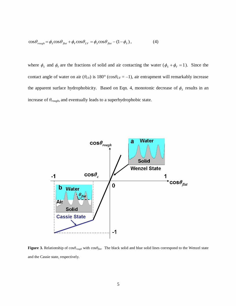
5
)1(coscoscoscos SflatSLVVflatSrough , (4)
where S and V are the fractions of solid and air contacting the water ( 1 VS ). Since the
contact angle of water on air (θLV) is 180° (cosθLV = –1), air entrapment will remarkably increase
the apparent surface hydrophobicity. Based on Eqn. 4, monotonic decrease of S results in an
increase of θrough, and eventually leads to a superhydrophobic state.
Figure 3. Relationship of cosθrough with cosθflat. The black solid and blue solid lines correspond to the Wenzel state
and the Cassie state, respectively.

6
For a system where water is in contact with a rough solid surface, one of the two states
(Wenzel state or Cassie state) may exist. The relationship between cosθrough and cosθflat for these
two states is plotted in Figure 3, according to Eqns. (3) and (4), as previously demonstrated [10].
The two lines corresponding to the two states intersect at one critical angle θc
S
Sc
r
1cos . (5)
It has been proved that the energy of the system decreases monotonically when cosθrough
increases [11]. Therefore, when water contacts a solid surface with θflat < θc, the Wenzel state is
thermodynamically more favorable (with smaller θrough and greater cosθrough than those in the
Cassie state) and hence should be preferred by the system from a thermodynamic point of view;
when water contacts a solid surface with θflat > θc , the Cassie state is thermodynamically more
favorable. It should be noted that, according to Eqn. (5), θc is always greater than 90°, since
1S and 1r .
1.2.3 Contact angle hysteresis
In addition to the contact angle measured in a static manner, another parameter, contact angle
hysteresis, is also important for characterizing the surface wettability. The contact angle
hysteresis is the difference between the advancing and receding contact angles typically
measured during expansion and contraction of the droplets induced by placing a needle in the
water droplets and continuously supplying and withdrawing water through the needle. The
advancing contact angle A is recorded when the liquid volume reaches maximum before the

7
liquid-solid interfacial area starts to increase; the receding contact angle R is recorded when the
liquid volume reaches minimum before the interfacial area starts to decrease. Sometimes, sliding
angle, which is defined as the minimum angle that the substrate needs to be tilted before a
droplet starts to roll off, is also used to characterize the wettability of a surface. The relationship
between the contact angle hysteresis and the sliding angle can be described by the following
equation [12]:
)cos(cos/)(sin ARlvwmg , (6)
where is the sliding angle, g is the acceleration due to gravity, m is the mass of the droplet, and
w is the diameter of the wetting area. From Eqn. 6, it can be seen that the sliding angle depends
on the mass or the size of the droplet and for the same sized droplet, small contact angle
hysteresis will lead to a small sliding angle. Therefore, sliding angle can be used to compare the
wettability of two surfaces only when the same sized droplet is used, and the contact angle
hysteresis is a better parameter for the purpose of characterizing the surface wettability. Typical
superhydrophobic surfaces should have a static water contact angle of greater than 150º and
contact angle hysteresis of smaller than 10º.
1.3 CONVENTIONAL FABRICATION OF SUPERHYDROPHOBIC SURFACES
To date, a wide variety of physical and chemical methods have been explored to fabricate
superhydrophobic surfaces through one of the following two approaches: (i) creating a rough
surface on a hydrophobic material or (ii) modifying a rough surface with a hydrophobic coating.

8
1.3.1 Creating a rough surface on a hydrophobic material
In this approach, hydrophobic polymers are typically used as the substrate to obtain
superhydrophobicity. By making the surfaces of the polymer materials rough, the
superhydrophobic behavior can be readily observed. Onda et al. prepared a super-water-
repellent fractal surface by solidifying the melted alkylketene dimmer (AKD, a kind of wax) (Fig.
4a) [13]. It has been demonstrated that the contact angle of a liquid droplet placed on a fractal
surface can be expressed as a function of the fractal dimension, the range of fractal behavior, and
the contacting ratio of the surface. Jin et al. reported a laser etching method to make
superhydrophobic polydimethylsiloxane (PDMS) surface, which contains micro-, submicro- and
nano-composite structures (Fig. 4b) [14]. The water contact angle for the etched PDMS surface
is higher than 160° and sliding angle is lower than 5°. Ma et al. made a superhydrophobic
membrane in the form of a nonwoven fiber mat by electrospinning a PS-PDMS block polymer
blended with PS homopolymer (Fig. 4c) [15]. The superhydrophobicity is attributed to the
combined effect of surface enrichment in siloxane and surface roughness of the electrospun mat
itself. Phase separation has also been utilized to make superhydrophobic surfaces. Erbil et al.
prepared a superhydrophobic gel-like porous popypropylene coating by casting the polymer
solution, where nonsolvents were used in conjunction with p-xylene solvent as a polymer
precipitator to increase the extent of polymer phase separation (Fig. 4d) [16]. Zhang et al.
demonstrated the fabrication of 2-D arrays of nanopillars made from perfluoropolyether
derivatives using a porous anodic aluminum oxide membrane as a template (Fig. 4e). Both
nanopillars on a flat surface and on a lotus-leaf-like topology exhibit superhydrophobcity, low
contact angle hysteresis, and self-cleaning properties [17]. Yan et al. fabricated
superhydrophobic poly(alkylpyrrole) films by a electrochemical synthesis method (Fig. 4f). The

9
film surface consists of thousands of ―needle‖-like microstructures in a perpendicular alignment
[18].
Figure 4. Representative SEM images of superhydrophobic surfaces on rough hydrophobic materials. (a) fractal
AKD surface [13]; (b) laser-etched PDMS surface [14]; (c) PS-PDMS/PS electrospun fiber mat [15]; (d) i-PP
coatings obtained by phase separation [16]; (e) PFPE-SS nanopillar film peeled from the p-AAO membrane [17]; (f)
rough poly(alkylpyrrole) film made by electrochemical synthesis [18]; (g) aligned ZnO nanorods prepared by a two-
step solution approach [19]; (h) TiO2 nanorod films [20].
Furthermore, certain inorganic materials have also been employed in the fabrication of
superhydrophobic surfaces. Feng et al. synthesized aligned ZnO nanorods via a two-step
solution approach (Fig. 4g). The ZnO nanorods films exhibit superhydrophobicity which is due
to the surface roughness and the low surface energy of the (001) plane of the nanorods exposed
on the film surface. More interestingly, reversible superhydrophobicity to superhydrophilicity
transition was observed and well controlled on the ZnO nanorod films by alternation of UV
illumination and dark storage [19]. A similar result was also obtained on the TiO2 nanorod films
from their following work (Fig. 4h) [20].
10
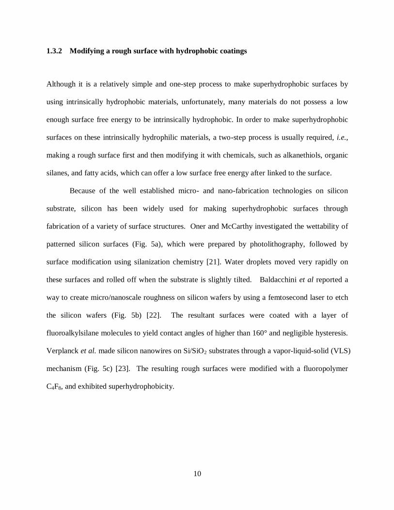
1.3.2 Modifying a rough surface with hydrophobic coatings
Although it is a relatively simple and one-step process to make superhydrophobic surfaces by
using intrinsically hydrophobic materials, unfortunately, many materials do not possess a low
enough surface free energy to be intrinsically hydrophobic. In order to make superhydrophobic
surfaces on these intrinsically hydrophilic materials, a two-step process is usually required, i.e.,
making a rough surface first and then modifying it with chemicals, such as alkanethiols, organic
silanes, and fatty acids, which can offer a low surface free energy after linked to the surface.
Because of the well established micro- and nano-fabrication technologies on silicon
substrate, silicon has been widely used for making superhydrophobic surfaces through
fabrication of a variety of surface structures. Oner and McCarthy investigated the wettability of
patterned silicon surfaces (Fig. 5a), which were prepared by photolithography, followed by
surface modification using silanization chemistry [21]. Water droplets moved very rapidly on
these surfaces and rolled off when the substrate is slightly tilted. Baldacchini et al reported a
way to create micro/nanoscale roughness on silicon wafers by using a femtosecond laser to etch
the silicon wafers (Fig. 5b) [22]. The resultant surfaces were coated with a layer of
fluoroalkylsilane molecules to yield contact angles of higher than 160° and negligible hysteresis.
Verplanck et al. made silicon nanowires on Si/SiO2 substrates through a vapor-liquid-solid (VLS)
mechanism (Fig. 5c) [23]. The resulting rough surfaces were modified with a fluoropolymer
C4F8, and exhibited superhydrophobicity.

11
Figure 5. SEM images of superhydrophobic surfaces fabricated by coating hydrophilic micro- and nano-structures
with a hydrophobic coating. (a) silicon pillar arrays fabricated by photolithography [21]; (b) silicon surfaces etched
by a femtosecond laser [22]; (c) silicon nanowires grown on Si/SiO2 substrate [23]; (d) etched aluminum surface
[24]; (e) etched copper surface [24]; (f) etched zinc surface [24].
Metal surfaces can be made superhydrophobic by first etching the surfaces to obtain
roughness in both micrometer and nanometer scales and then modifying the roughened surfaces
with a hydrophobic coating. Qian et al. have made superhydrophobic surfaces on aluminum,
copper, and zinc polycrystalline substrates by first using chemical etching methods and then
coating the substrates with a fluoroalkysilane [24]. The key to the etching technique is the use of
a dislocation etchant that preferentially dissolves the dislocation sites in the grains. The etched
metallic surfaces, after modified with the fluoroalkylsilane, exhibited superhydrophobic
properties with water contact angles of larger than 150°, as well as sliding angles of less than 10°.

12
Electrochemical methods have also been employed to make superhydrophobic surfaces on metal
substrates. Zhang et al. described the use of polyelectrolyte multilayers in electrochemical
deposition to adjust the morphology of gold clusters for fabrication of superhydrophobic surfaces
[25]. They also fabricated a branchlike structure of silver aggregates by electrodeposition
techniques. After modification with a self-assembled monolayer of n-dodecanethiol, the surface
became superhydrophobic [26].
1.4 CHALLENGES
As discussed above, both of the current approaches for fabrication of superhydrophobic surfaces
require a solid surface with a low enough free energy and hence an intrinsic water contact angle
( flat ) of greater than 90° to further enhance the hydrophobicity by tailoring the surface
roughness. Processes for obtaining a low surface free energy typically involve modifying the
surfaces with organic chemical coatings. However, the hydrophobicity of chemically treated
surfaces deteriorates over time, which brings major problems to the artificial superhydrophobic
surfaces—aging and decay.
Another challenge to the self-cleaning property of superhydrophobic surfaces is oil
contamination―these surfaces repel water but not oil. Following Eqns. (1) and (2), to achieve a
flat of greater than 90°, a SVγ of less than ~ 20 mN/m is needed for water (with a LVγ of ~72
mN/m), and a SVγ of less than ~ 6 mN/m is needed for most alkanes with a LVγ of 20-30 mN/m.
If a flat of greater than 90° is indeed needed to increase the contact angle by roughening the
surface, then very few materials can be used to make super oil-repellent surfaces. For example,
13
Teflon is known to possess a low SVγ (~ 18.5 mN/m) among most commonly used materials, but
it still does not satisfy the requirement ( SVγ needs to be less than ~ 6 mN/m) to make it super oil-
repellent (or superoleophobic). (CF3)-terminated surfaces (with a SVγ of ~ 6 mN/m), in principle,
can barely satisfy this requirement. However, to experimentally obtain (CF3)-terminated
surfaces with such low s has been proven challenging. Therefore, although super oil-repellent
surfaces have been reported, the oil contact angles in the literature are often reported using oils
with a relatively high LVγ (> 30 mN/m) such as polyols, esters, arenes, and/or their mixtures [27,
28]. As a matter of fact, surfaces that possess a contact angle of greater than 150° for alkanes
(such as hexadecane) with LVγ between 20 and 30 mN/m have rarely been reported before our
work. The surface tension values for some common test liquids are listed in Table 1.
A question of significant interest is whether one is able to produce a superhydrophobic
surface using materials with a flat of less than 90° because this implies the possibility of making
intrinsically hydrophilic materials superhydrophobic or even making intrinsically oleophilic
materials superoleophobic. As a matter of fact, nature has provided a positive answer to this
question by the fact that some leaves with an absence of hydrophobic waxes are also
superhydrophobic [29]. Recent research has also found that the wax on lotus leaves has a flat of
~74°, in contrast to the expected value of greater than 90° [30]. One focus of this dissertation is
to elucidate the fundamental mechanisms underlying this interesting surface phenomenon, and to
develop design principles and fabrication methods for making superhydrophobic surfaces on
intrinsically hydrophilic materials as well as for making superoleophobic surfaces on
intrinsically oleophilic materials.
14
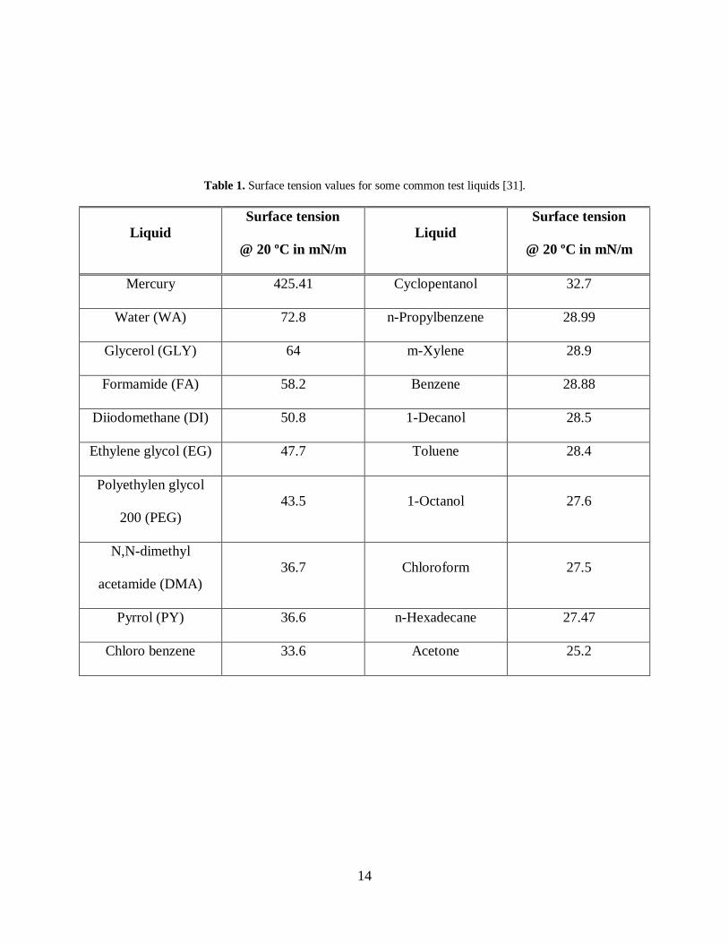
Table 1. Surface tension values for some common test liquids [31].
Liquid
Surface tension
@ 20 ºC in mN/m
Liquid
Surface tension
@ 20 ºC in mN/m
Mercury 425.41 Cyclopentanol 32.7
Water (WA) 72.8 n-Propylbenzene 28.99
Glycerol (GLY) 64 m-Xylene 28.9
Formamide (FA) 58.2 Benzene 28.88
Diiodomethane (DI) 50.8 1-Decanol 28.5
Ethylene glycol (EG) 47.7 Toluene 28.4
Polyethylen glycol
200 (PEG)
43.5 1-Octanol 27.6
N,N-dimethyl
acetamide (DMA)
36.7 Chloroform 27.5
Pyrrol (PY) 36.6 n-Hexadecane 27.47
Chloro benzene 33.6 Acetone 25.2

15
2.0 METASTBALE CASSIE STATE
The presence and potential importance of the metastable Cassie state have been discussed
previously [32-35], where Fakir droplets in the Cassie state were observed on the surfaces
consisting of high density textures when cflat o90 . Such a metastable Cassie state is
represented by the dotted line as an extension of the solid line representing the Cassie state in
Figure 6 [10]. A question that remains is if the metastable Cassie state may also exist when
o90flat (i.e., 0cos flat ), as represented by the dashed lines in the fourth quadrant of Figure
6. If possible, this suggests that one can take advantage of the metastable Cassie state to make
superhydrophobic surfaces on intrinsically hydrophilic materials or even superoleophobic
surfaces on intrinsically oleophilic materials. Although, as early as 2000, Herminghaus has
already conceptually predicated the possibility of the existence of metastable Cassie state when
o90flat which may arise from certain special surface topography such as overhang structures
[36], it has not been experimentally demonstrated prior to our work.
A necessary condition for observing the metastable Cassie state is the existence of an
energy barrier that separates the Wenzel state and the Cassie state. In our design principle, this
energy barrier may be provided by a capillary force that prevents liquids from entering the
indents present on the surface. In the case of o90flat , overhang structures are needed to
provide positions for the liquid-solid contact line to suspend liquids above the bottom surface.

16
Figure 6. Relationship of roughcos with flatcos . The dotted and dashed lines correspond to the metastable
Cassie state when 90cos flat and the metastable Cassie state when 90cos flat , respectively.
Figure 7 shows three possible cross-sectional profiles for water in contact with a solid indent
consisting of overhangs. A critical parameter for these different profiles is the angle ( overhang )
formed between the sidewalls of the indent and the horizontal line. When overhang is greater than
flat of the sidewall surface (Fig. 7a), the water-air interface (meniscus) inside the indent is
concave when viewed from the water side. The net force generated by the meniscus (Fs) is
toward the inside of the indent, causing water to enter the indent and have complete contact with
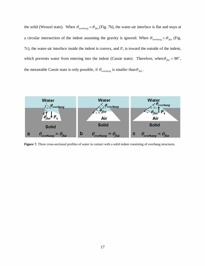
17
the solid (Wenzel state). When flatoverhang (Fig. 7b), the water-air interface is flat and stays at
a circular intersection of the indent assuming the gravity is ignored. When flatoverhang (Fig.
7c), the water-air interface inside the indent is convex, and Fs is toward the outside of the indent,
which prevents water from entering into the indent (Cassie state). Therefore, when o90flat ,
the metastable Cassie state is only possible, if overhang is smaller than flat .
Figure 7. Three cross-sectional profiles of water in contact with a solid indent consisting of overhang structures.

18
3.0 FABRICATION OF SUPERHYDROPHOBIC AND SUPEROLEOPHOBIC
SURFACES ON INTRINSICALLY HYDROPHILIC AND OLEOPHILIC MATERIALS
3.1 SUPERHYDROPHOBIC SURFACES ON INTRINSICALLY HYDROPHILIC
SILICON PILLARS
In this section, we report the design and fabrication of micro-textures for inducing a
superhydrophobic behavior on hydrogen (H)-terminated silicon surfaces with a flat of ~74º. The
micro-textures consist of overhangs with well-defined geometries fabricated by micro- and nano-
fabrication technologies, which provide positions to support water and prevent water from
entering the indents between the textures. As a result, water is in contact with a composite
surface of solid and air, which induces the observed macroscopic superhydrophobic behavior.
3.1.1 Experimental design and methodology
We fabricate micro-textures consisting of overhang structures with well-defined geometries in
both micrometer and nanometer scales. Figure 8 schematically shows the process flow to
fabricate the micrometer-sized Si pillars with overhangs at the top edges. We started with Si
(100) wafer coated with a 0.5 m thermally-grown silicon dioxide (SiO2) thin film. The SiO2
film was patterned by photolithography, followed by wet etching in HF aqueous solution. A

19
Bosch deep reactive ion etching (DRIE) process using inductively coupled plasma was employed
to etch the SiO2-masked Si substrate, which formed arrays of Si pillars with vertical sidewalls.
By aligning the square patterns of the Si pillars with the Si (100) wafer flat, the Si (110) surfaces
were exposed on the four sidewalls of each pillar after this process. The exposed Si (110)
sidewalls were then etched in a potassium hydroxide (KOH) aqueous solution (30% by weight)
at 75 ºC for 3 minutes. Etching of Si by KOH was anisotropic, which exposed (111) surfaces on
the sidewalls of the Si pillars. The exposed Si (111) surface underneath the top SiO2 mask
formed overhanging sidewalls at an angle (overhang) of 54.7º to the top Si (100) surfaces. The
SiO2 mask was removed by HF afterwards, leaving a H-terminated Si surface.
Figure 8. Schematic process flow to fabricate the micrometer-sized Si pillars with overhangs at the top edges.
Figure 9 schematically shows the top view of the design for the Si pillars. The pattern is
a two-dimensional array of squares, which is 1 cm wide and 1 cm long. The critical parameters

20
are the width of each square (a) and the center-to-center distance between adjacent squares (x).
In the mask design for photolithography, a is fixed at 10 m, and x is varied from 13 to 30 m.
When the pattern of the photoresist was transferred to the underneath SiO2 layer, the size of the
squares decreased due to the isotropic etching of the SiO2 by HF aqueous solution. The actual
size of the squares was determined from the scanning electron microscopy (SEM) images taken
afterwards. The center-to-center distance of the squares remained unchanged during the pattern
transfer. These parameters and the corresponding s (the area fraction of the solid surface in
contact with water) are listed in Table 2.
Figure 9. Design schematics for the Si pillar pattern.
21
Table 2. Design parameters for the Si pillar arrays.
width of each square: a
(m)
center-to-center distance between
adjacent squares: x (m) 2
actual
sx
a
on mask actual on mask actual
10 5 13 13 0.148
10 5 15 15 0.111
10 5 18 18 0.077
10 5 20 20 0.063
10 5 25 25 0.040
10 5 30 30 0.028
Figure 10 shows the schematic process flow for fabricating the structures consisting of Si
nanowires on Si islands. We started with a Si (100) substrate coated with a thin SiO2 film. After
the SiO2 film was patterned by photolithography and wet etching, the sample was etched by
KOH. The anisotropic etch by KOH formed Si islands with four Si (111) sidewalls, each of
which formed a 54.7º angle with the bottom Si (100) surface. The SiO2 was removed by HF
afterwards. An SEM image of the fabricated Si islands was shown in Figure 11a. Au
nanoclusters were deposited onto the exposed Si surfaces in an aqueous solution of HF and
KAuCl4. The concentrations of HF and KAuCl4 were 0.2M and 0.01M, respectively. The
deposition time was 30 seconds. Si nanowires were grown by a chemical vapor deposition
22
process [37, 38]. Silicon tetrachloride (SiCl4, Aldrich, 99.99%) was used as the precursor.
Hydrogen gas (10% in argon by volume) was used as the carrier gas. The nanowires were grown
at 850 ºC via a vapor-liquid-solid mechanism [37]. The Si nanowires synthesized by this method
had a strong preferred growth direction along the <111> axis, and therefore were vertical to the
exposed Si (111) sidewalls. An SEM image taken after the growth of Si nanowires was shown in
Figure 11b. The Au clusters at the tips of the nanowires were removed by an aqueous solution of
HCl and HNO3 (aqua regia), followed by treatment with HF. The sample was thoroughly rinsed
in deionized water and dried in air before the contact angle was measured.
All the SEM images were taken by a Philips XL-30 field emission SEM setup. The Lotus
leaf was purchased from a local Chinese grocery store. The leaf was dried and coated with a ~3
nm thin gold film by sputtering before the SEM images were taken.
The static water contact angles were measured according to the sessile droplet method
using a drop shape analysis system (AST Products, Inc.) with a computer-controlled liquid
dispensing system. Water droplets with a volume of 8 l were used. The experiment was
performed under normal laboratory ambient conditions, 20 °C and 40% relative humidity. The
contact angles were measured five times on each sample.

23
Figure 10. Schematic process flow to fabricate the structures consisting of Si nanowires on Si islands.
Figure 11. SEM images. (a) Si islands fabricated by etching a SiO2-masked Si(100) substrate in KOH. (b) Si
nanowires grown on the Si islands with Au clusters on the tips of the nanowires. The scale bars are 5 m.
24
3.1.2 Results and discussion
The micrometer-sized Si pillars with overhangs at the top edges fabricated by micromachining
techniques are shown in Figs. 12a and b. The top surfaces of the Si pillars were 5 m × 5 m
squares, and 15 m above the bottom surfaces. The overhanging Si (111) sidewalls formed an
angle (overhang) of 54.7° with the top Si (100) surfaces. We fabricated a series of such Si pillar
arrays by varying the center-to-center distance (x) between adjacent pillars from 13 to 50 m.
The flat of H-terminated Si surface was measured to be 74 ± 3°, which was consistent with
previous reports [39]. Therefore, these Si pillars provide us with an ideal system to study the
wettability of surfaces consisting of overhanging structures with overhang < flat <90º.
The static water contact angles of these surfaces were measured (Fig. 12c), and plotted as
a function of s in Figure 12d. It was observed that rough increased from ~139º to ~162º as s
decreased from ~ 0.15 to ~ 0.04 until x reached ~ 30 m. When x was further increased, the
measured contact angles were scattered and unrepeatable, owing to the tendency of drops to fall
in the texture for such large gaps. When x was less than 30 m, the relationship between rough
and s agrees well with the Cassie-Baxter equation.
The fabricated surfaces with overhang structures by growing Si nanowires on
micromachined Si islands are shown in Figure 13a. The top surfaces of the Si islands were 5 m
× 5 m squares, with a 15 m center-to-center distance. The height of the islands was ~ 8 m.
The Si (111) sidewall of the islands formed a 54.7º angle with the bottom Si (100) surface. The
Si nanowires were ~ 3 m long with varied width ranging from 100 to 500 nm. The Si
nanowires grown vertically on the sidewalls of two adjacent Si islands faced each other, and
formed an overhanging structure with a overhang of 35.3º (Fig. 13b). The hierarchical structures

25
consisting of Si nanowires on Si islands provide another model system that satisfies the condition
of 90flatoverhang . The static water contact angle on the surface shown in Figure 13a was
measured to be ~ 160º.
Figure 12. Superhydrophobic surfaces consisting of Si pillars with overhangs at the top edges. (a) SEM image of
the Si pillars. (b) A close-up SEM image of (a). (c) An optical image of a water droplet on the Si pillars during the
contact angle measurement. (d) Static water contact angles measured as a function of s . The solid line is plotted
according to the Cassie-Baxter relation (Eqn. 4).

26
Figure 13. Superhydrophobic surfaces with hierarchical structures. (a) SEM image of Si nanowire arrays grown on
micrometer-sized Si islands. (b) A schematic cross-sectional profile of (a). (c) SEM image of the surface of a Lotus
leaf. (d) A schematic cross-sectional profile of (c). The scale bars in (a) and (c) are 5 m.
Superhydrophobicity has been observed on plant leaves where hydrophobic wax is absent
[29]. Recent experiments have also found that flat of the wax on the superhydrophobic surfaces
of Lotus leaves is approximately 74º, which is in contrary to the expected values of greater than
90º [30]. These observations cannot be understood by the previous explanation of the ―Lotus
effect‖, i.e., a wax-induced hydrophobicity ( 90flat ) enhanced by the surface roughness. The
results obtained in our experiments provide a plausible explanation to these phenomena. The
27
hierarchical structures on the surface of Lotus leaves consist of microscale bumps and nanoscale
hair-like protrusions (Fig. 13c). They form a similar surface topography (Fig. 13d) as the
surfaces constructed using Si nanowires and Si islands. The flat of the carnauba wax on the
surface of Lotus leaves is approximately 74°, which is also similar to the flat of the H-
terminated Si surface. Therefore, the superhydrophobicity of these Lotus leaves may be induced
by the same mechanism that has been suggested to explain the superhydrophobicity of the
hierarchical Si nanowire structures – the overhanging structures formed by the nanometer-sized
protrusions cause water to contact a composite surface of solid and air in a metastable Cassie
state, resulting in an apparent superhydrophobicity on surfaces with a flat of less than 90º.
Following the similar principle, Tuteja et al. demonstrated the possibility of designing
superoleophobic surfaces using intrinsically oleophilic materials with ―re-entrant surface
curvatures‖ (Fig. 14) [40]. The balance between the external pressure and the capillary force
was used to evaluate the robustness of the metastable Cassie state, where the characteristic
capillary rise height can be calculated fromgD
cosh lv
2 , which is inversely proportional to the
cavity size D. It was demonstrated that the presence of special topographic structures (e.g., re-
entrant curvature or overhangs) is not a sufficient condition for developing highly nonwetting
surfaces, because the metastable Cassie state may be inaccessible in practice if the capillary force
that prevents the liquid from entering the air pocket can be easily overcome, in which case the
Cassie state transits into the Wenzel state. This analysis may help us understand our
experimental result that the superhydrophobic behavior becomes unstable when x in our silicon
pillar design is beyond ~30 μm (Fig. 12).

28
Figure 14. Schematics of re-entrant surface curvatures for the electrospun fibers (A) and the micro-hoodoos (B).
The blue surface is wetted while the red surface remains nonwetted when in contact with a liquid whose equilibrium
contact angle (intrinsic contact angle) is (< 90 ) [40].
3.1.3 Conclusion
In summary, we have fabricated micro-textures consisting of overhanging structures of Si with
well-defined geometries in both micrometer and nanometer scales. Although the intrinsic water
contact angle of the H-terminated Si surface is about 74°, the constructed surfaces induce
superhydrophobic behavior. Certainly, problems such as the quantitative evaluation of the
stability of the metastable Cassie state, the hydraulic pressure required to wet the surfaces
fabricated in our work, and the transition between the Cassie and the Wenzel states in terms of
contact angle hysteresis still need to be studied further. Nonetheless, it is expected that this work
could provide additional insight into the interesting superhydrophobic phenomena found in
nature and that the principle could be applied to make intrinsically hydrophilic materials
superhydrophobic by tailoring the surface topography.

29
3.2 FABRICATION OF NON-AGING SUPERHYDROPHOBIC SURFACES BY
PACKING FLOWER-LIKE HEMATITE PARTICLES
In this section, we report the fabrication of superhydrophobic surfaces by packing flower-like
particles of hematite (α-Fe2O3), an intrinsically hydrophilic material. These superhydrophobic
surfaces do not age even in extremely oxidative environments—they are able to retain the
superhydrophobicity after being stored in ambient laboratory air for 4 months, heated to 800ºC in
air for 10 hours, and exposed to ultraviolet ozone for 10 hours.
3.2.1 Experimental design and methodology
The flower-like α-Fe2O3 particles were synthesized by using an ethylene glycol (EG)-mediated
reaction. The synthesis process was adopted from Zhong et al. [41] with the following
modifications: (i) the surfactant was removed from the previously used reaction system, and (ii)
iron nitrate [Fe(NO3)3] was used to replace the previously used iron chloride. In a typical
synthesis process, 0.7 g Fe(NO3)3 (Fisher Scientific) and 0.7 g urea (CO(NH2)2, Sigmar-Aldrich)
were added into 60 mL ethylene glycol (C2H6O2, J.T. Baker) to form a cloudy mixture. The
mixture was then stirred with a magnetic stirrer bar and heated to 170ºC. The cloudy mixture
turned clear in 10 min and became opaque again after 20 min, indicating the formation of iron
oxide precursor. The products were collected by centrifugation–redispersion cycles with
alcohol. The collected products were then calcined in air at 450ºC for 3 hours in a tube furnace
(Lindberg) to obtain α-Fe2O3 particles. The α-Fe2O3 particles were characterized by X-ray
diffractometry (XRD, Philips X‘pert), transmission electron microscopy (TEM, JEOL 2000FX),
and scanning electron microscopy (SEM, Philips XL-30).
30
We fabricated superhydrophobic surfaces by packing these particles through three
approaches: (i) particles were dispersed in ethanol, and the mixture was drop-cast onto a double-
sided tape adhered to a glass slide, followed by baking in air at 80ºC for an hour; (ii) a
multipurpose glue (3M) was first sprayed on a piece of stainless steel, then the particles
(dispersed in ethanol) were sprayed onto the glue using an airbrush (Iwata), followed by baking
in air at 80ºC for an hour; and (iii) the particles were compressed into a tablet using a pellet die
(Sigma Aldrich).
The water contact angle (WCA) was measured using a VCA-OPTIMA drop shape
analysis system (AST Products, Inc.) with a computer-controlled liquid dispensing system and a
motorized tilting stage. Water droplets with a volume of 4 l were used to measure the static
WCA. The advancing and receding angles were recorded during expansion and contraction of
the droplets induced by placing a needle in the water droplets and continuously supplying and
withdrawing water through the needle. The sliding angle was measured by tilting the stage and
recorded when the droplet began to move in the downhill direction. The experiments were
performed under normal laboratory ambient conditions (20 °C and 40% relative humidity). The
WCA was measured five times on each sample.
3.2.2 Results and discussion
The SEM and transmission electron microscopy (TEM) images of the synthesized particles were
shown in Figs. 15a and b, respectively. These particles are spheres of 1-2 m in diameter. They
have a rough surface consisting of 40-60 nm thick distorted plates, which resemble the shape of
petals of a flower. Figure 15c shows a TEM image taken at the edge of a plate on the surface of
the particle. It is seen that the thin plate is composed of interconnected crystals of about 5 nm in

31
diameter. Figure 15d shows the X-ray diffraction (XRD) pattern of the synthesized particles,
indicating that the particles consist of crystalline Fe2O3 with a rhombohedral symmetry.
Figure 15. Flower-like α-Fe2O3 particles. (a) An SEM image of a particle. (b) A TEM image of two α-Fe2O3
particles. (c) TEM image taken at the edge of a plate. (d) XRD pattern of the synthesized particles.
Figure 16a showed a typical SEM image of the surfaces made by packing the flower-like
α-Fe2O3 particles. It was observed that the particles retained their flower-like morphology after
they were packed by any of the above three approaches. The topography of these surfaces
consisted of structures in multiple length scales—the roughness caused by the thin plates, or
―petals‖, on each particle was superimposed onto a larger scale roughness formed by packing the
particles. Figure 16b showed a 4 μl water droplet on the surface with a WCA of 159 ± 2°, which
moved around rapidly when it was slightly disturbed, and dripped off the substrate rapidly when
32
the substrate was tilted less than 2°. Despite the differences in the sample preparation methods, a
static WCA of greater than 150º and a hysteresis—the difference between the advancing and
receding WCA—of less than 3º were consistently obtained.
Figure 16. Superhydrophobic surfaces fabricated by packing the flower-like α-Fe2O3 particles. (a) A typical SEM
image of the surfaces. (b) Optical image of a water droplet on the surface. Inset is an optical image of the water
droplet during the WCA measurement. (c) Schematic cross-sectional profile of water in contact with the flower-like
particles. (d) Schematic cross-sectional profile of water in contact with a solid indent consisting of overhanging
structures.
α-Fe2O3 is an intrinsically hydrophilic material [42]. Heating the samples in a tube
furnace (Lindberg) to 800ºC in air and exposing them to ultraviolet ozone (UVO Jelight Inc.) for

33
10 hours are sufficient to remove the possible organic residuals left on the surface of the particles
after the synthesis process. Therefore, the observed superhydrophobic phenomenon is induced
on an intrinsically hydrophilic material. Figure 16c schematically illustrates a possible cross-
sectional profile of water in contact with the flower-like particles. The distorted plates, or
―petals‖, of the particles form overhanging structures on the surface, which prevent water from
penetrating the textures and replacing the air trapped inside. A more detailed profile for water in
contact with a solid indent consisting of overhanging structures is shown in Figure 16d.
According to Eqn. 4, provided that flat for α-Fe2O3 is estimated to be 45° [42], s needs
to be less than 0.59 to make rough greater than 90°. This condition can be easily satisfied by the
surfaces shown in Figure 16a with a schematic cross-sectional profile shown in Figure 16c. In
addition, the indentation produced by the overhanging ―petals‖ of the particles bears larger
indentations on a larger scale produced by packing these particles. For surfaces with such
hierarchical structures, rough increases monotonically as the generation of the indentation
hierarchy increases. Therefore, the hierarchical topography of the surfaces consisting of these
flower-like particles further increases rough to over 150º and induces the observed
superhydrophobic phenomenon.
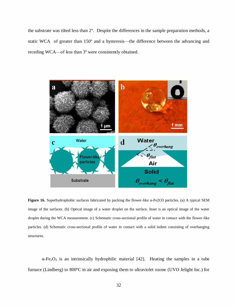
To prove the important role of the flower-like morphology of the synthesized Fe2O3
particles for inducing the superhydrophobic behavior, we mechanically ground the particles
using an agate mortar to destroy their flower-like morphology (Fig. 17a) and repeated the
experiment. We found that surfaces made by packing these ground particles were hydrophilic
with static WCAs of less than 20º and sliding angles of greater than 90º, which was in an obvious
contrast to the results obtained from these particles before they were ground. We also made
surfaces by packing commercial Fe2O3 particles in two different sizes (2 m in Fig. 17b and 50
34
nm in Fig. 17c in diameter, respectively, purchased from Sigma Aldrich) that did not have the
flower-like morphology, and found that the samples made using these particles were also
hydrophilic. The results of the WCA measurements are summarized in Table 3.
Figure 17. SEM images of (a) mechanically ground particles, (b) commercial micrometer-sized particles, and (c)
commercial nanometer-sized particles. Insets are the optical images of the water droplet during the WCA
measurement.
α-Fe2O3 is one of the most stable metal oxides in nature [42]. We therefore anticipate
that the fabricated surfaces consisting of the flower-like α-Fe2O3 particles can not be further
oxidized, and the superhydrophobicity of the surfaces can be preserved for a long time in
laboratory ambient conditions. Indeed, these surfaces retained their superhydrophobicity after
being stored in ambient laboratory air (20°C and 40% relative humidity) for 4 months. We
further carried out ageing tests by placing these samples in extremely oxidative environments—
they were heated to 800ºC in air for 10 hours, and exposed to ultra-violet ozone (UVO) for 10
hours. No significant changes in the WCAs or hysteresis were observed after these treatments
(Table 3).

35
Table 3. Results of WCA measurements on surfaces made by packing α-Fe2O3 particles with different morphologies
before and after ageing treatments.
WCA measured after ageing treatments (º)
Hematite particles*
WCA measured
on fresh sample
(º)
Stored in ambient
laboratory air for 4
months
Heated in air at
800°C for 10
hours
Exposed to UVO
for 10 hours
Synthesized
flower-like
particles
Static WCA 159 ± 2 157 ± 2 158 ± 2 157 ± 2
Hysteresis ~ 2 ~ 2 ~ 2 ~ 2
Sliding angle < 2 < 2 < 2 < 2
Synthesized
particles after they
were mechanically
ground into
irregular shapes
Static WCA 17 ± 3 16 ± 3 17 ± 3 17 ± 3
Sliding angle >90 >90 >90 >90
Commercial
particles of 2 μm
in average
diameter
Static WCA 13 ± 3 12 ± 3 15 ± 3 12 ± 3
Sliding angle >90 >90 >90 >90
Commercial
particles of 50 nm
in average
diameter
Static WCA <10 <10 <10 <10
Sliding angle >90 >90 >90 >90
*All the samples are made by compressing particles into a tablet using a pellet die to remove the effect of any possible organic contaminations
from the adhesion layer that is needed when other approaches are used to pack the particles on the substrate.

36
3.2.3 Conclusion
In this work, it is evident that the flower-like morphology of the synthesized Fe2O3 particles—
micrometer-sized spheres with nanometer-sized protrusions—is essential for making the surfaces
consisting of these particles superhydrophobic. Such superhydrophobicity is induced by the
overhang structures present on the surface and does not require the material to be intrinsically
hydrophobic. After the ageing tests, because the α-Fe2O3 particles retain their flower-like
morphology (as confirmed by SEM and TEM characterizations), the superhydrophobicity of the
surfaces made by packing these particles is preserved. Because a variety of flower-like
structures have been synthesized and reported in the literatures [43-45], we anticipate that the
demonstrated approach of packing flower-like structures could also be applied to many other
materials for fabrication of non-ageing superhydrophobic surfaces. Such surfaces may provide a
solution to the ageing and decay problems that currently hinder the practical applications of
artificial superhydrophobic surfaces.
3.3 SUPER WATER AND OIL-REPELLENT SURFACES ON INTRINSICALLY
HYDROPHILIC AND OLEOPHILIC POROUS SILICON FILMS
In this section, we report a convenient approach to fabricate porous Si films that are able to
induce a superoleophobic behavior on intrinsically oleophilic surfaces. The porous Si films are
fabricated by a gold-assisted electroless etching process, which produces a hierarchical porous
structure that consists of micrometer-sized asperities superimposed onto a network of tilted
nanometer-sized pores. The hierarchical porous structure forms textures with overhanging
37
structures on the surface, which are able to induce a superhydrophobic behavior on the
intrinsically hydrophilic Si surface. After chemically modified with a self-assembled monolayer
(SAM) of fluorinated organic molecules, which provides a lower surface free energy, the porous
Si films become super oil-repellent to diethylene glycol and hexadecane with rough of greater
than 150º, although the coated Si surface is intrinsically oleophilic with flat of less than 90º for
these oils. It is speculated that this superoleophobic phenomenon is induced by the overhang
structures present on the surface following the same mechanism that induces the
superhydrophobic phenomenon on intrinsically hydrophilic materials.
3.3.1 Experimental design and methodology
Two types of porous Si films were prepared in our experiment—one has tilted pores, and the
other has vertically aligned straight pores. The first type of porous Si was prepared by gold
(Au)-assisted electrochemical etching process. In this process, a p-type Si (111) wafer (Boron-
doped, 1-10 Ω∙cm) purchased from Silicon Quest International, Inc. was used. It was diced to 1
cm × 1 cm chips for the experiment. The Si surface was first coated with Au nanoclusters,
which served as the electrochemical reaction center during the etching step. The Au coating
solution was made by dissolving 0.01 M KAuCl4 (99.995%, Aldrich) in 10 % HF aqueous
solution (EMD). The Si chips were dipped in the coating solution at room temperature for 30
seconds, and then were soaked in an etching solution at 50oC for a variety of periods. The
etching solution was made by dissolving 0.135 M Fe(NO3)3 (Fisher Scientific) in 10% HF
aqueous solution. After the etching process, the samples were rinsed by ethanol, deionized water
and dried by nitrogen gas.

38
The second type of porous Si with the vertically aligned straight pores was prepared by
anodic etching of Si (100) chips. A p-type silicon (100) wafer (Boron-doped, <1mΩ∙cm) was
purchased from Siltronix (France), and diced into 2 cm × 2 cm chips. A Teflon electrochemical
cell that exposed 1.6 cm2 of the Si chip was employed for the anodic etching process. The
etching solution consisted of 3:1 (v/v), 48% aqueous HF–ethanol solution. A direct current at a
density of 100 mA/cm2 was applied for 10 min. After the etching process, the samples were
rinsed by ethanol, deionized water and dried by nitrogen gas.
Prior to the SAM coating process, the samples were firstly exposed to ultraviolet ozone
(UVO) (Jelight Inc.) for 15 min at room temperature to oxidize the Si surface. The samples were
then immersed into the SAM coating solution, made by dissolving 0.5 mM (tridecafluoro-
1,1,2,2,-tetrahydrooctyl) trichlorosilane (FTS) (n-C6F13CH2CH2SiCl3, Gelest Inc.) into a 4:1
(v/v) mixture of hexadecane (anhydrous, Sigma-Aldrich) and chloroform (anhydrous, Sigma-
Aldrich). After ~15 minutes, the samples were sequentially rinsed with isooctane (Sigma-
Aldrich), isopropanol (Fisher Scientific), deionized water, and then dried by nitrogen gas.
Scanning electron microscopy (SEM) images were taken by a Philips XL-30 field-
emission SEMsetup. The contact angle was measured using a VCA-OPTIMA drop shape
analysis system (AST Products, Inc.) with a computer-controlled liquid dispensing system and a
motorized tilting stage. Droplets of liquids in a volume of 5 L were used to measure the static
contact angle. The advancing and receding angles were recorded during the expansion and
contraction of the droplets induced by placing a needle in the water droplets and continuously
supplying and withdrawing water through the needle. The sliding angle was measured by tilting
the stage and recorded when the droplet began to move in the downhill direction. The
experiments were performed under normal laboratory ambient conditions (20 °C and 40%

39
relative humidity). Each contact angle measurement was repeated three times at different places
on the sample, and the mean value was reported.
3.3.2 Results and discussion
Au-assisted electroless etching processes have been previously employed to prepare Si
nanowires and porous Si films [46]. The process is applied here to make hierarchical porous
structures on Si surfaces. Au clusters were first deposited onto the Si surface via a galvanic
displacement reaction mechanism, by dipping the Si chip in an aqueous solution containing
KAuCl4 and HF. The chip was then transferred to an etching solution containing Fe(NO)3 and
HF, where pores were formed by oxidizing Si while reducing Fe3+
. The Au clusters coated onto
the Si prior to the etching step are believed to act as the local electrodes that attract electrons
from the Si underneath and facilitate Si oxidation and dissolution during the etching process, as
shown in Figure 18. Therefore, pores are formed where the Au clusters are present, and the Au
clusters sink into the pores as the etching proceeds.
Figure 18. Schematic of Au-assisted electroless etching

40
Since the etching prefers to proceed along the Si <100> direction, on a (111) Si surface,
tilted pores are formed. Figs. 19a and b show the representative top and cross-sectional SEM
images of the as-fabricated porous silicon films after 1 hour etching. A network of tilted pores in
nanometer scales is clearly seen in these images. In addition, asperities in the micrometer scale
are observed, and the topography of the asperities is superimposed onto the network of
nanometer pores.
Figure 19. Porous silicon surface fabricated by Au-assisted electroless etching. (a) Top-view SEM image. (b) Cross-
sectional view SEM image. The inset is an optical image of a water droplet on the surface. (c) Schematic cross-
sectional profile of water in contact with the porous silicon surface.
The as-fabricated sample was superhydrophobic. The static water contact angle was
measured to be ~160º (Fig. 19b inset). The hysteresis—the difference between the advancing
and receding angle—was measured to be less than 2°, and water droplets (~ 5 μl) roll off the
substrate at a sliding angle of less than 2°. Because no organic chemicals are involved in the
entire fabrication process to further decrease the surface free energy, we attribute the observed
superhydrophobic phenomenon on the intrinsically hydrophilic Si surface to the hierarchical
topographic characteristic of the porous Si.
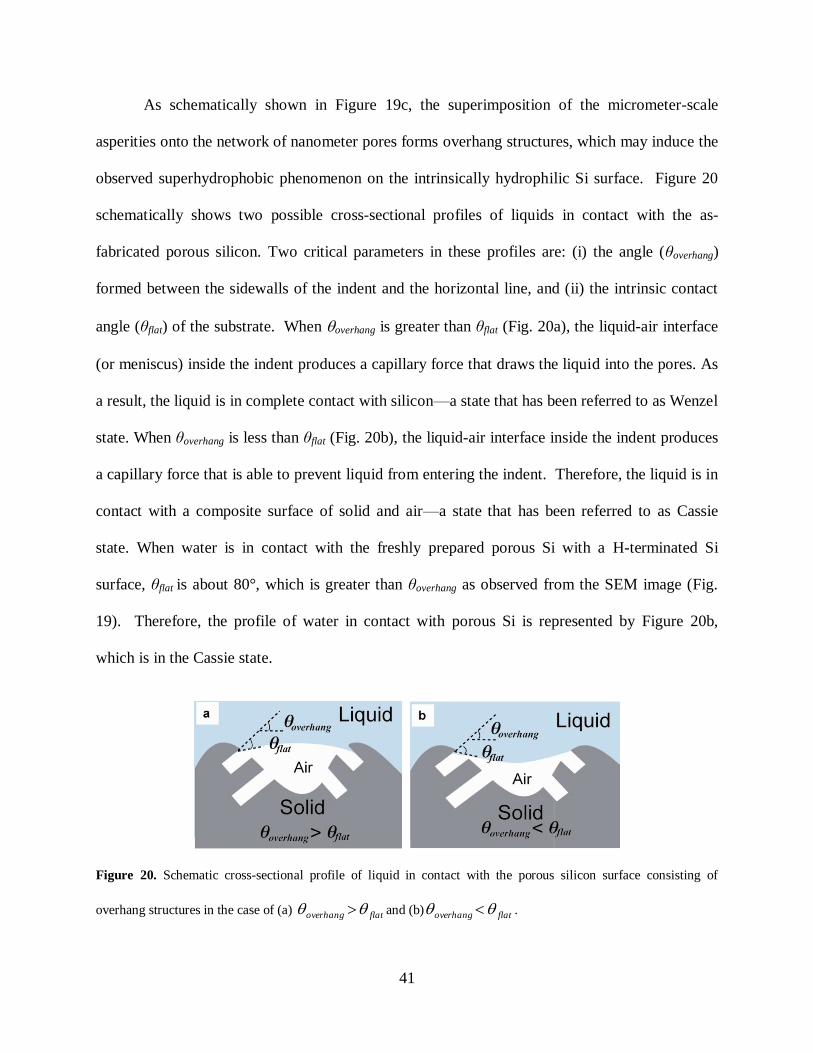
41
As schematically shown in Figure 19c, the superimposition of the micrometer-scale
asperities onto the network of nanometer pores forms overhang structures, which may induce the
observed superhydrophobic phenomenon on the intrinsically hydrophilic Si surface. Figure 20
schematically shows two possible cross-sectional profiles of liquids in contact with the as-
fabricated porous silicon. Two critical parameters in these profiles are: (i) the angle (θoverhang)
formed between the sidewalls of the indent and the horizontal line, and (ii) the intrinsic contact
angle (θflat) of the substrate. When overhang is greater than θflat (Fig. 20a), the liquid-air interface
(or meniscus) inside the indent produces a capillary force that draws the liquid into the pores. As
a result, the liquid is in complete contact with silicon—a state that has been referred to as Wenzel
state. When θoverhang is less than θflat (Fig. 20b), the liquid-air interface inside the indent produces
a capillary force that is able to prevent liquid from entering the indent. Therefore, the liquid is in
contact with a composite surface of solid and air—a state that has been referred to as Cassie
state. When water is in contact with the freshly prepared porous Si with a H-terminated Si
surface, θflat is about 80°, which is greater than θoverhang as observed from the SEM image (Fig.
19). Therefore, the profile of water in contact with porous Si is represented by Figure 20b,
which is in the Cassie state.
Figure 20. Schematic cross-sectional profile of liquid in contact with the porous silicon surface consisting of
overhang structures in the case of (a) flatoverhang and (b) flatoverhang .

42
The experiment was repeated on porous Si samples prepared by varying the etching time,
which produced surfaces with varied s . The static water contact angle (WCA) on these
samples were measured and plotted in Figure 21. It was observed that the static WCA increased
from ~ 102° to 162° as the etching time increased from 5 min to 40 min, while after 40 min,
etching the Si for a longer time did not significantly increase the contact angle. The increase in
the WCA as a function of the etching time is likely due to a decrease in s when the Si is etched
for a longer time.
Figure 21. Static water contact angle measured on the porous Si as a function of the etching time.

43
To prove the important role that the surface topography plays in inducing the
superhydrophobic phenomenon on the Si surface with tilted pores, porous Si with vertically
aligned straight pores were fabricated by anodic etching and the wetting phenomenon on such
porous Si surfaces was examined. Figure 22a shows an SEM image of the as-fabricated porous
silicon by anodic etching. The nanometer-sized pores are vertically aligned along the surface
normal direction of the Si chip, and no micrometer-sized asperities are present on the surface.
The porous Si surfaces with straight pores exhibit hydrophilic behavior. It can be explained that,
when water is in contact with such surfaces (schematically shown in Fig. 22b) without the
presence of overhanging structures, the capillary force will draw water into the pores. As a
result, water is in complete contact with silicon.
Figure 22. Water in contact with the porous Si with vertically aligned straight pores. (a) Representative SEM image
of the porous silicon with vertically aligned straight pores. The inset is an optical image of a water droplet on the
surface. (b) Schematic cross-sectional profile of water in contact with the porous silicon surface, where
flatoverhang .
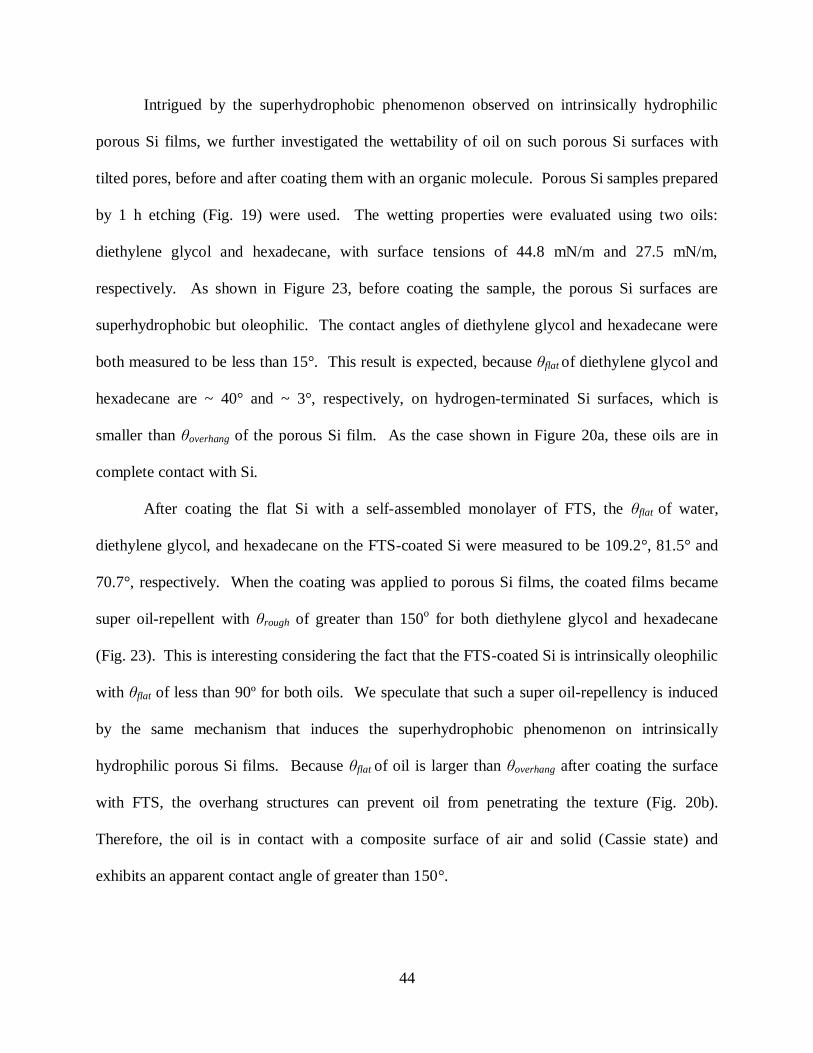
44
Intrigued by the superhydrophobic phenomenon observed on intrinsically hydrophilic
porous Si films, we further investigated the wettability of oil on such porous Si surfaces with
tilted pores, before and after coating them with an organic molecule. Porous Si samples prepared
by 1 h etching (Fig. 19) were used. The wetting properties were evaluated using two oils:
diethylene glycol and hexadecane, with surface tensions of 44.8 mN/m and 27.5 mN/m,
respectively. As shown in Figure 23, before coating the sample, the porous Si surfaces are
superhydrophobic but oleophilic. The contact angles of diethylene glycol and hexadecane were
both measured to be less than 15°. This result is expected, because θflat of diethylene glycol and
hexadecane are ~ 40° and ~ 3°, respectively, on hydrogen-terminated Si surfaces, which is
smaller than θoverhang of the porous Si film. As the case shown in Figure 20a, these oils are in
complete contact with Si.
After coating the flat Si with a self-assembled monolayer of FTS, the θflat of water,
diethylene glycol, and hexadecane on the FTS-coated Si were measured to be 109.2°, 81.5° and
70.7°, respectively. When the coating was applied to porous Si films, the coated films became
super oil-repellent with θrough of greater than 150o for both diethylene glycol and hexadecane
(Fig. 23). This is interesting considering the fact that the FTS-coated Si is intrinsically oleophilic
with θflat of less than 90º for both oils. We speculate that such a super oil-repellency is induced
by the same mechanism that induces the superhydrophobic phenomenon on intrinsically
hydrophilic porous Si films. Because θflat of oil is larger than θoverhang after coating the surface
with FTS, the overhang structures can prevent oil from penetrating the texture (Fig. 20b).
Therefore, the oil is in contact with a composite surface of air and solid (Cassie state) and
exhibits an apparent contact angle of greater than 150°.

45
Figure 23. Static contact angles of water, diethylene glycol, and hexadecane on flat silicon (Si), porous silicon (PS),
flat silicon coated with FTS (FTS-Si) and porous silicon coated with FTS (FTS-PS).
3.3.3 Conclusion
We have demonstrated a convenient approach to fabrication of porous Si films that are able to
induce a superhydrophobic behavior on an intrinsically hydrophilic Si surface and a
superoleophobic behavior on an intrinsically oleophilic FTS-coated Si surface. The hierarchical
porous structure of the films forms overhang structures on the surface, which play an important

46
role in inducing the superhydrophobic and superoleophobic phenomena. Certainly, problems
such as the dynamic behavior of the oils on the superoleophobic surfaces and the quantitative
evaluation of the stability of the Cassie state still need further investigation. Nonetheless, it is
anticipated that the demonstrated approach and principle could be applied to expand the range of
materials that can be used to fabricate superhydrophobic and, in particular, superoleophobic
surfaces.
3.4 TRANSPARENT SUPERHYDROPHOBIC AND HIGHLY OLEOPHOBIC
COATINGS
In this section, we report a facile process for fabrication of transparent superhydrophobic and
highly oleophobic surfaces through assembly of silica nanoparticles and sacrificial polystyrene
nanoparticles. The silica and polystyrene nanoparticles are first deposited by a layer-by-layer
assembly technique. The polystyrene nanoparticles are then removed by calcination, which
leaves a porous network of silica nanoparticles. The cavities created by the sacrificial
polystyrene particles form overhang structures on the surfaces. Modified with a fluorocarbon
molecule, such surfaces are superhydrophobic and transparent. They also repel liquids with low
surface tensions, such as hexadecane, due to the overhang structures that prevent liquids from
getting into the air pockets even though the intrinsic contact angles of these liquids are less than
90°.
It is generally recognized that the superhydrophobicity, either natural or artificial, is a
result of the interplay between the surface chemical composition and the surface texture with a
two-tier roughness in micrometre and nanometre scales, respectively, for each tier. Because the

47
surface textures with the two-tier roughness may induce significant light scattering, fabrication
of transparent superhydrophobic surfaces has been a difficult task. By optimizing and
manipulating surface topographies through delicate approaches, e.g., by layer-by-layer assembly
[47, 48], using eutectic liquids [49], and depositing silicone nanofilaments [50], several groups
have successfully fabricated transparent superhydrophobic surfaces, which are promising for
many applications where the substrate material needs to be rendered superhydrophobic without
significantly changing its optical properties. However, these transparent superhydrophobic
surfaces are vulnerable to oil contamination—they repel water but not oil, and contamination of
liquids with a low surface tension such as vegetable oil can easily remove their
superhydrophobicity. Therefore, to fully explore the potential applications of transparent
superhydrophobic surfaces, it is desirable to make them repel not only water but also oil and
liquids with a low surface tension.
Fabricating superhydrophobic surfaces that are able to repel oil in the same manner as
they repel water has been challenging, because this typically requires the solid surface to possess
a sufficiently low surface free energy so that its intrinsic oil contact angle is greater than 90°,
which in practice has been exceptionally difficult if possible at all. Recently, it has been
demonstrated that by fabricating ‗‗overhang‘‘ or “re-entrant”structures on the surface, the
requirement on the extremely low surface free energy may be relaxed, and surfaces that are both
super water-repellent and super oil-repellent have been achieved [40, 51]. However, these
coatings are not transparent, and we are unaware of published work to make transparent coatings
with super repellencies to both water and oil. Herein, we develop a facile process for fabrication
of transparent superhydrophobic and highly oleophobic surfaces by first depositing silica

48
nanoparticles and sacrificial polystyrene nanoparticles through a layer-by-layer assembly
technique, and then remove the sacrificial polystyrene particles by calcination.
3.4.1 Experimental design and methodology
Materials. Poly(sodium 4-styrenesulfonate) (PSS, Mw=70,000), poly(diallyldimethylammonium
chloride) (PDDA, 20 w.t.%), TM-40 colloidal silica (40 w.t.% suspension in water, ca. 20 nm
diameter silica particles), chloroform (anhydrous), hexadecane (anhydrous) and isooctane were
obtained from Sigma-Aldrich. Negatively charged polystyrene nanoparticles (8 w.t.% solid, 60
nm in diameter) were obtained from Interfacial Dynamics Corp. Isopropanol was obtained from
Fisher Scientific. (Tridecafluoro-1,1,2,2-tetrahydrooctyl) trichlorosilane (n-C6F13CH2CH2SiCl3,
abbreviated as FTS, >95%) was purchased from Gelest Inc. De-ionized (DI) water was prepared
using the Milli-Q (Millipore) system.
Substrate preparation. Before the coating process, the substrates were cleaned by immersion
in piranha solution (3:1 mixture of 98 w.t.% H2SO4 and 30 w.t.% H2O2; piranha solutions may
result in explosion or skin burns if not handled with extreme caution) for 15min, thoroughly
rinsed with DI water, and dried with a nitrogen flow. This process rendered the freshly cleaned
substrates negatively charged in solution.
Layer-by-layer assembly of nanoparticles. During the assembly, the substrates were
repetitively immersed into cationic and anionic aqueous solutions. In each cycle, the substrates
were first immersed into cationic solutions, followed by rinsing with DI water and drying with a
nitrogen flow. Then, the substrates were immersed into anionic solutions, followed by the same

49
rinsing and drying steps. One bilayer was formed upon completion of each cycle. The assembly
process started with deposition of five bilayers of PDDA and PSS, [PDDA/PSS]5, before
deposition of nanoparticles. A few bilayers of polymers, such as [PDDA/PSS]5, have been
shown to promote the adhesion of the film to the substrate during the subsequent layer-by-layer
assembly of nanoparticles [47,48]. For deposition of [PDDA/PSS]5, PDDA was used to make
the cationic aqueous solution (2 mg mL-1
, pH 4), and PSS was used to make the anionic aqueous
solution (2 mg mL-1
, pH 4). After five bilayers of PDDA and PSS were deposited, deposition of
body layers started by switching the anionic solution from the PSS solution to an aqueous
solution (pH 9.0) containing two kinds of nanoparticles with different sizes (60 nm polystyrene +
20 nm SiO2, ca. 0.04 wt% each), while the PDDA aqueous solution was still used as the cationic
solution. To investigate the effect of the number of the body bilayers on the wettability, samples
with 5, 10, 15, 20 and 25 bilayers of nanoparticles, [PDDA/(60 nm polystyrene + 20 nm SiO2)]x
(where x denotes the number of body bilayers), respectively, were prepared. For each coating of
[PDDA/(60 nm polystyrene + 20 nm SiO2)]x, two sets of samples were prepared and compared.
One set was used without removing the polystyrene particles while the other set was calcined as
described below to remove the polystyrene particles before it was functionalized with FTS.
Calcination of the coatings. One set of the [PDDA/(60 nm polystyrene + 20 nm SiO2)]x samples
was calcined at 550 °C for 4 h, during which both the polystyrene particles and polyelectrolytes
were removed from the coatings and a nanoporous network of silica nanoparticles was formed.
Surface functionalization of the coatings. Both sets of the [PDDA/(60 nm polystyrene + 20 nm
SiO2)]x samples were finally functionalized with FTS. The samples, either directly after layer-

50
by-layer assembly or after calcination, were treated with ultraviolet ozone (UVO) (Jelight Inc.)
for 5 min. Then, they were immersed into a coating solution, made by dissolving 0.5 mM FTS
into a 4:1 (v/v) mixture of hexadecane and chloroform. After 15 min, the samples were
thoroughly rinsed by isooctane, isopropanol, and DI water, sequentially.
Characterization. The contact angle was measured using a VCA-OPTIMA drop shape analysis
system (AST Products, Inc.) with a computer-controlled liquid dispensing system. Droplets of
liquids in a volume of 5 ml were used to measure the static contact angle. The advancing and
receding angles were recorded during expansion and contraction of the droplets induced by
placing a needle in the liquid droplets and continuously dispensing and withdrawing liquid
through the needle. All of the tests were performed under normal laboratory ambient conditions
(20 °C and 40% relative humidity). Each contact angle measurement was repeated three times at
different places of the sample, and the average value was reported. Scanning electron
microscopy (SEM) images were taken by a Philips XL-30 field emission SEM setup.
Transmittance was measured by a UV-Vis-NIR microspectrophotometer (Craic QDI 2010).
3.4.2 Results and discussion
The process for preparing the coatings is schematically shown in Figure 24 and detailed in the
experimental section. It mainly consists of two steps: (i) layer-by-layer assembly of silica
nanoparticles and sacrificial polystyrene nanoparticles and (ii) removal of sacrificial polystyrene

51
Figure 24. Schematic process for preparing the coatings. (a) Layer-by-layer assembly of 20 nm silica (SiO2)
nanoparticles and 60 sacrificial polystyrene (PS) nanoparticles. Adhesion layers are deposited before the deposition
of body layers. (b) The assembled nanocomposite coating is treated by UVO and functionalized by FTS either
directly after the assembly or after removal of the sacrificial PS particles through calcination.

52
nanoparticles by calcination. The layer-by-layer assembly process employed here is similar to
previously published methods [47, 48], which are based on deposition of positively and
negatively charged particles, polymers, or particle-polymer complexes alternately in sequential
cycles. In our process, five bilayers of PDDA and PSS, [PDDA/PSS]5, were first deposited as
adhesion layers. Then, samples with 5, 10, 15, 20 and 25, bilayers of nanoparticles, [PDDA/ (60
nm polystyrene + 20 nm SiO2)]x (where x denotes the number of body bilayers), respectively,
deposited on top of the adhesion layers were prepared. By virtue of electrostatic interactions
involved in this process, organic–inorganic nanocomposite coatings consisting of different
numbers of body layers were readily achieved. As expected, the thickness and the roughness of
the coatings monotonically increased in a well controlled manner with increasing numbers of
bilayers. This feature of the layer-by-layer assembly technique provides us with the capability to
gradually tune the surface roughness and study its effect on the wettability and transparency of
the coatings, and is particularly advantageous when both superhydrophobicity and transparency
are desired.
For each coating of [PDDA/(60 nm polystyrene + 20 nm SiO2)]x, two sets of samples
were prepared and compared. One set was treated by UV ozone and functionalized by FTS
without removing the sacrificial polystyrene particles, while the other set was calcined to remove
the sacrificial polystyrene particles before it was functionalized with FTS. Figure 25 shows the
SEM images of the coatings with 25 bilayers before and after removing the polystyrene particles.
As shown in Figure 25a, after the layer-by-layer assembly process, the smaller-sized silica
particles (ca. 20 nm) crowd around the bigger-sized polystyrene particles (ca. 60 nm). After the
calcination process, the bigger sacrificial polystyrene particles are removed (Figure 25b) while

53
leaving behind cavities with a similar size and shape, resulting in a porous network of silica
nanoparticles.
Figure 25. SEM images of the coatings. (a) and (b) are SEM images of the coatings with 25 bilayers before and
after removing the sacrificial polystyrene particles, respectively. Labeled in (a) are a representative 60 nm
polystyrene particle (labeled by ―1‖) and a representative 20 nm silica particle (labeled by ―2‖). The polystyrene
particles disappear in (b) after calcination. The scale bars are 200 nm.
After functionalizing both sets of samples with FTS, the hydrophobicity of these coatings
is examined. Figs. 26a and b present the advancing and receding angles of water droplets on
these two sets of coatings as a function of the number of the bilayers. On the first set of coatings
which are prepared without removing the sacrificial polystyrene particles, the advancing angles
are all in excess of 150°. However, large contact angle hysteresis (the difference between the
advancing and the receding angles) of more than 90° is observed on all these samples and it
increases with increasing the number of the bilayers. The combination of large advancing angles

54
Figure 26. Advancing and receding contact angles as a function of the number of the bilayers on (a) the first set of
coatings that are prepared without removing the sacrificial polystyrene particles and (b) the second set of coatings
that are prepared after removing the sacrificial polystyrene particles.
and large hysteresis indicates that water droplets on these surfaces are most likely in a Wenzel
state. In the Wenzel state, water is in complete contact with the rough solid surface, and the

55
apparent contact angle on the rough surface ( rough ) can be correlated to the intrinsic contact
angle of the solid surface ( flat ) by the Wenzel‘s equation (Eqn. 3). Since flat of the FTS-
grafted surface is ~ 110°, according to Eqn. 3, rough will increase as r increases. Therefore, as
the number of the bilayers increases and thus r increases, the advancing contact angle of the
coatings increases. On the other hand, water droplets in the Wenzel state on a rough surface are
known to exhibit a large hysteresis, which is also consistent with our result.
During the wettability test on the second set of the coatings which are essentially porous
networks of silica nanoparticles after removing the polystyrene particles, a transition in the
wetting regime is clearly observed as the number of bilayers increases. As seen in Figure 26b,
the advancing contact angles on this set of samples are all greater than 150°, but the hysteresis
decreases significantly from ~ 87° for 5 bilayers to ~ 4° for 25 bilayers. When the number of
bilayers is small, both the advancing contact angle and the hysteresis are large, which is similar
to what has been observed on the first set of samples. Therefore, the system is in the Wenzel
wetting regime. However, as the number of bilayers increases to 25, both a large advancing
contact angle and small hysteresis are observed, which indicates that the system is in the Cassie
wetting regime. When the number of bilayers is between 5 and 25, water droplets on the
coatings gradually transit from the Wenzel state to the Cassie state.
In the Cassie state, liquid is in contact with a composite surface of solid and air, and
forms droplets (known as fakir droplets). The apparent contact angle rough , in this case, has
been correlated to flat by the Cassie–Baxter equation. By setting the Wenzel and Cassie-Baxter
equations equal to each other, one can solve flat , which corresponds to a critical angle c which
is greater than 90°, as determined by Eqn. 5. When flatc , the Cassie state is

56
thermodynamically more favorable; otherwise, the Wenzel state is preferred. We believe that a
decrease in c is responsible for the transition of the system from the Wenzel state to the Cassie
state as the number of bilayers increases. Because the roughness of the coating and thus r
increases with increasing the number of bilayers, c decreases according to Eqn. 5. f l a t , on the
other hand, is determined by the surface chemical composition of the coating, which in this case
is the tethered FTS molecule. This means that flat does not change significantly with the
number of bilayers. Therefore, it is very likely that as the number of bilayers increase, c will
change from a value that is originally greater than flat to a value that is smaller than flat .
Correspondingly, the system transits from the Wenzel to the Cassie wetting regimes.
The difference between the completely two different states that water is in on the two sets
of coatings, before and after the sacrificial polystyrene particles are removed, respectively, may
also be explained by the decrease in c . As presented in Figure 26b, removal of polystyrene
particles will create cavities between the network of silica particles and apparently will increase
the actual solid surface area and hence r. This, in turn, will result in a decrease in c . Because
the difference in flat between the two sets of these coatings is very small, c could decrease from
a value that is greater than flat when the polystyrene particles are not removed, to a value that is
smaller than flat after the polystyrene particles are removed. We believe that this decrease of c
accompanying the removal of the polystyrene particles induces the Wenzel-to-Cassie wetting
regime transition.
In addition to the much larger r which induces the wetting regime transition of water on
the coatings, removal of sacrificial polystyrene particles creates an important surface texture on
the coating surfaces, known as ―overhang‖ [51-53] or ―re-entrant‖ [40] structures. Such surface

57
textures are able to induce a metastable Cassie state when liquid is in contact with the rough
solid surface even when flat is less than 90° and certainly less than c . The application of this
mechanism to our system results in a coating that repels both water and oil with low surface
tensions such as hexadecane (surface tension ca. 27.5 mN/m). Figs. 27a and b present
photographs of a glass slide coated with 25 bilayers of polystyrene and silica nanoparticles,
followed by calcination and functionalization with FTS. Both water and hexadecane form small
beads when they are in contact with the coating. The contact angle of water is in excess of 160°
with a small hysteresis of less than 5°. The contact angle of hexadecane on the coating is in
excess of 140°, although the flat of the FTS-grafted surface for hexadecane is only about 70°,
which is much less than 90°. We believe that this high oil repellency of the coating is induced
by the overhang structures on the surface which is formed during the removal of the sacrificial
polystyrene particles.
Remarkably, the superhydrophobic and highly oil-repellent coating fabricated by this
approach is also highly transparent. Because the polystyrene particles employed in this process
are opaque, the transparency of the nanocomposite coatings fabricated by the layer-by-layer
assembly process gradually decreases with increasing the number of the deposited bilayers
during the assembly process. This effect becomes more apparent as the number of the bilayers
exceeds 15, when the glass slide starts turning translucent. However, after the polystyrene
particles are removed in the calcination step, the transparency of the glass slide recovers. This is
evident from the photographs shown in Figs. 27a and b where the glass slide has been coated
with 25 bilayers. Comparison of the transmission spectra of the glass slide before and after the
coating process (shown in Fig. 27c) indicates that no significant decrease in the transparency of

58
the glass slide is observed after it is coated, which further proves the high transparency of the
coating.
3.4.3 Conclusions
We have demonstrated that a transparent superhydrophobic and highly oleophobic coating can be
fabricated based on a porous network of nanoparticles. The porous network can be constructed
by first assembling an organic–inorganic nanocomposite and then removing the organic moieties
by calcination. One example of this approach that we have shown in this work is to first
construct a silica-polystyrene nanocomposite by using a layer-by-layer assembly technique and
then remove the sacrificial polystyrene particles by calcination. The resulting nanoporous
structure is highly transparent and can be made both superhydrophobic and highly oleophobic
after functionalization with a fluorocarbon molecule. We believe that removal of the polystyrene
particles from the nanocomposite forms overhang structures on the surface of the nanoporous
structure, which induces the high oil-repellency of the coating even though the intrinsic oil
contact angle of the solid surface is less than 90°. Although transparent superhydrophobic
coatings have been demonstrated using the layer-by-layer assembly technique previously, to the
best of our knowledge, this is the first time the fabrication of transparent coatings that are both
superhydrophobic and highly oleophobic by using the layer-by-layer assembly technique has
been demonstrated. In addition, a key innovation in our process is the employment of sacrificial
organic particles, which not only form overhang structures for inducing the oil-repellency but
also saves the final step of adding a top layer of smaller particles which has been previously
employed in the literature for making transparent superhydrophobic coatings.

59
Figure 27. Photographs of a coated glass slide with droplets of (a) water and (b) hexadecane to demonstrate the
superhydrophobicity, high oil-repellency, and transparency of the coating. Insets in (a) and (b) are images taken
during the contact angle measurement. (c) Transmission spectrum of the glass slide before and after the coating
process. The glass slide is coated with 25 bilayers, and is calcinated and functionalized with FTS.

60
4.0 APPLICATIONS OF SUPERHYDROPHOBIC SURFACES
4.1 ANTI-ICING
4.1.1 Introduction
One attractive application of superhydrophobic surfaces, in addition to the extraordinary water-
repellency, is their speculated capability to reduce accumulation of snow and ice and to even
completely prevent formation of ice on solid surfaces. Several groups have studied the adhesion
of ice on superhydrophobic surfaces and have found correlations, with a reasonable degree of
success, between reduction in ice adhesion and the superhydrophobicity of surfaces [54-56].
However, we are unaware of published research to study ice formation on superhydrophobic
surfaces.
Among numerous problems caused by icing, many are due to striking of supercooled water
droplets onto a solid surface. Such icing caused by supercooled water, also known as ―freezing
rain‖, ―atmospheric icing‖, or ―impact ice‖, is notorious for glazing roadways, breaking tree
limbs and power lines, and stalling airfoil of aircrafts, which may cause immeasurable economic
losses [57, 58]. Whereas extensive work has been published on superhydrophobicity, up to date
there is little experimental/theoretical work on ice formation from supercooled water on
superhydrophobic surfaces. The speculation on the anti-icing property of superhydrophobic

61
surfaces, especially when supercooled water droplets strike such surfaces, has been under debate
for many years. However, up to date, no literature has clearly discussed ice formation of
supercooled water on superhydrophobic surfaces. As a result, the speculation on the anti-icing
property of superhydrophobic surfaces, especially when supercooled water droplets strike such
surfaces, has been under debate for many years.
In this work, we study the anti-icing property of superhydrophobic coatings prepared by
using nanoparticle-polymer composites. We demonstrate that when the size of the particles in
these composites is in the right range, the coatings are able to prevent ice formation upon impact
of supercooled water both in laboratory conditions and in naturally occurring environments.
More importantly, we find that the anti-icing capability of these composites depends not only on
their superhydrophobicity but also on the size of the particles exposed on the surface. The
critical particle sizes that determine the superhydrophobicity and the anti-icing property are in
two different length scales. These results open up possibilities for rational design of anti-icing
superhydrophobic surfaces by tuning surface textures in multiple length scales.
4.1.2 Experimental section
Synthesis of acrylic polymer resin. In a typical process, the acrylic polymer was synthesized
by a free radical polymerization of styrene, butyl acrylate, butyl methacrylate, and glycidyl
methacrylate in toluene using azodiisobutyronitrile (AIBN) as the initiator. All these chemicals
were purchased from Sigma-Aldrich. In a three-necked round-bottomed flask equipped with a
magnetic stirrer, a condenser, a funnel, and a thermometer, 3.13 g styrene, 1.92 g butyl acrylate,
12.32 g butyl methacrylate, 4.25 g glycidyl methacrylate, and 100 ml toluene were mixed. The
mixture was stirred and heated to 85 oC. Then, the heat source was turned off. A solution of 0.2

62
g AIBN in 2.5 ml toluene was dropwise added into the flask. The reaction mixture was heated to
85 oC and stirred isothermally for 3 hr. Afterwards, the same amount of AIBN toluene solution
was added into the flask, and the mixture was stirred for another 3 hr. At the end of the reaction,
the mixture was cooled at room temperature. The resulting acrylic polymer was precipitated in
hexane and filtered, and then dried under vacuum at 40oC for 24 hr.
Preparation of the polymer binder. In a typical process, the polymer binder was prepared by
mixing 2.2 g of the synthesized acrylic polymer, 1.2 g of silicone resin (DOW CORNING® 840
RESIN, 60 wt% in toluene), 1.3 g toluene, and 0.6 g acetone. The binder can be cured either at
room temperature for 12 hr or at 80 oC for 2 hr. During the curing process, the reactive glycidyl
groups on the acrylic polymers crosslink with the silicone resin. The static water contact angle
of the cured binder is ~107o.
Preparation of the particle-polymer composites. The particle-polymer composites were
prepared by mixing about 2.5 g of the organosilane-modified silica particles in varied diameters
(20 nm, 50 nm, 100 nm, 1 m, 10 m, and 20 m) with 5 g of the polymer binder, 75 g toluene,
and 15 g acetone. They were applied on Al plates by a spray gun at a pressure of about 30 psi
and cured at room temperature for 12 hr.
Electron microscopy. SEM images were taken on a Philips XL-30 field emission SEM setup.
A thin palladium/gold film was sputtered on the sample before SEM images were taken.
Transmission electron microscopy images were taken using a JOEL 200CX microscope.
63
Contact angle measurement. The water contact angles were measured by using a VCA-
OPTIMA drop shape analysis system (AST Products, Inc.) with a computer-controlled liquid
dispensing system and a motorized tilting stage. Water droplets with a volume of 4 μl were used
to measure the static water contact angle. The advancing and receding angles were recorded
during expansion and contraction of the droplets induced by placing a needle in the water
droplets and continuously supplying and withdrawing water through the needle. The sliding
angle was measured by tilting the stage and recorded when the droplet began to move in the
downhill direction. Each measurement was repeated 3 times. The measurement was performed
under normal laboratory ambient conditions (20°C and 30% relative humidity).
Icing experiments using laboratory-made supercooled water. Supercooled water was
prepared by storing bottled pure water in a -20 oC freezer for 3 hr. The coated and uncoated Al
plates were also stored in the -20 oC freezer for 3 hr before the experiments and were tilted at an
angle of about 10 o to the horizontal plane during the experiments. Supercooled water was
poured onto the Al plates about 5 cm above the plates. Each experiment was repeated 20 times
to obtain the probability of ice formation on different samples.
Icing experiments using naturally occurred freezing rain. One side of an Al plate (10 cm×10
cm) was coated with a superhydrophobic composite made with ~ 50 nm organosilane-modified
silica particles, while the other side was untreated. A hole of about 1 cm in diameter was drilled
near one edge of the plate and a cotton thread was used to hang the Al plate outdoors. Half of a
commercial satellite dish antenna (SuperDish Network) was coated with the same composite
while the other half was untreated. Both the dish antenna and the Al plate were placed outdoors

64
in a typical whether condition (~ -10 oC) of Pittsburgh, PA, in January for 7 days before the
freezing rain occurred on the night of January 27, 2009.
4.1.3 Results and discussion
We made a series of particle-polymer composites by mixing a polymer binder with silica
particles ranging from 20 nm to 20 m in diameter. The polymer binder was synthesized by
cross-linking a silicone resin with an acrylic polymer. The polymer binds strongly to many
substrates including metal and glass, and has an intrinsic water contact angle of ~107°. The
surface of silica particles was modified with organosilane molecules. The intrinsic water contact
angle of the surface-modified silica particles is ~110°. The mixtures were sprayed onto
aluminum (Al) plates and cured at room temperature for 12 hr.
The measured water contact angles of these composites are plotted in Figure 28. All the
cured composites exhibit high water repellency. The composites prepared by using particles of
20 nm, 50 nm, 100 nm, 1 μm, and 10 μm in diameter all possess similar superhydrophobicity,
characterized by the larger than 150° advancing and receding angles with less than 2° hysteresis.
Only the composite prepared by using 20 μm particles has a less than 150° water contact angle
and about 4° hysteresis. To test the anti-icing capability of these composites, we poured
supercooled water (T = -20 oC) onto the coated Al plates from ~5 cm above and visually
inspected whether ice was formed upon the impact. Figure 29 shows typical images taken during
the experiment, which demonstrates the anti-icing property of the superhydrophobic
nanoparticle-polymer composites. During the experiment, supercooled water (-20 °C) was
poured onto two Al plates. The right plate was untreated, while the left one was coated with a
nanoparticle-polymer composite (with 50 nm particles). On the right plate, ice formed instantly

65
when the supercooled water impacted the plate. In contrast, on the left, ice did not form when
the supercooled water impacted the plate, but built up from the bottom edge where the plate was
in contact with an untreated Al tray. It is evident that the coating on the left Al plate is very
effective to prevent icing of supercooled water upon striking the surface.
Figure 28. Probability of ice formation and the advancing and receding angles of water droplets on each particle-
polymer composite as a function of the particle size.
The experiment was repeated 20 times for each sample to obtain the probability of ice
formation. The result is shown in Figure 28, where the icing probability is plotted with the
contact angles as a function of the size of the particles used in the composites. It is observed that
the critical particle sizes that determine the superhydrophobicity and the anti-icing property,
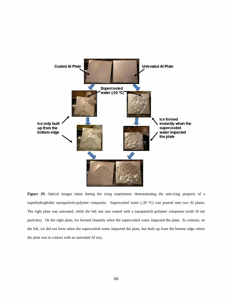
66
Figure 29. Optical images taken during the icing experiment, demonstrating the anti-icing property of a
superhydrophobic nanoparticle-polymer composite. Supercooled water (-20 °C) was poured onto two Al plates.
The right plate was untreated, while the left one was coated with a nanoparticle-polymer composite (with 50 nm
particles). On the right plate, ice formed instantly when the supercooled water impacted the plate. In contrast, on
the left, ice did not form when the supercooled water impacted the plate, but built up from the bottom edge where
the plate was in contact with an untreated Al tray.

67
Figure 30. Representative electron microscopy images of particle-polymer composites. a, Scanning electron
microscopy (SEM) image of a particle-polymer composite made with 20 nm silica particle. Scale bar, 1 µm. Inset,
transmission electron microscopy image. Scale bar, 50 nm. b, SEM image of a particle-polymer composite made
with 50 nm silica particles. Scale bar, 1 µm. c, SEM image of a particle-polymer composite made with 20 m silica
particles. Scale bar, 100 µm.
respectively, are in two different length scales. Although composites made with particles up to
10 μm in diameter are all superhydrophobic, the anti-icing capabilities of these coatings are
distinctly different—ice does not form on the samples prepared with 20 and 50 nm particles at
all, but the icing probability increases remarkably when the particle diameter is larger than 50
nm. Figure 30 shows three representative electron microscopy images of the cured composites
with 20 nm, 50 nm and 20 m particles, respectively. Based on these images, the structure of the
composites and the profile of water in contact with the composites are schematically shown in
Figure 31a. Water on these composites is primarily in contact with air pockets trapped in the
rough surfaces. According to the Cassie-Baxter equation, the large water contact angles on these
composites imply that only less than 15% of the solid part is in direct contact with water.
Therefore, when supercooled water impacts such surfaces, icing may occur through a
heterogeneous nucleation process at the contact between water and the particles exposed on the

68
surfaces. As a result, the kinetics of the ice nucleation process is determined by the size of the
particles exposed on the surfaces.
Figure 31. Heterogeneous nucleation on the surface of a superhydrophobic particle-polymer composite. (a)
Schematic cross-sectional profile of water in contact with a superhydrophobic particle-nanoparticle composite. (b)
Ratio (f) of the free-energy barrier for nucleation around a spherical particle relative to that in the bulk versus the
relative particle radius ( / cR r ).
The effect of the particle size on the energy barrier encountered by the heterogeneous
nucleation process can be estimated by using a classical heterogeneous nucleation theory [59].
The free energy barrier for heterogeneous nucleation (ΔGc) around a spherical particle of radius
(R) is reduced by a factor (f) in comparison with that for homogeneous nucleation (ΔGchomo
):
homo
c cG G f , (7)
where f varies from 1 to 0. The effect of particle size on f can be calculated by:

69
3 33 21 1 1 32 3 1
2 2 2 2
mx x x m x m mx x mf
w w w w
, (8)
where rc is the radius of the critical nucleus, / cx R r , cos flatm with 110flat for the
hydrophobic silica particles, and w = (1 + x2 - 2xm)
1/2. According to classical nucleation theory,
the radius of the critical nucleus (rc) can be estimated by:
2c
vr
G
, (9)
where 0.034 J m-2
is the water-ice interfacial tension [60], 51.8 10v m3 mol
-1 is the water
molar volume, and 1/)/ln( TTTTTCG mmp. In this work, T = 253.15 K (-20
oC), the
ice melting temperature is Tm = 273.15 K (0 oC), and water heat capacity is CP ≈ 75.3 J mol
-1 K
-1.
rc is calculated to be 21.6 nm under our experimental conditions.
Figure 31b presents the dependence of f on the relative particle radius ( / cR r ) according
to Eqn. 8. It shows that f falls monotonically as R increases, which implies that the energy
barrier (ΔGc) continuously decreases as the particle size increases. Because the icing probability
is an exponential function of the free energy barrier, the observed dramatic increase of the icing
probability as the particle size increases can be readily explained.

70
Figure 32. Test of anti-icing properties in naturally occurring ―freezing rain‖. (a) Untreated side of an aluminum
plate after the natural occurrence of ―freezing rain‖. (b) Treated side of the aluminum plate coated with a
superhydrophobic composite after the ―freezing rain‖. (c) Satellite dish antenna after the freezing rain. The left side
is untreated and is completely covered by ice, while the right side is coated with the superhydrophobic coating and
has no ice. (d) Close-up view of the area labeled by a red square in (c), showing the boundary between the coated
(no ice) and uncoated area (ice) on the satellite dish antenna.
71
We have also tested the anti-icing properties of the superhydrophobic composite in
naturally occurred freezing rain. We coated one side of an Al plate with the composite made
with 50 nm particles and left the other side untreated. The plate was left outdoors in winter for a
week before freezing rain occurred. Figs. 32a and b show the two sides of the Al plate after the
freezing rain: the side with the superhydrophobic composite has little ice, while the untreated
side is completely covered by ice. Similar results were also obtained on a commercial satellite
dish antenna (Figs. 32c and d), where one half side of the dish was coated with the
superhydrophobic composite and had no ice, but the other half was untreated and was completely
covered by ice after the freezing rain. These results suggest significant application potential of
the superhydrophobic nanoparticle-polymer composite as practical anti-icing coatings.
4.1.4 Conclusion
We have studied icing of supercooled water on superhydrophobic surfaces prepared using
nanoparticle-polymer composites. We find that the anti-icing capability of these
superhydrophobic coatings is dependent strongly on the size of particles. This critical size,
interestingly, is in a significantly different length scale compared to the critical size that
determines the superhydrophobicity of these surfaces. This implies that caution needs to be
taken when the anti-icing property is correlated to the superhydrophobicity, and it is uncertain
whether a superhydrophobic surface is anti-icing without detailed knowledge of the surface
morphology. It is worth noting that the polymer binder synthesized and used in this work is not
the only binder that may be used to make anti-icing superhydrophobic nanoparticle-polymer
composites. We believe that many other polymer binders with a variety of compositions may
also function in the same mechanism. Regardless of the composition of the coatings, it is

72
important to recognize the two different length scales that determine the superhydrophobicity
and the anti-icing property. Icing of supercooled water on superhydrophobic surfaces is a
complex phenomenon, and it may also depend on ice adhesion, hydrodynamic conditions, and
structure of the water film on the surface. Further research is needed to understand the effect of
these factors on icing. However, it is hoped that the experimental and theoretical results
presented in this work may provide some insights into this complex phenomenon and open up
possibilities for rational design of anti-icing superhydrophobic surfaces by tuning surface
textures in multiple length scales.
4.2 INTERFACIAL SLIP AND DRAG REDUCTION
4.2.1 Introduction
As one of the core assumptions in fluid mechanics, the no-slip boundary condition is commonly
applied in analyzing fluid flow past a solid surface, which has been well supported by numerous
experimental results at macroscopic scales [61]. However, researchers have also reported
evidence of interfacial slip over certain hydrophobic surfaces, and the fluid slippage has been
attributed to a partial wetting effect occurring at the surfaces [62-67]. Recently,
superhydrophobic surfaces, characterized by a very high water contact angle (typically greater
than 150°) and low hysteresis, have received considerable attention due to their potential
application in drag reduction. Water on such surfaces is in contact with a composite surface of

73
solid and air (known as the Cassie state), and a layer of air pockets is formed between water and
the solid surface. Numerous experiments have demonstrated that an apparent fluid slippage may
occur over superhydrophobic surfaces, which leads to significant hydrodynamic drag reduction
[68-75]. As a result, researchers have proposed to use superhydrophobic surfaces inside pipes,
tubes, and ducts to save energy for fluid transportation [68, 70, 71], and inside microchannels for
facilitating fluid transport in microfluidics [74, 75].
First proposed by Navior [76], interfacial slip has been generally quantified by a parameter,
the slip length b , which is defined by
dy
dvbv x
s (Fig. 33b), where sv and dydvx are the
macroscopic fluid slippage velocity and the shear rate at the solid-liquid interface, respectively,
and y is the axis normal to the surface. According to this definition, if 0b , the conventional
no-slip boundary condition is obtained (Fig. 33a); if b , a shear-free boundary condition is
obtained; otherwise, a partial slip boundary condition is obtained (Fig. 33b). Following this
definition, researchers have been using the magnitude of the slip length b as an ―effective‖
parameter to evaluate the slippery nature of superhydrophobic surfaces [74, 77, 78], i.e., the
greater the slip length, the more slippery the superhydrophobic surface. As a result, b has been
used to define the boundary condition and to calculate hydrodynamic drag for flows past a
superhydrophobic surface. Apparently, such an approach is under an assumption that, with a
constant fluid density and viscosity, b is mainly dependent on the intrinsic properties of the
superhydrophobic surfaces (e.g., the water contact angle [70, 71], the morphology of the surface
[77], and the thickness of the trapped air layer [74, 75]). Recently, a few experimental results
suggest that certain flow properties, such as Reynolds number Re [72], and the characteristic
length of the flow field [68], may also affect b . However, comprehensive research and
systematic analysis on the dependence of b on the flow properties is currently lacking, although
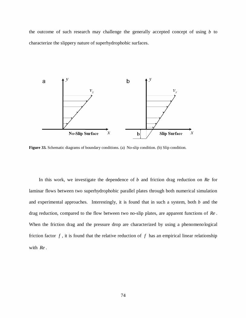
74
the outcome of such research may challenge the generally accepted concept of using b to
characterize the slippery nature of superhydrophobic surfaces.
Figure 33. Schematic diagrams of boundary conditions. (a) No-slip condition. (b) Slip condition.
In this work, we investigate the dependence of b and friction drag reduction on Re for
laminar flows between two superhydrophobic parallel plates through both numerical simulation
and experimental approaches. Interestingly, it is found that in such a system, both b and the
drag reduction, compared to the flow between two no-slip plates, are apparent functions of Re .
When the friction drag and the pressure drop are characterized by using a phenomenological
friction factor f , it is found that the relative reduction of f has an empirical linear relationship
with Re .

75
4.2.2 Methodology
For a laminar flow between two infinite parallel plates separated by a distance H , the velocity
profile can be described by (Appendix):
(10) 02
2
,dx
dp
dy
vd x
where x is along the flow direction, is the viscosity of the fluid. With the no-slip boundary
condition, i.e., at 2/Hy , 0xv , the pressure gradient along the flow direction is:
(11) 6
3
2
,H
Re
dx
dp
slipno
where is the density of fluid, and hUDRe with U being the average velocity. This
pressure gradient can also be described by using a phenomenological friction factor f by Darcy-
Weisbach equation [79]:
,2U
D
dx
dpf h
slipno
slipno
(12)
where hD is the hydraulic diameter (here HDh 2 ). For a laminar flow between two infinite
parallel plates with no-slip boundary conditions, the friction factor Ref slipno 96 [79].
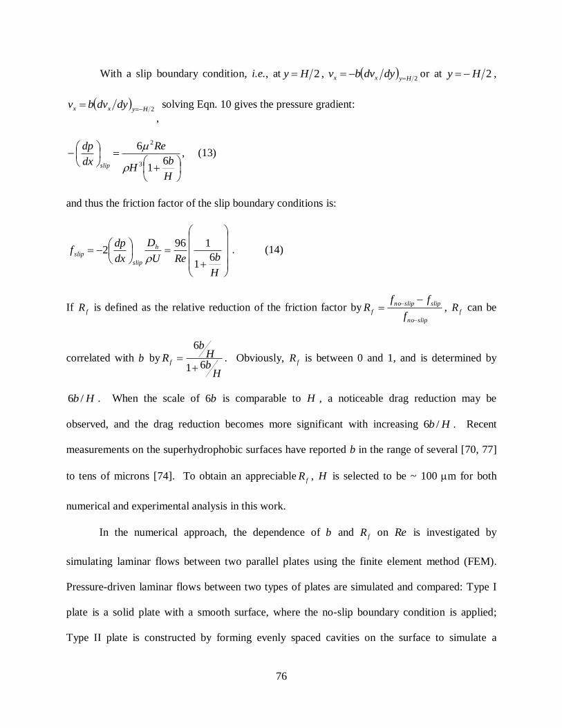
76
With a slip boundary condition, i.e., at 2Hy , 2Hyxx dydvbv
or at 2Hy ,
2Hyxx dydvbv
,
solving Eqn. 10 gives the pressure gradient:
,6
1
6
3
2
H
bH
Re
dx
dp
slip
(13)
and thus the friction factor of the slip boundary conditions is:
H
bReU
D
dx
dpf h
slip
slip 61
1962
. (14)
If fR is defined as the relative reduction of the friction factor byslipno
slipslipno
ff
ffR
, fR can be
correlated with b by
HbH
b
R f 61
6
. Obviously, fR is between 0 and 1, and is determined by
Hb /6 . When the scale of b6 is comparable to H , a noticeable drag reduction may be
observed, and the drag reduction becomes more significant with increasing Hb /6 . Recent
measurements on the superhydrophobic surfaces have reported b in the range of several [70, 77]
to tens of microns [74]. To obtain an appreciable fR , H is selected to be ~ 100 m for both
numerical and experimental analysis in this work.
In the numerical approach, the dependence of b and fR on Re is investigated by
simulating laminar flows between two parallel plates using the finite element method (FEM).
Pressure-driven laminar flows between two types of plates are simulated and compared: Type I
plate is a solid plate with a smooth surface, where the no-slip boundary condition is applied;
Type II plate is constructed by forming evenly spaced cavities on the surface to simulate a
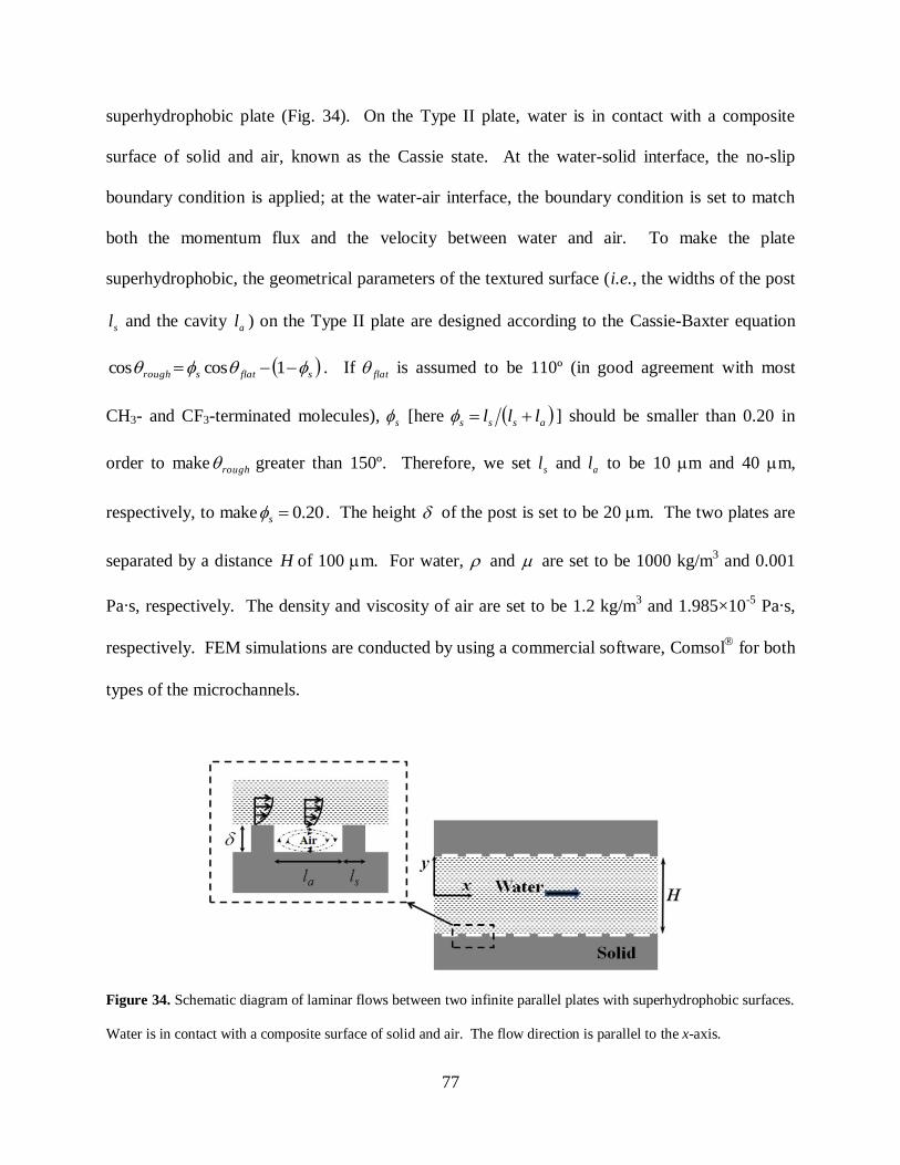
77
superhydrophobic plate (Fig. 34). On the Type II plate, water is in contact with a composite
surface of solid and air, known as the Cassie state. At the water-solid interface, the no-slip
boundary condition is applied; at the water-air interface, the boundary condition is set to match
both the momentum flux and the velocity between water and air. To make the plate
superhydrophobic, the geometrical parameters of the textured surface (i.e., the widths of the post
sl and the cavity al ) on the Type II plate are designed according to the Cassie-Baxter equation
sflatsrough 1coscos . If flat is assumed to be 110º (in good agreement with most
CH3- and CF3-terminated molecules), s [here asss lll ] should be smaller than 0.20 in
order to make rough greater than 150º. Therefore, we set sl and al to be 10 m and 40 m,
respectively, to make 20.0s . The height of the post is set to be 20 m. The two plates are
separated by a distance H of 100 m. For water, and are set to be 1000 kg/m3 and 0.001
Pa∙s, respectively. The density and viscosity of air are set to be 1.2 kg/m3 and 1.985×10
-5 Pa∙s,
respectively. FEM simulations are conducted by using a commercial software, Comsol
for both
types of the microchannels.
Figure 34. Schematic diagram of laminar flows between two infinite parallel plates with superhydrophobic surfaces.
Water is in contact with a composite surface of solid and air. The flow direction is parallel to the x-axis.

78
In the experimental approach, the dependence of b and fR on Re is investigated by
posing laminar flows in a channel formed between two superhydrophobic plates and measuring
the pressure drop along the flow. The channel is fabricated by machining a 100 m deep groove
on an aluminum (Al) plate, and covering the Al plate with a polydimethylsiloxane (PDMS)
membrane, as schematically shown in Figs. 35a and b. The length L , height H and width W of
the channel are 10 cm, 100 m and 5 mm, respectively. Since W is far greater than H , the
channel is a good approximation to the model of two infinite parallel plates. The PDMS
membrane has 4 openings, and each opening is connected to a silicone tubing sealed by the
epoxy resin. The 4 tubings are used to connect the channel to the pump and the pressure gauge.
During the experiments, the PDMS membrane is tightly sealed with the Al plate by another
covering Al plate with a rectangular opening. An infusion pump (Harvard Apparatus, Model
PHD 2000) is used to drive the flow through the channel. A wet/wet differential pressure gauge
(Omega PX26) is used to measure the pressure drop p along a fixed distance L (5cm). The
distance eL (2cm) between the inlet opening and the upstream opening for the pressure
measurement is much larger than the entrance length (~ ReDh06.0 ) of the flow. To make the Al
plate and the PDMS membrane surface superhydrophobic, a nanoparticle-polymer composite
[80] is applied on both substrates. Figure 35c shows the SEM image of the composite. The water
contact angle on the coating is ~165o (Fig. 35d). After measurement is completed using the
superhydrophobic channel, the superhydrophobicity of the coating is removed by applying an
O2-plasma treatment (South Bay Technology model PC-2000 RF Plasma Cleaning System), and
both the top and bottom plates become hydrophilic without apparent morphological change on
the surface.
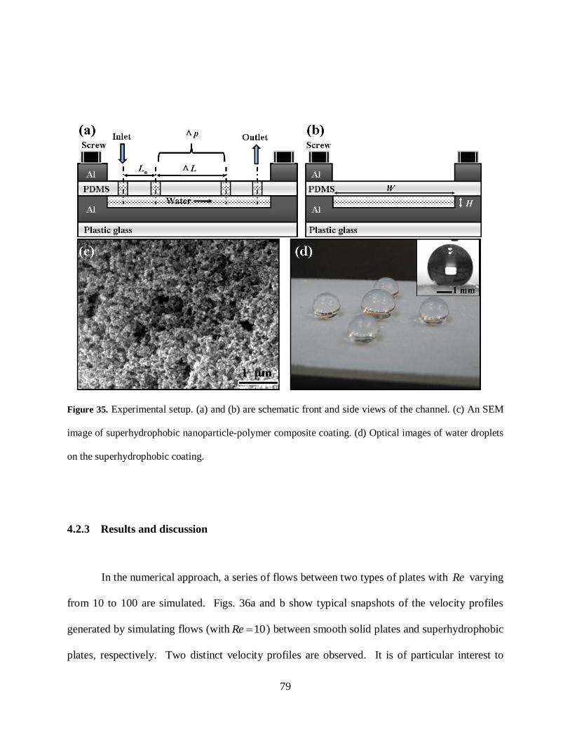
79
Figure 35. Experimental setup. (a) and (b) are schematic front and side views of the channel. (c) An SEM
image of superhydrophobic nanoparticle-polymer composite coating. (d) Optical images of water droplets
on the superhydrophobic coating.
4.2.3 Results and discussion
In the numerical approach, a series of flows between two types of plates with Re varying
from 10 to 100 are simulated. Figs. 36a and b show typical snapshots of the velocity profiles
generated by simulating flows (with 10Re ) between smooth solid plates and superhydrophobic
plates, respectively. Two distinct velocity profiles are observed. It is of particular interest to
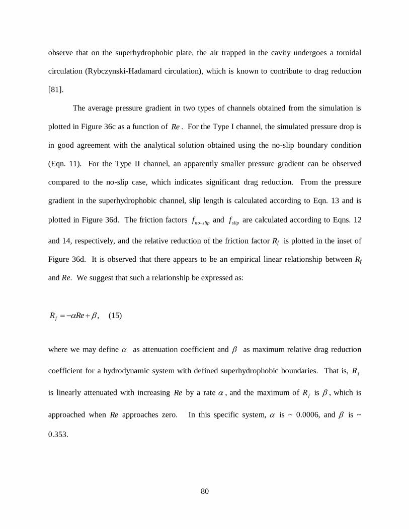
80
observe that on the superhydrophobic plate, the air trapped in the cavity undergoes a toroidal
circulation (Rybczynski-Hadamard circulation), which is known to contribute to drag reduction
[81].
The average pressure gradient in two types of channels obtained from the simulation is
plotted in Figure 36c as a function of Re . For the Type I channel, the simulated pressure drop is
in good agreement with the analytical solution obtained using the no-slip boundary condition
(Eqn. 11). For the Type II channel, an apparently smaller pressure gradient can be observed
compared to the no-slip case, which indicates significant drag reduction. From the pressure
gradient in the superhydrophobic channel, slip length is calculated according to Eqn. 13 and is
plotted in Figure 36d. The friction factors slipnof and slipf are calculated according to Eqns. 12
and 14, respectively, and the relative reduction of the friction factor Rf is plotted in the inset of
Figure 36d. It is observed that there appears to be an empirical linear relationship between Rf
and Re. We suggest that such a relationship be expressed as:
, ReR f (15)
where we may define as attenuation coefficient and as maximum relative drag reduction
coefficient for a hydrodynamic system with defined superhydrophobic boundaries. That is, fR
is linearly attenuated with increasing Re by a rate and the maximum of fR is which is
approached when Re approaches zero. In this specific system, is ~ 0.0006, and is ~
0.353.
81
Figure 36. Simulation results. (a) and (b) are snapshots of the velocity profiles generated by simulating laminar
flows (with Re = 10) in two types of channels formed between smooth solid plates and superhydrophobic plates,
respectively. (c) Pressure gradient in two types of channels as a function of Re. The solid line is the analytical
solution. (d) Slip length and the relative reduction of the friction factor Rf (inset) as a function of Re.
For the experimental results, Figure 37a shows the average pressure gradient measured as
a function of Re . When the plates are hydrophilic (i.e., with no-slip boundary conditions), the
measured pressure gradient is in good agreement with the analytical solution. When the plates
are superhydrophobic, the pressure gradient is apparently reduced, indicating interfacial slip on
the superhydrophobic surface. From the pressure gradient, b and fR are calculated and plotted
in Figure 37b as a function of Re . Similar to the result obtained by numerical simulation, an
approximate linear relationship is also obtained between fR and Re through the experimental
82
approach. If fR is written as a function of Re in the form of Eqn. 15, is ~0.0012, which is
greater than the obtained by the numerical simulation, and is ~ 0.212, which is smaller
than the obtained by the numerical simulation. This indicates that the influence of Re on the
interfacial slip is stronger for the experimental system than for the simulation system, but the
maximum fR and b is smaller in the experimental system than in the simulation system. The
reason for such a result may be attributed to the difference in various intrinsic surface properties
(such as surface textures) between the plates used in experiments and in simulation. Although
how and may be affected by the surface texture of a superhydrophobic surface is still
unknown, our result clearly indicates that the slippery nature of a superhydrophobic surface
would be more properly characterized by using and than by using b.
4.2.4 Conclusion
We have investigated interfacial slip on superhydrophobic surfaces and the resulting
hydrodynamic drag reduction of laminar flows between two parallel plates through both
numerical simulation and experimental approaches. Up to 20%-30% reduction in the friction
factor has been observed by either approach. It has been observed that slip length, a parameter
commonly used to characterize the slippery nature of superhydrophobic surfaces, significantly
decreases with increasing Re . When the drag reduction is described by the relative reduction of
the friction factor fR , it is found that fR has an empirical linear dependence on Re . We
suggest that such a linear relationship be described by two phenomenological coefficients—
attenuation coefficient and maximum relative drag reduction coefficient—for a hydrodynamic
system with defined superhydrophobic boundaries. Such a linear relationship may provide a

83
convenient approach for calculating friction drag in hydrodynamic systems involving
superhydrophobic surfaces.
Figure 37. Data obtained from experimental results: (a) pressure drop measurements as a function of Re;
(b) the influence of Re on the slip length as well as the drag reduction (inset).
84
5.0 SUMMARY
This dissertation consists of two major sections: the first section (1.0-3.0) focuses on the design
and fabrication of superhydrophobic surfaces, and the second section focuses on the application
(4.0) of such surfaces. In the first section, on the basis of a review of general principles and
experimental methods for fabricating superhydrophobic surfaces, we introduce a novel design
concept and develop practical schemes, which typically involve nanomaterial synthesis as well
as micro- and nano-fabrication technologies, for making superhydrophobic surfaces on
intrinsically hydrophilic materials. This design concept and the experimental methods for
implementing it have also been employed to make superoleophobic surfaces that repel oil in the
same way as superhydrophobic surfaces repel water. In the second section, we present our initial
effort to explore two promising applications of superhydrophobic surfaces: one is to prevent
supercooled water from icing; the other is to reduce friction drag of internal water flows. The
primary accomplishments of the research outlined in this paper can be summarized as the
following:
1. We have developed a general design principle for fabricating surfaces with special
surface topographical textures (e.g., overhang or re-entrant curvature) that may induce the
superhydrophobic and/or superoleophobic phenomena on intrinsically hydrophilic and/or
oleophilic substrates.
85
2. We have experimentally proved our design principle by fabricating Si micro-textures
with well-defined overhang structures in both micrometer and nanometer scales, which
are able to induce a superhydrophobic behavior on hydrophilic H-terminated silicon
surfaces with a flat of ~ 74º.
3. We have demonstrated that our design principle can be applied to fabricate non-aging
superhydrophobic surfaces by packing flower-like hematite particles. These
superhydrophobic surfaces do not age even in extremely oxidative environments—they
are able to retain the superhydrophobicity after being stored in ambient laboratory air for
4 months, heated to 800ºC in air for 10 hours, and exposed to ultraviolet ozone for 10
hours.
4. We have demonstrated that our design principle can be extended to fabricate super oil-
repellent surfaces on intrinsically oleophilic substrates using porous Si films as an
example. The porous Si films are fabricated by a gold-assisted electroless etching
process, which produces a hierarchical porous structure that consists of micrometer-sized
asperities superimposed onto a network of nanometer-sized pores. Contact angles of
greater than 150° for both diethylene glycol and hexadecane have been obtained on
porous Si surfaces after surface treatment.
5. We have demonstrated that a transparent superhydrophobic and highly oleophobic
coating can be fabricated based on a porous network of nanoparticles by using a layer-by-
layer assembly technique. The resulting nanoporous structure is highly transparent and
can be made both superhydrophobic and highly oleophobic after functionalization with a
fluorocarbon molecule. We believe that the nanoporous textures form overhang
structures on the coating surface, which induce the high oil-repellency of the coating even

86
though the intrinsic oil contact angle of the solid surface is less than 90°. Although
transparent superhydrophobic coatings have been demonstrated using the layer-by-layer
assembly technique previously, to the best of our knowledge, this is the first
demonstration of fabricating transparent coatings that are both superhydrophobic and
highly oleophobic.
6. We have used nanoparticle-polymer composites to demonstrate the anti-icing capability
of superhydrophobic surfaces and report direct experimental evidence that such surfaces
are able to prevent ice formation upon impact of supercooled water both in laboratory
conditions and in natural environments. We find that the anti-icing capability of these
composites depends not only on their superhydrophobicity but also on the size of the
particles exposed on the surface. The critical particle sizes that determine the
superhydrophobicity and the anti-icing property are in two different length scales. The
effect of particle size on ice formation is explained by using a classical heterogeneous
nucleation theory. This result implies that the anti-icing property of a surface is not
directly correlated with the superhydrophobicity, and thus it is uncertain whether a
superhydrophobic surface is anti-icing without detailed knowledge of the surface
morphology. The result also opens up possibilities for rational design of anti-icing
superhydrophobic surfaces by tuning surface textures in multiple length scales.
7. We have investigated interfacial slip on superhydrophobic surfaces and the resulting
hydrodynamic drag reduction of laminar flows between two parallel plates through both
numerical simulation and experimental approaches. It shows that slip length, a parameter
commonly used to characterize the slippery nature of superhydrophobic surfaces,
significantly decreases when the Reynolds number Re of laminar flows posed between

87
two superhydrophobic plates increases. When the resulting hydrodynamic drag reduction
is described by the relative reduction fR of a phenomenological friction factor, it is
found that fR has an empirical linear dependence on Re . Such a linear relationship may
provide a convenient approach for calculating friction drag in hydrodynamic systems
involving superhydrophobic surfaces.

88
APPENDIX
LAMINAR FLOW BETWEEN TWO INFINITE PARALLEL PLATES
Under an incompressible flow assumption for Newtonian fluids with constant and the
typical Navier-Stokes equation is
gvpvvt
v
2 , (A1)
where and are the density and viscosity of the liquid, respectively, and p is the pressure.
When a Newtonian fluid flows through two infinite parallel plates separated by a distance
H, and the pressure drop is along x direction, Eqn.A1 may be expressed in the Cartesian
coordinates (x, y, z) as
2 2 2
2 2 2
x x x x x x xx y z x
v v v v v v vpv v v g
t x y z x x y z
. (A2)
Because )(yvv xx , p=p(x) and gx=0, Eqn. A2 can be simplified to
2
2
0dy
vd
dx
dp x . (A3)
It may be integrated to give
1Cdx
dpy
dy
dvx
. (A4)

89
B.C. 1: at y=0, finitedy
dvx
Consequently C1 must be zero. Therefore, the shear rate distribution is
dx
dpy
dy
dvx
. (A5)
This first-order separable differential equation may be integrated to give
2
2
2C
dx
dpyvx
. (A6)
In the case of no-slip boundary condition,
B.C. 2: at 2Hy , vx=0
From this, the C2 is found to be2
8no slip
Hdp
dx
. Hence the velocity distribution is
22 48
1yH
dx
dpv
slipno
x
. (A7)
The average velocity U can be calculated from Eqn. A7
slipno
H
x
dx
dpH
H
dyvU
12
2 22
0 . (A8)
From Eqn. A 8,
3
2
2
612
H
Re
H
U
dx
dp
slipno
, (A9)

90
where
hUDRe is the Reynolds number based on the hydraulic diameter (Dh is dependent on
the cross sectional area, A, and the perimeter of the channel, P, by PADh 4 . For the flow
between the two infinite parallel plates, the channel height H is finite, while the channel width W
is infinite. As a consequence, HWHHWDh 2)()(2 ), average velocity U, and kinematic
viscosity ( / ). The Darcy friction factor ( f ) for laminar flow can be calculated by Eqns
A8 and A9:
,ReU
D
dx
dpf h
slipno
slipno
962
(A10)
However, when the interfacial slip occurs at the channel surface, the boundary conditions
change to:
B.C. 2: at 2Hy , 2Hy
xx
dy
dvbv
or 2Hy ,
2Hy
xx
dy
dvbv
where b is defined as slip length, and slipHy
x
Hy
x
dx
dpH
dy
dv
dy
dv
2
22
calculated from
Eqn A5.
From this new boundary condition, the C2 in Eqn A6 can be found to
be21
2 4slip
dp HbH
dx
. Hence the velocity distribution is
22 448
1yHbH
dx
dpv
slip
x
(A11)
The average velocity U can be calculated from Eqn. A11
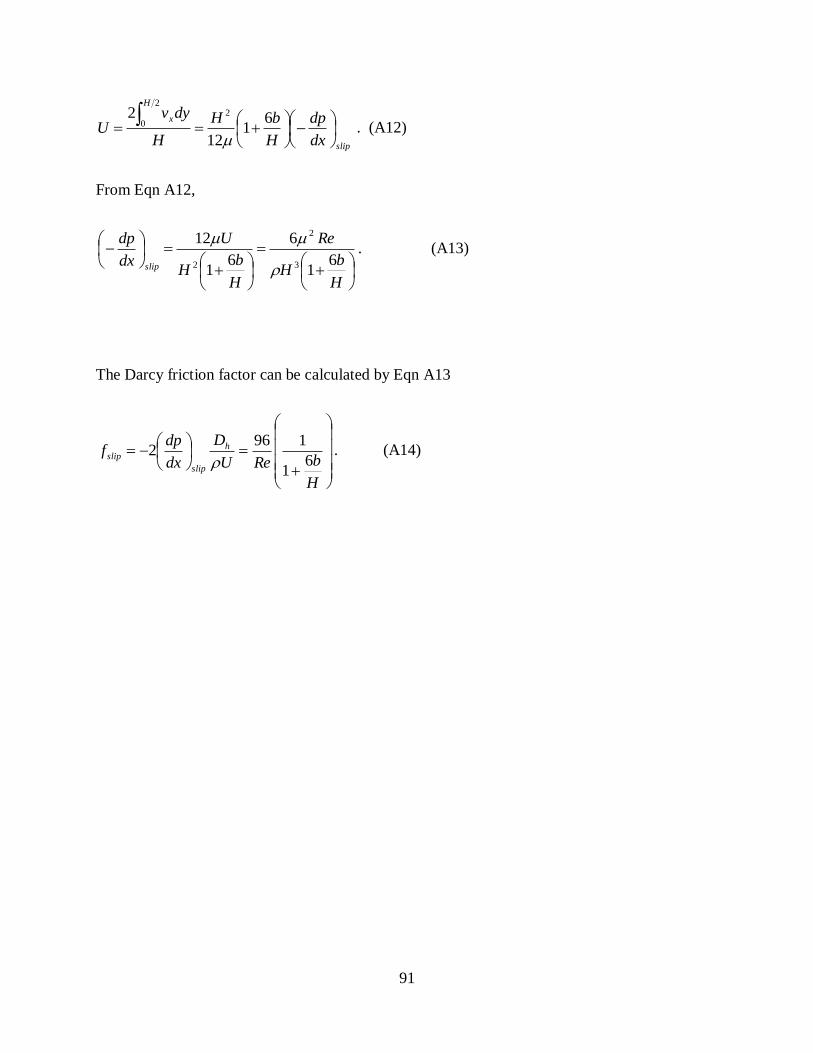
91
slip
H
x
dx
dp
H
bH
H
dyvU
61
12
2 22
0
. (A12)
From Eqn A12,
H
bH
Re
H
bH
U
dx
dp
slip6
1
6
61
12
3
2
2
. (A13)
The Darcy friction factor can be calculated by Eqn A13
H
bReU
D
dx
dpf h
slip
slip 61
1962
. (A14)

92
BIBLIOGRAPHY
1. R. Blossey, Self-cleaning surfaces- virtual realities. Nature Mater. 2003, 2, 301-306.
2. L. Feng, S. Li, Y. Li, H. Li, L. Zhang, J. Zhai, Y. Song, B. Liu, L. Jiang, and D. Zhu, Super-
hydrophobic surfaces: From natural to artificial. Adv. Mater. 2002, 14, 1857-1860.
3. R. Furstner, W. Barthlott, C. Neinhuis and P. Walzel, Wetting and Self-cleaning Properties of
Artificial Superhydrophobic surfaces. Langmuir 2005, 21, 956-961.
4. X. F. Gao, and L. Jiang, Water-repellent legs of water striders. Nature 2004, 432, 36-36.
5. W. Lee, M.K. Jin, W.C. Yoo, and J. K. Lee, Nanostructuring of a polymeric substrate with
well-defined nanometer-scale topography and tailored surface wettability. Langmuir 2004,
20, 7665-7669.
6. J. N. Israelachvili, Intermolecular and Surface Forces, 2nd
ed.; Academic Press: New York,
1991; pp 144-145.
7. S. Shibuichi, T. Yamamoto, T. Onda, and K. Tsujii, Super water- and oil-repellent surfaces
resulting from fractal structure. J. Colloid Interface Sci.1998, 208, 287-294.
8. R.N. Wenzel, Resistance of solid surfaces to wetting by water. Ind. Eng. Chem. 1936, 28,
988-994.
9. A.B.D. Cassie, and S. Baxter, Wettability of porous surfaces. Trans. Faraday Soc. 1944, 40,
546-551.
10. D. Quéré, Non-sticking drops. Rep. Prog. Phys. 2005, 68, 2495-2532.
11. J. Bico, U. Thiele, and D. Quéré, Wetting of textured surfaces. Colloids Surf. A 2002, 206,
41-46.
12. C.G.L. Furmidge, Studies at phase interfaces. I. The sliding of liquid drops on solid surfaces
and a theory for spray retention. J. Colloid Sci. 1962, 17, 309-324.
13. T. Onda, S. Shibuichi, N. Satoh, and K. Tsujii, Super-Water-Repellent Fractal Surfaces.
Langmuir 1996, 12, 2125-2127.

93
14. M. Jin, X. Feng, J. Xin, J. Zhai, K. Cho, L. Feng, and L. Jiang, Super-hydrophobic PDMS
surface with ultra-low adhesive force. Macromol. Rapid Commun. 2005, 26, 1805-1809.
15. M. Ma, R. M. Hill, J. L. Lowery, S. V. Fridrikh, and G. C. Rutledge, Electrospun
poly(styrene-block-dimethylsiloxane) block copolymer fibers exhibiting superhydrophobicity.
Langmuir 2005, 21, 5549-5554.
16. H. Y. Erbil, A. L. Demirel, Y. Avci, and O. Mert, Transformation of a simple plastic into a
superhydrophobic surface. Science 2003, 299, 1377-1380.
17. L. Zhang, Z. Zhou, B. Cheng, J. M. DeSimone, and E. T. Samulski, Superhydrophobic
behavior of a perfluoropolyether lotus-leaf-like topography. Langmuir 2006, 22, 8576-8580.
18. H. Yan, K. Kurogi, H. Mayama, and K. Tsujii, Environmentally stable super water-repellent
poly(alkylpyrrole) films. Angew. Chem. Int. Ed. 2005, 44,3453-3456.
19. X. Feng, L. Feng, M. Jin, J. Zhai, L. Jiang, and D. Zhu, Reversible superhydrophobicity to
superhydrophilicity transition of aligned ZnO nanorod films. J. Am. Chem. Soc. 2004, 126,
62-63.
20. X. Feng, J. Zhai, and L. Jiang, The fabrication and switchable superhydrophobicity of TiO2
nanorod films. Angew. Chem. Int. Ed. 2005, 44, 5115-5118.
21. D. Oner, and T. J. McCarthy, Ultrahydrophobic surfaces. Effects of topography length scales
on wettability. Langmuir 2000, 16, 7777-7782.
22. T. Baldacchini, J. E. Carey, M. Zhou, and E. Mazur, Superhydrophobic surfaces prepared by
microstructuring of silicon using a femtosecond laser. Langmuir 2006, 22, 4917-4919.
23. N. Verplanck, E. Galopin, J. Camart, and V. Thomy, Reversible electrowetting on
superhydrophobic silicon nanowires. Nano lett. 2007, 7, 813-817.
24. B. Qian, and Z. Shen, Fabrication of superhydrophobic surfaces by dislocation-selective
chemical etching on aluminum, copper, and zinc substrates. Langmuir 2005, 21, 9007-9009.
25. X. Zhang, F. Shi, X. Yu, H. Liu, Y. Fu, Z. Wang, L. Jiang, and X. Li, Polyelectrolyte
multilayer as matrix for electrochemical deposition of gold clusters: toward
superhydrophobic surface. J. Am. Chem. Soc. 2004, 126, 3064-3065.
26. N. Zhao, F. Shi, Z. Wang, and X. Zhang, Combining layer-by-layer assembly with
electrodeposition of silver aggregates for fabricating superhydrophobic surfaces. Langmuir
2005, 21, 4713-4716.
27. K. Tsujii, T. Yamamoto, T. Onda, and S. Shibuichi, Super oil-repellent surfaces. Angew.
Chem., Int. Ed. Engl. 1997, 36, 1011-1012.
28. S. Shibuichi, T. Yamamoto, T. Onda, and K. Tsujii, Super water- and oil-repellent surfaces
resulting from fractal structure. J. Colloid Interface Sci. 1998, 208, 287-294.
94
29. C. Neinhuis, and W. Barthlott, Characterization and distribution of water-repellent, self-
cleaning plant surfaces. Ann. Bot. 1997, 79, 667-667.
30. Y. T. Cheng, and D. E. Rodak, Is the lotus leaf superhydrophobic? Appl. Phys. Lett. 2005, 86,
144101.
31. http://www.surface-tension.de/
32. A. Lafuma, and D. Quéré, Superhydrophobic states. Nature Mater. 2003, 2, 457-460.
33. A. Marmur, The lotus effect:superhydrophobicity and metastability. Langmuir 2004, 20,
3517-3519.
34. B. He, N. A. Patankar, and J. Lee, Multiple equilibrium droplet shapes and design criterion
for rough hydrophobic surfaces. Langmuir 2003, 19, 4999-5003.
35. C. Ishino, K. Okumura, and D. Quéré, Wetting transitions on rough surfaces. Europhys Lett.
2004, 68, 419-425.
36. S. Herminghaus, Roughness-induced non-wetting. Europhys. Lett. 2000, 52, 165-170.
37. J. Westwater, D. P. Gosain, S. Tomiya, S. Usui, and H. Ruda, Growth silicon nanowires via
gold/silane vapor-liquid-solid reaction. J. Vac. Sci. Technol. B 1997, 15, 554.
38. D. Gao, R. He, C. Carraro, R. T. howe, P. Yang, and R. Maboudian, Selective growth of Si
nanowire arrays via galvanic displacement processes in water-in-oil microemulsions. J. Am.
Chem. Soc. 2005, 127, 4574-4575.
39. M. R. Houston, and R. Maboudian, Stability of ammonium fluoride-treated Si (100). J. Appl.
Phys. 1995, 78, 3801-3808.
40. A. Tuteja, W. Choi, M. Ma, J. M. Mabry, S. A. Mazzella, G. C. Rutledge, G. H. McKinley,
and R. E. Cohen, Designing superoleophobic surfaces. Science 2007, 318, 1618-1622.
41. L. Zhong, J. Hu, H. Liang, A. Cao, W. Song, and L. Wan, Self-assembled 3D flowerlike iron
oxide nanostructures and their application in water treatment. Adv. Mat. 2006, 18, 2426-2431.
42. S. M. Iveson, S. Holt, and S. Biggs, Advancing contact angle of iron ores as a function of
their hematite and goethite content: implications for pelletising and sintering. Int. J. Miner.
Process. 2004, 74, 281-287.
43. Y. Li, Y. Bando, and D. Golberg, MoS2 nanoflowers and their field-emission properties. Appl.
Phys. Lett. 2003, 82, 1962-1964.
44. Y. Zhao, D. Ye, G. Wang, and T. Lu, Novel nano-column and nano-flower arrays by
glancing angle deposition. Nano. Lett. 2002, 2, 351-354.

95
45. Z. Wang, X. F. Qian, J. Yin, and Z. Zhu, Large-scale fabrication of tower-like, flower-like,
and tube-like ZnO arrays by a simple chemical solution route. Langmuir 2004, 20, 3441-
3448.
46. K. Peng, J. Hu, Y. Yan, Y. Wu, H. Fang, Y. Xu, S. Lee, and J. Zhu, Fabrication of single-
crystalline silicon nanowires by scratching a silicon surface with catalytic metal particles.
Adv. Funct. Mater. 2006, 16, 387-394.
47. J. Bravo, L. Zhai, Z. Wu, R. E. Cohen, and M. F. Rubner, Transparent superhydrophobic
films based on silica nanoparticles, Langmuir 2007, 23, 7293-7298.
48. Y. Li, F. Liu, and J. Sun, A facile layer-by-layer deposition process for the fabrication of
highly transparent superhydrophobic coatings. Chem. Commun. 2009, 23, 2730-2732.
49. Y. H. Xiu, F. Xiao, D. W. Hess, and C. P. Wong, Superhydrophobic optically transparent
silica films formed with a eutectic liquid. Thin Solid Films 2009, 517, 1610-1615.
50. G. R. J. Artus, S. Jung, J. Zimmermann, H. –P. Gautschi, K. Marquardt, and S. Seeger,
Silicone nanofilaments and their application as superhydrophobic coatings. Adv. Mater. 2006,
18, 2758-2762.
51. L. Cao, T. P. Price, M. Weiss, and D. Gao, Super water- and oil-repellent surfaces on
intrinsically hydrophilic and oleophilic porous silicon films. Langmuir 2008, 24, 1640-1643.
52. L. Cao, H. Hu, and D. Gao, Design and fabrication of micro-textures for inducing a
superhydrophobic behavior on hydrophilic materials. Langmuir 2007, 23, 4310-4314.
53. A. Cao, L. Cao, and D. Gao, Fabrication of nonaging superhydrophobic surfaces by packing
flowerlike hematite particles. Appl. Phys. Lett. 2007, 91, 034102.
54. H. Saito, K. Takai, and G. Yamauchi, Water- and ice-repellent coatings. Surf. Coat. Int. 1997,
80, 168-171.
55. A. Nakajima, K. Hashimoto, and T. Watanabe, Recent studies on super-hydrophobic films.
Monatsh. Chem. 2001, 132, 31-41.
56. S.A. Kulinich, and M. Farzaneh, Ice adhesion on super-hydrophobic surfaces. Appl. Surf. Sci.
2009, 255, 8153-6157.
57. S. G. Cober, G. A. Isaac, and J. W. Strapp, Characterizations of aircraft icing environments
that include supercooled large drops. J. Appl. Meteorol. 2001, 40, 1984-2002.
58. S. Lasher-Trapp, S. Anderson-Bereznicki, A. Shackelford, C. H. Twohy, and J. G. Hudson,
An investigation of the influence of droplet number concentration and giant aerosol particles
upon supercooled large drop formation in wintertime stratiform clouds. J. Clim. Appl.
Meteorol. 2008, 47, 2659-2678.
96
59. X. Liu, A new kinetic model for three-dimensional heterogeneous nucleation. J. Chem. Phys.
1999,111, 1628-1635.
60. W. M. Ketcham, and P. V. Hobbs, An experimental determination of surface energies of ice.
Philos. Mag. 1969, 19, 1161-1173.
61. C. Neto, D. R. Evans, E. Bonaccurso, H. J. Butt, and V. S. J. Craig, Boundary slip in
Newtonian liquids: a review of experimental studies. Rep. Prog. Phys. 2005, 68, 2859-2897.
62. O. I. Vinogradova, Drainage of a thin liquid-film confined between hydrophobic surfaces.
Langmuir 1995, 11, 2213-2220.
63. O. I. Vinogradova, Slippage of water over hydrophobic surfaces. Int. J. Miner. Process 1999,
56, 31-60.
64. P. G. de Gennes, On fluid/wall slippage. Langmuir 2002, 18, 3413-3414.
65. Y. Zhu, and S. Granick, Rate-dependent slip of Newtonian liquid at smooth surfaces. Phys.
Rev. Lett. 2001, 87, 096105.
66. S. Granick, Y. Zhu, and H. Lee, Slippery questions about complex fluids flowing past solids.
Nat. Mater. 2003, 2, 221-227.
67. D. C. Tretheway, and C. D. Meinhart, A generating mechanism for apparent fluid slip in
hydrophobic microchannels. Phys. Fluids 2004, 16, 1509-1515.
68. K. Watanabe, Y. Udagawa, and H. Udagawa, Drag reduction of Newtonian fluid in a circular
pipe with a highly water-repellent wall. J. Fluid Mech. 1999, 381, 225-238.
69. K. Watanabe, T. Takayama, S. Ogata, and S. Isozaki, Flow between two coaxial rotating
cylinders with a highly water-repellent wall. AIChE J. 2003, 49, 1956-1963.
70. J. Ou, J. B. Petrot, and J. P. Rothstein, Laminar drag reduction in microchannels using
ultrahydrophobic surfaces. Phys. Fluids 2004, 16, 4635-4643.
71. N. J. Shirtcliffe, G. McHale, M. I. Newton, and Y. Zhang, Superhydrophobic copper tubes
with possible flow enhancement and drag reduction. ACS Appl. Mater. Interface 2009, 1,
1316-1323.
72. S. Gogte, P. Vorobieff, R. Truesdell, A. Mammoli, F. van Swol, P. Shah, and C. J. Brinker,
Effective slip on textured superhydrophobic surfaces. Phys. Fluids 2005, 17, 051701.
73. R. Truesdell, A. Mammoli, P. Vorobieff, F. van Swol, and C. J. Brinker, Drag reduction on a
patterned superhydrophobic surface. Phys. Rev. Lett. 2006, 97, 044504.
74. C. H. Choi, and C. J. Kim, Large slip of aqueous liquid flow over a nanoengineered
superhydrophobic surface. Phys. Rev. Lett. 2006, 96, 066001.

97
75. C. H. Choi, U. Ulmanella, J. Kim, C. M. Ho, and C. J. Kim, Effective slip and friction
reduction in nanograted superhydrophobic microchannels. Phys. Fluids 2006, 18, 087105.
76. C. Navier, Memoire sur les lois du movement des fluids. Memoires de l’ Academie Royale
des Sciences de l’Institut de France 1823, 6, 389-416.
77. P. Joseph, C. Cottin-Bizonne, J. M. Benoit, C. Ybert, C. Journet, P. Tabeling, and L.
Bocquet, Slippage of water past superhydrophobic carbon nanotube forests in microchannels.
Phys. Rev. Lett. 2006, 97, 156104.
78. C. Lee, C. H. Choi, and C. J. Kim, Structured surfaces for a giant liquid slip. Phys. Rev. Lett.
2008, 101, 064501.
79. R. D. Blevins, Applied Fluid Dynamics Handbook (Van Nostrand Reinhold, New York,
1984).
80. L. Cao, A. K. Jones, V. K. Sikka, J. Wu, and D. Gao, Anti-icing superhydrophobic coatings,
Langmuir 2009, 25, 12444-12448.
81. S. S. Sadhal, P. S. Ayyaswamy, and J. N. Chung, Transport phenomena with drops and
bubbles (Springer Verlag, 1997)