superhydrophobic and omnidirectional antire ective ...4unano.com/bg/papers/bayindir group -...
TRANSCRIPT

Superhydrophobic and Omnidirectional Antireflective Surfaces fromNanostructured Ormosil ColloidsAdem Yildirim,†,‡ Tural Khudiyev,†,‡ Bihter Daglar,†,‡ Hulya Budunoglu,†,‡ Ali K. Okyay,†,‡,§
and Mehmet Bayindir†,‡,∥,*†UNAM-National Nanotechnology Research Center, ‡Institute of Materials Science and Nanotechnology, §Department of Electricaland Electronics Engineering, and ∥Department of Physics, Bilkent University, 06800 Ankara, Turkey
*S Supporting Information
ABSTRACT: A large-area superhydrophobic and omnidirectional antire-flective nanostructured organically modified silica coating has beendesigned and prepared. The coating mimics the self-cleaning property ofsuperhydrophobic lotus leaves and omnidirectional broad band antire-flectivity of moth compound eyes, simultaneously. Water contact andsliding angles of the coating are around 160° and 10°, respectively. Coatingimproves the transmittance of the glass substrate around 4%, when coatedon a single side of a glass, in visible and near-infrared region at normalincidence angles. At oblique incidence angles (up to 60°) improvement intransmission reaches to around 8%. In addition, coatings are mechanicallystable against impact of water droplets from considerable heights. Webelieve that our inexpensive and durable multifunctional coatings aresuitable for stepping out of the laboratory to practical outdoor applications.
KEYWORDS: superhydrophobic, self-cleaning, organo-modified silica, antireflection, omnidirectional, functional surfaces
■ INTRODUCTION
Several biological organisms have been synthesizing functionalnano- and microstructures in order to obtain desired surfaceproperty.1,2 Well known examples of these functional surfacesinclude self-cleaning surface of lotus leaves3 and antireflectionstructures on moth compound eyes.4 Lotus leaf surfacecomprises of micro-/nano-hierarchical structures, and thetops of these structures are coated with a thin hydrophobicwax layer. Such a hierarchically rough and low energy surfaceprovides stable superhydrophobicity with high water contactangle, small hysteresis, and easy rolling of water droplets awayfrom the surface. This type of superhydrophobicity can beexplained according to the Cassie−Baxter model in which waterdroplets rest on a surface composed of air trapped in themicrogrooves of a rough surface and tops of these micro-structures.5,6 To obtain such a composite interface betweenwater and the surface, it must be roughened conveniently andcoated with low surface free energy materials.7,8 An orderedhexagonal array of subwavelength nipples on moth compoundeyes, on the other hand, results in antireflection over a broadrange of wavelengths by eliminating the destructive interferencebetween air−array and array−surface interfaces.4 Inspired fromsuch biological examples, many successful approaches havebeen developed to prepare functional surfaces with self-cleaningor antireflection property, using lithographic methods,9−13
deposition of micro-/nanoparticles,14−17 phase separation inpolymers,18−20 layer by layer deposition methods,21−23 andsol−gel methods.24−28
On the other hand, an optically transparent surface (e.g.,glass, quartz, and PMMA) that exhibits both self-cleaning andantireflection features would be very beneficial in manyapplications such as solar cells, LEDs, and optical lenses sincesuch highly transparent and water repellent surfaces canimprove the device performance by eliminating the reflectionlosses and also offer low cost maintenance due to the self-cleaning property.29 However, the challenge in preparing suchmultifunctional surfaces is to balance the high surfaceroughness requirement of superhydrophobic coatings with thelow surface roughness requirement of antireflection coatings.30
Therefore, to prepare antireflective and superhydrophobicsurfaces, roughness must be optimized; it must be smallenough to avoid diffuse reflection from the surface and highenough to provide superhydrophobicity. Although some groupshave prepared surfaces combining the superhydrophobicity andhigh light transmission,31−39 there are still several drawbacksthat hinder the practical outdoor applications of suchmultifunctional coatings. First of all, mechanical and thermaldurability, which are essential for outdoor applications, are notsufficient or even not investigated for most of the coatings.Also, among such multifunctional coatings, highly waterrepellent ones generally exhibit antireflection property in anarrow range of wavelengths, or they can even diminish thelight transmission of their substrates especially at low
Received: October 23, 2012Accepted: January 2, 2013Published: January 2, 2013
Research Article
www.acsami.org
© 2013 American Chemical Society 853 dx.doi.org/10.1021/am3024417 | ACS Appl. Mater. Interfaces 2013, 5, 853−860
wavelengths (<500 nm) because of their rough surfaces. On thecontrary, the coatings with high antireflectivity generallydemonstrate poor water repellency, with low water contactangles and high sliding angles. In addition, most of themultifunctional surface fabrication methods are multistep andrequire expensive and sophisticated equipments. To ourknowledge, all of the reported self-cleaning antireflectionsurfaces possess at least one of the above-mentioned drawbacks.Therefore, inexpensive and facile large-area fabrication methodsare still needed for production of robust self-cleaningantireflection surfaces with good water repellency and broad-band (in visible and near-infrared (NIR) region) andomnidirectional (broad range of incidence angles) antireflectiveproperty.In this context, we report the large-area fabrication of self-
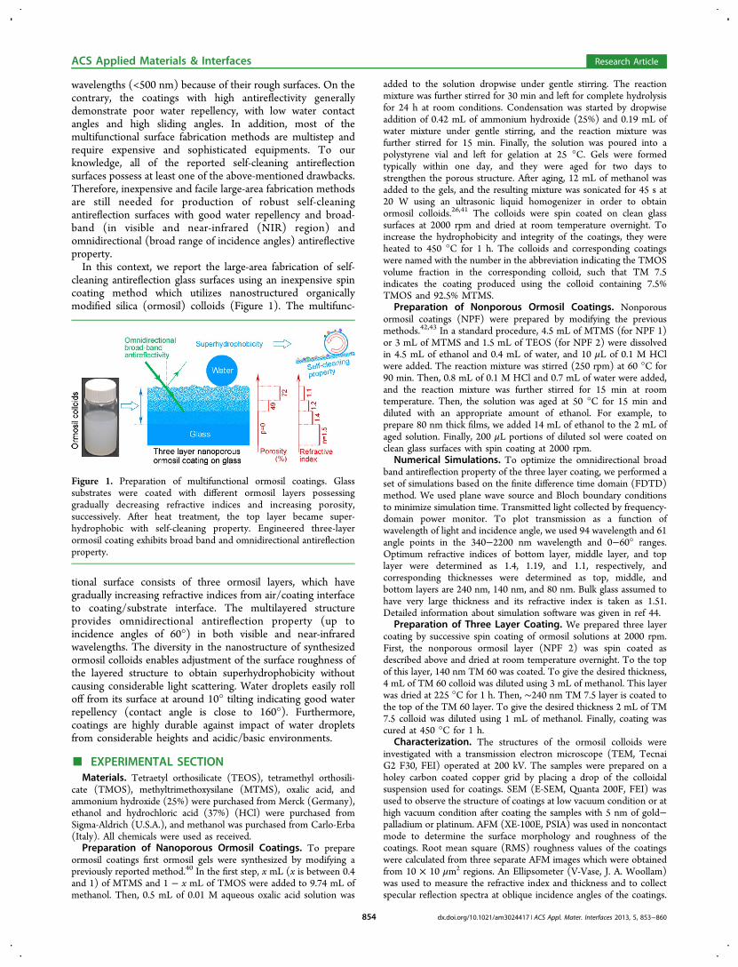
cleaning antireflection glass surfaces using an inexpensive spincoating method which utilizes nanostructured organicallymodified silica (ormosil) colloids (Figure 1). The multifunc-
tional surface consists of three ormosil layers, which havegradually increasing refractive indices from air/coating interfaceto coating/substrate interface. The multilayered structureprovides omnidirectional antireflection property (up toincidence angles of 60°) in both visible and near-infraredwavelengths. The diversity in the nanostructure of synthesizedormosil colloids enables adjustment of the surface roughness ofthe layered structure to obtain superhydrophobicity withoutcausing considerable light scattering. Water droplets easily rolloff from its surface at around 10° tilting indicating good waterrepellency (contact angle is close to 160°). Furthermore,coatings are highly durable against impact of water dropletsfrom considerable heights and acidic/basic environments.
■ EXPERIMENTAL SECTIONMaterials. Tetraetyl orthosilicate (TEOS), tetramethyl orthosili-
cate (TMOS), methyltrimethoxysilane (MTMS), oxalic acid, andammonium hydroxide (25%) were purchased from Merck (Germany),ethanol and hydrochloric acid (37%) (HCl) were purchased fromSigma-Aldrich (U.S.A.), and methanol was purchased from Carlo-Erba(Italy). All chemicals were used as received.Preparation of Nanoporous Ormosil Coatings. To prepare
ormosil coatings first ormosil gels were synthesized by modifying apreviously reported method.40 In the first step, x mL (x is between 0.4and 1) of MTMS and 1 − x mL of TMOS were added to 9.74 mL ofmethanol. Then, 0.5 mL of 0.01 M aqueous oxalic acid solution was
added to the solution dropwise under gentle stirring. The reactionmixture was further stirred for 30 min and left for complete hydrolysisfor 24 h at room conditions. Condensation was started by dropwiseaddition of 0.42 mL of ammonium hydroxide (25%) and 0.19 mL ofwater mixture under gentle stirring, and the reaction mixture wasfurther stirred for 15 min. Finally, the solution was poured into apolystyrene vial and left for gelation at 25 °C. Gels were formedtypically within one day, and they were aged for two days tostrengthen the porous structure. After aging, 12 mL of methanol wasadded to the gels, and the resulting mixture was sonicated for 45 s at20 W using an ultrasonic liquid homogenizer in order to obtainormosil colloids.26,41 The colloids were spin coated on clean glasssurfaces at 2000 rpm and dried at room temperature overnight. Toincrease the hydrophobicity and integrity of the coatings, they wereheated to 450 °C for 1 h. The colloids and corresponding coatingswere named with the number in the abbreviation indicating the TMOSvolume fraction in the corresponding colloid, such that TM 7.5indicates the coating produced using the colloid containing 7.5%TMOS and 92.5% MTMS.
Preparation of Nonporous Ormosil Coatings. Nonporousormosil coatings (NPF) were prepared by modifying the previousmethods.42,43 In a standard procedure, 4.5 mL of MTMS (for NPF 1)or 3 mL of MTMS and 1.5 mL of TEOS (for NPF 2) were dissolvedin 4.5 mL of ethanol and 0.4 mL of water, and 10 μL of 0.1 M HClwere added. The reaction mixture was stirred (250 rpm) at 60 °C for90 min. Then, 0.8 mL of 0.1 M HCl and 0.7 mL of water were added,and the reaction mixture was further stirred for 15 min at roomtemperature. Then, the solution was aged at 50 °C for 15 min anddiluted with an appropriate amount of ethanol. For example, toprepare 80 nm thick films, we added 14 mL of ethanol to the 2 mL ofaged solution. Finally, 200 μL portions of diluted sol were coated onclean glass surfaces with spin coating at 2000 rpm.
Numerical Simulations. To optimize the omnidirectional broadband antireflection property of the three layer coating, we performed aset of simulations based on the finite difference time domain (FDTD)method. We used plane wave source and Bloch boundary conditionsto minimize simulation time. Transmitted light collected by frequency-domain power monitor. To plot transmission as a function ofwavelength of light and incidence angle, we used 94 wavelength and 61angle points in the 340−2200 nm wavelength and 0−60° ranges.Optimum refractive indices of bottom layer, middle layer, and toplayer were determined as 1.4, 1.19, and 1.1, respectively, andcorresponding thicknesses were determined as top, middle, andbottom layers are 240 nm, 140 nm, and 80 nm. Bulk glass assumed tohave very large thickness and its refractive index is taken as 1.51.Detailed information about simulation software was given in ref 44.
Preparation of Three Layer Coating. We prepared three layercoating by successive spin coating of ormosil solutions at 2000 rpm.First, the nonporous ormosil layer (NPF 2) was spin coated asdescribed above and dried at room temperature overnight. To the topof this layer, 140 nm TM 60 was coated. To give the desired thickness,4 mL of TM 60 colloid was diluted using 3 mL of methanol. This layerwas dried at 225 °C for 1 h. Then, ∼240 nm TM 7.5 layer is coated tothe top of the TM 60 layer. To give the desired thickness 2 mL of TM7.5 colloid was diluted using 1 mL of methanol. Finally, coating wascured at 450 °C for 1 h.
Characterization. The structures of the ormosil colloids wereinvestigated with a transmission electron microscope (TEM, TecnaiG2 F30, FEI) operated at 200 kV. The samples were prepared on aholey carbon coated copper grid by placing a drop of the colloidalsuspension used for coatings. SEM (E-SEM, Quanta 200F, FEI) wasused to observe the structure of coatings at low vacuum condition or athigh vacuum condition after coating the samples with 5 nm of gold−palladium or platinum. AFM (XE-100E, PSIA) was used in noncontactmode to determine the surface morphology and roughness of thecoatings. Root mean square (RMS) roughness values of the coatingswere calculated from three separate AFM images which were obtainedfrom 10 × 10 μm2 regions. An Ellipsometer (V-Vase, J. A. Woollam)was used to measure the refractive index and thickness and to collectspecular reflection spectra at oblique incidence angles of the coatings.
Figure 1. Preparation of multifunctional ormosil coatings. Glasssubstrates were coated with different ormosil layers possessinggradually decreasing refractive indices and increasing porosity,successively. After heat treatment, the top layer became super-hydrophobic with self-cleaning property. Engineered three-layerormosil coating exhibits broad band and omnidirectional antireflectionproperty.
ACS Applied Materials & Interfaces Research Article
dx.doi.org/10.1021/am3024417 | ACS Appl. Mater. Interfaces 2013, 5, 853−860854

The Cauchy model (n(λ) = A + B/λ2 + C/λ4) was used to calculate therefractive index and thickness from experimental data since the filmsare transparent in the experimental range (400−1000 nm). Also,porosities of the coatings were calculated using the relation betweenrefractive index and porosity.43,45 Optical transmission measurementswere performed using a UV−vis−NIR spectrophotometer (Cary 5000,Varian). Static, advancing, and receding water contact angles of thecoatings were measured using a contact angle meter (OCA 30,Dataphysics). For static contact angle measurements, water droplets of4 μL volume were used with Laplace−Young fitting. For static contactangle measurements at different pH values, we adjusted the pH ofwater using 1 M NaOH or HCl solutions. Advancing and recedingangles were measured by addition and subtraction of 2 μL of water to/from the droplets of 4 μL volume which were placed to the surfacesprior to the measurements. Chemical analysis of surfaces was carriedout using X-ray photoelectron spectroscopy (XPS, K-Alpha,ThermoScientific) and a Fourier transform infrared spectrometer (FTIR,Vertex 70, Bruker). Before XPS measurements, surfaces were cleanedby using argon ion etching in order to avoid experimental errorsarising from surface carbon impurities.
■ RESULTS AND DISCUSSIONTransparent Superhydrophobic Ormosil Coatings. In
this work, first we synthesized a series of ormosil coatings(Table 1) representing different porous structures and surfaceproperties in order to determine proper layers for multilayercoating design. The porous ormosil coatings were preparedusing the gels of methyltrimethoxysilane (MTMS) andtetramethylorthosilicate (TMOS) monomers.26,40 Ormosilgels were synthesized using a two step acid−base sol−gelreaction. In the first step, monomers were diluted in methanoland hydrolyzed using oxalic acid. In the second step,condensation of hydrolyzed monomers was initiated usingammonia as the base catalyst. Condensation between twomonomers resulted in formation of a siloxane bond and a watermolecule. From such nucleation sites, the gel network startedgrowth and the gels are formed within several hours to twodays, depending on the monomer concentrations.46 Weobserved that TMOS addition increases gelation time. Aftertwo days of aging at room conditions, ormosil colloids wereprepared by breaking down gel networks using a probesonicator.Figure 2 shows the TEM images of ormosil colloids prepared
using different monomer compositions. We observed that, asthe TMOS ratio increases, the grains of the ormosil networkbecome smaller and also grain size distribution becomesnarrower. The grain size distributions and average grain sizes ofcolloids were calculated based on TEM images (see theSupporting Information, Figure S1). For TM 0, prepared usingonly MTMS monomer, the average grain size was 26 ± 9 nm,and it reduced to 5.4 ± 1.6 nm when 60% TMOS was used(TM 60). These results revealed that the grain size distributionof ormosil colloids highly depended on the amount of MTMS
monomer used in gel synthesis.28 It is well-known thattrifunctional MTMS monomer (i.e., it contains three hydro-lyzable methoxy and one nonhydrolyzable methyl ligands)induces phase separation in gels due to low solubility of cyclicand cage-like structures formed during polymerization.47,48 Thephase separation in the gels can be decreased by using someadditional tetra-functional monomers such as TMOS andTEOS.28,49 Accordingly, ormosil colloids with smaller grainscan be obtained from these less phase separated gels.The ormosil colloids were coated on glass surfaces using spin
coating method. During evaporation of solvent, the porousstructure of the ormosil colloids first shrunk and then recoiledto its initial porous state due to the hydrophobic surface methylgroups.41 Such ormosil coatings are deformable and mechan-ically and thermally stable and they adhere strongly to plastic(such as polyethersulfone, polyetherimide, and celluloseacetate) and glass substrates thanks to their hybrid nature.26,50
To further improve integrity of coatings and their adhesion toglass surfaces, coatings were cured at 450 °C for 1 h.The surface morphology of the coatings was characterized
using SEM and AFM (Figure 3). TM 0 demonstrated amacroporous and nonuniform coating formation (Figure 3a),and its surface is very rough, rms = 124 nm (Figure 3d). Byusing TMOS comonomer, more uniform and smooth coatingscan be obtained (Figure 3b,c). Also, nanoporosity of thecoatings can be observed from high magnification SEM images
Table 1. Chemical Compositions and Physical Properties of Ormosil Coatings
sample Co-monomer contenta (%) water contact angle (deg) contact angle hysteresis (deg) refractive index (n) porosity (%) roughness (nm)
TM0 0 170.2 ± 2.4 2.1 ± 0.8 1.07 82 124 ± 3.8TM5 5 159.9 ± 2.3 7.5 ± 0.9 1.11 72 45.9 ± 4TM7.5 7.5 155.2 ± 2.3 9.2 ± 1.9 1.11 72 28.7 ± 2TM20 20 134.7 ± 0.2 22 ± 0.4 1.17 56 8.8 ± 0.8TM60 60 117.1 ± 2.2 16.7 ± 0.9 1.2 49 4.6 ± 0.3NPF1 0 101.8 ± 0.8 13.2 ± 0.8 n/a 0 10.7 ± 0.4NPF2b 33.3 n/a n/a 1.4 0 n/a
aVolume percent of total added monomers. bFor NPF1 (nonporous film) comonomer is TEOS, for all other coatings comonomer is TMOS.
Figure 2. TEM images of the colloids. (a) TM 0, (b) TM 8, (c) TM25, (d) TM 60. As the MTMS ratio decreases, ormosil colloidscomposing of smaller grains can be obtained.
ACS Applied Materials & Interfaces Research Article
dx.doi.org/10.1021/am3024417 | ACS Appl. Mater. Interfaces 2013, 5, 853−860855

of the surfaces (Figure 3a−c insets). We observed that the poresizes of the coatings decrease with increasing amount ofTMOS. In addition, surface roughness of the coatings wassignificantly reduced with increasing TMOS ratio, which was 29nm for TM 7.5 and 5 nm for TM 60 (Figure 3e,f and see theSupporting Information, Figure S2). The refractive indices andporosity percentages of all coatings are given in Table 1. Therefractive index and corresponding porosity of TM 0 werefound to be 1.07 and 82%, respectively, whereas the refractiveindex was raised to 1.2 (porosity is 49%) for TM 60. Thisincrease in refractive index and decrease in the porosity isbecause of the increasing number of surface hydroxyl groupscaused by not fully condensed TMOS monomers, which makethe pore surface more hydrophilic and facilitate the porecollapse during solvent evaporation. Nevertheless, even at highTMOS ratio (60%) coatings reveal significant porosity (49%).The chemical compositions of the surfaces were characterizedusing XPS (Figure 4). As the TMOS ratio increases, reductionin the height of the carbon peak, which is corresponding to thesurface methyl groups, was observed. The carbon ratio of TM 0was around 16%; however, it was only 5.7% for TM 60.High water contact angles (WCA) and low contact angle
hysteresis (CAH) are essential to obtain highly water repellentsurfaces.9 Figure 5a shows the WCA and CAH of as preparedand annealed (at 450 °C) coatings. We observed high WCAand small CAH for TM 0, which were 170.2° and 2.1°,respectively. In order to demonstrate the effect of roughness onwetting, we prepared a nonporous coating using MTMSmonomer (NPF 1). The surface exhibited a much lower surfaceroughness value (rms = 10 nm) compared to TM 0 (see theSupporting Information, Figure S3a). Also, WCA and CAHvalues of NPF 1 were 101.8° and 13.2°, respectively (see theSupporting Information, Figure S3b). The improved waterrepellency observed for the porous surface is due to theCassie−Baxter type wetting of TM 0 thanks to its highlyporous, rough, and hydrophobic surface. The WCA of ormosilcoatings decreases gradually with increasing TMOS ratio. Also,
CAH of the coatings increases after addition of TMOSmonomer, with the exception of TM 60. This reduction inwater repellency is due to the decreasing surface roughness andnumber of hydrophobic methyl groups. Also, Figure 5a revealedthat surfaces became more hydrophobic after heat treatment. Inorder to investigate the reason of the improved hydrophobicityafter heat treatment, we used FTIR spectroscopy. FTIR spectraof TM 60 before and after the heat treatment revealed that thepeaks related with surface hydroxyl groups were significantlyreduced (see the Supporting Information, Figure S4). Thedehydroxylation of the surfaces after heat treatment improvesthe hydrophobicity of coatings.51
Figure 5b shows the optical transmission measurement of thecoatings. We observed that TMOS addition improves theoptical transmission of the coatings due to the decreasingsurface roughness. When we examine Figure 5a,b in detail, we
Figure 3. (a−c) SEM images of TM 0, TM 7.5, and TM 60 porous thin films, respectively. Insets shows the higher magnification SEM images of thesurfaces. Also, refractive indices and porosities of the coatings were given as inset. (d−f) AFM images of TM 0, TM 7.5, and TM 60, respectively.RMS roughnesses of the coating were calculated from the three individual AFM images and given in the figures. Also, the inset in (f) shows thehigher magnification AFM image of the TM 60 surface.
Figure 4. XPS spectra of the coatings. Inset shows the change in thecarbon content of the coatings by TMOS addition. It was observedthat with increasing amount of TMOS carbon content decreasesgradually.
ACS Applied Materials & Interfaces Research Article
dx.doi.org/10.1021/am3024417 | ACS Appl. Mater. Interfaces 2013, 5, 853−860856

observed that TM 7.5 exhibited both optical transparency at allwavelengths between 350 and 2200 nm and superhydropho-bicity with a WCA of 155° and CAH of 9°. Other coatingsprepared in this work were either superhydrophobic orantireflective, but no other one exhibits both propertiessimultaneously. The best antireflection property was observedfor TM 60 due to its refractive index and is close to therefractive index of an ideal antireflective coating for glasssubstrate (1.23) according to the Fresnel equation.19 Also, itmust be noted that transmission maxima of the coatings(Figure 5b) are in the infrared region because of their highthicknesses between 300 and 500 nm, which were measured byellipsometrically. The transmission maxima of the coatings canbe tuned to visible wavelengths by decreasing the thickness ofthe coatings simply using more dilute ormosil colloids.27
Multifunctional Ormosil Coating. On the basis of abovethe results and keeping in mind that the gradually increasingrefractive index through coating is crucial to achieve broad bandantireflection in normal and oblique incidence angles,34 wedesigned a three layer coating through the finite difference timedomain (FDTD) simulations. The thicknesses and refractiveindices of layers were carefully optimized using FDTDsimulations, in order to get best antireflective performance.Accordingly, 240 nm thick TM 7.5 was selected as the top layer(it exhibits superhydrophobicity with complete transparencyand its refractive index is 1.11). The 140 nm TM 60 wasselected as the middle layer (refractive index is 1.2). Finally, 80nm thick nonporous ormosil film (NPF 2) having a refractiveindex of 1.4 was selected as the bottom layer, which wasprepared using tetraethyl orthosilicate (TEOS) and MTMS
monomers (Figure 1).42,43 To realize this multifunctional threelayer coating, first the thickness of each layer was adjusted bydiluting the ormosil suspensions (see Experimental Section,)then all layers were spin coated sequentially, and the finalcoating was cured at 450 °C. Figure 6a shows side view SEMimage of the three layer coating. Uniform bottom and middlelayers and a rough top layer can be easily observed from theimage. Also, the top view SEM image demonstrates highporosity of the coating (see the Supporting Information, FigureS5). The average pore size of the three layer coating wascalculated using this SEM image. Interestingly, we observedthat the surface contains mesopores (13 ± 5 nm) andmacropores (87 ± 30 nm), simultaneously. Figure 6b visualizedthe water droplets on the transparent superhydrophobic surfaceof three layer coating. Also, it can be clearly observed that threelayer ormosil structure coated glass reflects less light thanuncoated glass. The transmission spectrum (Figure 6c) of threelayer coating shows the broad band antireflection effect. Thethree layer coating on one side of the glass substrate increasesthe transmission of light around 4% between 350 and 2200 nm.For comparison the transmission spectrum of 140 nm thickTM 60 coated glass is also given in Figure 6c. TM 60 resultedin a transmission increase of 4% at only a specific wavelengthrelated with its thickness, and except for this point, increase inthe transmission was less than 4%. Clearly, three layer coatingresulted in a significantly higher increase in transmittancecompared to single TM 60 coating. The WCA and CAH of thethree layer coating are 159° ± 2° and 8.7° ± 2.2°, respectively,indicating superhydrophobicity of the surface (Figure 6c, inset).Also, three layer coating demonstrated low water sliding anglewhich was around 10° (see the Supporting Information, videoS1). In order to demonstrate the self-cleaning property of thethree layer coating, dust particles (carbon powder) were spreadon the coating surface and then water droplets were dripped tothe tilted surface.52 We observed that dust particles were readilyremoved from the surface by water droplets (see theSupporting Information, video S2), indicating the self-cleaningeffect of the coating.Specular reflection from the uncoated and three layer coated
glass substrates were measured using spectroscopic ellipsometryat oblique angles (Figure 6d). Reflection from the uncoatedglass substrate between 400 and 1500 nm was around 4% and9% at incidence angles of 15° and 60°, respectively. On theother hand, reflection from the three layer coated glasssubstrate was below 1% at most of the wavelengths andincidence angles. To further investigate the omnidirectionalityof the coating, we performed FDTD simulations (Figure 6e).The 2D transmission map of the three layer coatingdemonstrated that the coating provides an increase intransmission for angles up to 60° in a broad range ofwavelengths. Also, simulations for uncoated and 140 nm TM60 coated glass substrates are given in the SupportingInformation, Figure S6. The simulations demonstrated thatthree layer coating can more effectively eliminate reflectionlosses from the glass surface compared to single layer coatingsat normal and oblique incidence angles.
Durability of the Three Layer Coating on Glass.Mechanical durability of the three layer coating on a glasssurface was examined using water dripping and adhesive tapetests. In the water dripping test, surfaces were treated with∼100 μL of water droplets falling from 30 cm at a rate of onedrop per second (Figure 7 inset).32 The velocity of the waterdroplets reaches ∼2.5 m/s just before they hit the surface.
Figure 5. (a) Contact angle and contact angle hysteresis change of theas prepared and annealed coatings, with respect to TMOS comonomerratio. (b) Transmission spectra of single side coated glass substrateswith different ormosil coatings.
ACS Applied Materials & Interfaces Research Article
dx.doi.org/10.1021/am3024417 | ACS Appl. Mater. Interfaces 2013, 5, 853−860857

Figure 7 shows the change in water contact angle and lighttransmission of the coating during the water dripping test. Thetransmission of the coating remained almost unaffected afterthe 6 h of water dripping (∼21 600 water droplets) indicating
the durable antireflection property of the coating. Also, thecoating remained superhydrophobic after 1 h of water dripping(contact angle ∼ 156°), and after 2 h (∼7200 water droplets),the contact angle of the surface decreases slightly below thesuperhydrophobic region. The stability of the superhydropho-bic behavior against water dripping of our surface is comparablewith a recent mechanically robust superhydrophobic surface53
where the coating lost its superhydrophobicity after dripping of∼12 000 water droplets falling from 10 cm (impact velocity is1.4 m/s). The surface morphology of the three layer coatingafter the water dripping test was investigated using SEM andAFM (Figure 8). SEM and AFM images of the water treatedsurface revealed that coating preserved its integrity after thetest. To further investigate the effects of water dripping onsurfaces, RMS roughness values of the coating before and afterthe test were calculated using three separate AFM images,which were obtained from 10 × 10 μm2 regions. The RMSroughness of the surface was slightly decreased to 46.3 nm from48.1 nm after the test. This slight decrease in the roughness canbe one reason of the observed decrease in the contact angle.Also, we believe that the accumulation of some organic andinorganic contaminants, which can be found in the tap water,was another important reason of this contact angle change. Themechanical durability of the coatings was also tested using anadhesive tape test, where the surface was pressed with adhesivetapes applying approximately 10 kPa and then detached.17 After
Figure 6. (a) Cross-sectional SEM image of multilayer coating showing the NPF, TM 60, and TM 7.5 layers. (b) Photograph of the multilayerormosil coated (left) and uncoated glass (right) substrates. (c) Transmission spectra of uncoated, single TM 60 layer coated and three layer ormosilcoated glass substrates. Three layer coating significantly improves the light transmission at all wavelengths between 350 and 2200 nm. Insets show(left) the water contact angle of the surface and (right) the refractive indices of each layer. (d) Specular reflections measured by elipsometer fromuncoated glass (solid lines) and three layer coated glass (dashed lines) surfaces at oblique angles. (e) FDTD simulations of single-side coated glasssubstrate transmission depending on wavelength of light and incidence angle showing the omnidirectionality of the coating.
Figure 7. Mechanical durability of optical transparency and watercontact angle of the three layer coating as a function of excessive waterdripping. Contact angle of the coating reduced to 156° after 1 h and to145° after 6 h. On the other hand, transmission of the coatingremained almost unchanged. Inset shows the schematic illustration ofthe water dripping test setup.
ACS Applied Materials & Interfaces Research Article
dx.doi.org/10.1021/am3024417 | ACS Appl. Mater. Interfaces 2013, 5, 853−860858

detaching of the tape, some of the adhesive material of the taperemained on the surface, which disrupted the surfaceproperties. Therefore, it was impossible to obtain reliablecontact angle measurement after the test. On the other hand,the adhesive tape test proved the strong adhesion of the coatingto the glass substrate, because the remaining adhesive materialon the surface indicates that adhesion between the coating andthe substrate is stronger than adhesion between the adhesivelayer and the tape substrate. Furthermore, it was observed thatexposure to a sun ray of TM 0 for three months did not affectthe wetting properties of the coating, indicating the outdoorstability of these ormosil coatings. Lastly, we investigated thechemical stability of superhydrophobicity of three layer coatingat different pH values. Figure 9 shows that the contact angle ofthe three layer coating was stable over a broad pH range (pH1−13) which demonstrated that three layer coating can resist tohighly acidic and basic conditions.
■ CONCLUSIONSWe reported a facile method for large-area fabrication ofantireflection and self-cleaning coatings on glass using nano-structured ormosil colloids. The coatings demonstrateomnidirectional antireflection in a broad range of wavelengths,covering the whole solar spectrum, and high water contact andlow sliding angles. The self-cleaning property of the coatingoffers low cost maintenance against dirt accumulation onsurfaces for outdoor optical and photovoltaic devices over thecourse of time. Furthermore, the coatings remained almostintact after excessive water dripping and adhesive tape tests.Also, superhydrophobicity of the coatings was stable in acidicand basic environments. In conclusion, these durable large-areamultifunctional coatings hold great potential for widespread usein outdoor applications by offering efficiency improvement andlow cost maintenance of devices.
■ ASSOCIATED CONTENT*S Supporting Information(1) A PDF containing figures showing the grain sizedistributions of ormosil colloids, rms roughness values ofcoatings, AFM image and contact angle measurement of NPF1, FTIR spectra of as-prepared and cured TM 60, highmagnification SEM image of three layer coating, and additionalFDTD simulations. (2) A video showing water repellency ofthe three layer coating. (3) A video showing self-cleaningproperty of the three layer coating. This material is availablefree of charge via the Internet at http://pubs.acs.org.
■ AUTHOR INFORMATIONCorresponding Author*Corresponding Author E-mail: [email protected]. Tel:+90 312 2903500. Fax: +90 312 266 4365.NotesThe authors declare no competing financial interest.
■ ACKNOWLEDGMENTSWe thank Mecit Yaman and Erol Ozgur for fruitful discussions.This work was supported by the TUBITAK Grants 110M412and 111T696. M.B. acknowledges partial support from theTurkish Academy of Sciences (TUBA).
■ REFERENCES(1) Vukusic, P.; Sambles, J. R. Nature 2003, 424, 852−855.(2) Xia, F.; Jiang, L. Adv. Mater. 2008, 20, 2842−2858.(3) Barthlott, W.; Neinhuis, C. Planta 1997, 202, 1−8.(4) Wilson, S. J.; Hutley, M. C. Opt. Acta 1982, 29, 993−1009.(5) Cassie, A. B. D.; Baxter, S. Trans. Faraday Soc. 1944, 40, 546−551.(6) de Gennes., P. G. Rev. Mod. Phys. 1985, 57, 827−863.(7) Li, X. M.; Reinhoudt, D.; Crego-Calama, M. Chem. Soc. Rev.2007, 36, 1350−1368.(8) Sun, T. L.; Feng, L.; Gao, X. F.; Jiang, L. Acc. Chem. Res. 2005, 38,644−652.(9) Oner, D.; McCarthy, T. J. Langmuir 2000, 16, 7777−7782.(10) Shirtcliffe, N. J.; McHale, G.; Newton, M. I.; Chabrol, G.; Perry,C. C. Adv. Mater. 2004, 16, 1929−1932.(11) Raut, H. K.; Ganesh, V. A.; Nair, A. S.; Ramakrishna, S. EnergyEnviron. Sci. 2011, 4, 3779−3804.(12) Chuang, S. Y.; Chen, H. L.; Shieh, J.; Lin, C. H.; Cheng, C. C.;Liu, H. W.; Yu, C. C. Nanoscale 2010, 2, 799−805.(13) Deniz, H.; Khudiyev, T.; Buyukserin, F.; Bayindir, M. Appl. Phys.Lett. 2011, 99, 183107.
Figure 8. SEM images of the three layer coating before (a) and after(b) and AFM images before (c) and after (d) 6 h of water drippingtest demonstrating that coating remained almost intact after the test.
Figure 9. Static contact angle change of the three layer coating on theglass substrate with pH. The three layer coating exhibits gooddurability over a wide pH range.
ACS Applied Materials & Interfaces Research Article
dx.doi.org/10.1021/am3024417 | ACS Appl. Mater. Interfaces 2013, 5, 853−860859

(14) Wang, H. X.; Fang, J.; Cheng, T.; Ding, J.; Qu, L. T.; Dai, L. M.;Wang, X. G.; Lin, T. Chem. Commun. 2008, 877−879.(15) Fang, J.; Wang, H.; Xue, Y.; Wang, X.; Lin, T. ACS Appl. Mater.Interfaces 2010, 2, 1449−1455.(16) Lee, D.; Rubner, M. F.; Cohen, R. E. Nano Lett. 2006, 6, 2305−2312.(17) Deng, X.; Mammen, L.; Zhao, Y.; Lellig, P.; Mullen, K.; Li, C.;Butt, H. J.; Vollmer, D. Adv. Mater. 2011, 23, 2962−2965.(18) Erbil, H. Y.; Demirel, A. L.; Avci, Y.; Mert, O. Science 2003, 299,1377−1380.(19) Walheim, S.; Schaffer, E.; Mlynek, J.; Steiner, U. Science 1999,283, 520−522.(20) Kuo, C. Y.; Chen, Y. Y.; Lu, S. Y. ACS Appl. Mater. Interfaces2009, 1, 72−75.(21) Ji, J.; Fu, J. H.; Shen, J. C. Adv. Mater. 2006, 18, 1441−1444.(22) Zhai, L.; Cebeci, F. C.; Cohen, R. E.; Rubner, M. F. Nano Lett.2004, 4, 1349−1353.(23) Shimomura, H.; Gemici, Z.; Cohen, R. E.; Rubner, M. F. ACSAppl. Mater. Interfaces 2010, 2, 813−820.(24) Xu, Q. F.; Wang, J. N.; Sanderson, K. D. ACS Nano 2010, 4,2201−2209.(25) Nakajima, A.; Fujishima, A.; Hashimoto, K.; Watanabe, T. Adv.Mater. 1999, 11, 1365−1368.(26) Budunoglu, H.; Yildirim, A.; Guler, M. O.; Bayindir, M. ACSAppl. Mater. Interfaces 2011, 3, 539−545.(27) Yildirim, A.; Budunoglu, H.; Yaman, M.; Guler, M. O.; Bayindir,M. J. Mater. Chem. 2011, 21, 14830−14837.(28) Budunoglu, H.; Yildirim, A.; Bayindir, M. J. Mater. Chem. 2012,22, 9671−9677.(29) The Economist. http://www.economist.com/node/21553480,April 28, 2012.(30) Cho, K. L.; Liaw, I. I.; Wu, A. H. F.; Lamb, R. N. J. Phys. Chem.C 2010, 114, 11228−11233.(31) Min, W. L.; Jiang, B.; Jiang, B. Adv. Mater. 2008, 20, 3914−3918.(32) Li, Y.; Liu, F.; Sun, J. Q. Chem. Commun. 2009, 2730−2732.(33) Li, Y.; Zhang, J.; Zhu, S.; Dong, H.; Jia, F.; Wang, Z.; Tang, Y.;Zhang, L.; Zhang, S.; Yang, B. Langmuir 2010, 26, 9842−9847.(34) Camargo, K. C.; Michels, A. F.; Rodembusch, F. S.; Horowitz, F.Chem. Commun. 2012, 4992−4994.(35) Xiong, J.; Das, S. N.; Kar, J. P.; Choi, J. H.; Myoung, J. M. J.Mater. Chem. 2010, 20, 10246−10252.(36) Manca, M.; Cannavale, A.; De Marco, L.; Arico, A.; Cingolani,R.; Gigli, G. Langmuir 2009, 25, 6357−6362.(37) Li, X.; Du, X.; He, J. Langmuir 2010, 26, 13528−13534.(38) Ji, S.; Park, J.; Lim, H. Nanoscale 2012, 4, 4603−4610.(39) Park, K. C.; Choi, H. J.; Chang, C. H.; Cohen, R. E.; McKinley,G. H.; Barbastathis, G. ACS Nano 2012, 6, 3789−3799.(40) Bhagat, S. D.; Oh, C. S.; Kim, Y. H.; Ahn, Y. S.; Yeo, J. G.Microporous Mesoporous Mater. 2007, 100, 350−355.(41) Prakash, S. S.; Brinker, C. J.; Hurd, A. J.; Rao, S. M. Nature1995, 374, 439−443.(42) Tao, S. Y.; Li, G. T.; Zhu, H. S. J. Mater. Chem. 2006, 16, 4521−4528.(43) Yildirim, A.; Budunoglu, H.; Deniz, H.; Guler, M. O.; Bayindir,M. ACS Appl. Mater. Interfaces 2010, 2, 2892−2897.(44) http://docs.lumerical.com/en/fdtd/knowledge_base.html (ac-cessed Dec. 27, 2012).(45) Kim, G. S.; Hyun, S. H. Thin Solid Films 2004, 460, 190−200.(46) Pierre, A. C.; Pajonk, G. M. Chem. Rev. 2002, 102, 4243−4265.(47) Kanamori, K.; Aizawa, M.; Nakanishi, K.; Hanada, T. Adv. Mater.2007, 19, 1589−1593.(48) Dong, H.; Reidy, R. F.; Brennan, J. D. Chem. Mater. 2005, 17,6012−6017.(49) Martin, L.; Osso, J. O.; Ricart, S.; Roig, A.; Garcia, O.; Sastre, R.J. Mater. Chem. 2008, 18, 207−213.(50) Lim, H. S.; Baek, J. H.; Park, K.; Shin, H. S.; Kim, J.; Cho, J. H.Adv. Mater. 2010, 22, 2138−2141.(51) Zhuravlev, L. T. Langmuir 1987, 3, 316−318.
(52) Park, Y. B.; Im , H.; Im, M.; Choi, Y. K. J. Mater. Chem. 2011,21, 633−636.(53) Deng, X.; Mammen, L.; Butt, H. J.; Vollmer, D. Science 2012,335, 67−70.
ACS Applied Materials & Interfaces Research Article
dx.doi.org/10.1021/am3024417 | ACS Appl. Mater. Interfaces 2013, 5, 853−860860

Yildirim et al. | bg.bilkent.edu.tr | Large-area multifunctional nanoporous coatings for photovoltaics 1/6
Supporting Information
Superhydrophobic and Omnidirectional Antireflective Surfaces
from Nanostructured Ormosil Colloids
Adem Yildirim,1,2 Tural Khudiyev, 1,2 Bihter Daglar,1,2 Hulya Budunoglu, 1,2 Ali K. Okyay,1,2,3
and Mehmet Bayindir1,2,4*
1UNAM-National Nanotechnology Research Center, Bilkent University, 06800 Ankara, Turkey
2Institute of Materials Science and Nanotechnology, Bilkent University, 06800 Ankara, Turkey
3Department of Electrical and Electronics Engineering, Bilkent University, 06800 Ankara, Turkey
4Department of Physics, Bilkent University, 06800 Ankara, Turkey
*Corresponding Author: E-mail: [email protected]

Supporting Information
Yildirim et al. | bg.bilkent.edu.tr | Large-area Multifunctional Coatings for Photovoltaics 2/5
Figure S1. Grain size distribution of the colloids. (a) TM 0, (b) TM 8, (c) TM 25, (d) TM 60.
Increasing ratio of TMOS is resulting in a decrease in the average grain size of the colloids.

Supporting Information
Yildirim et al. | bg.bilkent.edu.tr | Large-area Multifunctional Coatings for Photovoltaics 3/5
Figure S2. RMS roughness values of the coatings calculated based on three 10 x 10 µm2 AFM images.
As the TMOS ratio increases the surface roughness dramatically decreases.
Figure S3. (a) AFM image of the NPF 1 surface. (b) Static water contact angle of the surface.

Supporting Information
Yildirim et al. | bg.bilkent.edu.tr | Large-area Multifunctional Coatings for Photovoltaics 4/5
Figure S4. FTIR spectra of TM 60 before and after the heat treatment at 450 °C.
Figure S5. High magnification SEM image of the three layer coating showing the highly porous
structure.

Supporting Information
Yildirim et al. | bg.bilkent.edu.tr | Large-area Multifunctional Coatings for Photovoltaics 5/5
Figure S6. Transmission characteristics obtained from FDTD simulations for (a) bare glass and (b)
single side TM 60 coated glass substrates.