supercharger install ation manual
TRANSCRIPT
Installation Manual: 2018 And Up Ford F150 SC System_A1R8 Last Updated: September 15th, 2018
Page 1 of 44 www.whipplesuperchargers.com
SUPERCHARGER INSTALLATION MANUAL
2018 AND UP FORD F150 5.0L V8
WHIPPLE SUPERCHARGERS 3292 NORTH WEBER AVE
FRESNO, CA 93722 TEL 559.442.1261 FAX 559.442.4153
WWW.WHIPPLESUPERCHARGERS.COM A COLOR PDF OF THIS MANUAL IS AVAILABLE, EMAIL [email protected] FOR A COPY
PREMIUM FUEL ONLY (91 OCTANE OR BETTER ALWAYS) RON+MON/ 2
CALIFORNIA AIR RESCOURCE BOARD EXECUTIVE ORDER #D231-52
COMPETITION BASED PRODUCT MAY BE USED SOLELY ON VEHICLES USED IN SANCTIONED COMPETITION WHICH MAY NEVER BE USED UPON A PUBLIC ROAD OR HIGHWAY

Installation Manual: 2018 And Up Ford F150 SC System_A1R8 Last Updated: September 15th, 2018
Page 2 of 44 www.whipplesuperchargers.com
INTRODUCTION Before beginning installation, please read this manual and important notes:
Before beginning installation, please read this manual and important notes: • Please read the installation manual and verify that all items are present. If you are missing hardware or have any
questions, please contact your dealer or Whipple Superchargers. • Premium fuel (US 91 octane) is required to prevent spark-knock/detonation under certain operating conditions. Other
countries must meet US 91 octane standards, RON+MON/2. If fuel of less than 91-octane is present in the vehicle fuel tank, the tank must be completely drained and refilled with 91 or higher octane to 1/8th of a tank.
• Operating your engine without the Whipple PCM recalibration can result in engine damage or failure and will void your warranty.
• Supply your VIN number (along with gear ratio, transmission type, throttle body type and any changes to vehicle) to Whipple ahead of time so your unique PCM calibration can be built prior to the PCM being shipped or calibration emailed to minimize any down time.
• COMPETITION BASED PRODUCT MAY BE USED SOLELY ON VEHICLES USED IN SANCTIONED COMPETITION WHICH MAY NEVER BE USED UPON A PUBLIC ROAD OR HIGHWAY, UNLESS PERMITTED BY SPECIFIC REGULATORY EXEMPTION (VISIT THE “EMISSIONS” PAGE AT HTTP://WWW.SEMASAN.COM/EMISSIONS FOR STATE BY STATE DETAILS.
• COMPETITION BASED PRODUCT IS LEGAL IN CALIFORNIA ONLY FOR RACING VEHICLES WHICH MAY NEVER BE USED, OR REGISTERED OR LICENSED FOR USE, UPON A HIGHWAY.
• IT IS THE RESPONSIBILITY OF THE INSTALLER AND/OR USER OF THIS PRODUCT TO ENSURE THAT IT IS USED IN COMPLIANCE WITH ALL APPLICABLE LAWS AND REGULATIONS.
RECOMMENDED TOOLS AND SUPPLIES The following items are not included in this supercharger kit and it is strongly recommended that they're used for ease of installation or maximum performance: Tools ¼”, 3/8” and ½” torque wrenches are required during installation. Safety glasses, metric wrench set, electric or air drill, 1 ½” hole-saw, ¼”, 3/8”, ½” assorted metric socket set, 3/8” assorted metric allen socket set, 5mm ball allen socket, 3/8” assorted torx socket set, 8mm hex allen wrench, ½” breaker bar, flat head and Philips screw drivers and drain pan (for coolant). Heat gun or small torch for heat shrinking. Electric tape. Trim pad tool (for pushpin removal). Tie Straps These will be useful for securing the wiring harness away from the installation area as directed in the instruction manual. They are inexpensive and will be very handy during installation. You will need an assortment of 4”, 8” and 12”. Sealants Thread sealant such as pipe Teflon must be used on all pipe threads. Ant-seize for bolt and spark plug threads (use only when stated, otherwise the torque value must be reduced). Chemicals and lubricants Loctite #243 Blue. Cleaner/degreaser such as carb cleaner. Assembly lubricant (white lithium grease or petroleum jelly). You’ll be required to fill your intercooler system with approx. 2 gallons of distilled water and Ford Factory specification engine coolant. This is not supplied in the system, you can find the coolant at any local auto parts store. NEVER USE TAP WATER, as it can corrode and create poor performance. Clean Shop Towels Use these to keep the installation area clean.

Installation Manual: 2018 And Up Ford F150 SC System_A1R8 Last Updated: September 15th, 2018
Page 3 of 44 www.whipplesuperchargers.com
PRE-INSTALLATION CHECKLIST Before installing your Whipple Supercharger Kit, complete the following checklist.
1. Verify Condition of Vehicle: Before the supercharger kit is installed, ensure the engine runs smoothly and that the factory malfunction indicator light (MIL) is off. Only install the supercharger kit if the engine runs smoothly and the MIL is off.
2. !! CAUTION !! This product is intended for use only on STOCK, UNMODIFIED, WELL-MAINTAINED engines. Installation on a worn-out or modified engine is not recommended without factory computer and fuel system modifications. Custom engine configurations could require custom tuning and other supporting modifications.
3. Verify Fuel System: Supercharger systems should only be installed on vehicles that have new or clean fuel filters.
4. Assess Cleanliness of Installation Area: Make sure your work area and the under-hood area are free from debris.
This supercharger is a high-quality, close-tolerance compressor and must not be subjected to contamination by dirt or any type of foreign material. If necessary, vacuum around engine to remove any foreign material.
5. !! CAUTION !! DO NOT remove the protective seal on the supercharger prior to installation. Foreign material entering the supercharger will automatically void all warranties.
6. Identify Supercharger Kit Components: Before beginning installation, identify all the components of your Whipple
Supercharger Kit and ensure all items are present and undamaged.
7. !! CAUTION !! Do not attempt to start the engine before adding the supplied Supercharger Oil to the supercharger!
SAFETY PRECAUTIONS
CAREFULLY READ THE IMPORTANT SAFETY PRECAUTIONS AND WARNINGS BEFORE PROCEEDING WITH THE INSTALLATION! Appropriate disassembly, assembly methods and procedures are essential to ensure the personal safety of the individual performing the kit installation. Improper installation due to the failure to correctly follow these instructions could cause personally injury or death. Read each step of the installation manual carefully before starting the installation.
• Always wear safety glasses for eye protection. • Place the ignition switch in the off position. • Always apply the parking brake when working on vehicle. • Block the front and rear tire surfaces to prevent unexpected vehicle movement. • Operate the engine only in well-ventilated areas to avoid exposure to carbon monoxide. • Do not smoke or use flammable items near or around fuel system. • Use chemicals and cleaners only in well-ventilated areas. • Batteries can produce explosive hydrogen gas which can cause personal injury. Do not allow flames, sparks or
flammable sources to come near the battery. • Keep hands and any other objects away from the radiator fan blades. • Keep yourself and your clothing away from moving parts when the engine is running. • Do not wear loose clothing or jewelry that can be caught in rotating or moving parts.

Installation Manual: 2018 And Up Ford F150 SC System_A1R8 Last Updated: September 15th, 2018
Page 4 of 44 www.whipplesuperchargers.com
GLOSSARY OF TERMS
ABBREVIATION DESCRIPTION DTC Diagnostic Trouble Code ECT Engine Coolant Temperature EGR Exhaust Gas Recirculation ETC Electronic Throttle Control EVAP Evaporative emissions system
FHSCS Flat Head Socket Cap Screw IAT Inlet Air Temperature IC Intercooler ID Internal Diameter LB-IN Pound-force inch LB-FT Pound-force foot
LTR Low temp radiator MAF Mass Air Flow MAP Manifold Absolute Pressure MY Model Year OBD On Board Diagnostics OD Outside Diameter
PCV Positive Crankcase Ventilation PSI Pound per Square Inch SC Supercharger SHCS Socket Head Cap Screw TPS Throttle Pressure Sensor TRQ Torque
WARNING **NOTICE: Installation of Whipple Supercharger products signifies that you have read this document and have agreed to the terms stated within. It’s the purchaser’s responsibility to follow all installation instruction guidelines and safety procedures supplied with the product as it’s received by the purchaser to determine the compatibility of the product with the vehicle or the device the purchaser intends to install the product on. Whipple Superchargers assumes no responsibility for damages occurring from accident, misuse, abuse, improper installation, improper operation, lack of reasonable care or all previously stated reasons resulting from incompatibility with other manufacturer’s products. There are no warranties expressed or implied for engine failure or damage to the vehicle in any way, loss of use or inconvenience or labor reimbursement. This includes merchantability and fitness. The information contained in this publication was accurate and in effect at the time the publication was approved for printing and is subject to change without notice or liability. Whipple Superchargers reserves the right to revise the information presented herein or to discontinue the production of parts described at any time.

Installation Manual: 2018 And Up Ford F150 SC System_A1R8 Last Updated: September 15th, 2018
Page 5 of 44 www.whipplesuperchargers.com
SUPERCHARGER INSTALLATION INSTRUCTIONS It is strongly recommended that you read through this guide before you begin installing the Whipple Supercharger. 1. Follow the supplied flash tool instruction manual for the Whipple Superchargers calibration process. 2. Using an air hose, blow off any loose dirt or debris from engine compartment. If really dirty, then steam clean the
engine compartment before proceeding to the next step.
3. Release the fuel system pressure.
WARNING : Fuel in the system remains under high pressure even when the engine is not running. Before working on or disconnecting any of the fuel lines or fuel system components, the fuel system pressure must be relieved. Failure to do so can result in personal injury.
WARNING : Do not smoke or carry lighted tobacco or open flame of any type when working on or near any fuel-related components. Highly flammable mixtures are always present and can be ignited, resulting in personal injury. A: Disconnect the Fuel Pump Control Module electrical connector. This is located under the bed, near the spare tire. B: Start the engine and allow it to idle until it stalls. C: After the engine stalls, crank the engine for approximately 10 seconds to make sure the fuel injector supply
manifold pressure had been released. D: Turn the ignition switch to the OFF position. E. Reconnect the fuel pump driver module. 4. Locate the battery on the passenger side of vehicle. With an 8mm wrench disconnect the (-) negative battery cable.
Make sure the cable is far enough away from the battery that it does not accidentally touch the battery and make connection during the installation.
5. With a cool engine drain the coolant into a clean drain pan for reuse later. Remove the radiator cap to vent the
system. (Be careful not to remove the radiator cap if the engine is still hot). The drain petcock is located on the bottom side of radiator. Loosen spigot and let it drain into pan. Add a 3/8” ID hose to the end of the petcock for cleaner procedure.
6. Lift the front of the vehicle using the Ford recommended lifting points and place on to safety stands. 7. Remove the factory plastic radiator shroud by pulling the center of the (9) push pins and then out. Use a flat head
screw driver to pry the center head up. This will all be reused.

Installation Manual: 2018 And Up Ford F150 SC System_A1R8 Last Updated: September 15th, 2018
Page 6 of 44 www.whipplesuperchargers.com
8. Disconnect the factory camera and windshield washer fluid connection from front grill area.
9. Remove the (2 per side) push pins from the lower grill shell in the inner fender area. Pull the lower grill shell section
from the vehicle.
10. Remove the (6) bolts using a 10mm socket and the (2) push pins from the upper side of the grill shell. Remove the
(2) lower bolts from the bottom side of the grill shell.

Installation Manual: 2018 And Up Ford F150 SC System_A1R8 Last Updated: September 15th, 2018
Page 7 of 44 www.whipplesuperchargers.com
11. Carefully pull the grill shell from the vehicle by releasing the factory clips.
12. Remove the factory plastic quick connect fittings from inlet tube. This includes the brake booster and valve cover
make up air tubes. Squeeze the connector and pulling away.
13. Remove the driver side valve cover PCV line quick connect fittings from the inlet tube by squeezing the connector
and pulling away. Remove from valve cover by squeezing the connector and pulling away.
Installation Manual: 2018 And Up Ford F150 SC System_A1R8 Last Updated: September 15th, 2018
Page 8 of 44 www.whipplesuperchargers.com
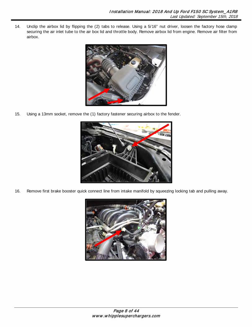
14. Unclip the airbox lid by flipping the (2) tabs to release. Using a 5/16” nut driver, loosen the factory hose clamp securing the air inlet tube to the air box lid and throttle body. Remove airbox lid from engine. Remove air filter from airbox.
15. Using a 13mm socket, remove the (1) factory fastener securing airbox to the fender.
16. Remove first brake booster quick connect line from intake manifold by squeezing locking tab and pulling away.

Installation Manual: 2018 And Up Ford F150 SC System_A1R8 Last Updated: September 15th, 2018
Page 9 of 44 www.whipplesuperchargers.com
17. Disconnect the EVAP solenoid electrical connector by squeezing locking tab and pulling away. Disconnect the EVAP solenoid quick connect fitting hose from the EVAP solenoid and from the intake manifold by releasing locking tab and pulling away.
18. Remove the second brake booster quick connect line from intake manifold by squeezing locking tab and pulling away.
19. Remove the brake booster vacuum line from check valve and IMRC vacuum lines from brake booster line (separate
where the arrow points). The check valve closest to the brake booster connector will be utilized.
20. Carefully cut the electric tape securing the ETC wires to the throttle body. Disconnect the electronic throttle electrical
connector by pushing up on the safety lock and then squeezing the connector and pulling away.

Installation Manual: 2018 And Up Ford F150 SC System_A1R8 Last Updated: September 15th, 2018
Page 10 of 44 www.whipplesuperchargers.com
21. Cut the factory zip-tie holding the factory heater hose to the valve cover. Remove the heater hose from passenger side of block by pulling locking tab back and pulling away. Using an 8mm socket, remove the stock heater tube.
22. Install the supplied driver side heater tube to passenger side of block. Install the supplied oring to the tube and apply light amount of grease to oring surface. Install tube into block and secure with the factory bolt using an 8mm socket. Torque to 89 lbs-in.
23. Disconnect the driver side heater tube quick connect fitting by squeezing and lifting away. Remove the heater tube
overflow hose using a pinch clamp tool. Using an 8mm socket on the 1 factory bolt, remove the heater tube. Install the supplied oring to the shorter heater tube and install to factory location, secure with stock bolt, torque to 89 lbs-in. Reconnect both factory hoses.

Installation Manual: 2018 And Up Ford F150 SC System_A1R8 Last Updated: September 15th, 2018
Page 11 of 44 www.whipplesuperchargers.com
24. Carefully remove the factory fuel line by releasing the blue safety lock, then squeezing the connector and pulling back. The fuel system may still have pressure, use protective eyewear and multiple rags to catch any possible fuel leak. Remove the fuel PSI sensor electrical connector from the driver side fuel rail by releasing the white locking tab and squeezing connector, then pulling away
25. Using a 3/8” fuel line removal tool, remove the feed line from the factory port injection system to the direct injection mechanical pump. Slide removal tool between the lines, securing the DI side until it releases. NOTE: THIS FUEL LINE HAS A CHECK VALVE, DO NOT FLIP ORIENTATION. DO NOT REMOVE FROM DI PUMP TO ELIMINATE CONFUSION. 90-DEG END ALWAYS CONNECTS TO FUEL FEED SUPPLY!
26. Remove fuel rail foam covers, these will not be reused. 27. Disconnect all fuel injector connectors by using a flat head screw driver on one side of the clip. Pry to one side and
clip will slide off. 28. Loosen the 4 bolts holding the fuel rails down, these go through to the cylinder head (10mm socket). Fuel rail does
not need to be removed.
Installation Manual: 2018 And Up Ford F150 SC System_A1R8 Last Updated: September 15th, 2018
Page 12 of 44 www.whipplesuperchargers.com
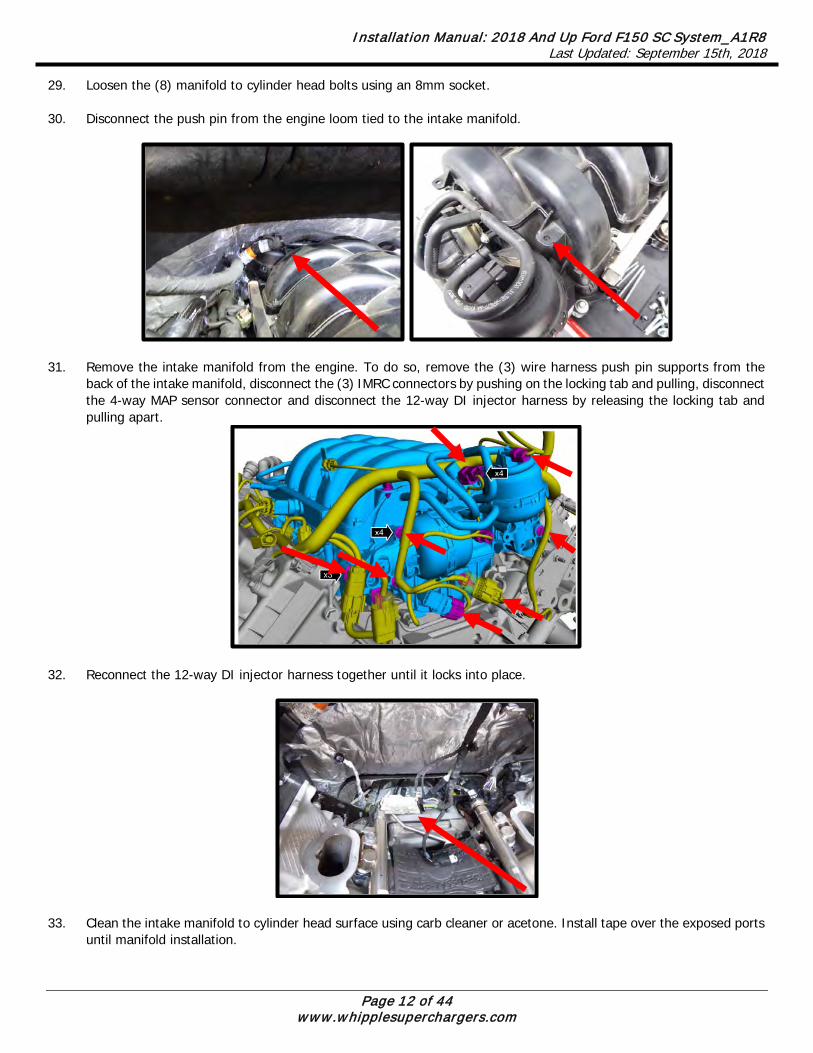
29. Loosen the (8) manifold to cylinder head bolts using an 8mm socket. 30. Disconnect the push pin from the engine loom tied to the intake manifold.
31. Remove the intake manifold from the engine. To do so, remove the (3) wire harness push pin supports from the
back of the intake manifold, disconnect the (3) IMRC connectors by pushing on the locking tab and pulling, disconnect the 4-way MAP sensor connector and disconnect the 12-way DI injector harness by releasing the locking tab and pulling apart.
32. Reconnect the 12-way DI injector harness together until it locks into place.
33. Clean the intake manifold to cylinder head surface using carb cleaner or acetone. Install tape over the exposed ports
until manifold installation.
Installation Manual: 2018 And Up Ford F150 SC System_A1R8 Last Updated: September 15th, 2018
Page 13 of 44 www.whipplesuperchargers.com
34. Loosen the (3) bolts securing the water pump pulley using a 10mm socket (while belt is on).
35. Remove the belt from the engine by using a 15mm socket on a ½” breaker bar and rotating the spring-loaded tensioner in a clockwise direction.
36. Remove the water pump pulley using a 10mm socket (this will be reused).
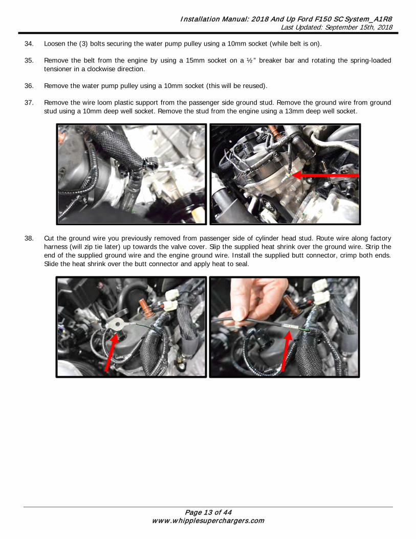
37. Remove the wire loom plastic support from the passenger side ground stud. Remove the ground wire from ground
stud using a 10mm deep well socket. Remove the stud from the engine using a 13mm deep well socket.
38. Cut the ground wire you previously removed from passenger side of cylinder head stud. Route wire along factory harness (will zip tie later) up towards the valve cover. Slip the supplied heat shrink over the ground wire. Strip the end of the supplied ground wire and the engine ground wire. Install the supplied butt connector, crimp both ends. Slide the heat shrink over the butt connector and apply heat to seal.
Installation Manual: 2018 And Up Ford F150 SC System_A1R8 Last Updated: September 15th, 2018
Page 14 of 44 www.whipplesuperchargers.com
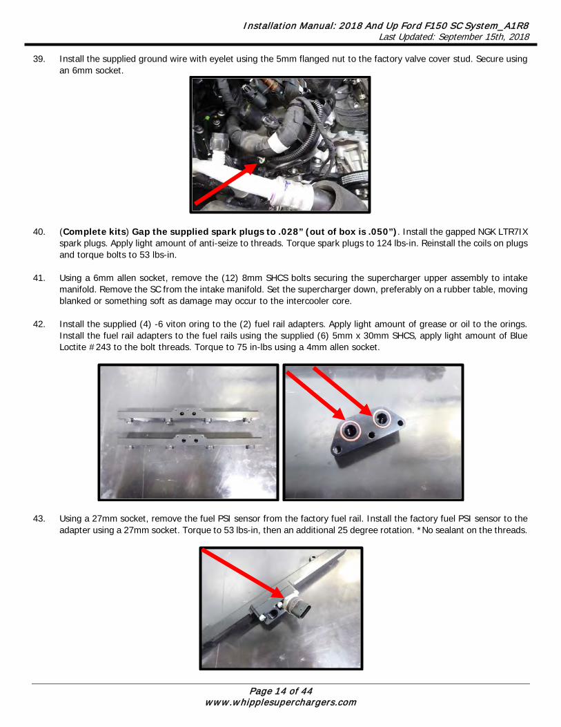
39. Install the supplied ground wire with eyelet using the 5mm flanged nut to the factory valve cover stud. Secure using an 6mm socket.
40. (Complete kits) Gap the supplied spark plugs to .028” (out of box is .050”). Install the gapped NGK LTR7IX
spark plugs. Apply light amount of anti-seize to threads. Torque spark plugs to 124 lbs-in. Reinstall the coils on plugs and torque bolts to 53 lbs-in.
41. Using a 6mm allen socket, remove the (12) 8mm SHCS bolts securing the supercharger upper assembly to intake
manifold. Remove the SC from the intake manifold. Set the supercharger down, preferably on a rubber table, moving blanked or something soft as damage may occur to the intercooler core.
42. Install the supplied (4) -6 viton oring to the (2) fuel rail adapters. Apply light amount of grease or oil to the orings.
Install the fuel rail adapters to the fuel rails using the supplied (6) 5mm x 30mm SHCS, apply light amount of Blue Loctite #243 to the bolt threads. Torque to 75 in-lbs using a 4mm allen socket.
43. Using a 27mm socket, remove the fuel PSI sensor from the factory fuel rail. Install the factory fuel PSI sensor to the
adapter using a 27mm socket. Torque to 53 lbs-in, then an additional 25 degree rotation. *No sealant on the threads.

Installation Manual: 2018 And Up Ford F150 SC System_A1R8 Last Updated: September 15th, 2018
Page 15 of 44 www.whipplesuperchargers.com
44. Install the supplied (1) -6 oring to the (1 of 2) 45mm long 9.49mm inlet fitting. Apply light amount of grease to oring for ease of installation. Install fitting to the fuel inlet block.
45. Install the supplied (1) -6 oring to the (1 of 2) 45mm long 9.49mm outlet fitting. Apply light amount of grease to
oring for ease of installation. Install fitting to the fuel inlet block. Install the supplied -6 ORB plug to the extra port.
46. Install the supplied -6 orings to the (4) inlet/outlet fittings. Install these (4) fittings into each side of the fuel rails.
Apply light amount of grease to oring for ease of installation. Using a ¾” wrench (or ¾” deep socket) on both the front and rear fittings, tighten both.

Installation Manual: 2018 And Up Ford F150 SC System_A1R8 Last Updated: September 15th, 2018
Page 16 of 44 www.whipplesuperchargers.com
47. Install the fuel injectors to the fuel rail, apply generous amount of grease to oring for easy installation. Install the supplied fuel injector position lock bracket to clock the supplied fuel injectors into proper position (competition kits with other injectors do not apply). Left Hand Driver side bank faces the front of the vehicle, Right Hand Passenger side faces towards the rear of the vehicle. While installing the lock bracket, secure the fuel injector so it does not add pressure to the injector body. Note: This is for dual spray pattern injectors only that must be at the correct angle. Competition kits should consult their tuner to verify whether the injector has to be clocked at a certain position (single spray pattern injectors do not). Failure to clock the injector correctly can cause severe running issues.
48. Mount fuel rails to intake manifold using the (4) 32mm long spacers between the manifold and fuel rail boss and the
(4) 6mm x 50mm SHCS, apply light amount of blue Loctite #243 to threads. Torque to 90 in-lbs using a 5mm allen socket.
49. Install the rear pre-made cross-over fuel line. Press until the click and lock into position.

Installation Manual: 2018 And Up Ford F150 SC System_A1R8 Last Updated: September 15th, 2018
Page 17 of 44 www.whipplesuperchargers.com
50. Install the supplied 2-bar MAP sensor to the back of the intake manifold using the supplied (1) 6mm x 16mm SHCS with the (1) 6mm AN washer with light amount of blue Loctite #243 to the threads. Apply generous amount of grease to the rubber oring for easy installation. Torque to 65 in-lb.
51. Pre-install the supplied MAP pigtail to the new MAP sensor.
Brown
Green4
3
2
1 Yellow
Purple
4
3
2
1MAP
VREF
IAT
Signal RTN Signal RTN
MAP
VREF
IAT
Male plugs intoFACTORY HARNESS SIDE
MAP Connector to plug into sensor shown
52. Install the supplied (8) manifold orings into the Whipple intake manifold.

Installation Manual: 2018 And Up Ford F150 SC System_A1R8 Last Updated: September 15th, 2018
Page 18 of 44 www.whipplesuperchargers.com
53. Remove the tape you previously installed on the exposed ports on cylinder head. Clean surface with carb cleaner or acetone.
54. Carefully install the intake manifold to the engine by laying directly to motor. If you miss or bump the manifold while
installing, verify the orings have not moved.
55. Install the (4) 6mm x 75mm SHCS bolts through the inner bolt bosses and through the intake manifold, install hand tight. Install the (6) 6mm x 40mm SHCS bolts through the intake manifold outer bolt bosses to cylinder head bolt holes and install hand tight.
6mm x 75mm 6mm x 40mm
56. Torque the (10) 6mm SHCS manifold bolts in the following pattern using a 5mm ball head allen socket. First pass:
88 lbs-in. Second pass: 106 lb-in.
5
1
10
4
87
9
6
3
2
Installation Manual: 2018 And Up Ford F150 SC System_A1R8 Last Updated: September 15th, 2018
Page 19 of 44 www.whipplesuperchargers.com
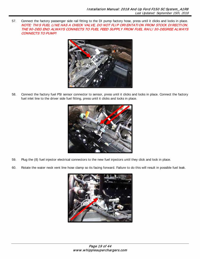
57. Connect the factory passenger side rail fitting to the DI pump factory hose, press until it clicks and locks in place. NOTE: THIS FUEL LINE HAS A CHECK VALVE, DO NOT FLIP ORIENTATION FROM STOCK DIRECTION. THE 90-DEG END ALWAYS CONNECTS TO FUEL FEED SUPPLY FROM FUEL RAIL! 30-DEGREE ALWAYS CONNECTS TO PUMP!
58. Connect the factory fuel PSI sensor connector to sensor, press until it clicks and locks in place. Connect the factory
fuel inlet line to the driver side fuel fitting, press until it clicks and locks in place.
59. Plug the (8) fuel injector electrical connectors to the new fuel injectors until they click and lock in place.
60. Rotate the water neck vent line hose clamp so its facing forward. Failure to do this will result in possible fuel leak.

Installation Manual: 2018 And Up Ford F150 SC System_A1R8 Last Updated: September 15th, 2018
Page 20 of 44 www.whipplesuperchargers.com
61. Install the supplied front fuel cross over line to the front until they click and lock in place. The 90deg end goes on driver side fitting. Route behind water neck vent line. Ensure that its free from rubbing anything during engine vibration.
62. Measure the factory passenger side heater hose, 5” from the straight and mark the hose. Cut the hose at the mark.
Install the supplied ¾” hose coupler and shrink band clamp into stock hose. Use heat gun to shrink the shrink band until coupler is locked in place. Install the supplied 1” x 19.5” sleeving over hose, then the heat shrink and shrink band clamp. Install the ½” (#18F150-HS001) hose to the hose coupler. Slide sleeving to end of hose, use shrink band clamp to secure hose and sleeving to coupler using heat gun. Slide heat shrink over end of hose and sleeving, shrink both using heat gun. Secure hose using worm clamp to heater tube.

Installation Manual: 2018 And Up Ford F150 SC System_A1R8 Last Updated: September 15th, 2018
Page 21 of 44 www.whipplesuperchargers.com
63. Cover the (1) IMRC solenoid and (2) IMRC position sensor connectors with electric tape and secure to the factory loom at the back of the engine.
64. Install the (1) supplied manifold top oring (.103” x 51.25”) into the oring groove. Use silicone/grease in receiver groove
to help oring stay in place.
65. The supercharger must be filled with oil prior to use. This supercharger is shipped without oil inside. The oil is in a separate bottle supplied with your kit and is pre-measured for the exact amount of oil.
*CAUTION* SEVERE DAMAGE TO THE COMPRESSOR WILL OCCUR IF YOU UNDER/OVERFILL THE SC GEAR CASE
Make sure the SC is sitting on a flat surface.
Remove -6AN allen plug (1/4” allen wrench) and fill SC with WHIPPLE SC OIL ONLY!! Fill to the middle of the sight glass. Tip from side to side then with flat check oil again, add as necessary.
NOTE: The W175FF compressor takes a maximum of 8 fl/oz and minimum of 7 fl/oz.
Reinstall -6AN allen plug.
NOTE: After running the SC, the oil level will lower due to oil filling the bearings. The proper level while not running should be between the bottom of the sight glass and the middle and will vary when running and not running.
Change SC oil every 100,000 miles and only use WHIPPLE SC OIL ONLY!!
OIL FILL PLUG
MAXIMUM OIL LEVEL
MINIMUM OIL LEVELOIL LEVEL OPERATING RANGE

Installation Manual: 2018 And Up Ford F150 SC System_A1R8 Last Updated: September 15th, 2018
Page 22 of 44 www.whipplesuperchargers.com
66. Install the supplied #117 Nitrile orings (2) to the aluminum intercooler fitting. Apply light amount of grease to each surface. Install fitting into upper intercooler passage by carefully sliding in, be cautious of the oring and ensure there is no debris during installation.
67. Install the supplied #126 Viton oring to the manifold top intercooler passage location. Apply light amount of grease
to oring to help secure in place. Install the supplied intercooler hose connect fitting to upper intercooler passage. Apply light amount of Blue Loctite #243 to threads of the supplied (2 of 4) 6mm x 10mm FHSCS.
68. Carefully install the supercharger assembly to the intake manifold. Install the EVAP bracket to the 3 and 4 bolts
(driver side from front) bolt bosses. Use the supplied (10) 8mm x 30mm SHCS and (2) 8mm x 60mm SHCS to secure SC assembly (6mm allen socket). Torque the supercharger bolts in an inside-out, crisscross pattern. Torque all bolts to 13 lbs-ft. on first pass, 17 lbs-ft on second pass.
EVAP BRACKET
8MM X 30MM

Installation Manual: 2018 And Up Ford F150 SC System_A1R8 Last Updated: September 15th, 2018
Page 23 of 44 www.whipplesuperchargers.com
69. Remove the factory EVAP hose from the EVAP solenoid. Install EVAP solenoid to pre-installed bracket. Connect factory hose to EVAP solenoid.
70. Install the supplied -6 orings (4) to the inlet fittings. Apply light amount of grease to the orings for ease of installation. Install the 15.82 to 6 ORB to the passenger side inlet open thread. Install the (2) 9.89 to 6 ORB fittings to the driver side inlet open threads. Install the 6 ORB plug in the middle thread.

Installation Manual: 2018 And Up Ford F150 SC System_A1R8 Last Updated: September 15th, 2018
Page 24 of 44 www.whipplesuperchargers.com
71. Install the supplied #117 Nitrile orings (2) to the aluminum intercooler fitting. Apply light amount of grease to each surface. Install fitting into lower intercooler passage by carefully sliding in, be cautious of the oring and ensure there is no debris during installation.
72. Install the supplied #126 oring to the manifold bottom intercooler passage location. Apply light amount of grease to
oring to help secure in place. Install the supplied intercooler hose connect fitting to lower intercooler passage. Apply light amount of blue Loctite #243 to threads of the supplied (2 of 4) 6mm x 10mm FHSCS.
73. Install the supplied ¼” ID bypass actuator hose (#18F150-HS005) to the bypass nipple and ¼” nipple above first
cylinder on driver side.

Installation Manual: 2018 And Up Ford F150 SC System_A1R8 Last Updated: September 15th, 2018
Page 25 of 44 www.whipplesuperchargers.com
74. Using a razor blade, carefully cut the 90deg and 45 deg quick connect fittings from the factory PCV line. Install these fittings into the supplied 1/2” x 7” hose (#18F150-HS004). Install the ¾” x 8” sleeving and heat shrink to the ½” x 7” hose. Shrink sleeving and heat shrink, using the heat shrink material to cover the cut ends of the hose.
75. Install the new PCV hose to the PCV fitting (passenger side valve cover) to the SC inlet (passenger side).
76. Install the supplied 3/8” x 8 ½” EVAP hose (#18F150-HS002) to the EVAP solenoid and bottom inlet fitting.
77. Install the supplied electronic throttle pigtail to the factory electrical connector. Push until it locks in place, then lock the safety lock. Leave near the thermostat housing for later connection to throttle body.

Installation Manual: 2018 And Up Ford F150 SC System_A1R8 Last Updated: September 15th, 2018
Page 26 of 44 www.whipplesuperchargers.com
78. Using a 10mm socket, remove the (2) factory fasteners from the timing chain to head cover and (1) from water pump (for new idler plate).
79. NOTE: Pay close attention to identifying numbers on stands/plate. Install the (3) support stands to the front idler plate. These are loose fit, therefore you must tilt backwards during installation or the stands will fall. You can use masking tape to help hold in place during installation if installation becomes difficult. Each support stand is marked with an identifying number, as well as the idler plate for ease of placement. Assemble together with the number facing out for future reference.
80. Using a 10mm socket, remove the (3) water pump pulley bolts you previously loosened (these will be reused). 81. Use the supplied (3) 8mm x 90mm SHCS to secure the idler plate to the front of the passenger side of engine, install
hand tight. NOTE: This plate must be left loose to install SC assembly properly.

Installation Manual: 2018 And Up Ford F150 SC System_A1R8 Last Updated: September 15th, 2018
Page 27 of 44 www.whipplesuperchargers.com
82. Install the supplied (1) 10mm x 25mm SHCS through the idler plate and supercharger front support. Install hand tight. Torque the 10mm bolt to 25 lbs-ft. and the (3) 8mm idler plate bolts to 18 lbs-ft.
83. Install the supplied (1) smooth idler pulley #36101 using the (1) step spacer along with the “Tee-nut” in the idler plate. The tee-nut needs to be installed from the back of the plate, this allows for belt slack adjustment. Sandwich the idler pulley to the step spacer using the supplied (1) step spacer and (1) ½”-13 x 1 ¾” SHCS. Leave hand tight until the belt installation.
84. Install the supplied (1) smooth idler pulley #36101 and (1) grooved idler pulley #36326 to the idler plate using the (2) step spacers. Sandwich the idler pulley to the step spacer using the supplied (2) step washer and (2) ½”-13 x 1 ¾” SHCS and torque to 30 lbs-ft. using a 3/8” allen socket. Use light amount of anit-seize on threads.

Installation Manual: 2018 And Up Ford F150 SC System_A1R8 Last Updated: September 15th, 2018
Page 28 of 44 www.whipplesuperchargers.com
85. Reinstall the water pump pulley using the (3) factory fastener. Wrap the belt around the pulley to hold in place and torque to 18 lbs-ft.
86. Install the supercharger pulley using the supplied (4) 6mm x 12mm SHCS using a 5mm allen socket. Leave hand
tight until belt installation. 87. Install the supplied supercharger belt by following the routing diagram. Using an 15mm socket on a ½” breaker bar,
open the factory tensioner to its max open position. Push the adjustable/sliding smooth idler pulley down as far as it can. Once in position, lock the adjustable idler pulley by torqueing the center SHCS to 18 lbs-ft. *NOTE: You must always put the tensioner at or near its max open position. Failure to set properly will result in belt issues during hard accel or decal. Changing supercharger pulley diameters may require different belt lengths.
88. Torque the supercharger (4) 6mm x 12mm SHCS bolts to 130 lbs-in using a 5mm allen socket. 89. Install the intercooler pump to the water reservoir using the supplied clamp and rubber strip (leave slightly loose to
position after hose installation). Install the supplied 90deg rubber hose and pinch clamps to reservoir and intercooler pump. Once pump is in position, tighten clamp holding IC pump to reservoir. Note: Make sure pump outlet is facing directly up.

Installation Manual: 2018 And Up Ford F150 SC System_A1R8 Last Updated: September 15th, 2018
Page 29 of 44 www.whipplesuperchargers.com
90. Using a body panel pin tool or flat head screw driver, remove the factory radiator closeouts from both sides of the radiator. This will not be reused.
91. Remove the stock horn bracket with horns from the vehicle using a 13mm socket.
92. Remove the horns from the factory bracket and relocate them to the new supplied bracket as shown.

Installation Manual: 2018 And Up Ford F150 SC System_A1R8 Last Updated: September 15th, 2018
Page 30 of 44 www.whipplesuperchargers.com
93. Install the LTR brackets to the vehicle in the factory bolt holes. Use bracket #3102656 on passenger side, secure with supplied (2) 6mm x 20mm hex head flanged bolts, torque to 89 lbs-in using a 10mm socket. Use bracket #3102655 on passenger side, secure the tab to factory location, secure with supplied (1) 6mm x 16mm hex head flanged bolts, torque to 89 in-lbs using a 10mm socket. Mount the LTR to the brackets with the 5/8” barb on passenger side, using the supplied (4) 8mm x 16mm FHSCS and (4) .813” sleeved washer. Torque to 13 lbs-ft. Verify the LTR cannot touch the factory radiator, it must have a minimum of .25” clearance.
94. Reinstall new horn bracket and horns to factory location, using factory nut. Torque to 106 lbs-in. Zip-tie wire to factory harness for clean installation.

Installation Manual: 2018 And Up Ford F150 SC System_A1R8 Last Updated: September 15th, 2018
Page 31 of 44 www.whipplesuperchargers.com
95. Install the supplied (4) rubber grommets and steel bushing into the (4) holes located on the driver and passenger side frame.
96. Install the supplied steel nut plates (2), (1) per side up through square opening with nuts facing up.
97. Install the IC reservoir to the (2) nut plates using the (4) 8mm x 25mm flanged hex headed bolt. Start (1) on each side to align holes to bushing. If off, you can use screwdriver to align the nut plate and bushing before installing the final (2) bolts. Torque to 15 lb-ft using a 13mm socket.
Installation Manual: 2018 And Up Ford F150 SC System_A1R8 Last Updated: September 15th, 2018
Page 32 of 44 www.whipplesuperchargers.com
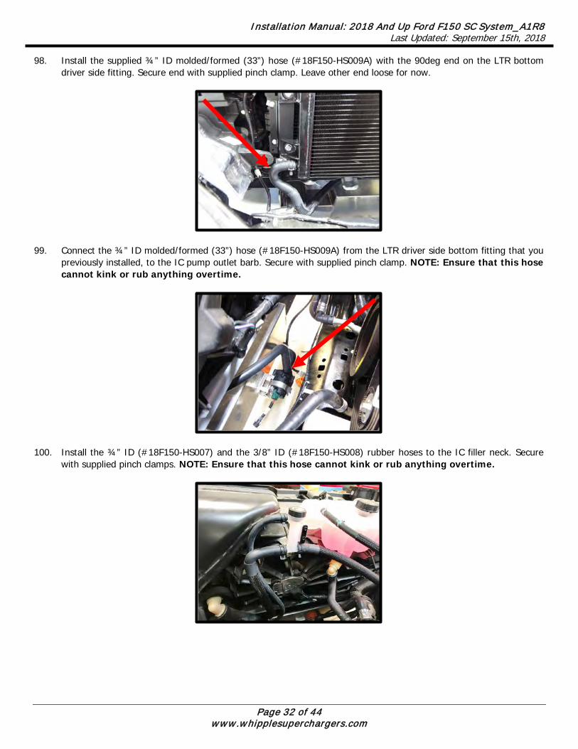
98. Install the supplied ¾” ID molded/formed (33”) hose (#18F150-HS009A) with the 90deg end on the LTR bottom driver side fitting. Secure end with supplied pinch clamp. Leave other end loose for now.
99. Connect the ¾” ID molded/formed (33”) hose (#18F150-HS009A) from the LTR driver side bottom fitting that you
previously installed, to the IC pump outlet barb. Secure with supplied pinch clamp. NOTE: Ensure that this hose cannot kink or rub anything overtime.
100. Install the ¾” ID (#18F150-HS007) and the 3/8” ID (#18F150-HS008) rubber hoses to the IC filler neck. Secure
with supplied pinch clamps. NOTE: Ensure that this hose cannot kink or rub anything overtime.

Installation Manual: 2018 And Up Ford F150 SC System_A1R8 Last Updated: September 15th, 2018
Page 33 of 44 www.whipplesuperchargers.com
101. Connect the ¾” ID hose (#18F150-HS007) and the 3/8” ID hose (#18F150-HS008) hose coming from the IC filler neck to the ¾” and 3/8” barb fitting on the IC reservoir. Secure with supplied pinch clamp. NOTE: Ensure that this hose cannot kink or rub anything overtime.
102. Route the supplied 90deg intercooler feed hose (#18F150-HS010A) (39”) to the bottom intercooler fitting (behind
the idler plate). Install the 90deg hose to the bottom barb fitting and secure with the supplied pinch clamp. Route the other end over the valve cover, below the AC line and through the gap between the radiator and front clip. Route to the heat exchanger out fitting (passenger side upper fitting). Secure end with supplied pinch clamp. *NOTE: Make sure the hose does not and cannot kink during routing. DO NOT lay the hose on the cam sensor wires, this will lead to failure over time. Use the supplied dual zip ties to secure in place and split the cam sensor wires.

Installation Manual: 2018 And Up Ford F150 SC System_A1R8 Last Updated: September 15th, 2018
Page 34 of 44 www.whipplesuperchargers.com
103. Using a 10mm socket, remove the stock coolant reservoir driver side bolt. Install the IC filler tee bracket under the coolant reservoir mounting tab. Reinstall factory bolt. Secure filler tee to the bracket using the (2) 6mm x 12mm flanged BHCS (4mm allen socket). Secure the bracket to the valve cover using the supplied 8mm x 12mm SHCS.
104. Install the ¾” ID rubber hose (#18F150-HS006) from the top IC fitting (outlet) to the IC filler neck. Secure both
ends with supplied pinch clamps.
105. Install the supplied 15/32” (#F150-2000) brake booster hose to the factory check valve. Route this line up to the
front of the driver side valve cover (secure with 2 zip-ties to factory wire harness). Connect 90deg quick connect to bottom fitting in the supercharger inlet. Push until it clicks into place.

Installation Manual: 2018 And Up Ford F150 SC System_A1R8 Last Updated: September 15th, 2018
Page 35 of 44 www.whipplesuperchargers.com
106. Install the supplied throttle body oring to the supercharger inlet. Apply light amount of grease to help hold in place.
107. (Stock throttle body) Install throttle body adapter to supercharger inlet using the supplied (4) 6mm x 14mm FHCS (4mm allen socket). Torque to 88 lbs-in. Install stock TB oring to adapter. Install stock TB to throttle adapter using the supplied (4) 6mm x 50mm FHSCS. Torque to 88 lbs-in.
108. (Whipple 132mm Crusher throttle body) Install throttle body to supercharger inlet using the supplied (3) 6mm
x 25mm SHCS and (1) 6mm x 50mm SHCS using a 5mm allen socket. Torque to 88 lbs-in.
109. Connect the electronic throttle extension to the electric motor. Press until it clicks and locks into place. Press the
safety lock until it clicks and locks into place. Secure harness to the intercooler line with a zip-tie to ensure proper clearance from the belt system.
Installation Manual: 2018 And Up Ford F150 SC System_A1R8 Last Updated: September 15th, 2018
Page 36 of 44 www.whipplesuperchargers.com
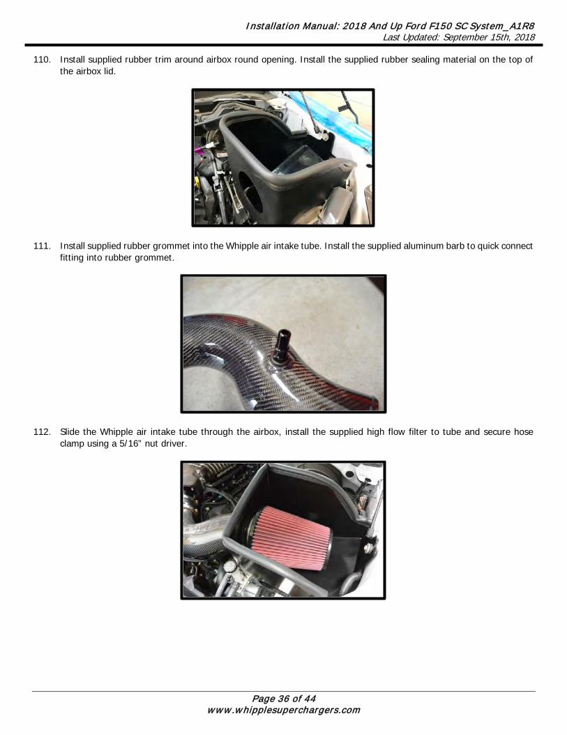
110. Install supplied rubber trim around airbox round opening. Install the supplied rubber sealing material on the top of the airbox lid.
111. Install supplied rubber grommet into the Whipple air intake tube. Install the supplied aluminum barb to quick connect
fitting into rubber grommet.
112. Slide the Whipple air intake tube through the airbox, install the supplied high flow filter to tube and secure hose clamp using a 5/16” nut driver.

Installation Manual: 2018 And Up Ford F150 SC System_A1R8 Last Updated: September 15th, 2018
Page 37 of 44 www.whipplesuperchargers.com
113. (Whipple 132mm Crusher throttle body) Install the supplied 5” ID x 2” silicone hose over air inlet tube so it’s not hanging over the end. Install the air inlet tube between the filter and throttle body. Slide silicone hose over throttle body. Secure all ends with the supplied #80 hose clamps.
114. (Stock throttle body installations) Install the supplied reducer silicone hose over air inlet tube. Connect the other end to the stock throttle body. Secure all ends with the supplied hose clamps.
115. Secure the supplied (COYO-2000) driver side valve cover vent line quick connect fitting to the 5/8” fitting in the inlet
tube previously installed.

Installation Manual: 2018 And Up Ford F150 SC System_A1R8 Last Updated: September 15th, 2018
Page 38 of 44 www.whipplesuperchargers.com
116. Locate the stock hole in the battery box. Use the supplied plastic push pin to secure the intercooler relay and fuse holder to the battery box. Route the power wire to the main power stud at the battery side. Route the ground wire around the front of the battery box, then back towards the fuse box. Zip-tie each wire for a clean installation.
117. Using a 10mm socket, remove the nut on the power stud, located on the positive battery connector. Install the IC
pump relay power eyelet (red wire) to the power stud on the battery positive (+) stud. Use a 10mm socket to secure stock and IC power wire.
118. Remove the ground bolt from the passenger side inner fender using an 8mm socket. Install IC pump relay ground eyelet here. Secure with factory bolt using an 8mm socket.

Installation Manual: 2018 And Up Ford F150 SC System_A1R8 Last Updated: September 15th, 2018
Page 39 of 44 www.whipplesuperchargers.com
119. Pull the red 10amp fuse from position #F17 (ABS). Install the 10amp red fuse in the unused fuse slot on the fuse tap. Install the supplied fuse tap into position #F17 (ABS). Note: 10amp red fuse should be in bottom slot, 5amp should be in top slot. Make sure wire has enough room when fuse cover closes, route around fuses for clean installation.
120. Secure the relay/fuse along with the harness for a clean installation. 121. Refill the Engine coolant. Verify that your coolant drain is closed, and use a filter/strainer to pour the recycled
coolant/water mixture that you drained from the radiator. If necessary top off with a Ford approved engine coolant. Whipple also recommends running 2 bottles of Redline Water Wetter which can be found at most automotive parts stores. WARNING!! DO NOT USE TAP WATER OR ANY NON-FORD APPROVED ENGINE COOLANT, THIS WILL CAUSE CORRISION IN THE SYSTEM. **(Vehicles that come equipped with Ford Motorcraft Orange must use Motorcraft Specialty Orange. Start engine to completely fill system.
122. Install the jackshaft cover using the supplied (4) rubber grommets in the cover, (4) stainless bushings and (4) 5mm
x 12mm BHCS. Use a 3mm allen to secure to supercharger system. 123. Attach the negative cable to the battery and tighten using a 8mm wrench.
124. Install the radiator shroud cover using the factory push pins (8).
125. (Complete kits) Install the supplied 50-state legal sticker (when applicable) to the hood as the factory emissions
sticker. Use light amount of acetone to clean surface before installing.

Installation Manual: 2018 And Up Ford F150 SC System_A1R8 Last Updated: September 15th, 2018
Page 40 of 44 www.whipplesuperchargers.com
126. Attach the “91 OCTANE OR HIGHER” decal to the gas tank fill cap or door.
127. Using a Lisle 24680 Spill-Free Funnel, or equivalent, secure the appropriate filler neck adapter to the filler neck/surge
tank. 128. Attach the funnel and fill with a 50/50 mixture of coolant and distilled water until the funnel is half full. Whipple
recommends Ford Motorcraft Orange to match the stock color. Whipple also recommends 1 bottle of Red Line Water Wetter or equivalent. Note: The Whipple IC system is compatible with all common types of antifreeze. Never use tap water, this will cause corrosion and destroy the system.
129. Turn the ignition to the ON position and listen for the pumps electric motor to cycle. Air bubbles will begin to purge
from the system as the coolant level drops. Add coolant to the funnel as necessary. Note: Do NOT let the coolant level in the funnel run empty as this may introduce air into the system.
130. To build more pressure in the intercooler system, try squeezing the intercooler hoses while the pump is cycling.
Building pressure in the system will help purge the trapped air from the intercooler system. It can also help to lift the filler neck 4”-8” higher than its mount to help purge the air.
131. Cycle the ignition OFF and wait a few seconds for the pump to stop.
132. Cycle the ignition to the ON position again and repeat until the sound of the electric pump is continuous without any
pulsation. NOTE: During water pump start-up, it is normal for a slight pulsation to occur. Once the pump has reached its maximum cycle speed, no pulsations should be present.
133. Periodically inspect the water pump flow after a few drive cycles and re-fill the intercooler system as necessary.
134. Several drive cycles may be required to completely purge the air from the intercooler system. During a drive cycle,
the intercooler system will build up pressure as the supercharger temperature increases. Any residual air trapped in the system will gradually bleed out of the surge tank when the cap is removed. Use a rag when removing in case there is excess pressure. Never operate at WOT until all air has been evacuated.
The electric water pump used on the Whipple SC system has a built-in micro-processor that will vary pump cycle speed when air bubbles are present in the system. If a significant amount of air is trapped in the system, the pump may cycle at a lower speed and pulsations are likely to occur resulting in poor cooling performance.
For the best result, it is highly recommended to use a Radiator Cooling System Vacuum Purge and Refill Kit to properly evacuate the air from the intercooler system before filling the 50/50 mixture of coolant and distilled water. If one is not available, the following procedure will be adequate.
WARNING: Always avoid removing the fil ler neck cap when the system is hot. The hot coolant is under pressure and may spray out causing burns.

Installation Manual: 2018 And Up Ford F150 SC System_A1R8 Last Updated: September 15th, 2018
Page 41 of 44 www.whipplesuperchargers.com
135. If your system included a flash tool, follow the included instructions to reflash the PCM.
136. Install the radiator shroud cover using the factory push pins (9).
137. Reinstall the grill shell in the reverse order.
138. Turn the Ignition key on, do not start the engine (this will turn ON the fuel pump for 2 seconds). Inspect for leaks such as fuel, coolant, and intercooler coolant, correct as required.
139. Start the engine and let idle. The engine should idle normally between 600-700 rpm at normal operating temps.
Inspect for leaks. After running for 2 minutes turn off engine and inspect the level in the engine radiator and the Intercooler tank. With the key in the ON position engine off, inspect the coolant in the intercooler tank, the coolant should flow in the tank. If it does not, the coolant circuit has an air pocket trapped in it. To remove the air pocket, with key off, remove the IC filler neck cap and fill with coolant to mid-level. Reinstall cap, turn key on, for 15 seconds. Turn key off, remove fill cap and repeat until all air is bled.
140. Before driving, make sure that you have 91 or higher octane fuel in the system. Not ½ tank of 87 and ½ tank of 91,
all 91 or better fuel in the system. Whipple does not recommend octane booster for low octane fuel. The system adapts to higher octane fuel when it’s available.
141. Test drive vehicle for the first few miles under normal driving conditions. Listen for any noises, vibrations, engine
misfire or anything that does not seem normal. The supercharger does have a slight whining noise under boost conditions, which is normal. If you chose the 132mm billet throttle body, idle may take a few minutes to learn.
142. Re-check the radiator and intercooler reservoir coolant level regularly over the first 1,000 miles, top off level as
needed. Do not operate at WOT until IC system is bled properly. 143. Re-check SC oil level regularly over the first 1,000 miles, level may drop very slightly as it fills the bearings and
cavities. 144. Inspect belt system, readjust if necessary. It’s common for the belt to stretch after first use. 145. After the initial test drive, go through the belt tensioner process again. When next you start driving, gradually work
the vehicle to wide open throttle runs. Listen for any engine detonation (pinging). If engine detonation is present, let up on the throttle immediately. Most detonation causes are low octane gasoline still in the tank. The F150 uses factory wide band O2 sensors, which means it will control air fuel ratio to the target. Fuel trims will adapt for variances. Fuel pressure is 70psi +/- 5psi and never should dip below the specified margin. Trucks with high mileage may have clogged fuel filters or deteriorated fuel pumps. Any truck with 50,000 or more miles should verify fuel pressure during testing.
146. If you have questions about your vehicles performance, please check with your installation facility or call Whipple
Superchargers at 559.442.1261, Monday through Friday from 8am to 5:00pm, pacific time or email questions to [email protected].

Installation Manual: 2018 And Up Ford F150 SC System_A1R8 Last Updated: September 15th, 2018
Page 42 of 44 www.whipplesuperchargers.com
WARNING!! Verify the bypass actuator is working properly. To monitor, look at the bypass arm when the motor is not running. Start engine and verify that the actuator arm has opened. This arm will be extended when the engine is above 1” of vacuum (boost) and will be open when there is more than 1” of engine vacuum. There is a great deal of misinformation about the function of supercharger bypass systems. The supercharger is a positive-displacement pump; that is, so long as it is rotating, it is always pumping air. During low demand or high vacuum operation (i.e. idle, deceleration, and light throttle cruise), the pumping action is undesirable as it creates unwanted heat and noise. The bypass circuit, when open, prevents any pressure buildup across the supercharger and allows air to circulate through the rotors, allowing the supercharger to “idle” freely during these conditions. This results in reduced noise, and by reducing heat buildup in the intake, significantly improves street and strip performance. As throttle demand increases, the bypass circuit is closed, resulting in full performance and strip performance. As throttle demand increases, the bypass circuit is closed, resulting in full performance from the supercharger. The bypass circuit is never used to limit or control boost during full-throttle operation and defeating or altering the bypass function will not result in improved performance in any condition, and will result in poor drivability and possible supercharger damage.
INSTALLATION NOTES
MAINTENANCE AND SERVICE Be sure to follow the maintenance and service recommendations below to optimize the life and performance of your Whipple-supercharged vehicle. For best performance and continued reliability it is essential to adhere to the following guidelines:
1. Use only premium grade fuel (91-octane or higher). RON+MON/2. The PCM calibration will automatically
detect higher octane levels and will increase power accordingly. 2. Always listen for any sign of spark knock or pinging. If present, discontinue use immediately and consult your
vehicle owner’s manual. 3. Do not operate the vehicle at large throttle opening if the MIL lamp is on steadily. This indicates an electronic
engine control malfunction: reduce throttle opening to a safe location. Use the supplied flash tool to read the DTC and consult with Whipple or your Whipple dealer.
4. Check the supercharger oil level at every engine oil change. Add Whipple SC oil to the supercharger if required. Do not overfill the supercharger rear gear case.
5. Change the oil in the supercharger every 100,000 miles unless pulley is changed. Changing pulleys requires shorter mileage intervals. Use Whipple SC oil or Ford #XL-4 only.
!! CAUTION !! Severe damage to the compressor will occur if you overfill the supercharger rear gear case.
6. Do not operate the vehicle at large throttle opening if the MIL lamp is on steadily. This indicates an electronic engine control malfunction: reduce throttle opening and consult your vehicle dealer.
7. Inspect and clean your high-flow air filter element every 7,500 miles. 8. Inspect and replace spark plugs every 20,000 miles. Only run specified NGK plugs. 9. Follow your factory service intervals for oil changes and other typical maintenance items. 10. Check the supercharger/accessory drive belt. Adjust or replace as required
!! CAUTION !! Any modification to your vehicle’s new computer program may cause serious damage to the engine and/or drive train. The PCM is locked to the VIN, never let anyone, including dealerships install updates to the PCM. Modifications to the PCM will lock power to stock power levels.

Installation Manual: 2018 And Up Ford F150 SC System_A1R8 Last Updated: September 15th, 2018
Page 43 of 44 www.whipplesuperchargers.com
CONGRATULATIONS Your new Whipple Supercharger is engineered to significantly increase your engines power across a broad range of RPM’s. It is Whipple’s goal to improve your driving experience for many miles and years to come. Whipple Superchargers operate as an air pump and contain internal rotors that are driven by the engine’s crankshaft and serpentine belts. The supercharger compresses outside air and channels it into the engine’s intake ports. Because of their design, superchargers may generate some additional noise over the standard, normally aspirated induction system. At idle, you may hear a medium-pitch rattle from the supercharger main housing. This will diminish at about 400-500 rpm above idle. You may also experience a muffled high-pitched whine during acceleration. This is caused by the pumping action of the supercharger compressing air and only occurs during boost conditions. It is inaudible during part-throttle acceleration. These are normal noises associated with any supercharger and have no effect on supercharger performance or engine durability. Your supercharger is warranted by Whipple Superchargers, please see your terms and conditions on the back of your invoice for more information in regards to the limited warranty. NOTE: Whipple Superchargers will not authorize any warranty repair work or supercharger replacement for normal noise.
IMPORTANT INFORMATION CHASSIS DYNO Due to the 125mph speed limit, one must always run in a gear that will not limit the engine rpm below 7000rpm. Therefore, 5th gear is typically the best. 7th gear is 1:1 and gives the highest power results, but is not available due to drive shaft, tire safety. Never run back to back runs without a proper cool down. You must let the engine cool down for 5 minutes between runs as you won’t have adequate airflow to keep the vehicle in proper temperature ranges. BOOST LEVELS All Whipple kits are shipped with boost levels that Whipple feels achieves maximum power while maintaining reliability with stock engines (@ sea level). Additional pulley’s are available for lower and higher boost levels, the supplied calibration (complete kits) for the original pulley or larger (lower boost). Higher boost levels must run higher octane levels such as 104, 110, 116, etc. or be custom tuned. One can always lower boost with no cal changes required. EXHAUST Cat-back exhaust systems help reduce heat and minimize exhaust back pressure. They do not affect the calibration and are always a good idea for added safety and performance. Long tube headers and/or high flow cats require custom calibrations and are not supported by Whipple. While they make more power, they greatly affect the tuning and therefore this should be custom tuned by a reputable tuner. FUEL SYSTEM The Whipple fuel system (FLOW) needs no additional changes for power levels supplied by Whipple. Any smaller pulley changes, custom calibration, custom engines may require fuel system changes. Whipple programmable fuel pump boosters should be used on anything past 650RWHP. At 750RWHP, the supplied fuel injectors are at max capacity and should be changed to higher flowing injectors. AIR FUEL RATIO Air fuel ratio is the measurement of the amount of air and fuel being burned during the combustion process. In order for you to monitor the air fuel ratio, you must have a 18mm bung welded into the exhaust or use OBD data logger to monitor the factory wide bands. The ideal placement is pre catalytic converter as the catalytic converter can give false readings. While in some cases, it may not be possible to measure air fuel pre-cat, one must verify that post-cat that the motor is running at stoich at idle and should technically show .20 to .50 leaner air fuel ratio.

Installation Manual: 2018 And Up Ford F150 SC System_A1R8 Last Updated: September 15th, 2018
Page 44 of 44 www.whipplesuperchargers.com
The Whipple supplied calibration has is tuned for WOT .82 Lambda considering 91 octane fuel with 10% Ethanol. Whipple maintains Catalytic saver mode which richens the target air fuel to maintain cat life when required. During this, the air fuel may lower up to .75 Lambda to maintain temps. FUEL OCTANE Never run a fuel octane that is below 91octane, (RON+MON)/2 and never run fuel with more volume than 10% Ethanol. It is recommended, when available, to run 92-94 octane. Never mix mid-level (below 91) with 91+, this is very dangerous and can cause severe engine damage. Do not attempt to increase octane ratings with generic octane boosters, these are very hard on spark plugs and many brands do very little to the actual octane rating (1 point is .1 octane). For emergency situations and racing applications, the best octane booster found to date is Boostane (#1 choice). Some other brands are hard on spark plugs so constant use will require increased spark plug maintenance. The PCM constantly adapts, if it senses better fuel, it will increase power accordingly. ENGINE COOLANT Whipple recommends running a 50/50 mix of distilled water and coolant. The engine temp should run between 195-215deg F under normal driving conditions. The fans are turned on at an earlier temp to promote cooler operating temps. We also recommend 1-2 bottles of Red Line Water Wetter coolant additive. This will reduce air bubble insulation, which increases overall engine temp. FUEL LEVEL Never operate at WOT when the vehicle fuel levels are below a 1/8 tank. Low fuel levels could cause the fuel pump to cavitate and you’ll have fuel flow spikes resulting in lean conditions and consequently detonation.