supercapacitors fm series
TRANSCRIPT
1© KEMET Electronics Corporation • KEMET Tower • One East Broward Boulevard S6012_FM • 7/17/2020Fort Lauderdale, FL 33301 USA • 954-766-2800 • www.kemet.com
One world. One KEMET
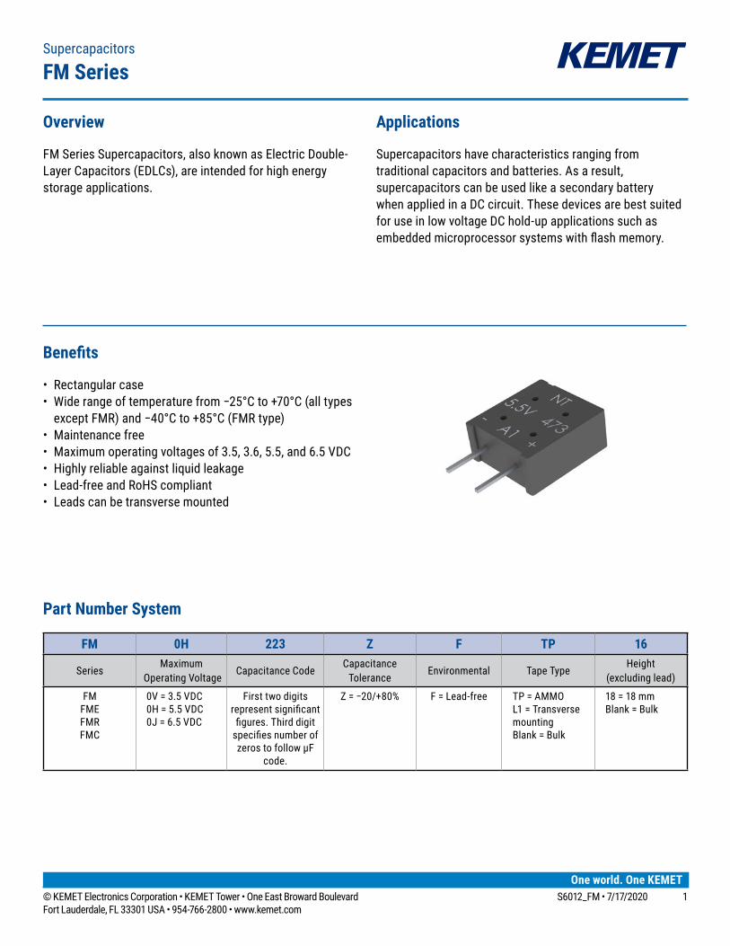
Benefits
• Rectangular case• Widerangeoftemperaturefrom−25°Cto+70°C(alltypesexceptFMR)and−40°Cto+85°C(FMRtype)
• Maintenance free• Maximum operating voltages of 3.5, 3.6, 5.5, and 6.5 VDC• Highlyreliableagainstliquidleakage• Lead-free and RoHS compliant• Leadscanbetransversemounted
Overview
FMSeriesSupercapacitors,alsoknownasElectricDouble-LayerCapacitors(EDLCs),areintendedforhighenergystorage applications.
Applications
Supercapacitors have characteristics ranging from traditionalcapacitorsandbatteries.Asaresult,supercapacitorscanbeusedlikeasecondarybatterywhenappliedinaDCcircuit.Thesedevicesarebestsuitedfor use in low voltage DC hold-up applications such as embeddedmicroprocessorsystemswithflashmemory.
Supercapacitors
FM Series
Part Number System
FM 0H 223 Z F TP 16
SeriesMaximum
Operating VoltageCapacitance Code
Capacitance Tolerance
Environmental TapeTypeHeight
(excludinglead)
FMFMEFMRFMC
0V = 3.5 VDC 0H = 5.5 VDC 0J = 6.5 VDC
First two digits representsignificantfigures.Thirddigitspecifiesnumberofzeros to follow µF
code.
Z=−20/+80% F = Lead-free TP = AMMOL1 = Transverse mountingBlank = Bulk
18 = 18 mmBlank = Bulk
2© KEMET Electronics Corporation • KEMET Tower • One East Broward Boulevard S6012_FM • 7/17/2020Fort Lauderdale, FL 33301 USA • 954-766-2800 • www.kemet.com
Supercapacitors – FM Series
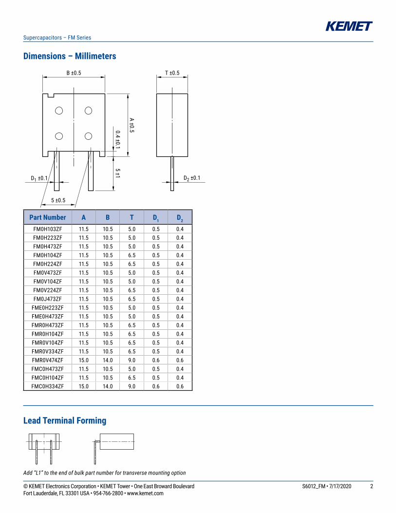
Dimensions – Millimeters
A ±0.5
5 ±10.4 ±0.1
D1 ±0.1 D2 ±0.1
B ±0.5
5 ±0.5
T ±0.5
Part Number A B T D1 D2
FM0H103ZF 11.5 10.5 5.0 0.5 0.4FM0H223ZF 11.5 10.5 5.0 0.5 0.4FM0H473ZF 11.5 10.5 5.0 0.5 0.4FM0H104ZF 11.5 10.5 6.5 0.5 0.4FM0H224ZF 11.5 10.5 6.5 0.5 0.4FM0V473ZF 11.5 10.5 5.0 0.5 0.4FM0V104ZF 11.5 10.5 5.0 0.5 0.4FM0V224ZF 11.5 10.5 6.5 0.5 0.4FM0J473ZF 11.5 10.5 6.5 0.5 0.4
FME0H223ZF 11.5 10.5 5.0 0.5 0.4FME0H473ZF 11.5 10.5 5.0 0.5 0.4FMR0H473ZF 11.5 10.5 6.5 0.5 0.4FMR0H104ZF 11.5 10.5 6.5 0.5 0.4FMR0V104ZF 11.5 10.5 6.5 0.5 0.4FMR0V334ZF 11.5 10.5 6.5 0.5 0.4FMR0V474ZF 15.0 14.0 9.0 0.6 0.6FMC0H473ZF 11.5 10.5 5.0 0.5 0.4FMC0H104ZF 11.5 10.5 6.5 0.5 0.4FMC0H334ZF 15.0 14.0 9.0 0.6 0.6
Lead Terminal Forming
L=2.2 to 5mm
Lead length designation For transverse mounting <L1>
Add “L1” to the end of bulk part number for transverse mounting option
3© KEMET Electronics Corporation • KEMET Tower • One East Broward Boulevard S6012_FM • 7/17/2020Fort Lauderdale, FL 33301 USA • 954-766-2800 • www.kemet.com
Supercapacitors – FM Series
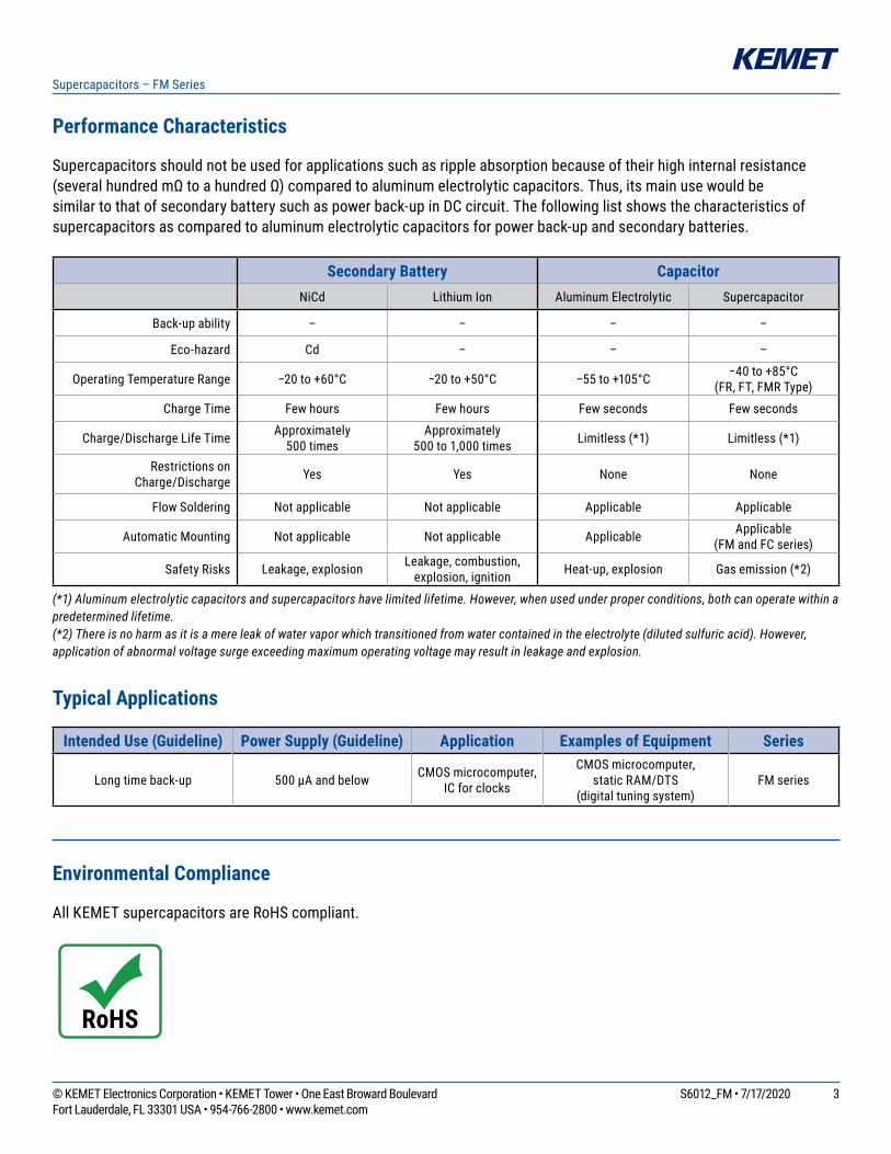
Performance Characteristics
Supercapacitorsshouldnotbeusedforapplicationssuchasrippleabsorptionbecauseoftheirhighinternalresistance(severalhundredmΩtoahundredΩ)comparedtoaluminumelectrolyticcapacitors.Thus,itsmainusewouldbesimilartothatofsecondarybatterysuchaspowerback-upinDCcircuit.Thefollowinglistshowsthecharacteristicsofsupercapacitorsascomparedtoaluminumelectrolyticcapacitorsforpowerback-upandsecondarybatteries.
Secondary Battery CapacitorNiCd Lithium Ion AluminumElectrolytic Supercapacitor
Back-upability – – – –
Eco-hazard Cd – – –
Operating Temperature Range −20to+60°C −20to+50°C −55to+105°C −40to+85°C (FR,FT,FMRType)
Charge Time Few hours Few hours Few seconds Few seconds
Charge/Discharge Life Time Approximately 500 times
Approximately 500 to 1,000 times Limitless(*1) Limitless(*1)
Restrictions on Charge/Discharge Yes Yes None None
Flow Soldering Notapplicable Notapplicable Applicable Applicable
Automatic Mounting Notapplicable Notapplicable Applicable Applicable(FMandFCseries)
SafetyRisks Leakage, explosion Leakage,combustion,explosion, ignition Heat-up, explosion Gasemission(*2)
(*1) Aluminum electrolytic capacitors and supercapacitors have limited lifetime. However, when used under proper conditions, both can operate within a predetermined lifetime.(*2) There is no harm as it is a mere leak of water vapor which transitioned from water contained in the electrolyte (diluted sulfuric acid). However, application of abnormal voltage surge exceeding maximum operating voltage may result in leakage and explosion.
Typical Applications
Intended Use (Guideline) Power Supply (Guideline) Application Examples of Equipment Series
Longtimeback-up 500μAandbelow CMOS microcomputer, IC for clocks
CMOS microcomputer,static RAM/DTS
(digitaltuningsystem)FM series
Environmental Compliance
All KEMET supercapacitors are RoHS compliant.

4© KEMET Electronics Corporation • KEMET Tower • One East Broward Boulevard S6012_FM • 7/17/2020Fort Lauderdale, FL 33301 USA • 954-766-2800 • www.kemet.com
Supercapacitors – FM Series
Table 1 – Ratings & Part Number Reference
Part NumberMaximum Operating
Voltage (VDC)
Nominal CapacitanceMaximum ESR
at 1 kHz (Ω)
Maximum Current at 30 Minutes (mA)
Voltage Holding Characteristic Minimum (V)
Weight (g)Charge
System (F)Discharge System (F)
FM0V473ZF 3.5 0.047 0.06 200 0.042 - 1.3FMR0V104ZF 3.5 0.10 - 50 0.090 - 1.6FM0V104ZF 3.5 0.10 0.13 100 0.090 - 1.3FM0V224ZF 3.5 0.22 0.30 100 0.20 - 1.6FM0H103ZF 5.5 0.01 0.014 300 0.015 4.2 1.3
FME0H223ZF 5.5 0.022 0.028 40 0.033 - 1.3FM0H223ZF 5.5 0.022 0.028 200 0.033 4.2 1.3
FME0H473ZF 5.5 0.047 0.06 20 0.071 - 1.3FMC0H473ZF 5.5 0.047 0.06 100 0.071 4.2 1.3FM0H473ZF 5.5 0.047 0.06 200 0.071 4.2 1.3
FMR0H473ZF 5.5 0.047 0.062 200 0.071 4.2 1.6FMR0H104ZF 5.5 0.10 - 50 0.15 4.2 1.6FMR0V334ZF 3.6 - 0.33 50 0.3 - 1.6FMR0V474ZF 3.6 - 0.47 25 0.42 - 3.5FMC0H104ZF 5.5 0.10 0.13 50 0.15 4.2 1.6FM0H104ZF 5.5 0.10 0.13 100 0.15 4.2 1.6FM0H224ZF 5.5 - 0.22 100 0.33 4.2 1.6
FMC0H334ZF 5.5 - 0.33 25 0.50 4.2 3.5FM0J473ZF 6.5 0.047 0.062 200 0.071 - 1.6

5© KEMET Electronics Corporation • KEMET Tower • One East Broward Boulevard S6012_FM • 7/17/2020Fort Lauderdale, FL 33301 USA • 954-766-2800 • www.kemet.com
Supercapacitors – FM Series
Specifications – All Types Except FMR
Item FM 5.5 V Type, 3.5 V Type, 6.5 V Type, FMC Type FME Type Test Conditions
(conforming to JIS C 5160-1)CategoryTemperatureRange −25°Cto+70°C −25°Cto+70°C
Maximum Operating Voltage 5.5 VDC, 3.5 VDC, 6.5 VDC 5.5 VDC
Capacitance RefertoTable1 RefertoTable1 Refer to “Measurement Conditions”
Capacitance Allowance +80%,−20% +80%,−20% Refer to “Measurement Conditions”
ESR RefertoTable1 RefertoTable1 Measured at 1 kHz, 10 mA; See also “Measurement Conditions”
Current(30minutesvalue) RefertoTable1 RefertoTable1 Refer to “Measurement Conditions”
Surge
Capacitance >90%ofinitialratings >90%ofinitialratings
Surge voltage:
Charge:Discharge:
Numberofcycles:Series resistance:
Discharge resistance:
Temperature:
4.0V(3.5Vtype)6.3V(5.5Vtype)7.4V(6.5Vtype)30 seconds9 minutes 30 seconds1,0000.010F1,500Ω0.022F 560Ω0.047F 300Ω0.068F 240Ω0.10F 150Ω0.22F 56Ω0.33F 51Ω
0Ω70±2°C
ESR ≤120%ofinitialratings ≤120%ofinitialratings
Current(30minutes value) ≤120%ofinitialratings ≤120%ofinitialratings
Appearance Noobviousabnormality Noobviousabnormality
Characteristics in Different Temperature
Capacitance Phase 2
≥50%of initial value Phase
2
≥50%of initial value
Conforms to 4.17Phase 1:Phase 2:Phase 4:Phase 5:Phase 6:
+25±2°C−25±2°C+25±2°C+70±2°C+25±2°C
ESR ≤400%of initial value
≤300%orless than initial value
Capacitance Phase 3
Phase 3ESR
Capacitance
Phase 5
≤200%of initial value
Phase 5
≤150%of initial value
ESR Satisfyinitial ratings
Satisfyinitial ratings
Current(30minutes value) ≤1.5CV(mA) ≤1.5CV(mA)
Capacitance
Phase 6
Within±20%of initial value
Phase 6
Within±20% of initial value
ESR Satisfyinitial ratings
Satisfyinitial ratings
Current(30minutes value)
Satisfyinitial ratings
Satisfyinitial ratings
VibrationResistance
Capacitance
Satisfyinitialratings Satisfyinitialratings
Conforms to 4.13Frequency:
Testing Time: 10 to 55 Hz6 hours
ESR
Current(30minutes value)
Appearance Noobviousabnormality Noobviousabnormality
Solderability Over3/4oftheterminalshouldbecoveredbythenewsolder
Over3/4oftheterminalshouldbecoveredbythenewsolder
Conforms to 4.11Solder temp:Dipping time:
+245±5°C5±0.5 seconds
1.6mmfromthebottomshouldbedipped.
6© KEMET Electronics Corporation • KEMET Tower • One East Broward Boulevard S6012_FM • 7/17/2020Fort Lauderdale, FL 33301 USA • 954-766-2800 • www.kemet.com
Supercapacitors – FM Series
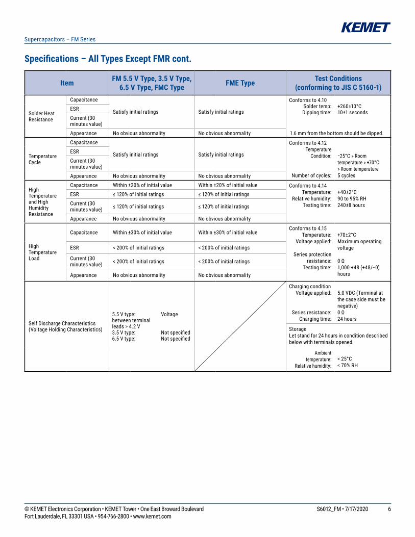
Specifications – All Types Except FMR cont.
Item FM 5.5 V Type, 3.5 V Type, 6.5 V Type, FMC Type FME Type Test Conditions
(conforming to JIS C 5160-1)
Solder Heat Resistance
Capacitance
Satisfyinitialratings Satisfyinitialratings
Conforms to 4.10Solder temp:Dipping time:
+260±10°C10±1 secondsESR
Current(30minutes value)
Appearance Noobviousabnormality Noobviousabnormality 1.6mmfromthebottomshouldbedipped.
Temperature Cycle
Capacitance
Satisfyinitialratings Satisfyinitialratings
Conforms to 4.12Temperature
Condition:
Numberofcycles:
−25°C» Room temperature»+70°C »Roomtemperature5cycles
ESR
Current(30minutes value)
Appearance Noobviousabnormality Noobviousabnormality
High Temperature and High HumidityResistance
Capacitance Within±20%ofinitialvalue Within±20%ofinitialvalue Conforms to 4.14Temperature:
Relativehumidity:Testing time:
+40±2°C90to95%RH240±8 hours
ESR ≤120%ofinitialratings ≤120%ofinitialratings
Current(30minutes value) ≤120%ofinitialratings ≤120%ofinitialratings
Appearance Noobviousabnormality Noobviousabnormality
High Temperature Load
Capacitance Within±30%ofinitialvalue Within±30%ofinitialvalueConforms to 4.15
Temperature: Voltage applied:
Series protection resistance:
Testing time:
+70±2°CMaximum operating voltage
0Ω1,000+48(+48/−0)hours
ESR <200%ofinitialratings <200%ofinitialratings
Current(30minutes value) <200%ofinitialratings <200%ofinitialratings
Appearance Noobviousabnormality Noobviousabnormality
Self Discharge Characteristics (VoltageHoldingCharacteristics)
5.5Vtype: Voltagebetweenterminal leads > 4.2 V3.5Vtype: Notspecified6.5Vtype: Notspecified
Charging conditionVoltage applied:
Series resistance: Charging time:
5.0VDC(Terminalatthecasesidemustbenegative)0Ω24 hours
StorageLetstandfor24hoursinconditiondescribedbelowwithterminalsopened.
Ambienttemperature:
Relativehumidity:<25°C<70%RH
7© KEMET Electronics Corporation • KEMET Tower • One East Broward Boulevard S6012_FM • 7/17/2020Fort Lauderdale, FL 33301 USA • 954-766-2800 • www.kemet.com
Supercapacitors – FM Series
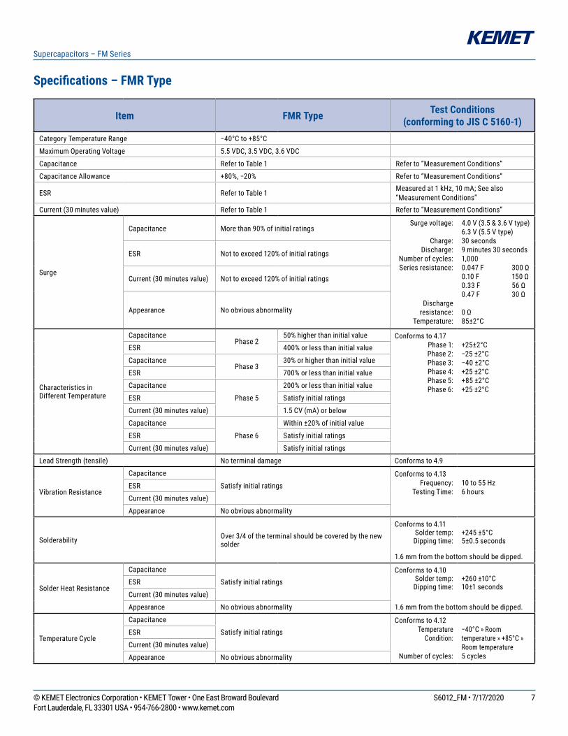
Item FMR Type Test Conditions (conforming to JIS C 5160-1)
CategoryTemperatureRange −40°Cto+85°C
Maximum Operating Voltage 5.5 VDC, 3.5 VDC, 3.6 VDC
Capacitance RefertoTable1 Refer to “Measurement Conditions”
Capacitance Allowance +80%,−20% Refer to “Measurement Conditions”
ESR RefertoTable1 Measured at 1 kHz, 10 mA; See also “Measurement Conditions”
Current(30minutesvalue) RefertoTable1 Refer to “Measurement Conditions”
Surge
Capacitance Morethan90%ofinitialratingsSurge voltage:
Charge:Discharge:
Numberofcycles:Series resistance:
Discharge resistance:
Temperature:
4.0V(3.5&3.6Vtype)6.3V(5.5Vtype)30 seconds9 minutes 30 seconds1,0000.047F 300Ω0.10F 150Ω0.33F 56Ω0.47F 30Ω
0Ω85±2°C
ESR Nottoexceed120%ofinitialratings
Current(30minutesvalue) Nottoexceed120%ofinitialratings
Appearance Noobviousabnormality
Characteristics in Different Temperature
CapacitancePhase 2
50%higherthaninitialvalue Conforms to 4.17Phase 1:Phase 2:Phase 3:Phase 4:Phase 5:Phase 6:
+25±2°C−25±2°C−40±2°C+25±2°C+85±2°C+25±2°C
ESR 400%orlessthaninitialvalue
CapacitancePhase 3
30%orhigherthaninitialvalue
ESR 700%orlessthaninitialvalue
Capacitance
Phase 5
200%orlessthaninitialvalue
ESR Satisfyinitialratings
Current(30minutesvalue) 1.5CV(mA)orbelow
Capacitance
Phase 6
Within±20%ofinitialvalue
ESR Satisfyinitialratings
Current(30minutesvalue) Satisfyinitialratings
LeadStrength(tensile) No terminal damage Conforms to 4.9
VibrationResistance
Capacitance
SatisfyinitialratingsConforms to 4.13
Frequency:Testing Time:
10 to 55 Hz6 hours
ESR
Current(30minutesvalue)
Appearance Noobviousabnormality
Solderability Over3/4oftheterminalshouldbecoveredbythenewsolder
Conforms to 4.11Solder temp:Dipping time:
+245±5°C5±0.5 seconds
1.6mmfromthebottomshouldbedipped.
Solder Heat Resistance
Capacitance
SatisfyinitialratingsConforms to 4.10
Solder temp:Dipping time:
+260±10°C10±1 secondsESR
Current(30minutesvalue)
Appearance Noobviousabnormality 1.6mmfromthebottomshouldbedipped.
TemperatureCycle
Capacitance
SatisfyinitialratingsConforms to 4.12
Temperature Condition:
Numberofcycles:
−40°C»Roomtemperature»+85°C»Room temperature5cycles
ESR
Current(30minutesvalue)
Appearance Noobviousabnormality
Specifications – FMR Type

8© KEMET Electronics Corporation • KEMET Tower • One East Broward Boulevard S6012_FM • 7/17/2020Fort Lauderdale, FL 33301 USA • 954-766-2800 • www.kemet.com
Supercapacitors – FM Series
Specifications – FMR Type cont.
Construction
Leads
Element
MoldingResin
Item FMR Type Test Conditions (conforming to JIS C 5160-1)
High Temperature and HighHumidityResistance
Capacitance Within±20%ofinitialvalue Conforms to 4.14Temperature:
Relativehumidity:Testing time:
+40±2°C90to95%RH240 ±8 hours
ESR Nottoexceed120%ofinitialratings
Current(30minutesvalue) Nottoexceed120%ofinitialratings
Appearance Noobviousabnormality
High Temperature Load
Capacitance Within±30%ofinitialvalueConforms to 4.15
Temperature: Voltage applied:
Series protection resistance:
Testing time:
+85±2°CMaximum operating voltage
0Ω1,000+48(+48/−0)hours
ESR Below200%ofinitialratings
Current(30minutesvalue) Below200%ofinitialratings
Appearance Noobviousabnormality
Self Discharge Characteristics (VoltageHoldingCharacteristics)
5.5Vtype: Voltagebetweenterminalleadshigher than 4.2 V
Charging conditionVoltage applied:
Series resistance: Charging time:
5.0VDC(Terminalatthecasesidemustbenegative)0Ω24 hours
3.5Vtype:3.6Vtype: Notspecified
StorageLetstandfor24hoursinconditiondescribedbelowwithterminalsopened.
Ambienttemperature:
Relativehumidity:
Lowerthan25°CLowerthan70%RH
9© KEMET Electronics Corporation • KEMET Tower • One East Broward Boulevard S6012_FM • 7/17/2020Fort Lauderdale, FL 33301 USA • 954-766-2800 • www.kemet.com
Supercapacitors – FM Series
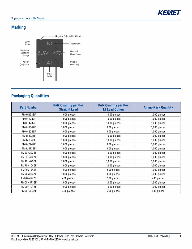
Marking
Trademark
Negative Polarity Identification
MaximumOperating
Voltage
Polarity(Negative)
Polarity(Positive)
SeriesName
DateCode
NominalCapacitance
Packaging Quantities
Part Number Bulk Quantity per BoxStraight Lead
Bulk Quantity per BoxL1 Lead Option Ammo Pack Quantity
FM0H103ZF 1,000 pieces 1,000 pieces 1,000 piecesFM0H223ZF 1,000 pieces 1,000 pieces 1,000 piecesFM0H473ZF 1,000 pieces 1,000 pieces 1,000 piecesFM0H104ZF 1,000 pieces 800 pieces 1,000 piecesFM0H224ZF 1,000 pieces 800 pieces 1,000 piecesFM0V473ZF 1,000 pieces 1,000 pieces 1,000 piecesFM0V104ZF 1,000 pieces 1,000 pieces 1,000 piecesFM0V224ZF 1,000 pieces 800 pieces 1,000 piecesFM0J473ZF 1,000 pieces 800 pieces 1,000 pieces
FME0H223ZF 1,000 pieces 1,000 pieces 1,000 piecesFME0H473ZF 1,000 pieces 1,000 pieces 1,000 piecesFMR0H473ZF 1,000 pieces 1,000 pieces 1,000 piecesFMR0H104ZF 1,000 pieces 1,000 pieces 1,000 piecesFMR0V104ZF 1,000 pieces 800 pieces 1,000 piecesFMR0V334ZF 1,000 pieces 800 pieces 1,000 piecesFMR0V474ZF 400 pieces 300 pieces 400 piecesFMC0H473ZF 1,000 pieces 1,000 pieces 1,000 piecesFMC0H104ZF 1,000 pieces 1,000 pieces 1,000 piecesFMC0H334ZF 400 pieces 300 pieces 400 pieces
10© KEMET Electronics Corporation • KEMET Tower • One East Broward Boulevard S6012_FM • 7/17/2020Fort Lauderdale, FL 33301 USA • 954-766-2800 • www.kemet.com
Supercapacitors – FM Series
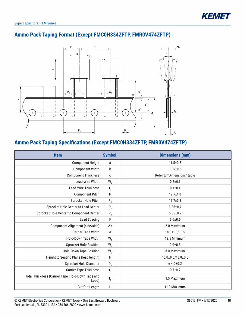
Ammo Pack Taping Format (Except FMC0H334ZFTP, FMR0V474ZFTP)
+– +–
P2
b
P1 F W4
P0 D0
c
t3
t2
t1
∆hP
W1
W0
W
H
L
a
W2
Ammo Pack Taping Specifications (Except FMC0H334ZFTP, FMR0V474ZFTP)
Item Symbol Dimensions (mm)
Component Height a 11.5±0.5
Component Width b 10.5±0.5
Component Thickness c Referto“Dimensions”table
Lead-Wire Width W4 0.5±0.1
Lead-Wire Thickness t3 0.4±0.1
Component Pitch P 12.7±1.0
Sprocket Hole Pitch P0 12.7±0.3
Sprocket Hole Center to Lead Center P1 3.85±0.7
Sprocket Hole Center to Component Center P2 6.35±0.7
Lead Spacing F 5.0±0.5
ComponentAlignment(side/side) ∆h 2.0 Maximum
Carrier Tape Width W 18.0+1.0/−0.5
Hold-Down Tape Width W0 12.5 Minimum
Sprocket Hole Position W1 9.0±0.5
Hold-Down Tape Position W2 3.0 Maximum
HeighttoSeatingPlane(leadlength) H 16.0±0.5/18.0±0.5
Sprocket Hole Diameter D0 ø 4.0±0.2
Carrier Tape Thickness t1 0.7±0.2
TotalThickness(CarrierTape,Hold-DownTapeandLead) t2 1.5 Maximum
Cut Out Length L 11.0 Maximum

11© KEMET Electronics Corporation • KEMET Tower • One East Broward Boulevard S6012_FM • 7/17/2020Fort Lauderdale, FL 33301 USA • 954-766-2800 • www.kemet.com
Supercapacitors – FM Series
Ammo Pack Taping Format (FMC0H334ZFTP, FMR0V474ZFTP)
+– +–
P2
b
P1 F W4
P0 D0
c
t3
t2
t1
∆hP
W1
W0
W
H
L
a
W2
Ammo Pack Taping Specifications (FMC0H334ZFTP, FMR0V474ZFTP)
Item Symbol Dimensions (mm)
Component Height a 15.0±0.5
Component Width b 14.0±0.5
Component Thickness c 9.0±0.5
Lead-Wire Width W4 0.6±0.1
Lead-Wire Thickness t3 0.6±0.1
Component Pitch P 25.4±1.0
Sprocket Hole Pitch P0 12.7±0.3
Sprocket Hole Center to Lead Center P1 3.85±0.7
Sprocket Hole Center to Component Center P2 6.35±0.7
Lead Spacing F 5.0±0.5
ComponentAlignment(side/side) ∆h 2.0 Maximum
Carrier Tape Width W 18.0+1.0/−0.5
Hold-Down Tape Width W0 12.5 Minimum
Sprocket Hole Position W1 9.0±0.5
Hold-Down Tape Position W2 3.0 Maximum
HeighttoSeatingPlane(leadlength) H 16.0±0.5/18.0±0.5
Sprocket Hole Diameter D0 ø 4.0±0.2
Carrier Tape Thickness t1 0.67±0.2
TotalThickness(CarrierTape,Hold-DownTapeandLead) t2 1.7 Maximum
Cut Out Length L 11.0 Maximum

12© KEMET Electronics Corporation • KEMET Tower • One East Broward Boulevard S6012_FM • 7/17/2020Fort Lauderdale, FL 33301 USA • 954-766-2800 • www.kemet.com
Supercapacitors – FM Series
Measurement Conditions
Capacitance (Charge System)Capacitanceiscalculatedfromexpression(9)bymeasuringthechargetimeconstant(τ)ofthecapacitor(C).Priortomeasurement,thecapacitorisdischargedbyshortingbothpinsofthedeviceforatleast30minutes.Inaddition,usethepolarityindicator on the device to determine correct orientation of capacitor for charging.
Eo: 3.0(V) Productwithmaximumoperatingvoltageof3.5V 5.0(V) Productwithmaximumoperatingvoltageof5.5V 6.0(V) Productwithmaximumoperatingvoltageof6.5V 10.0(V)Productwithmaximumoperatingvoltageof11V 12.0(V)Productwithmaximumoperatingvoltageof12Vτ: TimefromstartofcharginguntilVcbecomes0.632Eo(V)(seconds)Rc: Seetablebelow(Ω).
Charge Resistor Selection Guide
Cap FA FE FS FY FR FM, FMEFMR FMC FG,
FGR FGH FT FC, FCS HVFYD FYH0.010 F – – – – – – 5,000Ω – 5,000Ω – – – –0.022 F 1,000Ω – 1,000Ω 2,000Ω 2,000Ω 2,000Ω 2,000Ω – 2,000Ω – – Discharge –0.033 F – – – – – – Discharge – – – – – –0.047 F 1,000Ω 1,000Ω 1,000Ω 2,000Ω 1,000Ω 1,000Ω 2000Ω 1,000Ω 2,000Ω – – – –0.10 F 510Ω 510Ω 510Ω 1,000Ω 510Ω 1,000Ω 1000Ω 1,000Ω 1,000Ω Discharge 510Ω Discharge –
0.22 F 200Ω 200Ω 200Ω 510Ω 510Ω 510Ω 0H: Discharge0V:1000Ω – 1,000Ω Discharge 200Ω Discharge –
0.33 F – – – – – – – Discharge – – – – –0.47 F 100Ω 100Ω 100Ω 200Ω 200Ω 200Ω – – 1,000Ω Discharge 100Ω Discharge –1.0 F 51Ω 51Ω 100Ω 100Ω 100Ω 100Ω – – 510Ω Discharge 100Ω Discharge Discharge1.4 F – – – 200Ω – – – – – – – – –1.5 F – 51Ω – – – – – – 510Ω – – – –2.2 F – – – 100Ω – – – – 200Ω – 51Ω – –2.7 F – – – – – – – – – – – – Discharge3.3 F – – – – – – – – – – 51Ω – –4.7 F – – – – – – – – 100Ω – – – Discharge5.0 F – – 100Ω – – – – – – – – – –5.6 F – – – – – – – – – – 20Ω – –
10.0 F – – – – – – – – – – – – Discharge22.0 F – – – – – – – – – – – – Discharge50.0 F – – – – – – – – – – – – Discharge
100.0 F – – – – – – – – – – – – Discharge200.0 F – – – – – – – – – – – – Discharge
*Capacitance values according to the constant current discharge method.*HV Series capacitance is measured by discharge system.
VcRc
Switch
C+
–Eo
Capacitance: C =
τ(F) (9)
Rc
13© KEMET Electronics Corporation • KEMET Tower • One East Broward Boulevard S6012_FM • 7/17/2020Fort Lauderdale, FL 33301 USA • 954-766-2800 • www.kemet.com
Supercapacitors – FM Series
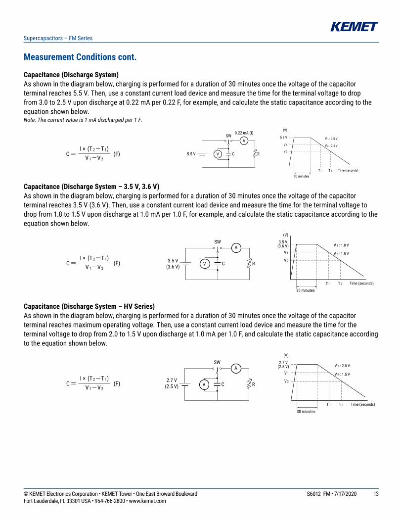
Measurement Conditions cont.
Capacitance (Discharge System)Asshowninthediagrambelow,chargingisperformedforadurationof30minutesoncethevoltageofthecapacitorterminal reaches 5.5 V. Then, use a constant current load device and measure the time for the terminal voltage to drop from 3.0 to 2.5 V upon discharge at 0.22 mA per 0.22 F, for example, and calculate the static capacitance according to the equationshownbelow.Note: The current value is 1 mA discharged per 1 F.
Capacitance (Discharge System – 3.5 V, 3.6 V)Asshowninthediagrambelow,chargingisperformedforadurationof30minutesoncethevoltageofthecapacitorterminalreaches3.5V(3.6V).Then,useaconstantcurrentloaddeviceandmeasurethetimefortheterminalvoltagetodrop from 1.8 to 1.5 V upon discharge at 1.0 mA per 1.0 F, for example, and calculate the static capacitance according to the equationshownbelow.
Capacitance (Discharge System – HV Series)Asshowninthediagrambelow,chargingisperformedforadurationof30minutesoncethevoltageofthecapacitorterminal reaches maximum operating voltage. Then, use a constant current load device and measure the time for the terminal voltage to drop from 2.0 to 1.5 V upon discharge at 1.0 mA per 1.0 F, and calculate the static capacitance according totheequationshownbelow.
A
V C R5.5 V
0.22 mA (I)SW
30 minutesT1 T2
V 2 : 2.5 V
V 1 : 3.0 V5.5 V
(V)
V 1
V 2
Time (seconds)
C= (F)I × (T 2-T1)
V 1-V 2
A
V C R3.5 V(3.6 V)
SW
30 minutesT1 T2
V 2 : 1.5 V
V 1 : 1.8 V3.5 V
(3.6 V)
(V)
V 1
V 2
Time (seconds)
C= (F)I × (T 2-T1)
V 1-V 2
A
V C R2.7 V
(2.5 V)
SW
30 minutesT1 T2
V 2 : 1.5 V
V 1 : 2.0 V2.7 V
(2.5 V)
(V)
V 1
V 2
Time (seconds)
C= (F)I × (T 2-T1)
V 1-V 2

14© KEMET Electronics Corporation • KEMET Tower • One East Broward Boulevard S6012_FM • 7/17/2020Fort Lauderdale, FL 33301 USA • 954-766-2800 • www.kemet.com
Supercapacitors – FM Series
Measurement Conditions cont.
Equivalent Series Resistance (ESR)ESRshallbecalculatedfromtheequationbelow.
Current (at 30 minutes after charging)Currentshallbecalculatedfromtheequationbelow.Priortomeasurement,bothleadterminalsmustbeshort-circuitedfora minimum of 30 minutes. The lead terminal connected to the metal can case is connected to the negative side of the power supply.
Eo: 2.5VDC(HVSeries50F) 2.7VDC(HVSeriesexcept50F) 3.0VDC(3.5Vtype) 3.6VDC(3.6Vtype) 5.0VDC(5.5Vtype) 6.0VDC(6.5Vtype) 10.0VDC(11Vtype) 12.0VDC(12Vtype)
Rc: 1,000Ω(0.01F,0.022F,0.047F) 100Ω(0.10F,0.22F,0.33F,0.47F) 10Ω(1.0F,1.4F,1.5F,2.2F,3.3F,4.7F,5.6F) 2.2Ω(HVSeries)However,FSSeres11Vtypeand12Vtype 100Ω0.47F,1.0F 10Ω5.0F
Self-Discharge Characteristic (0H – 5.5 V Products)Theself-dischargecharacteristicismeasuredbychargingavoltageof5.0VDC(chargeprotectionresistance:0Ω)accordingtothecapacitorpolarityfor24hours,thenreleasingbetweenthepinsfor24hoursandmeasuringthepin-to-pinvoltage.Thetestshouldbecarriedoutinanenvironmentwithanambienttemperatureof25°Corbelowandrelativehumidityof70%RHorbelow.Thesolderingischecked.
4. Dismantling Thereisasmallamountofelectrolytestoredwithinthecapacitor.Donotattempttodismantleasdirectskincontactwiththeelectrolytewillcauseburning.Thisproductshouldbetreatedasindustrialwasteandnotisnottobedisposedofbyfire.
Current = (A)V R
R C C
SW
R C
E O +
-
V R
ESR = ( Ω )V C
0.01 C
10mA
V Cf:1kHz

15© KEMET Electronics Corporation • KEMET Tower • One East Broward Boulevard S6012_FM • 7/17/2020Fort Lauderdale, FL 33301 USA • 954-766-2800 • www.kemet.com
Supercapacitors – FM Series
Notes on Using Supercapacitors or Electric Double-Layer Capacitors (EDLCs)
1. Circuitry Design1.1 Useful lifeTheFCSeriesSupercapacitor(EDLC)usesanelectrolyteinasealedcontainer.Waterintheelectrolytecanevaporatewhileinuseoverlongperiodsoftimeathightemperatures,thusreducingelectrostaticcapacitywhichinturnwillcreategreaterinternalresistance.Thecharacteristicsofthesupercapacitorcanvarygreatlydependingontheenvironmentinwhichitisused.Basicbreakdownmodeisanopenmodeduetoincreasedinternalresistance.
1.2FailrateinthefieldBasedonfielddata,thefailrateiscalculatedatapproximately0.006Fit.Weestimatethatunreportedfailuresaretentimesthisamount.Therefore,weassumethatthefailrateisbelow0.06Fit.
1.3ExceedingmaximumusablevoltagePerformancemaybecompromisedandinsomecasesleakageordamagemayoccurifappliedvoltageexceedsmaximum working voltage.
1.4Useofcapacitorasasmoothingcapacitor(rippleabsorption)Assupercapacitorscontainahighlevelofinternalresistance,theyarenotrecommendedforuseassmoothingcapacitorsinelectricalcircuits.Performancemaybecompromisedand,insomecases,leakageordamagemayoccurifasupercapacitorisusedinrippleabsorption.
1.5 Series connectionsAsappliedvoltagebalancetoeachsupercapacitorislostwhenusedinseriesconnection,excessvoltagemaybeappliedtosomesupercapacitors,whichwillnotonlynegativelyaffectitsperformancebutmayalsocauseleakageand/ordamage.Allowamplemarginformaximumvoltageorattachacircuitforapplyingequalvoltagetoeachsupercapacitor(partialpressureresistor/voltagedivider)whenusingsupercapacitorsinseriesconnection.Also,arrangesupercapacitorssothatthetemperaturebetweeneachcapacitorwillnotvary.
1.6CasePolarityThesupercapacitorismanufacturedsothattheterminalontheoutercaseisnegative(-).Alignthe(-)symbolduringuse.Eventhoughdischarginghasbeencarriedoutpriortoshipping,anyresidualelectricalchargemaynegativelyaffectother parts.
1.7 Use next to heat emittersUsefullifeofthesupercapacitorwillbesignificantlyaffectedifusednearheatemittingitems(coils,powertransistorsandposistors,etc.)wherethesupercapacitoritselfmaybecomeheated.
1.8 Usage environment Thisdevicecannotbeusedinanyacidic,alkalineorsimilartypeofenvironment.
16© KEMET Electronics Corporation • KEMET Tower • One East Broward Boulevard S6012_FM • 7/17/2020Fort Lauderdale, FL 33301 USA • 954-766-2800 • www.kemet.com
Supercapacitors – FM Series
Notes on Using Supercapacitors or Electric Double-Layer Capacitors (EDLCs) cont.
2. Mounting2.1MountingontoareflowfurnaceExceptfortheFCseries,itisnotpossibletomountthiscapacitorontoanIR/VPSreflowfurnace.Donotimmersethecapacitor into a soldering dip tank.
2.2 Flow soldering conditionsKeepsolderunder260°Candsolderingtimetowithin10secondswhenusingtheflowautomaticsolderingmethod.(ExceptfortheFCandHVseries)
2.3 Installation using a soldering ironCaremustbetakentopreventthesolderingironfromtouchingotherpartswhensoldering.Keepthetipofthesolderingironunder400°Candsolderingtimetowithin3seconds.Alwaysmakesurethatthetemperatureofthetipiscontrolled.Internalcapacitorresistanceislikelytoincreaseiftheterminalsareoverheated.
2.4 Lead terminal processingDonotattempttobendorpolishthecapacitorterminalswithsandpaper,etc.Solderingmaynotbepossibleifthemetallic plating is removed from the top of the terminals.
2.5 Cleaning, Coating, and Potting ExceptfortheFMseries,cleaning,coatingandpottingmustnotbecarriedout.ConsultKEMETifthistypeofprocedureisnecessary.Terminalsshouldbedriedatlessthanthemaximumoperatingtemperatureaftercleaning.
3. Storage3.1TemperatureandhumidityMakesurethatthesupercapacitorisstoredaccordingtothefollowingconditions:Temperature:5–35°C(Standard25°C),Humidity:20–70%(Standard:50%).Donotallowthebuildupofcondensationthroughsuddentemperaturechange.
3.2 Environment conditionsMakesuretherearenocorrosivegassessuchassulfurdioxide,aspenetrationoftheleadterminalsispossible.Alwaysstorethisiteminanareawithlowdustanddirtlevels.Makesurethatthepackagingwillnotbedeformedthroughheavyloading,movementand/orknocks.Keepoutofdirectsunlightandawayfromradiation,staticelectricityandmagneticfields.
3.3 Maximum storage periodThisitemmaybestoreduptooneyearfromthedateofdeliveryifstoredattheconditionsstatedabove.
17© KEMET Electronics Corporation • KEMET Tower • One East Broward Boulevard S6012_FM • 7/17/2020Fort Lauderdale, FL 33301 USA • 954-766-2800 • www.kemet.com
Supercapacitors – FM Series
KEMET Electronics Corporation Sales Offi ces
Foracompletelistofourglobalsalesoffices,pleasevisitwww.kemet.com/sales.
DisclaimerAllproductspecifications,statements,informationanddata(collectively,the“Information”)inthisdatasheetaresubjecttochange.ThecustomerisresponsibleforcheckingandverifyingtheextenttowhichtheInformationcontainedinthispublicationisapplicabletoanorderatthetimetheorderisplaced.AllInformationgivenhereinisbelievedtobeaccurateandreliable,butitispresentedwithoutguarantee,warranty,orresponsibilityofanykind,expressedorimplied.
StatementsofsuitabilityforcertainapplicationsarebasedonKEMETElectronicsCorporation’s(“KEMET”)knowledgeoftypicaloperatingconditionsforsuchapplications,butarenotintendedtoconstitute–andKEMETspecificallydisclaims–anywarrantyconcerningsuitabilityforaspecificcustomerapplicationoruse.TheInformationisintendedforuseonlybycustomerswhohavetherequisiteexperienceandcapabilitytodeterminethecorrectproductsfortheirapplication.AnytechnicaladviceinferredfromthisInformationorotherwiseprovidedbyKEMETwithreferencetotheuseofKEMET’sproductsisgivengratis,andKEMETassumesnoobligationorliabilityfortheadvicegivenorresultsobtained.
AlthoughKEMETdesignsandmanufacturesitsproductstothemoststringentqualityandsafetystandards,giventhecurrentstateoftheart,isolatedcomponentfailuresmaystilloccur.Accordingly,customerapplicationswhichrequireahighdegreeofreliabilityorsafetyshouldemploysuitabledesignsorothersafeguards(suchasinstallationofprotectivecircuitryorredundancies)inordertoensurethatthefailureofanelectricalcomponentdoesnotresultinariskofpersonalinjuryorpropertydamage.
Althoughallproduct–relatedwarnings,cautionsandnotesmustbeobserved,thecustomershouldnotassumethatallsafetymeasuresareindictedorthatothermeasuresmaynotberequired.
WhenprovidingKEMETproductsandtechnologiescontainedhereintoothercountries,thecustomermustabidebytheproceduresandprovisionsstipulatedinallapplicableexportlawsandregulations,includingwithoutlimitationtheInternationalTrafficinArmsRegulations(ITAR),theUSExportAdministrationRegulations(EAR)andtheJapanForeignExchangeandForeignTradeAct.
KEMET is a registered trademark of KEMET Electronics Corporation.