super slim heavy - dynamics automation · new type4 sil3 category4 ple maximum safety standard...
TRANSCRIPT
NEW
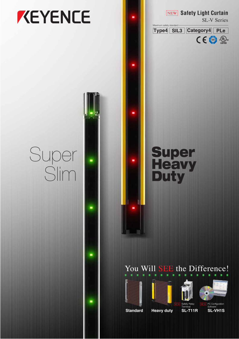
PLeType4 Category4SIL3Maximum safety standard
Heavy dutyStandard
NEW
Safety Relay Terminal
SL-T11R
SuperSlim
SuperHeavyDuty
You Will SEE the Difference!
NEW PC Configuration Software
SL-VH1S
Safety Light CurtainSL-V Series
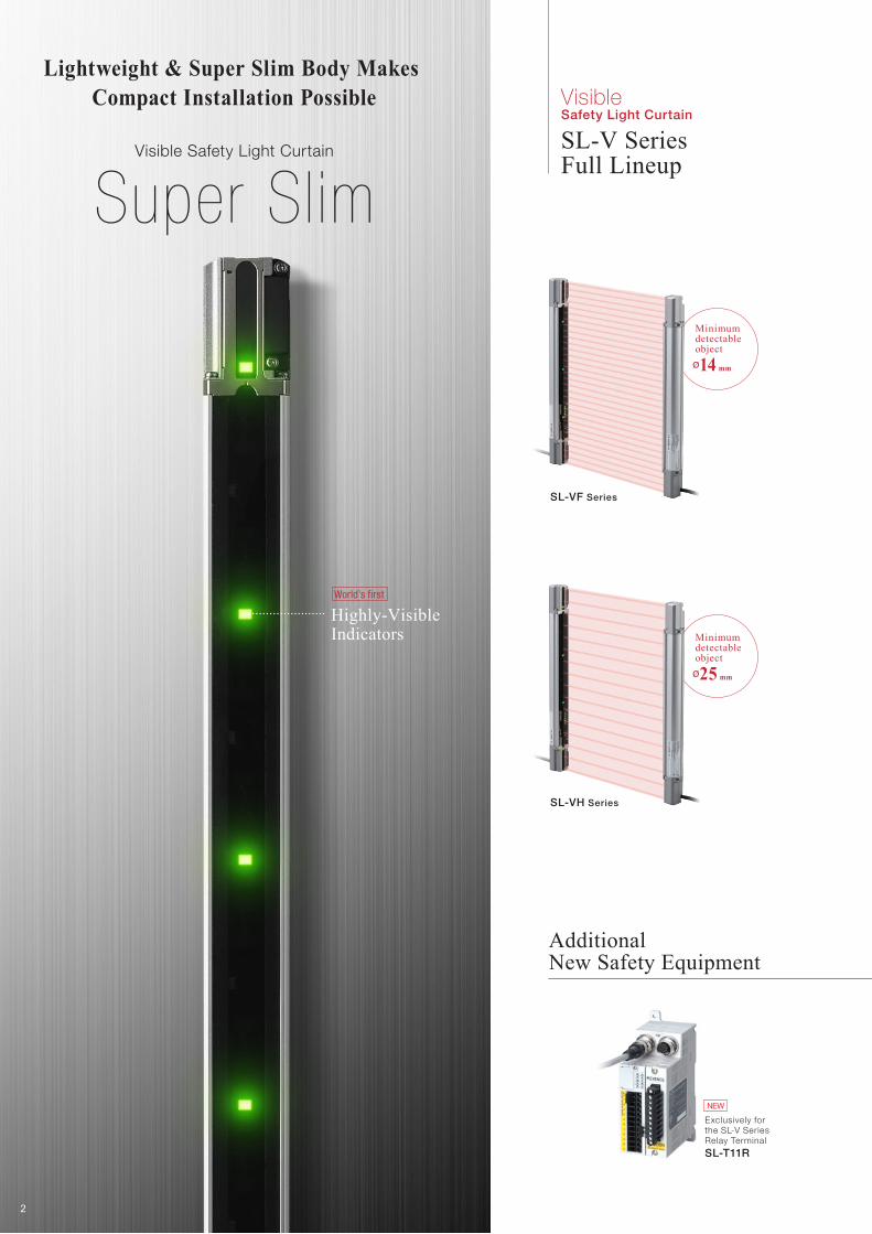
SL-VF Series
SL-VH Series
World’s first
NEW
Exclusively for the SL-V SeriesRelay Terminal
SL-T11R
SL-V SeriesFull Lineup
Visible Safety Light Curtain
Minimum detectable objectø14 mm
Minimum detectable objectø25 mm
Additional New Safety Equipment
Highly-Visible Indicators
Lightweight & Super Slim Body Makes Compact Installation Possible
Visible Safety Light Curtain
Super Slim
2

SL-VFM Series
SL-VHM Series
NEW
No damage from shock
World’s first
Minimum detectable objectø25 mm
Minimum detectable objectø14 mm
Designed for use in tough environments
Highly Visible Indicators
The SL-V Series meets IP67 standards without the need for any additional accessories
The SL-V Series conforms to IP65 and IP67 based on IEC/JIS standards
This model can be used in places where workpieces often strike the unit.
Visible Safety Light Curtain
Super Heavy Duty
NEWNEW
NEWPC Configuration Software
SL-VH1SUSB Cable
OP-51580(Include with the SL-V1UB)
Interface Unit
SL-V1UB
3
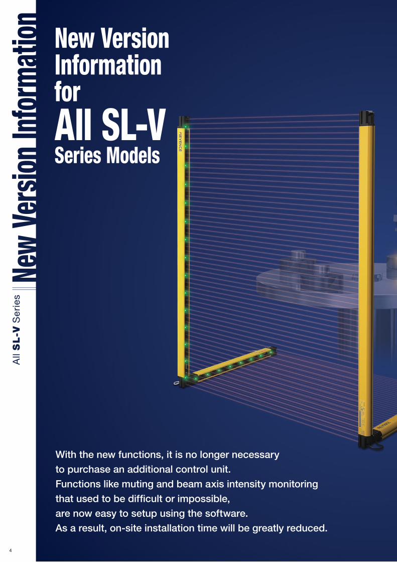
New Version Information for All SL-V Series Models
With the new functions, it is no longer necessary
to purchase an additional control unit.
Functions like muting and beam axis intensity monitoring
that used to be difficult or impossible,
are now easy to setup using the software.
As a result, on-site installation time will be greatly reduced.
4

Fixed Blanking function
Floating Blanking function
Programmable Muting allows the user to customise what parts of the
safety curtain are suspended. Up to three different clearance heights
can be programmed so that the user can easily pass different height
parts while maintaining maximum safety.
This function is used when an
obstacle is always within the
detection area. It makes it possible
to operate a safety light curtain
normally even with an obstacle
present.
This function is used when an
obstacle moves within the
detection area. The output turns
off only if the light is blocked in
more optical axes than the set
number.
Clearance height 1 (The height of the work piece : low)
Clearance height 2 (The height of the work piece : high)
Programmable Muting function
5

❙ Monitor received light intensity of beam axesIt gives the user a visual indication of
beam strength for alignment,
troubleshooting, or initial setup.
It can be used to choose which beams
are used for Muting and Blanking
functions with a PC.
❙ Precisely configure the Muting function
❙ Customise the Highly-Visible Indicators ❙ Configure the Interlock function
The Configuration Software Makes it Possible to-
Easily configure how to reset the light curtain(Interlock
function) under the following two conditions.
-Upon startup: Automatic or Manual
-After an obstruction: Automatic or Manual
❙ Configure the Override functionThe SL-VH1S software can be used to adjust the time
limit of the Override function from the default 60
seconds to as much as 15 minutes.
It allows the operator to select how the Highly-Visible
Indicators spanning the whole curtain will light or flash and
what colour they will be for different conditions. This helps the
user to see the current operating status of the safety light
curtain.
The EDM makes it possible to monitor external devices
such as contactors. The SL-V configuration software
(SL-VH1S) allows the user to select whether or not to use
the EDM function and to select permissible times for it.
❙ Configure the EDM function
The SL-VH1S
Makes It Possible to
Reduce The On-Site Installation Time!
PC configuration software
Required System Environment
USB cableOP-51580(Include with the SL-V1UB)
Interface unit SL-V1UB
safety light curtainThe SL-V Series
Connection cable
SL-VH1S
6
NEW
NEW
NEW
Space-saving design
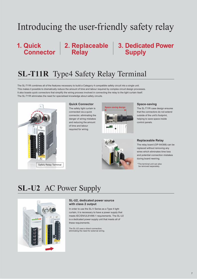
The SL-T11R combines all of the features necessary to build a Category 4 compatible safety circuit into a single unit.
This makes it possible to dramatically reduce the amount of time and labour required by complex circuit design processes.
It also boasts quick connectors that simplify the wiring process involved in connecting the relay to the light curtain itself.
The SL-T11R eliminates the need for specialised knowledge about safety circuits.
The safety light curtain is
connected via a quick
connector, eliminating the
danger of wiring mistakes
and reducing the amount
of time and labour
required for wiring.
The SL-T11R case design ensures
that the connectors do not extend
outside of the unit's footprint,
helping to save space inside
control panels.
Safety Relay Terminal
1. Quick Connector
3. Dedicated Power Supply
2. Replaceable Relay
The relay board (OP-84388) can be
replaced without removing any
wires which eliminates time loss
and potential connection mistakes
during board rewiring.
*The terminal unit can also be removed separately.
SL-U2 AC Power Supply
The SL-U2 uses a direct connection, eliminating the need for external wiring.
In order to use the SL-V Series as a Type 4 light
curtain, it is necessary to have a power supply that
meets IEC/EN/UL61496-1 requirements. The SL-U2
is a dedicated power supply unit that meets all of
these requirements.
Introducing the user-friendly safety relay
SL-T11R Type4 Safety Relay Terminal
Quick Connector Space-saving
Replaceable Relay
SL-U2, dedicated power source with class 2 output
7

For safety and efficiency in the workplace
Introducing a safety light curtain completely focused on visibility
[EDM function, muting function]
1 Visible/Identifiable Indicator
SL-V
Quickly recognise the status of the safety light curtain
2 Edge-to-Edge ConstructionInstallation style that fits the setup with no dead zone
3 Built-in Safety Controller FunctionReduce No. of parts and mounting processes
8
Fine-tune
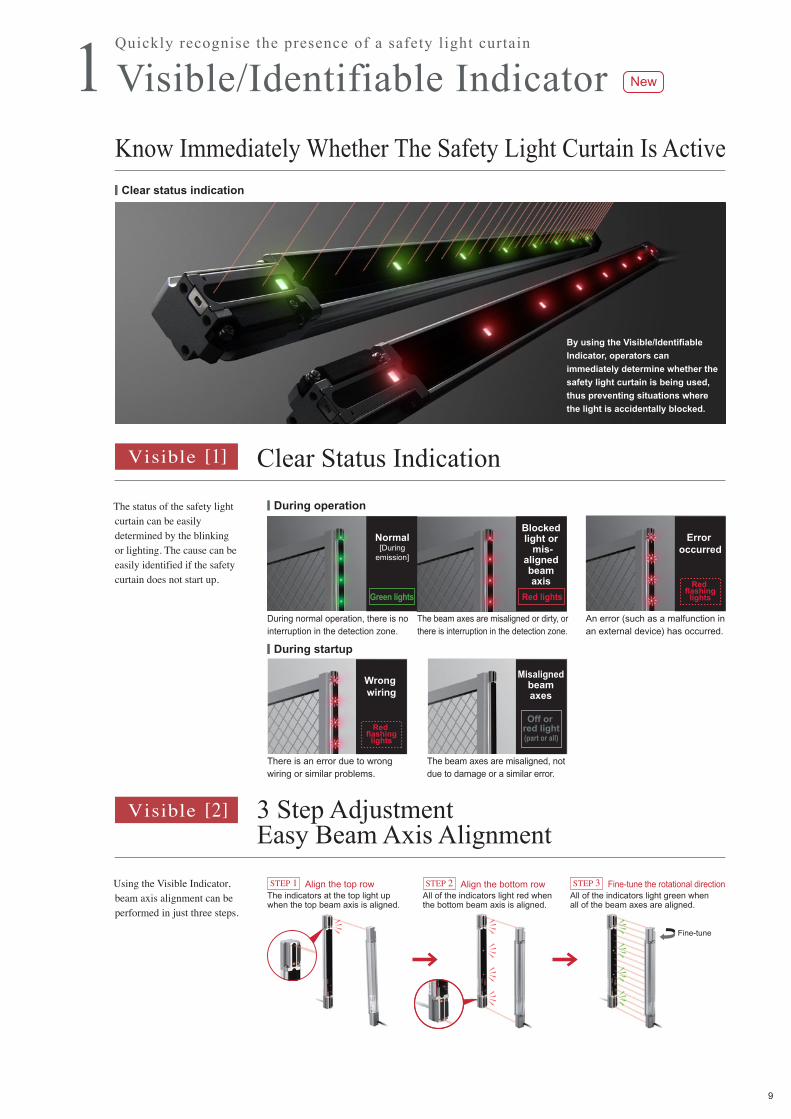
Know Immediately Whether The Safety Light Curtain Is Active
The status of the safety light curtain can be easily determined by the blinking or lighting. The cause can be easily identified if the safety curtain does not start up.
Using the Visible Indicator, beam axis alignment can be performed in just three steps.
During operation
Clear status indication
During startup
Red lights
Clear Status IndicationVisible [1]
3 Step AdjustmentEasy Beam Axis Alignment
Visible [2]
Green lights
Off or red light(part or all)
Error occurred
Red flashing
lights
Wrong wiring
Red flashing
lights
1 Visible/Identifiable IndicatorQuickly recognise the presence of a safety light curtain
New
Align the bottom rowSTEP 2Align the top rowSTEP 1 Fine-tune the rotational directionSTEP 3
There is an error due to wrong wiring or similar problems.
The beam axes are misaligned, not due to damage or a similar error.
During normal operation, there is no interruption in the detection zone.
An error (such as a malfunction in an external device) has occurred.
The beam axes are misaligned or dirty, or there is interruption in the detection zone.
The indicators at the top light up when the top beam axis is aligned.
All of the indicators light red when the bottom beam axis is aligned.
All of the indicators light green when all of the beam axes are aligned.
Blocked light or
mis-aligned beam axis
Normal[During
emission]
Misaligned beam axes
By using the Visible/Identifiable
Indicator, operators can
immediately determine whether the
safety light curtain is being used,
thus preventing situations where
the light is accidentally blocked.
9
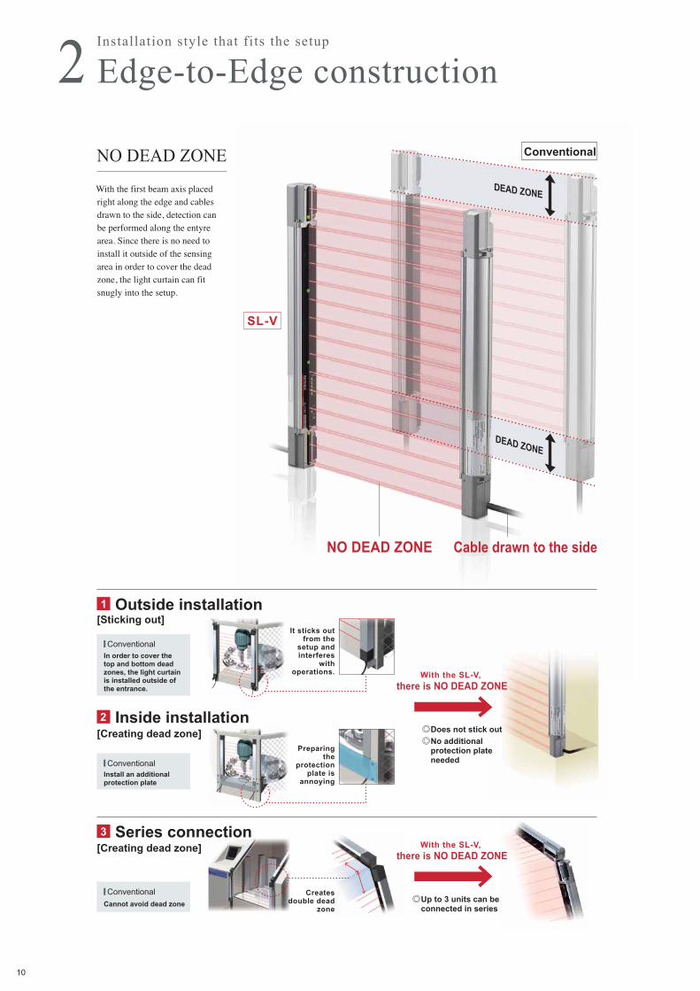
2 Edge-to-Edge construction
Outside installation
� Conventional
1
Inside installation2
Series connection3
� ConventionalCannot avoid dead zone
� ConventionalIn order to cover the top and bottom dead zones, the light curtain is installed outside of the entrance.
Install an additional protection plate
With the SL-V, there is NO DEAD ZONE
With the SL-V, there is NO DEAD ZONE
[Creating dead zone]
[Creating dead zone]
[Sticking out]
With the first beam axis placed right along the edge and cables drawn to the side, detection can be performed along the entyre area. Since there is no need to install it outside of the sensing area in order to cover the dead zone, the light curtain can fit snugly into the setup.
Conventional
DEAD ZONE
NO DEAD ZONE
DEAD ZONE
Cable drawn to the side
SL-V
Installation style that fits the setup
NO DEAD ZONE
Does not stick outNo additional protection plate needed
Up to 3 units can be connected in series
It sticks out from the
setup and interferes
with operations.
Preparing the
protection plate is
annoying
Creates double dead
zone
10
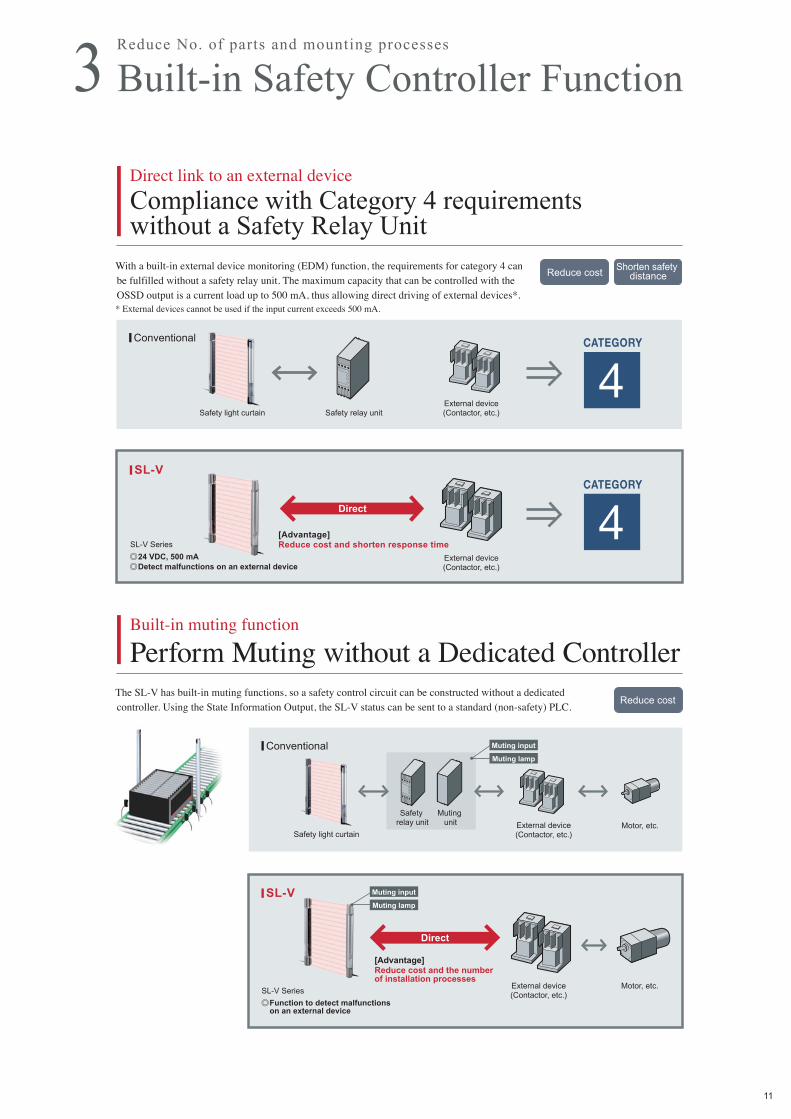
With a built-in external device monitoring (EDM) function, the requirements for category 4 can be fulfilled without a safety relay unit. The maximum capacity that can be controlled with the OSSD output is a current load up to 500 mA, thus allowing direct driving of external devices*. * External devices cannot be used if the input current exceeds 500 mA.
The SL-V has built-in muting functions, so a safety control circuit can be constructed without a dedicated controller. Using the State Information Output, the SL-V status can be sent to a standard (non-safety) PLC.
Reduce cost
Reduce costShorten safety
distance
Safety light curtain Safety relay unitExternal device(Contactor, etc.)
External device(Contactor, etc.)
SL-V Series
Direct
Direct
Conventional
SL-V
Conventional
SL-V
CATEGORY
4
CATEGORY
4
External device(Contactor, etc.)Safety light curtain
Motor, etc.
Muting unit
Safety relay unit
Muting lamp
Muting input
Muting lamp
Muting input
External device(Contactor, etc.)
Motor, etc.SL-V Series
[Advantage] Reduce cost and shorten response time
Direct link to an external device
Compliance with Category 4 requirements without a Safety Relay Unit
Built-in muting function
Perform Muting without a Dedicated Controller
3 Built-in Safety Controller FunctionReduce No. of parts and mounting processes
24 VDC, 500 mADetect malfunctions on an external device
Function to detect malfunctions on an external device
[Advantage] Reduce cost and the number of installation processes
11

Improved upon the demands of electricity supervisors to make the safety light curtain easier to use
Distinguish between safety output off and error off
Separate Alert Output
Send the type of error or muting state to a PLC
State Information Output
Many operators wanted a function that would not just simply turn the safety light curtain on or off, but instead clearly indicate the error*. In response to this request, the alert output (lockout output) can be used additionally. The warning indicator lights up only when there is an error.*Welding or disconnection of relays in the external device, or sensor damage etc.
This function is a function to inform the PLC or other external device (non-safety-related device) of the current state of the safety light curtain. The current state can be identified in real time, so the State Information can be displayed on a touch panel and the state history saved.
Blocked lightOFF
ErrorOFF
Conventional output After improvement
OSSDOFF
Blocked lightOFF
ErrorOFF
OSSDOFF
ErrorOFF
State Information output has two modes: Normal mode (default) and Simple mode.
Red flashinglights
Safety output turned off
due to error
Lights only when there is an error in the lockout output
In addition to the OSSD output, Error OFF can be output additionally.
NEW
NewError cause
analysisControl interlock
SL-V Series
[ Ex. of State Information Output ]
Muting.
Error occurred, external device is damaged.
Error on the muting lamp.
Normal operation.A touch panel
instantaneously shows
the cause of an error.
Outputs the current status to an external device
I/O monitoring function: Checks whether the wiring is performed correctly.
AUX (auxiliary output): Auxiliary output performs the same operations as the OSSD output.
Wait (Stop) input: A signal from an external device causes forcible OSSD-OFF.
Useful input/output functions are also included for startup and maintenance (non-safty-related function).
Muting,Workpiece is
passing through.
12
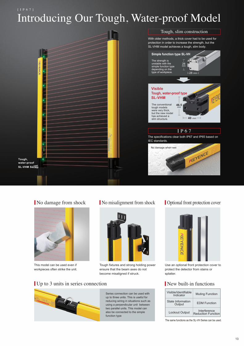
Introducing Our Tough, Water-proof Model
The same functions as the SL-VH Series can be used.
Up to 3 units in series connection
No damage from shock No misalignment from shock Optional front protection cover
New built-in functions
Visible/IdentifiableIndicator Muting Function
State Information Output EDM Function
Lockout Output InterferenceReduction Function
SL-VHM Series
Tough, water-proof
Tough, slim construction
I P 6 7
VisibleTough, water-proof typeSL-VHM
Simple function type SL-VH
No damage when wet
40 mm
46.5mm
28 mm
26mm
[ I P 6 7 ]
With older methods, a thick cover had to be used for protection in order to increase the strength, but the SL-VHM model achieves a tough, slim body.
The strength is unstable with the simple function type depending on the type of workpiece.
The conventional tough models were very thick, but the new model has achieved a slim structure.
This model can be used even if workpieces often strike the unit.
Tough fixtures and strong holding power ensure that the beam axes do not become misaligned if struck.
Use an optional front protection cover to protect the detector from stains or splatter.
Series connection can be used with up to three units. This is useful for reducing wiring in situations such as using a perpendicular unit between two parallel units. This model can also be connected to the simple function type
The specifications clear both IP67 and IP65 based on IEC standards.
13

Selecting a Safety Light CurtainUse the following steps to help select the optimum SL-V Series model according to your situation.
*This step is optional.
*This step is optional.
Select the model
Select the detection capability
Select the length
Select the mounting brackets
Select the cable
Select the controller
Select the PC Configuration Software
Select the protection options if necessary
Light Curtain
mounting bracket
cable
protection options
controller
PC Configuration Software
SL-V Series LINE-UP
1 2 3step
4step
5step
6step
7step
8step
Finger DetectionSL-VF SeriesDetection capabilityø14 mm
Hand DetectionSL-VH SeriesDetection capabilityø25 mm
Finger DetectionTough, water-proofSL-VFM SeriesDetection capabilityø14 mm
Hand DetectionTough, water-proofSL-VHM SeriesDetection capabilityø25 mm
Type 4 Safety Relay Teerminal dedicated for SL-VSL-T11R
protection bar front protection cover
step
1step
2step
3step
4step
5step
6step
7step
8
*This step is optional.
PC Configuration Software SL-VH1S
Interface Unit SL-V1UB
USB Cable OP-51580(Include with the SL-V1UB)
14

Select the detection capability for the model
Simple function typeFor a normal environment
Select the detection capability (ø14/ø25 mm).
Select the type of model
Only if “Simple function type” was selected in step 1.
Select the value according to the distance from the source of the hazard.
Select a simple function type or tough, water-proof type depending on the operating environment.
Go to step 2.
Tough, water-proof typeFor good operations under shock or wet environments
The only available detection capability is ø25 mm.
Go to step 2.
Detection capability: ø14 mm (Detection for a finger)
For a short distance to the hazard source
Intrusion detection
Beam axis pitch of 10 mm. This is the safest type available.
For simple function type Go to step 3.
For tough, waterproof type Go to step 3: SL-VFM.
For simple function type
For tough, waterproof type Go to step 3: SL-VHM.
Detection capability: ø25 mm (Detection for a hand)
For the most widely used, standard type
Beam axis pitch of 20 mm.
Go to step 3.
step 1
step 2
5 7 864321step
Intrusion detection
15

SL-VH Series[Detection capability: ø25 mm]
SL-VF Series[Detection capability: ø14 mm]
Beam axis pitch
20 mm
Detection capability
ø25 mm
Beam axis pitch
10 mm
Detection capability
ø14 mm
[ Selecting a Safety Light Curtain ]
If "ø14 mm (detection for a finger)" was selected in step 2
If "ø25 mm (detection for a hand)" was selected in step 2
Go to step 4.
Go to step 4.
Select the length of the model
Select the necessary length from the specifications chart for the series suggested by step 1 and step 2.
step 3
Select the length. The item to the left of the selected length represents the model forthe appropriate safety light curtain.
Select the length. The item to the left of the selected length represents the model forthe appropriate safety light curtain.
Model
SL-V08H
SL-V12H
SL-V16H
SL-V20H
SL-V24H
SL-V28H
SL-V32H
SL-V36H
SL-V40H
SL-V44H
SL-V48H
SL-V52H
SL-V56H
SL-V60H
SL-V64H
SL-V72H
SL-V80H
SL-V88H
SL-V96H
SL-V104H
SL-V112H
SL-V120H
No. of axes
8
12
16
20
24
28
32
36
40
44
48
52
56
60
64
72
80
88
96
104
112
120
Length (mm)
150
230
310
390
470
550
630
710
790
870
950
1030
1110
1190
1270
1430
1590
1750
1910
2070
2230
2390
Detection height (mm)
140
220
300
380
460
540
620
700
780
860
940
1020
1100
1180
1260
1420
1580
1740
1900
2060
2220
2380
Protection height (mm)
185
265
345
425
505
585
665
745
825
905
985
1065
1145
1225
1305
1465
1625
1785
1945
2105
2265
2425
Operating distance (m)
0.1 to 9
0.1 to 7
Model
SL-V23F
SL-V31F
SL-V39F
SL-V47F
SL-V55F
SL-V63F
SL-V71F
SL-V79F
SL-V87F
SL-V95F
SL-V103F
SL-V111F
SL-V119F
SL-V127F
No. of axes
23
31
39
47
55
63
71
79
87
95
103
111
119
127
Length (mm)
230
310
390
470
550
630
710
790
870
950
1030
1110
1190
1270
Detection height (mm)
220
300
380
460
540
620
700
780
860
940
1020
1100
1180
1260
Protection height (mm)
244
324
404
484
564
644
724
804
884
964
1044
1124
1204
1284
Operating distance (m)
0.1 to 7
Le
ng
thL
en
gth
16
Beam axis pitch
40 mm
Detection capability
ø45 mm
SL-VL Series[Detection capability: ø45 mm]
Limb detection model is also available.[SL-VL Series] For more information about the model and specifications, contact your nearest KEYENCE office.

SL-VHM Series[Tough, water-proof type.Detection capability: ø25 mm]
Understanding the model name
Series nameNo. of beam axes: 2 or 3 digit number. Ex: 08 = 8 axes, 64 = 64 axesDetection capability: F: ø14 mm detection type, H: ø25 mm detection typeSpecial type: Unmarked: Simple function type, M: Tough, water-proof type
SL-V 12 H M1
12
3
4
2 3 4
Meaning of each item Detection capability
Protection height is the
range of protection when
the detection capability
protrudes from the
detection height.
a: Beam axis pitch
b: Beam axis band
c: Detection capabilitya
b
c
Detection height
Length
Beam axis pitch
20 mm
Detection capability
ø25 mm
Beam axis pitch
10 mm
Detection capability
ø14 mm
If "Tough, water-proof type" was selected in step 1
Protection height
Select the length. The item to the left of the selected length represents the model forthe appropriate safety light curtain.
Mark for centre of the beam axis
Model
SL-V12HM
SL-V16HM
SL-V20HM
SL-V24HM
SL-V28HM
SL-V32HM
SL-V36HM
SL-V40HM
SL-V44HM
SL-V48HM
SL-V52HM
SL-V56HM
SL-V60HM
SL-V64HM
SL-V72HM
SL-V80HM
SL-V88HM
SL-V96HM
No. of axes
12
16
20
24
28
32
36
40
44
48
52
56
60
64
72
80
88
96
Length (mm)
246
326
406
486
566
646
726
806
886
966
1046
1126
1206
1286
1446
1606
1766
1926
Detection height (mm)
220
300
380
460
540
620
700
780
860
940
1020
1100
1180
1260
1420
1580
1740
1900
Protection height (mm)
265
345
425
505
585
665
745
825
905
985
1065
1145
1225
1305
1465
1625
1785
1945
Operating distance (m)
0.1 to 9
0.1 to 7
Le
ng
th
SL-VFM Series[Tough, water-proof type.Detection capability: ø14 mm]
If "Tough, water-proof type" was selected in step 1
Select the length. The item to the left of the selected length represents the model forthe appropriate safety light curtain.
Model
SL-V23FM
SL-V31FM
SL-V39FM
SL-V47FM
SL-V55FM
SL-V63FM
SL-V71FM
SL-V79FM
SL-V87FM
SL-V95FM
SL-V103FM
SL-V111FM
SL-V119FM
SL-V127FM
No. of axes
23
31
39
47
55
63
71
79
87
95
103
111
119
127
Length (mm)
246
326
406
486
566
646
726
806
886
966
1046
1126
1206
1286
Detection height (mm)
220
300
380
460
540
620
700
780
860
940
1020
1100
1180
1260
Protection height (mm)
244
324
404
484
564
644
724
804
884
964
1044
1124
1204
1284
Operating distance (m)
0.1 to 7
5 7 864321step
Le
ng
th
Select the mounting bracket for the tough, waterproof type.
Go to step 4.
Select the mounting bracket for the tough, waterproof type.
Go to step 4.
17
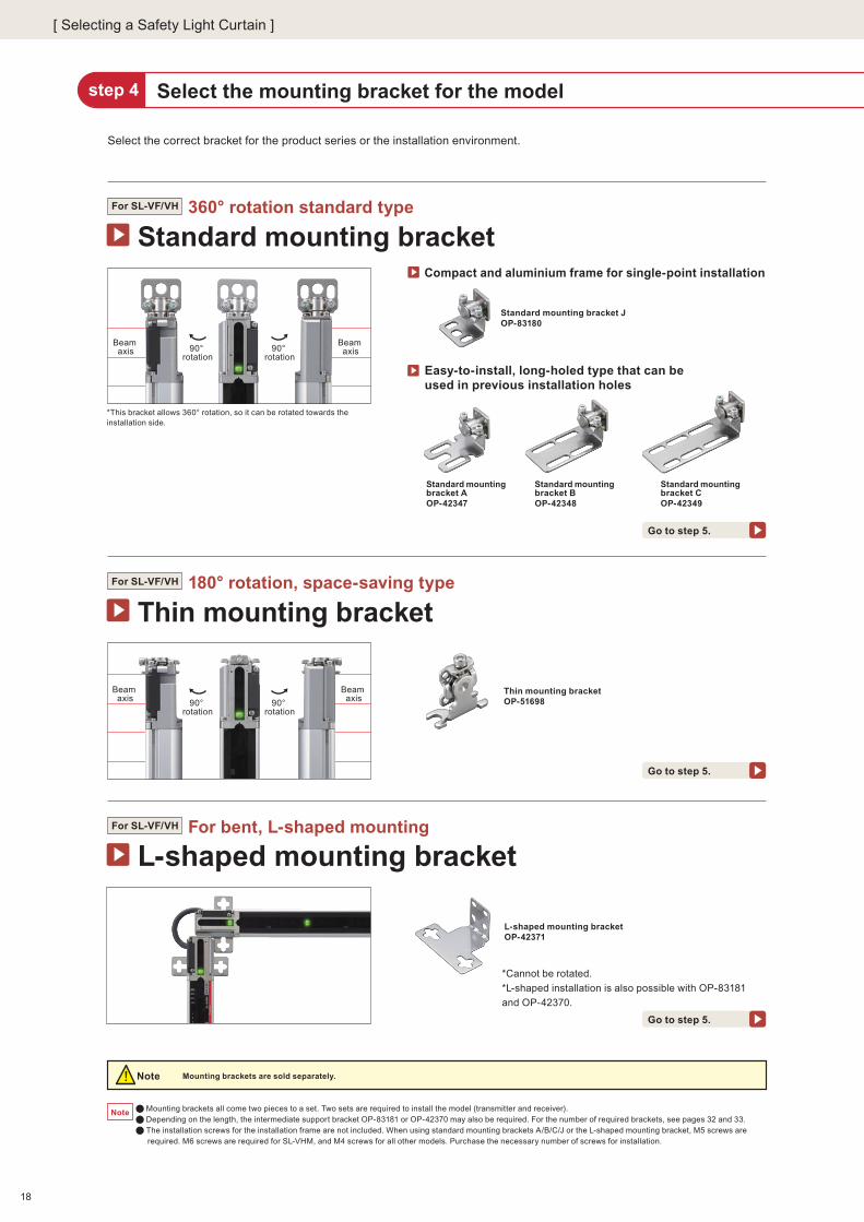
Standard mounting bracket JOP-83180
Thin mounting bracketOP-51698
90° rotation
90° rotation
Beam axis
Beam axis
Beam axis
Beam axis90°
rotation90°
rotation
Standard mounting bracket360° rotation standard type
Compact and aluminium frame for single-point installation
Go to step 5.
Go to step 5.
Go to step 5.
For SL-VF/VH
Thin mounting bracket180° rotation, space-saving typeFor SL-VF/VH
L-shaped mounting bracketFor bent, L-shaped mountingFor SL-VF/VH
L-shaped mounting bracketOP-42371
Mounting brackets are sold separately.
Mounting brackets all come two pieces to a set. Two sets are required to install the model (transmitter and receiver). Depending on the length, the intermediate support bracket OP-83181 or OP-42370 may also be required. For the number of required brackets, see pages 32 and 33. The installation screws for the installation frame are not included. When using standard mounting brackets A/B/C/J or the L-shaped mounting bracket, M5 screws are required. M6 screws are required for SL-VHM, and M4 screws for all other models. Purchase the necessary number of screws for installation.
Note
Select the mounting bracket for the model
Select the correct bracket for the product series or the installation environment.
step 4
Note
Easy-to-install, long-holed type that can be used in previous installation holes
Standard mounting bracket AOP-42347
Standard mounting bracket BOP-42348
Standard mounting bracket COP-42349
*This bracket allows 360° rotation, so it can be rotated towards the installation side.
*Cannot be rotated.
*L-shaped installation is also possible with OP-83181
and OP-42370.
[ Selecting a Safety Light Curtain ]
18

Mounting brackets for SL-VF/VH (All come 2 pcs. to 1 set) Mounting brackets for SL-VHM (All come 2 pcs. to 1 set)
Compact E-to-E bracketOP-83181
E-to-E bracketOP-42370
Standard mounting bracketOP-84259
Space-saving mounting bracketOP-84260
Beam axis
90° rotation
Beam axis
Beam
ax
is
Beam
ax
is
90° rotation
Read the SL-V Instruction Manual when selecting a product.
5 7 864321step
Go to step 5.
Go to step 5.
Go to step 5.
E-to-E mounting bracketIf mounting brackets cannot be used on the upper or lower side on the light curtainFor SL-VF/VH
Tough standard mounting bracketDedicated standard mounting bracket for the tough, water-proof typeFor SL-VFM/VHM
Tough, space-saving mounting bracket
Rear mounting
Side mounting
Side mounting
45° mounting
45° mounting
NEW
NEW
*The figure shows an example of the installation holes facing the left. They can also be turned to face the right.
*There are five possible mounting patterns that can be achieved by changing the screw position.
*The bracket can be rotated 90° by changing the position of the three screws.*The figure shows an example of the installation holes facing the left. They can also be turned to face the right.
Minimise one side of mounting
Firmly secured at four points.
If the safety light curtain is long, intermediate support brackets or L-shaped brackets can also be used.
If the safety light curtain is long, intermediate support brackets or L-shaped brackets can also be used.
Specialised tough, water-proof type, if mounting brackets cannot be used on the upper or lower side on the light curtain
step
For SL-VFM/VHM
Model
OP-83180
OP-42347
OP-42348
OP-42349
OP-51698
OP-42371
OP-83181
OP-42370
Product name
Standard mounting bracket J
Standard mounting bracket A
Standard mounting bracket B
Standard mounting bracket C
Slim mounting bracket
L-shaped mounting bracket
Compact E-to-E bracket
E-to-E bracket
Product name
Standard mounting bracket
Space-saving mounting bracket
Model
OP-84259
OP-84260
19
NEW
NEW
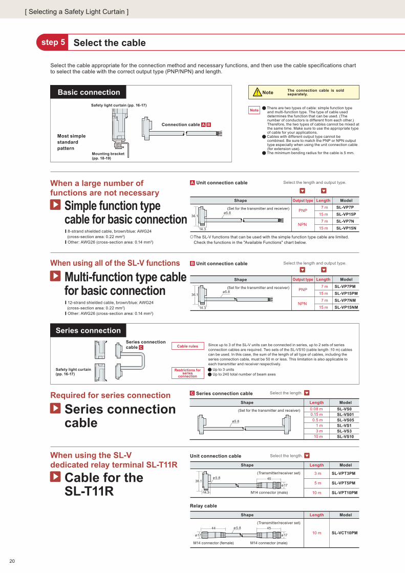
Shape ModelSL-VP7PMSL-VP15PMSL-VP7NMSL-VP15NM
LengthOutput type7 m
15 m
7 m
15 m
PNP
NPN
Shape ModelSL-VP7PSL-VP15PSL-VP7NSL-VP15N
LengthOutput type7 m
15 m
7 m
15 m
PNP
NPN
Shape ModelSL-VS0SL-VS01SL-VS05SL-VS1SL-VS3SL-VS10
Length0.08 m0.15 m0.5 m
1 m3 m
10 m
Shape Model
SL-VPT3PM
SL-VPT5PM
SL-VPT10PM
Length
3 m
5 m
10 m
Shape Model
SL-VCT10PM
Length
10 m
Unit connection cable
(Set for the transmitter and receiver)
Unit connection cable
(Set for the transmitter and receiver)
� There are two types of cable: simple function type and multi-function type. The type of cable used determines the function that can be used. (The number of conductors is different from each other.) Therefore, the two types of cables cannot be mixed at the same time. Make sure to use the appropriate type of cable for your applications.
� Cables with different output type cannot be combined. Be sure to match the PNP or NPN output type especially when using the unit connection cable (for extension use).
� The minimum bending radius for the cable is 5 mm.
Series connection cable
(Set for the transmitter and receiver)
Cable rules Since up to 3 of the SL-V units can be connected in series, up to 2 sets of series connection cables are required. Two sets of the SL-VS10 (cable length :10 m) cables can be used. In this case, the sum of the length of all type of cables, including the series connection cable, must be 50 m or less. This limitation is also applicable to each transmitter and receiver respectively.� Up to 3 units� Up to 240 total number of beam axes
Note
Simple function type cable for basic connection
When a large number of functions are not necessary
Cable for the SL-T11R
When using the SL-V dedicated relay terminal SL-T11R
Multi-function type cable for basic connection
When using all of the SL-V functions
Series connection cable
Required for series connection
Basic connection
Series connection
Select the length and output type.
Select the length and output type.
Select the length.
Select the cablestep 5
ø5.8
(Transmitter/receiver set)
Note
B
ø5.836.1
14.3
36.1ø5.8
14.3
A
C
Select the length.
Mounting bracket (pp. 18-19)
Connection cable ��A B
Safety light curtain (pp. 16-17)
Series connection cable �C
Select the cable appropriate for the connection method and necessary functions, and then use the cable specifications chart to select the cable with the correct output type (PNP/NPN) and length.
The SL-V functions that can be used with the simple function type cable are limited. Check the functions in the "Available Functions" chart below.
Restrictions for series
connection
The connection cable is sold separately.
� 8-strand shielded cable, brown/blue: AWG24 (cross-section area: 0.22 mm2)
� Other: AWG26 (cross-section area: 0.14 mm2)
� 12-strand shielded cable, brown/blue: AWG24 (cross-section area: 0.22 mm2)
� Other: AWG26 (cross-section area: 0.14 mm2)
Unit connection cable
(Transmitter/receiver set)
Relay cable
Most simple standard pattern
Safety light curtain (pp. 16-17)
[ Selecting a Safety Light Curtain ]
20
ø5.8
ø17
4536.1
14.3 M14 connector (male)
ø5.8
ø17
45
ø17
M14 connector (male)M14 connector (female)
44

Shape Model
SL-VPC03PMSL-VPC5PMSL-VPC10PMSL-VPC03NMSL-VPC5NM
LengthOutput type
0.3 m5 m
10 m0.3 m
5 m
PNP
NPN
SL-VCC10PM
SL-VCC10NM
Shape Model
PNP
NPN
10 m
10 m
LengthOutput type
Shape Model
SL-VC5PM
SL-VC10PM
SL-VC5NM
SL-VC10NM
LengthOutput type
5 m
10 m
5 m
10 m
PNP
NPN
Shape Model
SL-VPC03PSL-VPC5PSL-VPC10PSL-VPC03NSL-VPC5N
Output type
PNP
NPN
Shape Model
SL-VCC10P
SL-VCC10N
Output type
PNP
NPN
Shape Model
SL-VC5P
SL-VC10P
SL-VC5N
SL-VC10N
Length
0.3 m5 m
10 m0.3 m
5 m
Length
10 m
10 m
5 m
10 m
5 m
10 m
LengthOutput type
PNP
NPN
Relay cable
Extension cable
(Set for the transmitter and receiver)
(Set for the transmitter and receiver)
(Set for the transmitter and receiver)
M14 connector (male)
M14 connector (male)
M14 connector (female)
M14 connector (female)
Relay cable
Extension cable
(Set for the transmitter and receiver)
(Set for the transmitter and receiver)
(Set for the transmitter and receiver)
M12 connector (male)
M12 connector (male)M12 connector (female)
M12 connector (female)
ø14
47ø5.8
41.5
ø14
ø5.8
Cable rules
44
ø17
5 7 864321step
Simple function type cable for extension
When a large number of functions are not necessary with an extension cable
Multi-function type cable for extension
When using all of the SL-V functions with an extension cable
Extension connection
If optional protection is needed, go to step 6.
If optional protection is not needed, the selection process ends here.
Select the length and output type.
Select the length and output type.
Select the length and output type.
Select the length and output type.
Select the length and output type.
Select the length and output type.
Read the SL-V Instruction Manual when selecting a product.
41.5
ø14
ø5.8
D
E
F
ø14
47
H
I
J
44
ø17 ø17
45
ø17
45ø5.8
Mounting bracket (pp. 18-19)
Safety light curtain (pp. 16-17)
Connection cable (for extension) D H Extension cable F JRelay cable E I
Male connector Female connector Male connector Female connector
When using the connection cable, relay cable and extension cable together, the combined cable length for each the transmitter and receiver must be 30 m or less.
12-strand shielded cable, brown/blue: AWG24 (cross-section area: 0.22 mm2)
Other: AWG26 (cross-section area: 0.14 mm2)
Connection cable (for extension)Use in combination with the relay cable and extension cable.
The SL-V functions that can be used with the simple function type cable are limited.See the "Available Functions" chart on page 31.
8-strand shielded cable, brown/blue: AWG24 (cross-section area: 0.22 mm2)
Other: AWG26 (cross-section area: 0.14 mm2)
Connection cable (for extension)Use in combination with the relay cable and extension cable.
Used when the length of basic connection is not enough
21

This can be used on all models except for SL-VHM. Select the specific protection bar model from the specification chart below according to the SL-V model selected in step 3.
Protection bar mounting dimensions
Note
16.6
49 36
6.5
6.5
6.5
49
6.5
36
16.6
7 25
26.6
25
25
26.6
66.5
61.5 84
69.5
16.6
27
26.6 16.6
4 6.5
14
6.5
6.5
6.5
630 4
26
Simple function type protection barProtect the safety light curtain from shock from the workpieceFor SL-VF/VH
Unit: mm
Unit: mm
B1
B1 B2
B2
The optional protections are sold separately.
Select the protection options as necessarystep 6
Select the model according to the SL-V model selected in step 3.
15° 20°
In case of rear mounting
In case of side mounting
Rear mounted state Side mounted state
� Two sets are required to install the protection bar on both the transmitter and receiver. � When installing the protection bar to SL-V, either the standard bracket A (OP-42347), B (OP-42348), C (OP-42349) or J (OP-83180) is required. � The protection bar and standard mounting brackets are secured with hexagonal-socket bolts, so the angle cannot be adjusted between the mounting brackets and protection bars. However, the angle between the SL-V and mounting brackets can be adjusted in order to adjust the beam axes. � The protection bar can be mounted to the rear or side of the SL-V. Select the appropriate intermediate support bracket according to the type of mounting. � Mount the SL-V within the angle shown to the right in order to prevent the SL-V beam axes from being cut off by the protection bar or intermediate support bracket.
Note
When necessary, add on the protection bar* used to protect the safety light curtain from shock or the front protection cover used to protect the detection surface. *This cannot be used with the tough, water-proof type SL-VFM/VHM.
[ Selecting a Safety Light Curtain ]
Protection bar model
SL-JB15SL-JB23SL-JB31SL-JB39SL-JB47SL-JB55SL-JB63SL-JB71SL-JB79SL-JB87SL-JB95SL-JB103SL-JB111SL-JB119SL-JB127SL-JB143SL-JB159SL-JB175SL-JB191SL-JB207SL-JB223SL-JB239
Not required
340±20380±20420±20460±20500±20540±20580±20620±20460±20510±20570±20620±20500±20540±20580±20
Not required
1530±201650±201770±20
Not required
1550±201670±201790±20
Not required
950±201050±201160±201270±201030±201110±201190±20
Not required
350±20390±20430±20470±20510±20550±20590±20630±20470±20520±20580±20630±20510±20550±20590±20
Not required
940±201040±201150±201260±201020±201100±201180±20
Corresponding SL-V model
1st 2nd 3rd 1st 2nd 3rdSL-V08HSL-V12HSL-V16HSL-V20HSL-V24HSL-V28HSL-V32HSL-V36HSL-V40HSL-V44HSL-V48HSL-V52HSL-V56HSL-V60HSL-V64HSL-V72HSL-V80HSL-V88HSL-V96HSL-V104HSL-V112HSL-V120H
Beam axis pitch: 20 mm
—SL-V23FSL-V31FSL-V39FSL-V47FSL-V55FSL-V63FSL-V71FSL-V79FSL-V87FSL-V95FSL-V103FSL-V111FSL-V119FSL-V127F
—
Beam axis pitch: 10 mm
0
1
2
3
No. of required intermediate
support brackets for the protection
bar
Mounting position for intermediate support brackets for
the protection barin case of side mounting
Mounting position for intermediate support brackets for
the protection barin case of rear mounting
15023031039047055063071079087095010301110119012701430159017501910207022302390
SL-V lengthA
A A A
22
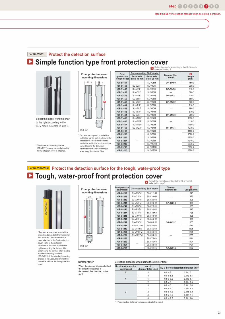
Select the model from the chart to the right according to the SL-V model selected in step 3.
When the dimmer filter is attached, the detection distance is decreased. See the chart to the right.
5 7 864321step
Simple function type front protection coverProtect the detection surfaceFor SL-VF/VH
Tough, water-proof front protection coverProtect the detection surface for the tough, water-proof typeFor SL-VFM/VHM
Unit: mm
Dimmer filter
42.5 52
Unit: mm
*1. The detection distance varies according to the model.
* The L-shaped mounting bracket (OP-42371) cannot be used when the front protection cover is attached.
* Two sets are required to install the protection bar on both the transmitter and receiver. The dimmer filter is used attached to the front protection cover. Refer to the detection distances in the chart on the right when using the dimmer filter.
*Two sets are required to install the protection bar on both the transmitter and receiver. The dimmer filter is used attached to the front protection cover. Refer to the detection distances in the chart to the lower right when using the dimmer filter. When using the dimmer filter, use the standard mounting brackets (OP-84259). If the standard mounting bracket is not used, the dimmer filter may slide off from the front protection cover.
Detection distance when using the dimmer filter
283226
Front protection cover mounting dimensions
Front protection cover mounting dimensions
Select the model according to the SL-V model selected in step 3.
Select the model according to the SL-V model selected in step 3.
Read the SL-V Instruction Manual when selecting a product.
0
1
2
001201234
0.1 to 90.1 to 8.50.1 to 6.50.1 to 50.1 to 80.1 to 60.1 to 4.50.1 to 3.50.1 to 2.5
0.1 to 70.1 to 6.40.1 to 4.70.1 to 3.50.1 to 5.80.1 to 4.30.1 to 3.20.1 to 2.40.1 to 1.8
No. of front protection covers used
No. of dimmer filter used SL-V Series detection distance (m)*1
OP-51454OP-51455OP-51456OP-51457OP-51458OP-51459OP-51460OP-51461OP-51462OP-51463OP-51464OP-51465OP-51466OP-51467OP-51468OP-83198OP-83200OP-83202OP-83204OP-83206OP-83208OP-83210
Corresponding SL-V model
SL-V08HSL-V12HSL-V16HSL-V20HSL-V24HSL-V28HSL-V32HSL-V36HSL-V40HSL-V44HSL-V48HSL-V52HSL-V56HSL-V60HSL-V64HSL-V72HSL-V80HSL-V88HSL-V96HSL-V104HSL-V112HSL-V120H
Beam axis pitch: 20 mm
Beam axis pitch: 10 mm
—SL-V23FSL-V31FSL-V39FSL-V47FSL-V55FSL-V63FSL-V71FSL-V79FSL-V87FSL-V95FSL-V103FSL-V111FSL-V119FSL-V127F
—
150.3230.3310.3390.3470.3550.3630.3710.3790.3870.3950.3
1030.31110.31190.31270.31430.21590.21750.21910.22070.22230.22390.2
Length (mm)
AFront protection
cover model
OP-51469—
OP-51470—
OP-51471—
OP-51472
—
OP-51473
—
OP-51474
—
Dimmer filter model
OP-84238OP-84239OP-84240OP-84241OP-84242OP-84243OP-84244OP-84245OP-84246OP-84247OP-84248OP-84249OP-84250OP-84251OP-84252OP-84253OP-84254OP-84255
Corresponding SL-V model
SL-V12HMSL-V16HMSL-V20HMSL-V24HMSL-V28HMSL-V32HMSL-V36HMSL-V40HMSL-V44HMSL-V48HMSL-V52HMSL-V56HMSL-V60HMSL-V64HMSL-V72HMSL-V80HMSL-V88HMSL-V96HM
SL-V23FMSL-V31FMSL-V39FMSL-V47FMSL-V55FMSL-V63FMSL-V71FMSL-V79FMSL-V87FMSL-V95FMSL-V103FMSL-V111FMSL-V119FMSL-V127FM
—
245325405485565645725805885965
10451125120512851444160417641924
Length (mm)AFront protection
cover model
—
OP-84256
—
OP-84257
—
OP-84258
Dimmer filter model
A
A
23

Select the controllers and power sources if necessary
Select the PC configuration software as necessary
step 7
step 8
Select controllers and power sources for applications where relays and simplified wiring are needed or a controller to allow integration of other safety devices.
SL-T11RSL-U2
Model DescriptionSafety input
Safety light curtainSafety output Other I/O
[ Selecting a Safety Light Curtain ] 5 7 864321step
Type 4 Safety Relay Terminal dedicated for SL-V [SL-T11R]Power source dedicated for a Type 4 light curtain (with class 2 output) [SL-U2]
The following devices help you easily establish a Category 4 compatible safety circuit.
PC configuration softwareThe SL-VH1S Makes It Possible to Reduce The On-Site Installation Time!
Safety Relay Terminal dedicated for the SL-V
SL-T11RSafety Relay Terminal dedicated for SL-V
1 ch(dedicated for SL-V)
1 ch (2 terminals)
EDM input, muting input, AUX output, muting lamp output, etc.
System Model DescriptionInput power supply voltage
Output capacity
Output voltage
Power consumption
Power Source dedicated for Safety Light Curtain
Switching type SL-U2
Power supply dedicated for safety light curtain
100 to 240 VAC±10%(50/60 Hz)
24 VDC ±10%, Class 2
1.8 A 135 VA
Model Name
SL-V1UB
SL-VH1S
SL-V Ver.3 Configuration Software Interface Unit (USB cable included with the SL-V1UB)
SL-V Ver.3 Configuration Software
PC Configuration Software SL-VH1S
USB Cable OP-51580
Interface Unit SL-V1UB
NEW NEW NEW
NEW
(Include with the SL-V1UB)
24
Meaning of Indicators
5
4
3
2
1
OFF
OFF
OFF
OFF
OFF
5
4
3
2
1
OFF
OFF
OFF
OFF
RED
5
4
3
2
1
RED
OFF
OFF
OFF
OFF
5
4
3
2
1
RED
RED
RED
RED
RED
5
4
3
2
1
OFF
OFF
OFF
GREEN
GREEN
5
4
3
2
1
OFF
OFF
OFF
OFF
OFF
5
4
3
2
1
OFF
OFF
GREEN
GREEN
GREEN
5
4
3
2
1
OFF
GREEN
GREEN
GREEN
GREEN
5
4
3
2
1
GREEN
GREEN
GREEN
GREEN
GREEN
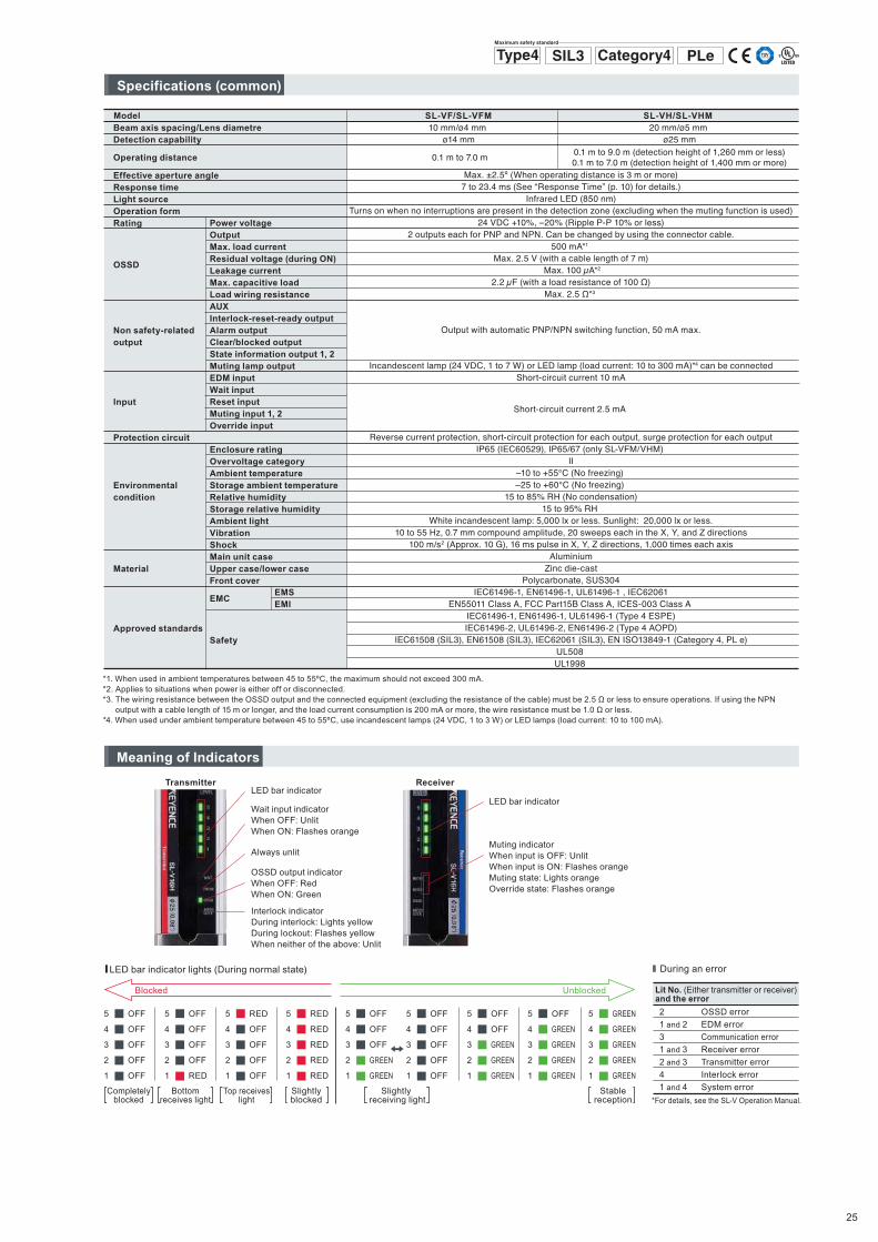
Beam axis spacing/Lens diametre Detection capability
Operating distance
Effective aperture angleResponse timeLight sourceOperation formRating
OSSD
Non safety-related output
Input
Protection circuit
Environmental condition
Material
Approved standards
Model
Max. ±2.5º (When operating distance is 3 m or more)7 to 23.4 ms (See “Response Time” (p. 10) for details.)
Infrared LED (850 nm)Turns on when no interruptions are present in the detection zone (excluding when the muting function is used)
24 VDC +10%, –20% (Ripple P-P 10% or less)2 outputs each for PNP and NPN. Can be changed by using the connector cable.
500 mA*1 Max. 2.5 V (with a cable length of 7 m)
Max. 100 μA*2
2.2 μF (with a load resistance of 100 Ω)Max. 2.5 Ω*3
Output with automatic PNP/NPN switching function, 50 mA max.
Incandescent lamp (24 VDC, 1 to 7 W) or LED lamp (load current: 10 to 300 mA)*4 can be connected
Short-circuit current 10 mA
Short-circuit current 2.5 mA
Reverse current protection, short-circuit protection for each output, surge protection for each outputIP65 (IEC60529), IP65/67 (only SL-VFM/VHM)
II–10 to +55°C (No freezing) –25 to +60°C (No freezing)
15 to 85% RH (No condensation)15 to 95% RH
White incandescent lamp: 5,000 lx or less. Sunlight: 20,000 lx or less.10 to 55 Hz, 0.7 mm compound amplitude, 20 sweeps each in the X, Y, and Z directions
100 m/s2 (Approx. 10 G), 16 ms pulse in X, Y, Z directions, 1,000 times each axisAluminium
Zinc die-castPolycarbonate, SUS304
IEC61496-1, EN61496-1, UL61496-1 , IEC62061EN55011 Class A, FCC Part15B Class A, ICES-003 Class A
IEC61496-1, EN61496-1, UL61496-1 (Type 4 ESPE)IEC61496-2, UL61496-2, EN61496-2 (Type 4 AOPD)
IEC61508 (SIL3), EN61508 (SIL3), IEC62061 (SIL3), EN ISO13849-1 (Category 4, PL e)UL508 UL1998
20 mm/ø5 mm ø25 mm
0.1 m to 9.0 m (detection height of 1,260 mm or less)0.1 m to 7.0 m (detection height of 1,400 mm or more)
SL-VH/SL-VHM 10 mm/ø4 mm
ø14 mm
0.1 m to 7.0 m
SL-VF/SL-VFM
Power voltageOutputMax. load current Residual voltage (during ON) Leakage current Max. capacitive loadLoad wiring resistanceAUX Interlock-reset-ready outputAlarm outputClear/blocked outputState information output 1, 2Muting lamp outputEDM input Wait inputReset inputMuting input 1, 2Override input
Enclosure ratingOvervoltage categoryAmbient temperatureStorage ambient temperatureRelative humidityStorage relative humidityAmbient lightVibrationShockMain unit caseUpper case/lower caseFront cover
EMC
Safety
EMSEMI
*1. When used in ambient temperatures between 45 to 55ºC, the maximum should not exceed 300 mA. *2. Applies to situations when power is either off or disconnected. *3. The wiring resistance between the OSSD output and the connected equipment (excluding the resistance of the cable) must be 2.5 Ω or less to ensure operations. If using the NPN
output with a cable length of 15 m or longer, and the load current consumption is 200 mA or more, the wire resistance must be 1.0 Ω or less. *4. When used under ambient temperature between 45 to 55ºC, use incandescent lamps (24 VDC, 1 to 3 W) or LED lamps (load current: 10 to 100 mA).
PLeType4 SIL3 Category4Maximum safety standard
Specifications (common)
� LED bar indicator lights (During normal state)
Wait input indicatorWhen OFF: UnlitWhen ON: Flashes orange
OSSD output indicatorWhen OFF: RedWhen ON: Green
Interlock indicatorDuring interlock: Lights yellowDuring lockout: Flashes yellowWhen neither of the above: Unlit
Muting indicatorWhen input is OFF: UnlitWhen input is ON: Flashes orangeMuting state: Lights orangeOverride state: Flashes orange
Transmitter ReceiverLED bar indicator
LED bar indicator
Always unlit
Blocked Unblocked
Completelyblocked
Bottomreceives light
Top receiveslight
Slightlyblocked
Slightly receiving light
Stablereception
Lit No. (Either transmitter or receiver) and the error2
1 and 2
3
1 and 3
2 and 3
4
1 and 4
OSSD error
EDM error
Communication error
Receiver error
Transmitter error
Interlock error
System error
III During an error
*For details, see the SL-V Operation Manual.
25

The current consumption of transmitter increase 10 mA and the one of receiver decrease 10 mA if the AUX output (red wire of the transmitter) and the EDM input (red wire of the receiver) are short-circuited and also the following additional condition is met. (The total consumption of both transmitter and receiver is fixed.)� In case where PNP output type cable is used, the condition is that OSSD keeps
OFF state.� In case where NPN output type cable is used, the condition is that OSSD keeps
ON state.
Note
SL-V23F/FMSL-V31F/FMSL-V39F/FMSL-V47F/FMSL-V55F/FMSL-V63F/FMSL-V71F/FMSL-V79F/FMSL-V87F/FMSL-V95F/FMSL-V103F/FMSL-V111F/FMSL-V119F/FMSL-V127F/FM
Unit: mA
Model
8393103112121129136142148154159163166169
Transmitter
When the centre indicator is ON
When the centre indicator is OFF
78808285878992949799101104106109
Receiver809099107115122129135140145149152156158
Transmitter7475777880828385878890929395
Receiver
Response time (OSSD output)
Current consumption
Weight
Note
*If the interruption is present in the detection zone for less than 80 ms, the response time (OFF to ON) is to be 80 ms or more to ensure that the OSSD keeps OFF state for more than 80 ms.
Unit: mA
SL-V08HSL-V12H/HM SL-V16H/HMSL-V20H/HM SL-V24H/HM SL-V28H/HM SL-V32H/HM SL-V36H/HM SL-V40H/HM SL-V44H/HM SL-V48H/HM SL-V52H/HM SL-V56H/HM SL-V60H/HM SL-V64H/HMSL-V72H/HMSL-V80H/HMSL-V88H/HMSL-V96H/HMSL-V104HSL-V112HSL-V120H
Model
5663697581879398103108113117122126130137144149154159162165
Transmitter
When the centre indicator is ON
When the centre indicator is OFF
7072747577798082848587889091939698101104107109112
Receiver525864707681869196100104109112116120126132136140143146147
Transmitter65666768696970717273747475767778808183848687
Receiver
When connecting the SL-V units in series, the response time (ON to OFF) is the sum of the response times of all the individual SL-V units, but the response time (OFF to ON) is the same as that of a single SL-V unit.When connecting the SL-V32H (32 beam axes), SL-V24H (24 beam axes), and SL-V12L (12 beam axes) in series, the response time of each unit is 10.3 ms, 9.2 ms, and 7.6 ms respectively, and the response time (ON to OFF) is 10.3 ms + 9.2 ms + 7.6 ms = 27.1 ms. The response time (OFF to ON) is 27.1 ms + 40 ms = 67.1 ms.
SL-V23F/FMSL-V31F/FMSL-V39F/FMSL-V47F/FMSL-V55F/FMSL-V63F/FMSL-V71F/FMSL-V79F/FMSL-V87F/FMSL-V95F/FMSL-V103F/FMSL-V111F/FMSL-V119F/FMSL-V127F/FM
Response time (OSSD)ON→OFF
9.110.211.312.413.514.615.716.817.919
20.121.222.323.4
Unit: ms
Model OFF→ON*49.150.251.352.453.554.655.756.857.959
60.161.262.363.4
SL-V08HSL-V12H/HM SL-V16H/HMSL-V20H/HM SL-V24H/HM SL-V28H/HM SL-V32H/HM SL-V36H/HM SL-V40H/HM SL-V44H/HM SL-V48H/HM SL-V52H/HM SL-V56H/HM SL-V60H/HM SL-V64H/HMSL-V72H/HMSL-V80H/HMSL-V88H/HMSL-V96H/HMSL-V104HSL-V112HSL-V120H
Response time (OSSD)ON→OFF
77.68.18.79.29.810.310.911.412
12.513.113.614.214.715.816.918
19.120.221.322.4
Unit: ms
Model OFF→ON*47
47.648.148.749.249.850.350.951.452
52.553.153.654.254.755.856.958
59.160.261.362.4
Unit: gWeight
Model SL-V12HM SL-V16HMSL-V20HM SL-V24HM SL-V28HM SL-V32HM SL-V36HM SL-V40HM SL-V44HM SL-V48HM SL-V52HM SL-V56HM SL-V60HM SL-V64HMSL-V72HMSL-V80HMSL-V88HMSL-V96HM
Transmitter670810960111012501400154016901830198021302270242025602850314034403730
Receiver680830970112012701410156017101850200021502290244025902880317034703760
SL-V23FSL-V31F SL-V39FSL-V47F SL-V55F SL-V63F SL-V71F SL-V79F SL-V87F SL-V95F SL-V103F SL-V111F SL-V119F SL-V127F
WeightTransmitter
200270330390450510570620670720760810850890
Receiver205275345405465525585635685735775815855895
Unit: g
Model SL-V23FMSL-V31FM SL-V39FMSL-V47FM SL-V55FM SL-V63FM SL-V71FM SL-V79FM SL-V87FM SL-V95FM SL-V103FM SL-V111FM SL-V119FM SL-V127FM
WeightTransmitter
67083099011501300146016101760190020502190233024702590
Receiver680840
100011601320147016301770191020602200233024602600
Unit: g
Model
Unit: g
SL-V08HSL-V12HSL-V16HSL-V20HSL-V24HSL-V28HSL-V32HSL-V36HSL-V40HSL-V44HSL-V48HSL-V52HSL-V56HSL-V60HSL-V64HSL-V72HSL-V80HSL-V88HSL-V96HSL-V104HSL-V112HSL-V120H
WeightTransmitter
150200250300350400450500550600650700750800860960106011601260136014601570
Model Receiver155205265315365415465515575625675725775835885985109511951295140515051615
26
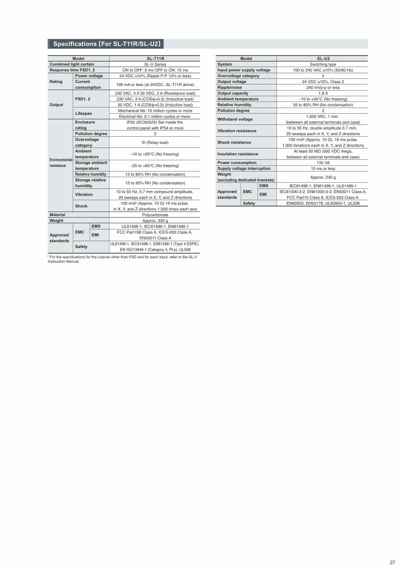
* For the specifications for the outputs other than FSD and for each input, refer to the SL-V Instruction Manual.
Model SL-T11RCombined light curtainResponse time FSD1, 2
Rating
Output
Environmentalresistance
MaterialWeight
Approved standards
SL-V SeriesON to OFF: 6 ms OFF to ON: 15 ms
24 VDC ±10% (Ripple P-P 10% or less)
100 mA or less (at 24VDC, SL-T11R alone)
230 VAC, 4 A 30 VDC, 2 A (Resistance load)230 VAC, 2 A (COSφ=0.3) (Inductive load)30 VDC, 1 A (COSφ=0.3) (Inductive load)Mechanical life: 10 million cycles or moreElectrical life: 0.1 million cycles or more
IP20 (IEC60529) Set inside the control panel with IP54 or more
2
III (Relay load)
–10 to +55°C (No freezing)
–25 to +65°C (No freezing)
15 to 85% RH (No condensation)
15 to 95% RH (No condensation)
10 to 55 Hz, 0.7 mm compound amplitude, 20 sweeps each in X, Y, and Z directions100 m/s² (Approx. 10 G) 16 ms pulse,
in X, Y, and Z directions 1,000 times each axisPolycarbonateApprox. 330 g
UL61496-1, IEC61496-1, EN61496-1FCC Part15B Class A, ICES-003 Class A,
EN55011 Class AUL61496-1, IEC61496-1, EN61496-1 (Type 4 ESPE),
EN ISO13849-1 (Category 4, PLe), UL508
Power voltageCurrent consumption FSD1, 2
Lifespan
Enclosure ratingPollution degreeOvervoltage categoryAmbient temperatureStorage ambient temperatureRelative humidityStorage relative humidity
Vibration
Shock
EMC
Safety
EMS
EMI
Model SL-U2SystemInput power supply voltageOvervoltage categoryOutput voltageRipple/noiseOutput capacityAmbient temperatureRelative humidityPollution degree
Withstand voltage
Vibration resistance
Shock resistance
Insulation resistance
Power consumptionSupply voltage interruptionWeight (excluding dedicated brackets)
Approved standards
Switching type100 to 240 VAC ±10% (50/60 Hz)
ll24 VDC ±10%, Class 2
240 mVp-p or less1.8 A
–10 to +55°C (No freezing)35 to 85% RH (No condensation)
21,500 VAC, 1 min.
(between all external terminals and case)10 to 55 Hz, double amplitude 0.7 mm, 20 sweeps each in X, Y, and Z directions100 m/s² (Approx. 10 G), 16 ms pulse,
1,000 iterations each in X, Y, and Z directionsAt least 50 MΩ (500 VDC mega,
between all external terminals and case)135 VA
10 ms or less
Approx. 240 g
IEC61496-1, EN61496-1, UL61496-1IEC61000-3-2, EN61000-3-2, EN55011 Class A,
FCC Part15 Class A, ICES-003 Class A EN60950, EN50178, UL60950-1, UL508
EMS
EMIEMC
Safety
Specifications [For SL-T11R/SL-U2]
27
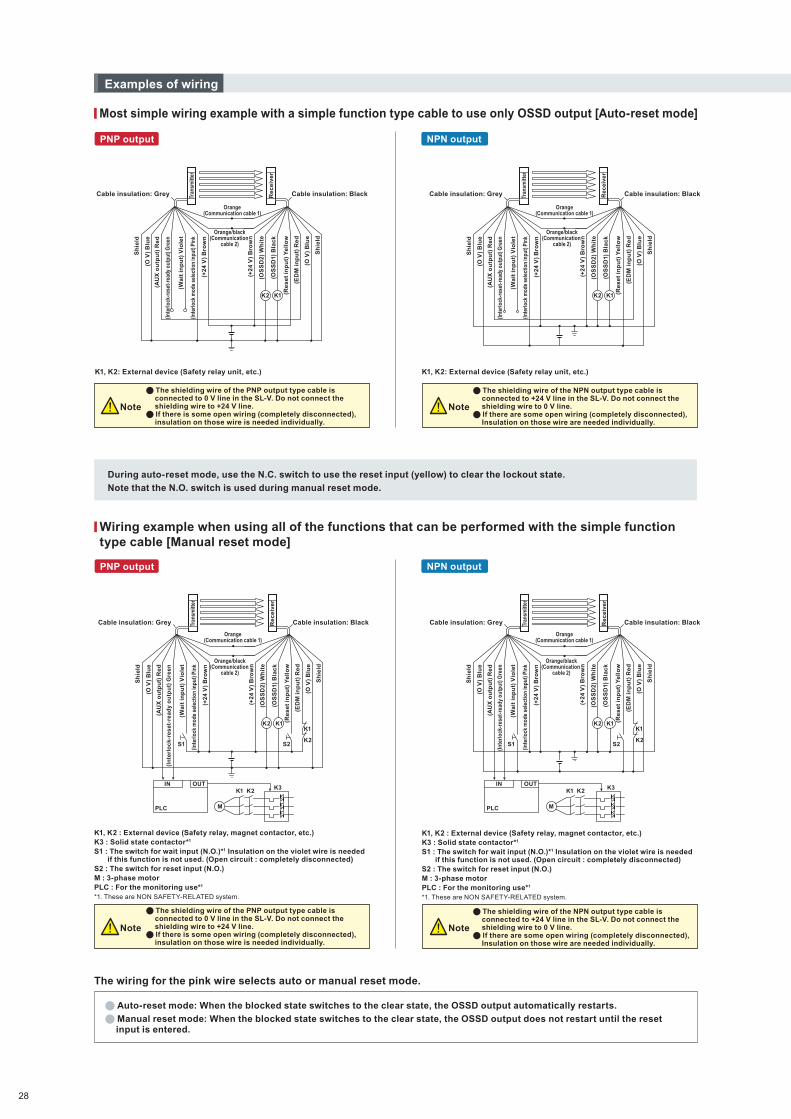
Most simple wiring example with a simple function type cable to use only OSSD output [Auto-reset mode]
K1, K2: External device (Safety relay unit, etc.) K1, K2: External device (Safety relay unit, etc.)
During auto-reset mode, use the N.C. switch to use the reset input (yellow) to clear the lockout state.
Note that the N.O. switch is used during manual reset mode.
The wiring for the pink wire selects auto or manual reset mode.
Examples of wiring
PNP output NPN output
PNP output NPN output
Note
Cable insulation: BlackCable insulation: Grey
Orange(Communication cable 1)
Orange/black(Communication
cable 2)
(Inte
rlock
-res
et-r
eady
out
put)
Gre
en
(Re
se
t in
pu
t) Y
ell
ow
(Wa
it i
np
ut)
Vio
let
(+2
4 V
) B
row
n
Sh
ield
(+2
4 V
) B
row
n
(OS
SD
2)
Wh
ite
(OS
SD
1) B
lac
k
(O V
) B
lue
(AU
X o
utp
ut)
Re
d
(O V
) B
lue
(ED
M i
np
ut)
Re
d
Tran
smitt
er
Re
ce
ive
r
Tran
smitt
er
Rec
eive
r
Tran
smitt
er
Re
ce
ive
r
Tran
smitt
er
Re
ce
ive
r
Sh
ield
(Inte
rlock
mod
e se
lect
ion
inpu
t) Pi
nk
K2 K1
Orange(Communication cable 1)
Orange/black(Communication
cable 2)
Cable insulation: BlackCable insulation: Grey
(In
terl
ock
-res
et-r
ead
y o
utp
ut)
Gre
en
(Re
se
t in
pu
t) Y
ell
ow
(Wa
it i
np
ut)
Vio
let
(+2
4 V
) B
row
n
Sh
ield
(+2
4 V
) B
row
n
(OS
SD
2)
Wh
ite
(OS
SD
1) B
lac
k
(O V
) B
lue
(O V
) B
lue
(ED
M i
np
ut)
Re
d
(AU
X o
utp
ut)
Re
d
Sh
ield
(Inte
rloc
k m
ode
sele
ctio
n in
put)
Pink
K2 K1K1
S2S1K2
IN
PLC
OUT
M
K1 K2 K3
Cable insulation: BlackCable insulation: Grey
Orange(Communication cable 1)
Orange/black(Communication
cable 2)
(Re
se
t in
pu
t) Y
ell
ow
(+2
4 V
) B
row
n
(OS
SD
2)
Wh
ite
(OS
SD
1) B
lac
k
(O V
) B
lue
(ED
M i
np
ut)
Re
d
Sh
ield
(Inte
rlock
-res
et-r
eady
out
put)
Gre
en
(Wa
it i
np
ut)
Vio
let
(+2
4 V
) B
row
n
Sh
ield
(O V
) B
lue
(AU
X o
utp
ut)
Re
d
(Inte
rlock
mod
e se
lect
ion
inpu
t) Pi
nk
K2 K1
Orange(Communication cable 1)
Orange/black(Communication
cable 2)
Cable insulation: BlackCable insulation: Grey
(Inte
rloc
k-re
set-
read
y ou
tput
) Gre
en
(Re
se
t in
pu
t) Y
ell
ow
(Wa
it i
np
ut)
Vio
let
(+2
4 V
) B
row
n
Sh
ield
(+2
4 V
) B
row
n
(OS
SD
2)
Wh
ite
(OS
SD
1) B
lac
k
(O V
) B
lue
(O V
) B
lue
(ED
M i
np
ut)
Re
d
(AU
X o
utp
ut)
Re
d
Sh
ield
(Inte
rloc
k m
ode
sele
ctio
n in
put)
Pink
K2 K1
S2S1
K1
K2
IN
PLC
OUT
M
K1 K2 K3
Note
Note Note
The shielding wire of the PNP output type cable is connected to 0 V line in the SL-V. Do not connect the shielding wire to +24 V line. If there is some open wiring (completely disconnected), insulation on those wire is needed individually.
The shielding wire of the NPN output type cable is connected to +24 V line in the SL-V. Do not connect the shielding wire to 0 V line. If there are some open wiring (completely disconnected), Insulation on those wire are needed individually.
K1, K2 : External device (Safety relay, magnet contactor, etc.)K3 : Solid state contactor*1
S1 : The switch for wait input (N.O.)*1 Insulation on the violet wire is needed if this function is not used. (Open circuit : completely disconnected)
S2 : The switch for reset input (N.O.)M : 3-phase motorPLC : For the monitoring use*1
*1. These are NON SAFETY-RELATED system.
Wiring example when using all of the functions that can be performed with the simple function type cable [Manual reset mode]
Auto-reset mode: When the blocked state switches to the clear state, the OSSD output automatically restarts.
Manual reset mode: When the blocked state switches to the clear state, the OSSD output does not restart until the reset input is entered.
28

Example of wiring for the multi-function type cable
Brown
Brown
Blue
Blue
Black
Black
Cable insulation: BlackCable insulation: Grey
Orange(Communication cable 1)
Orange/black(Communication
cable 2)
Sh
ield
(O V
) B
lue
(Re
se
t in
pu
t) Y
ell
ow
(+2
4 V
) B
row
n
(OS
SD
2)
Wh
ite
(OS
SD
1) B
lac
k
(ED
M i
np
ut)
Re
d
(O V
) B
lue
Sh
ield
(In
terl
oc
k-re
se
t-re
ad
y o
utp
ut)
Gre
en
(Wa
it i
np
ut)
Vio
let
(+2
4 V
) B
row
n
(AU
X o
utp
ut)
Re
d
(Sta
te i
nfo
rma
tio
n o
utp
ut
1) G
rey
(Sta
te i
nfo
rma
tio
n o
utp
ut
2)
Gre
y/b
lac
k
(Ale
rt o
utp
ut)
Pin
k/b
lac
k
(Cle
ar/
Blo
ck
ed
ou
tpu
t) W
hit
e/b
lac
k
(Int
erlo
ck m
ode
sele
ctio
n in
put)
Pin
k
(Mu
tin
g i
np
ut
2)
Lig
ht
blu
e/b
lac
k
(Mu
tin
g i
np
ut
1) L
igh
t b
lue
(Mut
ing
lam
p ou
tput
) Yel
low
/bla
ck
(Ov
err
ide
inp
ut)
Re
d/b
lac
k
K2
S1 S2S3
K1
P1K3K2K1
M
P2
K2K1
IN
PLC
OUTBrown
Brown
Blue
Blue
Black
Black
Orange (Communication wire 1)
Orange/black (Communication
wire 2)
(Sta
te i
nfo
rma
tio
n o
utp
ut
1) G
rey
(Sta
te in
form
atio
n ou
tput
2) G
rey/
blac
k
(Ala
rm o
utp
ut)
Pin
k/b
lac
k
(Cle
ar/b
lock
ed o
utp
ut)
Bla
ck/w
hit
e
(Mu
tin
g i
np
ut
2)
Lig
ht
blu
e/b
lac
k
(Mu
tin
g i
np
ut
1) L
igh
t b
lue
(Mut
ing
lam
p ou
tput
) Yel
low
/bla
ck
(Ov
err
ide
inp
ut)
Re
d/b
lac
k
(Re
se
t in
pu
t) Y
ell
ow
(+2
4 V
) B
row
n
(OS
SD
2)
Wh
ite
(OS
SD
1) B
lac
k
Sh
ield
ed
(O V
) B
lue
(ED
M i
np
ut)
Re
d
(AU
X o
utp
ut)
Re
d
(O V
) B
lue
Sh
ield
ed
(In
terl
ock
-res
et-r
ead
y o
utp
ut)
Gre
en
(Wa
it i
np
ut)
Pu
rple
(+2
4 V
) B
row
n
(In
terl
oc
k s
ele
cti
on
in
pu
t) P
ink
Cable coating: BlackCable coating: Grey
S2S1
K1
K2
S3
M
K1 K2K3
IN
PLC
OUTP1
P2
Overall circuit diagram
Receiver
Transmitter
Interlock mode selection input circuit
Brown
Blue
Pink
Violet
Green
Red
Grey
Grey/blackPink/blackWhite/black
+24 V
0 V
Interlock mode selection input
Wait input
Interlock-reset-ready output
AUX
State information output 1
State information output 2
Alert output
Clear/Blocked output
+24 V
OSSD1
OSSD2
0 V
Reset input
EDM input
Override input
Muting lamp output
Muting input 1
Muting input 2
Wait input circuit
Interlock-reset-ready output circuit
AUX output circuit
State information output 1 circuit
State information output 2 circuit
Clear/Blocked output circuit
Alert output circuit
Black
White
Brown
Blue
Yellow
RedRed/blackYellow/black
Light blue/black
Light blue
Reset input circuit
EDM input circuit
Override input circuit
Muting lamp output circuit
Muting input 1
OSSD PNP output circuit
Output circuit
Muting input 2
Main circuit
Main circuit
Maincircuit
Output
2
7
1
3
4
8
9
10
11
12
PNP
Monitor
Monitor
NPN
PNP
NPN
2
3
1
7
4
8
9
10
11
12
Maincircuit
+24 V
+24 V
Input circuit
InputMain
circuit
+24 V
0 V
0 V
0 V
10Ω
OSSD
OSSD NPN output circuit
Maincircuit
+24 V
0 V
10Ω
OSSD
I/O Circuit Diagram
Tran
smitt
er
Re
ce
ive
r
Ora
ng
eC
om
mu
nic
atio
n c
able
1
Ora
ng
e/b
lack
Co
mm
un
icat
ion
cab
le 2
Ext
erna
l dev
ice
Ext
erna
l dev
ice
Tran
smitt
er
Re
ce
ive
r
NoteNote
L1
5 6
5 6
L1
PNP output NPN output
The shielding wire of the PNP output type cable is connected to 0 V line in the SL-V. Do not connect the shielding wire to +24 V line.
The shielding wire of the NPN output type cable is connected to +24 V line in the SL-V. Do not connect the shielding wire to 0 V line.
K1, K2: External device (Safety relay unit, magnet contactor, etc.)K3: Solid state contactor*1
S1: The switch for wait input (N.O.)*1 Insulation on the violet wire is needed if this function is not used. (Open circuit : completely disconnected)
S2: The switch for reset input (N.O.)S3: The switch for override input (N.O.)L1: Muting lamp (Incandescent lamp or LED lamp)P1, P2: Muting device (PZ self-contained photoelectric sensors <PNP output>, etc.)M: 3-phase motorPLC: For the monitoring use*1
*1. These are NON SAFETY-RELATED system.
K1, K2 : External device (Safety relay unit, magnet contactor, etc.)K3 : Solid state contactor*1S1 : The switch for wait input (N.O.)*1 Insulation on the violet wire is needed if this
function is not used. (Open circuit : completely disconnected)S2 : The switch for reset input (N.O.)S3 : The switch for override input (N.O.)L1 : Muting lamp (Incandescent lamp or LED lamp)P1, P2 : Muting device (PZ self-contained photoelectric sensors <NPN output>, etc.)M : 3-phase motorPLC : For the monitoring use*1
*1. These are NON SAFETY-RELATED system.
29

*For the internal circuit of the SL-V, refer to the SL-V Instruction Manual.
K3, K4 : External device (Magnet contactor, etc.)S1 : The switch for reset input (N.O.)S2 : The switch for wait input (N.C.)S3 : The switch for override input (N.O.)L1 : Muting lamp (Incandescent lamp or LED lamp)P1, P2 : Muting device (PZ self-contained photoelectric sensors <PNP output>, etc.)M : 3-phase motorPLC : For the monitoring use. This is a NON SAFETY-RELATED system.
S2 and PLC are NON SAFETY-RELATED systems.
Examples of wiring [For SL-T11R]
Connector cable for receiver
K2
K1
K1
K2
K3
K3 K4
K3 K4
S1
S2
S3
M
K4
L1
PLC
IN
P1
Brown
BrownBlack
Black
BlueBlue
P2
Internal Circuit Diagram [For SL-T11R]
Pin No.123456789101112
Name
Name
OSSD20 VOSSD1Reset inputCommunication cable 1 (RS485+)Communication cable 2 (RS485-)+24 VEDM inputOverride inputMuting lamp outputMuting input 1Muting input 2
Connector cable for transmitterPin No.
123456789101112
Interlock mode selection input0 VWait inputInterlock-reset-ready outputCommunication cable 1 (RS485+)Communication cable 2 (RS485-)+24 VAUX (auxiliary) outputState information output 1State information output 2Alert outputClear/blocked output
Relay output terminal
Signal input/output terminal
Output connector A
Terminal No.123456789
FSD1
FSD2
Function ground0V+24 V
EDM input
Name
Terminal No.1011121314151617181921
Reset input
+24 VAUX (auxiliary) outputMuting lamp outputClear/blocked outputMuting input 1Muting input 2Wait inputOverride input0 V
Interlock-reset-ready outputAlert output0 V
Name
Pin No.A-1A-2A-3
Name
Output connector B
AUX (auxiliary) outputState information output 1State information output 2
Pin No.B-1B-2B-3
Name
Relay output terminal
Signal input/output terminal (In manual reset mode)
Output connector A
Output connector B
EDM input*3
+24 V
AUX (auxiliary) output*4
Muting lamp output
Clear/blocked output
Muting input 1
Muting input 2
Wait input
Override input
0 V
Name
Name
Terminal No.
1
2
3
4
5
6
7
8
9
Terminal No.
10
11
12
13
14
15
16
17
18
19
21
Name Pin No.
A-1
A-2
A-3
Name Pin No.
B-1
B-2
B-3
Interlock-reset-ready output
Alert output
0 V
AUX (auxiliary) output*4
State information output 1
State information output 1
*5
FSD1
FSD2
FG
0 V*1
+24 V*1
EDM input*2
No. 6 and No. 7 do not need to be wired when the SL-U2 is connected.If it is not necessary to perform error detection for K3 and K4 (when EDM input is not used), keepthe short bar between No. 8 and No. 9 connected.In the auto reset mode, keep the short bar between No. 10 and No. 11 connected. To release thelockout condition of the SL-V through the reset input, connect the N.C. switch.The AUX output operates in the same way for both the signal input/output terminal and the outputconnector B.For screw terminal 14 on the signal input/output terminal, the max load is 80mA. Because of this, amuting lamp must be connected to another power source if the rated power consumption is greaterthan 2W.
*1.
*2.
*3.
*4.
*5.
30
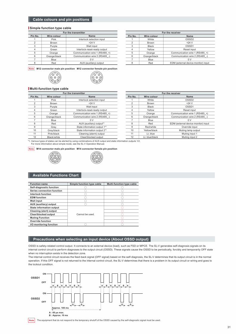
Function name
Self-diagnostic function
Series connection function
Interlock function
EDM function
Wait input
AUX (auxiliary) output
State information output
Cleaning (alert) output
Clear/blocked output
Muting Function
Override function
I/O monitoring function
Multi-function type cableSimple function type cable
Cannot be used.
Available Functions Chart
The equipment that do not respond to the temporary shutoff of the OSSD caused by the self-diagnostic signal must be used.
OSSD1
ON
OFF
A
Approx. 100 ms
A : 60 μs max.B : Approx. 10 ms
A A
A A A A
B B B A A A AB B B A
ON
OFF
OSSD2
Note
Precautions when selecting an input device (About OSSD output)
OSSD is safety-related control output. It connects to an external device (load), such as FSD or MPCE. The SL-V generates self-diagnosis signals on its
internal control circuit to perform diagnoses to the output circuit (OSSD). These signals cause the OSSD to be periodically, forcibly and temporarily OFF state
when no interruption exists in the detection zone.
The internal control circuit receives the feed-back signal (OFF signal) based on the self-diagnosis, the SL-V determines that its output circuit is in the normal
operation. If this OFF signal is not returned to the internal control circuit, the SL-V determines that there is a problem in its output circuit or wiring and goes to
the lockout condition.
Simple function type cableFor the transmitter
Pin No.1
2
3
4
5
6
7
8
Pink
Brown
Purple
Green
Orange
Orange/black
Blue
Red
Interlock selection input
+24 V
Wait input
Interlock-reset-ready output
Communication wire 1 (RS485_+)
Communication wire 2 (RS485_-)
0 V
AUX (auxiliary) output
Wire colour Name
For the receiver
Pin No.1
2
3
4
5
6
7
8
White
Brown
Black
Yellow
Orange
Orange/black
Blue
Red
OSSD2
+24 V
OSSD1
Reset input
Communication wire 1 (RS485_+)
Communication wire 2 (RS485_-)
0 V
EDM (external device monitor) input
Wire colour Name
M12 connector male pin position M12 connector female pin position
Multi-function type cableFor the transmitter
Pin No.1
2
3
4
5
6
7
8
9
10
11
12
Pink
Brown
Purple
Green
Orange
Orange/black
Blue
Red
Grey
Grey/black
Pink/black
Black/white
Interlock selection input
+24 V
Wait input
Interlock-reset-ready output
Communication wire 1 (RS485_+)
Communication wire 2 (RS485_-)
0 V
AUX (auxiliary) output*1
State information output 1*1
State information output 2*1
Cleaning (alarm) output
Clear/blocked output
Wire colour Name
For the receiver
Pin No.1
2
3
4
5
6
7
8
9
10
11
12
White
Brown
Black
Yellow
Orange
Orange/black
Blue
Red
Red/white
Yellow/black
Lt. blue
Lt. blue/black
OSSD2
+24 V
OSSD1
Reset input
Communication wire 1 (RS485_+)
Communication wire 2 (RS485_-)
0 V
EDM (external device monitor) input
Override input
Muting lamp output
Muting input 1
Muting input 2
Wire colour Name
*1. Various types of states can be alerted by using combinations of AUX output and state information outputs 1/2.For more information about simple mode, see the SL-V Operation Manual.
M14 connector male pin position M14 connector female pin position
12
3
45
6
78
1 2
3
45
6
7 8
110
11 12
234
5 6 78
91
101112
234
5678
9
Note
Note
Cable colours and pin positions
31

SL-VF/VHMain unit
Note
If the length for a single SL-V unit is 710 mm or greater, use a compact E-to-E mounting bracket or an E-to-E mounting bracket additionally as an intermediate support bracket. The figures show an example for the use of one compact E-to-E bracket.
Transmitter Receiver
Dimensions for units D – F
Dimensions [For SL-VF/VH]
D
20
10
E
5
5
F
22.5
12
Series
SL-VH
SL-VF
Min. length230 mm
127 beam axes
Max. length1270 mm
120 beam axes
Min. length150 mm
Length
230 mm to 1270 mm
SL-VF unit variation SL-VH unit variation
Max. length2390 mm
Length
150 mm to 2390 mm
SL-VF SL-VH
3.9
12
E
A B C
G
D
5
F
14
9
28
4
28
M3 x 6, Depth: 4.5
ø5.8 cable
A
G
CB
12
3.9
D
59
28
144
EF
28
M3 x 6, Depth: 4.5
23 beam axes 8 beam axes
32
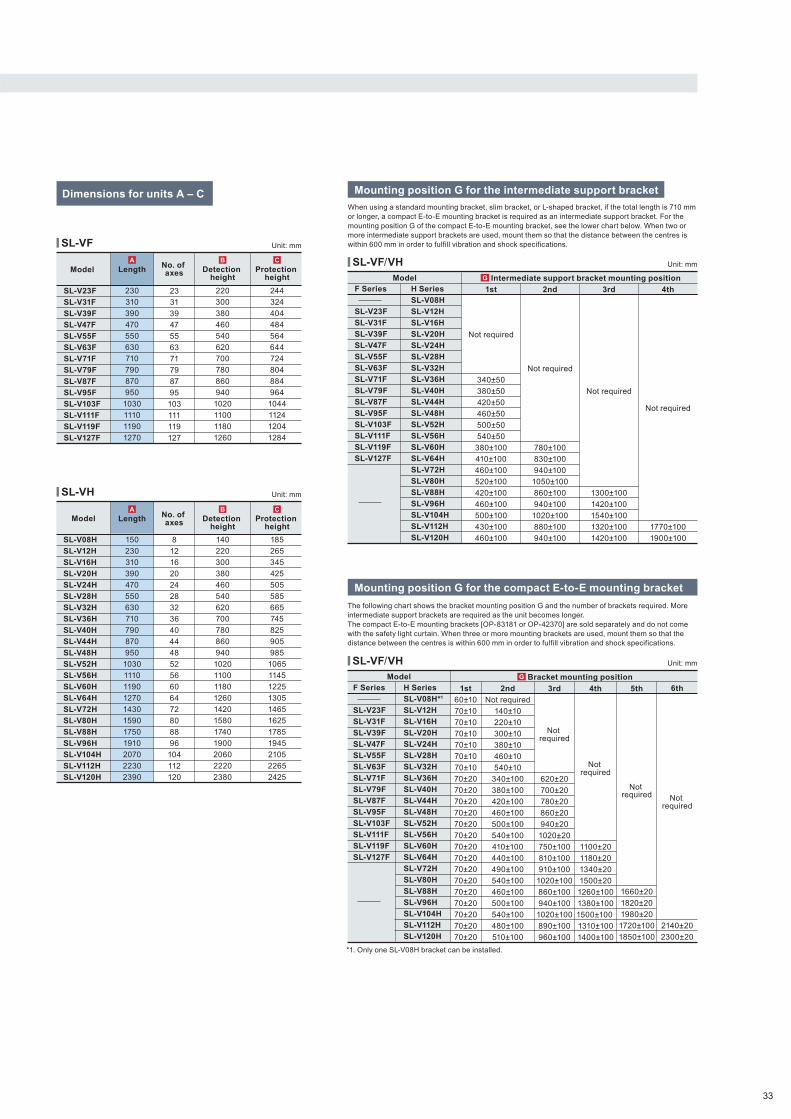
SL-VH
Mounting position G for the intermediate support bracket
SL-VF
Dimensions for units A – CWhen using a standard mounting bracket, slim bracket, or L-shaped bracket, if the total length is 710 mm or longer, a compact E-to-E mounting bracket is required as an intermediate support bracket. For the mounting position G of the compact E-to-E mounting bracket, see the lower chart below. When two or more intermediate support brackets are used, mount them so that the distance between the centres is within 600 mm in order to fulfill vibration and shock specifications.
Mounting position G for the compact E-to-E mounting bracket
The following chart shows the bracket mounting position G and the number of brackets required. More intermediate support brackets are required as the unit becomes longer.The compact E-to-E mounting brackets [OP-83181 or OP-42370] are sold separately and do not come with the safety light curtain. When three or more mounting brackets are used, mount them so that the distance between the centres is within 600 mm in order to fulfill vibration and shock specifications.
SL-VF/VH
*1. Only one SL-V08H bracket can be installed.
SL-VF/VH
Unit: mm
Unit: mm
Model
SL-V08H
SL-V12H
SL-V16H
SL-V20H
SL-V24H
SL-V28H
SL-V32H
SL-V36H
SL-V40H
SL-V44H
SL-V48H
SL-V52H
SL-V56H
SL-V60H
SL-V64H
SL-V72H
SL-V80H
SL-V88H
SL-V96H
SL-V104H
SL-V112H
SL-V120H
No. of axes
8
12
16
20
24
28
32
36
40
44
48
52
56
60
64
72
80
88
96
104
112
120
SL-V23F
SL-V31F
SL-V39F
SL-V47F
SL-V55F
SL-V63F
SL-V71F
SL-V79F
SL-V87F
SL-V95F
SL-V103F
SL-V111F
SL-V119F
SL-V127F
Model
23
31
39
47
55
63
71
79
87
95
103
111
119
127
No. of axes
1st
60±10
70±10
70±10
70±10
70±10
70±10
70±10
70±20
70±20
70±20
70±20
70±20
70±20
70±20
70±20
70±20
70±20
70±20
70±20
70±20
70±20
70±20
2nd
Not required
140±10
220±10
300±10
380±10
460±10
540±10
340±100
380±100
420±100
460±100
500±100
540±100
410±100
440±100
490±100
540±100
460±100
500±100
540±100
480±100
510±100
3rd
Not required
620±20
700±20
780±20
860±20
940±20
1020±20
750±100
810±100
910±100
1020±100
860±100
940±100
1020±100
890±100
960±100
4th
Not required
1100±20
1180±20
1340±20
1500±20
1260±100
1380±100
1500±100
1310±100
1400±100
5th
Not required
1660±20
1820±20
1980±20
1720±100
1850±100
6th
Not required
2140±20
2300±20
1st
Not required
340±50
380±50
420±50
460±50
500±50
540±50
380±100
410±100
460±100
520±100
420±100
460±100
500±100
430±100
460±100
2nd
Not required
780±100
830±100
940±100
1050±100
860±100
940±100
1020±100
880±100
940±100
3rd
Not required
1300±100
1420±100
1540±100
1320±100
1420±100
4th
Not required
1770±100
1900±100
F Series
SL-V23F
SL-V31F
SL-V39F
SL-V47F
SL-V55F
SL-V63F
SL-V71F
SL-V79F
SL-V87F
SL-V95F
SL-V103F
SL-V111F
SL-V119F
SL-V127F
H Series
SL-V08H
SL-V12H
SL-V16H
SL-V20H
SL-V24H
SL-V28H
SL-V32H
SL-V36H
SL-V40H
SL-V44H
SL-V48H
SL-V52H
SL-V56H
SL-V60H
SL-V64H
SL-V72H
SL-V80H
SL-V88H
SL-V96H
SL-V104H
SL-V112H
SL-V120H
F Series
SL-V23F
SL-V31F
SL-V39F
SL-V47F
SL-V55F
SL-V63F
SL-V71F
SL-V79F
SL-V87F
SL-V95F
SL-V103F
SL-V111F
SL-V119F
SL-V127F
H Series
SL-V08H*1
SL-V12H
SL-V16H
SL-V20H
SL-V24H
SL-V28H
SL-V32H
SL-V36H
SL-V40H
SL-V44H
SL-V48H
SL-V52H
SL-V56H
SL-V60H
SL-V64H
SL-V72H
SL-V80H
SL-V88H
SL-V96H
SL-V104H
SL-V112H
SL-V120H
Model
Model
220
300
380
460
540
620
700
780
860
940
1020
1100
1180
1260
Detection height
B
244
324
404
484
564
644
724
804
884
964
1044
1124
1204
1284
Protection height
C
230
310
390
470
550
630
710
790
870
950
1030
1110
1190
1270
LengthA
150
230
310
390
470
550
630
710
790
870
950
1030
1110
1190
1270
1430
1590
1750
1910
2070
2230
2390
LengthA
140
220
300
380
460
540
620
700
780
860
940
1020
1100
1180
1260
1420
1580
1740
1900
2060
2220
2380
Detection height
B
185
265
345
425
505
585
665
745
825
905
985
1065
1145
1225
1305
1465
1625
1785
1945
2105
2265
2425
Protection height
C
Bracket mounting positionG
Intermediate support bracket mounting positionG
Unit: mm
Unit: mm
33

Standard mounting bracket JOP-83180
Rear mounted state Side mounted state
Rear mounted state Side mounted state
Rear mounted state Side mounted state
Rear mounted state Side mounted state
Rear mounted state Side mounted state
Dimensions [Mounting bracket]
Standard mounting bracket AOP-42347
Standard mounting bracket BOP-42348
Standard mounting bracket COP-42349
7.4
29
(20)
9
19
4.5
5
17.5
SL-V length
6
7
27.5
21
2
29
74.5
(31.5)
19
18
ø8 6
27.5 29619
7
5
4.5
9
(20)
SL-V length
6
2219
29
18
2
27.5
21
8
(46.5)
7.5
27
11.5
12
5
7.4
7.5
(19.5)
9
12
(27)
29
196
17.5
5
(46.5)
SL-V length
29
8
12
7.5
5
22192
27.5
21
(41.3)27
27.522
9 5
29
Beam axis pitch
16.5
SL-V length
2.2
22
55
7.4
17.5
Beam axis pitch(2.2)
16.5
SL-V length
6
29
2
27.5
21
(62.5)
14.5
7.5
19
18
14.5
7.5
2
27.5
21
29
18
17
19
6
887.8
8
13
(20.5)
9 5
27.5
13
19
6
8
7.88
17
8 (82.3)
Beam axis pitch
(20.5)
SL-V length
7.4
59
17.5
(82.3)
196
13
8
7.88
17
8
Beam axis pitch
(20.5)
SL-V length
59
27.5
Beam axis pitch
1929
6
(62.5)
SL-V length
14.5
7.5
7.5
14.5
(18.5)
Beam axis pitch
7.4
9 5
14.5
7.5
29
619
7.5
14.5
17.5
(18.5)
(62.5)
SL-V length
29
19
5
6
12
7.5
(19.5)
9
27.5
(46.5)(27)
SL-V length
Beam axis pitch
34
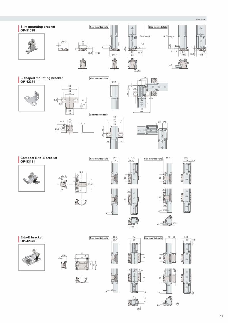
Unit: mm
Rear mounted state Side mounted state
Rear mounted state Side mounted state
Rear mounted state Side mounted state
Rear mounted state
Side mounted state
Slim mounting bracketOP-51698
L-shaped mounting bracketOP-42371
Compact E-to-E bracketOP-83181
E-to-E bracketOP-42370
(6.8)
1.15
(32.4)2228
2
(10.2)
3.9
9
(6.8)
1.1
55
(32.4)22
28
SL-V length
7.4
9
(6.8)1.15
5
(30.9)
22 17.5
31.5
SL-V length
408
2620
2823
5.2
60524430
5.2
60524430
16
26
8
18
20 17.5
14
60
27.5
52
44
25 1659
8
30
2820
1.5(24.5)
28 42
143
(42.7)
5
4
42.3
9
27.526
28
28
3
42.3
4
24.8
34.9
28
28
3
14
7.4
9
17.5
34.83.5
39.728
4
3 363
4
50
528 36
1.5(24)
9
27.525.7
3363
28
124
14
14.9
5
11
28
5028
5
1543363
50
9
7.417.5
28
26 15
28
5
39.7
28 3.5
5
27.5 14 12
R1.8 t=1.0
1612
4
35
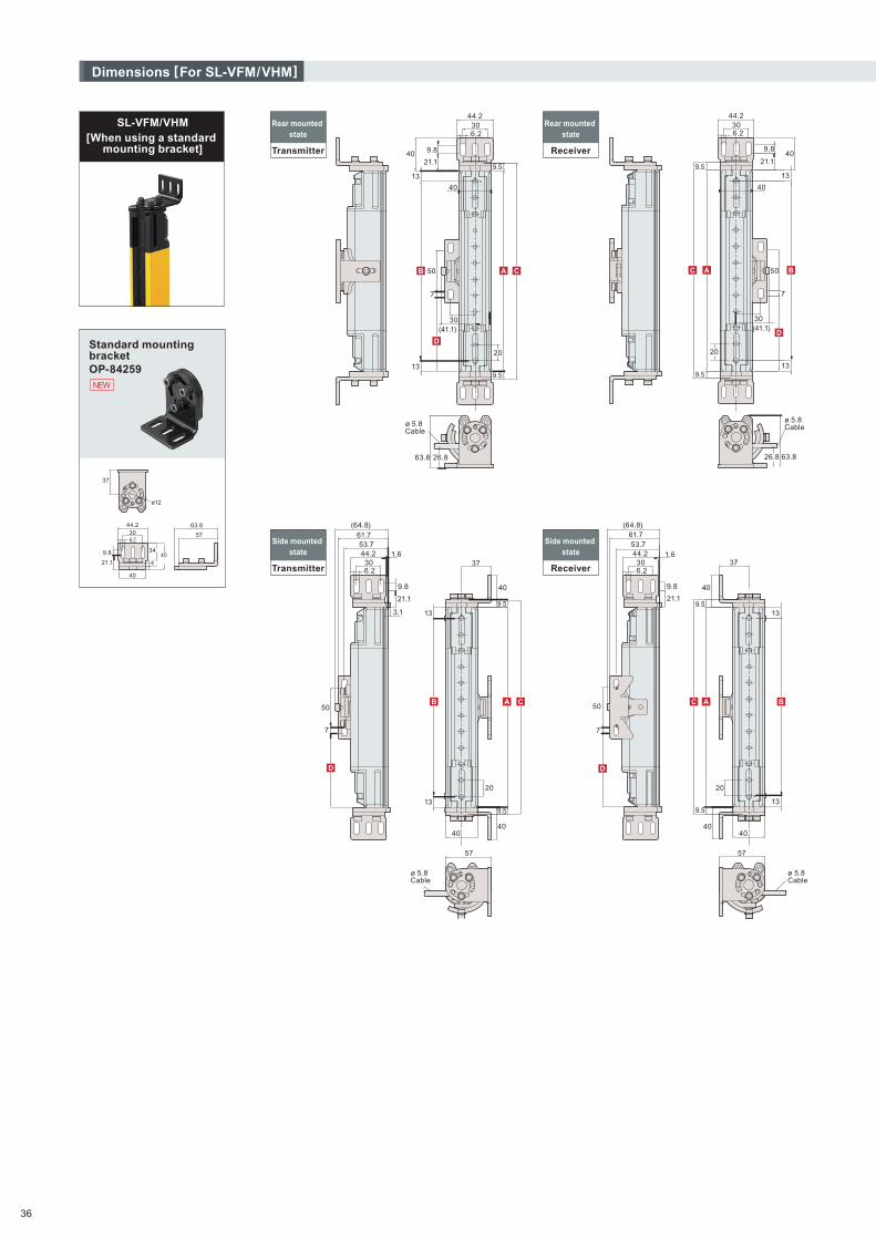
Transmitter
Rear mounted state
Receiver
Rear mounted state
Transmitter
Side mounted state
Receiver
Side mounted state
SL-VFM/VHM[When using a standard
mounting bracket]
Standard mounting bracketOP-84259
57
63.844.230
21.1
9.8 40
40
34
37
6.2
4
ø12
Dimensions [For SL-VFM/VHM]
NEW
36
40
50
30(41.1)
7
13
13
4021.1
44.230
9.5
20
9.5
26.863.8
6.2
9.8
ø 5.8Cable
B
D
A C
6.2
ø 5.8Cable
(41.1)
20
26.8 63.8
13
13
30
50
7
21.140
40
9.8
44.230
9.5
9.5
A B
D
C
(64.8)
57
37
13
53.744.2
61.7
9.8
21.1
3.1 13
40
40
9.5
9.5
301.6
50
7
20
6.2
ø 5.8Cable
40
D
B A C
13
13
40
40
9.5
9.5
20
57
9.8
21.1
7
50
(64.8)
53.744.2
61.7
306.2
ø 5.8Cable
1.637
40
D
A BC

❙ When using a standard mounting bracket [For SL-VFM]
1st
Not required
331±50
371±50
411±50
451±50
317±50
344±50
370±50
397±50
2nd
Not required
666±50
719±50
772±50
826±50
3rd
Not required
SL-V23FM
SL-V31FM
SL-V39FM
SL-V47FM
SL-V55FM
SL-V63FM
SL-V71FM
SL-V79FM
SL-V87FM
SL-V95FM
SL-V103FM
SL-V111FM
SL-V119FM
SL-V127FM
Model
23
31
39
47
55
63
71
79
87
95
103
111
119
127
No. of axes
Unit: mm
246
326
406
486
566
646
726
806
886
966
1046
1126
1206
1286
Length
220
300
380
460
540
620
700
780
860
940
1020
1100
1180
1260
Detection height
244
324
404
484
564
644
724
804
884
964
1044
1124
1204
1284
Protection height
*Space-saving brackets are required as intermediate support brackets as the unit becomes longer.
Space-saving mounting bracket mounting position (for intermediate support)
❙ When using a standard mounting bracket [For SL-VHM]
1st
Not required
331±50
371±50
411±50
451±50
317±50
344±50
370±50
397±50
330±50
370±50
410±50
450±50
2nd
Not required
666±50
719±50
772±50
826±50
691±50
771±50
851±50
931±50
3rd
Not required
1053±50
1173±50
1293±50
1413±50
SL-V12HM
SL-V16HM
SL-V20HM
SL-V24HM
SL-V28HM
SL-V32HM
SL-V36HM
SL-V40HM
SL-V44HM
SL-V48HM
SL-V52HM
SL-V56HM
SL-V60HM
SL-V64HM
SL-V72HM
SL-V80HM
SL-V88HM
SL-V96HM
Model
12
16
20
24
28
32
36
40
44
48
52
56
60
64
72
80
88
96
No. of axes
Unit: mm
246
326
406
486
566
646
726
806
886
966
1046
1126
1206
1286
1446
1606
1766
1926
Length
220
300
380
460
540
620
700
780
860
940
1020
1100
1180
1260
1420
1580
1740
1900
Detection height
265
345
425
505
585
665
745
825
905
985
1065
1145
1225
1305
1465
1625
1785
1945
Protection height
*More space-saving brackets are required as intermediate support brackets as the unit becomes longer.
Space-saving mounting bracket mounting position (for intermediate support)
A B C D
A B C D
37

Transmitter
Rear mounted state
Receiver
Rear mounted state
Transmitter
Side mounted state
Receiver
Side mounted state
SL-VFM/VHM[When using space-saving
mounting brackets]
Space-saving mounting bracketOP-84260
5055
(3.1)54.2
29.28
78
(46)
6.2
7
7
Dimensions [For SL-VFM/VHM]
NEW
38
(41.1)
60.7 54.4
38
40
13
13
13.7
26.8
50
50
50
22.9
6.34.727
9.5
9.5
30
7
7
7
20
6.2D
AB
E
D
C
9.5
9.5
50
40
13
13
50
60.754.426.8
276.3 4.7
22.9
38
50
30
7
7
7
20
6.2
A B
D
D
E
C
ø 5.8 Cable
4 x M5Depth 6.2
50
17
50
53.761.7
(64.8)
50
37
9.5
9.5
274.7 6.3
22.9
40
7
7
7
6.2
D
E
B A C
D
ø 5.8 Cable
4 x M5Depth 6.2
50
50
50
4.76.3
22.9
7
7
7
9.5
9.5
17
37
27
53.761.7
(64.8)
6.2
D
E
AC B
D
ø 5.8 Cable
4 x M5Depth 6.2
ø 5.8 Cable
4 x M5Depth 6.2
(41.1)

❙ When using space-saving mounting brackets [For SL-VFM]
1st
Not required
331±50
371±50
411±50
451±50
317±50
344±50
370±50
397±50
2nd
Not required
666±50
719±50
772±50
826±50
3rd
Not required
SL-V23FM
SL-V31FM
SL-V39FM
SL-V47FM
SL-V55FM
SL-V63FM
SL-V71FM
SL-V79FM
SL-V87FM
SL-V95FM
SL-V103FM
SL-V111FM
SL-V119FM
SL-V127FM
Model
23
31
39
47
55
63
71
79
87
95
103
111
119
127
No. of axes
Unit: mm
246
326
406
486
566
646
726
806
886
966
1046
1126
1206
1286
Length
220
300
380
460
540
620
700
780
860
940
1020
1100
1180
1260
Detection height
244
324
404
484
564
644
724
804
884
964
1044
1124
1204
1284
Protection height
60±20
Mounting position
*Space-saving brackets are required as intermediate support brackets as the unit becomes longer.
Mounting position (for intermediate support)
❙ When using space-saving mounting brackets [For SL-VHM]
1st
Not required
331±50
371±50
411±50
451±50
317±50
344±50
370±50
397±50
330±50
370±50
410±50
450±50
2nd
Not required
666±50
719±50
772±50
826±50
691±50
771±50
851±50
931±50
3rd
Not required
1053±50
1173±50
1293±50
1413±50
SL-V12HM
SL-V16HM
SL-V20HM
SL-V24HM
SL-V28HM
SL-V32HM
SL-V36HM
SL-V40HM
SL-V44HM
SL-V48HM
SL-V52HM
SL-V56HM
SL-V60HM
SL-V64HM
SL-V72HM
SL-V80HM
SL-V88HM
SL-V96HM
Model
12
16
20
24
28
32
36
40
44
48
52
56
60
64
72
80
88
96
No. of axes
Unit: mm
246
326
406
486
566
646
726
806
886
966
1046
1126
1206
1286
1446
1606
1766
1926
Length
220
300
380
460
540
620
700
780
860
940
1020
1100
1180
1260
1420
1580
1740
1900
Detection height
265
345
425
505
585
665
745
825
905
985
1065
1145
1225
1305
1465
1625
1785
1945
Protection height
60±20
Mounting position
*More space-saving brackets are required as intermediate support brackets as the unit becomes longer.
Mounting position (for intermediate support)
A B C D
A B C ED
39
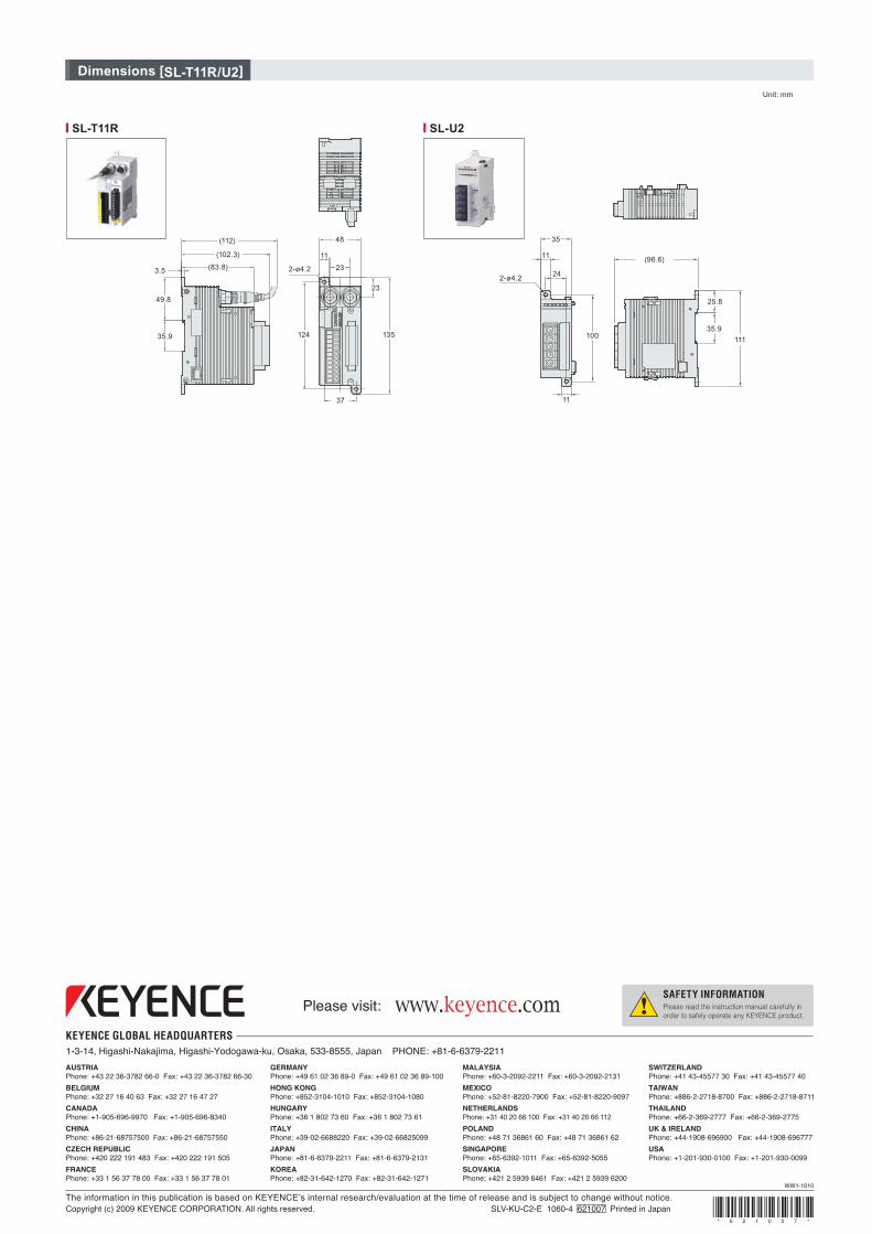
Dimensions [SL-T11R/U2]
❙ SL-T11R ❙ SL-U2
(112) 48
11
23
23
37
135
(96.6)
35
100
11
24
11
2-ø4.22-ø4.2
11135.9
25.8
124
(83.8)3.5
49.8
35.9
(102.3)
Unit: mm
WW1-1010
www.keyence.com SAFETY INFORMATIONPlease read the instruction manual carefully in order to safely operate any KEYENCE product.
Please visit:
SINGAPOREPhone: +65-6392-1011 Fax: +65-6392-5055
SLOVAKIAPhone: +421 2 5939 6461 Fax: +421 2 5939 6200
MEXICOPhone: +52-81-8220-7900 Fax: +52-81-8220-9097
NETHERLANDSPhone: +31 40 20 66 100 Fax: +31 40 20 66 112
POLANDPhone: +48 71 36861 60 Fax: +48 71 36861 62
MALAYSIAPhone: +60-3-2092-2211 Fax: +60-3-2092-2131
CZECH REPUBLICPhone: +420 222 191 483 Fax: +420 222 191 505
AUSTRIAPhone: +43 22 36-3782 66-0 Fax: +43 22 36-3782 66-30
BELGIUMPhone: +32 27 16 40 63 Fax: +32 27 16 47 27
CHINAPhone: +86-21-68757500 Fax: +86-21-68757550
CANADAPhone: +1-905-696-9970 Fax: +1-905-696-8340
FRANCEPhone: +33 1 56 37 78 00 Fax: +33 1 56 37 78 01
KOREAPhone: +82-31-642-1270 Fax: +82-31-642-1271
GERMANYPhone: +49 61 02 36 89-0 Fax: +49 61 02 36 89-100
HUNGARYPhone: +36 1 802 73 60 Fax: +36 1 802 73 61
HONG KONGPhone: +852-3104-1010 Fax: +852-3104-1080
ITALYPhone: +39-02-6688220 Fax: +39-02-66825099
JAPANPhone: +81-6-6379-2211 Fax: +81-6-6379-2131
SWITZERLANDPhone: +41 43-45577 30 Fax: +41 43-45577 40
THAILANDPhone: +66-2-369-2777 Fax: +66-2-369-2775
TAIWANPhone: +886-2-2718-8700 Fax: +886-2-2718-8711
UK & IRELANDPhone: +44-1908-696900 Fax: +44-1908-696777
USA Phone: +1-201-930-0100 Fax: +1-201-930-0099
KEYENCE GLOBAL HEADQUARTERS1-3-14, Higashi-Nakajima, Higashi-Yodogawa-ku, Osaka, 533-8555, Japan PHONE: +81-6-6379-2211
Copyright (c) 2009 KEYENCE CORPORATION. All rights reserved. SLV-KU-C2-E 1060-4 621007 Printed in JapanThe information in this publication is based on KEYENCE’s internal research/evaluation at the time of release and is subject to change without notice.
* 6 2 1 0 0 7 *