super radius mill asr - mmc-hitachitool.co.jp · asr type çÑ ô ù å´ µÛç"43 super...
TRANSCRIPT
ASR typeアルファ 高送りラジアスミル ASR形Super Radius Mill ASR type
New Produc t News No.1204-5 2017-10
高送りラジアスミル Super Radius Mill

● 耐摩耗性に優れた超微粒超硬母材と新コーティング「AJコーティング」の採用により耐摩耗性を向上させました。
● 50HRC~の高硬度材の切削加工で耐摩耗性に優れます。・Employs an ultra-fine cemented carbide substrate and the new "AJ Coating" to improve wear resistance.・Excellent wear resistance when machining high hardness materials of 50HRC or higher.
特長 Features
●焼入れ鋼(50~60HRC):SKD11,SKD61,SKH,SUS420系等・Hardened steel (50 to 60 HRC): SKD11, SKD61, SKH, SUS420, etc.
得意分野 Strong fields
高硬度材加工用材種Grade for machining high-hardness materials
PVD Technology JP4105
ワーク Work material:SKD11(61HRC) 使用工具 Tool:ASRS2032-5インサート Insert:EPNW0603TN-8切削条件 Cutting conditions:vc=80m/min fz=0.2mm/t ap×ae=0.5×21mm乾式加工 Dry ※単一刃加工 Single-flute cutting
従来品 JP4105
00 5 10 15
0.2
0.4
0.6
切削距離 Cutting length (m)
Conventional
逃げ
面最
大摩
耗幅
Fl
ank
wea
r VB
max
(mm
)
銅 炭素鋼合金鋼
ステンレス鋼工具鋼
プリハードン鋼焼入れ鋼
30~45HRC
焼入れ鋼45~55HRC
焼入れ鋼55~62HRC
Copper Carbon steelAlloy steel
Stainless steelTool steel
Pre-hardened steelHardened steel
30̃45HRC
Hardened steel45̃55HRC
Hardened steel55̃62HRC
テクノロジーTechnology
特許 Pat. No.第3317490号Applications
加工用途 Roughing
荒
プリハードン鋼・焼入れ鋼加工用材種 Grade for machining pre-hardened or hardened materials
PVD Technology
● 耐摩耗性と靱性のバランスに優れた微粒超硬母材と新コーティング「AJコーティング」の採用により耐摩耗性と耐チッピング性を向上させました。
● 汎用性が高く、30~50HRCの鋼材の切削加工で耐摩耗性と耐チッピング性に優れます。・Employs a fine carbide substrate with an excellent balance between wear resistance and toughness and
the new "AJ Coating" to provide improved wear resistance and chipping resistance.・ Highly versatile with excellent wear resistance and chipping resistance when machining steel materials
with hardnesses of 30 to 50 HRC.
● 30~50HRCのプリハードン鋼・焼入れ鋼の切削加工において優れた切削性能を発揮します。● 難削系のダイカスト金型用鋼や析出硬化系ステンレス鋼、仕上げ加工において
も優れた耐摩耗性を発揮します。・Exhibits excellent cutting performance when machining pre-hardened or hardened steel with hardnesses of 30 to 50 HRC.・ Exhibits excellent wear resistance even on difficult-to-cut diecast tool steel or precipitation-hardened
stainless steel, or for finishing.
特長 Features
得意分野 Strong fields
JP4120
ステンレス鋼系材料加工用材種Grade for machining stainless-steel materials
PVD Technology
● 靱性に優れた超硬母材と新コーティング「AJコーティング」の採用により、ステンレス鋼系材料の切削加工に対して耐摩耗性と耐チッピング性を向上させました。
● 耐溶着性に優れる「AJコーティング」の採用により、ステンレス鋼系材料の加工で発生する被削材の溶着を低減しました。
・Employs a carbide substrate with high toughness and the new "AJ Coating" to improve wear resistance and chipping resistance when machining stainless-steel materials.
・ Employs AJ Coating with excellent welding resistance to reduce the welding to work material that occurs when machining stainless steel materials.
● ステンレス鋼系材料の加工全般において長寿命を実現します。・Provides long tool life for general processing of stainless-steel materials.
特長 Features
得意分野 Strong fields
JM4160切削性能 Cutting performance
切削性能 Cutting performance
切削性能 Cutting performance
ワーク Work material:SUS304使用工具 Tool:ASRS2032R-5インサート Insert:EPMT0603EN-8LF切削条件 Cutting conditions:vc=180m/min fz=0.5mm/t ap×ae=0.8×21mm湿式加工 Wet ※単一刃加工 Single-flute cutting
ワーク Work material:SKD61(40HRC)使用工具 Tool:ASRT5063R-4インサート Insert:WDNW140520切削条件 Cutting conditions:vc=90m/min fz=0.8mm/t ap×ae=1×44mm乾式加工 Dry ※単一刃加工 Single-flute cutting
従来品B
従来品C従来品A JP4120
60504030201000
0.2
0.4
0.6
逃げ
面最
大摩
耗幅
Fl
ank
wea
r VB
max
(mm
)
従来品
JM4160
0 4 8 120
0.2
0.4
0.6
切削距離 Cutting length (m)
Conventional
逃げ
面最
大摩
耗幅
Fl
ank
wea
r VB
max
(mm
)
切削距離 Cutting length (m)
Conventional A
Conventional B
Conventional C
AJ Coating seriesAJコーティングシリーズ皮膜の組織Layer structure
AJコーティング Coating Patent Pending
特許申請中
コーティング膜の膜組織写真Photograph of coating structure
耐溶着性・低抵抗コーティング表層Welding-resistant low-cutting-force coatingsurface layer
耐摩耗性・耐チッピング性に優れたコーティングCoating with excellent wear resistance and chipping resistance
AJコーティングシリーズの特長 Features of AJ Coating series
新技術!! New technology!!
● 従来膜よりもAl含有量を増加した新組成系のAlTi系皮膜を採用。● 耐摩耗性・耐チッピング性および耐熱性に優れる!
● 高Al含有の新コーティング膜は、新組成系の採用と結晶組織の適正化により、耐摩耗性と耐チッピング性を改善!
● 耐溶着性に優れた低摩擦効果のコーティング最表層を採用。被削材の溶着が低減し切削抵抗が低下!
・Employs an AlTi layer with a new composition created by increasing the Al content of conventional layers.・Excellent wear resistance, chipping resistance, and heat resistance!
・The new layer with high Al content employs a new composition and optimizes the crystal structure to improve wear resistance and chipping resistance!
・Employs a low-friction-effect coating with excellent welding resistance as the top-most surface layer. This reduces welding to the work and decreases cutting force!
JP4120 JP4105 JM4160
SCM440(32HRC)の切削試験結果 Wear graph after cutting SCM440(32HRC) P20(32HRC)の切削試験結果 Wear graph after cutting P20(32HRC)
皮膜の組織 Layer structure
鋼一般加工用材種General purpose for steel
PVD Technology
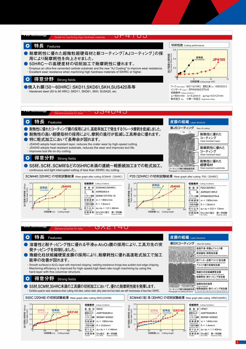
● 耐熱性に優れたコーティング膜の採用により、高能率加工で発生するクレータ摩耗を低減しました。● 耐熱性の高い超硬母材の採用により、摩耗の進行が低減し工具寿命に優れます。● 特に乾式加工において長寿命が図れます。
・JS4045 adopts heat resistant layer, reduces the crater wear by high-speed cutting.・ JS4045 adopts heat resistant substrate, reduces the wear and improves tool life.・ Improves tool life on dry cutting.
● SS材、SC材、SCM材などの35HRC未満の連続~軽断続加工までの乾式加工。・continuous and light interrupted cutting of less than 35HRC dry cutting.
特長 Features
得意分野 Strong fields
JS4045
耐熱性に優れたコーティングHeat resistant layer
耐摩耗性に優れたコーティングWear resistant layer
耐熱性に優れた超硬母材Heat resistant substrate
新JSコーティング New JS coating
コーティング膜の膜組織写真Photograph of coating structure
被 削 材Work Material工 具Toolインサート型番Insert Model切 削 速 度Cutting Speed1刃当りの速度Speed per flute切 り 込 みCutting depth切 削 油 剤Coolant
SCM440(32HRC)
ASR5063-4
EDNW15T4TN-15
vc = 180m/min
fz = 1.5mm/t
ap×ae = 1.0 × 42mm
Dry(Air)加工 単一刃切削
切削条件 Cutting Conditions
Single-tip cuttingDry cutting切削距離 (m) Cutting length
逃げ
面最
大摩
耗幅
VB
max
Flan
k w
ear (
mm
)
0.4
0.3
0.2
0.1
00 50 100 150
JS4045従来品Conventional
切削距離 (m) Cutting length
逃げ
面最
大摩
耗幅
VB
max
Flan
k w
ear (
mm
)
0.4
0.3
0.2
0.1
00 100 200 300
JS4045従来品Conventional 被 削 材
Work Material工 具Toolインサート型番Insert Model切 削 速 度Cutting Speed1刃当りの速度Speed per flute切 り 込 みCutting depth切 削 油 剤Coolant
P20(32HRC)
ASRS2016R-2
EPNW0603TN-8
vc = 180m/min
fz = 1.5mm/t
ap×ae = 0.5 × 13mm
Dry(Air)加工 単一刃切削
切削条件 Cutting Conditions
Single-tip cuttingDry cutting
S50C(220HB)の切削試験結果 Wear graph after cutting S50C(220HB) SCM440(改)系(30HRC)の切削試験結果 Wear graph after cutting HPM7(30HRC)
皮膜の組織 Layer structure
鋼一般加工用材種General purpose for steel
CVD Technology
● 溶着性と耐チッピング性に優れる平滑α-Al2O3膜の採用により、工具刃先の突発チッピングを抑制しました。
● 微細化柱状組織硬質皮膜の採用により、耐摩耗性に優れ高速乾式加工で加工能率の改善が図れます。
・Smooth surfaced α-Al2O3 layer with improved chipping / welding resistance brings less sudden-tool-edge-chipping. ・Machining efficiency is improved for high-speed,high-feed-rate rough machining by using the
hard-layer with fine columnar structure.
● SS材,SCM材,35HRC未満の工具鋼の切削加工において、優れた耐摩耗性能を発揮します。・Exhibits superior wear resistance when cutting mild steel, carbon steel, alloy steel and tool steel use with hardnesses of less than 35HRC.
特長 Features
得意分野 Strong fields
GX2140
表面平滑・厚膜αアルミナ膜Smooth surface and thick layer 耐溶着性・耐熱性改善Improved welding resistance and heat resistance
新アンカー効果アルミナ結合膜New anchor-effect alumina bonding layerアルミナ膜の密着性改善Improved adhesion to aluminium oxide layer
微細化柱状組織硬質皮膜Hard layer with fine columnar structure耐摩耗性・耐チッピング性改善Improved wear resistance and chipping resistance
強靭性母材適用Tough substrate耐熱亀裂性・耐チッピング性改善Improved high toughtness,thermal chipping resistance
新GXコーティング New GX coating
コーティング膜の膜組織写真Photograph of coating structure
被 削 材Work Material使用ホルダーHolder usedインサート型番Insert Model切 削 速 度Cutting Speed1刃当りの速度Speed per flute切 り 込 みCutting depth切 削 油 剤Coolant
S50C
ASRT5063R-4
WDNW140520
vc = 180m/min
fz = 2.0mm/t
ap×ae = 1 × 44mm
Dry加工 単一刃切削
切削条件 Cutting Conditions
Single-tip cuttingDry cutting
被 削 材Work Material使用ホルダーHolder usedインサート型番Insert Model切 削 速 度Cutting Speed1刃当りの速度Speed per flute切 り 込 みCutting depth切 削 油 剤Coolant
HPM7
ASRT5063R-4
WDNW140520
vc = 140m/min
fz = 1.4mm/t
ap×ae = 1 × 43mm
Dry加工 単一刃切削
切削条件 Cutting Conditions
Single-tip cuttingDry cutting切削距離 (m) Cutting length
逃げ
面最
大摩
耗幅
VB
max
Flan
k w
ear (
mm
)
0.5
0.4
0.3
0.2
0.1
00 100 200 300 400
GX2140従来品Conventional
従来品Conventional
切削距離 (m) Cutting length
逃げ
面最
大摩
耗幅
VB
max
Flan
k w
ear (
mm
)
0.5
0.4
0.3
0.2
0.1
00 30 60 90 120
GX2140従来品Conventional
従来品Conventional
GX2140JS4045 JP4120
JM4160 JP4105
2
● 耐摩耗性に優れた超微粒超硬母材と新コーティング「AJコーティング」の採用により耐摩耗性を向上させました。
● 50HRC~の高硬度材の切削加工で耐摩耗性に優れます。・Employs an ultra-fine cemented carbide substrate and the new "AJ Coating" to improve wear resistance.・Excellent wear resistance when machining high hardness materials of 50HRC or higher.
特長 Features
●焼入れ鋼(50~60HRC):SKD11,SKD61,SKH,SUS420系等・Hardened steel (50 to 60 HRC): SKD11, SKD61, SKH, SUS420, etc.
得意分野 Strong fields
高硬度材加工用材種Grade for machining high-hardness materials
PVD Technology JP4105
ワーク Work material:SKD11(61HRC) 使用工具 Tool:ASRS2032-5インサート Insert:EPNW0603TN-8切削条件 Cutting conditions:vc=80m/min fz=0.2mm/t ap×ae=0.5×21mm乾式加工 Dry ※単一刃加工 Single-flute cutting
従来品 JP4105
00 5 10 15
0.2
0.4
0.6
切削距離 Cutting length (m)
Conventional
逃げ
面最
大摩
耗幅
Fl
ank
wea
r VB
max
(mm
)
銅 炭素鋼合金鋼
ステンレス鋼工具鋼
プリハードン鋼焼入れ鋼
30~45HRC
焼入れ鋼45~55HRC
焼入れ鋼55~62HRC
Copper Carbon steelAlloy steel
Stainless steelTool steel
Pre-hardened steelHardened steel
30̃45HRC
Hardened steel45̃55HRC
Hardened steel55̃62HRC
テクノロジーTechnology
特許 Pat. No.第3317490号Applications
加工用途 Roughing
荒
プリハードン鋼・焼入れ鋼加工用材種 Grade for machining pre-hardened or hardened materials
PVD Technology
● 耐摩耗性と靱性のバランスに優れた微粒超硬母材と新コーティング「AJコーティング」の採用により耐摩耗性と耐チッピング性を向上させました。
● 汎用性が高く、30~50HRCの鋼材の切削加工で耐摩耗性と耐チッピング性に優れます。・Employs a fine carbide substrate with an excellent balance between wear resistance and toughness and
the new "AJ Coating" to provide improved wear resistance and chipping resistance.・ Highly versatile with excellent wear resistance and chipping resistance when machining steel materials
with hardnesses of 30 to 50 HRC.
● 30~50HRCのプリハードン鋼・焼入れ鋼の切削加工において優れた切削性能を発揮します。● 難削系のダイカスト金型用鋼や析出硬化系ステンレス鋼、仕上げ加工において
も優れた耐摩耗性を発揮します。・Exhibits excellent cutting performance when machining pre-hardened or hardened steel with hardnesses of 30 to 50 HRC.・ Exhibits excellent wear resistance even on difficult-to-cut diecast tool steel or precipitation-hardened
stainless steel, or for finishing.
特長 Features
得意分野 Strong fields
JP4120
ステンレス鋼系材料加工用材種Grade for machining stainless-steel materials
PVD Technology
● 靱性に優れた超硬母材と新コーティング「AJコーティング」の採用により、ステンレス鋼系材料の切削加工に対して耐摩耗性と耐チッピング性を向上させました。
● 耐溶着性に優れる「AJコーティング」の採用により、ステンレス鋼系材料の加工で発生する被削材の溶着を低減しました。
・Employs a carbide substrate with high toughness and the new "AJ Coating" to improve wear resistance and chipping resistance when machining stainless-steel materials.
・ Employs AJ Coating with excellent welding resistance to reduce the welding to work material that occurs when machining stainless steel materials.
● ステンレス鋼系材料の加工全般において長寿命を実現します。・Provides long tool life for general processing of stainless-steel materials.
特長 Features
得意分野 Strong fields
JM4160切削性能 Cutting performance
切削性能 Cutting performance
切削性能 Cutting performance
ワーク Work material:SUS304使用工具 Tool:ASRS2032R-5インサート Insert:EPMT0603EN-8LF切削条件 Cutting conditions:vc=180m/min fz=0.5mm/t ap×ae=0.8×21mm湿式加工 Wet ※単一刃加工 Single-flute cutting
ワーク Work material:SKD61(40HRC)使用工具 Tool:ASRT5063R-4インサート Insert:WDNW140520切削条件 Cutting conditions:vc=90m/min fz=0.8mm/t ap×ae=1×44mm乾式加工 Dry ※単一刃加工 Single-flute cutting
従来品B
従来品C従来品A JP4120
60504030201000
0.2
0.4
0.6
逃げ
面最
大摩
耗幅
Fl
ank
wea
r VB
max
(mm
)
従来品
JM4160
0 4 8 120
0.2
0.4
0.6
切削距離 Cutting length (m)
Conventional
逃げ
面最
大摩
耗幅
Fl
ank
wea
r VB
max
(mm
)
切削距離 Cutting length (m)
Conventional A
Conventional B
Conventional C
AJ Coating seriesAJコーティングシリーズ皮膜の組織Layer structure
AJコーティング Coating Patent Pending
特許申請中
コーティング膜の膜組織写真Photograph of coating structure
耐溶着性・低抵抗コーティング表層Welding-resistant low-cutting-force coatingsurface layer
耐摩耗性・耐チッピング性に優れたコーティングCoating with excellent wear resistance and chipping resistance
AJコーティングシリーズの特長 Features of AJ Coating series
新技術!! New technology!!
● 従来膜よりもAl含有量を増加した新組成系のAlTi系皮膜を採用。● 耐摩耗性・耐チッピング性および耐熱性に優れる!
● 高Al含有の新コーティング膜は、新組成系の採用と結晶組織の適正化により、耐摩耗性と耐チッピング性を改善!
● 耐溶着性に優れた低摩擦効果のコーティング最表層を採用。被削材の溶着が低減し切削抵抗が低下!
・Employs an AlTi layer with a new composition created by increasing the Al content of conventional layers.・Excellent wear resistance, chipping resistance, and heat resistance!
・The new layer with high Al content employs a new composition and optimizes the crystal structure to improve wear resistance and chipping resistance!
・Employs a low-friction-effect coating with excellent welding resistance as the top-most surface layer. This reduces welding to the work and decreases cutting force!
JP4120 JP4105 JM4160
SCM440(32HRC)の切削試験結果 Wear graph after cutting SCM440(32HRC) P20(32HRC)の切削試験結果 Wear graph after cutting P20(32HRC)
皮膜の組織 Layer structure
鋼一般加工用材種General purpose for steel
PVD Technology
● 耐熱性に優れたコーティング膜の採用により、高能率加工で発生するクレータ摩耗を低減しました。● 耐熱性の高い超硬母材の採用により、摩耗の進行が低減し工具寿命に優れます。● 特に乾式加工において長寿命が図れます。
・JS4045 adopts heat resistant layer, reduces the crater wear by high-speed cutting.・ JS4045 adopts heat resistant substrate, reduces the wear and improves tool life.・ Improves tool life on dry cutting.
● SS材、SC材、SCM材などの35HRC未満の連続~軽断続加工までの乾式加工。・continuous and light interrupted cutting of less than 35HRC dry cutting.
特長 Features
得意分野 Strong fields
JS4045
耐熱性に優れたコーティングHeat resistant layer
耐摩耗性に優れたコーティングWear resistant layer
耐熱性に優れた超硬母材Heat resistant substrate
新JSコーティング New JS coating
コーティング膜の膜組織写真Photograph of coating structure
被 削 材Work Material工 具Toolインサート型番Insert Model切 削 速 度Cutting Speed1刃当りの速度Speed per flute切 り 込 みCutting depth切 削 油 剤Coolant
SCM440(32HRC)
ASR5063-4
EDNW15T4TN-15
vc = 180m/min
fz = 1.5mm/t
ap×ae = 1.0 × 42mm
Dry(Air)加工 単一刃切削
切削条件 Cutting Conditions
Single-tip cuttingDry cutting切削距離 (m) Cutting length
逃げ
面最
大摩
耗幅
VB
max
Flan
k w
ear (
mm
)
0.4
0.3
0.2
0.1
00 50 100 150
JS4045従来品Conventional
切削距離 (m) Cutting length
逃げ
面最
大摩
耗幅
VB
max
Flan
k w
ear (
mm
)
0.4
0.3
0.2
0.1
00 100 200 300
JS4045従来品Conventional 被 削 材
Work Material工 具Toolインサート型番Insert Model切 削 速 度Cutting Speed1刃当りの速度Speed per flute切 り 込 みCutting depth切 削 油 剤Coolant
P20(32HRC)
ASRS2016R-2
EPNW0603TN-8
vc = 180m/min
fz = 1.5mm/t
ap×ae = 0.5 × 13mm
Dry(Air)加工 単一刃切削
切削条件 Cutting Conditions
Single-tip cuttingDry cutting
S50C(220HB)の切削試験結果 Wear graph after cutting S50C(220HB) SCM440(改)系(30HRC)の切削試験結果 Wear graph after cutting HPM7(30HRC)
皮膜の組織 Layer structure
鋼一般加工用材種General purpose for steel
CVD Technology
● 溶着性と耐チッピング性に優れる平滑α-Al2O3膜の採用により、工具刃先の突発チッピングを抑制しました。
● 微細化柱状組織硬質皮膜の採用により、耐摩耗性に優れ高速乾式加工で加工能率の改善が図れます。
・Smooth surfaced α-Al2O3 layer with improved chipping / welding resistance brings less sudden-tool-edge-chipping. ・Machining efficiency is improved for high-speed,high-feed-rate rough machining by using the
hard-layer with fine columnar structure.
● SS材,SCM材,35HRC未満の工具鋼の切削加工において、優れた耐摩耗性能を発揮します。・Exhibits superior wear resistance when cutting mild steel, carbon steel, alloy steel and tool steel use with hardnesses of less than 35HRC.
特長 Features
得意分野 Strong fields
GX2140
表面平滑・厚膜αアルミナ膜Smooth surface and thick layer 耐溶着性・耐熱性改善Improved welding resistance and heat resistance
新アンカー効果アルミナ結合膜New anchor-effect alumina bonding layerアルミナ膜の密着性改善Improved adhesion to aluminium oxide layer
微細化柱状組織硬質皮膜Hard layer with fine columnar structure耐摩耗性・耐チッピング性改善Improved wear resistance and chipping resistance
強靭性母材適用Tough substrate耐熱亀裂性・耐チッピング性改善Improved high toughtness,thermal chipping resistance
新GXコーティング New GX coating
コーティング膜の膜組織写真Photograph of coating structure
被 削 材Work Material使用ホルダーHolder usedインサート型番Insert Model切 削 速 度Cutting Speed1刃当りの速度Speed per flute切 り 込 みCutting depth切 削 油 剤Coolant
S50C
ASRT5063R-4
WDNW140520
vc = 180m/min
fz = 2.0mm/t
ap×ae = 1 × 44mm
Dry加工 単一刃切削
切削条件 Cutting Conditions
Single-tip cuttingDry cutting
被 削 材Work Material使用ホルダーHolder usedインサート型番Insert Model切 削 速 度Cutting Speed1刃当りの速度Speed per flute切 り 込 みCutting depth切 削 油 剤Coolant
HPM7
ASRT5063R-4
WDNW140520
vc = 140m/min
fz = 1.4mm/t
ap×ae = 1 × 43mm
Dry加工 単一刃切削
切削条件 Cutting Conditions
Single-tip cuttingDry cutting切削距離 (m) Cutting length
逃げ
面最
大摩
耗幅
VB
max
Flan
k w
ear (
mm
)
0.5
0.4
0.3
0.2
0.1
00 100 200 300 400
GX2140従来品Conventional
従来品Conventional
切削距離 (m) Cutting length
逃げ
面最
大摩
耗幅
VB
max
Flan
k w
ear (
mm
)
0.5
0.4
0.3
0.2
0.1
00 30 60 90 120
GX2140従来品Conventional
従来品Conventional
GX2140JS4045 JP4120
JM4160 JP4105
3
Parts部品番号
Modular Typeモジュラータイプ
Bore typeボアタイプ
(エアー穴付)(With air hole)
は数字、 は英文字が入ります。Numeric figure in a circle and Alphabetical character comes in a square
は数字、 は英文字が入ります。Numeric figure in a circle and Alphabetical character comes in a square
●印:標準在庫品です。●:Stocked Items.
【注意】※1と※2(P.7)をセットで使用すると干渉がありません。モジュラーミル及び専用シャンク、専用アーバの「工具端面」「モジュラーネジ部」にグリースなどの潤滑剤は塗布しないでください。【Note】When※1 and※2 (p.7) are used together as a set, there is no interference.
Do not apply lubricants such as grease, etc. to the "contact faces" and "modular screws" of the "modular mill", "special shanks" and "special arbor".
商品コードItem Code
在庫Stock
刃数No.ofFlute
ASRM0020-2
ASRM0025-2ASRM0030-3ASRM0032-3ASRM0035-3ASRM0040-4
34,000
35,80045,100 45,100 45,100 51,700
※1
●
●
●
●
●
●
2
23334
20
2530323540
30
3540404040
10.5
12.517171717
M10
M12M16M16M16M16
17.8
20.828.828.828.828.8
5.5
5.56666
19
2223232323
10
1012121212
15
1722222222
EPNW0803TN‐10EPEW0803TN‐10
EDNW10T3TN‐10EDEW10T3TN‐10
適用インサートInserts
寸 法 Size(mm)
E(切欠部巾)Notch width
φD
b
φD
c
CL f
L1R10 L2
M
φD
2
希望小売価格(円)Suggested retail price (¥)
Shape形状
部品名Parts
適用カッタCutter body
ASRM0020-2ASR S/L/E0020
ASR S/L/E0025
クランプねじClamp screw
242-141
555-141
クランプ駒セットClamp Piece set
ASR -
ASRM -
ASR M-
ASR S/L/E4ASR S/L5
412-141
440
550
440
2.9
4.9
2.9
CM5-147
CM3.5-141
1,650
1,650
105-T20
104-T15
1,720
1,670
820
A
B
形状ShapeA B
ドライバー/レンチScrew Driver / Wrench
ねじ焼き付き防止剤Screw anti-seizure agent
P-37
締付トルクFastening
torque(N・m)
希望小売価格(円)Suggested
retail price (¥)
希望小売価格(円)Suggested
retail price (¥)
希望小売価格(円)Suggested
retail price (¥)
希望小売価格(円)Suggested
retail price (¥)
L2Lf M C EL1φD2 φDbφDc
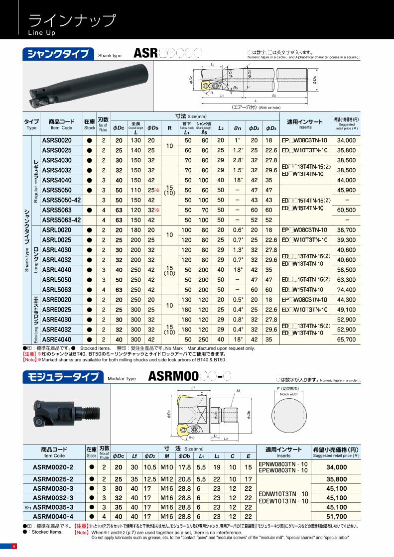
ラインナップLine Up
全長Overall length
LφDs R
首下Below neck
L1L2 φD2 φD3
シャンク長Shank lengthRs
φDc θn
レギュラー
ロング
エキストラロング
シャンクタイプ
20
25
29
29
40
50
50
50
50
20
25
29
29
40
50
50
20
25
29
29
40
20
25
30
32
40
50
50
63
63
20
25
30
32
40
50
63
20
25
30
32
40
1°
1.2°
2.8°
1.5°
18°
-
-
-
-
0.6°
0.7°
1.3°
0.7°
18°
-
-
0.5°
0.4°
0.8°
0.4°
18°
20
25
32
32
42
47
43
60
52
20
25
32
32
42
47
60
20
25
32
32
42
18
22.6
27.8
29.6
35
47
43
60
52
18
22.6
27.8
29.6
35
47
60
18
22.6
27.8
29.6
35
(Z)
(Z)
(Z)
(Z)
(Z)
φD
c
φD
s
L2
θn
φD
2
φD
3
L1
130
140
150
150
150
110
150
120
150
180
200
200
200
250
250
250
250
300
300
300
300
20
25
32
32
42
25※
42
32※
42
20
25
32
32
42
42
42
20
25
32
32
42
50
60
70
70
50
50
50
50
50
100
120
120
120
50
50
50
130
180
180
180
50
10
10
10
15(10)
15(10)
15(10)
80
80
80
80
100
60
100
70
100
80
80
80
80
200
200
200
120
120
120
120
250
34,000
35,800
38,500
38,500
44,000
45,900
-
60,500
-
38,700
39,300
40,600
40,600
58,500
63,300
74,400
44,300
49,100
52,900
52,900
65,700
ASRS0020ASRS0025ASRS4030ASRS4032ASRS4040ASRS5050ASRS5050-42
ASRL0020ASRL0025ASRL4030ASRL4032ASRL4040ASRL5050ASRL5063ASRE0020ASRE0025ASRE4030ASRE4032ASRE4040
ASRS5063ASRS5063-42
●
●
●
●
●
●
●
●
●
●
●
●
●
●
●
●
●
●
●
2
2
2
2
3
3
3
2
2
2
2
3
3
4
2
2
2
2
2
4
4
Shank typeシャンクタイプ ASR
φDc Lf R R a b●●
●
●
●●●
3434344556
5050606063638080
100100
50505050505070707070
19191919191932323232
15(10)
5555558888
22.22522.22522.22522.22522.22522.22531.7531.7531.7531.75
ED 15T4TN-15(Z)ED W15T4TN-10
内径インチサイズ
内径ミリサイズ
ED 13T4TN-15(Z)ED W13T4TN-10
ED 15T4TN-15(Z)ED W15T4TN-10
ED 13T4TN-15(Z)ED W13T4TN-10
ボアタイプ
● 4 50 50 20 6.3 22
● 4 60 50 20 6.3 22● 4 63 50 20 6.3 22● 5 80 70 22 7 27
ASR4050-3ASR4050-4ASR5060-3ASR5060-4ASR5063-3ASR5063-4ASR5080-4ASR5080-5ASR5100-5ASR5100-6
ASR4050M-4
ASR5060M-4ASR5063M-4ASR5080M-5ASR5100M-6 ● 6 100 70 25.5 8 32
8.48.48.48.48.48.4
12.712.712.712.7
10.4
10.410.412.414.4
φDb47475757606076769696
47
57607696
φd1φd17171717171726262626
17
17172026
φdφDb
φDc
R
R
Lf
ab
φd1
47,900 58,300 -60,600 -60,600 -91,900
109,000 124,000
58,300
60,600 60,600 91,900
124,000
ASR (M)-
寸法 Size(mm)
は数字が入ります。 Numeric figure in a circle .ASRM00 -
寸法 Size(mm) タイプType
商品コードItem Code No. of Flutes
刃数在庫Stock
Sha
nk ty
pe
Reg
ular
Long
Extra
Long
Inserts適用インサート
Bor
e ty
pe
●印:標準在庫品です。●:Stocked Items. 無印:受注生産品です。No Mark:Manufactured upon request only.
●印:標準在庫品です。●:Stocked Items. 無印:受注生産品です。No Mark:Manufactured upon request only.
【Note】※Marked shanks are available for both milling chucks and side lock arbors of BT40 & BT50.
【注意】アーバ用ねじは付属しません。【Note】Arbor screw is not included.
【注意】※印のシャンクはBT40,BT50のミ-リングチャックとサイドロックア-バでご使用できます。
inch
siz
em
m si
ze
希望小売価格(円)Suggested
retail price (¥)タイプ
Type商品コードItem Code No. of
Flutes
刃数在庫Stock Inserts
適用インサート 希望小売価格(円)Suggested
retail price (¥)
4

Parts部品番号
Modular Typeモジュラータイプ
Bore typeボアタイプ
(エアー穴付)(With air hole)
は数字、 は英文字が入ります。Numeric figure in a circle and Alphabetical character comes in a square
は数字、 は英文字が入ります。Numeric figure in a circle and Alphabetical character comes in a square
●印:標準在庫品です。●:Stocked Items.
【注意】※1と※2(P.7)をセットで使用すると干渉がありません。モジュラーミル及び専用シャンク、専用アーバの「工具端面」「モジュラーネジ部」にグリースなどの潤滑剤は塗布しないでください。【Note】When※1 and※2 (p.7) are used together as a set, there is no interference.
Do not apply lubricants such as grease, etc. to the "contact faces" and "modular screws" of the "modular mill", "special shanks" and "special arbor".
商品コードItem Code
在庫Stock
刃数No.ofFlute
ASRM0020-2
ASRM0025-2ASRM0030-3ASRM0032-3ASRM0035-3ASRM0040-4
34,000
35,80045,100 45,100 45,100 51,700
※1
●
●
●
●
●
●
2
23334
20
2530323540
30
3540404040
10.5
12.517171717
M10
M12M16M16M16M16
17.8
20.828.828.828.828.8
5.5
5.56666
19
2223232323
10
1012121212
15
1722222222
EPNW0803TN‐10EPEW0803TN‐10
EDNW10T3TN‐10EDEW10T3TN‐10
適用インサートInserts
寸 法 Size(mm)
E(切欠部巾)Notch width
φD
b
φD
c
CL f
L1R10 L2
M
φD
2
希望小売価格(円)Suggested retail price (¥)
Shape形状
部品名Parts
適用カッタCutter body
ASRM0020-2ASR S/L/E0020
ASR S/L/E0025
クランプねじClamp screw
242-141
555-141
クランプ駒セットClamp Piece set
ASR -
ASRM -
ASR M-
ASR S/L/E4ASR S/L5
412-141
440
550
440
2.9
4.9
2.9
CM5-147
CM3.5-141
1,650
1,650
105-T20
104-T15
1,720
1,670
820
A
B
形状ShapeA B
ドライバー/レンチScrew Driver / Wrench
ねじ焼き付き防止剤Screw anti-seizure agent
P-37
締付トルクFastening
torque(N・m)
希望小売価格(円)Suggested
retail price (¥)
希望小売価格(円)Suggested
retail price (¥)
希望小売価格(円)Suggested
retail price (¥)
希望小売価格(円)Suggested
retail price (¥)
L2Lf M C EL1φD2 φDbφDc
ラインナップLine Up
全長Overall length
LφDs R
首下Below neck
L1L2 φD2 φD3
シャンク長Shank lengthRs
φDc θn
レギュラー
ロング
エキストラロング
シャンクタイプ
20
25
29
29
40
50
50
50
50
20
25
29
29
40
50
50
20
25
29
29
40
20
25
30
32
40
50
50
63
63
20
25
30
32
40
50
63
20
25
30
32
40
1°
1.2°
2.8°
1.5°
18°
-
-
-
-
0.6°
0.7°
1.3°
0.7°
18°
-
-
0.5°
0.4°
0.8°
0.4°
18°
20
25
32
32
42
47
43
60
52
20
25
32
32
42
47
60
20
25
32
32
42
18
22.6
27.8
29.6
35
47
43
60
52
18
22.6
27.8
29.6
35
47
60
18
22.6
27.8
29.6
35
(Z)
(Z)
(Z)
(Z)
(Z)
φD
c
φD
s
L2
θn
φD
2
φD
3
L1
130
140
150
150
150
110
150
120
150
180
200
200
200
250
250
250
250
300
300
300
300
20
25
32
32
42
25※
42
32※
42
20
25
32
32
42
42
42
20
25
32
32
42
50
60
70
70
50
50
50
50
50
100
120
120
120
50
50
50
130
180
180
180
50
10
10
10
15(10)
15(10)
15(10)
80
80
80
80
100
60
100
70
100
80
80
80
80
200
200
200
120
120
120
120
250
34,000
35,800
38,500
38,500
44,000
45,900
-
60,500
-
38,700
39,300
40,600
40,600
58,500
63,300
74,400
44,300
49,100
52,900
52,900
65,700
ASRS0020ASRS0025ASRS4030ASRS4032ASRS4040ASRS5050ASRS5050-42
ASRL0020ASRL0025ASRL4030ASRL4032ASRL4040ASRL5050ASRL5063ASRE0020ASRE0025ASRE4030ASRE4032ASRE4040
ASRS5063ASRS5063-42
●
●
●
●
●
●
●
●
●
●
●
●
●
●
●
●
●
●
●
2
2
2
2
3
3
3
2
2
2
2
3
3
4
2
2
2
2
2
4
4
Shank typeシャンクタイプ ASR
φDc Lf R R a b●●
●
●
●●●
3434344556
5050606063638080
100100
50505050505070707070
19191919191932323232
15(10)
5555558888
22.22522.22522.22522.22522.22522.22531.7531.7531.7531.75
ED 15T4TN-15(Z)ED W15T4TN-10
内径インチサイズ
内径ミリサイズ
ED 13T4TN-15(Z)ED W13T4TN-10
ED 15T4TN-15(Z)ED W15T4TN-10
ED 13T4TN-15(Z)ED W13T4TN-10
ボアタイプ
● 4 50 50 20 6.3 22
● 4 60 50 20 6.3 22● 4 63 50 20 6.3 22● 5 80 70 22 7 27
ASR4050-3ASR4050-4ASR5060-3ASR5060-4ASR5063-3ASR5063-4ASR5080-4ASR5080-5ASR5100-5ASR5100-6
ASR4050M-4
ASR5060M-4ASR5063M-4ASR5080M-5ASR5100M-6 ● 6 100 70 25.5 8 32
8.48.48.48.48.48.4
12.712.712.712.7
10.4
10.410.412.414.4
φDb47475757606076769696
47
57607696
φd1φd17171717171726262626
17
17172026
φdφDb
φDc
R
R
Lf
ab
φd1
47,900 58,300 -60,600 -60,600 -91,900
109,000 124,000
58,300
60,600 60,600 91,900
124,000
ASR (M)-
寸法 Size(mm)
は数字が入ります。 Numeric figure in a circle .ASRM00 -
寸法 Size(mm) タイプType
商品コードItem Code No. of Flutes
刃数在庫Stock
Sha
nk ty
pe
Reg
ular
Long
Extra
Long
Inserts適用インサート
Bor
e ty
pe
●印:標準在庫品です。●:Stocked Items. 無印:受注生産品です。No Mark:Manufactured upon request only.
●印:標準在庫品です。●:Stocked Items. 無印:受注生産品です。No Mark:Manufactured upon request only.
【Note】※Marked shanks are available for both milling chucks and side lock arbors of BT40 & BT50.
【注意】アーバ用ねじは付属しません。【Note】Arbor screw is not included.
【注意】※印のシャンクはBT40,BT50のミ-リングチャックとサイドロックア-バでご使用できます。
inch
siz
em
m si
ze
希望小売価格(円)Suggested
retail price (¥)タイプ
Type商品コードItem Code No. of
Flutes
刃数在庫Stock Inserts
適用インサート 希望小売価格(円)Suggested
retail price (¥)
豊富な工具ラインナップであらゆる荒加工のニーズに対応します。 Handle a many kind of roughing machining needs with a plentiful lineup.
型式Type
特長 Feature ホルダー Holder インサート Insert プログラミング R
Programming R(mm)
最大 ap Maximum ap(mm)
経済性(コーナ数)
Economical(No. of corners)
高精度(削り残し小)high accuracy(Less uncut remnants)
高硬度対応
Supports for high-hardened steel
能率(刃数)Efficiency
(No. of Flutes)
刃径Tool dia(mm)
コーナ数No. of corners
形状Shape
内接円記号Inscribed
circle code
TD4N ◎ ◎ 〜50HRC
◎高能率多刃High Efficiency
multiflutes
φ16〜40 4 06 2.0 1.0
ASR 多刃Multi-Flutes ○ ○
〜62HRC高能率多刃High Efficiency
multiflutes
φ16〜66 206 2.0 1.5
12 3.0 2.0
ASRF-mini ○〜62HRC
○汎用 General φ20〜63 4 06 2.0 1.2
ASR ○ ○〜60HRC
○汎用 General φ20〜100 2 08〜15 3.0 2.0
ASRT ○ ○ ○〜62HRC
○汎用 General φ25〜100 3 09〜14 3.0 2.0
ASRF ◎ ○〜60HRC
○汎用 General φ32〜100 4 12 4.5 2.0
※工具仕様の詳細については総合カタログまたはホームページで確認をお願いします。For details of tool specifications, please check on catalog or website (http://www.mmc-hitachitool.co.jp)
当社高送り工具のラインナップ High-feed tools lineup for Mitsubishi Hitachi Tool.
5

The Shanks for Modular Millモジュラーミル専用シャンク
Insertsインサート
商品コード Item Code
ASC20-10.5-120-50ZASC20-10.5-170-90ZASC20-10.5-220-120ZASC20-10.5-270-150ZASC20-10.5-220-50ZASC20-10.5-270-50ZASC25-12.5-145-65ASC25-12.5-215-115ASC25-12.5-265-145ASC25-12.5-315-195ASC25-12.5-265-65ASC25-12.5-315-65ASC32-17-160-80ASC32-17-210-110ASC32-17-260-140ASC32-17-310-190ASC32-17-360-240ASC32-17-260-80ASC32-17-310-80ASC32-17-360-80
在庫Stock
●●●●●●●●●●●●●●●●●●●●
寸法 Size(mm)
φD2 M L3 LfL L2
5090
12015050
φD3
18.5
180 65250 115300 145350 195300 65
80
200 80350
250 110300 140350 190400300350400
145
250 220300 270
150 120
215
200 170
265
250 220
315
300 270
265
160315
210260310360260310360
240
L1
8012015018080
100150180230100120150180230280
120
Rs70 48,400
54,200 59,600 75,600 59,600 75,600 55,400 64,900 75,600 97,500 75,600 97,500 84,000 85,000
101,000 137,000 173,000 101,000 137,000 173,000
8010012017022080
100120120200
80250
100120120120180230280
適用カッタCutter body
タイプType
φ20※3
φ20※3
φ25※3
φ25※3
φ30※3φ32※3φ35
<φ40>φ30※3φ32※3φ35
<φ40>
18.5
12.5
12.5
M12
M12
10.5
10.5
M10
M10
23
23
17
17
M16
M16
35
30
30
35
40
40
28
28
φDs
20
20
25
25
32
32
φD4
19.5 A
備考Note
A
B
B
B
B
19.5
ー
ー
ー
ー
【注意】①※2と※1(P.5)をセットで使用すると干渉がありません。②市販のミ-リングチャック、焼ばめホルダーにて使用できます。③<φ40>寸法は、突き出し長さ200mm以下を目安にご使用下さい。④※3ではカッタ径がシャンク径より小さいため、シャンク首部の干渉が生じます。
①When※2 and※1 (p.5) are used together as a set, there is no interference.②Commercial milling chucks or shrink-fit holders can be used.③For the φ40 size, it is recommended that the protrusion length be 200mm or less.④For ※3, since the cutter diameter is smaller than the shank diameter, interference occurs at the shank.
【Note】
【注意】①市販のミ-リングチャックにて使用できます。②※3ではカッタ径がシャンク径より小さいため、シャンク首部の干渉が生じます。①Commercial milling chucks can be used.②For ※3, since the cutter diameter is smaller than the shank diameter, interference occurs at the shank.
【Note】
【注意】市販のミ-リングチャックにて使用できます。Commercial milling chucks can be used.【Note】
●印:標準在庫品です。●:Stocked Items.
Bタイプ B type
エア
ー穴
付 W
ith A
ir ho
le
Aタイプ A type
L 3
LL 1
L 2 RsL f
M
φD
s
φD
2
φD
4
φD
3
L 3
LL 1
L 2 RsL f
φD
s
φD
2 M
φD
3
:一般切削・第一推奨 General cutting, First recommended
:一般切削・第二推奨 General cutting, Second recommended
Fig-3ブレーカ付Breaker type
Fig-1標準形状
Standard shape
Fig-2凸形状
Convex shape type
■ 超硬シャンク Carbide Shank
ラインナップLine Up
PMKH
980
Fig-1
Fig-1
Fig-2
Fig-3
【注意】使い分け:R15は、突き出し量5Dc以下、R10は突き出し量4~5Dc以上を推奨致します。 GX2140は通電式タッチセンサーに反応しませんのでご注意ください。
R I T W
10 13.5 5.56 12.7
10 15 5.56 14
形状Shape
IW
TR R R
IW
T
IW
T
10 8.1 3.18 7.94
10 10 3.97 10
15 13.5 5.56 12.7
15 15 5.56 14
CY2
50
GF3
0
10 8.1 3.18 7.94●
●
●
●
●
●
●
●
●
●
●
●
●
●
●
●
●
●
●
●
●
●
●
●
●
●
●
●
●
●
●
●
△●
●
●
●
●
●
●
●
●
●
●
●
●
●
●
●
●
●
●
●
●
●
● 15 13.5 5.56 12.7
● 15 15 5.56 14
● 10 10 3.97 10
10 15 5.56 14
15 13.5 5.56 12.7
15 15 5.56 14
15 13.5 5.56 12.7
15 15 5.56 14
●
●
●
●
●
●
●
●
●
●
●
● 10 13.5 5.56 12.7
JP41
05 AJコートGXコートJSコート
CY250GF30
JS40
45
JM41
60
GX2
140
JP41
20
JS40
60
鋼
SUS等
FC・FCD
高硬度材
1,160
1,460
1,460
1,680
1,680
2,510
2,510
2,660
2,660
1,460
1,680
1,460
1,680
890
1,050
1,330
1,330
1,530
1,530
- -
- -
2,280
2,280
2,420
2,420
-
-
1,330
1,530
EPNW0803TN-10
EDNW10T3TN-10
EDNW13T4TN-10
EDNW13T4TN-15
EDNW15T4TN-10
EDNW15T4TN-15
EPEW0803TN-10
EDEW10T3TN-10
EDEW13T4TN-10
EDEW13T4TN-15
EDEW15T4TN-10
EDEW15T4TN-15
EDNW13T4TN-15Z
EDNW15T4TN-15Z
EDMT13T4TN-15
EDMT15T4TN-15
△印:在庫が無くなり次第受注生産品となります。
は数字が入ります。 Numeric figure in a circle .
△:Product will become a made-to-order product after current stock is exhausted.
【Note】 We recommend, R15 for over hung 5Dc or less; R10 for over hung 4~5Dc or more. Please note that the GX2140 does not cause a reaction in conductive touch sensors.
※2※2
※2※2
※2※2※2
L 3
L
L 1
L 2 Rs
L f
M
φD
s
φD
2
φD
3
商品コードItem Code
AS20-10.5-100-20AS25-12.5-115-35
AS32-17-110-30
在庫
Stoc
k
●
●
●
寸 法 Size (mm)
10.5
12.5
17
φD2 φD3
M10
M12
M16
M φDs 適用カ
ッタCu
tter b
ody
φ20※3
φ25※3
φ30※3φ32※3φ35φ40
○
○
○
L3 L L2 L1 RsLf130
150
150
100
115
110
30
35
40
20
35
30
50
70
70
80
80
80
18
23
28
20
25
32
エアー穴
有無Wit
h/witho
ut air h
ole
27,000
30,200
36,200
希望小売価格(円)Suggested
retail price (¥)
●印:標準在庫品です。 ●:Stocked Items.
●印:標準在庫品です。 ●:Stocked Items.
商品コードItem Code
AS42-17-360-90
在庫
Stoc
k
●
寸 法 Size (mm)
17
φD2 φD3
M16
M φDs 適用
カッタ
Cutte
r bod
y
φ30φ32φ35φ40
○
LL3 L2 L1 RsLf
400 40 67360 90 270 28 42
L3
L
L1L2 Rs
L f
M
φD
s
φD2
φD
3
■ 鋼シャンク Steel Shank
エアー穴
有無Wit
h/witho
ut air h
ole
69,000
希望小売価格(円)Suggested
retail price (¥)
■ 鋼シャンク Steel Shank
※首部及び全長は、ユーザ様にて追加工可能です。※For neck section or total length, additional machining to user specifications is possible.
希望小売価格(円)Suggested retail price (¥)
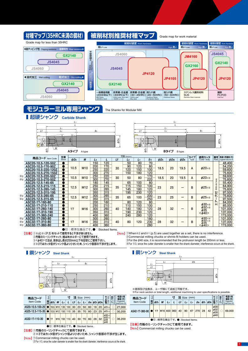
◀耐チッピング性 Chipping resistance 耐摩耗性 Wear resistance▶
JS4045
JS4060
GX2140
◀湿式加工 Wet cutting 乾式加工 Dry cutting▶
JS4045
JS4060
GX2140
一般構造用鋼(200HB以下)
Mild Steels(200HB or less)
炭素鋼・合金鋼(30HRC以下)
Carbon steel, Alloy steel(30HRC or less)
炭素鋼・合金鋼(30~45HRC)
Carbon steelAlloy steel
焼入れ鋼 (45~50HRC)
Hardened SteelsPre-Harden Steels
焼入れ鋼 (50~60HRC)
Hardened Steels
ステンレス鋼系材料SUSStainless Steel materials
鋳鉄FC,FCDCast iron
GX2140
JS4045
JS4045JS4060 JM4160
GX2160
低い Low High 高い被削材硬度 Work Hardness
不安定加工
安定加工
GX2140
JP4120JP4120
JP4105 JP4120
Sta
ble
mac
hini
ngU
nsta
ble
mac
hini
ng
低い Low High 高い被削材硬度 Work Hardness
低い Low High 高い被削材硬度 Work Hardness
Carbon steels
SUS, etc.
Hardened steels
希望小売価格(円)Suggested retail price(¥)
商品コードItem Code Cutter body
適用カッタ
寸法 Size(mm)
N
N級
N
N級
M
M級
E
E級
Tole
ranc
e C
lass
精度
Cコート
C-C
oate
d
Gコート
G-C
oate
d
GXコート
GX-
Coat
ed
AJコート
AJ-C
oate
d
JSコート
JS-C
oate
d
AJ,GX,JS Coated
●印:標準在庫品です。 ●:Stocked Items. 無印:受注生産品です。 No Mark:Manufactured upon request only.
Grade map for less than 35HRC
材種マップ(35HRC未満の鋼材) Grade map for work material被削材別推奨材種マップ
6
The Shanks for Modular Millモジュラーミル専用シャンク
Insertsインサート
商品コード Item Code
ASC20-10.5-120-50ZASC20-10.5-170-90ZASC20-10.5-220-120ZASC20-10.5-270-150ZASC20-10.5-220-50ZASC20-10.5-270-50ZASC25-12.5-145-65ASC25-12.5-215-115ASC25-12.5-265-145ASC25-12.5-315-195ASC25-12.5-265-65ASC25-12.5-315-65ASC32-17-160-80ASC32-17-210-110ASC32-17-260-140ASC32-17-310-190ASC32-17-360-240ASC32-17-260-80ASC32-17-310-80ASC32-17-360-80
在庫Stock
●●●●●●●●●●●●●●●●●●●●
寸法 Size(mm)
φD2 M L3 LfL L2
5090
12015050
φD3
18.5
180 65250 115300 145350 195300 65
80
200 80350
250 110300 140350 190400300350400
145
250 220300 270
150 120
215
200 170
265
250 220
315
300 270
265
160315
210260310360260310360
240
L1
8012015018080
100150180230100120150180230280
120
Rs70 48,400
54,200 59,600 75,600 59,600 75,600 55,400 64,900 75,600 97,500 75,600 97,500 84,000 85,000
101,000 137,000 173,000 101,000 137,000 173,000
8010012017022080
100120120200
80250
100120120120180230280
適用カッタCutter body
タイプType
φ20※3
φ20※3
φ25※3
φ25※3
φ30※3φ32※3φ35
<φ40>φ30※3φ32※3φ35
<φ40>
18.5
12.5
12.5
M12
M12
10.5
10.5
M10
M10
23
23
17
17
M16
M16
35
30
30
35
40
40
28
28
φDs
20
20
25
25
32
32
φD4
19.5 A
備考Note
A
B
B
B
B
19.5
ー
ー
ー
ー
【注意】①※2と※1(P.5)をセットで使用すると干渉がありません。②市販のミ-リングチャック、焼ばめホルダーにて使用できます。③<φ40>寸法は、突き出し長さ200mm以下を目安にご使用下さい。④※3ではカッタ径がシャンク径より小さいため、シャンク首部の干渉が生じます。
①When※2 and※1 (p.5) are used together as a set, there is no interference.②Commercial milling chucks or shrink-fit holders can be used.③For the φ40 size, it is recommended that the protrusion length be 200mm or less.④For ※3, since the cutter diameter is smaller than the shank diameter, interference occurs at the shank.
【Note】
【注意】①市販のミ-リングチャックにて使用できます。②※3ではカッタ径がシャンク径より小さいため、シャンク首部の干渉が生じます。①Commercial milling chucks can be used.②For ※3, since the cutter diameter is smaller than the shank diameter, interference occurs at the shank.
【Note】
【注意】市販のミ-リングチャックにて使用できます。Commercial milling chucks can be used.【Note】
●印:標準在庫品です。●:Stocked Items.
Bタイプ B type
エア
ー穴
付 W
ith A
ir ho
le
Aタイプ A type
L 3
LL 1
L 2 RsL f
M
φD
s
φD
2
φD
4
φD
3
L 3
LL 1
L 2 RsL f
φD
s
φD
2 M
φD
3
:一般切削・第一推奨 General cutting, First recommended
:一般切削・第二推奨 General cutting, Second recommended
Fig-3ブレーカ付Breaker type
Fig-1標準形状
Standard shape
Fig-2凸形状
Convex shape type
■ 超硬シャンク Carbide Shank
ラインナップLine Up
PMKH
980
Fig-1
Fig-1
Fig-2
Fig-3
【注意】使い分け:R15は、突き出し量5Dc以下、R10は突き出し量4~5Dc以上を推奨致します。 GX2140は通電式タッチセンサーに反応しませんのでご注意ください。
R I T W
10 13.5 5.56 12.7
10 15 5.56 14
形状Shape
IW
TR R R
IW
T
IW
T
10 8.1 3.18 7.94
10 10 3.97 10
15 13.5 5.56 12.7
15 15 5.56 14
CY2
50
GF3
0
10 8.1 3.18 7.94●
●
●
●
●
●
●
●
●
●
●
●
●
●
●
●
●
●
●
●
●
●
●
●
●
●
●
●
●
●
●
●
△●
●
●
●
●
●
●
●
●
●
●
●
●
●
●
●
●
●
●
●
●
●
● 15 13.5 5.56 12.7
● 15 15 5.56 14
● 10 10 3.97 10
10 15 5.56 14
15 13.5 5.56 12.7
15 15 5.56 14
15 13.5 5.56 12.7
15 15 5.56 14
●
●
●
●
●
●
●
●
●
●
●
● 10 13.5 5.56 12.7
JP41
05 AJコートGXコートJSコート
CY250GF30
JS40
45
JM41
60
GX2
140
JP41
20
JS40
60
鋼
SUS等
FC・FCD
高硬度材
1,160
1,460
1,460
1,680
1,680
2,510
2,510
2,660
2,660
1,460
1,680
1,460
1,680
890
1,050
1,330
1,330
1,530
1,530
- -
- -
2,280
2,280
2,420
2,420
-
-
1,330
1,530
EPNW0803TN-10
EDNW10T3TN-10
EDNW13T4TN-10
EDNW13T4TN-15
EDNW15T4TN-10
EDNW15T4TN-15
EPEW0803TN-10
EDEW10T3TN-10
EDEW13T4TN-10
EDEW13T4TN-15
EDEW15T4TN-10
EDEW15T4TN-15
EDNW13T4TN-15Z
EDNW15T4TN-15Z
EDMT13T4TN-15
EDMT15T4TN-15
△印:在庫が無くなり次第受注生産品となります。
は数字が入ります。 Numeric figure in a circle .
△:Product will become a made-to-order product after current stock is exhausted.
【Note】 We recommend, R15 for over hung 5Dc or less; R10 for over hung 4~5Dc or more. Please note that the GX2140 does not cause a reaction in conductive touch sensors.
※2※2
※2※2
※2※2※2
L 3
L
L 1
L 2 Rs
L f
M
φD
s
φD
2
φD
3
商品コードItem Code
AS20-10.5-100-20AS25-12.5-115-35
AS32-17-110-30
在庫
Stoc
k
●
●
●
寸 法 Size (mm)
10.5
12.5
17
φD2 φD3
M10
M12
M16
M φDs 適用カ
ッタCu
tter b
ody
φ20※3
φ25※3
φ30※3φ32※3φ35φ40
○
○
○
L3 L L2 L1 RsLf130
150
150
100
115
110
30
35
40
20
35
30
50
70
70
80
80
80
18
23
28
20
25
32
エアー穴
有無Wit
h/witho
ut air h
ole
27,000
30,200
36,200
希望小売価格(円)Suggested
retail price (¥)
●印:標準在庫品です。 ●:Stocked Items.
●印:標準在庫品です。 ●:Stocked Items.
商品コードItem Code
AS42-17-360-90
在庫
Stoc
k
●
寸 法 Size (mm)
17
φD2 φD3
M16
M φDs 適用
カッタ
Cutte
r bod
y
φ30φ32φ35φ40
○
LL3 L2 L1 RsLf
400 40 67360 90 270 28 42
L3
L
L1L2 Rs
L f
M
φD
s
φD2
φD
3
■ 鋼シャンク Steel Shank
エアー穴
有無Wit
h/witho
ut air h
ole
69,000
希望小売価格(円)Suggested
retail price (¥)
■ 鋼シャンク Steel Shank
※首部及び全長は、ユーザ様にて追加工可能です。※For neck section or total length, additional machining to user specifications is possible.
希望小売価格(円)Suggested retail price (¥)
◀耐チッピング性 Chipping resistance 耐摩耗性 Wear resistance▶
JS4045
JS4060
GX2140
◀湿式加工 Wet cutting 乾式加工 Dry cutting▶
JS4045
JS4060
GX2140
一般構造用鋼(200HB以下)
Mild Steels(200HB or less)
炭素鋼・合金鋼(30HRC以下)
Carbon steel, Alloy steel(30HRC or less)
炭素鋼・合金鋼(30~45HRC)
Carbon steelAlloy steel
焼入れ鋼 (45~50HRC)
Hardened SteelsPre-Harden Steels
焼入れ鋼 (50~60HRC)
Hardened Steels
ステンレス鋼系材料SUSStainless Steel materials
鋳鉄FC,FCDCast iron
GX2140
JS4045
JS4045JS4060 JM4160
GX2160
低い Low High 高い被削材硬度 Work Hardness
不安定加工
安定加工
GX2140
JP4120JP4120
JP4105 JP4120
Sta
ble
mac
hini
ngU
nsta
ble
mac
hini
ng
低い Low High 高い被削材硬度 Work Hardness
低い Low High 高い被削材硬度 Work Hardness
Carbon steels
SUS, etc.
Hardened steels
希望小売価格(円)Suggested retail price(¥)
商品コードItem Code Cutter body
適用カッタ
寸法 Size(mm)
N
N級
N
N級
M
M級
E
E級
Tole
ranc
e C
lass
精度
Cコート
C-C
oate
d
Gコート
G-C
oate
d
GXコート
GX-
Coat
ed
AJコート
AJ-C
oate
d
JSコート
JS-C
oate
d
AJ,GX,JS Coated
●印:標準在庫品です。 ●:Stocked Items. 無印:受注生産品です。 No Mark:Manufactured upon request only.
Grade map for less than 35HRC
材種マップ(35HRC未満の鋼材) Grade map for work material被削材別推奨材種マップ
7
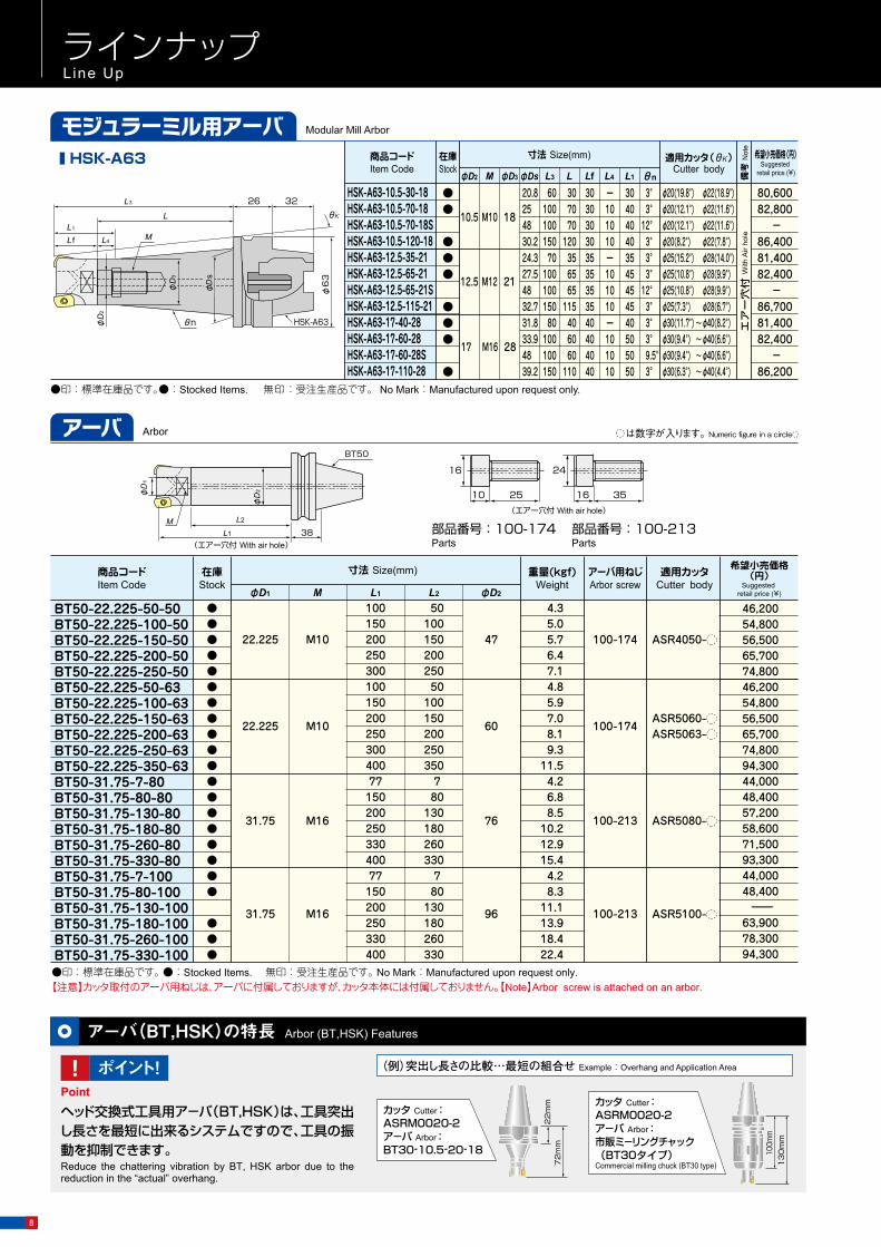
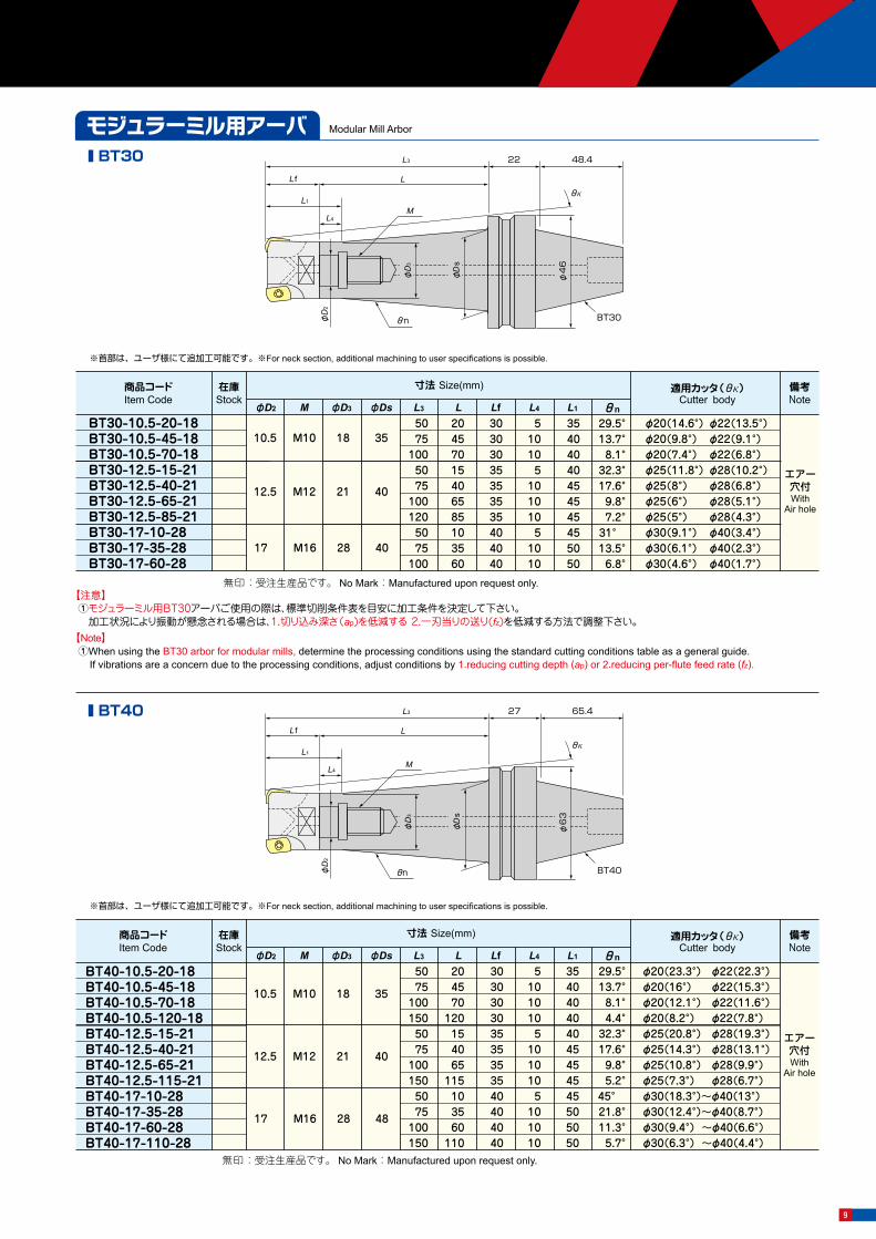
Modular Mill Arborモジュラーミル用アーバ
Arborアーバ
商品コード
BT30-10.5-20-18BT30-10.5-45-18BT30-10.5-70-18BT30-12.5-15-21BT30-12.5-40-21BT30-12.5-65-21BT30-12.5-85-21BT30-17-10-28BT30-17-35-28BT30-17-60-28
5075
1005075
1001205075
100
20457015406585103560
30303035353535404040
510105
1010105
1010
35404040454545455050
29.5°13.7° 8.1°32.3°17.6° 9.8° 7.2°31° 13.5° 6.8°
φ20(14.6°) φ22(13.5°)φ20(9.8°) φ22(9.1°)φ20(7.4°) φ22(6.8°)φ25(11.8°) φ28(10.2°)φ25(8°) φ28(6.8°)φ25(6°) φ28(5.1°)φ25(5°) φ28(4.3°)φ30(9.1°) φ40(3.4°)φ30(6.1°) φ40(2.3°)φ30(4.6°) φ40(1.7°)
Item Code在庫Stock
寸法 Size(mm)
φD2 M φD3 L3 L4φDs L L1Lf
適用カッタ(θκ)Cutter body
10.5
12.5
M10
M12
17 M16
18
21
28
35
40
40
θn
備考Note
エアー穴付With
Air hole
商品コード
BT40-10.5-20-18BT40-10.5-45-18BT40-10.5-70-18BT40-10.5-120-18BT40-12.5-15-21BT40-12.5-40-21BT40-12.5-65-21BT40-12.5-115-21BT40-17-10-28BT40-17-35-28BT40-17-60-28BT40-17-110-28
5075
1001505075
1001505075
100150
204570
120154065
115103560
110
303030303535353540404040
51010105
1010105
101010
354040404045454545505050
29.5°13.7°8.1°4.4°
32.3°17.6°9.8°5.2°
45° 21.8°11.3°5.7°
φ20(23.3°) φ22(22.3°)φ20(16°) φ22(15.3°)φ20(12.1°) φ22(11.6°)φ20(8.2°) φ22(7.8°)φ25(20.8°) φ28(19.3°)φ25(14.3°) φ28(13.1°)φ25(10.8°) φ28(9.9°)φ25(7.3°) φ28(6.7°)φ30(18.3°)~φ40(13°)φ30(12.4°)~φ40(8.7°)φ30(9.4°) ~φ40(6.6°)φ30(6.3°) ~φ40(4.4°)
Item Code在庫Stock
寸法 Size(mm)
φD2 M φD3 L3 L4φDs L L1Lf
適用カッタ(θκ)Cutter body
10.5
12.5
M10
M12
17 M16
18
21
28
35
40
48
θn
備考Note
無印:受注生産品です。 No Mark:Manufactured upon request only.
無印:受注生産品です。 No Mark:Manufactured upon request only.
エアー穴付With
Air hole
●印:標準在庫品です。 ●:Stocked Items. 無印:受注生産品です。 No Mark:Manufactured upon request only.【注意】カッタ取付のアーバ用ねじは、アーバに付属しておりますが、カッタ本体には付属しておりません。【Note】Arbor screw is attached on an arbor.
商品コード
BT50-22.225-50-50 BT50-22.225-100-50 BT50-22.225-150-50 BT50-22.225-200-50 BT50-22.225-250-50 BT50-22.225-50-63 BT50-22.225-100-63 BT50-22.225-150-63 BT50-22.225-200-63 BT50-22.225-250-63 BT50-22.225-350-63
BT50-31.75-80-80 BT50-31.75-130-80 BT50-31.75-180-80 BT50-31.75-260-80 BT50-31.75-330-80
BT50-31.75-80-100 BT50-31.75-130-100 BT50-31.75-180-100 BT50-31.75-260-100 BT50-31.75-330-100
Item Code在庫Stock
●●●●●●●●●●●
●●●●●
●
●●
●●
寸法 Size(mm)
φD1
22.225 M10
M
重量(kgf)Weight
6.47.14.85.97.08.19.3
11.5
6.8 BT50-31.75-7-80 ●
8.5
4.2
4.2
10.212.915.4
8.3 BT50-31.75-7-100
11.113.918.4
L1
100150200250300100150200250300400
15077
200250330400
15077
200250330400
L2
5010015020025050
100150200250350
807
130180260330
807
130180260330 22.4
アーバ用ねじArbor screw
100-174
適用カッタCutter body
ASR4050-
4.35.05.7
22.225 M10 100-174ASR5060- ASR5063-
31.75 M16 100-213 ASR5080-
31.75 M16
φD2
47
60
76
96 100-213 ASR5100-
部品番号:100-174 部品番号:100-213
10 25
16
16 35
24
Parts Parts38
BT50
L1
M L2
φD
2φD
1
(エアー穴付 With air hole)
θn
θκ
BT30
L3
L f
22
L4
L1
48.4
L
M
φD
2
φ4
6
φD
s
φD
3
【注意】①モジュラーミル用BT30アーバご使用の際は、標準切削条件表を目安に加工条件を決定して下さい。 加工状況により振動が懸念される場合は、1.切り込み深さ(ap)を低減する 2.一刃当りの送り(fz)を低減する方法で調整下さい。
【Note】①When using the BT30 arbor for modular mills, determine the processing conditions using the standard cutting conditions table as a general guide. If vibrations are a concern due to the processing conditions, adjust conditions by 1.reducing cutting depth (ap) or 2.reducing per-flute feed rate (fz).
※首部は、ユーザ様にて追加工可能です。※For neck section, additional machining to user specifications is possible.
※首部は、ユーザ様にて追加工可能です。※For neck section, additional machining to user specifications is possible.
商品コード
HSK-A63-10.5-30-18HSK-A63-10.5-70-18HSK-A63-10.5-70-18SHSK-A63-10.5-120-18HSK-A63-12.5-35-21HSK-A63-12.5-65-21HSK-A63-12.5-65-21SHSK-A63-12.5-115-21HSK-A63-17-40-28HSK-A63-17-60-28HSK-A63-17-60-28SHSK-A63-17-110-28
20.8254830.224.327.54832.731.833.94839.2
6010010015070
10010015080
100100150
307070
120356565
115406060
110
303030303535353540404040
304040403545454540505050
ー101010ー101010ー101010
3°3°
12°3°3°3°
12°3°3°3°9.5°3°
φ20(19.8°) φ22(18.9°) φ20(12.1°) φ22(11.6°) φ20(12.1°) φ22(11.6°) φ20(8.2°) φ22(7.8°) φ25(15.2°) φ28(14.0°) φ25(10.8°) φ28(9.9°) φ25(10.8°) φ28(9.9°) φ25(7.3°) φ28(6.7°) φ30(11.7°) ~ φ40(8.2°) φ30(9.4°) ~ φ40(6.6°) φ30(9.4°) ~ φ40(6.6°) φ30(6.3°) ~ φ40(4.4°)
Item Code在庫Stock
●●
●●●
●●●
●
寸法 Size(mm)
φD2 M φD3 L3 L4φDs L L1Lf
適用カッタ(θκ)Cutter body
10.5
12.5
M10
M12
17 M16
18
21
28
θn 備考
Not
e
●印:標準在庫品です。●:Stocked Items. 無印:受注生産品です。 No Mark:Manufactured upon request only.
θn BT40
L3
L f
27
L4
L1
65.4
L
M
φD
2
φ6
3
φD
s
φD
3
θκ
M
θn
L3 26
φ6
3
L
L4L fL1
32
φD
2
φD
s
φD
3
HSK-A63
θκ
は数字が入ります。 Numeric figure in a circle
(エアー穴付 With air hole)
■ HSK-A63 ■ BT30
■ BT40
80,600 82,800
-86,400 81,400 82,400
-86,700 81,400 82,400
-86,200
希望小売価格(円)Suggested
retail price (¥)
希望小売価格(円)
Suggested retail price (¥)
エア
ー穴
付 W
ith A
ir ho
le
46,200 54,800 56,500 65,700 74,800 46,200 54,800 56,500 65,700 74,800 94,300 44,000 48,400 57,200 58,600 71,500 93,300 44,000 48,400 -
63,900 78,300 94,300
ラインナップLine Up
Modular Mill Arborモジュラーミル用アーバ
ヘッド交換式工具用ア-バ(BT,HSK)は、工具突出し長さを最短に出来るシステムですので、工具の振動を抑制できます。Reduce the chattering vibration by BT, HSK arbor due to the reduction in the “actual” overhang.
カッタ Cutter :ASRM0020-2ア-バ Arbor :BT30‐10.5‐20‐18
カッタ Cutter :ASRM0020-2ア-バ Arbor :市販ミ-リングチャック(BT30タイプ)Commercial milling chuck (BT30 type) 1
30
mm
100m
m
72
mm
22
mm
ア-バ(BT,HSK)の特長 Arbor (BT,HSK) Features
! ポイント!Point
(例)突出し長さの比較…最短の組合せ Example : Overhang and Application Area
8
Modular Mill Arborモジュラーミル用アーバ
Arborアーバ
商品コード
BT30-10.5-20-18BT30-10.5-45-18BT30-10.5-70-18BT30-12.5-15-21BT30-12.5-40-21BT30-12.5-65-21BT30-12.5-85-21BT30-17-10-28BT30-17-35-28BT30-17-60-28
5075
1005075
1001205075
100
20457015406585103560
30303035353535404040
510105
1010105
1010
35404040454545455050
29.5°13.7° 8.1°32.3°17.6° 9.8° 7.2°31° 13.5° 6.8°
φ20(14.6°) φ22(13.5°)φ20(9.8°) φ22(9.1°)φ20(7.4°) φ22(6.8°)φ25(11.8°) φ28(10.2°)φ25(8°) φ28(6.8°)φ25(6°) φ28(5.1°)φ25(5°) φ28(4.3°)φ30(9.1°) φ40(3.4°)φ30(6.1°) φ40(2.3°)φ30(4.6°) φ40(1.7°)
Item Code在庫Stock
寸法 Size(mm)
φD2 M φD3 L3 L4φDs L L1Lf
適用カッタ(θκ)Cutter body
10.5
12.5
M10
M12
17 M16
18
21
28
35
40
40
θn
備考Note
エアー穴付With
Air hole
商品コード
BT40-10.5-20-18BT40-10.5-45-18BT40-10.5-70-18BT40-10.5-120-18BT40-12.5-15-21BT40-12.5-40-21BT40-12.5-65-21BT40-12.5-115-21BT40-17-10-28BT40-17-35-28BT40-17-60-28BT40-17-110-28
5075
1001505075
1001505075
100150
204570
120154065
115103560
110
303030303535353540404040
51010105
1010105
101010
354040404045454545505050
29.5°13.7°8.1°4.4°
32.3°17.6°9.8°5.2°
45° 21.8°11.3°5.7°
φ20(23.3°) φ22(22.3°)φ20(16°) φ22(15.3°)φ20(12.1°) φ22(11.6°)φ20(8.2°) φ22(7.8°)φ25(20.8°) φ28(19.3°)φ25(14.3°) φ28(13.1°)φ25(10.8°) φ28(9.9°)φ25(7.3°) φ28(6.7°)φ30(18.3°)~φ40(13°)φ30(12.4°)~φ40(8.7°)φ30(9.4°) ~φ40(6.6°)φ30(6.3°) ~φ40(4.4°)
Item Code在庫Stock
寸法 Size(mm)
φD2 M φD3 L3 L4φDs L L1Lf
適用カッタ(θκ)Cutter body
10.5
12.5
M10
M12
17 M16
18
21
28
35
40
48
θn
備考Note
無印:受注生産品です。 No Mark:Manufactured upon request only.
無印:受注生産品です。 No Mark:Manufactured upon request only.
エアー穴付With
Air hole
●印:標準在庫品です。 ●:Stocked Items. 無印:受注生産品です。 No Mark:Manufactured upon request only.【注意】カッタ取付のアーバ用ねじは、アーバに付属しておりますが、カッタ本体には付属しておりません。【Note】Arbor screw is attached on an arbor.
商品コード
BT50-22.225-50-50 BT50-22.225-100-50 BT50-22.225-150-50 BT50-22.225-200-50 BT50-22.225-250-50 BT50-22.225-50-63 BT50-22.225-100-63 BT50-22.225-150-63 BT50-22.225-200-63 BT50-22.225-250-63 BT50-22.225-350-63
BT50-31.75-80-80 BT50-31.75-130-80 BT50-31.75-180-80 BT50-31.75-260-80 BT50-31.75-330-80
BT50-31.75-80-100 BT50-31.75-130-100 BT50-31.75-180-100 BT50-31.75-260-100 BT50-31.75-330-100
Item Code在庫Stock
●●●●●●●●●●●
●●●●●
●
●●
●●
寸法 Size(mm)
φD1
22.225 M10
M
重量(kgf)Weight
6.47.14.85.97.08.19.3
11.5
6.8 BT50-31.75-7-80 ●
8.5
4.2
4.2
10.212.915.4
8.3 BT50-31.75-7-100
11.113.918.4
L1
100150200250300100150200250300400
15077
200250330400
15077
200250330400
L2
5010015020025050
100150200250350
807
130180260330
807
130180260330 22.4
アーバ用ねじArbor screw
100-174
適用カッタCutter body
ASR4050-
4.35.05.7
22.225 M10 100-174ASR5060- ASR5063-
31.75 M16 100-213 ASR5080-
31.75 M16
φD2
47
60
76
96 100-213 ASR5100-
部品番号:100-174 部品番号:100-213
10 25
16
16 35
24
Parts Parts38
BT50
L1
M L2
φD
2φD
1
(エアー穴付 With air hole)
θn
θκ
BT30
L3
L f
22
L4
L1
48.4
L
M
φD
2
φ4
6
φD
s
φD
3
【注意】①モジュラーミル用BT30アーバご使用の際は、標準切削条件表を目安に加工条件を決定して下さい。 加工状況により振動が懸念される場合は、1.切り込み深さ(ap)を低減する 2.一刃当りの送り(fz)を低減する方法で調整下さい。
【Note】①When using the BT30 arbor for modular mills, determine the processing conditions using the standard cutting conditions table as a general guide. If vibrations are a concern due to the processing conditions, adjust conditions by 1.reducing cutting depth (ap) or 2.reducing per-flute feed rate (fz).
※首部は、ユーザ様にて追加工可能です。※For neck section, additional machining to user specifications is possible.
※首部は、ユーザ様にて追加工可能です。※For neck section, additional machining to user specifications is possible.
商品コード
HSK-A63-10.5-30-18HSK-A63-10.5-70-18HSK-A63-10.5-70-18SHSK-A63-10.5-120-18HSK-A63-12.5-35-21HSK-A63-12.5-65-21HSK-A63-12.5-65-21SHSK-A63-12.5-115-21HSK-A63-17-40-28HSK-A63-17-60-28HSK-A63-17-60-28SHSK-A63-17-110-28
20.8254830.224.327.54832.731.833.94839.2
6010010015070
10010015080
100100150
307070
120356565
115406060
110
303030303535353540404040
304040403545454540505050
ー101010ー101010ー101010
3°3°
12°3°3°3°
12°3°3°3°9.5°3°
φ20(19.8°) φ22(18.9°) φ20(12.1°) φ22(11.6°) φ20(12.1°) φ22(11.6°) φ20(8.2°) φ22(7.8°) φ25(15.2°) φ28(14.0°) φ25(10.8°) φ28(9.9°) φ25(10.8°) φ28(9.9°) φ25(7.3°) φ28(6.7°) φ30(11.7°) ~ φ40(8.2°) φ30(9.4°) ~ φ40(6.6°) φ30(9.4°) ~ φ40(6.6°) φ30(6.3°) ~ φ40(4.4°)
Item Code在庫Stock
●●
●●●
●●●
●
寸法 Size(mm)
φD2 M φD3 L3 L4φDs L L1Lf
適用カッタ(θκ)Cutter body
10.5
12.5
M10
M12
17 M16
18
21
28
θn 備考
Not
e
●印:標準在庫品です。●:Stocked Items. 無印:受注生産品です。 No Mark:Manufactured upon request only.
θn BT40
L3
L f
27
L4
L1
65.4
L
M
φD
2
φ6
3
φD
s
φD
3
θκ
M
θn
L3 26
φ6
3
L
L4L fL1
32
φD
2
φD
s
φD
3
HSK-A63
θκ
は数字が入ります。 Numeric figure in a circle
(エアー穴付 With air hole)
■ HSK-A63 ■ BT30
■ BT40
80,600 82,800
-86,400 81,400 82,400
-86,700 81,400 82,400
-86,200
希望小売価格(円)Suggested
retail price (¥)
希望小売価格(円)
Suggested retail price (¥)
エア
ー穴
付 W
ith A
ir ho
le
46,200 54,800 56,500 65,700 74,800 46,200 54,800 56,500 65,700 74,800 94,300 44,000 48,400 57,200 58,600 71,500 93,300 44,000 48,400 -
63,900 78,300 94,300
ラインナップLine Up
Modular Mill Arborモジュラーミル用アーバ
ヘッド交換式工具用ア-バ(BT,HSK)は、工具突出し長さを最短に出来るシステムですので、工具の振動を抑制できます。Reduce the chattering vibration by BT, HSK arbor due to the reduction in the “actual” overhang.
カッタ Cutter :ASRM0020-2ア-バ Arbor :BT30‐10.5‐20‐18
カッタ Cutter :ASRM0020-2ア-バ Arbor :市販ミ-リングチャック(BT30タイプ)Commercial milling chuck (BT30 type) 1
30
mm
100m
m
72
mm
22
mm
ア-バ(BT,HSK)の特長 Arbor (BT,HSK) Features
! ポイント!Point
(例)突出し長さの比較…最短の組合せ Example : Overhang and Application Area
9

ラインナップLine Up
剛性値について About the rigidity valueS1kgf
(μm)
(9.8N)
S
■ Standard accessories
● Coolant duct(HSK) ■ Caution ● The Modular Mill is not a standard accessory.
Pull stud is not a standard accesorry.Please check your Modular Mills for conformance to the dimensions.
●
●
■ 標準付属品■ 注 意 事 項
•クーラントダクト(HSK-A)•モジュラーミルは付属しません。•プルスタッドは付属しておりません。•ご使用になるモジュラーミルが取付可能か「モジュラーミル取付部」で寸法をご確認ください。
モジュラーミル先端に1kgf・m(9.8N)の曲げ荷重をかけた時のホルダと工具全体がたわむ量を表しています。数値が小さい程、剛性があり精度の高い加工が可能です。
A rigidity value represents the amount of deflection for the entire holder and tool when a bending load of 1 kgf (9.8 N) is applied to the tip of the tool. The smaller the numerical value is, the higher the rigidity and the more accurate the machining.
10
5L1
φC2
ML
φC1 φC
モジュラーミル 取付け部Dimensions for the Modular Mill mounting
φD
H1
10
G
H ■注意事項 Caution●
●
●
●
一部取付けできない交換式工具があります。取付け可能か「交換式工具取付部」で寸法を確認いただくか、弊社までお問合わせください。※の商品は、条件を工具の推奨条件の半分程度に落としてご使用ください。機械とシャンクとの結合力に比べ、切削抵抗が大きくなり、ホルダシャンク部でフレッチング現象またはホルダの抜けが発生します。Some of the indexable end mills cannot be attached to the RED screw arbor. Please check your indexable end mills for conformance to the dimensions, or please contact Mitsubishi Hitachi Tool Engineering, Ltd.Because cutting resistance is greater than the tool holder connection force associated with the machine spindle, please reduce the recommended cutting conditions by 50% for the RED screw arbors marked with ※. Otherwise, the tool holder shank may experience fretting corrosion or fall out of the machine spindle.
レッドスクリューアーバ Red screw arbor
商品コードItem Code
在庫 Stock
寸法 Size (mm) 重量(kg) Weight
剛性値(μm)Rigidity valueSG φD H H1 φC L M L1 φC1 φC2
BT50-RSG10-285-M140M10 10.5 22 6.5 19
285140
14536 38
5.0 5.8BT50-RSG10-315-M140 315 175 6.0 5.8BT50-RSG12-140-M25
M12 12.5 22 6 24
14025
115
43 45
4.6 0.2BT50-RSG12-170-M25 170 145 5.0 0.3BT50-RSG12-200-M25 200 175 5.8 0.4BT50-RSG12-165-M50 165
50115 4.7 0.5
BT50-RSG12-195-M50 195 145 5.1 0.6BT50-RSG12-225-M50 225 175 5.9 0.6BT50-RSG12-190-M75 190
75115 4.9 0.8
BT50-RSG12-220-M75 220 145 5.3 1.0BT50-RSG12-250-M75 250 175 6.1 1.0BT50-RSG12-215-M100 215
100115 5.0 1.3
BT50-RSG12-245-M100 245 145 5.4 1.5BT50-RSG12-275-M100 275 175 6.2 1.6BT50-RSG12-240-M125 240
125115 5.2 2.1
BT50-RSG12-270-M125 270 145 5.6 2.3BT50-RSG12-300-M125 300 175 6.4 2.4BT50-RSG12-265-M150 265
150115 5.3 3.0
BT50-RSG12-295-M150 295 145 5.7 3.3BT50-RSG12-325-M150 325 175 6.5 3.4BT50-RSG12-290-M175 290
175115 5.5 4.2
BT50-RSG12-320-M175 320 145 5.9 4.6BT50-RSG12-350-M175 350 175 6.7 4.6BT50-RSG16-140-M25
M16 17 25 6 29
14025
115
52 54
4.8 0.2BT50-RSG16-170-M25 170 145 5.4 0.2BT50-RSG16-200-M25 200 175 6.6 0.2BT50-RSG16-165-M50 165
50115 5.0 0.3
BT50-RSG16-195-M50 195 145 5.6 0.4BT50-RSG16-225-M50 225 175 6.8 0.4BT50-RSG16-190-M75 190
75115 5.3 0.5
BT50-RSG16-220-M75 220 145 5.9 0.6BT50-RSG16-250-M75 250 175 7.0 0.6BT50-RSG16-215-M100 215
100115 5.5 0.7
BT50-RSG16-245-M100 245 145 6.1 0.9BT50-RSG16-275-M100 275 175 7.2 0.9BT50-RSG16-240-M125 240
125115 5.7 1.1
BT50-RSG16-270-M125 270 145 6.3 1.3BT50-RSG16-300-M125 300 175 7.4 1.3BT50-RSG16-265-M150 265
150115 5.9 1.6
BT50-RSG16-295-M150 295 145 6.5 1.8BT50-RSG16-325-M150 325 175 7.7 1.8BT50-RSG16-290-M175 290
175115 6.1 2.2
BT50-RSG16-320-M175 320 145 6.7 2.4BT50-RSG16-350-M175 350 175 7.9 2.5BT50-RSG16-315-M200 315
200115 6.3 3.0
BT50-RSG16-345-M200 345 145 6.9 3.2BT50-RSG16-375-M200 375 175 8.1 3.3BT50-RSG16-340-M225 340
225115 6.5 3.9
BT50-RSG16-370-M225 370 145 7.1 4.1BT50-RSG16-400-M225 400 175 8.3 4.2
商品コードItem Code
在庫 Stock
寸法 Size (mm) 重量(kg) Weight
剛性値(μm)Rigidity valueSG φD H H1 φC L M L1 φC1 φC2
BT40-RSG10-125-M25
M10 10.5 22 6.5 19
12525
100
36 38
1.8 0.4BT40-RSG10-155-M25 155 130 2.2 0.5BT40-RSG10-185-M25 185 160 2.4 0.7BT40-RSG10-150-M50 150
50100 1.9 0.8
BT40-RSG10-180-M50 180 130 2.3 1.0BT40-RSG10-210-M50 210 160 2.5 1.2BT40-RSG10-175-M75 175
75100 2.0 1.6
BT40-RSG10-205-M75 205 130 2.4 1.8BT40-RSG10-235-M75 235 160 2.6 2.0BT40-RSG10-200-M100 200
100100 2.0 2.7
BT40-RSG10-230-M100 230 130 2.4 3.0BT40-RSG10-260-M100 260 160 2.6 3.3BT40-RSG10-220-M120 220
120100 2.1 4.0
BT40-RSG10-250-M120 250 130 2.5 4.3BT40-RSG10-280-M120 280 160 2.7 4.6BT40-RSG12-125-M25
M12 12.5 22 6 24
12525
100
43 45
2.0 0.3BT40-RSG12-155-M25 155 130 2.4 0.4BT40-RSG12-185-M25 185 160 2.7 0.5BT40-RSG12-150-M50 150
50100 2.1 0.5
BT40-RSG12-180-M50 180 130 2.5 0.7BT40-RSG12-210-M50 210 160 2.8 0.9BT40-RSG12-175-M75 175
75100 2.3 0.9
BT40-RSG12-205-M75 205 130 2.7 1.1BT40-RSG12-235-M75 235 160 3.0 1.3BT40-RSG12-200-M100 200
100100 2.4 1.4
BT40-RSG12-230-M100 230 130 2.8 1.6BT40-RSG12-260-M100 260 160 3.1 1.9BT40-RSG12-225-M125 225
125100 2.6 2.1
BT40-RSG12-255-M125 255 130 3.0 2.4BT40-RSG12-285-M125 285 160 3.3 2.8BT40-RSG16-125-M25
M16 17 25 6 29
125 25
100 52 54
2.6 0.2BT40-RSG16-150-M50 150 50 2.8 0.3BT40-RSG16-175-M75 175 75 3.0 0.5BT40-RSG16-200-M100 200 100 3.2 0.8BT40-RSG16-225-M125 ※ 225 125 3.4 1.2BT50-RSG10-140-M25
M10 10.5 22 6.5 19
14025
115
36 38
4.3 0.4BT50-RSG10-170-M25 170 145 4.6 0.5BT50-RSG10-200-M25 200 175 5.6 0.5BT50-RSG10-165-M50 165
50115 4.4 0.8
BT50-RSG10-195-M50 195 145 4.7 0.9BT50-RSG10-225-M50 225 175 5.7 1.0BT50-RSG10-190-M75 190
75115 4.5 1.6
BT50-RSG10-220-M75 220 145 4.8 1.7BT50-RSG10-250-M75 250 175 5.8 1.8BT50-RSG10-215-M100 215
100115 4.5 2.7
BT50-RSG10-245-M100 245 145 4.8 2.9BT50-RSG10-275-M100 275 175 5.8 2.9BT50-RSG10-235-M120 235
120115 4.6 3.9
BT50-RSG10-265-M120 265 145 4.9 4.2BT50-RSG10-295-M120 295 175 5.9 4.2BT50-RSG10-255-M140 255 140 115 4.7 5.5
BT4
0B
T50
BT5
0

ラインナップLine Up
剛性値について About the rigidity valueS1kgf
(μm)
(9.8N)
S
■ Standard accessories
● Coolant duct(HSK) ■ Caution ● The Modular Mill is not a standard accessory.
Pull stud is not a standard accesorry.Please check your Modular Mills for conformance to the dimensions.
●
●
■ 標準付属品■ 注 意 事 項
•クーラントダクト(HSK-A)•モジュラーミルは付属しません。•プルスタッドは付属しておりません。•ご使用になるモジュラーミルが取付可能か「モジュラーミル取付部」で寸法をご確認ください。
モジュラーミル先端に1kgf・m(9.8N)の曲げ荷重をかけた時のホルダと工具全体がたわむ量を表しています。数値が小さい程、剛性があり精度の高い加工が可能です。
A rigidity value represents the amount of deflection for the entire holder and tool when a bending load of 1 kgf (9.8 N) is applied to the tip of the tool. The smaller the numerical value is, the higher the rigidity and the more accurate the machining.
11
無印:受注生産品です。No mark:Manufactured upon request only. 納期は受注後10日程度になります。Delivery time is about ten days after an order received.
商品コードItem Code
在庫 Stock
寸法 Size (mm) 重量(kg) Weight
剛性値(μm)Rigidity valueSG φD H H1 φC L M L1 φC1 φC2
A63-RSG10-125-M25
M10 10.5 22 6.5 19
12525
100
36 38
1.6 0.4A63-RSG10-155-M25 155 130 1.9 0.5A63-RSG10-185-M25 185 160 2.3 0.6A63-RSG10-150-M50 150
50100 1.7 0.8
A63-RSG10-180-M50 180 130 2.0 1.0A63-RSG10-210-M50 210 160 2.4 1.2A63-RSG10-175-M75 175
75100 1.8 1.6
A63-RSG10-205-M75 205 130 2.1 1.8A63-RSG10-235-M75 235 160 2.5 2.0A63-RSG10-200-M100 200
100100 1.8 2.7
A63-RSG10-230-M100 230 130 2.1 2.9A63-RSG10-260-M100 260 160 2.5 3.2A63-RSG10-220-M120 220
120100 1.9 4.0
A63-RSG10-250-M120 250 130 2.2 4.2A63-RSG10-280-M120 280 160 2.6 4.5A63-RSG10-240-M140 240
140100 2.0 5.6
A63-RSG10-270-M140 270 130 2.3 5.9A63-RSG10-300-M140 300 160 2.7 6.2A63-RSG12-125-M25
M12 12.5 22 6 24
12525
100
43 45
1.9 0.3A63-RSG12-155-M25 155 130 2.3 0.4A63-RSG12-185-M25 185 160 2.7 0.5A63-RSG12-150-M50 150
50100 2.0 0.5
A63-RSG12-180-M50 180 130 2.4 0.6A63-RSG12-210-M50 210 160 2.8 0.8A63-RSG12-175-M75 175
75100 2.2 0.9
A63-RSG12-205-M75 205 130 2.6 1.0A63-RSG12-235-M75 235 160 3.0 1.3A63-RSG12-200-M100 200
100100 2.3 1.4
A63-RSG12-230-M100 230 130 2.7 1.6A63-RSG12-260-M100 260 160 3.1 1.9A63-RSG12-225-M125 225
125100 2.5 2.1
A63-RSG12-255-M125 255 130 2.9 2.4A63-RSG12-285-M125 285 160 3.3 2.7A63-RSG12-250-M150 250
150100 2.6 3.1
A63-RSG12-280-M150 280 130 3.0 3.4A63-RSG12-310-M150 310 160 3.4 3.8A63-RSG16-140-M25
M16 17 25 6 29
140 25
115 52 54
2.8 0.2A63-RSG16-165-M50 165 50 3.2 0.4A63-RSG16-190-M75 190 75 3.6 0.6A63-RSG16-215-M100 215 100 2.8 0.9A63-RSG16-240-M125 ※ 240 125 2.8 1.3A63-RSG16-265-M150 ※ 265 150 3.2 1.9A63-RSG16-290-M175 ※ 290 175 3.6 2.5A100-RSG10-140-M25
M10 10.5 22 6.5 19
14025
115
36 38
3.1 0.4A100-RSG10-170-M25 170 145 3.5 0.5A100-RSG10-200-M25 200 175 4.4 0.5A100-RSG10-165-M50 165
50115 3.2 0.8
A100-RSG10-195-M50 195 145 3.6 1.0A100-RSG10-225-M50 225 175 4.5 1.0A100-RSG10-190-M75 190
75115 3.3 1.6
A100-RSG10-220-M75 220 145 3.7 1.8A100-RSG10-250-M75 250 175 4.6 1.8A100-RSG10-215-M100 215
100115 3.3 2.7
A100-RSG10-245-M100 245 145 3.7 2.9A100-RSG10-275-M100 275 175 4.6 2.9
商品コードItem Code
在庫 Stock
寸法 Size (mm) 重量(kg) Weight
剛性値(μm)Rigidity valueSG φD H H1 φC L M L1 φC1 φC2
A100-RSG10-235-M120
M10 10.5 22 6.5 19
235120
115
36 38
3.4 4.0A100-RSG10-265-M120 265 145 3.8 4.2A100-RSG10-295-M120 295 175 4.7 4.2A100-RSG10-255-M140 255
140115 3.5 5.6
A100-RSG10-285-M140 285 145 3.9 5.8A100-RSG10-315-M140 315 175 4.8 5.8
A100-RSG12-140-M25
M12 12.5 22 6 24
14025
115
43 45
3.4 0.3A100-RSG12-170-M25 170 145 3.7 0.4A100-RSG12-200-M25 200 175 4.7 0.4A100-RSG12-165-M50 165
50115 3.5 0.5
A100-RSG12-195-M50 195 145 3.8 0.6A100-RSG12-225-M50 225 175 4.8 0.6A100-RSG12-190-M75 190
75115 3.7 0.8
A100-RSG12-220-M75 220 145 4.0 1.0A100-RSG12-250-M75 250 175 5.0 1.0A100-RSG12-215-M100 215
100115 3.8 1.4
A100-RSG12-245-M100 245 145 4.1 1.6A100-RSG12-275-M100 275 175 5.1 1.6A100-RSG12-240-M125 240
125115 4.0 2.1
A100-RSG12-270-M125 270 145 4.3 2.4A100-RSG12-300-M125 300 175 5.3 2.4A100-RSG12-265-M150 265
150115 4.1 3.0
A100-RSG12-295-M150 295 145 4.4 3.4A100-RSG12-325-M150 325 175 5.4 3.4A100-RSG12-290-M175 290
175115 4.3 4.3
A100-RSG12-320-M175 320 145 4.6 4.6A100-RSG12-350-M175 350 175 5.6 4.6
A100-RSG16-140-M25
M16 17 25 6 29
14025
115
52 54
4.0 0.2A100-RSG16-170-M25 170 145 4.5 0.2A100-RSG16-200-M25 200 175 5.7 0.2A100-RSG16-165-M50 165
50115 4.2 0.3
A100-RSG16-195-M50 195 145 4.7 0.4A100-RSG16-225-M50 225 175 5.9 0.4A100-RSG16-190-M75 190
75115 4.5 0.5
A100-RSG16-220-M75 220 145 5.0 0.6A100-RSG16-250-M75 250 175 6.1 0.6A100-RSG16-215-M100 215
100115 4.7 0.8
A100-RSG16-245-M100 245 145 5.2 0.9A100-RSG16-275-M100 275 175 6.3 0.9A100-RSG16-240-M125 240
125115 4.9 1.1
A100-RSG16-270-M125 270 145 5.4 1.3A100-RSG16-300-M125 300 175 6.5 1.3A100-RSG16-265-M150 265
150115 5.1 1.6
A100-RSG16-295-M150 295 145 5.6 1.8A100-RSG16-325-M150 325 175 6.7 1.8A100-RSG16-290-M175 290
175115 5.3 2.2
A100-RSG16-320-M175 320 145 5.8 2.4A100-RSG16-350-M175 350 175 7.0 2.5A100-RSG16-315-M200 315
200115 5.5 3.0
A100-RSG16-345-M200 345 145 6.0 3.2A100-RSG16-375-M200 375 175 7.2 3.3A100-RSG16-340-M225 340
225115 5.7 3.9
A100-RSG16-370-M225 370 145 6.3 4.2A100-RSG16-400-M225 400 175 7.4 4.2
A63
A10
0
A10
0
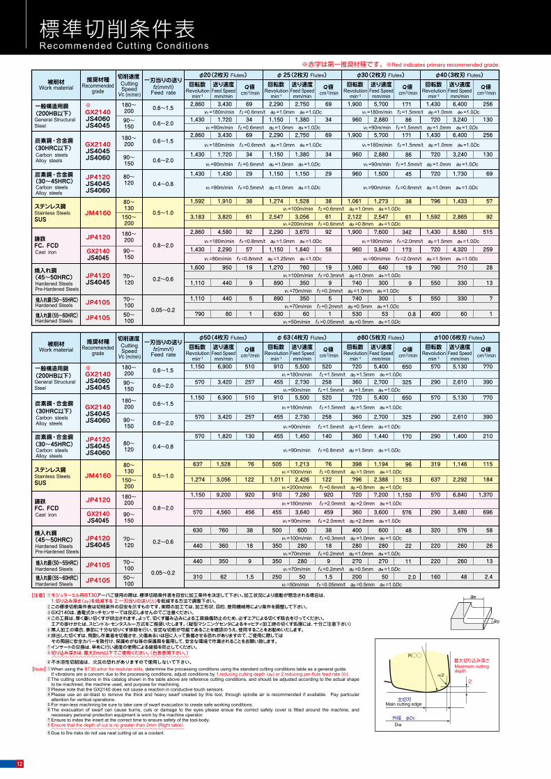
Work : Pre-harden Steel (55HRC)被削材:プリハードン鋼(55HRC)
Overhang and Application Area Work : S50C(220HB) 突出し量と切削領域 被削材:S50C(220HB)
0
0.5
1.0
1.2
1.5
1.8
2.0
0 10 20 30切込み幅 ae Width of Cut (mm)
切込
み深
さ a
p
40 50(溝)
φ50被削材:プリハードン鋼(55HRC)Work Pre-Harden Steelsvc : 90m/minf z : 0.3mm/t
ASRL5050突出し量:130mmOverhang
ASRL5050突出し量:180mmOverhang
00.1
0.50.6
0.8
1.0
1.2
1.5
1.8
2.0
0 5 10切込み幅 ae Width of Cut (mm)
切込
み深
さ a
p
15 20(溝)
φ20被削材:プリハードン鋼(55HRC)Work Pre-Harden Steelsvc : 90m/minf z : 0.3mm/t
ASRL0020突出し量:100mmOverhang
ASRS0020突出し量:70mmOverhang
ASRE0020突出し量:130mmOverhang
Dep
th o
f Cut
(mm
)
Dep
th o
f Cut
(mm
)
切込
み深
さ a
p
00 12.5 25 37.5
切込み幅 ae Width of Cut (mm)
切込
み深
さ a
p
50(溝)
1
2
φ50 ASR4050-4(突出し量:200mm)
ASR4050-4(突出し量:300mm)
vc=180m/min(n=1,150min-1)vf=6,900mm/min(fz=1.5mm/t)
vc=110m/min(n=700min-1)vf=4,000mm/min(fz=1.4mm/t)
Dep
th o
f Cut
(mm
)
Overhang OH : 200mm
Overhang OH : 300mm
切込
み深
さ a
p
00 20 40 60
切込み幅 ae Width of Cut (mm)80(溝)
1
2
φ80 ASR5080-5(突出し量:200mm)
ASR5080-5(突出し量:400mm)
vc=180m/min(n=720min-1)vf=5,400mm/min(fz=1.5mm/t)
vc=90m/min(n=360min-1)vf=4,000mm/min(fz=2.2mm/t)
Dep
th o
f Cut
(mm
)
Overhang OH : 200mm
Overhang OH : 400mm
00 10 20 30
切込み幅 ae Width of Cut (mm)
切込
み深
さ a
p
40(溝)
1
2
φ40 ASRS4040(突出し量:70mm)
ASRE4040(突出し量:230mm)
vc=180m/min(n=1,430min-1)vf=6,400mm/min(fz=1.5mm/t)
vc=100m/min(n=800min-1)vf=2,400mm/min(fz=1.5mm/t)
Overhang OH : 70mm
Overhang OH : 230mm
Dep
th o
f Cut
(mm
)
vc=180m/min(n=900min-1)vf=5,400mm/min(fz=1.5mm/t)
vc=90m/min(n=455min-1)vf=2,730mm/min(fz=1.5mm/t)
00
切込み幅 ae Width of Cut (mm)
切込
み深
さ a
p
20 40 60 63(溝)
0.5
1
2
φ63
ASR5063-4(突出し量:350mm)
ASR5063-4(突出し量:200mm)
Overhang OH : 200mm
Overhang OH : 350mm
Dep
th o
f Cut
(mm
)
vc=180m/min(n=2,290min-1)vf=2,750mm/min(fz=0.6mm/t)
vc=90m/min(n=1,146min-1)vf=2,750mm/min(fz=1.2mm/t)
00 5 10
切込み幅 ae Width of Cut (mm)15 20 25(溝)
0.30.5
1
2
φ25
ASRE0025(突出し量:230mm)
ASRS0025(突出し量:70mm)
Overhang OH : 70mm
Dep
th o
f Cut
(mm
)
Overhang OH : 230mm
切込み幅 ae Width of Cut (mm)
vc=180m/min(n=2,860min-1)vf=3,430mm/min(fz=0.6mm/t)
00 5 10
切込
み深
さ a
p
15 20(溝)
0.20.30.5
1
2
ASRS0020(突出し量:70mm)
ASRE0020(突出し量:180mm)
φ20
vc=90m/min(n=1,450min-1)vf=3,000mm/min(fz=1.0mm/t)
Dep
th o
f Cut
(mm
) Overhang OH : 70mm
Overhang OH : 180mm
vc=180m/min(n=1,900min-1)vf=5,700mm/min(fz=1.5mm/t)
vc=100m/min(n=1,064min-1)vf=4,000mm/min(fz=1.9mm/t)
00 10 20
切込み幅 ae Width of Cut (mm)
切込
み深
さ a
p
30(溝)
1
2
φ30 ASRS4030(突出し量:70mm)
ASRE4030(突出し量:230mm)
Dep
th o
f Cut
(mm
) Overhang OH : 70mm
Overhang OH : 230mm
Full
Full Full
Full
Full
Full Full
Full
Full
標準切削条件表Recommended Cut t ing Condi t ions
最大切り込み深さ
外径 φDc
主切刃
rε2
R
Maximum cutting depth
Main cutting edge
Dia
2
①When using the BT30 arbor for modular mills, determine the processing conditions using the standard cutting conditions table as a general guide. If vibrations are a concern due to the processing conditions, adjust conditions by 1.reducing cutting depth (ap) or 2.reducing per-flute feed rate (fz).②The cutting conditions in this catalog shown in the table above are reference cutting conditions, and should be adjusted according to the actual shape
to be machined, the machine used, and purpose for machining.③Please note that the GX2140 does not cause a reaction in conductive touch sensors.④Please use an air-blast to remove the thick and heavy swarf created by this tool, through spindle air is recommended if available. Pay particular
attention for vertical operations.⑤For man-less machining be sure to take care of swarf evacuation to create safe working conditions.⑥The evacuation of swarf can cause burns, cuts or damage to the eyes please ensue the correct safety cover is fitted around the machine, and
necessary personal protection equipment is worn by the machine operator.⑦Ensure to index the insert at the correct time to ensure safety of the tool-body.⑧Ensure that the depth of cut is no greater than 2mm (Right table).
⑨Due to fire risks do not use neat cutting oil as a coolant.
【Note】
①モジュラーミル用BT30アーバご使用の際は、標準切削条件表を目安に加工条件を決定して下さい。加工状況により振動が懸念される場合は、 1.切り込み深さ(ap)を低減する 2.一刃当りの送り(fz)を低減する方法で調整下さい。②この標準切削条件表は切削条件の目安を示すものです。実際の加工では、加工形状、目的、使用機械等により条件を調整して下さい。③GX2140は、通電式タッチセンサーでは反応しませんのでご注意ください。④この工具は、厚く重い切くずが排出されます。よって、切くず噛み込みによる工具損傷防止のため、必ずエアによる切くず除去を行ってください。 エアの掛けかたは、スピンドル・センタスルー方式をご推奨いたします。(縦型マシニングセンタによるキャビティ加工時の切くず処理には、十分ご注意下さい)⑤無人加工の場合、事前に十分な切りくず排除を行い、安定な切削が可能であることを確認のうえ、使用することをお勧めいたします。⑥排出した切くずは、飛散し作業者を切傷させ、火傷あるいは目に入って負傷させる恐れがありますので、ご使用に際しては その周囲に安全カバーを取付け、保護めがね等の保護具を着用して、安全な環境で作業されることをお願い致します。⑦インサートの交換は、早めに行い過度の使用による破損を防止してください。⑧切り込み深さは、最大2mm以下でご使用ください。(右表参照下さい。)
⑨不水溶性切削油は、火災の恐れがありますので使用しないで下さい。
【注意】
0.2~0.6440
630
360
760
18
38
350
500
280
600
18
38
280
400
280
600
22
48
220
320
260
576
26
58
12070~
Hardened SteelsPre-Hardened Steels
(45~50HRC)焼入れ鋼
0.05~0.2
440 350 9 350 280 9 270 270 11 220 260 13
310 62 1.5 250 50 1.5 200 50 2.0 160 48 2.410070~
10050~
Hardened Steels焼入れ鋼(50~55HRC)
Hardened Steels焼入れ鋼(55~60HRC)
鋳鉄FC, FCD
180~200
90~150
0.8~2.0
4,580
2,290
92
57
2,290
1,150
3,670
1,840
92
58
2,860
1,430
7,600
3,840
342
173
1,430
720
8,580
4,320
515
259
1,900
960Cast iron
0.2~0.61,110
1,600
440
950
9
19
890
1,270
350
760
9
19
740
1,060
300
640
9
19
550
790
330
710
13
28
12070~
Hardened SteelsPre-Hardened Steels
(45~50HRC)焼入れ鋼
0.05~0.2
0.5~1.0
790 80 1 630 60 1 530 53 0.8 400 60
1,110 440 5 890 350 5 740 300 5 550 330 7
1,592 1,910 38 1,274 1,528 38 1,061 1,273 38 796 1,433 57
3,183 3,820 61 2,547 3,056 61 2,122 2,547 61 1,592 2,865 92
637 1,528 76 505 1,213 76 398 1,194 96 319 1,146 115
1,274 3,056 122 1,011 2,426 122 796 2,388 153 637 2,292 184
110050~
10070~
80~130
150~200
0.5~1.0
80~130
150~200
Hardened Steels焼入れ鋼(50~55HRC)
Hardened Steels焼入れ鋼(55~60HRC)
一般構造用鋼(200HB以下)
(30~45HRC)
(30HRC以下)
JP4120
GX2140JS4045
GX2140JS4060JS4045
GX2140JS4045JS4060
JP4120JS4045JS4060
JP4120JS4045
JM4160
JP4105
JP4105
JP4120
GX2140JS4045
GX2140JS4060JS4045
GX2140JS4045JS4060
JP4120JS4045JS4060
JP4120JS4045
JM4160
JP4105
JP4105
General StructuralSteel
一般構造用鋼(200HB以下)General StructuralSteel
180~200
90~150
180~200
90~150
80~120
0.6~1.5
0.6~2.0
0.6~1.5
0.6~2.0
0.4~0.8
3,430
1,720
3,430
1,720
1,430
69
34
69
34
29
2,290
1,150
2,290
1,150
1,150
2,750
1,380
2,750
1,380
1,150
69
34
69
34
29
2,860
1,430
2,860
1,430
1,430
5,700
2,880
5,700
2,880
1,500
171
86
171
86
45
1,430
720
1,430
720
720
6,400
3,240
6,400
3,240
1,730
256
130
256
130
69
1,900
960
1,900
960
960
Carbon steelsAlloy steels
炭素鋼・合金鋼
炭素鋼・合金鋼
Alloy steelsCarbon steels
(30HRC以下)
12080~
15090~
Carbon steelsAlloy steels
Alloy steelsCarbon steels
(30~45HRC)炭素鋼・合金鋼
0.4~0.8
0.6~2.0
200180~
15090~
200180~
炭素鋼・合金鋼
0.6~2.0
0.6~1.5
0.6~1.5
φ 63(4枚刃 Flutes) φ80(5枚刃 Flutes) φ100(6枚刃 Flutes)φ50(4枚刃 Flutes)
1,150
570
1,150
570
570
6,900
3,420
6,900
3,420
1,820
510
257
510
257
130
910
455
910
455
455
5,500
2,730
5,500
2,730
1,450
520
258
520
258
140
720
360
720
360
360
5,400
2,700
5,400
2,700
1,440
650
325
650
325
170
570
290
570
290
290
5,130
2,610
5,130
2,610
1,400
770
390
770
390
210
15090~
200180~
Cast ironFC, FCD鋳鉄
0.8~2.0
1,150
570
9,200
4,560
920
456
910
455
7,280
3,640
920
459
720
360
7,200
3,600
1,150
576
570
290
6,840
3,480
1,370
696
切削速度CuttingSpeed
Vc (m/min)Work material
被削材 推奨材種Recommended
gradefz(mm/t)
Feed rate
一刃当りの送り
切削速度CuttingSpeed
Vc (m/min)Work material
被削材 推奨材種Recommended
gradefz(mm/t)
Feed rate
一刃当りの送り
Revolutionmin-1
回転数Feed Speedmm/min
送り速度 Q値cm3/min Revolution
min-1
回転数Feed Speedmm/min
送り速度 Q値cm3/min Revolution
min-1
回転数Feed Speedmm/min
送り速度 Q値cm3/min Revolution
min-1
回転数Feed Speedmm/min
送り速度 Q値cm3/min
Revolutionmin-1
回転数Feed Speedmm/min
送り速度 Q値cm3/min Revolution
min-1
回転数Feed Speedmm/min
送り速度 Q値cm3/min Revolution
min-1
回転数Feed Speedmm/min
送り速度 Q値cm3/min Revolution
min-1
回転数Feed Speedmm/min
送り速度 Q値cm3/min
φ 25(2枚刃 Flutes) φ30(2枚刃 Flutes) φ40(3枚刃 Flutes)φ20(2枚刃 Flutes)
vc =100m/min fz =0.3mm/t ap =1.0mm ae =1.0Dc
vc =70m/min fz =0.2mm/t ap =1.0mm ae =1.0Dc
vc =70m/min fz =0.2mm/t ap =0.5mm ae =1.0Dc
vc =50m/min fz =0.05mm/t ap =0.5mm ae =1.0Dc
vc =180m/min fz =0.8mm/t ap =1.0mm ae =1.0Dc
vc =90m/min fz =0.8mm/t ap =1.25mm ae =1.0Dc
vc =180m/min fz =2.0mm/t ap =1.5mm ae =1.0Dc
vc =90m/min fz =2.0mm/t ap =1.5mm ae =1.0Dc
vc =100m/min fz =0.3mm/t ap =1.0mm ae =1.0Dc
vc =70m/min fz =0.2mm/t ap =1.0mm ae =1.0Dc
vc =70m/min fz =0.2mm/t ap =0.5mm ae =1.0Dc
vc =50m/min fz =0.05mm/t ap =0.5mm ae =1.0Dc
vc =180m/min fz =0.6mm/t ap =1.0mm ae =1.0Dc
vc =90m/min fz =0.6mm/t ap =1.0mm ae =1.0Dc
vc =180m/min fz =0.6mm/t ap =1.0mm ae =1.0Dc
vc =90m/min fz =0.6mm/t ap =1.0mm ae =1.0Dc
vc =90m/min fz =0.5mm/t ap =1.0mm ae =1.0Dc
vc =180m/min fz =1.5mm/t ap =1.0mm ae =1.0Dc
vc =90m/min fz =1.5mm/t ap =1.0mm ae =1.0Dc
vc =180m/min fz =1.5mm/t ap =1.0mm ae =1.0Dc
vc =90m/min fz =1.5mm/t ap =1.0mm ae =1.0Dc
vc =90m/min fz =0.8mm/t ap =1.0mm ae =1.0Dc
vc =180m/min fz =1.5mm/t ap =1.5mm ae =1.0Dc
vc =90m/min fz =1.5mm/t ap =1.5mm ae =1.0Dc
vc =180m/min fz =1.5mm/t ap =1.5mm ae =1.0Dc
vc =90m/min fz =1.5mm/t ap =1.5mm ae =1.0Dc
vc =90m/min fz =0.8mm/t ap =1.5mm ae =1.0Dc
vc =180m/min fz =2.0mm/t ap =2.0mm ae =1.0Dc
vc =90m/min fz =2.0mm/t ap =2.0mm ae =1.0Dc
vc =100m/min fz =0.6mm/t ap =1.0mm ae =1.0Dc
vc =200m/min fz =0.6mm/t ap =0.8mm ae =1.0Dc
vc =100m/min fz =0.6mm/t ap =1.0mm ae =1.0Dc
vc =200m/min fz =0.6mm/t ap =0.8mm ae =1.0Dc
ステンレス鋼Stainless SteelsSUS
ステンレス鋼Stainless SteelsSUS
※赤字は第一推奨材種です。※Red indicates primary recommended grade.
ae
ap
切削性能 Cutt ing performance
※
※
12

Work : Pre-harden Steel (55HRC)被削材:プリハードン鋼(55HRC)
Overhang and Application Area Work : S50C(220HB) 突出し量と切削領域 被削材:S50C(220HB)
0
0.5
1.0
1.2
1.5
1.8
2.0
0 10 20 30切込み幅 ae Width of Cut (mm)
切込
み深
さ a
p
40 50(溝)
φ50被削材:プリハードン鋼(55HRC)Work Pre-Harden Steelsvc : 90m/minf z : 0.3mm/t
ASRL5050突出し量:130mmOverhang
ASRL5050突出し量:180mmOverhang
00.1
0.50.6
0.8
1.0
1.2
1.5
1.8
2.0
0 5 10切込み幅 ae Width of Cut (mm)
切込
み深
さ a
p
15 20(溝)
φ20被削材:プリハードン鋼(55HRC)Work Pre-Harden Steelsvc : 90m/minf z : 0.3mm/t
ASRL0020突出し量:100mmOverhang
ASRS0020突出し量:70mmOverhang
ASRE0020突出し量:130mmOverhang
Dep
th o
f Cut
(mm
)
Dep
th o
f Cut
(mm
)
切込
み深
さ a
p
00 12.5 25 37.5
切込み幅 ae Width of Cut (mm)
切込
み深
さ a
p
50(溝)
1
2
φ50 ASR4050-4(突出し量:200mm)
ASR4050-4(突出し量:300mm)
vc=180m/min(n=1,150min-1)vf=6,900mm/min(fz=1.5mm/t)
vc=110m/min(n=700min-1)vf=4,000mm/min(fz=1.4mm/t)
Dep
th o
f Cut
(mm
)
Overhang OH : 200mm
Overhang OH : 300mm
切込
み深
さ a
p
00 20 40 60
切込み幅 ae Width of Cut (mm)80(溝)
1
2
φ80 ASR5080-5(突出し量:200mm)
ASR5080-5(突出し量:400mm)
vc=180m/min(n=720min-1)vf=5,400mm/min(fz=1.5mm/t)
vc=90m/min(n=360min-1)vf=4,000mm/min(fz=2.2mm/t)
Dep
th o
f Cut
(mm
)
Overhang OH : 200mm
Overhang OH : 400mm
00 10 20 30
切込み幅 ae Width of Cut (mm)切
込み
深さ
ap
40(溝)
1
2
φ40 ASRS4040(突出し量:70mm)
ASRE4040(突出し量:230mm)
vc=180m/min(n=1,430min-1)vf=6,400mm/min(fz=1.5mm/t)
vc=100m/min(n=800min-1)vf=2,400mm/min(fz=1.5mm/t)
Overhang OH : 70mm
Overhang OH : 230mm
Dep
th o
f Cut
(mm
)vc=180m/min(n=900min-1)vf=5,400mm/min(fz=1.5mm/t)
vc=90m/min(n=455min-1)vf=2,730mm/min(fz=1.5mm/t)
00
切込み幅 ae Width of Cut (mm)
切込
み深
さ a
p
20 40 60 63(溝)
0.5
1
2
φ63
ASR5063-4(突出し量:350mm)
ASR5063-4(突出し量:200mm)
Overhang OH : 200mm
Overhang OH : 350mm
Dep
th o
f Cut
(mm
)
vc=180m/min(n=2,290min-1)vf=2,750mm/min(fz=0.6mm/t)
vc=90m/min(n=1,146min-1)vf=2,750mm/min(fz=1.2mm/t)
00 5 10
切込み幅 ae Width of Cut (mm)15 20 25(溝)
0.30.5
1
2
φ25
ASRE0025(突出し量:230mm)
ASRS0025(突出し量:70mm)
Overhang OH : 70mm
Dep
th o
f Cut
(mm
)
Overhang OH : 230mm
切込み幅 ae Width of Cut (mm)
vc=180m/min(n=2,860min-1)vf=3,430mm/min(fz=0.6mm/t)
00 5 10
切込
み深
さ a
p
15 20(溝)
0.20.30.5
1
2
ASRS0020(突出し量:70mm)
ASRE0020(突出し量:180mm)
φ20
vc=90m/min(n=1,450min-1)vf=3,000mm/min(fz=1.0mm/t)
Dep
th o
f Cut
(mm
) Overhang OH : 70mm
Overhang OH : 180mm
vc=180m/min(n=1,900min-1)vf=5,700mm/min(fz=1.5mm/t)
vc=100m/min(n=1,064min-1)vf=4,000mm/min(fz=1.9mm/t)
00 10 20
切込み幅 ae Width of Cut (mm)
切込
み深
さ a
p
30(溝)
1
2
φ30 ASRS4030(突出し量:70mm)
ASRE4030(突出し量:230mm)
Dep
th o
f Cut
(mm
) Overhang OH : 70mm
Overhang OH : 230mm
Full
Full Full
Full
Full
Full Full
Full
Full
標準切削条件表Recommended Cut t ing Condi t ions
最大切り込み深さ
外径 φDc
主切刃
rε2
R
Maximum cutting depth
Main cutting edge
Dia
2
①When using the BT30 arbor for modular mills, determine the processing conditions using the standard cutting conditions table as a general guide. If vibrations are a concern due to the processing conditions, adjust conditions by 1.reducing cutting depth (ap) or 2.reducing per-flute feed rate (fz).②The cutting conditions in this catalog shown in the table above are reference cutting conditions, and should be adjusted according to the actual shape
to be machined, the machine used, and purpose for machining.③Please note that the GX2140 does not cause a reaction in conductive touch sensors.④Please use an air-blast to remove the thick and heavy swarf created by this tool, through spindle air is recommended if available. Pay particular
attention for vertical operations.⑤For man-less machining be sure to take care of swarf evacuation to create safe working conditions.⑥The evacuation of swarf can cause burns, cuts or damage to the eyes please ensue the correct safety cover is fitted around the machine, and
necessary personal protection equipment is worn by the machine operator.⑦Ensure to index the insert at the correct time to ensure safety of the tool-body.⑧Ensure that the depth of cut is no greater than 2mm (Right table).
⑨Due to fire risks do not use neat cutting oil as a coolant.
【Note】
①モジュラーミル用BT30アーバご使用の際は、標準切削条件表を目安に加工条件を決定して下さい。加工状況により振動が懸念される場合は、 1.切り込み深さ(ap)を低減する 2.一刃当りの送り(fz)を低減する方法で調整下さい。②この標準切削条件表は切削条件の目安を示すものです。実際の加工では、加工形状、目的、使用機械等により条件を調整して下さい。③GX2140は、通電式タッチセンサーでは反応しませんのでご注意ください。④この工具は、厚く重い切くずが排出されます。よって、切くず噛み込みによる工具損傷防止のため、必ずエアによる切くず除去を行ってください。 エアの掛けかたは、スピンドル・センタスルー方式をご推奨いたします。(縦型マシニングセンタによるキャビティ加工時の切くず処理には、十分ご注意下さい)⑤無人加工の場合、事前に十分な切りくず排除を行い、安定な切削が可能であることを確認のうえ、使用することをお勧めいたします。⑥排出した切くずは、飛散し作業者を切傷させ、火傷あるいは目に入って負傷させる恐れがありますので、ご使用に際しては その周囲に安全カバーを取付け、保護めがね等の保護具を着用して、安全な環境で作業されることをお願い致します。⑦インサートの交換は、早めに行い過度の使用による破損を防止してください。⑧切り込み深さは、最大2mm以下でご使用ください。(右表参照下さい。)
⑨不水溶性切削油は、火災の恐れがありますので使用しないで下さい。
【注意】
0.2~0.6440
630
360
760
18
38
350
500
280
600
18
38
280
400
280
600
22
48
220
320
260
576
26
58
12070~
Hardened SteelsPre-Hardened Steels
(45~50HRC)焼入れ鋼
0.05~0.2
440 350 9 350 280 9 270 270 11 220 260 13
310 62 1.5 250 50 1.5 200 50 2.0 160 48 2.410070~
10050~
Hardened Steels焼入れ鋼(50~55HRC)
Hardened Steels焼入れ鋼(55~60HRC)
鋳鉄FC, FCD
180~200
90~150
0.8~2.0
4,580
2,290
92
57
2,290
1,150
3,670
1,840
92
58
2,860
1,430
7,600
3,840
342
173
1,430
720
8,580
4,320
515
259
1,900
960Cast iron
0.2~0.61,110
1,600
440
950
9
19
890
1,270
350
760
9
19
740
1,060
300
640
9
19
550
790
330
710
13
28
12070~
Hardened SteelsPre-Hardened Steels
(45~50HRC)焼入れ鋼
0.05~0.2
0.5~1.0
790 80 1 630 60 1 530 53 0.8 400 60
1,110 440 5 890 350 5 740 300 5 550 330 7
1,592 1,910 38 1,274 1,528 38 1,061 1,273 38 796 1,433 57
3,183 3,820 61 2,547 3,056 61 2,122 2,547 61 1,592 2,865 92
637 1,528 76 505 1,213 76 398 1,194 96 319 1,146 115
1,274 3,056 122 1,011 2,426 122 796 2,388 153 637 2,292 184
110050~
10070~
80~130
150~200
0.5~1.0
80~130
150~200
Hardened Steels焼入れ鋼(50~55HRC)
Hardened Steels焼入れ鋼(55~60HRC)
一般構造用鋼(200HB以下)
(30~45HRC)
(30HRC以下)
JP4120
GX2140JS4045
GX2140JS4060JS4045
GX2140JS4045JS4060
JP4120JS4045JS4060
JP4120JS4045
JM4160
JP4105
JP4105
JP4120
GX2140JS4045
GX2140JS4060JS4045
GX2140JS4045JS4060
JP4120JS4045JS4060
JP4120JS4045
JM4160
JP4105
JP4105
General StructuralSteel
一般構造用鋼(200HB以下)General StructuralSteel
180~200
90~150
180~200
90~150
80~120
0.6~1.5
0.6~2.0
0.6~1.5
0.6~2.0
0.4~0.8
3,430
1,720
3,430
1,720
1,430
69
34
69
34
29
2,290
1,150
2,290
1,150
1,150
2,750
1,380
2,750
1,380
1,150
69
34
69
34
29
2,860
1,430
2,860
1,430
1,430
5,700
2,880
5,700
2,880
1,500
171
86
171
86
45
1,430
720
1,430
720
720
6,400
3,240
6,400
3,240
1,730
256
130
256
130
69
1,900
960
1,900
960
960
Carbon steelsAlloy steels
炭素鋼・合金鋼
炭素鋼・合金鋼
Alloy steelsCarbon steels
(30HRC以下)
12080~
15090~
Carbon steelsAlloy steels
Alloy steelsCarbon steels
(30~45HRC)炭素鋼・合金鋼
0.4~0.8
0.6~2.0
200180~
15090~
200180~
炭素鋼・合金鋼
0.6~2.0
0.6~1.5
0.6~1.5
φ 63(4枚刃 Flutes) φ80(5枚刃 Flutes) φ100(6枚刃 Flutes)φ50(4枚刃 Flutes)
1,150
570
1,150
570
570
6,900
3,420
6,900
3,420
1,820
510
257
510
257
130
910
455
910
455
455
5,500
2,730
5,500
2,730
1,450
520
258
520
258
140
720
360
720
360
360
5,400
2,700
5,400
2,700
1,440
650
325
650
325
170
570
290
570
290
290
5,130
2,610
5,130
2,610
1,400
770
390
770
390
210
15090~
200180~
Cast ironFC, FCD鋳鉄
0.8~2.0
1,150
570
9,200
4,560
920
456
910
455
7,280
3,640
920
459
720
360
7,200
3,600
1,150
576
570
290
6,840
3,480
1,370
696
切削速度CuttingSpeed
Vc (m/min)Work material
被削材 推奨材種Recommended
gradefz(mm/t)
Feed rate
一刃当りの送り
切削速度CuttingSpeed
Vc (m/min)Work material
被削材 推奨材種Recommended
gradefz(mm/t)
Feed rate
一刃当りの送り
Revolutionmin-1
回転数Feed Speedmm/min
送り速度 Q値cm3/min Revolution
min-1
回転数Feed Speedmm/min
送り速度 Q値cm3/min Revolution
min-1
回転数Feed Speedmm/min
送り速度 Q値cm3/min Revolution
min-1
回転数Feed Speedmm/min
送り速度 Q値cm3/min
Revolutionmin-1
回転数Feed Speedmm/min
送り速度 Q値cm3/min Revolution
min-1
回転数Feed Speedmm/min
送り速度 Q値cm3/min Revolution
min-1
回転数Feed Speedmm/min
送り速度 Q値cm3/min Revolution
min-1
回転数Feed Speedmm/min
送り速度 Q値cm3/min
φ 25(2枚刃 Flutes) φ30(2枚刃 Flutes) φ40(3枚刃 Flutes)φ20(2枚刃 Flutes)
vc =100m/min fz =0.3mm/t ap =1.0mm ae =1.0Dc
vc =70m/min fz =0.2mm/t ap =1.0mm ae =1.0Dc
vc =70m/min fz =0.2mm/t ap =0.5mm ae =1.0Dc
vc =50m/min fz =0.05mm/t ap =0.5mm ae =1.0Dc
vc =180m/min fz =0.8mm/t ap =1.0mm ae =1.0Dc
vc =90m/min fz =0.8mm/t ap =1.25mm ae =1.0Dc
vc =180m/min fz =2.0mm/t ap =1.5mm ae =1.0Dc
vc =90m/min fz =2.0mm/t ap =1.5mm ae =1.0Dc
vc =100m/min fz =0.3mm/t ap =1.0mm ae =1.0Dc
vc =70m/min fz =0.2mm/t ap =1.0mm ae =1.0Dc
vc =70m/min fz =0.2mm/t ap =0.5mm ae =1.0Dc
vc =50m/min fz =0.05mm/t ap =0.5mm ae =1.0Dc
vc =180m/min fz =0.6mm/t ap =1.0mm ae =1.0Dc
vc =90m/min fz =0.6mm/t ap =1.0mm ae =1.0Dc
vc =180m/min fz =0.6mm/t ap =1.0mm ae =1.0Dc
vc =90m/min fz =0.6mm/t ap =1.0mm ae =1.0Dc
vc =90m/min fz =0.5mm/t ap =1.0mm ae =1.0Dc
vc =180m/min fz =1.5mm/t ap =1.0mm ae =1.0Dc
vc =90m/min fz =1.5mm/t ap =1.0mm ae =1.0Dc
vc =180m/min fz =1.5mm/t ap =1.0mm ae =1.0Dc
vc =90m/min fz =1.5mm/t ap =1.0mm ae =1.0Dc
vc =90m/min fz =0.8mm/t ap =1.0mm ae =1.0Dc
vc =180m/min fz =1.5mm/t ap =1.5mm ae =1.0Dc
vc =90m/min fz =1.5mm/t ap =1.5mm ae =1.0Dc
vc =180m/min fz =1.5mm/t ap =1.5mm ae =1.0Dc
vc =90m/min fz =1.5mm/t ap =1.5mm ae =1.0Dc
vc =90m/min fz =0.8mm/t ap =1.5mm ae =1.0Dc
vc =180m/min fz =2.0mm/t ap =2.0mm ae =1.0Dc
vc =90m/min fz =2.0mm/t ap =2.0mm ae =1.0Dc
vc =100m/min fz =0.6mm/t ap =1.0mm ae =1.0Dc
vc =200m/min fz =0.6mm/t ap =0.8mm ae =1.0Dc
vc =100m/min fz =0.6mm/t ap =1.0mm ae =1.0Dc
vc =200m/min fz =0.6mm/t ap =0.8mm ae =1.0Dc
ステンレス鋼Stainless SteelsSUS
ステンレス鋼Stainless SteelsSUS
※赤字は第一推奨材種です。※Red indicates primary recommended grade.
ae
ap
切削性能 Cutt ing performance
※
※
13
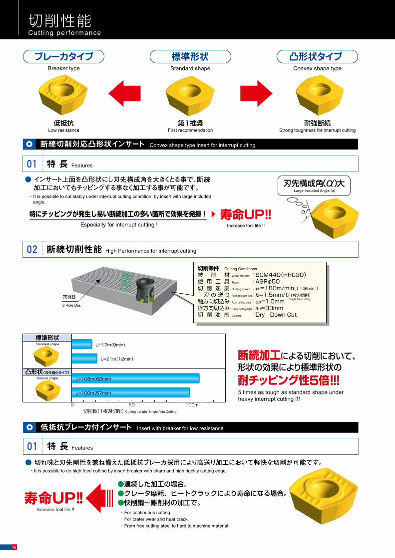
Especially for interrupt cutting !
Breaker type Standard shape Convex shape type
Standard shape
Convex shape
5 times as tough as standard shape under heavy interrupt cutting !!!
特にチッピングが発生し易い断続加工の多い箇所で効果を発揮!
標準形状
凸形状(刃先強化タイプ)
断続加工による切削において、形状の効果により標準形状の耐チッピング性5倍!!!
低抵抗Low resistance
第1推奨First recommendation
耐強断続Strong toughness for interrupt cutting
標準形状 凸形状タイプブレーカタイプ
寿命UP!!
L=17m(9min)
L=21m(12min)
L=100m(57min)
L=108m(62min)
500 100m切削長(1枚刃切削) Cutting Length(Single flute Cutting)
Increase tool life !!
刃先構成角(α)大Large Included Angle (α)
α
8 Hole Dia.
穴径8
切削条件 Cutting Conditions
被 削 材 Work material : SCM440(HRC30)使 用 工 具 Tools : ASRφ50切 削 速 度 Cutting speed : vc=180m/min(1,146min-1)1 刃 の 送 り Feed rate per flute : fz=1.5mm/t(1枚刃切削)軸方向切込み Axial cutting depth : ap=1.0mm径方向切込み Radial cutting depth : ae=33mm切 削 油 剤 Coolant : Dry Down-Cut
Single flute cutting
断続切削対応凸形状インサート Convex shape type insert for interrupt cutting
特 長 Features01
断続切削性能 High Performance for interrupt cutting02
● インサート上面を凸形状にし刃先構成角を大きくとる事で、断続加工においてもチッピングする事なく加工する事が可能です。
・It is possible to cut stably under interrupt cutting condition by insert with large included angle.
アルファ 高送りラジアスミルASR形は、高送り切削による高能率加工をご提案致します。Introducing the Super Radius Mill ASR. High-feed, high-efficiency processing capability is in your hands.
1刃当りの送り量 fz Feed rate(mm/t)
切削
速度
Vc
Cut
ting
spee
d(m
/min
) 高能率加工ご提案条件Proposal for high-efficiency processing
アルファ 高送りラジアスミルによる加工条件
Cutting conditions by ASR
100
1,000
4050
200
300400500
1
10
0 0.5 1 1.5 2 2.5 3 3.5
現 在Conventional
1,617N(165kgf)
3,067N(313kgf)
1,764N(180kgf)
3,891N(397kgf)
10%DOWN
ブレーカ付 With breaker
標準形状 Standard shape X(送り分力)
Y(主分力)
Z(背分力)
合力
X:Radial force
Y:Principal force
Z:Back force
Resultant force
X(送り分力)
Y(主分力)
Z(背分力)
合力
X:Radial force
Y:Principal force
Z:Back force
Resultant force
1,548N(158kgf)
2,744N(280kgf)
3,479N(355kgf)
1,470N(150kgf)
切 削 条 件 Cutting Conditions
被 削 材 Work material : S50C(220HB)使 用 工 具 Tools : ASRφ60切 削 速 度 Cutting speed : vc=150m/min(796min-1)
1 刃 の 送 り Feed rate per flute : fz=1.0mm/t(1枚刃切削)
軸方向切込み Axial cutting depth : ap=1.5mm径方向切込み Radial cutting depth : ae=40mm切 削 油 剤 Coolant : Dry Down-Cut
Single flute cutting
切削抵抗(3分力) Cutting force (three forces)02
実績は語る(ユーザーテスト結果) Field Data (User Test Results)03
寿命UP!!●連続した加工の場合。●クレータ摩耗、ヒートクラックにより寿命になる場合。●快削鋼~難削材の加工で。
Increase tool life !! ・For continuous cutting.・For crater wear and heat crack.・From free cutting steel to hard to machine material.
低抵抗ブレーカ付インサート Insert with breaker for low resistance
特 長 Features01● 切れ味と刃先剛性を兼ね備えた低抵抗ブレーカ採用により高送り加工において軽快な切削が可能です。
・It is possible to do high feed cutting by insert breaker with sharp and high rigidity cutting edge.
No
1
2
3
4
6
7
50
63
80
K社Company K
W社Company W
T社Company T
R社Company R
T社Company T
F社Company F
インサート材質 Insert grade
インサート形番Insert item code
被削材Work
material
FCD450凸形状 Convex shape
EDNW15T4TN-15Z
ブレーカ Breaker
EDMT15T4TN-15
凸形状 Convex shape
EDNW15T4TN-15Z
標準形状 Standard shape
EDNW15T4TN-15
標準形状 Standard shape
EDNW15T4TN-15
凸形状 Convex shape
EDNW15T4TN-15Z
12Cr材12 Cr material
P20
P21(40HRC)
S55C
SKD11(30HRC)
使用条件 Cutting conditions
vc m/minn(min-1)
結 果Result
5 R社Company R
標準形状 Standard shape
EDEW15T4TN-15SKD61
(47HRC)
188(1,200)
90(455)
90(455)
97(490)
140(560)
100(400)
120(606)
7,000(1.94)
1,100(0.6)
4,000(2.22)
1,060(0.54)
3,200(1.14)
3,600(1.8)
364(0.15)
1.5×35
ap=1.5
ap=1
ap=1
ap=1
1.0×40
ap=1
ap×aemm
vf mm/minfz(mm/t)
従来品は4時間で欠損。凸形状インサートは正常摩耗。A conventional product was chipped after 4 hours.The convex shaped insert wore normally.
ブレーカの効果により抵抗小さく切削性良好。Breaker effect reduced resistance to provide good cutting.
従来品の寿命2倍以上。Tool life was more than 2 times as long.
従来品の寿命1.5倍。Tool life was 1.5 times as long.
9時間加工。S社の4.5倍の寿命達成。9 hours of machining. Achieved 4.5 times the tool life of a Company S product.
4時間加工しVBmax=0.16mm。継続使用可能。After 4 hours of machining, VBmax was 0.16mm. Can be used for intermittent machining.
従来品はピン穴部で欠損。凸形状インサートはvf=3,600mm/minで安定加工。A conventional product was chipped at the pin hole section. The convex shaped insert provided stable machining at vf=3,600mm/min.
カッタ径DcDiameter
mm
ユーザー名User
切削性能 Cutt ing performance
14
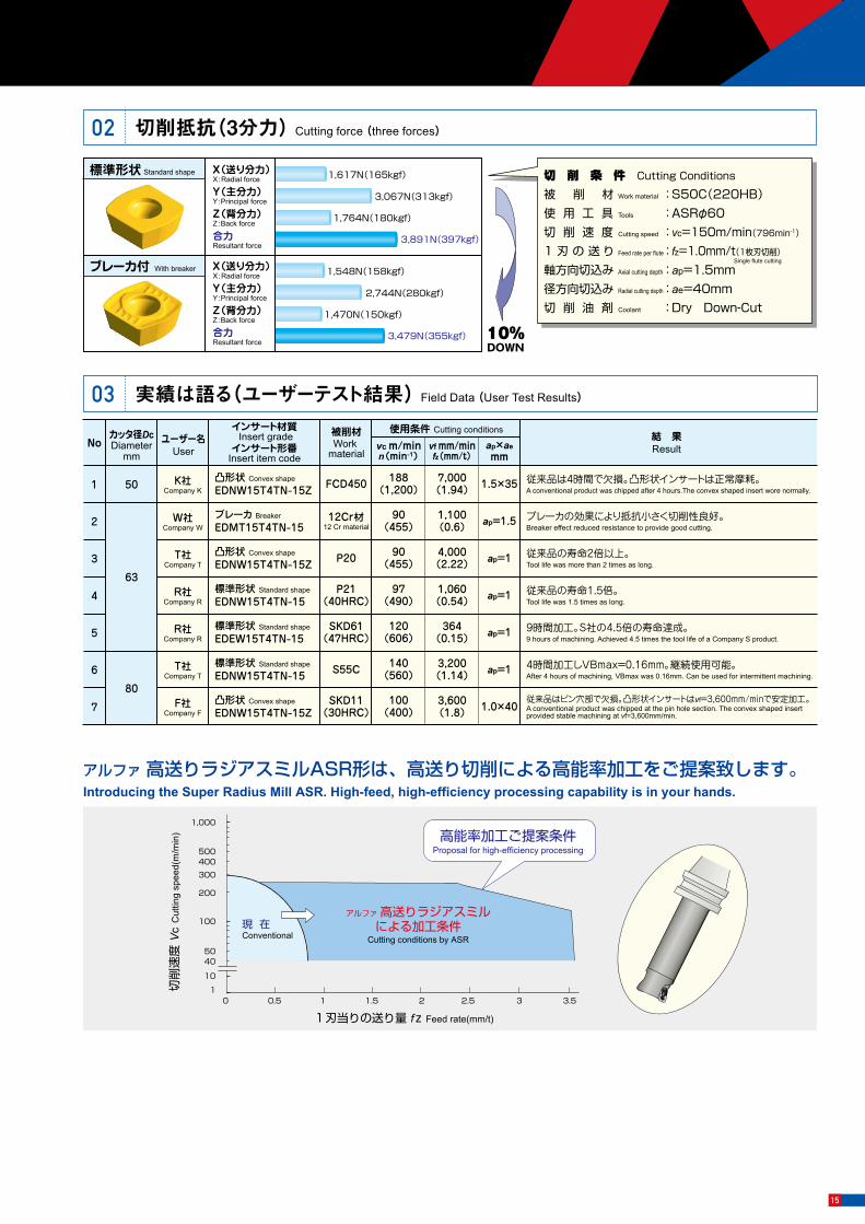
Especially for interrupt cutting !
Breaker type Standard shape Convex shape type
Standard shape
Convex shape
5 times as tough as standard shape under heavy interrupt cutting !!!
特にチッピングが発生し易い断続加工の多い箇所で効果を発揮!
標準形状
凸形状(刃先強化タイプ)
断続加工による切削において、形状の効果により標準形状の耐チッピング性5倍!!!
低抵抗Low resistance
第1推奨First recommendation
耐強断続Strong toughness for interrupt cutting
標準形状 凸形状タイプブレーカタイプ
寿命UP!!
L=17m(9min)
L=21m(12min)
L=100m(57min)
L=108m(62min)
500 100m切削長(1枚刃切削) Cutting Length(Single flute Cutting)
Increase tool life !!
刃先構成角(α)大Large Included Angle (α)
α
8 Hole Dia.
穴径8
切削条件 Cutting Conditions
被 削 材 Work material : SCM440(HRC30)使 用 工 具 Tools : ASRφ50切 削 速 度 Cutting speed : vc=180m/min(1,146min-1)1 刃 の 送 り Feed rate per flute : fz=1.5mm/t(1枚刃切削)軸方向切込み Axial cutting depth : ap=1.0mm径方向切込み Radial cutting depth : ae=33mm切 削 油 剤 Coolant : Dry Down-Cut
Single flute cutting
断続切削対応凸形状インサート Convex shape type insert for interrupt cutting
特 長 Features01
断続切削性能 High Performance for interrupt cutting02
● インサート上面を凸形状にし刃先構成角を大きくとる事で、断続加工においてもチッピングする事なく加工する事が可能です。
・It is possible to cut stably under interrupt cutting condition by insert with large included angle.
アルファ 高送りラジアスミルASR形は、高送り切削による高能率加工をご提案致します。Introducing the Super Radius Mill ASR. High-feed, high-efficiency processing capability is in your hands.
1刃当りの送り量 fz Feed rate(mm/t)
切削
速度
Vc
Cut
ting
spee
d(m
/min
) 高能率加工ご提案条件Proposal for high-efficiency processing
アルファ 高送りラジアスミルによる加工条件
Cutting conditions by ASR
100
1,000
4050
200
300400500
1
10
0 0.5 1 1.5 2 2.5 3 3.5
現 在Conventional
1,617N(165kgf)
3,067N(313kgf)
1,764N(180kgf)
3,891N(397kgf)
10%DOWN
ブレーカ付 With breaker
標準形状 Standard shape X(送り分力)
Y(主分力)
Z(背分力)
合力
X:Radial force
Y:Principal force
Z:Back force
Resultant force
X(送り分力)
Y(主分力)
Z(背分力)
合力
X:Radial force
Y:Principal force
Z:Back force
Resultant force
1,548N(158kgf)
2,744N(280kgf)
3,479N(355kgf)
1,470N(150kgf)
切 削 条 件 Cutting Conditions
被 削 材 Work material : S50C(220HB)使 用 工 具 Tools : ASRφ60切 削 速 度 Cutting speed : vc=150m/min(796min-1)
1 刃 の 送 り Feed rate per flute : fz=1.0mm/t(1枚刃切削)
軸方向切込み Axial cutting depth : ap=1.5mm径方向切込み Radial cutting depth : ae=40mm切 削 油 剤 Coolant : Dry Down-Cut
Single flute cutting
切削抵抗(3分力) Cutting force (three forces)02
実績は語る(ユーザーテスト結果) Field Data (User Test Results)03
寿命UP!!●連続した加工の場合。●クレータ摩耗、ヒートクラックにより寿命になる場合。●快削鋼~難削材の加工で。
Increase tool life !! ・For continuous cutting.・For crater wear and heat crack.・From free cutting steel to hard to machine material.
低抵抗ブレーカ付インサート Insert with breaker for low resistance
特 長 Features01● 切れ味と刃先剛性を兼ね備えた低抵抗ブレーカ採用により高送り加工において軽快な切削が可能です。
・It is possible to do high feed cutting by insert breaker with sharp and high rigidity cutting edge.
No
1
2
3
4
6
7
50
63
80
K社Company K
W社Company W
T社Company T
R社Company R
T社Company T
F社Company F
インサート材質 Insert grade
インサート形番Insert item code
被削材Work
material
FCD450凸形状 Convex shape
EDNW15T4TN-15Z
ブレーカ Breaker
EDMT15T4TN-15
凸形状 Convex shape
EDNW15T4TN-15Z
標準形状 Standard shape
EDNW15T4TN-15
標準形状 Standard shape
EDNW15T4TN-15
凸形状 Convex shape
EDNW15T4TN-15Z
12Cr材12 Cr material
P20
P21(40HRC)
S55C
SKD11(30HRC)
使用条件 Cutting conditions
vc m/minn(min-1)
結 果Result
5 R社Company R
標準形状 Standard shape
EDEW15T4TN-15SKD61
(47HRC)
188(1,200)
90(455)
90(455)
97(490)
140(560)
100(400)
120(606)
7,000(1.94)
1,100(0.6)
4,000(2.22)
1,060(0.54)
3,200(1.14)
3,600(1.8)
364(0.15)
1.5×35
ap=1.5
ap=1
ap=1
ap=1
1.0×40
ap=1
ap×aemm
vf mm/minfz(mm/t)
従来品は4時間で欠損。凸形状インサートは正常摩耗。A conventional product was chipped after 4 hours.The convex shaped insert wore normally.
ブレーカの効果により抵抗小さく切削性良好。Breaker effect reduced resistance to provide good cutting.
従来品の寿命2倍以上。Tool life was more than 2 times as long.
従来品の寿命1.5倍。Tool life was 1.5 times as long.
9時間加工。S社の4.5倍の寿命達成。9 hours of machining. Achieved 4.5 times the tool life of a Company S product.
4時間加工しVBmax=0.16mm。継続使用可能。After 4 hours of machining, VBmax was 0.16mm. Can be used for intermittent machining.
従来品はピン穴部で欠損。凸形状インサートはvf=3,600mm/minで安定加工。A conventional product was chipped at the pin hole section. The convex shaped insert provided stable machining at vf=3,600mm/min.
カッタ径DcDiameter
mm
ユーザー名User
切削性能 Cutt ing performance
15
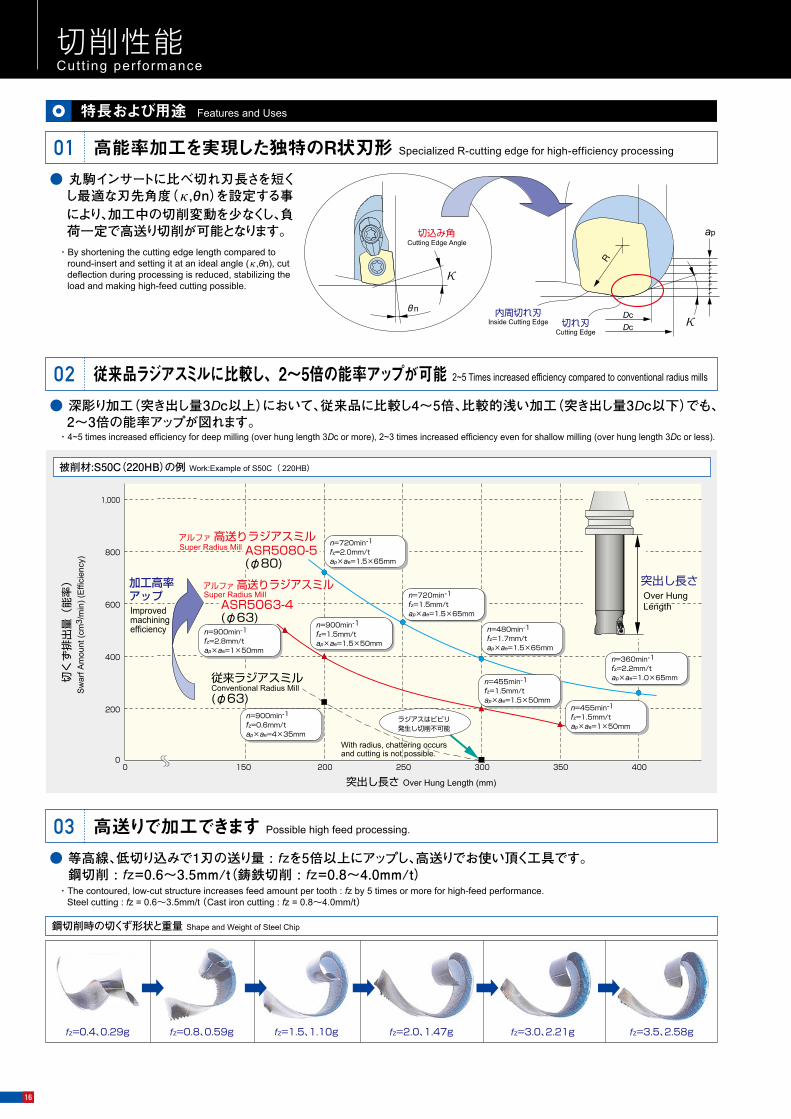
切削性能 Cutt ing performance
切 削 条 件 Cutting Conditions
アルファ 高送りラジアスミルφ80×5枚刃Super Radius Mill φ80×5 flutes(ASR5080-5)Vc=180m/min(n=720min-1)Vf=1,500mm/minfz=0.42mm/tap×ae=1.5×60mmダウンカット、ドライ切削 X⊕
Y⊕
Z⊕(背分力)radial force
down cut, dry cutting
外径Dc Tool diameter.
傾斜角θ Ramp Angle
ヘリカル穴径 Hole Dia.
2°
27~38
2° 3° 2.5° 2° 1.5° 1° 1° 0.5° 0.5°
37~48 38~58 42~62 58~78 78~98 98~118 101~124 136~158 176~198
φ20 φ25 φ30 φ32 φ40 φ50 φ60 φ63 φ80 φ100(mm)
傾斜切削 Ramping
傾斜角θ Ramp Angle
ヘリカル切削 Helical milling
ヘリカル穴径Hole Dia.
100100
200
200
X
Y
Z
1,980N(202kgf)
3,489N(356kgf)
100
1,196N(122kgf) 55.4°
2,617N(267kgf)
多くの切くず排出が可能 Efficient chip removal04● ご使用される加工機械やツールパスが適合すれば、単位時間当りの切くず排出量は、工具刃径φ63以上では鋼切
削で600cm³/min以上、鋳鉄切削で1,000cm³/min以上も可能です。・With compatible processing machinery and tool path, chip removal per time unit can be as much as 600cm3/min or more for steel milling, and 1,000cm3/min
or more for cast iron milling when cutting Dia. of φ63 or more is used.
ダイレクトに彫り込み加工も可能 Processing by direct milling possible06● 中心まで切れ刃がないため傾斜角度は制限されますが、下図に示しますように傾斜切削やヘリカル切削にて、下穴が
なくてもダイレクトに彫り込み加工が可能です。・Although Ramp angle is limited due to cutting edge design, direct milling is possible without pre-cutting with Ramping and helical milling methods like next pictures.
工具突出し長さが大きくても、たわみの生じにくい刃形 Bend-proof blade shape even with long over hung length05● 単なる横送り(XY平面)加工で、傾斜やヘリカル切削と同レベルの背分力が働き、たわみにくい刃形になっています。
・With horizontal (XY plane) processing, radial force is kept at a level equal to that of slant milling and helical milling, for a bend- proof blade performance.
3分力切削抵抗測定例 Measurement example for 3 force components of cutting resistance
【注意】 ①傾斜角θは上記範囲を超えない様に設定して下さい。0.5°以下での使用を推奨します。②穴径が上記範囲以下の場合は下穴をあけて加工してください。【Note】①The ramp angle θ should be set within the ranges listed above. Use at ramp angles of 0.5。 or less is recommended. ②For hole diameters outside the ranges listed above, a pilot hole should be drilled before milling.
内周切れ刃Inside Cutting Edge 切れ刃
Cutting Edge
切込み角Cutting Edge Angle
ap
DcDc κ
κ
θn
R
特長および用途 Features and Uses
高能率加工を実現した独特のR状刃形 Specialized R-cutting edge for high-efficiency processing01● 丸駒インサートに比べ切れ刃長さを短く
し最適な刃先角度(κ,θn)を設定する事により、加工中の切削変動を少なくし、負荷一定で高送り切削が可能となります。
・By shortening the cutting edge length compared to round-insert and setting it at an ideal angle (κ,θn), cut deflection during processing is reduced, stabilizing the load and making high-feed cutting possible.
従来品ラジアスミルに比較し、2~5倍の能率アップが可能 2~5 Times increased efficiency compared to conventional radius mills02● 深彫り加工(突き出し量3Dc以上)において、従来品に比較し4~5倍、比較的浅い加工(突き出し量3Dc以下)でも、
2~3倍の能率アップが図れます。・4~5 times increased efficiency for deep milling (over hung length 3Dc or more), 2~3 times increased efficiency even for shallow milling (over hung length 3Dc or less).
200
400
600
800
1,000
2001500 250 300 350 4000
n=900min-1
fz=0.6mm/tap×ae=4×35mm
ASR5063-4(φ63)
n=900min-1fz=1.5mm/tap×ae=1.5×50mm
n=455min-1
fz=1.5mm/tap×ae=1×50mm
n=720min-1
fz=2.0mm/tap×ae=1.5×65mm(φ80)
n=720min-1
fz=1.5mm/tap×ae=1.5×65mm
n=480min-1
fz=1.7mm/tap×ae=1.5×65mm
n=360min-1
fz=2.2mm/tap×ae=1.0×65mm
突出し長さ Over Hung Length (mm)
n=900min-1
fz=2.8mm/tap×ae=1×50mm
n=455min-1
fz=1.5mm/tap×ae=1.5×50mm
従来ラジアスミル
(φ63)
アルファ 高送りラジアスミル
アルファ 高送りラジアスミル加工高率アップ
ASR5080-5
Sw
arf A
mou
nt (c
m3 /
min
) (E
ffici
ency
)
突出し長さOver Hung Length
切く
ず排
出量
(能
率)
ラジアスはビビリ発生し切削不可能
Improved machining efficiency
Super Radius Mill
Super Radius Mill
Conventional Radius Mill
With radius, chattering occurs and cutting is not possible.With radius, chattering occurs and cutting is not possible.
被削材:S50C(220HB)の例 Work:Example of S50C( 220HB)
fz=0.4、0.29g fz=0.8、0.59g fz=1.5、1.10g fz=2.0、1.47g fz=3.0、2.21g fz=3.5、2.58g
高送りで加工できます Possible high feed processing.03● 等高線、低切り込みで1刃の送り量 : fzを5倍以上にアップし、高送りでお使い頂く工具です。
鋼切削 : fz=0.6~3.5mm/t(鋳鉄切削 : fz=0.8~4.0mm/t)・The contoured, low-cut structure increases feed amount per tooth : fz by 5 times or more for high-feed performance.
Steel cutting : fz = 0.6~3.5mm/t (Cast iron cutting : fz = 0.8~4.0mm/t)
鋼切削時の切くず形状と重量 Shape and Weight of Steel Chip
16

切削性能 Cutt ing performance
切 削 条 件 Cutting Conditions
アルファ 高送りラジアスミルφ80×5枚刃Super Radius Mill φ80×5 flutes(ASR5080-5)Vc=180m/min(n=720min-1)Vf=1,500mm/minfz=0.42mm/tap×ae=1.5×60mmダウンカット、ドライ切削 X⊕
Y⊕
Z⊕(背分力)radial force
down cut, dry cutting
外径Dc Tool diameter.
傾斜角θ Ramp Angle
ヘリカル穴径 Hole Dia.
2°
27~38
2° 3° 2.5° 2° 1.5° 1° 1° 0.5° 0.5°
37~48 38~58 42~62 58~78 78~98 98~118 101~124 136~158 176~198
φ20 φ25 φ30 φ32 φ40 φ50 φ60 φ63 φ80 φ100(mm)
傾斜切削 Ramping
傾斜角θ Ramp Angle
ヘリカル切削 Helical milling
ヘリカル穴径Hole Dia.
100100
200
200
X
Y
Z
1,980N(202kgf)
3,489N(356kgf)
100
1,196N(122kgf) 55.4°
2,617N(267kgf)
多くの切くず排出が可能 Efficient chip removal04● ご使用される加工機械やツールパスが適合すれば、単位時間当りの切くず排出量は、工具刃径φ63以上では鋼切
削で600cm³/min以上、鋳鉄切削で1,000cm³/min以上も可能です。・With compatible processing machinery and tool path, chip removal per time unit can be as much as 600cm3/min or more for steel milling, and 1,000cm3/min
or more for cast iron milling when cutting Dia. of φ63 or more is used.
ダイレクトに彫り込み加工も可能 Processing by direct milling possible06● 中心まで切れ刃がないため傾斜角度は制限されますが、下図に示しますように傾斜切削やヘリカル切削にて、下穴が
なくてもダイレクトに彫り込み加工が可能です。・Although Ramp angle is limited due to cutting edge design, direct milling is possible without pre-cutting with Ramping and helical milling methods like next pictures.
工具突出し長さが大きくても、たわみの生じにくい刃形 Bend-proof blade shape even with long over hung length05● 単なる横送り(XY平面)加工で、傾斜やヘリカル切削と同レベルの背分力が働き、たわみにくい刃形になっています。
・With horizontal (XY plane) processing, radial force is kept at a level equal to that of slant milling and helical milling, for a bend- proof blade performance.
3分力切削抵抗測定例 Measurement example for 3 force components of cutting resistance
【注意】 ①傾斜角θは上記範囲を超えない様に設定して下さい。0.5°以下での使用を推奨します。②穴径が上記範囲以下の場合は下穴をあけて加工してください。【Note】①The ramp angle θ should be set within the ranges listed above. Use at ramp angles of 0.5。 or less is recommended. ②For hole diameters outside the ranges listed above, a pilot hole should be drilled before milling.
内周切れ刃Inside Cutting Edge 切れ刃
Cutting Edge
切込み角Cutting Edge Angle
ap
DcDc κ
κ
θn
R
特長および用途 Features and Uses
高能率加工を実現した独特のR状刃形 Specialized R-cutting edge for high-efficiency processing01● 丸駒インサートに比べ切れ刃長さを短く
し最適な刃先角度(κ,θn)を設定する事により、加工中の切削変動を少なくし、負荷一定で高送り切削が可能となります。
・By shortening the cutting edge length compared to round-insert and setting it at an ideal angle (κ,θn), cut deflection during processing is reduced, stabilizing the load and making high-feed cutting possible.
従来品ラジアスミルに比較し、2~5倍の能率アップが可能 2~5 Times increased efficiency compared to conventional radius mills02● 深彫り加工(突き出し量3Dc以上)において、従来品に比較し4~5倍、比較的浅い加工(突き出し量3Dc以下)でも、
2~3倍の能率アップが図れます。・4~5 times increased efficiency for deep milling (over hung length 3Dc or more), 2~3 times increased efficiency even for shallow milling (over hung length 3Dc or less).
200
400
600
800
1,000
2001500 250 300 350 4000
n=900min-1
fz=0.6mm/tap×ae=4×35mm
ASR5063-4(φ63)
n=900min-1fz=1.5mm/tap×ae=1.5×50mm
n=455min-1
fz=1.5mm/tap×ae=1×50mm
n=720min-1
fz=2.0mm/tap×ae=1.5×65mm(φ80)
n=720min-1
fz=1.5mm/tap×ae=1.5×65mm
n=480min-1
fz=1.7mm/tap×ae=1.5×65mm
n=360min-1
fz=2.2mm/tap×ae=1.0×65mm
突出し長さ Over Hung Length (mm)
n=900min-1
fz=2.8mm/tap×ae=1×50mm
n=455min-1
fz=1.5mm/tap×ae=1.5×50mm
従来ラジアスミル
(φ63)
アルファ 高送りラジアスミル
アルファ 高送りラジアスミル加工高率アップ
ASR5080-5
Sw
arf A
mou
nt (c
m3 /
min
) (E
ffici
ency
)
突出し長さOver Hung Length
切く
ず排
出量
(能
率)
ラジアスはビビリ発生し切削不可能
Improved machining efficiency
Super Radius Mill
Super Radius Mill
Conventional Radius Mill
With radius, chattering occurs and cutting is not possible.With radius, chattering occurs and cutting is not possible.
被削材:S50C(220HB)の例 Work:Example of S50C( 220HB)
fz=0.4、0.29g fz=0.8、0.59g fz=1.5、1.10g fz=2.0、1.47g fz=3.0、2.21g fz=3.5、2.58g
高送りで加工できます Possible high feed processing.03● 等高線、低切り込みで1刃の送り量 : fzを5倍以上にアップし、高送りでお使い頂く工具です。
鋼切削 : fz=0.6~3.5mm/t(鋳鉄切削 : fz=0.8~4.0mm/t)・The contoured, low-cut structure increases feed amount per tooth : fz by 5 times or more for high-feed performance.
Steel cutting : fz = 0.6~3.5mm/t (Cast iron cutting : fz = 0.8~4.0mm/t)
鋼切削時の切くず形状と重量 Shape and Weight of Steel Chip
17

Example of Super High efficient Machining 超高能率加工事例
No
1
2
3
4
5
6
カッタ径DcDiameter
mm
50
32
63
80
ユーザー名User
A社Company A
インサート材質Grade
被削材Work
material
P20
使用条件 Cutting conditions
90~120 4,000(1.7) 1.5×54
突出し量mmOver hung
300
ASR5063-4 使用条件 Cutting conditions
ASR4032
φ55
15mm
工具突出し長さ400mmの深いワークの加工では従来工具のラジアスミルはビビリが大きく、大径ハイスラフィングミルで加工していたが、ASRの使用によってテーブル送り5,000mm/min、切くず排出量480cm3/minと従来工具の5倍の能率となった。For cutting with the work whose protrusion length is 400mm, the radius mill of the conventional tool gives too large vibration to cut it so that a high sloughing mill should be used. But introducing the ASR has provided the table feed of 5,000mm/min and debris discharge of 480cm3/mim, which is 5 times as efficient as the conventional tool.
従来旋削ボーリング加工していた内径穴明け加工を複合旋盤にてASRを使用した結果、加工時間39秒/ヶと従来の2倍の能率となった。
Using the ASR on complex lathe for drilling an inside diameter that was conventionally done with gyrating boring resulted in the working time of 39 seconds, twice as efficient as before.
40
0m
m
ap×ae:mmvc m/minn(min-1)
vf mm/minfz(mm/t)
S社Company S SKD61 94
(600)3,000
(1.67) 0.5×40 300深さ200mm以上は加工不可能だったが、可能となった。Although normally processing at depths greater than 200mm is not possible, it is with this tool.
S社Company S
SKD61(47HRC)
90(570)
1,900(1.1) 1.0×25 100 従来品より欠け少なく長寿命。
Long tool life with less chipping than conventional products.
R社Company R
SKD61(45HRC)
75(380)
2,500(1.6) 0.8×42 180 従来品より欠け少なく長寿命。
Long tool life with less chipping than conventional products.
T社Company T
P40材種P40
P30材種P30
P10材種P10
P10材種P10
P30材種P30
P40材種P40
S45C 180(1800)
4,500(1.25) 1.0×22 100 従来品に比べて2.0倍の長寿命。
2× the tool life of conventional products.
Y社Company Y
SCM(30HRC)
240(955)
4,000(0.8) 0.8×25 100 従来品に比べて1.5倍の長寿命。
1.5× the tool life of conventional products.
12時間が3.4時間に短縮。Good. 12 hours of work reduced to 3.4 hours.
被 削 材 Work material :FC250使 用 工 具 Tools :ASR5063-4使用ホルダ Holder :BT50-22.225-350-63使用インサート Insert :EDNW15T4TN-15回 転 数 Rotation speed :n=540min-1
切 削 速 度 Cutting speed :vc=107m/min送 り 速 度 Feed rate :v f=5,000mm/min1刃当りの送り Feed rate per flute :fz=2.3mm/t軸方向切込み Axial cutting depth :ap=2mm径方向切込み Radial cutting depth :ae=48mm
被 削 材 Work material :SCM435使 用 工 具 Tools :ASR4032使用ホルダ Holder :BT40使用インサート Insert :EDNW13T4TN-10回 転 数 Rotation speed :n=1,790min-1
切 削 速 度 Cutting speed :vc=180m/min送 り 速 度 Feed rate :v f=3,580mm/min1刃当りの送り Feed rate per flute :fz=1.0mm/t軸方向切込み Axial cutting depth :ap=0.5mm径方向切込み Radial cutting depth :ae=32mm
結 果 注)
ResultNote
注) 加工頂いたお客様の声です。 Note: Comments from actual users.
Result結 果 注) Note
使用条件 Cutting conditions Result結 果 注) Note
実績は語る(ユーザーテスト結果) Field Data(User Test Resul ts)
400m切削し、逃げ面摩耗VBmax=0.432mm。良好。Flank Wear: VBmax=0.432mm after 400m cutting. Superior.
結 果 Result
被削材:S55C Work material
工具突き出し240mm(ゲージラインより)Overhang of the tool : 240mm(measured from the gauge line)
fz=3mm/t fz=3.6mm/t
500m切削し、逃げ面摩耗VBmax=0.276mm。良好。Flank Wear: VBmax=0.276mm after 500m cutting. Superior.
結 果 ResultASR5063-4(φ63×4NT) 切くず排出量 Chip removal volume : 625cm3/min使用インサート Insert : EDNW15T4TN-15使 用 機 械 Machine : M.C(22KW)切 削 速 度 Cutting speed : vc=165m/min回 転 数 Rotation speed : n=834min-1
送 り 速 度 Cutting speed : v f=10m/min1刃当りの送り Feed rate per flute : fz=3mm/t軸方向切込み Axial cutting depth : ap=1.25mm径方向切込み Radial cutting depth : ae=50mm切 削 油 剤 Coolant : 乾式 Dry
切くず排出量 Chip removal volume : 750cm3/min使用インサート Insert : EDNW15T4TN-15使 用 機 械 Machine : M.C(22KW)切 削 速 度 Cutting speed : vc=165m/min回 転 数 Rotation speed : n=834min-1
送 り 速 度 Cutting speed : v f=12m/min1刃当りの送り Feed rate per flute : fz=3.6mm/t軸方向切込み Axial cutting depth : ap=1.25mm径方向切込み Radial cutting depth : ae=50mm切 削 油 剤 Coolant : 乾式 Dry
プログラム上の刃先形状定義方法 To define cutting edge shape for programming07● 荒取り加工時は、ラジアスミル、近似コーナR(R3)としてインプットすれば下図のインサートR別の削り残し代で加工
できます。・By inputting Radius Mill Approximate Corner R (R3), insert R cutting remains processing as shown below is possible for roughing procedures.
φ60
R16
φ70
5mm
R25
工具 Tool :ASRφ32(ASRL4032)Vc=93m/min. fz=1.5mm/tエアーブロー Air-blow突出し量 Overhang :130mm ロードメータ Load Meterヘリカルピッチ=1.0mm 35%(5.3kw) 1.5mm 45%(6.8kw) 2.0mm 85%(12.8kw)
工具 Tool :ASRφ50(ASRL5050)Vc=141m/min. fz=1.5mm/tae=5mm,エアーブロー Air-blow突出し量 Overhang :150mm ロードメータ Load Meterヘリカルピッチ=1.0mm 25%(3.8kw) 1.5mm 35%(5.3kw) 2.0mm 45%(6.8kw) 2.5mm 80%(12kw)
Herical Pitch Herical Pitch
Vc-L線図(切削速度 : Vcと工具寿命 : Lの関係) vc-L Line Graph (Relationship between Cutting Speed : vc and Cutting Length : L)
削り残し代χ=約0.5mm(R10 : 突き出し量4~ 5Dc以上用)
削り残し代χ=約0.6mm(R15 : 突き出し量5Dc以下用)
Remains χ = approx. 0.5mmR10 : Over hung 4~5Dc or more recommended
Remains χ = approx. 0.6mmR15 : Over hung 5Dc or less recommended
ED W T TN-15 ED W T TN-10
χ : 削り残し代Remains
プログラミングR : R3Approximate Input Corner R : R3
R3
100 20 30 40 50 600
100
200
300
400
0.6 15
切削長 L Cutting Length L (m)
φ80×1NTによるS50C切削
切削
速度
Vc
Cutti
ng S
peed
(m/m
in)
Milling of S50C withφ80 × 1NT
R1
5
rε2
5°
10°
7.7
3.3
R1
0
rε2
5°
10°
5.6
2.9
インサート刃先形状略図 Insert tip of the blade shape rough sketch
切削データ Performance Data
ヘリカル加工と所要動力 使用機械:立形M.C15KW 被削材:S50C(220HB) Helical Cutting and Required Power Machine: Vertical type M.C15KW Work: S50C (220HB)
繰り広げ加工 Expansion Boring直彫り加工 General Boring
切削性能 Cutt ing performance
18
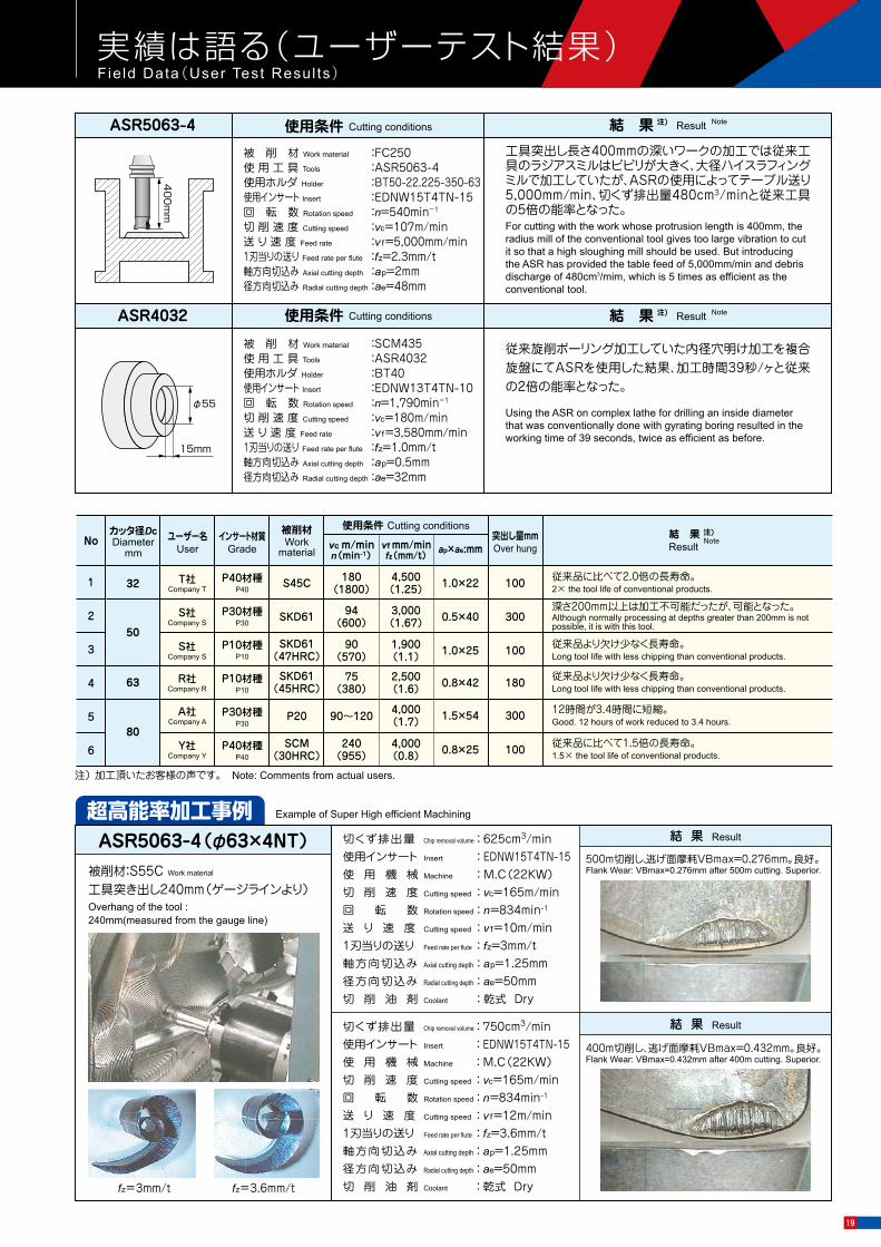
Example of Super High efficient Machining 超高能率加工事例
No
1
2
3
4
5
6
カッタ径DcDiameter
mm
50
32
63
80
ユーザー名User
A社Company A
インサート材質Grade
被削材Work
material
P20
使用条件 Cutting conditions
90~120 4,000(1.7) 1.5×54
突出し量mmOver hung
300
ASR5063-4 使用条件 Cutting conditions
ASR4032
φ55
15mm
工具突出し長さ400mmの深いワークの加工では従来工具のラジアスミルはビビリが大きく、大径ハイスラフィングミルで加工していたが、ASRの使用によってテーブル送り5,000mm/min、切くず排出量480cm3/minと従来工具の5倍の能率となった。For cutting with the work whose protrusion length is 400mm, the radius mill of the conventional tool gives too large vibration to cut it so that a high sloughing mill should be used. But introducing the ASR has provided the table feed of 5,000mm/min and debris discharge of 480cm3/mim, which is 5 times as efficient as the conventional tool.
従来旋削ボーリング加工していた内径穴明け加工を複合旋盤にてASRを使用した結果、加工時間39秒/ヶと従来の2倍の能率となった。
Using the ASR on complex lathe for drilling an inside diameter that was conventionally done with gyrating boring resulted in the working time of 39 seconds, twice as efficient as before.
40
0m
m
ap×ae:mmvc m/minn(min-1)
vf mm/minfz(mm/t)
S社Company S SKD61 94
(600)3,000
(1.67) 0.5×40 300深さ200mm以上は加工不可能だったが、可能となった。Although normally processing at depths greater than 200mm is not possible, it is with this tool.
S社Company S
SKD61(47HRC)
90(570)
1,900(1.1) 1.0×25 100 従来品より欠け少なく長寿命。
Long tool life with less chipping than conventional products.
R社Company R
SKD61(45HRC)
75(380)
2,500(1.6) 0.8×42 180 従来品より欠け少なく長寿命。
Long tool life with less chipping than conventional products.
T社Company T
P40材種P40
P30材種P30
P10材種P10
P10材種P10
P30材種P30
P40材種P40
S45C 180(1800)
4,500(1.25) 1.0×22 100 従来品に比べて2.0倍の長寿命。
2× the tool life of conventional products.
Y社Company Y
SCM(30HRC)
240(955)
4,000(0.8) 0.8×25 100 従来品に比べて1.5倍の長寿命。
1.5× the tool life of conventional products.
12時間が3.4時間に短縮。Good. 12 hours of work reduced to 3.4 hours.
被 削 材 Work material :FC250使 用 工 具 Tools :ASR5063-4使用ホルダ Holder :BT50-22.225-350-63使用インサート Insert :EDNW15T4TN-15回 転 数 Rotation speed :n=540min-1
切 削 速 度 Cutting speed :vc=107m/min送 り 速 度 Feed rate :v f=5,000mm/min1刃当りの送り Feed rate per flute :fz=2.3mm/t軸方向切込み Axial cutting depth :ap=2mm径方向切込み Radial cutting depth :ae=48mm
被 削 材 Work material :SCM435使 用 工 具 Tools :ASR4032使用ホルダ Holder :BT40使用インサート Insert :EDNW13T4TN-10回 転 数 Rotation speed :n=1,790min-1
切 削 速 度 Cutting speed :vc=180m/min送 り 速 度 Feed rate :v f=3,580mm/min1刃当りの送り Feed rate per flute :fz=1.0mm/t軸方向切込み Axial cutting depth :ap=0.5mm径方向切込み Radial cutting depth :ae=32mm
結 果 注)
ResultNote
注) 加工頂いたお客様の声です。 Note: Comments from actual users.
Result結 果 注) Note
使用条件 Cutting conditions Result結 果 注) Note
実績は語る(ユーザーテスト結果) Field Data(User Test Resul ts)
400m切削し、逃げ面摩耗VBmax=0.432mm。良好。Flank Wear: VBmax=0.432mm after 400m cutting. Superior.
結 果 Result
被削材:S55C Work material
工具突き出し240mm(ゲージラインより)Overhang of the tool : 240mm(measured from the gauge line)
fz=3mm/t fz=3.6mm/t
500m切削し、逃げ面摩耗VBmax=0.276mm。良好。Flank Wear: VBmax=0.276mm after 500m cutting. Superior.
結 果 ResultASR5063-4(φ63×4NT) 切くず排出量 Chip removal volume : 625cm3/min使用インサート Insert : EDNW15T4TN-15使 用 機 械 Machine : M.C(22KW)切 削 速 度 Cutting speed : vc=165m/min回 転 数 Rotation speed : n=834min-1
送 り 速 度 Cutting speed : v f=10m/min1刃当りの送り Feed rate per flute : fz=3mm/t軸方向切込み Axial cutting depth : ap=1.25mm径方向切込み Radial cutting depth : ae=50mm切 削 油 剤 Coolant : 乾式 Dry
切くず排出量 Chip removal volume : 750cm3/min使用インサート Insert : EDNW15T4TN-15使 用 機 械 Machine : M.C(22KW)切 削 速 度 Cutting speed : vc=165m/min回 転 数 Rotation speed : n=834min-1
送 り 速 度 Cutting speed : v f=12m/min1刃当りの送り Feed rate per flute : fz=3.6mm/t軸方向切込み Axial cutting depth : ap=1.25mm径方向切込み Radial cutting depth : ae=50mm切 削 油 剤 Coolant : 乾式 Dry
プログラム上の刃先形状定義方法 To define cutting edge shape for programming07● 荒取り加工時は、ラジアスミル、近似コーナR(R3)としてインプットすれば下図のインサートR別の削り残し代で加工
できます。・By inputting Radius Mill Approximate Corner R (R3), insert R cutting remains processing as shown below is possible for roughing procedures.
φ60
R16
φ70
5mm
R25
工具 Tool :ASRφ32(ASRL4032)Vc=93m/min. fz=1.5mm/tエアーブロー Air-blow突出し量 Overhang :130mm ロードメータ Load Meterヘリカルピッチ=1.0mm 35%(5.3kw) 1.5mm 45%(6.8kw) 2.0mm 85%(12.8kw)
工具 Tool :ASRφ50(ASRL5050)Vc=141m/min. fz=1.5mm/tae=5mm,エアーブロー Air-blow突出し量 Overhang :150mm ロードメータ Load Meterヘリカルピッチ=1.0mm 25%(3.8kw) 1.5mm 35%(5.3kw) 2.0mm 45%(6.8kw) 2.5mm 80%(12kw)
Herical Pitch Herical Pitch
Vc-L線図(切削速度 : Vcと工具寿命 : Lの関係) vc-L Line Graph (Relationship between Cutting Speed : vc and Cutting Length : L)
削り残し代χ=約0.5mm(R10 : 突き出し量4~ 5Dc以上用)
削り残し代χ=約0.6mm(R15 : 突き出し量5Dc以下用)
Remains χ = approx. 0.5mmR10 : Over hung 4~5Dc or more recommended
Remains χ = approx. 0.6mmR15 : Over hung 5Dc or less recommended
ED W T TN-15 ED W T TN-10
χ : 削り残し代Remains
プログラミングR : R3Approximate Input Corner R : R3
R3
100 20 30 40 50 600
100
200
300
400
0.6 15
切削長 L Cutting Length L (m)
φ80×1NTによるS50C切削
切削
速度
Vc
Cutti
ng S
peed
(m/m
in)
Milling of S50C withφ80 × 1NT
R1
5
rε2
5°
10°
7.7
3.3
R1
0
rε2
5°
10°
5.6
2.9
インサート刃先形状略図 Insert tip of the blade shape rough sketch
切削データ Performance Data
ヘリカル加工と所要動力 使用機械:立形M.C15KW 被削材:S50C(220HB) Helical Cutting and Required Power Machine: Vertical type M.C15KW Work: S50C (220HB)
繰り広げ加工 Expansion Boring直彫り加工 General Boring
切削性能 Cutt ing performance
19

図、表等のデータは試験結果の一例であり、保証値ではありません。「Epoch」「 」「 」は日本における三菱日立ツール株式会社の登録商標です。The diagrams and table data are examples of test results, and are not guaranteed values."Epoch" , “ ” and “ ” are registered trademarks of Mitsubishi Hitachi Tool Engineering, Ltd. in Japan.
ホームページ
工具選定データベース 【TOOL SEARCH】
フリーダイヤル技術相談http://www.mmc-hitachitool.co.jp
本社 〒130-0026 東京都墨田区両国4-31-11(ヒューリック両国ビル8階)03-6890-5101
+81-3-6890-5103FAX 03-6890-5134FAX +81-3-6890-5128International Sales Dept .:
安 全 上 の ご 注 意 Attentions on Safety
営業企画部 ☎03-6890-5102 FAX03-6890-5134 海外営業部 ☎03-6890-5103 FAX03-6890-5128
Printed in JAPANベジタブルインクで印刷しています。Printed using vegetable oil ink.
掲載価格は消費税抜きの単価を表示しております。予告なく、改良・改善のために仕様変更することがあります。Specifications for the products listed in this catalog are subject to change without notice due to replacement or modification.
☎☎☎☎☎☎
東京営業所東北営業所新潟営業所東関東営業所長野営業所北関東営業所神奈川営業所
名古屋営業所大阪営業所松江営業所中四営業所九州営業所北九州営業所
☎☎☎☎☎☎☎
052-687-915006-7668-01900852-40-0300082-536-2001092-289-7010093-434-2640
FAX052-687-9144FAX06-7668-0194FAX0852-40-0617FAX082-536-2003FAX092-289-7012FAX093-434-6846
03-6890-5110022-208-51000258-29-30390294-88-94300268-21-37000276-59-6001046-400-9429
FAX03-6890-5133FAX022-208-5102FAX0258-29-3092FAX0294-88-9432FAX0268-21-3711FAX0276-59-6005FAX046-400-9435
ヨーロッパ/MMC Hitachi Tool Engineering Europe GmbH Itterpark 12, 40724 Hilden, Germany. TEL : +49-(0)2103-24820, FAX : +49-(0)2103-248230中 国/菱材日立刀具(上海)有限公司 郵編200003中国上海市黄浦区南京西路288号(創興金融中心1101室) TEL:+86-(0)21-3366-3058, FAX:+86-(0)21-3366-3050アメリカ/MITSUBISHI MATERIALS U.S.A. CORPORATION 41700 Gardenbrook Road, Suite 120, Novi, MI 48375-1320 U.S.A. TEL : +1(248)308-2620, FAX :+1(248)308-2627タ イ/MMC Hardmetal(Thailand)Co.,Ltd. HT-Division CTI Tower 24 Floor, 191/32 Ratchadapisek Road, Klongtoey, Klongtoey, Bangkok 10110, Thailand TEL:+66-(0)2-661-8170 FAX:+66-(0)2-661-8175イ ン ド/Hitachi Metals (India) Pvt. Ltd. Plot No 94 & 95,Sector 8, IMT Manesar, Gurgaon -122050, Haryana, India TEL : +91-124-4812315, FAX :+91-124-2290015
1. Attentions regarding handling
2. Attentions regarding mounting
3. Attentions during use
1. 取扱上のご注意(1)工具をケース(梱包)から取り出す際は、足元への落下あるいは素手の指先へ落して怪我
をしないように十分なご注意をお願いします。(2)インサートをセットして実際にご使用する場合は、切れ刃を素手で直接触れないように注
意してください。
2. 取付け時のご注意(1)ご使用にあたって、インサートのセッティングは確実に行っていただき、アーバ等への取付
けも確実に行ってください。(2)ご使用中に、異常な振動等が発生した場合は、直ちに機械を停止させて、その振動の原因
を除いてください。
3. 使用上のご注意(1)切削工具あるいは被削材の寸法・回転の方向は、あらかじめ確認しておいてください。(2)標準切削条件表の数値は、新しい作業の立上げの目安としてご利用ください。切込みが大きい
場合、使用機械の剛性が小さい場合あるいは被加工物の性状に応じて切削条件を適正に調整してご使用ください。
(3)インサートは硬質の材料です。ご使用中に破損して飛散する場合があります。また、切りくずが飛散することがあります。これらの飛散物等は作業者を切傷させ、火傷あるいは目に入って負傷させる恐れがありますので、工具をご使用中はその周囲に安全カバーを取付け、保護めがね等の保護具を着用して安全な環境下での作業をお願いいたします。・引火や爆発の危険のあるところでは使用しないでください。・不水溶性切削油は、火災の恐れがありますので使用しないでください。
(4)工具を本来の目的以外に使用したり、改造したりしないでください。4. 工具に関して、安全上の問題点・不明の点・その他ご相談がありましたら フリーダイヤル技術相談 へ
お問い合わせください。
2017-10(ME-RT3)2012-1:FP