general super ff 4100,4125... · general mexico super 4100 ff & 4125 ff ... made to the...
TRANSCRIPT


2
GENERAL
Mexico Super 4100 FF & 4125 FF - Installation
Key to symbols
GB = United Kingdom IE = Ireland (Countries of destination)
PMS = Maximum operating pressure of water
C12 = A room sealed appliance designed for connection viaducts to a horizontal terminal, which admits fresh air tothe burner and discharges the products of combustionto the outside through orifices which, in this case, areconcentric. The fan is down stream of the combustionchamber.
I2H = An appliance designed for use on 2nd Family gas,Group H only.
Note.Gas consumption is calculated using a calorific value of38.7 MJ/m3 (1038 Btu/ft3) gross or 34.9 MJ/m3 (935 Btu/ft3)nett. To obtain the gas consumption at a different calorificvalue:-
a. For l/s - divide the gross heat input (kW) by the grossC.V. of the gas (MJ/m3)
b. For ft3/h - divide the gross heat input (Btu/h) by the
gross C.V. of the gas (Btu/ft3)
c. The appliance is preset at the factory to the highestnominal rating.
* The value is used in the UK Government's Standard Assessment Procedure (SAP) for energy rating of dwellings.
The test data from which it has been calculated have been certified by a notified body.
CAUTION. To avoid the possibility of injury during the installation, servicing or cleaning ofthis appliance, care should be taken when handling edges of sheet steel components
Boiler Size 4100 FF 4125 FF
Gas Supply Connection in. BSP Rc 1/2 (1/2)
Number of Boiler Sections 4 5
Flow and Return Connections Rc 1 (1" BSP)
MAXIMUM Static Water Head m (ft.) 30.5 (100) (3 bar)
MINIMUM Static Water Head m (ft.) 1.0 (3.3)
Electrical Supply (Power Consumption) 230 V ~ 50 Hz (100 W)
Fuse Rating External 3 A Internal 1A to BS4265
Water Content litre (gal.) 9.8 (2.1) 12.2 (2.7)
Dry Weight kg. (lb.) 113 (249) 136 (300)
Boiler Size Height mm (in.) 850 (33.5)
Width mm (in.) 440 (17.4)
Depth mm (in.) 533 (21.0) 600 (23.6)
Gas Type Natural 2 H
Gas Supply Pressure 20 mb
Flue duct diameter mm (in.) 100 (4.0)
Flue duct length (max) m (ft) 2 (6.5) 1 (3.25)
Boiler Size 4100 FF 4125 FF
Boiler Input
(GROSS) kW (Btu/h) 36.2 (123 500) 45.2 (154 200)
l/s (ft.3/h) 0.94 (119.0) 1.17 (148.6)
Boiler Input
(NETT) kW (Btu/h) 32.6 (111 200) 40.7 (138 900)
Boiler Output to Water kW (Btu/h) 29.3 (100 000) 36.6 (125 000)
Burner Setting Pressure (hot)mbar (in w.g.) 11.6 (4.6) 12.7 (5.1)
Seasonal Efficiency (SEDBUK)* Band D [78.8]% [78.5]%
Table 1 - General Data
Table 2 - Performance Data
3
GENERAL
Mexico Super 4100 FF & 4125 FF - Installation
NOTE TO THE INSTALLER: LEAVE THESEINSTRUCTIONS ADJACENT TO THE GAS METER.ALSO COMPLETE THE BENCHMARK LOG BOOK
AND GIVE THIS TO THE CUSTOMER.
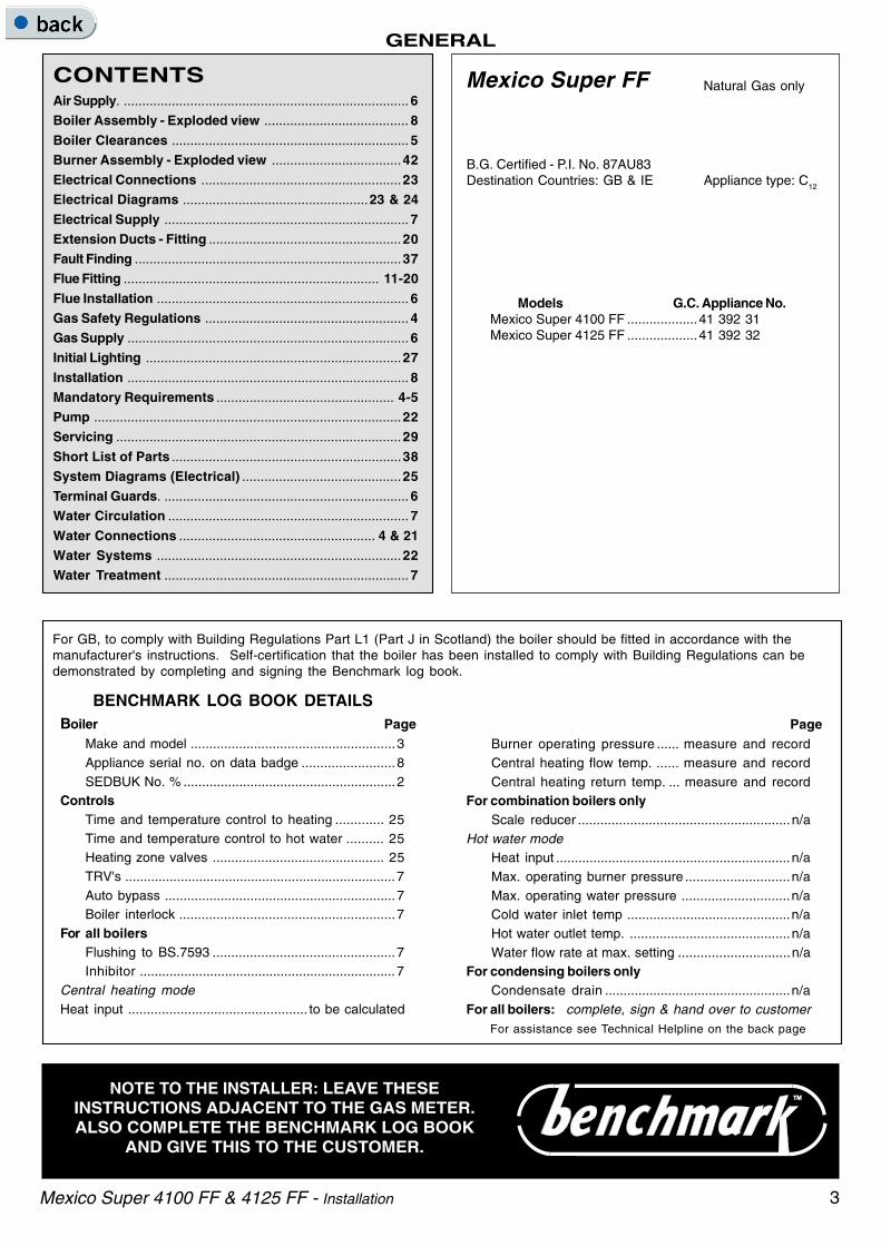
CONTENTSAir Supply. ............................................................................. 6Boiler Assembly - Exploded view ....................................... 8
Boiler Clearances ................................................................ 5Burner Assembly - Exploded view ...................................42Electrical Connections ......................................................23Electrical Diagrams ..................................................23 & 24
Electrical Supply .................................................................. 7Extension Ducts - Fitting ....................................................20Fault Finding ........................................................................37Flue Fitting ..................................................................... 11-20
Flue Installation .................................................................... 6Gas Safety Regulations ....................................................... 4Gas Supply ............................................................................ 6Initial Lighting .....................................................................27
Installation ............................................................................ 8Mandatory Requirements ................................................ 4-5Pump ...................................................................................22Servicing .............................................................................29
Short List of Parts ..............................................................38System Diagrams (Electrical) ...........................................25Terminal Guards. .................................................................. 6Water Circulation ................................................................. 7
Water Connections ..................................................... 4 & 21Water Systems ..................................................................22Water Treatment .................................................................. 7
Mexico Super FF
B.G. Certified - P.I. No. 87AU83Destination Countries: GB & IE Appliance type: C12
Models G.C. Appliance No.Mexico Super 4100 FF ...................41 392 31Mexico Super 4125 FF ...................41 392 32
Natural Gas only
BENCHMARK LOG BOOK DETAILSBoiler Page
Make and model .......................................................3Appliance serial no. on data badge .........................8SEDBUK No. % .........................................................2
ControlsTime and temperature control to heating ............. 25Time and temperature control to hot water .......... 25Heating zone valves .............................................. 25TRV's .........................................................................7Auto bypass ..............................................................7Boiler interlock ..........................................................7
For all boilersFlushing to BS.7593 .................................................7Inhibitor .....................................................................7
Central heating modeHeat input ................................................ to be calculated
For assistance see Technical Helpline on the back page
PageBurner operating pressure ...... measure and recordCentral heating flow temp. ...... measure and recordCentral heating return temp. ... measure and record
For combination boilers onlyScale reducer .........................................................n/a
Hot water modeHeat input ...............................................................n/aMax. operating burner pressure ............................n/aMax. operating water pressure .............................n/aCold water inlet temp ............................................n/aHot water outlet temp. ...........................................n/aWater flow rate at max. setting ..............................n/a
For condensing boilers onlyCondensate drain ..................................................n/a
For all boilers: complete, sign & hand over to customer
For GB, to comply with Building Regulations Part L1 (Part J in Scotland) the boiler should be fitted in accordance with themanufacturer's instructions. Self-certification that the boiler has been installed to comply with Building Regulations can bedemonstrated by completing and signing the Benchmark log book.

4
GENERAL
Mexico Super 4100 FF & 4125 FF - Installation
INTRODUCTIONMexico Super FF above range is of floor standing, fanned fluegas boilers. They are rated to provide central heating outputsof 29.3 kW (100,000 Btu/h) to36.6 kW (125,000 Btu/h).
The boiler has a cast iron heat exchanger and is suppliedfully assembled, complete with a white enamelled mild steelcasing.
A door at the top of the casing front panel hinges down,revealing the boiler thermostat control (and programmer, iffitted).
The boilers are suitable, as standard, for connection to open-vented systems ONLY - an overheat thermostat kit is availableto allow the boiler to be used on sealed water systems.
The systems may be:• pumped or gravity circulating indirect DHW only• pumped central heating only• pumped central heating combined with either a pumped or
gravity circulating indirect DHW circuit.
OPTIONAL EXTRA KITSExtension Duct Kit
Programmer Kit Fits neatly within the casing. Separatefitting instructions are included with thiskit.
Overheat is available to allow the boiler to be used
Thermostat Kit on sealed water systems.
GAS SAFETYCURRENT GAS SAFETY (INSTALLATION AND USE)REGULATIONS OR RULES IN FORCE.The appliance is suitable only for installation in GB and IEand should be installed in accordance with the rules in force.
In GB, the installation must be carried out by a CORGIRegistered Installer. It must be carried out in accordance withthe relevant requirements of the:• Gas Safety (Installation and Use) Regulations• The appropriate Building Regulations either The Building
Regulations, The Building Regulations (Scotland),Building Regulations (northern Ireland).
• The Water Fittings Regulations or Water byelaws inScotland.
• The Current I.E.E. Wiring Regulations.
Where no specific instructions are given, reference should bemade to the relevant British Standard Code of Practice.
In IE, the installation must be carried out by a CompetentPerson and installed in accordance with the current edition ofI.S.813 "Domestic Gas Installations", the current BuildingRegulations and reference should be made to the current ETCIrules for electrical installation.
Detailed recommendations are contained in the following BritishStandard Codes of Practice:
BS. 6891 Low pressure installation pipes.
BS. 6798 Installation of gas fired hot water boilers of ratedinput not exceeding 60 kW.
BS. 5449:1 Forced circulation hot water systems (small boreand microbore domestic central heatingsystems).
BS. 5546 Installation of gas hot water supplies fordomestic purposes (2nd Family Gases).
BS. 5440: 1 Flues for gas appliances of rated input notexceeding 60 kW.
BS. 5440: 2 Ventilation for gas appliances of rated input notexceeding 60 kW.
BS 7593 Treatment of water in Domestic Hot WaterCentral Heating Systems.
Health and Safety Document No. 635.
The Electricity at Work Regulations, 1989.
Manufacturer’s notes must NOT be taken in any way as overridingstatutory obligations.
IMPORTANT. These appliances are certificated by the BritishStandards Institution for safety and performance. It is important,therefore, that no external control devices, e.g. flue dampers,economisers etc., are directly connected to these appliancesunless covered by these Installation and Servicing Instructionsor otherwise recommended by Caradon Ideal Limited in writing.If in doubt please enquire.
Any direct connection of a control device not approved by CaradonIdeal Limited could invalidate the BSI Certification and the normalappliance warranty. It could also infringe the Gas SafetyRegulations and the above regulations or other statutoryrequirements.
1. This appliance is NOT suitable foruse in a direct hot water system.
2. If the boiler is to be used on a sealedsystem, an Overheat Thermostat Kitis available and must be installed inaccordance with the instructionssupplied with the kit.
1 BOILER WATER CONNECTIONS
Dimension A B
4100 FF 299mm (11 3/4") 533mm (21")
4125 FF 373mm (14 5/8") 600mm (23 5/8")

5
GENERAL
Mexico Super 4100 FF & 4125 FF - Installation
Where a room-sealed appliance is installed in a roomcontaining a bath or shower then the appliance and anyelectrical switch or appliance control utilising mains electricityshould be so situated that it cannot be touched by a personusing the bath or shower.
Where installation will be in an unusual location, specialprocedures may be necessary and BS.6798 gives detailedguidance on this aspect.
Compartment InstallationsA compartment used to enclose the boiler MUST be designedand constructed specially for this purpose.An existing cupboard or compartment may be used, providing itis modified for the purpose.
In both cases details of essential features of cupboards/compartment design, including airing cupboard installation,are to conform to the following:
!!!!! BS. 6798.
!!!!! The position selected for installation MUST allowadequate space for servicing in front of the boilerand for air circulation around the boiler.Side clearance is only necessary for installation. Theamount of side clearance will depend upon the type ofconnection used.
! This position MUST also permit the provision of asatisfactory flue termination.
! For the minimum clearances required for safety andsubsequent service see Frame 2.
SAFE HANDLING OF SUBSTANCESCare should be taken when handling the boiler insulation panels,which can cause irritation to the skin. No asbestos, mercury orCFCs are included in any part of the boiler.
LOCATION OF BOILERThe boiler must be installed on a flat and level floor, capable ofadequately supporting the weight of the boiler and any ancillaryequipment.
The boiler may be fitted on a combustible floor.
Insulation is not necessary, unless required by the local authority.
The boiler must not be fitted outside.
Timber Framed Buildings
If the boiler is to be fitted in a timber framed building it should befitted in accordance with the Institute of Gas Engineers documentIGE/UP/7 : 1998.
Bathrooms
The boiler may be installed in any room or internal space,although particular attention is drawn to the requirements of thecurrent I.E.E. (BS 7671) Wiring Regulations and, in Scotland,the electrical provisions of the building regulations applicablein Scotland with respect to the installation of the boiler in aroom or internal space containing a bath or shower. ForIreland reference should be made to the current ETCI rules forelectrical installations and I.S. 813: 2002.
2 FLOOR MOUNTING AND BOILER CLEARANCES
Flammable materials must not be placed in close proximity to the appliance. Materialsgiving off flammable vapours must not be stored in the same room as the appliance.
Floor mounting1. The floor must be flat, level and of suitable load
bearing capacity.
2. The back of the boiler may be fitted up to the wall.
Boiler clearancesThe minimum overall dimensions of the space inwhich the boiler is to operate and to facilitateservicing are as follows:-
Additional space will be required for installation,depending upon site conditions.
IMPORTANT.
In order to facilitate gas connection, a clearance of atleast 100 mm (4") must be available at either the lefthand side or the right hand side DURINGinstallation. Refer to Frame 39.
In addition a MINIMUM clearance of 533 mm (21")MUST be available at the front of the boiler, forservicing.
Boiler Flue Overall Space Dimension Min Side Clearance 'A'
Model Length Depth Height Width Width Rear Flue Side/Top Flue
Rear Flue Side/Top Flue
114 to 600 (4 1/2 to 23 5/8") 533 (21") 870 (34 1/4") 460 (18 1/8") 510 (20 1/8") 10 (3/8") 35(1 3/8")
4100 FF 600 to 2000 533 (21") 870 (34 1/4") 510 (20 1/8") 510 (20 1/8") 35 (1 3/8") 35(1 3/8")
(23 5/8 to 78 3/4")
114 to 600 (4 1/2 to 23 5/8") 600 (23 5/8") 870 (34 1/4") 550 (21 5/8") 550 (21 5/8") 55 (2 1/4") 55(2 1/4")
4125 FF 600 to 1000 600 (23 5/8") 870 (34 1/4") 550 (21 5/8") 550 (21 5/8") 55 (2 1/4") 55(2 1/4")
(23 5/8" to 39 1/4")

6
GENERAL
Mexico Super 4100 FF & 4125 FF - Installation
GAS SUPPLYThe local gas supplier should be consulted, at the installationplanning stage, in order to establish the availability of anadequate supply of gas. An existing service pipe must NOT beused without prior consultation with the local gas supplier.The boiler is to be installed only on a gas supply with agoverned meter.A gas meter can only be connected by the local gas supplier orby a local regional contractor.Check that the appliance is suitable for the proposed gassupply. An existing meter should be checked, preferably by thegas supplier, to ensure that the meter is adequate to deal withthe rate of gas supply required. A minimum gas pressure of20 mbar MUST be available at the boiler inlet, with the boileroperating.Installation pipes MUST be fitted in accordance with BS. 6891.In IE refer to I.S. 813:2002. Pipework from the meter to theboiler MUST be of an adequate size. Both 100 FF and 125 FFmodels should be piped in 22mm minimum. The final metremay be run in 15mm if it is visible.The complete installation MUST be tested for gas soundnessand purged as described in the above code.
FLUE INSTALLATIONSome pluming may occur at the termination, so terminalpositions where this could cause a nuisance should be avoided.The flue must be installed in accordance with therecommendations of BS.5440-1:2000. In IE refer toI.S.813:2002.
The following notes are intended for general guidance:-
1. The boiler MUST be installed so that the terminal isexposed to external air.
2. It is important that the position of the terminal allows thefree passage of air across it at all times.
3. Minimum acceptable spacing from the terminal toobstructions and ventilation openings are specified in Table 3.
4. Where the lowest part of the terminal is fitted less than 2m(6'6") above a balcony, above ground or above a flat roof towhich people have access then the terminal MUST beprotected by a purpose designed guard. The minimumspacing in Table 3, Nos. 2,3, 4, 5 and 6 would be 75mm inorder to allow a terminal guard to be fitted.Terminals guards are available from boiler suppliers - askfor TFC Flue Guard, Model K1. In case of difficulty seekadvice from:
Grasslin (UK) Ltd., Tower House, Vale Rise, Tonbridge,Kent TN9 1TB.Tel: +44 (0) 1732 359 888. Fax: +44 (0) 1732 354 445www.tfc-group.co.uk
Ensure that the guard is fitted centrally.5. The air inlet/products outlet duct and the terminal of the
boiler MUST NOT be closer than 25mm (1") to combustiblematerial. Detailed recommendations on the protection ofcombustible material are given in BS.5440-1:2000. In IErefer to I.S. 813:2002.
6. Where it is essential that the terminal wall plate is fitted,i.e. wall thicknesses over 600mm (23 1/2") or with aninaccurately cut hole, the minimum spacing in Table 3 -Nos. 2, 3, 4, 5 & 6 - would be 60mm (2 1/2") in order to allowthe terminal wall plate to be fitted.
7. The flue assembly shall be so placed or shielded as toprevent ignition or damage to any part of any building.
IMPORTANT. It is absolutely ESSENTIAL to ensure, in practice,that products of combustion discharging from the terminalcannot re-enter the building or any other adjacent buildingthrough ventilators, windows, doors, other sources of naturalair infiltration or forced ventilation/air conditioning. If this shouldoccur, the appliance MUST be turned OFF, labelled 'unsafe' andcorrective action taken.
TERMINALWARNINGFor top outlet installation (100 FF only) the flue terminal MUSTalways be in the horizontal position.
The terminal assembly can be adapted to accommodate variouswall thicknesses. Refer to Frames 7 & 36.
AIR SUPPLYDetailed recommendations for air supply are given inBS.5440:2. In IE refer to I.S. 813:2002.
The following notes are for general guidance:
1. It is NOT necessary to have a purpose provided air vent inthe room or internal space in which the boiler is installed.
2. If the boiler is to be installed in a cupboard or compartment,permanent air vents are required (for cooling purposes) inthe cupboard/compartment, at both high and low levels. Theair vents must either communicate with room/internalspace, or be direct to outside air. The minimum effectiveareas of the permanent air vents, required in the cupboard/compartment, are specified as follows and are related tomaximum rated heat input.
3. Both air vents MUST communicate with the same room orinternal space or MUST be on the same wall to outside air.
4. In siting the air vents care must be taken to avoid thefreezing of pipework.
Table 4 - High and low vent areas
Boiler Air from room/internal Air direct fromspace cm2 (in.2) outside cm2 (in.2)
High level Low level High level Low level
4100 FF 354 (55) 354 (55) 177 (28) 177 (28)
4125 FF 438 (68) 438 (68) 219 (34) 219 (34)
Table 3 - Balanced flue terminal position
Terminal Position Minimum Spacing
1a. Directly BELOW an opening, air brick,opening window, etc. 300 mm (12")
1b. Directly ABOVE an opening, air brick,opening window, etc. 300 mm (12")
1c. HORIZONTALLY to an opening,air brick,opening window, etc. 300 mm (12")
2. Below guttering, drain pipes or soilpipes 75 mm ( 3")
3. Below eaves 200 mm ( 8")
4. Below balconies or a car port roof 200 mm ( 8")
5. From vertical drain pipes or soil pipes 150 mm ( 6")
6. From an internal or external corner orto a boundary alongside the terminal 300 mm ( 12")
7. Above adjacent ground, roof orbalcony level 300 mm (12")
8. From a surface or a boundaryfacing the terminal 600 mm (24")
9. From a terminal facing a terminal 1200 mm (48")
10. From an opening in a car port(e.g. door or window) into dwelling 1200 mm (48")
11. Vertically from a terminal on the same wall 1500 mm (60")
12. Horizontally from a terminal on the wall 300 mm (12")

7
GENERAL
Mexico Super 4100 FF & 4125 FF - Installation
Caradon Ideal Limited recommend Water Treatment inaccordance with the Benchmark Guidance Notes on WaterTreatment in Central Heating Systems.Caradon Ideal Limited recommend the use of Fernox, GE BetzSentinel or Salamander water treatment products, which mustbe used on accordance with the manufacturers instructions.
For further information contact:
Fernox Manufacturing Co. Ltd, Cookson Electronics, Forsyth Road,Sheerwater, Woking, Surrey. GU21 5RZ. Tel. +44 (0) 1799 521133or
G E Betz Ltd, Sentinel Division, Foundry Lane, Widnes, Cheshire,WA8 8UD. Tel. +44 (0) 151 424 5351or
Salamander Engineering Ltd, Unit 24, Reddicap Trading Estate,Sutton Coldfield, West Midlands B75 7BU. Tel. +44 (0) 121 378 0952
Notes.1. It is most important that the correct concentration of the
water treatment products is maintained in accordance withthe manufacturers' instructions.
2. If the boiler is installed in an existing system any unsuitableadditives MUST be removed by thorough cleansing.BS7593:1992 details the steps necessary to clean adomestic heating system.
3. In hard water areas, treatment to prevent limescale may benecessary - however the use of artificially softened water isNOT permitted.
4. Under no circumstances should the boiler be fired beforethe system has been thoroughly flushed.
BOILER CONTROL INTERLOCKS
Caradon Ideal Limited recommend that heating systems utilisingfull thermostatic radiator valve control of temperature in individualrooms should also be fitted with a room thermostat controllingthe temperature in a space served by radiators not fitted withsuch a valve as stated in BS. 5449.
Central heating systems controls should be installed to ensure theboiler is switched off when there is no demand for heating or hot water.
When thermostatic radiator valves are used, the space heatingtemperature control over a living / dining area or hallway having aheating requirement of at least 10% of the boiler heat outputshould be achieved using a room thermostat, whilst other roomsare individually controlled by thermostatic radiator valves.However, if the system employs thermostatic radiator valves onall radiators, or two port valves without end switches, then abypass circuit must be fitted with an automatic bypass valve toensure a flow of water should all valves be in the closed position.
ELECTRICAL SUPPLYWARNING. The appliance MUST be efficiently earthed.
Wiring external to the appliance MUST be in accordance withthe current I.E.E. (BS 7671) Wiring Regulations and any localregulations which apply. For Ireland reference should be madeto the current ETCI rules for electrical installations.
The boiler is supplied for 230 V ~ 50 Hz single phase. Thefuse rating is 3A.
Connection must be made in a way that allows completeisolation of the electrical supply - such as a double pole switch,having a 3mm (1/8") contact separation in both poles, or a plugand socket serving only the boiler and system controls.
The means of isolation must be accessible to the user afterinstallation.
For bathroom installations the point of connection to the mainsmust be situated outside the bathroom.
4100 FF & 4125 FF
4100
FF
4125
FF
ME
X 1
877
WATER CIRCULATION SYSTEMThe boiler must NOT be used for direct hot water supply or forsealed systems. The boiler is suitable for connection topumped open vent central heating systems, pumped centralheating combined with pumped or gravity indirect domestic hotwater supply systems.
The boiler is NOT suitable for gravity heating systems. Thehydraulic resistances of the boilers at maximum output with11oC (20 oF) temperature differentials are shown in the graphbelow.
The central heating system should be in accordance withBS. 6798 and, in addition, for smallbore and microboresystems, BS. 5449:1.
The domestic hot water system, if applicable, should be inaccordance with the relevant recommendations of BS. 5546.
Copper tubing to BS. 2871:1 is recommended for watercarrying pipework.
The hot water storage cylinder MUST be of the indirect type andshould preferably be manufactured of copper.
Single feed, indirect cylinders are not recommended and MUSTNOT be used on sealed systems.
The hot water cylinder and ancillary pipework not forming partof the useful heating surface should be lagged to prevent heatloss and any possible freezing - particularly where pipes runthrough roof spaces and ventilated underfloor spaces.
IMPORTANT.
A minimum length of 2 m of copper pipe MUST be fitted to bothflow and return connections from the boiler before connectionto any plastic piping.
The boiler must be vented. If venting cannot be done via a flowconnection a separate vent MUST be fitted by the installer.
Draining taps MUST be located in accessible positions, whichpermit the draining of the whole system - including the boilerand hot water storage vessel. They should be at least 1/2" BSPnominal size and be in accordance with BS. 2879.
If required, a drain tap (not supplied) may be fitted to an unusedbottom (1" BSP) tapping on the front of the boiler.
WATER TREATMENTThese boilers incorporate a cast iron heat exchanger.IMPORTANT. The application of any other treatment to thisproduct may render the guarantee of Caradon Ideal LimitedINVALID.
Dotted lines indicate flow rates equivalent to atemperature rise of 11
oC (20
oF)
Water Flow Rate and Pressure Loss
8 Mexico Super 4100 FF & 4125 FF - Installation
INSTALLATIONIN
STA
LL
AT
ION
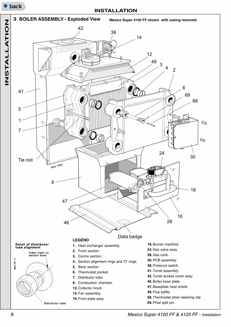
3 BOILER ASSEMBLY - Exploded View Mexico Super 4100 FF shown with casing removed.
4238
12
14
49
41
5
1
7
Tie rod
8
46
Mex1880
Data badge
2816
18
30
6
69
68
243
24
47
18. Burner manifold.
24. Gas valve assy.
28. Gas cock.
30. PCB assembly.
38. Pressure switch.
41. Turret assembly.
42. Turret access cover assy.
46. Boiler base plate.
47. Baseplate heat shield.
49. Flue baffle.
68. Thermostat phial retaining clip
69. Phial split pin.
LEGEND1. Heat exchanger assembly.
2. Front section.
3. Centre section.
4. Section alignment rings and 'O' rings.
5. Back section.
6. Thermostat pocket.
7. Distributor tube.
8. Combustion chamber.
12. Collector hood.
14. Fan assembly.
16. Front plate assy.
INS
TA
LL
AT
ION

9Mexico Super 4100 FF & 4125 FF - Installation
INSTALLATION
INS
TA
LL
AT
ION
5 BOILER CASING REMOVAL
To install the boiler the casing MUST be removed.
1. Undo the 2 screws and lift off the lower front panel.
2. Remove 2 screws and lift off the grille assembly.
3. Disconnect the in-line electrical connector betweenthe control box and the PCB box.
4. Remove the thermostat phial from the pocket asshown in Frame 6.
The boiler is supplied fully assembled in Pack A,together with a standard flue assembly for lengthsup to 600mm (23 1/2") rear or side flue outlet inPack B.
Unpack and check the contents.
4 UNPACKING
complete boiler assembly
BOILER HARDWARE PACK
! 1" BSP plugs - 5 off.
! 1" x 1/2" BSP reducing bush - 1 off.
! Distributor tube - 1off.
! 28mm Comp nut - 1off.
! 28mm Olive - 1off.
! Thermostat pocket -1 off
! Thermostat clip (RS 3/50, RS 3/60,RS 3/70 & RS 3/80 only) - 1 off
! Thermostat retaining pin - 1 off
FLUE PACK. Pack B Contents
! Duct cutting support, 2 off (cardboard ).
! Terminal wall plate, 1 off.
! Terminal grille assy., 1 off.
! Polyurethane foam seal 400 lg., 1 off.
! No. 8 x 8 lg. Pozi pan hd. screws, 3 off.
FLUE HARDWARE PACK
! Flue extension tube (rear)
! Flue extension tube (side)
! Flue extension tube (top)
! Elbow
! Sealing ring
! M5 wing nuts - 3 off
! No.10 x 2” Rd. Hd.woodscrew - 8 off.
! Wall Plug - brown - 8 off.
! Side outlet plate
PACK A CONTENTS
! complete boiler assembly.
! User's Instructions.
! these Installation and Servicing Instructions.
! the Hardware Pack (listed separately below).
! Template.
! Cable strap - 2 off.
INS
TA
LL
AT
ION

10 Mexico Super 4100 FF & 4125 FF - Installation
INSTALLATION
FLUE KITS
Pack B: supplied as standard.
Pack D: optional extension kit for sideflue, top or rear flue outlet. Refer to 'FlueExtension Ducts'
1. A maximum of 2 extension ducts (plusthe standard flue duct) may be usedtogether for 100 FF or 1 extensionduct for 125 FF.
2. Flue extensions of greater than 1m(39") should be supported with thebracket provided.
It is MOST IMPORTANT that the boiler is installed in a vertical position.
7 DETERMINING THE FLUE LENGTH
6 BOILER CASING REMOVAL - continued5. Remove the 2 screws securing the control panel and pull down
to release the tabs from under the top panel.
6. Remove the 2 screws securing the top panel to the side.
7. Draw the top panel forward and lift it off the boiler.
8. Remove the 2 screws securing the LH side panel to the turretfront panel and baseplate.
9. Pull the panel forward, disengaging from the collector hoodtab, lifting it clear of the locating peg and remove.
10. Repeat steps 8 and 9 to remove the RH panel.
11. The boiler is held to the packaging base by 4 M6hex head screws. Remove the front screws,slacken the rear screws and remove the boiler fromthe packaging base.
Flue length mm 100 FF Pack Req. 125 FF Pack Req. Product No.
Up to 600 B, 1 off B, 1 off 152 227
600 to 1000 B, 1 off + D, 1 off B, 1 off + D, 1 off 152227+152132
600 to 1550 B, 1 off + D, 1 off N/A 152 227+152132, 1 off
1505 to 2000 B, 1 off + D, 2 off N/A 152 227+152132, 2 off
WARNING.
For top outlet installation (100 FF only)the flue terminal MUST always be inthe horizontal position.
Top outlet flue length
= A + B + Elbow allowance
90o Elbow = 1m
45o Elbow = 0.7m
INS
TA
LL
AT
ION

11
RE
AR
FL
UE
OU
TL
ET
INSTALLATION
Mexico Super 4100 FF & 4125 FF - Installation
8 PREPARING THE BOILER Notes.! Before placing the boiler in the selected position any gas
and water connections at the rear of the boiler should beprepared, due to the possible lack of access.
! The pump may be fitted to the FLOW or the RETURN.
1. Screw the distributor tube (supplied with a 1" BSP x 28mmcopper adaptor) into the selected heating return tapping,using an appropriate jointing material.
IMPORTANT. It is IMPERATIVE that the index mark on thedistributor tube bush is in alignment with the mark on thesection boss, as shown in Frame 3.
DO NOT disturb it when connecting subsequent pipework.
Fully pumped systems using more than 1 pump, servingseparate zones, must have a common return connection tothe distributor tube.
2. Select the desired pumped flow tapping.
3. Screw the supplied boiler thermostat pocket into theappropriate front section tapping, using an approvedjointing material. Refer to Tables 5 and 6.
4. Connect pipe fittings to the rear tappings and plug anyunused tappings.
Note. If using iron elbows fit a short straight connector into theboiler tapping first, to clear the casing.
Connections - as viewed at front Thermostat Position
Back Section Front Section
CH DHW
Flow Return Flow Return Top
LH LH RH RH LH
LH RH RH LH LH
RH RH LH LH RH
RH LH LH RH RH
Table 6 - Gravity Domestic Hot Waterand Pumped Central Heating
Table 5 - Fully Pumped Systems
Connections - as viewed at front Thermostat Position
Back Section Front Section
Flow Return Top
LH LH LH
LH RH LH
RH RH RH
RH LH RH
9 REAR FLUE ASSEMBLY - Exploded view
LEGEND1. Terminal.2. Weather seal.3. Flue assembly.4. Boiler sealing ring.5. Flue extension tube (long with ring).6. Sealing plate.7. Flue connector.8. Turret access cover.
For wall thickness 114mm to 600mm
Note. The boiler turret assembly is factory built, ready for rear flue installation.
1. Remove the turret access cover.
2. Locate the LONG flue extension tube (with the airdeflector ring) in the flue accessories pack.
3. 4125 FF models only. Undo the 2 self-tapping screwssecuring this ring and slide to the centre of the fluetube.
4. Offer the extension tube down through the access holeand partly out through the rear turret hole.
5. 4125 FF models only. Relocate the air deflector ring - itwill only fit one way, due to the offset tabs - and secure itsrear tab in the rear hole with a self-tapping screw(inserting this from the outside of the turret).
6. Pull the flue extension tube foward to the flue connectorand secure to the fan outlet assembly with the M4 screw.
7. 4125 FF models only. Refit the front self-tapping screwto the second fixing tab on the air ring.

12
RE
AR
FL
UE
OU
TL
ET
INSTALLATION
Mexico Super 4100 FF & 4125 FF - Installation
11 CUTTING THE FLUE - wall thicknesses of 114 to 600mm
1. Measure and note the wall thickness X.
2. Mark the wall thickness onto the flue.
3. To ensure the tube is cut square, mark the flue allthe way round.
4. Cut to length X, using the cardboard ring forsupport.
5. Remove cardboard ring and remove any burrs.
10 PREPARING THE WALL
1. Tape the template into the selected position.
2. Mark onto the wall the position of the flueduct hole.
IMPORTANT. Ensure that, during the cuttingoperation, masonry falling outside of the buildingdoes not cause damage or personal injury.
3. Cut the flue hole, preferably with a 125mm(5") core boring tool, ensuring that the hole issquare to the wall. If the hole has been quiteaccurately cut with a drill then making goodthe wall faces is not essential as seals areprovided at both ends of the flue. However,both wall faces immediately around the cuthole should be flat; make good if necessary.For less accurate holes make good toapproximately 125mm (5") diameter at the 2wall faces.
4. Remove the template from the wall.
Note.If the terminal is to besited within 25-40mmof a corner or verticalpipe (refer to Table 3)then the hole MUSTbe accurately cut andthe rubber weatherseal trimmed aroundthe groove provided.The terminal wall plateneed not be fitted.
12 FITTING THE BOILER SEALING RING TO THE FLUE
1. Fit the boiler sealing ring inside the outer flue duct. Ensurethe boiler sealing ring is fully engaged.
Ensure the notch aligns with the groove on the outer flueduct. This ensures correct alignment of the flue terminal.
2. Drill 3 holes 3.2mm (1/8") dia. through the outer flue ductand boiler sealing ring. Do NOT drill the inner flueduct.
3. Insert the self-tapping screws, provided, in order to fix theboiler sealing ring in position.
4. If the boiler is located with the rear against the wall, stickthe self-adhesive foam strip, provided in the hardwarepack, onto the flue immediately behind the boiler sealingring otherwise refer to Frame 13.

13
RE
AR
FL
UE
OU
TL
ET
INSTALLATION
Mexico Super 4100 FF & 4125 FF - Installation
16 CONNECTING THE FLUE TO THE BOILER
15 LOCATING THE BOILER
A. If the flue assembly can be fitted from the outside,proceed as follows:
1. Move the boiler into position ensuring that the flueoutlet is in line with the wall opening.
2. Insert the flue assembly ensuring that the flue slidesinto the flue extension and the 3 sealing ring studslocate into the boiler.
14 FITTING THE FLUE ASSEMBLYA. Inside fitting.
If the flue assembly cannot be fitted from the outside, proceedas follows:
1. Insert the flue assembly through the hole far enough to allowthe rubber seal to unfold completely and form an adequateseal on the outside wall.
2. Ensure the notch is at the top. This will aid the location ofthe studs into the boiler back panel.
3. Proceed to Frame 15, item B.
B. Outside fitting.Proceed to Frame 15.
1. Secure the flue to the boilerusing the three M5 wing nutsprovided.
Note.
The sealing ring studs will locate inthe back panel one way only. Thiswill ensure that the terminal iscorrectly aligned.
13 FITTING THE FOAM SEAL1. To determine the position for the foam seal
measure the wall thickness and mark it ontothe flue, measuring from the groove nearthe terminal.
2. Wrap the self-adhesive foam strip round theflue, ensuring that the foam is on theterminal side of the line. This seals the gapbetween the flue and the wall.
B. If the flue assembly has been fitted from inside proceedas follows:
1. Move the boiler into position ensuring that theflue slides into the flue extension tube and the 3sealing ring studs locate into the boiler back panel.

14
INSTALLATIONS
ID
E F
LU
E O
UT
LE
T
Mexico Super 4100 FF & 4125 FF - Installation
1. The boiler turret assembly is factory built for rear flueinstallation.
2. Remove the turret access cover.
3. Remove the sealing plate from the appropriate side tobe used and refit in the rear outlet.
17 SIDE FLUE ASSEMBLY - Exploded view For wall thickness 114mm to 600mm
6. Elbow.7. Side outlet plate.8. Flue connector.9. Sealing plate.10. Turret access cover.
LEGEND
1. Terminal.2. Weather seal.3. Flue assembly.4. Boiler sealing ring.5. Flue extension tube (medium with ring).
4. An optional flue duct extension kit is required for lengths(distance from the outside wall to the relevant side ofthe boiler casing) greater than 600mm (23 1/2") Refer toFrame 7.
5. When cutting the ducts always use the cardboardsupport provided.
18 PREPARING THE WALL
1. Tape the template into the selectedposition.
2. Mark onto the wall the position of theflue duct hole.
IMPORTANT. Ensure that, during thecutting operation, masonry fallingoutside of the building does not causedamage or personal injury.
3. Cut the flue hole, preferably with a125mm (5") core boring tool,ensuring that the hole is square tothe wall. If the hole has been quiteaccurately cut with a drill then makinggood the wall faces is not essentialas seals are provided at both ends ofthe flue. However, both wall facesimmediately around the cut holeshould be flat; make good ifnecessary. For less accurate holesmake good to approximately 125mm(5") diameter at the 2 wall faces.
Note. If theterminal is to besited within 25-40mm of acorner orvertical pipe(refer to Table3) then the holeMUST beaccurately cutand the rubberweather sealtrimmed aroundthe grooveprovided.The terminalwall plate neednot be fitted.

15
INSTALLATION
SID
E F
LU
E O
UT
LE
T
Mexico Super 4100 FF & 4125 FF - Installation
20 FITTING BOILER SEALING RING TO THE FLUE
19 CUTTING THE FLUE - wall thicknesses of 114 to 600mm
1. Measure and note the wall thickness X.
2. Mark the wall thickness onto the flue.
3. To ensure the tube is cut square, mark the flue all theway round.
4. Cut to length X, using the cardboard ring for support.
5. Remove cardboard ring and remove any burrs.
1. To determine the position for the foam sealmeasure the wall thickness and mark it ontothe flue, measuring from the groove near theterminal.
2. Wrap the self-adhesive foam strip round theflue, ensuring that the foam is on the terminalside of the line. This seals the gap betweenthe flue and the wall.
21 FITTING THE FOAM SEAL
1. Fit the boiler sealing ring inside the outer flue duct.Ensure the boiler sealing ring is fully engaged.Ensure the notch aligns with the groove on the outer flueduct. This ensures correct alignment of the flue terminal.
2. Drill 3 holes 3.2mm (1/8") dia. through the outer flue ductand boiler sealing ring. Do not drill the inner flue duct.
3. Insert the self tapping screws, provided, in order to fixthe boiler sealing ring in position.

16
INSTALLATIONS
ID
E F
LU
E O
UT
LE
T
Mexico Super 4100 FF & 4125 FF - Installation
22 FITTING THE FLUE ASSEMBLYA. Inside fitting.
If the flue assembly cannot be fitted from the outside,proceed as follows:
1. Insert the flue assembly through the hole farenough to allow the rubber seal to unfoldcompletely and form an adequate seal on theoutside wall.
2. Ensure the notch is at the top. This will aid thelocation of the studs into the boiler back panel.
3. Proceed to Frame 24, item B.
B. Outside fitting.Proceed to Frame 24, item A.
23 FITTING THE SIDE OUTLET PLATES
Note. If the boiler is fitted closer than 25mm to the side wallthe side outlet plate must be fitted now.
1. Split the side outlet plate into 2 down the split line.
2. Fit the 2 halves of the side outlet plate to the wall,ensuring they are behind the boiler sealing ring.
24 LOCATING THE BOILER
A. If the flue assembly can be fitted from the outside,proceed as follows:
1. Move the boiler into position ensuring that the flueoutlet is in line with the wall opening.
2. Insert the flue assembly ensuring that the flue slidesinto the flue extension and the 3 sealing ring studslocate into the boiler.
B. If the flue assembly has been fitted from the insideproceed as follows:
1. Move the boiler into position ensuring that the flueslides into the flue extension tube and the 3sealing ring studs locate into the boiler backpanel.
1. Secure the flue to the boiler, using thethree M5 wing nuts provided.
2. Fit the medium length extension tube(with ring) to the flue elbow, rotate in thebayonet slot and secure with the M4screw.
3. Engage the extension tube into the flueoutlet, connect the elbow to the fanoutlet and secure with the M4 screw.
Note.
The sealing plate studs will locate in theback panel one way only. This will ensurethat the terminal is correctly aligned.
25 CONNECTING THE FLUE TO THE BOILER
17
INSTALLATION
TO
P F
LU
E O
UT
LE
T
Mexico Super 4100 FF & 4125 FF - Installation
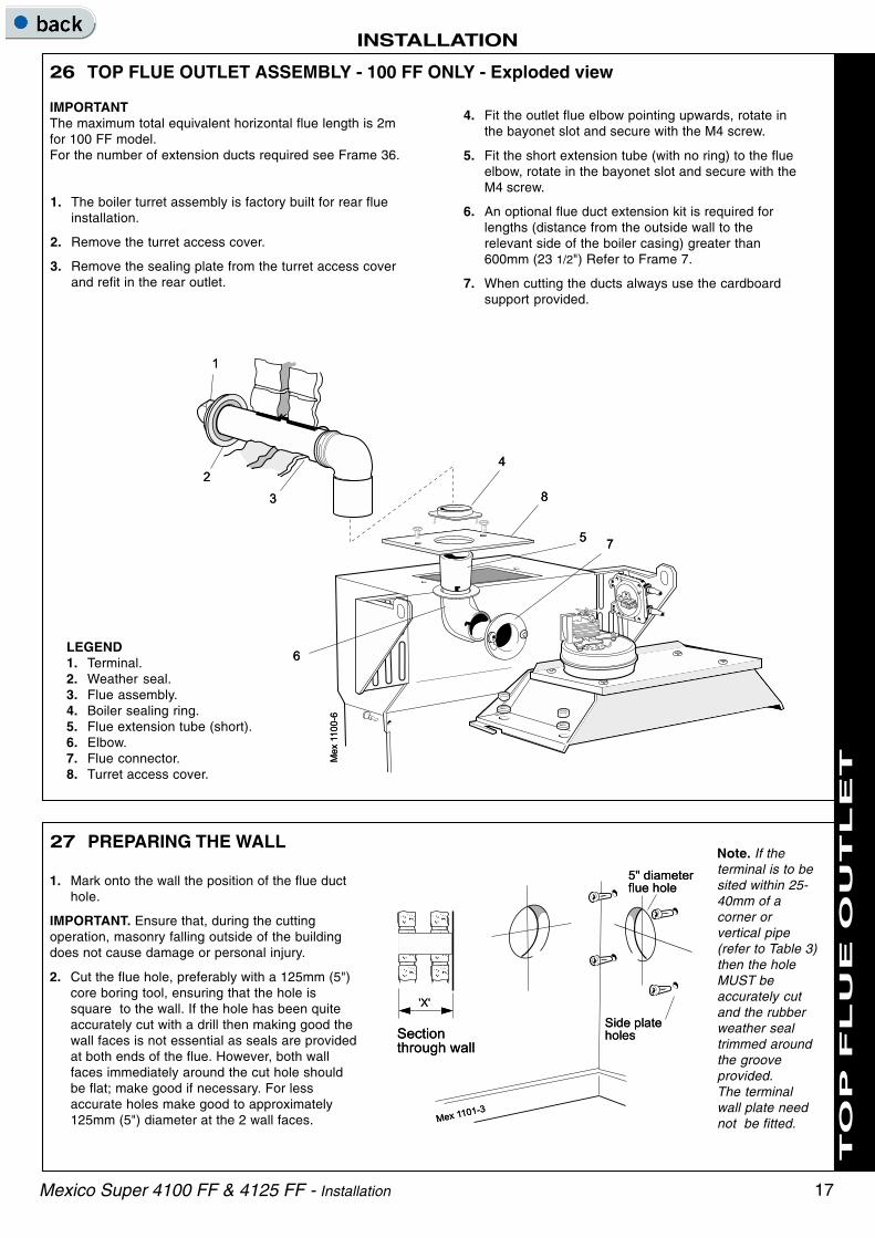
26 TOP FLUE OUTLET ASSEMBLY - 100 FF ONLY - Exploded view
1. The boiler turret assembly is factory built for rear flueinstallation.
2. Remove the turret access cover.
3. Remove the sealing plate from the turret access coverand refit in the rear outlet.
IMPORTANTThe maximum total equivalent horizontal flue length is 2mfor 100 FF model.For the number of extension ducts required see Frame 36.
LEGEND1. Terminal.2. Weather seal.3. Flue assembly.4. Boiler sealing ring.5. Flue extension tube (short).6. Elbow.7. Flue connector.8. Turret access cover.
4. Fit the outlet flue elbow pointing upwards, rotate inthe bayonet slot and secure with the M4 screw.
5. Fit the short extension tube (with no ring) to the flueelbow, rotate in the bayonet slot and secure with theM4 screw.
6. An optional flue duct extension kit is required forlengths (distance from the outside wall to therelevant side of the boiler casing) greater than600mm (23 1/2") Refer to Frame 7.
7. When cutting the ducts always use the cardboardsupport provided.
27 PREPARING THE WALL
1. Mark onto the wall the position of the flue ducthole.
IMPORTANT. Ensure that, during the cuttingoperation, masonry falling outside of the buildingdoes not cause damage or personal injury.
2. Cut the flue hole, preferably with a 125mm (5")core boring tool, ensuring that the hole issquare to the wall. If the hole has been quiteaccurately cut with a drill then making good thewall faces is not essential as seals are providedat both ends of the flue. However, both wallfaces immediately around the cut hole shouldbe flat; make good if necessary. For lessaccurate holes make good to approximately125mm (5") diameter at the 2 wall faces.
Note. If theterminal is to besited within 25-40mm of acorner orvertical pipe(refer to Table 3)then the holeMUST beaccurately cutand the rubberweather sealtrimmed aroundthe grooveprovided.The terminalwall plate neednot be fitted.

18
RE
AR
FL
UE
OU
TL
ET
INSTALLATIONT
OP
FL
UE
OU
TL
ET
Mexico Super 4100 FF & 4125 FF - Installation
28 CUTTING THE FLUE - wall thicknesses of 114 to 600mm
1. Measure and note the wall thickness X.
2. Mark the wall thickness onto the flue.
3. To ensure the tube is cut square, mark the flue all theway round.
4. Cut to length X, using the cardboard ring for support.
5. Remove cardboard ring and remove any burrs.
29 FITTING BOILER SEALING RING TO THE FLUE
1. Fit the boiler sealing ring inside the appropriate length(A) of outer flue duct (refer to Frame 7). Ensure theboiler sealing ring is fully engaged.
2. Drill 3 holes 3.2mm (1/8") dia. through the outer flue ductand boiler sealing ring. Do not drill the inner flue duct.
3. Insert the self tapping screws, provided, in order to fixthe boiler sealing ring in position.
4. Fit the turret access cover to the sealing ring.
1. To determine the position for thefoam seal measure the wallthickness and mark it onto the flue,measuring from the groove near theterminal.
2. Wrap the self-adhesive foam stripround the flue, ensuring that thefoam is on the terminal side of theline. This seals the gap between theflue and the wall.
30 FITTING THE FOAM SEAL

19
INSTALLATION
TO
P F
LU
E O
UT
LE
T
Mexico Super 4100 FF & 4125 FF - Installation
31 FITTING THE FLUE ASSEMBLYInside fitting.
1. Insert the flue assembly through the hole far enough toallow the rubber seal to unfold completely and form anadequate seal on the outside wall.
2. Ensure the notch is at the top.
32 FITTING THE SIDE OUTLET PLATES
Note. If the boiler is fitted closer than 25mm to the side wallthe side outlet plate must be fitted now.
1. Split the side outlet plate into 2 down the split line.
2. Fit the 2 halves of the side outlet plate to the wall,ensuring they are behind the boiler sealing ring.
33 LOCATING THE BOILERPosition the boiler beneath the flue assembly.
1. Connect the flue terminal to the boiler,using the length (A) of flue ductpreviously cut and ensuring that theinner flue locates into the shortextension tube.
2. Secure the flue to the boiler using the 2M4 x 16mm screws previouslyremoved.
34 CONNECTING THE FLUE TO THE BOILER
20
INSTALLATIONT
OP
R
EA
R &
S
ID
E F
LU
E O
UT
LE
T
Mexico Super 4100 FF & 4125 FF - Installation
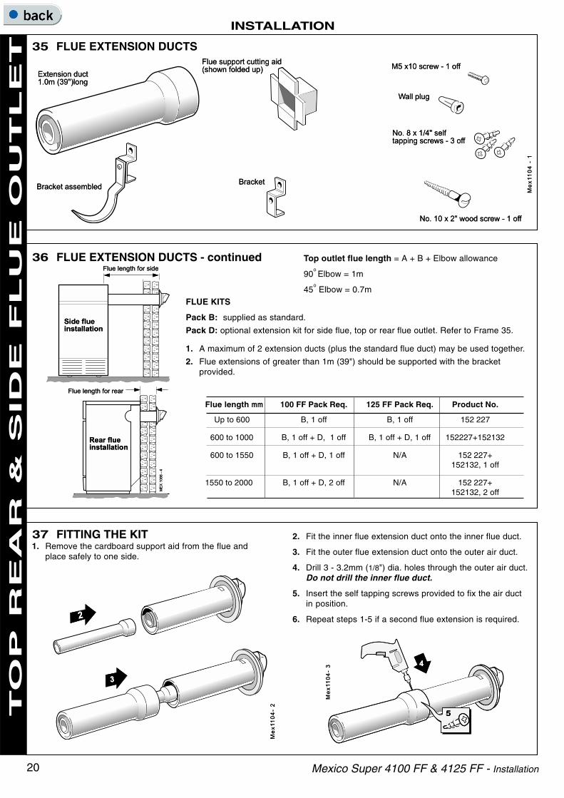
36 FLUE EXTENSION DUCTS - continued
FLUE KITS
Pack B: supplied as standard.
Pack D: optional extension kit for side flue, top or rear flue outlet. Refer to Frame 35.
1. A maximum of 2 extension ducts (plus the standard flue duct) may be used together.
2. Flue extensions of greater than 1m (39") should be supported with the bracketprovided.
35 FLUE EXTENSION DUCTS
Flue length mm 100 FF Pack Req. 125 FF Pack Req. Product No.
Up to 600 B, 1 off B, 1 off 152 227
600 to 1000 B, 1 off + D, 1 off B, 1 off + D, 1 off 152227+152132
600 to 1550 B, 1 off + D, 1 off N/A 152 227+152132, 1 off
1550 to 2000 B, 1 off + D, 2 off N/A 152 227+152132, 2 off
Top outlet flue length = A + B + Elbow allowance
90o Elbow = 1m
45o Elbow = 0.7m
37 FITTING THE KIT1. Remove the cardboard support aid from the flue and
place safely to one side.
2. Fit the inner flue extension duct onto the inner flue duct.
3. Fit the outer flue extension duct onto the outer air duct.
4. Drill 3 - 3.2mm (1/8") dia. holes through the outer air duct.Do not drill the inner flue duct.
5. Insert the self tapping screws provided to fix the air ductin position.
6. Repeat steps 1-5 if a second flue extension is required.

21Mexico Super 4100 FF & 4125 FF - Installation
INSTALLATION
21
2. Ensure that all valves are open. Fill and vent the systemand check for water soundness.
Notes.a. Isolating valves must be fitted as close to the pump
as possible.
b. The boiler is not suitable for a sealed system unlessthe overheat thermostat kit is installed.
c. The boiler is not suitable for use with a direct hotwater cylinder.
40 WATER CONNECTIONS1. Connect the system flow and return pipework to the
boiler as appropriate. Refer to Frames 41 and 42 forguidance on system design.
Notes.
When the required output exceeds 14.4 kW(49 000 Btu/h) then 28mm (1") pumped flow and returnpipes should be used, both to and from the boiler.
Gravity connections MUST be at least 28mm (1").
39 GAS CONNECTION
1. A MINIMUM working gaspressure of 20 mbar (8in.w.g.) MUST be availableat the boiler inlet, with theboiler operating.
2. Extend a gas supply pipeNOT LESS THAN 15mm(1/2") OD to the boiler andconnect to the gas cocksituated at the front LH sideof the boiler.
3. Test the gas installation forsoundness and purge inaccordance with BS.6891:1988. Refer to Frame 52.
Boiler Dimension A
4100 FF 327 (12 7/8")
4125 FF 400 (15 3/4")
38 TERMINAL WALL PLATE
This plate allows neat concealment and full compression ofthe rubber seal. Its use is not essential if the flue hole andflue ducts have been accurately cut and the outside wallface is flat.
1. Position the terminal wall plate over the terminal.
2. Mark and drill 4 fixing holes with an 7mm (9/32") masonrydrill.
3. Insert the 4 plastic plugs provided.
4. Secure the plate with 4 of the No.10 x 2" screwsprovided.
Note. If the terminal is less than 2m (6' 6") above groundlevel, an approved terminal guard should be fitted. Refer tothe Contents List on Page 3.
INS
TA
LL
AT
ION

22 Mexico Super 4100 FF & 4125 FF - Installation
INSTALLATION
Notes.a. Flow and return pipes should rise vertically on leaving the
boiler.b. Horizontal pipes should be ABOVE ceiling level and as short
as possible.c. A MINIMUM inclination of 25 mm per 3 m run (1" per 10') is
required to avoid air locks.
If the above conditions cannot be met pumped primaries shouldbe used.
1. Separate flow and return connections are used for eachservice. All possible configurations are given in Frame 8 andONLY those shown should be used.
2. The schematic pipework graph is based on the assumptionthat NO MORE than 8 elbows are used in the gravity loop,including entry to the boiler.
3. For each extra elbow in excess of 8 (R) MUST be reduced by300 mm (12") or (H) increased by 100 mm (4")
4. Whatever value is selected for (R), the value of (H) MUST beat least that indicated by the graph.
(R) = the horizontal distance between the centre line of thecylinder and the boiler tappings used - measured alongthe pipe run.
(H) = the vertical distance between the top of the boiler andthe base of the cylinder.
41 MINIMUM REQUIREMENTS Fully pumped systems
1. Open vent and cold feed connections must be made to the boilerflow and return tappings according to the options shown in Frame8.
2. The boiler is assumed to be the highest point of thecirculating system.
3. The circulating pump is positioned on the FLOW andthe vertical distance, between the pump and feed/expansion tank, must comply with the pumpmanufacturer's minimum requirements, to avoidcavitation. Should these conditions not apply, eitherlower the pump position or raise the feed/ expansiontank above the minimum requirements of CaradonIdeal Ltd.
4. The water velocity through the boiler flow / return pipesis assumed to be below 1 m/s (3 ft./s), whilst the pumpflow rate is set to provide a temperature difference of11
oC (20
oF) across the boiler flow / return, at design
input.
5. This information is intended as a GUlDE ONLY andcannot take into account instantaneous changes inhead caused by the operation of motorised valves,pumps etc.
Due allowance MUST be made if surging is liable tooccur.
If in any doubt, contact Caradon Ideal Ltd.
42 GRAVITY HOT WATER & PUMPED CENTRAL HEATING
INS
TA
LL
AT
ION

23Mexico Super 4100 FF & 4125 FF - Installation
INSTALLATION
WARNING
The appliance MUST be efficiently earthed.
A mains supply of 230 V ~ 50 Hz is required.
The fuse rating should be 3A.
All external controls and wiring MUST be suitable for mainsvoltage.
Wiring should be in 3-core PVC insulated cable NOT LESSthan 0.75 mm2 (24 x 0.2 mm) to BS.6500, Table 16.
Wiring external to the boiler MUST be in accordance withcurrent l.E.E. (BS.7671) Wiring Regulations and localregulations. For Ireland reference should be made to thecurrent ETCI rules for electrical installations.
43 ELECTRICAL CONNECTIONS
Connection must be made in a way that allows completeisolation of the electrical supply - such as a double poleswitch, having a 3mm (1/8") contact separation in bothpoles, or a plug and socket serving only the boiler andsystem controls.
The means of isolation must be accessible to the user afterinstallation.
This connection should be readily accessible and be madeadjacent to the boiler (except in the case of bathroominstallations for domestic boilers where the point ofconnection to the mains MUST be outside of the bathroom.)
44 INTERNAL WIRING
Flow and pictorial wiring diagrams are shown inFrames 45 and 46.
1. Remove the securing screw and lift off thecontrol box cover.
2. Route the electrical leads into the box and wireinto the terminal strip, as shown.
Notes.a. Secure each lead with one of the cable clamps.
b. The mains lead connection MUST be made sothat, should the lead slip from its anchorage, thecurrent conductors become taut before theearthing conductor.
45 EXTERNAL CONTROLSExternal wiring must be in accordance with the current I.E.E.(BS 7671) Wiring Regulations. Fore Ireland reference shouldbe made to the current ETCI rule for electrical installations.The wiring diagrams illustrated in Frames 47-49 cover thesystems most likely to be fitted to this appliance.For wiring external controls to the Mexico Super FF boilerreference should be made to the system wiring diagramssupplied by the relevant manufacturer, in conjunction with theflow wiring diagram below and also Frame 46.Difficulty in wiring should not arise, providing the followingdirections are observed:1. Controls that switch the system ON and OFF, e.g. a time
switch, MUST be wired, in series, in the live mains lead tothe boiler.
2. Controls that override an on/off control, e.g. a frostthermostat, MUST be wired into the mains lead, in parallel,with the control(s) to be overridden. Refer to Frame 50.
3. If a proprietary system is used, follow the instructionssupplied by the manufacturer.
Advice on required modifications to the wiring may beobtained from the component manufacturers.Note. If there are no external controls the circulating pumpMUST be wired into the control box.
LEGENDb bluebk blackbr browngy greyor orange
p pinkr redv violetw whitey/g yellow/green
INS
TA
LL
AT
ION

24 Mexico Super 4100 FF & 4125 FF - Installation
INSTALLATION
46 PICTORIAL WIRING
LEGEND
w white
r red
bk black
br brown
p purple
b blue
gy grey
y/g yellow/green
INS
TA
LL
AT
ION

25Mexico Super 4100 FF & 4125 FF - Installation
INSTALLATION
47 MID POSITION VALVE
Notes.
1. Some earth wires are omitted for clarity. Ensure properearth continuity when wiring.
2. Numbering of terminals on thermostats is specific to themanufacturer indicated.
3. This is a fully controlled system - set the boilerthermostat to maximum.
4. 'Switchmaster Midi' is similar in operation but the wiringdiffers slightly; see manufacturer's literature.
Pumped only
48 TWO SPRING CLOSED VALVES
Notes.
1. Some earth wires are omitted for clarity. Ensure proper earthcontinuity when wiring.
2. Numbering of terminals on thermostats is specific to themanufacturer.
3. This is a fully controlled system - set the boiler thermostat tomaximum.
4. 'Switchmaster Autozone' has grey and orange auxiliaryswitch leads but the GREY (NOT the orange) wire must beconnected to the incoming live supply.
Pumped only
49 HONEYWELL 'C' PLAN
Notes.
1. Some earth wires are omitted for clarity. Ensureproper earth continuity when wiring
2. Numbering of terminals on thermostats is specificto the manufacturer.
Gravity HW & Pumped CH
LEGEND
b blue
bk black
br brown
gy grey
or orange
p pink
r red
v violet
w white
y/g yellow/green
LEGEND
b blue
bk black
br brown
gy grey
or orange
p pink
r red
v violet
w white
y/g yellow/green
LEGEND
b blue
bk black
br brown
gy grey
or orange
p pink
r red
v violet
w white
y/g yellow/green
INS
TA
LL
AT
ION

26 Mexico Super 4100 FF & 4125 FF - Installation
INSTALLATION
50 FROST PROTECTION
Diagram A shows a double pole frost thermostat, which should sufficefor all systems which do not use the OFF terminals of the programmer.
Diagram B shows a 'change-over' frost thermostat, which will covermost systems which do use CH OFF. If, however, on such a systemthe HW pipework is in an isolated part of the house, a second frostthermostat may be used to protect it.
If in doubt, ask your installer for advice.
51 FITTING THE CASING
7. Insert the thermostat phial and phialretaining clip into the thermostat pocket.Take care not to kink the thermostatcapillary as it is unwound and secure itwith the split pin as shown.
8. Refit the in-line electrical connectorbetween the control box and the PCBbox.
9. Refit the grille assembly.
Central heating systems fitted wholly inside the housedo not normally require frost protection as the houseacts as a 'storage heater' and can normally be left atleast 24 hrs. without frost damage. However, if partsof the pipework run outside the house or if the boilerwill be left off for more than a day or so then a frost'stat should be wired into the system.
This is usually done at the programmer, in which casethe programme selector switches are set to OFF andall other controls MUST be left in the running position.
The frost 'stat should be sited in a cold place but whereit can sense heat from the system.
Wiring should be as shown, with minimal disturbanceto other wiring of the programmer.
Designation of the terminals will vary, but theprogrammer and thermostat manufacturer's leafletswill give full details.
1. Offer up the RH side panel, locating it with the pegin the baseplate, and push the panel back engagingit into the collector hood tab.
2. Secure the panel to the baseplate and turret frontpanel.
3. Repeat steps 1 and 2 to refit the LH side panel.
4. Place the top panel and push back.
5. Secure the top panel to the side panels.
IMPORTANT. Wiring within the boiler casing must beneatly secured with the cable straps provided andMUST NOT be allowed to touch the fan coolingimpellor, the burner front plate, or the cleanout coverand the collector hood.
6. Replace the control box cover and refit the controlpanel using the screws previously removed.
INS
TA
LL
AT
ION

27Mexico Super 4100 FF & 4125 FF - Installation
INSTALLATION
53 INITIAL LIGHTING
TO LIGHT THE BOILER
1. Check that all the drain cocks are closed and any valves inthe flow and return are open.
2. Check that the gas service cock (E) is OPEN and the boilermains on/off switch is OFF.
3. Slacken the screw in the burner pressure test point (B) andconnect a gas pressure gauge via a flexible tube.
4. Switch the electricity supply ON and check that all externalcontrols are calling for heat.
5. Set the boiler thermostat knob (G) to position 6. The fan willstart. After the fan has run for a few seconds the pilot solenoidvalve should open and the intermittent spark commence,continuing until the pilot is established. The main burner willthen cross-light smoothly. If this sequence does not occur,refer to the Fault Finding section.
6. Test for gas soundness around ALL boiler gas componentsusing leak detection fluid.
7. Operate the boiler for 10 minutes to stabilise the burnertemperature.
8. The boiler is preset at the factory to its nominal rating.Refer to Table 2 (page 2). If adjustment is necessaryremove the sealing cap and turn the adjusting screwclockwise to increase/anticlockwise to decrease thepressure until the required burner pressure is achieved.Refit the sealing cap.
9. Set the boiler mains on/off switch to OFF.
10. Remove the pressure gauge and tube. Retighten thesealing screw in the pressure test point.
11. Turn ON and check for gas soundness at the pressuretest point.
12. Refit the lower front panel and secure with the 2 fixingscrews.
52 COMMISSIONING AND TESTING
WARNING. Whilst effecting the required gas soundness test and purging air from the gas installation,open all windows and doors, extinguish naked lights and DO NOT SMOKE.
A. ELECTRICAL INSTALLATION
1. Checks to ensure electrical safety should be carriedout by a competent person.
2. ALWAYS carry out preliminary electrical systemchecks, i.e. earth continuity, polarity, resistance toearth and short circuit using a suitable test meter.
B. GAS INSTALLATION1. The whole of the gas installation, including the meter,
MUST be inspected and tested for soundness, and purgedin accordance with the recommendations of BS. 6891.In IE refer to I.S.813:2002.
2. Purging air from the gas installation may be expedited byloosening the union on the gas service cock on the boilerand purging until gas is detected.
3. Retighten the union and check for gas soundness.
LEGEND
A. Gas control valve.
B. Burner pressure test point.
C. Main burner pressureadjuster.
D. Inlet pressure test point.
E. Gas service cock.
F. Sightglass.
G. Boiler thermostat knob.
H. Main burner 'On' neon.
J. Overheat thermostat resetbutton (optional).
The Benchmark Log Book or equivalent self certification should be completed and signed to demonstrate compliancewith Building Regulations.
INS
TA
LL
AT
ION

28 Mexico Super 4100 FF & 4125 FF - Installation
INSTALLATION
54 GENERAL CHECKS
Make the following checks for correct operation:
1. Turn the boiler thermostat OFF and ON to check that themain burner is extinguished and relit in response.
2. Set the boiler thermostat knob to position 6 and operatethe mains on/off switch. Check that the main burner lightsand extinguishes in response.
3. Check that the programmer, if fitted, and all other systemcontrols function correctly.
Operate each control separately and check that the mainburner or circulating pump (as the case may be)responds.
4. Water circulation System
a. With the system HOT, examine all water connectionsfor soundness.
b. With the system still hot, turn off the gas, water andelectricity supplies to the boiler and drain down, inorder to complete the flushing process.
c. Refill and vent the system, clear all air locks and againcheck for water soundness.
d. Balance the system.
5. Finally, set the controls to the user's requirements, refitthe lower front panel securing with the 2 fixing screws andclose the controls door.
1. Hand the User's Instructions to the householder andexplain his or her responsibilities under current GasSafety (Installation and Use) Regulations or rules in force.
2. Draw attention to the lighting instruction label affixed tothe inside of the controls door.
3. Explain and demonstrate the lighting and shutting downprocedures.
4. The operation of the boiler and the use and adjustment ofALL system controls should be fully explained to thehouseholder, to ensure the greatest possible fueleconomy consistent with household requirements of bothheating and hot water consumption.
Advise the User of the precautions necessary to preventdamage to the system and to the building in the event ofthe system remaining inoperative during frosty conditions.
Notes.
!!!!! If an optional programmer kit is fittedrefer to the separate Programmer KitInstallation Instructions and ProgrammerUser's Instructions.
!!!!! The temperatures quoted are approximateand vary between installations.
55 HANDING OVER
After completing the installation and commissioning of the system theinstaller should hand over to the householder by the following actions:
5. Explain the function and the use of the boiler thermostatand external controls.
6. Explain and demonstrate the function of time andtemperature controls, radiator valves etc., for theeconomic use of the system.
7. If an optional Programmer Kit is fitted then draw attentionto the Programmer User's Instructions and hand them tothe householder.
After installation, commissioning, and customer
hand-over please complete the appliance log book and leave this with the customer.For IE, it is necessary to complete a "Declaration ofConformity" to indicate compliance to I.S. 813:2002.
8. Stress the importance of regular servicing by a CORGIregistered installer and that a comprehensive serviceshould be carried out AT LEAST ONCE A YEAR. In IEservicing work must be carried out by a CompetentPerson.
Thermostat Flow TemperatureKnob Setting
oC
oF
2 60 140
3 66 150
4 71 160
5 77 170
6 82 180
WARNING. The boiler must not be operated with the casing removed.
INS
TA
LL
AT
ION

29
SERVICING
Mexico Super 4100 FF & 4125 FF - Installation
56 SCHEDULEWARNING.BEFORE SERVICING always turn OFF the gas supply atthe gas service cock and switch OFF and DISCONNECTthe electrical supply to the appliance.
To ensure the continued safe and efficient operation of theappliance it is recommended that it is checked at regularintervals and serviced as necessary. The frequency ofservicing will depend upon the installation condition andusage but should be carried out at least annually .
It is the law that any service work must be carried out by aCORGI registered installer. In IE servicing work must becarried out by a Competent Person.
a. Light the boiler and carry out a pre-service check, notingany operational faults.
b. Operate the boiler for at least 20 minutes. Check the gasconsumption.
c. Connect a suitable gas analyser to the sampling point onthe flue collector. Refer to Frame 60.
For correct operation the CO/CO2 content of the flue gasshould not be greater than 0.004 ratio. If this is the caseand the gas input is within 95% of the nominal then nofurther action need be taken. If not the case, proceed tostep (d).
d. Clean the main burner.
e. Clean the heat exchanger.
f. Clean the main injectors.
g. Check that the flue terminal is unobstructed and that theflue system is sealed correctly.
h. If the appliance has been installed in a compartment,check that the ventilation areas are clear. a. Light theboiler and carry out a pre-service check, noting anyoperational faults.
The servicing procedures are covered more fully in Frames58 to 62 and MUST be carried out in sequence.
Note.In order to carry out either servicing or replacement ofcomponents, the boiler casing must removed. Refer toFrame 57.
IMPORTANT. After completing the servicing or exchange ofcomponents always test for gas soundness and carry outfunctional checks as appropriate.When the work is complete the casing MUST be correctlyrefitted and secured.The boiler must NOT be operated if the casing is not fitted.
57 BOILER CASING REMOVAL1. Remove the 2 screws and lift off the lower front panel.
2. Remove the 2 screws and lift off the grille assembly.
3. Disconnect the electrical leads from the gas valve.
4. Disconnect the in-line connector on the PCB box lead.
5. Remove the thermostat phialfrom the pocket as shown.
6. Remove the 2 screws securingthe control panel and pull downto release the tabs from underthe top panel.
7. If the boiler is not fitted under awork top, access for fluecleaning will be improved byremoving the top panel.
SE
RV
ICIN
G

30
SERVICING
Mexico Super 4100 FF & 4125 FF - Installation
58 BURNER AND CONTROLS ASSEMBLY REMOVAL
1. Remove the silicon rubber tube from the fan sensingpoint.
2. Disconnect the fan leads.
3. Remove the M4 screw securing the flue connector to thefan.
4. Slacken the M4 screw securing the flue connector to theturret front panel.
5. Disconnect the silicon rubber tube from the top of thecollector hood.
6. Remove the 4 M4 screws on the top of the collector hoodand by sliding it forwards remove collector hood/fanassembly.
7. Check that the fan impellor runs freely. Remove anydebris from the impellor with a soft brush.
8. Remove the flue baffles.
9. Remove all loose deposits from the heat exchanger,particularly between the fins, using a suitable brush.
10. Re-assemble in reverse order. Lubricate fan 'O' ring withsilicon grease. Ensure the fan leads and 2 sensing tubesare connected.
59 CLEANING THE BURNER / PILOT ASSEMBLY
1. Brush off any deposits that may have fallen onto theburner head (ensuring that the flame ports areunobstructed) and remove any debris that may havecollected.
Note. Brushes with metallic bristles MUST NOT beused.
2. Remove the main burner injector .Check, clean orreplace, as required.
3. Refit the injector, using an approved jointing compound.
4. Inspect the pilot burner and ignition/detection electrode;ensure they are clear and in good condition.
Check that:
a. The pilot burner is clean and unobstructed.
b. The ignition/detection electrode is clean andundamaged.
c. The ignition/detection lead is in good condition andsecurely connected.
d. The spark gap is correct. Refer to Frame 69.
e. The position of the ignition/detection electrode relativeto the pilot burner is correct. Refer to Frame 69.
5. Clean or renew components as necessary.
60 CLEANING THE FAN/FLUEWAYS
1. Remove the 2 screws and lift off the lowerfront panel. Refer to Frame 57.
2. Remove the grilleassembly. Undo the gascock union.
3. Disconnect the ignitionlead from the PCB.
4. Remove the 4 wing nutsand withdraw the burnerand controls assembly,complete, from the boiler.
5. Place on a convenientworking surface.
SE
RV
ICIN
G

31
SERVICING
Mexico Super 4100 FF & 4125 FF - Installation
2. Main Burner Pressure
After servicing, reference should be made to Table 1,which quotes details of the output with the relatedburner pressure and heat input. Any requiredadjustments should be made using the pressureadjustment screw. Refer to Frame 53 - Initial Lighting.
Refit the lower front panel and secure with the 2 fixingscrews.
REPLACEMENT OF PARTS
63 GENERAL
When replacing any component:
1. Isolate the electricity supply.
2. Turn OFF the gas supply.
3. Remove the lower front panel and grille assembly.
Note. In order to assist fault finding, the control box printedcircuit board is fitted with 2 indicator lights which representthe following boiler conditions:
Neon I3. Mains electricity ON.
Neon SG1. Flashes to indicate ignition operation (stopsafter detection).
1. Unfasten the 2 M5 hexagon nuts and washers.Remove the assembly from the front plate.
2. Fit the new sightglass and re-assemble, asshown.
3. Retighten the 2 M5 hexagon nuts to ensure anairtight seal. Do NOT overtighten.
61 RE-ASSEMBLY
62 GAS PRESSURE ADJUSTMENT
1. Pilot Pressure
Pilot adjustment is factory set to maximum and noadjustment is possible.
64 SIGHTGLASS REPLACEMENT
Re-assemble the boiler in the following order:
1. Refit the flue baffles.
2. Inspect the collector hood rope gasket and replace, ifnecessary, ensuring that the self adhesive rope is fittedcentrally on to the lip of the collector hood / fan assembly.The boiler efficiency will be adversely affected if incorrectlyfitted. Refit the collector hood cover with the 4 screws.Tighten the screws. Ensure that the sealing gasket iscompressed. Refit the pressure pipe.
3. Refit the positive pressure tubes on the top of the fanhousing. Reconnect the electrical leads.
4. Refit the burner assembly.
5. Reconnect the gas supply and the electrical wiring.Refer to Frames 39 & 48.
7. Check for gas soundness. Check the gas servicecock and pressure test point.
8. Refit the boiler casing (Refer to Frame 51).
9. Refit the lower front panel and secure with the 2fixing screws.
The boiler MUST NOT be operated if the casing is not fitted.
SE
RV
ICIN
G

32
SERVICING
Mexico Super 4100 FF & 4125 FF - Installation
65 PILOT BURNER REPLACEMENT
1. Remove the 2 screws and lift off the lower frontpanel then remove the grille assembly. Refer toFrame 57.Undo the gas cock union. Remove the 4 wing nutsand withdraw the burner and controls assembly,complete, from the boiler.
2. Disconnect the ignition lead from the PCB.
3. Prise the retaining clip out of the groove in the
electrode, using a small screwdriver, and withdrawthe electrode. Refer to Frame 69.
4. Undo the pilot supply pipe connection and ease
clear of the pilot burner. DO NOT lose the pilotinjector, which is a push-fit in the pilot burnerhousing.
5. Remove the 2 securing screws and washers, andwithdraw the pilot burner.
6. Fit the new pilot burner and re-assemble inreverse order, ensuring that:
a. The injector is in position when refitting the pilotsupply.
b. A gas-tight joint is made.
c. The spark gap is correct. Refer to Frame 69.
1. Remove the 2 screws and liftoff the lower front panel.Refer to Frame 57.
2. Pull off the thermostat knob.
3. Remove the 2 screws andpull down the control paneltabs clear of the top panel.
4. Remove the thermostat phialfrom the pocket. Refer toFrame 57.
5. Remove the bottom screwand remove the cover.
6. Remove the top screw andease the control box off thecontrol panel.
7. Remove the 2 screws torelease the thermostatbracket.
8. Disconnect the electricalleads.
9. Unscrew the thermostat nut towithdraw the thermostat.
10. Fit the new thermostat and re-assemble in reverse order.
66 CONTROL THERMOSTAT REPLACEMENT
SE
RV
ICIN
G

33
SERVICING
Mexico Super 4100 FF & 4125 FF - Installation
13. Replace the lower front panel and secure with the 2 fixingscrews.
14. Check the operation of the boiler.
67 CONTROLS PANEL REPLACEMENT1. Remove the 2 screws and lift off the lower
front panel. Refer to Frame 57.
2. Pull off the thermostat knob.
3. Disconnect the in-line electricalconnector between the control box andPCB box.
4. Unscrew the 2 screws and pull downthe control panel so that the 2 tabsclear the top panel.
5. Remove the thermostat phial from thepocket. Refer to Frame 57.
6. Remove the bottom screw and removethe cover from the control box.
7. Remove the top screw and ease thecontrol box off the control panel.
8. Disconnect the mains electrical supplyfrom the terminal strip and release fromits clamp.
9. Assemble new control box and paneland fit to the casing in reverse order.
10. Insert control thermostat phial intopocket and secure with the split pin.
11. Refit the in-line electrical connectorbetween the control box and the PCBbox.
12. Remove control box cover and make electrical supplyconnections to the terminal strip. Refer to Frame 46.
1. Remove the 2 screws and lift off the lower frontpanel. Refer to Frame 57.
2. Slacken the screw at the thermostat pocket andwithdraw the phial from the pocket.
3. Remove the thermostat retaining nut and withdrawthe thermostat from the control panel.
4. Transfer the electrical leads from the oldthermostat to the replacement (polarity is notimportant).
5. Fit the new thermostat ensuring that the alignmentpeg on the thermostat sits in the small holeadjacent to the main fixing hole and reassemble inreverse order.
6. Replace the lower front panel and secure with the2 fixing screws.
7. Check the operation of the boiler.
4
68 OVERHEAT THERMOSTAT REPLACEMENT (if fitted)
13. Replace the lower front panel and secure withthe 2 fixing screws.
14. Check the operation of the boiler.
SE
RV
ICIN
G

34
SERVICING
Mexico Super 4100 FF & 4125 FF - Installation
69 IGNITION ELECTRODE AND LEAD REPLACEMENT
1. Remove the 2 screws and lift off the lower frontpanel then remove the grille assembly. Refer toFrame 57.Undo the gas cock union. Remove the 4 wing nutsand withdraw the burner and controls assembly,complete, from the boiler.
7
4
70 MAIN BURNER REPLACEMENT
Detail of pilot flame length and spark gap
1. Remove the 2 screws and lift off the lower front panelthen remove the grille assembly. Refer to Frame 57.Undo the gas cock union. Remove the 4 wing nuts andwithdraw the burner and controls assembly, complete,from the boiler.
2. Disconnect the ignition lead from the PCB.
3. Prise the retaining clip out of the groove in theelectrode, using a small screwdriver, and withdraw theelectrode.
4. Push in the new electrode untilthe retaining clip locates in thegroove and re-assemble inreverse order.
2. Disconnect theignition lead fromthe PCB.
3. Remove the 2screws securing thepilot burner and pullthe assembly clearof the main burner.
4. Remove the 2 nutsand washerssecuring the burnerto the front plateand manifold.Withdraw theburner.
5. Fit the new burnerand re-assemble inreverse order,taking care not todamage the mainburner injectorwhich is screwedinto the burnermanifold.
SE
RV
ICIN
G

35
SERVICING
Mexico Super 4100 FF & 4125 FF - Installation
1. Remove the 2 screws and lift off the lowerfront panel then remove the grille assembly.Refer to Frame 57.Undo the gas cock union. Remove the 4 wingnuts and withdraw the burner and controlsassembly, complete, from the boiler.
2. Disconnect the ignition lead from the PCB.
3. Undo the pilot supply connection.
4. Undo the manifold securing nuts and removethe manifold from the front plate.
5. Unscrew the burner injector from themanifold.
6. Fit the new injector, using an approvedjointing compound, and re-assemble inreverse order.
71 MAIN BURNER INJECTOR REPLACEMENT
1. Remove the 2 screws and lift off the lower front panel thenremove the grille assembly. Refer to Frame 57.Undo the gas cock union. Remove the 4 wing nuts andwithdraw the burner and controls assembly, complete,from the boiler.
2. Disconnect the ignition lead from the PCB.
3. Undo the pilot supply connection.
4. Unscrew the gas inlet pipe from the valve.
72 GAS VALVE REPLACEMENT
5. Remove the 4 securing screws and withdraw the valvefrom the burner manifold.
6. Fit the new gas valve, ensuring that:
a. The valve is fitted the correct way round - an arrowengraved on the valve indicates the direction of flow.
b. The sealing 'O' ring supplied with the valve is correctlyfitted at the outlet flange.
c. An approved jointing compound is used whenreconnecting the gas inlet pipe.
SE
RV
ICIN
G

36
SERVICING
Mexico Super 4100 FF & 4125 FF - Installation
74 AIR PRESSURE SWITCH (APS) REPLACEMENT
1. Remove the lower front panel, control panel and top panel. Refer to Frame 57.
2. Remove the silicon rubber tube from the fan sensing point.
3. Disconnect the fan leads.
4. Remove the M4 screw securing the flue connector to the fan.
5. Slacken the 2 M4 screws securing the flue connector to the turret front panel.
6. Disconnect the silicon rubber tube from the top of the collector hood.
7. Remove the 4 M4 screws on the top of thecollector hood and by sliding it forwards removecollector hood / fan assembly.
8. Remove the three M4 screws retaining the fan tothe collector hood.
9. Re-assemble in reverse order. Lubricate fan 'O'ring with silicon grease. Ensure the fan leadsand 2 sensing tubes are connected.
10. Refit the boiler casing.
11. Check the boiler operation.
73 FAN REPLACEMENT
1. Remove the lower front panel, control panel andthe top panel. Refer to Frame 57.
2. Remove the APS fixing screw.
3. Remove both sensing tubes from the APS.
4. Remove the 3 electrical connections from theAPS.
5. Connect the new APS in reverse order.
6. Refit the APS with the fixing screw.
7. Refit the boiler casing.
8. Check the boiler operation.
75 PRINTED CIRCUIT BOARD (PCB) REPLACEMENT
1. Remove the 2 screws and lift off thelower front panel. Refer to Frame 57.
2. Undo the PCB cover fixing screw andremove the cover.
3. Remove the HT lead from the PCB
4. Remove the 6 push-in connectorsfrom the PCB.
5. Compress the barbs on the PCBstand-offs to release the PCB fromthe box
6. Fit the new PCB and re-assemble inreverse order.
7. Refit the boiler casing.
8. Check the operation of the boiler.
SE
RV
ICIN
G
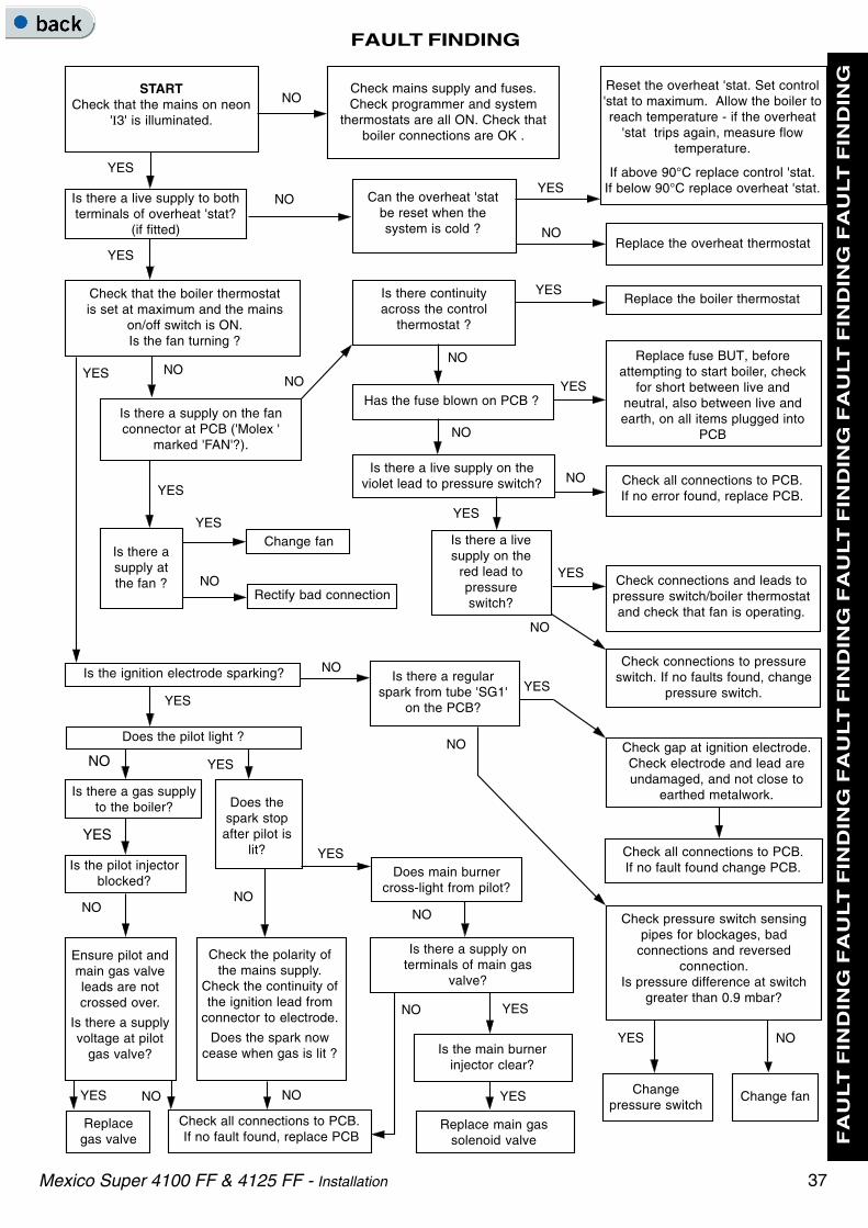
37
FAULT FINDING
F
AU
LT
FIN
DIN
G F
AU
LT
FIN
DIN
G F
AU
LT
FIN
DIN
G F
AU
LT
FIN
DIN
G F
AU
LT
FIN
DIN
G F
AU
LT
FIN
DIN
G
Mexico Super 4100 FF & 4125 FF - Installation
Check all connections to PCB. If no fault found, replace PCB
Reset the overheat 'stat. Set control'stat to maximum. Allow the boiler toreach temperature - if the overheat
'stat trips again, measure flowtemperature.
If above 90°C replace control 'stat.If below 90°C replace overheat 'stat.
STARTCheck that the mains on neon
'I3' is illuminated.
YES
NO
YES
YES
NO
Is there a live supply to bothterminals of overheat 'stat?
(if fitted)
Is the ignition electrode sparking?
YES
YES
YES
Change fanYES
NORectify bad connection
Check mains supply and fuses.Check programmer and system
thermostats are all ON. Check thatboiler connections are OK .
Check that the boiler thermostatis set at maximum and the mains
on/off switch is ON.Is the fan turning ?
Check connections to pressureswitch. If no faults found, change
pressure switch.
Replace the boiler thermostat
Check connections and leads topressure switch/boiler thermostatand check that fan is operating.
Check all connections to PCB.If no fault found change PCB.
YES
Check pressure switch sensingpipes for blockages, bad
connections and reversedconnection.
Is pressure difference at switchgreater than 0.9 mbar?
Change fan
YES NO
Changepressure switch
Does the pilot light ?
NO
YES
NO
YES
Does thespark stopafter pilot is
lit?
NO
Is there a gas supplyto the boiler?
Is the pilot injectorblocked?
YES
Replacegas valve
NO
Is there a supply onterminals of main gas
valve?
YESNO
YES
NONO
Is there a supply on the fanconnector at PCB ('Molex '
marked 'FAN'?).
YES
YES
NO
NO
Check the polarity ofthe mains supply.
Check the continuity ofthe ignition lead from
connector to electrode.
Does the spark nowcease when gas is lit ?
Ensure pilot andmain gas valveleads are notcrossed over.
Is there a supplyvoltage at pilot
gas valve?
Is there a livesupply on the
red lead topressureswitch?
NO
Is there a regularspark from tube 'SG1'
on the PCB?
Can the overheat 'statbe reset when thesystem is cold ?
NOYES
NO
Replace fuse BUT, beforeattempting to start boiler, check
for short between live andneutral, also between live andearth, on all items plugged into
PCB
Check all connections to PCB.If no error found, replace PCB.
Is there continuityacross the control
thermostat ?
YES NONO
YES
Has the fuse blown on PCB ?
NO
NO
Is there a live supply on theviolet lead to pressure switch?
Is there asupply atthe fan ?
Replace the overheat thermostat
Does main burnercross-light from pilot?
Is the main burnerinjector clear?
Replace main gassolenoid valve
Check gap at ignition electrode.Check electrode and lead areundamaged, and not close to
earthed metalwork.

38
SHORT LIST OF PARTS
Mexico Super 4100 FF & 4125 FF - Installation
The following are parts commonly required as replacementcomponents, due to damage or expendability. Their failure orabsence is likely to affect safety or performance of thisappliance.
The list is extracted from the British Gas List of Parts, whichcontains all available spare parts.
The full list is held by British Gas, Caradon Ideal Ltd.distributors and merchants.
When ordering spares please quote:
1. Boiler model
2. Appliance G.C. number
3. Description
4. Quantity
5. Product no.
Key No. G.C. Part No. Description Qty. Product No.
14 Fan assembly 4100/4125FF 1 079 889
17 319 494 Sightglass assembly 1 079 334
20 Main burner383 598 LH AEROMATIC No. AC 19/123 216; 4100 FF 1 012 959E01-372 RH AEROMATIC No. AC 19/123 299; 4100 FF 1 150 871
LH AEROMATIC No. AC 19/123 300; 4125 FF 1 153 203E01-374 RH AEROMATIC No. AC 19/123 298; 4125 FF 1 150 865
21 Main injector398 055 BRAY Cat. 010 - size 1400; 4100 FF 2 003 361E01-490 BRAY Cat. 103 - size 1700; 4125 FF 2 150 986
22 E01-505 Pilot burner / Injector / Fittings - HONEYWELL Q 385 A 2036; 1 075 291
23 381 656 Pilot injector - HONEYWELL 4500 4108 001 1 003 825
24 Gas valve assembly - VR 4601CA 1018 + 'O' ring 4100/4125FF 1 170 664
26 386 575 Ignition electrode -HONEYWELL 45900413-004 1 151 079
27 HT lead - 1100mm 4100/4125FF 1 130 918
30 PCB sub-assembly 1 170 665
38 Pressure switch - HONEYWELL C6065F1316B 1 155 412
49 Flue baffle kit 4100 FF 6 079 8904125 FF 4 079 890
66 Thermostat - RANCO K36-P1354 1 151 903
67 308 557 Thermostat knob 1 111 904
When replacing a part on this appliance, use only spare parts that you can be assured conform to the safety and performancespecification that we require. Do not use reconditioned or copy parts that have not been clearly authorised by Ideal Boilers.

39
SHORT LIST OF PARTS
Mexico Super 4100 FF & 4125 FF - Installation
76 SHORT PARTS
Mex
187
9

40
LIST OF PARTS
Mexico Super 4100 FF & 4125 FF - Installation
Legend
63. Control panel complete assembly
65. Control box assembly
66. Control thermostat
77 BOILER CONTROL PANEL - Exploded View
67. Control thermostat knob
71. Control front panel (door)
72. Magnetic strip

41
LIST OF PARTS
Mexico Super 4100 FF & 4125 FF - Installation
78 PCB BOX - Exploded View
Legend
29. PCB chassis assembly
30. PCB sub-assembly
34. PCB support.
37. PCB cover.

42
LIST OF PARTS
Mexico Super 4100 FF & 4125 FF - Installation
79 BURNER AND CONTROLS ASSEMBLY - Exploded View
Legend
16. Front plate assy.
17. Sightglass assy.
18. Burner manifold.
19. Pilot pipe.
20. Main burner.
21. Main injector.
22. Pilot burner.
24. Gas valve.
25. 'O' ring.
26. Ignition electrode.
27. Ignition lead.
28. Gas cock.
50. Sealing gasket.
51. Sealing plate.

43
LIST OF PARTS
Mexico Super 4100 FF & 4125 FF - Installation
Legend
46. Baseplate
62. Casing complete
63. Controls panel complete
71. Controls front panel (door)
73. Side panel - LH
74. Side panel - RH
75. Lower front panel
76. Top panel
77. Grille panel
80 BOILER CASING ASSEMBLY

Ideal Boilers, P.O. Box 103, National Ave, Kingston upon Hull,HU5 4JN. Telephone: 01482 492 251 Fax: 01482 448 858.Registration No. London 322 137.
March 2003 UIN 157 641 A04
Technical Training
Caradon Ideal Limited pursues a policy of continuingimprovement in the design and performance of its products. Theright is therefore reserved to vary specification without notice.
The Ideal Boilers Technical Training Centre offers a seriesof first class training courses for domestic, commercial andindustrial heating installers, engineers and systemspecifiers.For details of courses please ring: ............. 01482 498 432
THIS SYMBOL IS YOURASSURANCE OF QUALITY
These appliances are designed for use with NaturalGas only. They have been tested and conform with theprovisions of BS. 6332 and BS. 5258.
CERTIFIED PRODUCTManufactured under a BS EN ISO 9001:1994 Quality System accepted by BSI
The code of practice for the installation,commissioning & servicing of central heating systems
Ideal Installer/Technical Helpline: 01482 498663www.idealboilers.com