sun fire v120 and netra 120 user's server guide san antonio road palo alto, ca 94303 u.s.a....
TRANSCRIPT
Sun Microsystems, Inc.901 San Antonio RoadPalo Alto, CA 94303U.S.A. 650-960-1300
Send comments about this document to: [email protected]
Sun Fire™ V120 and Netra™ 120Server User’s Guide
Part No. 816-2090-10December 2001, Revision A

PleaseRecycle
Copyright 2001 Sun Microsystems, Inc., 901 San Antonio Road, Palo Alto, CA 94303-4900 U.S.A. All rights reserved.
This product or document is distributed under licenses restricting its use, copying, distribution, and decompilation. No part of this product or
document may be reproduced in any form by any means without prior written authorization of Sun and its licensors, if any. Third-party
software, including font technology, is copyrighted and licensed from Sun suppliers.
Parts of the product may be derived from Berkeley BSD systems, licensed from the University of California. UNIX is a registered trademark in
the U.S. and other countries, exclusively licensed through X/Open Company, Ltd.
Sun, Sun Microsystems, the Sun logo, AnswerBook2, docs.sun.com, Solaris, Sun Enterprise, OpenBoot, SunSolve, Sun Fire and Netra are
trademarks, registered trademarks, or service marks of Sun Microsystems, Inc. in the U.S. and other countries. All SPARC trademarks are used
under license and are trademarks or registered trademarks of SPARC International, Inc. in the U.S. and other countries. Products bearing
SPARC trademarks are based upon an architecture developed by Sun Microsystems, Inc.
The OPEN LOOK and Sun™ Graphical User Interface was developed by Sun Microsystems, Inc. for its users and licensees. Sun acknowledges
the pioneering efforts of Xerox in researching and developing the concept of visual or graphical user interfaces for the computer industry. Sun
holds a non-exclusive license from Xerox to the Xerox Graphical User Interface, which license also covers Sun’s licensees who implement OPEN
LOOK GUIs and otherwise comply with Sun’s written license agreements.
Federal Acquisitions: Commercial Software—Government Users Subject to Standard License Terms and Conditions.
DOCUMENTATION IS PROVIDED “AS IS” AND ALL EXPRESS OR IMPLIED CONDITIONS, REPRESENTATIONS AND WARRANTIES,
INCLUDING ANY IMPLIED WARRANTY OF MERCHANTABILITY, FITNESS FOR A PARTICULAR PURPOSE OR NON-INFRINGEMENT,
ARE DISCLAIMED, EXCEPT TO THE EXTENT THAT SUCH DISCLAIMERS ARE HELD TO BE LEGALLY INVALID.
Copyright 2001 Sun Microsystems, Inc., 901 San Antonio Road, Palo Alto, CA 94303-4900 Etats-Unis. Tous droits réservés.
Ce produit ou document est distribué avec des licences qui en restreignent l’utilisation, la copie, la distribution, et la décompilation. Aucune
partie de ce produit ou document ne peut être reproduite sous aucune forme, par quelque moyen que ce soit, sans l’autorisation préalable et
écrite de Sun et de ses bailleurs de licence, s’il y en a. Le logiciel détenu par des tiers, et qui comprend la technologie relative aux polices de
caractères, est protégé par un copyright et licencié par des fournisseurs de Sun.
Des parties de ce produit pourront être dérivées des systèmes Berkeley BSD licenciés par l’Université de Californie. UNIX est une marque
déposée aux Etats-Unis et dans d’autres pays et licenciée exclusivement par X/Open Company, Ltd.
Sun, Sun Microsystems, le logo Sun, AnswerBook2, docs.sun.com, Solaris, Sun Enterprise, OpenBoot, SunSolve, Sun Fire et Netra sont des
marques de fabrique ou des marques déposées, ou marques de service, de Sun Microsystems, Inc. aux Etats-Unis et dans d’autres pays. Toutes
les marques SPARC sont utilisées sous licence et sont des marques de fabrique ou des marques déposées de SPARC International, Inc. aux Etats-
Unis et dans d’autres pays. Les produits portant les marques SPARC sont basés sur une architecture développée par Sun Microsystems, Inc.
L’interface d’utilisation graphique OPEN LOOK et Sun™ a été développée par Sun Microsystems, Inc. pour ses utilisateurs et licenciés. Sun
reconnaît les efforts de pionniers de Xerox pour la recherche et le développement du concept des interfaces d’utilisation visuelle ou graphique
pour l’industrie de l’informatique. Sun détient une licence non exclusive de Xerox sur l’interface d’utilisation graphique Xerox, cette licence
couvrant également les licenciés de Sun qui mettent en place l’interface d’utilisation graphique OPEN LOOK et qui en outre se conforment aux
licences écrites de Sun.
LA DOCUMENTATION EST FOURNIE “EN L’ETAT” ET TOUTES AUTRES CONDITIONS, DECLARATIONS ET GARANTIES EXPRESSES
OU TACITES SONT FORMELLEMENT EXCLUES, DANS LA MESURE AUTORISEE PAR LA LOI APPLICABLE, Y COMPRIS NOTAMMENT
TOUTE GARANTIE IMPLICITE RELATIVE A LA QUALITE MARCHANDE, A L’APTITUDE A UNE UTILISATION PARTICULIERE OU A
L’ABSENCE DE CONTREFAÇON.

Contents
Part I Installation and Configuration
1. Introduction 1-1
1.1 Overview of the Sun Fire V120 and Netra 120 Servers 1-2
1.2 Contents of the Ship Kit 1-3
1.3 Optional Hardware and Software 1-5
1.4 Front Panel 1-6
1.5 Back Panel 1-7
1.6 The Fans Inside the Sun Fire V120 and Netra 120 Servers 1-8
1.7 Tools You Need for Installation 1-8
1.8 Environmental Specifications 1-9
1.8.1 Tolerance of Environmental Conditions 1-9
1.8.2 Acoustic Noise Generated by the Server 1-9
1.8.3 Environmental Compliance Information 1-9
1.9 Choosing Between a Rack and a Cabinet 1-10
2. Power and Cooling 2-1
2.1 Operating Power Limits and Ranges 2-2
2.2 Power Consumption 2-3
2.3 Estimating Heat Dissipation 2-4
Contents iii

3. Using DC Power 3-1
3.1 Grounding the Netra 120 Server 3-2
3.2 Assembling the DC Power Connectors 3-3
3.2.1 The Insulated Conductors You Need to Use 3-3
3.2.2 Assembling the DC Input Power Cable 3-3
3.2.3 Installing the Strain Relief Housings 3-7
4. Installing Optional Hardware Components 4-1
4.1 Installing and Removing Hot-Pluggable SCSI Hard Disk Drives 4-2
4.2 Opening the Server 4-4
4.3 Identifying Server Components 4-6
4.4 Installing and Removing a DVD or
CD-ROM Drive 4-7
4.4.1 Installing a DVD or CD-ROM Drive 4-7
4.4.2 Removing a DVD or CD-ROM Drive 4-9
4.5 Installing and Removing Memory 4-9
4.6 Installing and Removing a PCI Card 4-11
4.6.1 Installing a PCI Card 4-11
4.6.2 Removing a PCI Card 4-14
4.7 Replacing the Server’s Top Cover 4-14
5. Installing the Server Into a Rack 5-1
5.1 Installing Into a 19-Inch Four-Post Rack 5-2
5.1.1 The 19-Inch Rackmounting Kit 5-2
5.1.2 Assembling the Slides and Mounting the Server 5-3
5.1.3 Fitting the Cable Management Bracket 5-10
5.1.4 Tips for Using a Sun StorEdge 72-inch Rack 5-11
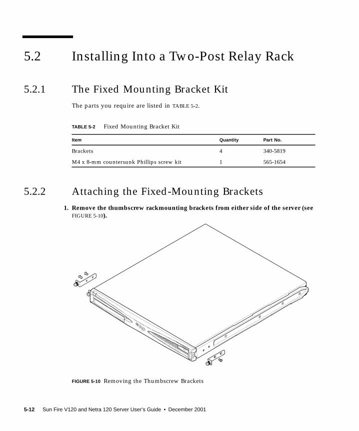
5.2 Installing Into a Two-Post Relay Rack 5-12
5.2.1 The Fixed Mounting Bracket Kit 5-12
5.2.2 Attaching the Fixed-Mounting Brackets 5-12
iv Sun Fire V120 and Netra 120 Server User’s Guide • December 2001

6. Connecting the Cables 6-1
6.1 Connecting the Cables to the Server 6-2
6.2 Using a Single DC Power Cord 6-4
6.3 Setting Up Serial Connections 6-4
6.3.1 Connecting to a Terminal Server 6-5
6.3.2 Using a DB-25 Adapter for Your Serial Link 6-7
6.3.3 Using a DB-9 Adapter for Your Serial Link 6-8
6.3.4 Settings for the Serial Connections 6-9
6.4 Connecting to Your Server From a Laptop Running Microsoft Windows
6-10
6.4.1 Connecting the Sun Fire V120 or Netra 120 Server to the Laptop
6-10
6.4.2 Using Microsoft Windows HyperTerminal 6-11
7. Powering On the Sun Fire V120 or Netra 120 Server 7-1
7.1 Preparing to Configure the Server 7-2
7.1.1 Using a Terminal Server 7-2
7.1.2 Configuring From a Terminal or Workstation 7-2
7.2 Powering On the Server 7-3
7.2.1 Powering On for the First Time With the Server’s Details Registered
at a Name Server 7-3
7.2.2 Powering On the Server for the First Time Without Having Its
Details Registered 7-4
7.2.3 Powering On a Standalone Server for the First Time 7-5
7.2.4 Clearing Your Configuration and Starting Again 7-6
7.3 Using the Power (On/Standby) Switch 7-7
Part II Remote and Local Management
8. Managing the Server From the lom> Prompt 8-1
8.1 Introduction to Lights-Out Management 8-2
8.2 Powering On or Resetting the Server From the LOM Shell 8-3
Contents v

8.2.1 Powering the Server On or Down to Standby Mode 8-4
8.2.2 Displaying the lom> Prompt 8-4
8.2.3 Exiting From the lom> Prompt 8-5
8.2.4 Resetting the Server 8-5
8.2.5 Displaying the ok or kadb Prompt 8-6
8.2.6 Controlling the Server’s Booting Behavior 8-6
8.3 Monitoring the Server From the LOM Shell 8-8
8.3.1 Checking How Long the Server Has Been Running 8-8
8.3.2 Checking the Current Status of All Components 8-8
8.3.3 Viewing the LOM Device’s Event Log 8-10
8.3.4 Checking That a Component Has Been Fixed 8-12
8.4 Setting Up LOM Privileges for Named Users 8-13
8.4.1 Permission Levels Available for LOM Users 8-13
8.4.2 Creating a LOM User Account 8-14
8.4.3 Specifying the Password for a LOM User Account 8-14
8.4.4 Viewing Details of a LOM User Account 8-15
8.4.5 Changing Your Own User Password 8-15
8.4.6 Deleting a LOM User Account 8-15
8.4.7 Specifying Permissions for a Named User 8-16
8.4.8 Quitting a LOM Named User Session 8-17
8.5 Setting the LOM Device’s Configurable Variables 8-17
8.5.1 Turning the Fault LED on 8-17
8.5.2 Turning the Fault LED off 8-17
8.5.3 Setting the alarmon n Software Flag 8-18
8.5.4 Setting the alarmoff n Software Flag 8-18
8.5.5 Stopping the LOM Sending Event Reports to the Serial A/LOM
port 8-18
8.6 Separating the LOM From the Console on the Serial A/LOM Port 8-19
8.6.1 Dedicating Serial A/LOM to the LOM 8-19
8.6.2 Sharing Serial A/LOM Between the LOM and the Console 8-20
vi Sun Fire V120 and Netra 120 Server User’s Guide • December 2001
8.7 Viewing the Event Reports That the LOM Sends to syslogd 8-20
8.8 The LOM Shell Command List 8-21
8.9 Checking the Status of the Server’s Fans 8-23
9. Managing the Server From the Solaris Prompt 9-1
9.1 Monitoring the System From Solaris 9-2
9.1.1 Viewing Online LOM Documentation 9-2
9.1.2 Checking the Power Supply Unit (lom -p ) 9-2
9.1.3 Checking the Fans (lom -f ) 9-3
9.1.4 Checking the Supply Rail Voltages and Internal Circuit Breakers
(lom -v ) 9-3
9.1.5 Checking the Internal Temperature (lom -t ) 9-4
9.1.6 Checking the Status of the Fault LED and Alarms (lom -l ) 9-5
9.1.7 Changing the LOM Automatic Server Restart Configuration (lom-w ) 9-5
9.1.8 Viewing the Configuration of the LOM Device (lom -c ) 9-6
9.1.9 Viewing All Component Status Data With the LOM Device’s
Configuration Data (lom -a ) 9-6
9.1.10 Viewing the Event Log (lom -e ) 9-7
9.2 Configuring Automatic Server Restart (ASR) 9-8
9.2.1 Configuring the LOM Watchdog to Restart the System After a
Lockup 9-8
9.2.2 Enabling the LOM Watchdog Process From Your Own Script or
Command (lom -W on ) 9-9
9.2.3 Setting the Hardware Reset Option From a Script or Command
(lom -R on ) 9-10
9.3 Other LOM Tasks You Can Perform From Solaris 9-11
9.3.1 Turning Alarms On and Off (lom -A ) 9-11
9.3.2 Turning the Fault LED On and Off (lom -F ) 9-11
9.3.3 Changing the First Character of the Sequence for Escaping to the
lom> Prompt (lom -X ) 9-12
9.3.4 Stopping the LOM from Sending Reports to the Serial A/LOM Port
(lom -E off ) 9-12
Contents vii

9.3.5 Making the LOM Interface Backward Compatible (lom -B ) 9-13
9.3.6 Upgrading the LOM Firmware
(lom -G filename) 9-13
Part III Troubleshooting and Maintenance
10. Troubleshooting 10-1
10.1 Introduction to the POST, obdiag , and SunVTS Diagnostic Tools 10-2
10.1.1 Using POST Diagnostics 10-2
10.1.2 Using OpenBoot Diagnostics (obdiag ) 10-3
10.1.3 Using SunVTS 10-5
10.2 Additional Diagnostic Tests for Specific Devices 10-8
10.2.1 Using the probe-scsi Command To Confirm That Hard Disk
Drives Are Active 10-8
10.2.2 Using the probe-ide Command To Confirm That the DVD or CD-
ROM Drive is Connected 10-9
10.2.3 Using the watch-net and watch-net-all Commands To Check
the Network Connections 10-9
10.3 Solutions to Problems You Might Encounter 10-10
10.4 Interpreting the Front and Back Panel LEDs 10-12
11. Replacing a Server or Replacing Individual Components 11-1
11.1 Replacing a Server 11-2
11.2 Field Replaceable Units 11-4
11.3 Replacing the Memory Card Reader for the System Configuration Card
11-5
11.4 Replacing the DVD or CD-ROM Drive, Cable, and Paddleboard 11-7
11.5 Replacing the NVRAM Chip 11-9
11.6 Replacing the System Board 11-12
11.6.1 Removing the Old System Board 11-12
11.6.2 Installing the New System Board 11-15
11.7 Replacing the Power Supply Unit 11-17
11.8 Replacing the Rear Fan Subassembly (Fans 1 and 2) 11-19
viii Sun Fire V120 and Netra 120 Server User’s Guide • December 2001
11.9 Replacing Fan 3 11-21
Part IV Appendixes
A. Installing and Removing a SCSI Hard Disk Drive with Solaris Running A-1
A.1 Installing a SCSI Hard Disk Drive With Solaris Running A-2
A.2 Removing a SCSI Hard Disk Drive With Solaris Running A-4
12. Reinstalling the Solaris Operating Environment B-1
B.1 Reinstalling Solaris B-2
B.2 Reinstalling the Lights-Out Management Software B-2
B. Configuring the LOM Device Driver C-1
C.1 The LOM Device Driver C-2
C.2 Configuring the LOM Device Driver C-3
C. System Board Jumper Settings D-1
Index 1
Contents ix

x Sun Fire V120 and Netra 120 Server User’s Guide • December 2001
Figures
FIGURE 1-1 The Sun Fire V120 Server 1-2
FIGURE 1-2 Contents of the Ship Kit 1-4
FIGURE 1-3 The Front Panel of the Sun Fire V120 and Netra 120 Servers 1-6
FIGURE 1-4 The Back Panel of the Sun Fire V120 Server 1-7
FIGURE 1-5 The Back Panel of the Netra 120 Server 1-7
FIGURE 3-1 The Location of the Grounding Studs for Connecting the Two-Hole Lug 3-2
FIGURE 3-2 Stripping the Insulation From the Wire 3-4
FIGURE 3-3 Opening the DC Connector Cage Clamp (Lever Method) 3-5
FIGURE 3-4 Opening the DC Connector Cage Clamp (Screwdriver Method) 3-6
FIGURE 3-5 Assembling the DC Input Power Cable 3-6
FIGURE 3-6 Inserting the Bottom Portion of the Strain Relief Housing 3-7
FIGURE 3-7 Routing the Wires Out of the Strain Relief Housing 3-8
FIGURE 3-8 Securing the Wires to the Strain Relief Housing 3-8
FIGURE 3-9 Assembling the Strain Relief Housing 3-9
FIGURE 4-1 Inserting and Removing Hard Disks 4-3
FIGURE 4-2 Using the Antistatic Wrist Strap Supplied With the Server 4-4
FIGURE 4-3 Removing the Top Cover 4-5
FIGURE 4-4 Components of the Sun Fire V120 and Netra 120 Servers 4-6
FIGURE 4-5 Installing an Internal DVD or CD-ROM Drive 4-8
xi

FIGURE 4-6 Installing Memory into a Socket on the System Board 4-10
FIGURE 4-7 The Rotating Retention Bracket and the Position of a PCI Card 4-12
FIGURE 4-8 Using the PCI Card Retainer, Slide Support Rail, and Plastic Bracket 4-13
FIGURE 4-9 Replacing the Top Cover 4-15
FIGURE 5-1 Cable Management Bracket 5-2
FIGURE 5-2 Positioning the Slide Mounts for a Sun StorEdge 72-Inch Tall Rack 5-3
FIGURE 5-3 Positioning the Slide Mounts for a Standard 19-Inch Wide Rack 5-3
FIGURE 5-4 Fastening the Slide Mounts to a Sun StorEdge 72-inch Tall Rack–Rear View (Side PanelsRemoved for Clarity) 5-5
FIGURE 5-5 Fastening the Slide Mounts to a Sun StorEdge 72-inch Expansion Rack–Front View (SidePanels Removed for Clarity) 5-6
FIGURE 5-6 Fastening the Slide Mounts to a Standard 19-inch Rack 5-7
FIGURE 5-7 Sliding the Server Into a Standard 19-Inch Rack 5-8
FIGURE 5-8 Adjusting the Slide Mounts and Screwing the Server Into the Rack 5-9
FIGURE 5-9 Fitting the Cable Management Bracket to a Sun StorEdge or a Standard 19-Inch Rack 5-10
FIGURE 5-10 Removing the Thumbscrew Brackets 5-12
FIGURE 5-11 Fitting the Fixed Mounting Brackets 5-13
FIGURE 5-12 The Server Installed in a Two-Post Rack 5-14
FIGURE 6-1 Connecting the Cables to the Sun Fire V120 Server 6-2
FIGURE 6-2 Connecting the Cables to the Netra 120 Server 6-2
FIGURE 6-3 Patch Panel Connection Between a Terminal Server and a Sun Fire V120 6-5
FIGURE 6-4 Pins 1 to 8 on the Serial Port 6-6
FIGURE 6-5 Pins 1 to 8 on the Serial Ports 6-7
FIGURE 6-6 Pins 1 to 8 on the Serial Ports 6-8
FIGURE 1 Connecting the Server to the Serial Port on a Laptop 6-10
FIGURE 7-1 Netra 120 Server Power (On/Standby) Switch 7-7
FIGURE 7-2 Sun Fire V120 Server Power (On/Standby) Switch 7-7
FIGURE 8-1 The Location of the Lights-Out Management Device on the System Board 8-2
FIGURE 8-2 Sample Output From the environment Command 8-9
xii Sun Fire V120 and Netra 120 Server User’s Guide • December 2001
FIGURE 8-3 Sample LOM Device Event Log (Oldest Event Reported First) 8-10
FIGURE 8-4 Locations of Fans 1, 2, 3, and 4 8-23
FIGURE 9-1 Sample LOM Device Event Log (Oldest Event Reported First) 9-7
FIGURE 10-1 Sample obdiag Menu 10-3
FIGURE 10-2 probe-scsi Output Message 10-8
FIGURE 10-3 probe-scsi-all Output Message 10-8
FIGURE 10-4 probe-ide Output Message 10-9
FIGURE 10-5 watch-net Diagnostic Output Message 10-10
FIGURE 10-6 watch-net-all Diagnostic Output Message 10-10
FIGURE 10-7 Front Panel Power and Fault LEDs 10-13
FIGURE 10-8 Back Panel Ethernet Link, Fault and Power LEDs 10-13
FIGURE 11-1 Replacing the System Configuration Card 11-3
FIGURE 11-2 Removing the System Configuration Card Reader 11-6
FIGURE 11-3 Replacing the Paddleboard at the Back of the DVD or CD-ROM Drive Enclosure 11-8
FIGURE 11-4 The Location of the NVRAM Chip 11-10
FIGURE 11-5 Replacing the NVRAM Chip 11-11
FIGURE 11-6 Unplugging and Removing the Fan 3 Assembly 11-13
FIGURE 11-7 The System Board 11-14
FIGURE 11-8 Replacing the Fan 3 Assembly 11-16
FIGURE 11-9 Replacing the Power Supply Unit 11-18
FIGURE 11-10 Replacing the Rear Fan Subassembly (Fans 1 and 2) 11-20
FIGURE 11-11 Disconnecting the Power Cable for Fan 3 and Lifting the Fan Out 11-21
FIGURE D-1 System Board Jumper Locations and Default Settings D-4
Figures xiii

xiv Sun Fire V120 and Netra 120 Server User’s Guide • December 2001
Tables
TABLE 1-1 Contents of the Ship Kit 1-3
TABLE 1-2 Customer-Installable Hardware and Software 1-5
TABLE 2-1 Operating Power Limits and Ranges for Sun Fire V120 and Netra 120 Servers 2-2
TABLE 2-2 Power Consumption for the Available Configurations of the Server 2-3
TABLE 5-1 19-inch Rackmounting Kit 5-2
TABLE 5-2 Fixed Mounting Bracket Kit 5-12
TABLE 6-1 Serial Port Connection to a Terminal Server 6-6
TABLE 6-2 Pin Inter-connections Performed by the Sun DB-25 (25-pin) Adapter 6-7
TABLE 6-3 Pin Inter-connections Required to be Performed by a DB-9 (9-pin) Adapter 6-8
TABLE 6-4 Default Settings for Connecting to the Serial A/LOM or Serial B Port 6-9
TABLE 6-5 Pin Inter-connections Required to be Performed by the 25x9-way D-type Female-to-FemaleAdapter 6-11
TABLE 8-1 Boot Modes 8-7
TABLE 8-2 LOM Commands 8-21
TABLE 10-1 Open Boot Diagnostics Tests 10-4
TABLE 10-2 SunVTS Tests 10-5
TABLE 11-1 FRUs Available for the Sun Fire V120 and Netra 120 Servers 11-4
TABLE C-1 LOM Configuration File Parameters C-3
TABLE D-1 Factory-Default Jumper Settings D-2
xv

xvi Sun Fire V120 and Netra 120 Server User’s Guide • December 2001

Preface
The Sun Fire V120 and Netra 120 Server User’s Guide describes how to install, manage,
and maintain the Sun FireTM V120 and NetraTM 120 servers. The manual is intended
for system administrators who have experience in setting up networked SolarisTM
servers.
How This Book Is Organized
Part I Installation and Configuration
Chapter 1 introduces the Sun FireTM V120 and NetraTM 120 servers, lists the
customer-installable hardware and software components available for them, and
identifies the main features of the servers’ front and back panels.
Chapter 2 provides information about the power and cooling requirements for the
Sun FireTM V120 and NetraTM 120 servers.
Chapter 3 describes how to assemble the DC input power cable.
Chapter 4 describes how to install optional (hot-pluggable) Hard Disk Drives and
also how to open the server, identify its components, and install memory DIMMs, a
PCI expansion card, or a DVD or CD-ROM drive.
Chapter 5 describes how to install the server into different types of racks.
Chapter 6 describes how to connect the cables and set up serial connections to the
server.
Chapter 7 describes how to perform the initial power-on and configuration of the
server.
xvii
Part II Remote and Local Management
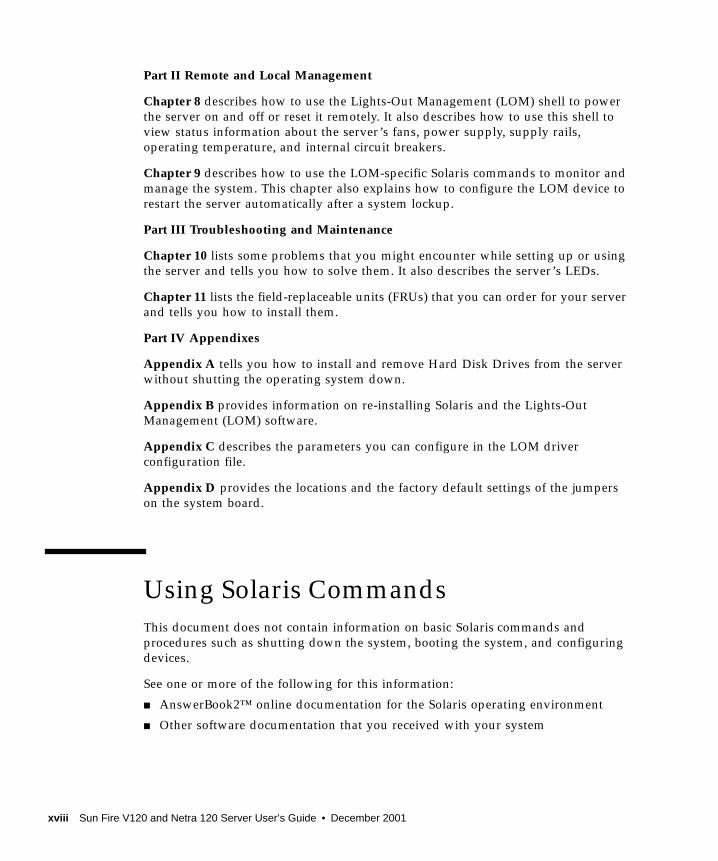
Chapter 8 describes how to use the Lights-Out Management (LOM) shell to power
the server on and off or reset it remotely. It also describes how to use this shell to
view status information about the server’s fans, power supply, supply rails,
operating temperature, and internal circuit breakers.
Chapter 9 describes how to use the LOM-specific Solaris commands to monitor and
manage the system. This chapter also explains how to configure the LOM device to
restart the server automatically after a system lockup.
Part III Troubleshooting and Maintenance
Chapter 10 lists some problems that you might encounter while setting up or using
the server and tells you how to solve them. It also describes the server’s LEDs.
Chapter 11 lists the field-replaceable units (FRUs) that you can order for your server
and tells you how to install them.
Part IV Appendixes
Appendix A tells you how to install and remove Hard Disk Drives from the server
without shutting the operating system down.
Appendix B provides information on re-installing Solaris and the Lights-Out
Management (LOM) software.
Appendix C describes the parameters you can configure in the LOM driver
configuration file.
Appendix D provides the locations and the factory default settings of the jumpers
on the system board.
Using Solaris Commands
This document does not contain information on basic Solaris commands and
procedures such as shutting down the system, booting the system, and configuring
devices.
See one or more of the following for this information:
■ AnswerBook2™ online documentation for the Solaris operating environment
■ Other software documentation that you received with your system
xviii Sun Fire V120 and Netra 120 Server User’s Guide • December 2001

Typographic Conventions
Shell Prompts
Typeface Meaning Examples
AaBbCc123 The names of commands, files,
and directories; on-screen
computer output
Edit your .login file.
Use ls -a to list all files.
% You have mail .
AaBbCc123 What you type, when
contrasted with on-screen
computer output
% suPassword:
AaBbCc123 Book titles, new words or
terms, words to be emphasized
Command-line variable;
replace with a real name or
value
Read Chapter 6 in the User’s Guide.
These are called class options.
You must be superuser to do this.
To delete a file, type rm filename.
Shell Prompt
C shell machine_name%
C shell superuser machine_name#
Bourne shell and Korn shell $
Bourne shell and Korn shell superuser #
LOM shell lom>
Preface xix

Related Documentation
Accessing Sun Documentation Online
A selection of Sun sytem documentation is located at:
■ http://www.sun.com/products-n-solutions/hardware/docs
A complete set of Solaris documentation and many other titles are located at:
■ http://docs.sun.com
Sun Welcomes Your Comments
Sun is interested in improving its documentation and welcomes your comments and
suggestions. You can email your comments to Sun at:
Please include the part number (816-2090-10) of your document in the subject line of
your email.
Application Title Part Number
Installation Sun Fire V120 and Netra 120 Servers:Product Notes
816-2093-xx
Installation overview Sun Fire V120 and Netra 120 Servers:Setup Poster
816-2091-xx
Safety Sun Fire V120, Netra 120, and Netra T1Servers: Safety and Compliance Guide
806-6135-xx
xx Sun Fire V120 and Netra 120 Server User’s Guide • December 2001

Safety Precautions
For your protection, observe the following safety precautions when setting up your
equipment:
■ Follow all cautions and instructions marked on the equipment.
■ Never push objects of any kind through openings in the equipment. Dangerous
voltages may be present. Conductive foreign objects can produce a short circuit
that could cause fire, electric shock, or damage to your equipment.
Symbols
The following symbols may appear in this manual:
Caution – There is a risk of personal injury and equipment damage. Follow the
instructions.
Caution – Hazardous voltages are present. To reduce the risk of electric shock and
danger to personal health, follow the instructions.
Preface xxi

xxii Sun Fire V120 and Netra 120 Server User’s Guide • December 2001

PART I Installation and Configuration

CHAPTER 1
Introduction
This chapter lists the features of the Sun Fire V120 and Netra 120 servers, the
contents of the ship kit, and the optional hardware and software that is available for
them. It also describes the front and back panels, lists the tools you will need to use
to install a server, and describes the servers’ tolerance of, or suitability for, various
environmental conditions. Finally, the chapter offers some guidance to help you
decide whether to mount the system in a rack or a cabinet.
The chapter contains the following sections:
■ Section 1.1, “Overview of the Sun Fire V120 and Netra 120 Servers” on page 1-2
■ Section 1.2, “Contents of the Ship Kit” on page 1-3
■ Section 1.3, “Optional Hardware and Software” on page 1-5
■ Section 1.4, “Front Panel” on page 1-6
■ Section 1.5, “Back Panel” on page 1-7
■ Section 1.6, “The Fans Inside the Sun Fire V120 and Netra 120 Servers” on
page 1-8
■ Section 1.8, “Environmental Specifications” on page 1-9
■ Section 1.9, “Choosing Between a Rack and a Cabinet” on page 1-10
1-1

1.1 Overview of the Sun Fire V120 and Netra120 Servers
FIGURE 1-1 The Sun Fire V120 Server
The Sun FireTM V120 and NetraTM 120 servers are single-processor, thin (1U) servers
designed primarily for use by telecommunications carriers and internet service
providers. They are also suitable for use within corporate customer networks,
wherever there is a need to maximize the density of high-performance Solaris
servers.
The Sun Fire V120 and Netra 120 servers are identical except that the Sun Fire V120
is powered by an AC supply and the Netra 120 by –48VDC/–60VDC supplies. This
is the only difference between the two models.
The servers both have the following features:
■ Rackmounting enclosure with single power supply
■ UltraSPARCTM IIe+ 550 or 650 MHz processor
■ Four DIMM sockets accepting 256 MB or 512 MB PC133 memory modules (giving
a maximum of 2 GB of memory)
■ One 33-MHz, 32-bit, 5V PCI card slot
■ Two 10/100 Mbps RJ-45 Ethernet ports
■ Console/Lights-Out Management (LOM) RJ-45 serial port
1-2 Sun Fire V120 and Netra 120 Server User’s Guide • December 2001
■ Second RJ-45 serial port
■ Optional DVD or CD-ROM drive
■ Support for up to two low-profile, 3.5-inch Fast-40 (Ultra2SCSI) disks
■ Support for up to two USB connections
■ External Fast-40 (Ultra2SCSI) Multimode 68-pin port
These servers are designed to be rackmounted. Their components are housed in a
casing with the following dimensions:
■ Height: 1.72 inches (43.6 mm)
■ Width: 17.2 inches (436.7 mm)
■ Depth: 18.8 inches (478 mm)
■ Weight (when all option modules are installed): 10 kg (22 lb)
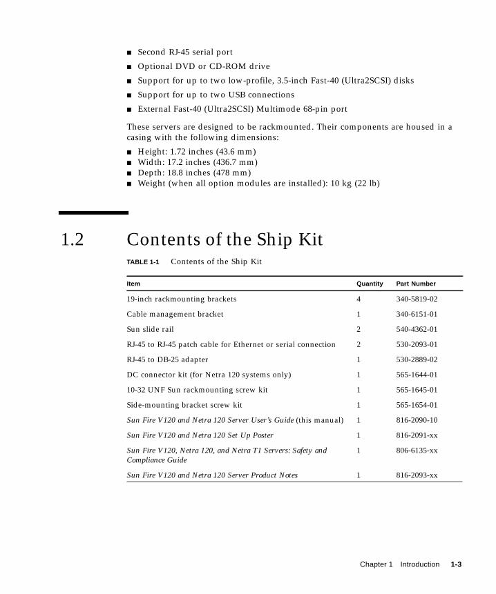
1.2 Contents of the Ship KitTABLE 1-1 Contents of the Ship Kit
Item Quantity Part Number
19-inch rackmounting brackets 4 340-5819-02
Cable management bracket 1 340-6151-01
Sun slide rail 2 540-4362-01
RJ-45 to RJ-45 patch cable for Ethernet or serial connection 2 530-2093-01
RJ-45 to DB-25 adapter 1 530-2889-02
DC connector kit (for Netra 120 systems only) 1 565-1644-01
10-32 UNF Sun rackmounting screw kit 1 565-1645-01
Side-mounting bracket screw kit 1 565-1654-01
Sun Fire V120 and Netra 120 Server User’s Guide (this manual) 1 816-2090-10
Sun Fire V120 and Netra 120 Set Up Poster 1 816-2091-xx
Sun Fire V120, Netra 120, and Netra T1 Servers: Safety andCompliance Guide
1 806-6135-xx
Sun Fire V120 and Netra 120 Server Product Notes 1 816-2093-xx
Chapter 1 Introduction 1-3
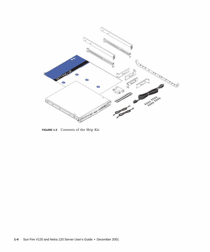
FIGURE 1-2 Contents of the Ship Kit
1-4 Sun Fire V120 and Netra 120 Server User’s Guide • December 2001
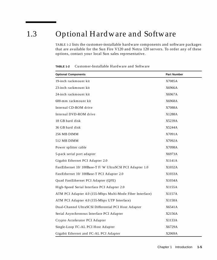
1.3 Optional Hardware and SoftwareTABLE 1-2 lists the customer-installable hardware components and software packages
that are available for the Sun Fire V120 and Netra 120 servers. To order any of these
options, contact your local Sun sales representative.
TABLE 1-2 Customer-Installable Hardware and Software
Optional Components Part Number
19-inch rackmount kit X7085A
23-inch rackmount kit X6966A
24-inch rackmount kit X6967A
600-mm rackmount kit X6968A
Internal CD-ROM drive X7088A
Internal DVD-ROM drive X1288A
18 GB hard disk X5239A
36 GB hard disk X5244A
256 MB DIMM X7091A
512 MB DIMM X7092A
Power splitter cable X7098A
5-pack serial port adapter X6973A
Gigabit Ethernet PCI Adapter 2.0 X1141A
FastEthernet 10/100Base-T F/W UltraSCSI PCI Adapter 1.0 X1032A
FastEthernet 10/100Base-T PCI Adapter 2.0 X1033A
Quad FastEthernet PCI Adapter (QFE) X1034A
High-Speed Serial Interface PCI Adapter 2.0 X1155A
ATM PCI Adapter 4.0 (155-Mbps Multi-Mode Fiber Interface) X1157A
ATM PCI Adapter 4.0 (155-Mbps UTP Interface) X1158A
Dual-Channel UltraSCSI Differential PCI Host Adapter X6541A
Serial Asynchronous Interface PCI Adapter X2156A
Crypto Accelerator PCI Adapter X1133A
Single-Loop FC-AL PCI Host Adapter X6729A
Gigabit Ethernet and FC-AL PCI Adapter X2069A
Chapter 1 Introduction 1-5

1.4 Front PanelThe illustration below shows the location of the Power and Fault LEDs, and the
DVD-ROM drive bay.
FIGURE 1-3 The Front Panel of the Sun Fire V120 and Netra 120 Servers
Power LED
DVD-ROM drive bay
Fault LED
1-6 Sun Fire V120 and Netra 120 Server User’s Guide • December 2001
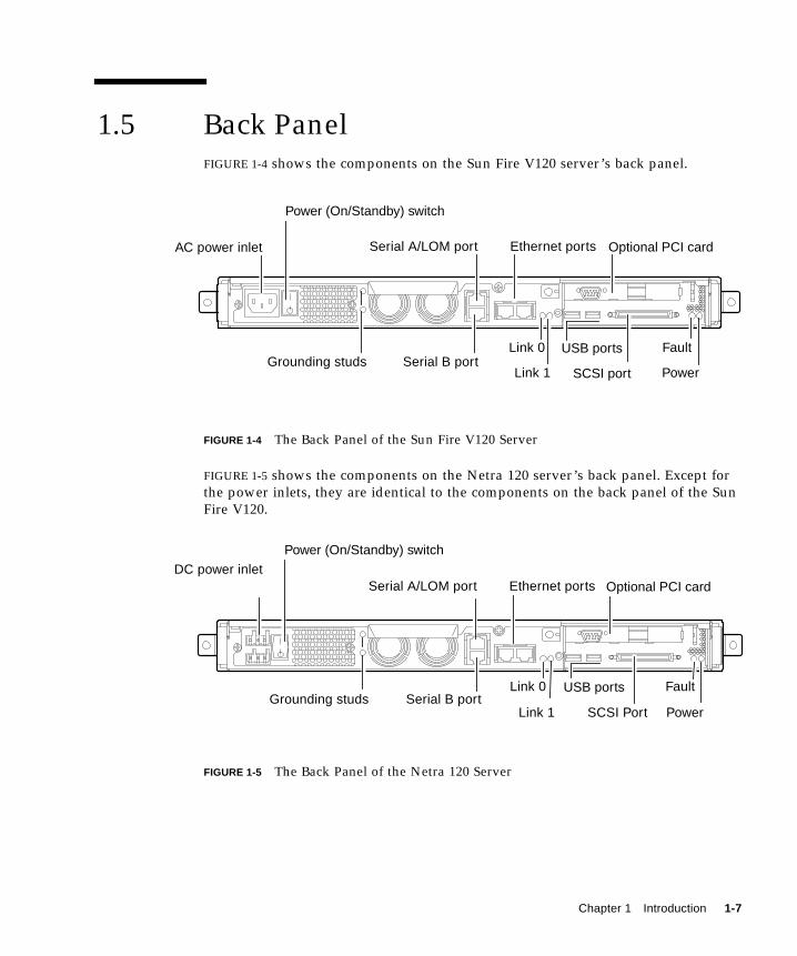
1.5 Back PanelFIGURE 1-4 shows the components on the Sun Fire V120 server’s back panel.
FIGURE 1-4 The Back Panel of the Sun Fire V120 Server
FIGURE 1-5 shows the components on the Netra 120 server’s back panel. Except for
the power inlets, they are identical to the components on the back panel of the Sun
Fire V120.
FIGURE 1-5 The Back Panel of the Netra 120 Server
Power (On/Standby) switch
Optional PCI card
USB ports
SCSI port
Link 0
Link 1
Fault
PowerGrounding studs Serial B port
Serial A/LOM port Ethernet ports
Power (On/Standby) switch
Optional PCI card
USB portsLink 0
Link 1
Fault
PowerGrounding studs Serial B port
Serial A/LOM port Ethernet ports
SCSI Port
DC power inlet
AC power inlet
Chapter 1 Introduction 1-7
1.6 The Fans Inside the Sun Fire V120 andNetra 120 ServersThe Sun Fire V120 and Netra 120 servers contain four fans. These are monitored by
the LOM device, so you can use the Lights-Out Management (LOM) commands to
check their status. For more information, see Chapter 8 and Chapter 9.
For a diagram showing the position of the fans inside the server, see “Identifying
Server Components” on page 4-6.
1.7 Tools You Need for Installation■ An 8-mm wrench (for assembling the rackmounting).
■ A small flat-head screwdriver (for levering the grilles when installing hard disks).
■ An ESD pad and an antistatic wrist strap and earthing point (to protect the
components of the system if you need to install any hardware options).
■ A No. 2 Phillips screwdriver.
■ For Netra 120 servers that are stacked on top of each other in a rack, you need to
use a right-angled two-hole lug. Use a UL/CSA-approved component, such as the
one supplied by Thomas & Betts (part number: 54204-UB). You will also need a
crimping tool, such as the Thomas & Betts crimping tool (part number: TBM 5-S).
1-8 Sun Fire V120 and Netra 120 Server User’s Guide • December 2001

1.8 Environmental SpecificationsThis section gives storage, operating and environmental compliance information.
1.8.1 Tolerance of Environmental Conditions
You can operate and store the system safely in the following conditions:
■ Ambient temperature
■ Operating: 5˚C to 40˚C (temporary operation outside these limits is permitted
for a maximum of 96 hours within the range –5˚C to 55˚C)
■ Storage: –40˚C to 70˚C
■ Relative humidity
■ Operating: 5% to 85% (non-condensing)
■ Storage: 10% to 95% (non-condensing)
■ Altitude
■ Operating: –300m to +3000m
■ Storage: –300m to +12000m
■ Earthquake
The system conforms to the NEBS requirements for earthquake zone 4
1.8.2 Acoustic Noise Generated by the Server
The server generates less than 60dBA at a distance of 23.67 inches (600mm) and a
height of 59.17 inches (1500mm) while operating in an ambient temperature of 25˚C.
1.8.3 Environmental Compliance Information■ NEBS environmental criteria
The system conforms to GR-63-CORE issue 1, October 1995
■ Electromagnetic compatibility
■ Immunity: The system conforms to GR-1089-CORE and EN50082-1
■ Emissions: The system conforms to GR-1089-CORE, EN55022 Class A and FCC
Class A
■ Safety
The system conforms to UL 1950 (3rd edition), EN60950, GR-1089-CORE
Chapter 1 Introduction 1-9

1.9 Choosing Between a Rack and a CabinetYou can install the Sun Fire V120 or Netra 120 server in either a rack or a cabinet.
Factors that might influence your decision include:
■ SecurityIf other people have access to the room in which your server is located, you can
increase security by locking the server in a cabinet.
■ Thermal issuesCabinets often require additional fans, because the servers you install in them are
generating heat in an enclosed space. Two-post racks, however, might require no
special cooling systems.
■ FlooringTwo-post telco relay racks are designed so that cables can be run overhead.
Cabinets often require cables to be run under the floor.
What’s Next?
When you have read this chapter, go to Chapter 2 to find out how to estimate the
power and cooling requirements for your server.
1-10 Sun Fire V120 and Netra 120 Server User’s Guide • December 2001
CHAPTER 2
Power and Cooling
This chapter contains information about the power consumption of the Sun Fire
V120 and Netra 120 servers. It also tells you how to estimate the amount of heat that
your cooling system must dissipate.
The chapter contains the following sections:
■ Section 2.1, “Operating Power Limits and Ranges” on page 2-2
■ Section 2.2, “Power Consumption” on page 2-3
■ Section 2.3, “Estimating Heat Dissipation” on page 2-4
Note – The power supply on the Sun Fire V120 server continues to regulate all
outputs for at least 20 milliseconds after AC power is removed. On the Netra 120
server, the power supply continues to regulate all outputs for at least 4.5
milliseconds after DC power is removed.
Note – Standby power is available whenever input power is connected.
2-1

2.1 Operating Power Limits and RangesThe table below gives operating and power information for the Sun Fire V120 and
Netra 120 servers.
*For both servers, the in-rush current decays to the normal operating current in less than
200 milliseconds. The in-rush decaying peaks last for less than 3 milliseconds in each half
cycle.
Note – The figures for the maximum operating current are provided to help you
specify the fusing and cabling you need to deliver power to your equipment.
However, these figures represent “worst-case” scenarios. Such occurrences are
unlikely in a real installation.
TABLE 2-1 Operating Power Limits and Ranges for Sun Fire V120 and Netra 120 Servers
Description Sun Fire V120 Server (AC power) Netra 120 Server (DC power)
Maximum operating
current
2A @ 90 VAC 4A @ –40 VDC
Maximum in-rush
current (cold start)
20A peak upon a restart
performed 60 seconds or more
after the removal of AC power
20A peak upon a restart
performed 60 seconds or more
after the removal of DC power
Maximum in-rush
current (warm start)
40A peak upon a restart
performed less than 60 seconds
but more than 200 milliseconds
after the removal of AC power
40A peak upon a restart
performed less than 60 seconds
but more than 200 milliseconds
after the removal of DC power
Maximum in-rush
current (hot start)
100A peak upon a restart
performed less than 200
milliseconds after the removal
of AC power
100A peak upon a restart
performed less than 200
milliseconds after the removal
of DC power
Operating input
voltage range
90-264 Vrms –40 to –75 VDC
Voltage frequency
range
47-63 Hz DC
Power factor 0.8 to 1.0 Not applicable
BTU rating 550 BTU 550 BTU
2-2 Sun Fire V120 and Netra 120 Server User’s Guide • December 2001

2.2 Power ConsumptionTo estimate the total power consumption for several Sun Fire V120 or Netra 120
servers installed in a single rack or cabinet, add together the individual power
requirement figures for each of the systems that you have installed (see TABLE 2-2).
Note – Adding optional hardware components to your system will increase its
power consumption. For a list of the optional hardware components available for
these servers, see Section 1.3, “Optional Hardware and Software” on page 1-5.
TABLE 2-2 Power Consumption for the Available Configurations of the Server
Server Model Hardware OptionsInstalled
Power Consumption(Nominal)
Power Consumption(Maximum)
Sun Fire V120 550MHz CPU
36 GB hard disk
512 MB DIMM
55 W 73 VA
Sun Fire V120 650MHz CPU
2x36 GB hard disk
1 GB DIMM
74 W 100 VA
Sun Fire V120 650MHz CPU
1x36 GB hard disk
512 MB DIMM
58 W 78 VA
Netra 120 650MHz CPU
36 GB hard disk
512 MB DIMM
58 W 70 W
Chapter 2 Power and Cooling 2-3
2.3 Estimating Heat DissipationTo estimate the amount of heat generated by a Sun Fire V120 or Netra 120 server so
that you can estimate the heat your cooling system must dissipate (see Section 2.2,
“Power Consumption” on page 2-3), convert the figure for the server’s power
consumption from watts to BTU per hour.
A general formula for doing this is to multiply the figure for the power consumption
by 3.415. For example, the heat that must be dissipated for a Sun Fire V120 server
containing a 650 MHz processor, a single 36 GB hard disk drive, and a single 512 MB
DIMM is:
58 x 3.415 = 198.07 BTU/hr
You can install up to 32 Sun Fire V120 or Netra 120 servers into a Sun StorEdge 72-
inch rack. To estimate the heat your cooling system must dissipate, add together the
nominal power consumption for each server in the rack, then multiply the result by
3.415. For example, 30 servers each containing a 650 MHz processor, containing a
single 36 GB hard disk and a single 512 MB DIMM will generate the following
amount of heat:
(30 x 58 W) x 3.415 = 5942.10 BTU/hr
What’s Next?
When you have used this chapter to estimate the power and cooling requirements
for your server, go to Chapter 3, which tells you how to assemble the DC input
power cables for the Netra 120 server; or if you are installing a Sun Fire V120 server,
go straight to Chapter 4 to find out how to install the optional hardware components
available for both servers.
2-4 Sun Fire V120 and Netra 120 Server User’s Guide • December 2001
CHAPTER 3
Using DC Power
This chapter applies only to the Netra 120 server. If you have purchased a
Sun Fire V120 server, skip this chapter and go to Chapter 4.
This chapter provides information on grounding a Netra 120 server and on
assembling the DC power connectors.
It contains the following sections:
■ Section 3.1, “Grounding the Netra 120 Server” on page 3-2
■ Section 3.2, “Assembling the DC Power Connectors” on page 3-3
3-1

3.1 Grounding the Netra 120 ServerThe two M5 grounding studs on the server’s back panel are the recommended safety
grounding point (see FIGURE 3-1). However, an alternative grounding point is
provided by the middle pin of the WAGO connector.
FIGURE 3-1 The Location of the Grounding Studs for Connecting the Two-Hole Lug
● To ground the server, take a ground conductor and terminate it using a right-angled two-hole lug.
Make sure that it is UL/CSA-approved, that it is suitable for an 8 AWG (6mm2)
conductor, and that it has a 5/8-inch pitch.
Note – For Netra 120 servers that are stacked on top of each other in a rack, you
need to use a right-angled two-hole lug. Use a UL/CSA-approved component, such
as the one supplied by Thomas & Betts (part number: 54204-UB).
● To secure the lug onto the ground conductor cable, use a UL/CSA-approvedcrimping tool, such as the one supplied by Thomas & Betts (part number: TBM 5-S).
Do not use a torque value of more than 3.5 Nm maximum.
Connect the free end of the ground conductor cable to an earthing bar located near
to the equipment.
Caution – External filtering and/or surge suppression devices may be required on
the power feeds where branch circuit electromagnetic characteristics are unknown.
Note – For more information about grounding the server, refer to the Sun Fire V120,Netra 120, and Netra T1 Servers: Safety and Compliance Guide (part number: 816-3211).
M5 groundingstuds
3-2 Sun Fire V120 and Netra 120 Server User’s Guide • December 2001
3.2 Assembling the DC Power ConnectorsThe Netra 120 server has a dedicated connector kit; this section explains how to use
it.
3.2.1 The Insulated Conductors You Need to Use
The insulated conductors you use must have the following characteristics:
■ Material: tinned copper (multistranded)
■ Size: 12 AWG (2.5 mm2) (maximum)
■ Rating:
■ 300 vrms (minimum)
■ 75O C
■ Low-smoke fume (LSF)
■ Fire resistance:
■ VW-1
■ GR63-CORE compliant
You need two supply conductors:
■ One -48V (or -60V) DC supply conductor (return, RTN) grounded at source
■ One DC supply conductor (- minus)
Finally, you need one power supply unit (PSU) ground conductor.
3.2.2 Assembling the DC Input Power Cable
1. Determine how many DC input power cables you will need from each DC powersource.
2. Turn off power to the DC power source through the circuit breakers.
Caution – Do not proceed with these instructions until you have turned off the
power to the DC power source through the circuit breakers.
3. Take a DC connector from the ship kit.
4. Locate the Supply and Return wires (and the PSU Ground, if you are using it)coming from the DC power source that you intend to use in the connection to yourserver:
Chapter 3 Using DC Power 3-3
■ –48V Supply
■ PSU Ground
■ –48V Return
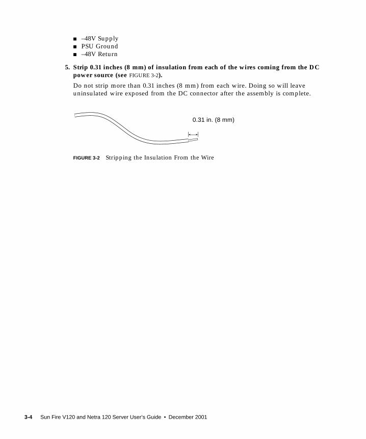
5. Strip 0.31 inches (8 mm) of insulation from each of the wires coming from the DCpower source (see FIGURE 3-2).
Do not strip more than 0.31 inches (8 mm) from each wire. Doing so will leave
uninsulated wire exposed from the DC connector after the assembly is complete.
FIGURE 3-2 Stripping the Insulation From the Wire
0.31 in. (8 mm)
3-4 Sun Fire V120 and Netra 120 Server User’s Guide • December 2001
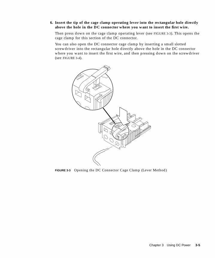
6. Insert the tip of the cage clamp operating lever into the rectangular hole directlyabove the hole in the DC connector where you want to insert the first wire.
Then press down on the cage clamp operating lever (see FIGURE 3-3). This opens the
cage clamp for this section of the DC connector.
You can also open the DC connector cage clamp by inserting a small slotted
screwdriver into the rectangular hole directly above the hole in the DC connector
where you want to insert the first wire, and then pressing down on the screwdriver
(see FIGURE 3-4).
FIGURE 3-3 Opening the DC Connector Cage Clamp (Lever Method)
Chapter 3 Using DC Power 3-5

FIGURE 3-4 Opening the DC Connector Cage Clamp (Screwdriver Method)
7. Feed the exposed section of the appropriate wire into that hole in the DCconnector.
FIGURE 3-5 shows which wires should be inserted into each hole in the DC connector.
FIGURE 3-5 Assembling the DC Input Power Cable
8. Repeat Step 6 and Step 7 for the other two wires to complete the assembly of theDC input power cable.
9. Repeat Step 4 through Step 8 to create a second DC input power cable.
If you need to remove a wire from the DC connector, insert the cage clamp operating
lever or a small screwdriver into the slot directly above the wire and press down
(FIGURE 3-3 and FIGURE 3-4).
Top of connector
Top of connector
–48V Return
Ground
–48V
12
3
3-6 Sun Fire V120 and Netra 120 Server User’s Guide • December 2001

3.2.3 Installing the Strain Relief Housings
1. Insert the bottom portion of the strain relief housing into the notch on the DCconnector until it snaps into place (see FIGURE 3-6).
Make sure that the strain relief housing snaps into place on the DC connector,
otherwise you will not be able to complete the assembly correctly.
FIGURE 3-6 Inserting the Bottom Portion of the Strain Relief Housing
2. Route the three wires coming from the DC power source through the opening atthe end of the bottom portion of the strain relief housing (see FIGURE 3-7).
Chapter 3 Using DC Power 3-7
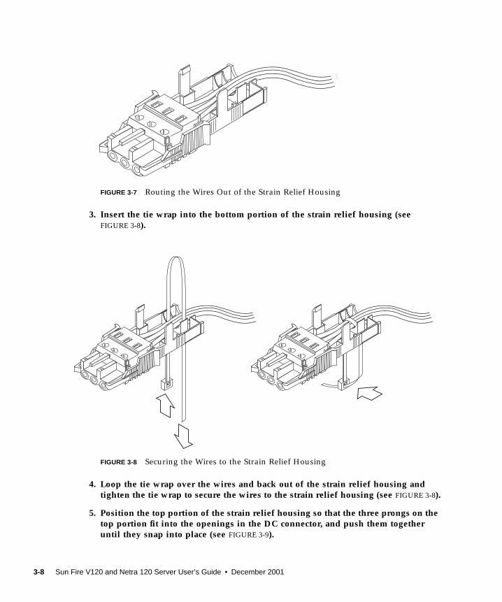
FIGURE 3-7 Routing the Wires Out of the Strain Relief Housing
3. Insert the tie wrap into the bottom portion of the strain relief housing (seeFIGURE 3-8).
FIGURE 3-8 Securing the Wires to the Strain Relief Housing
4. Loop the tie wrap over the wires and back out of the strain relief housing andtighten the tie wrap to secure the wires to the strain relief housing (see FIGURE 3-8).
5. Position the top portion of the strain relief housing so that the three prongs on thetop portion fit into the openings in the DC connector, and push them togetheruntil they snap into place (see FIGURE 3-9).
3-8 Sun Fire V120 and Netra 120 Server User’s Guide • December 2001
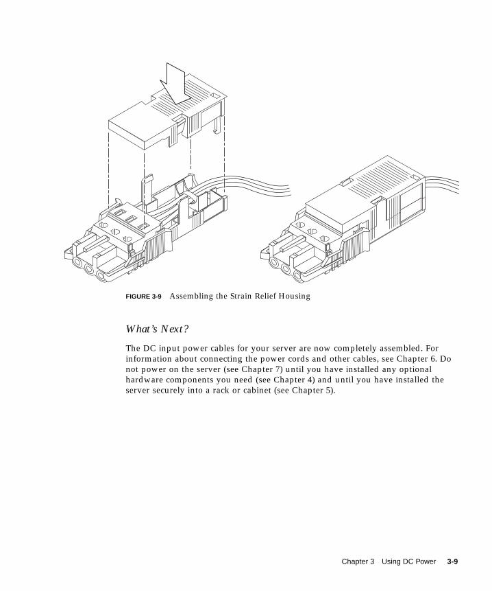
FIGURE 3-9 Assembling the Strain Relief Housing
What’s Next?
The DC input power cables for your server are now completely assembled. For
information about connecting the power cords and other cables, see Chapter 6. Do
not power on the server (see Chapter 7) until you have installed any optional
hardware components you need (see Chapter 4) and until you have installed the
server securely into a rack or cabinet (see Chapter 5).
Chapter 3 Using DC Power 3-9

3-10 Sun Fire V120 and Netra 120 Server User’s Guide • December 2001
CHAPTER 4
Installing Optional HardwareComponents
If you do not want to install any optional hardware components, skip this chapter
and go straight to Chapter 5, which tells you how to install the Sun Fire V120 and
Netra 120 servers into a rack.
This chapter tells you how to install or remove the hot-pluggable Hard Disk Drives.
To do this, you do not need to power off the server or remove it from the rack. This
chapter also tells you how to remove the cover of the server, how to identify the
parts of the server, how to install a DVD or CD-ROM drive, and how to install
DIMMs and a PCI card.
For the part numbers of the hardware components available from your local Sun
sales representative, see Section 1.3, “Optional Hardware and Software” on page 1-5.
This chapter contains the following sections:
■ Section 4.1, “Installing and Removing Hot-Pluggable SCSI Hard Disk Drives” on
page 4-2
■ Section 4.2, “Opening the Server” on page 4-4
■ Section 4.3, “Identifying Server Components” on page 4-6
■ Section 4.4, “Installing and Removing a DVD or CD-ROM Drive” on page 4-7
■ Section 4.5, “Installing and Removing Memory” on page 4-9
■ Section 4.6, “Installing and Removing a PCI Card” on page 4-11
■ Section 4.7, “Replacing the Server’s Top Cover” on page 4-14
4-1
4.1 Installing and Removing Hot-PluggableSCSI Hard Disk Drives
Note – The server and Hard Disk Drives contain electronic parts that are extremely
sensitive to static electricity. Do not touch any metal parts. Wear an antistatic wrist
strap.
The Hard Disk Drives are hot-pluggable modules. This means that you do not need
to power off the server or remove it from the rack to install or remove the Hard Disk
Drives.
However, you do need to make sure that no system or application software is using
a Hard Disk Drive when you remove it.
Note – If you intend to remove a Hard Disk Drive with Solaris running, follow the
instructions in Appendix A before performing the steps below.
1. Remove the front bezel.
Release the bezel from the server by pressing in on the tabs at either end of the bezel.
2. Pull out the grilles.
3. Do one of the following:
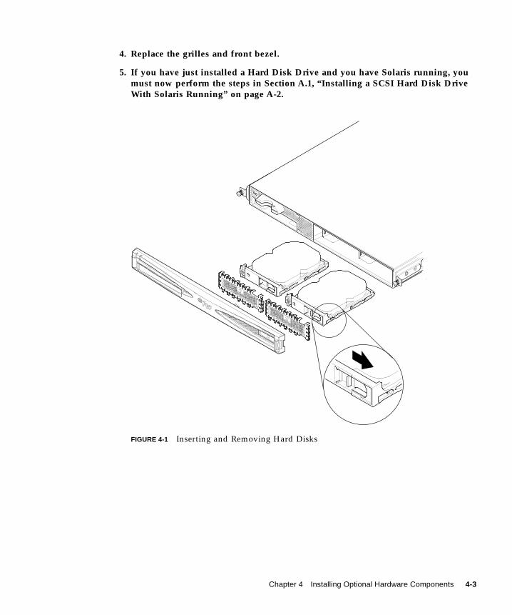
■ If you are installing a Hard Disk Drive, slide it into its tray at the front of the
server (see FIGURE 4-1). Push it in firmly until the metal lever starts to close: this
indicates that it has engaged with the backplane connector. Then, push the metal
lever until the disk drive clicks into place.
Note – When inserting a Hard Disk Drive into its enclosure, make sure the top of
the drive is touching the top of the enclosure. If you try to install it with the bottom
of the drive touching the bottom of the enclosure, the drive will not align with the
slide rails inside the enclosure, and you will not be able to insert the disk.
■ If you are removing a Hard Disk Drive, locate the latch at the front of the disk and
slide it to the right (see FIGURE 4-1). This causes the metal lever to open. Holding
the latch, pull the disk part way out of its bay and leave it for a minute to make
sure it has stopped spinning. (If a disk is fully removed while it is still spinning,
gyroscopic forces can damage its bearings.) When it has stopped spinning, pull it
out of the chassis.
4-2 Sun Fire V120 and Netra 120 Server User’s Guide • December 2001
4. Replace the grilles and front bezel.
5. If you have just installed a Hard Disk Drive and you have Solaris running, youmust now perform the steps in Section A.1, “Installing a SCSI Hard Disk DriveWith Solaris Running” on page A-2.
FIGURE 4-1 Inserting and Removing Hard Disks
Chapter 4 Installing Optional Hardware Components 4-3

4.2 Opening the Server
Caution – The server contains electronic parts that are extremely sensitive to static
electricity. Do not touch any metal parts. Place the server on top of a grounded
electrostatic discharge (ESD) pad. Attach the disposable antistatic wrist strap
supplied with the server to its metal base before touching any of the internal
components.
Caution – Before attempting to remove the cover, make sure that all power cords
and all other cables have been disconnected from the server.
FIGURE 4-2 Using the Antistatic Wrist Strap Supplied With the Server
ESD pad
4-4 Sun Fire V120 and Netra 120 Server User’s Guide • December 2001
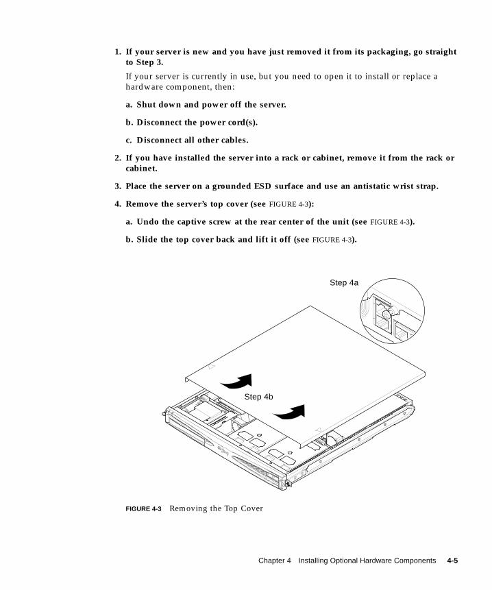
1. If your server is new and you have just removed it from its packaging, go straightto Step 3.
If your server is currently in use, but you need to open it to install or replace a
hardware component, then:
a. Shut down and power off the server.
b. Disconnect the power cord(s).
c. Disconnect all other cables.
2. If you have installed the server into a rack or cabinet, remove it from the rack orcabinet.
3. Place the server on a grounded ESD surface and use an antistatic wrist strap.
4. Remove the server’s top cover (see FIGURE 4-3):
a. Undo the captive screw at the rear center of the unit (see FIGURE 4-3).
b. Slide the top cover back and lift it off (see FIGURE 4-3).
FIGURE 4-3 Removing the Top Cover
Step 4b
Step 4a
Chapter 4 Installing Optional Hardware Components 4-5
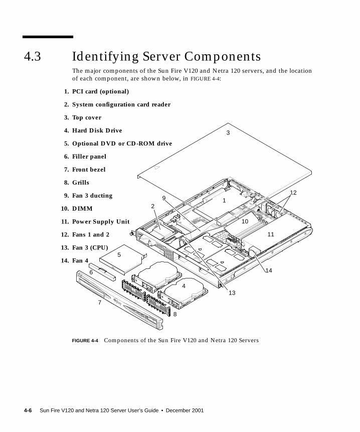
4.3 Identifying Server Components
FIGURE 4-4 Components of the Sun Fire V120 and Netra 120 Servers
The major components of the Sun Fire V120 and Netra 120 servers, and the location
of each component, are shown below, in FIGURE 4-4:
1. PCI card (optional)
2. System configuration card reader
3. Top cover
4. Hard Disk Drive
5. Optional DVD or CD-ROM drive
6. Filler panel
7. Front bezel
8. Grills
9. Fan 3 ducting
10. DIMM
11. Power Supply Unit
12. Fans 1 and 2
13. Fan 3 (CPU)
14. Fan 4
12
3
4
5
6
8
9
10
11
12
14
13
7
4-6 Sun Fire V120 and Netra 120 Server User’s Guide • December 2001
4.4 Installing and Removing a DVD orCD-ROM Drive
Caution – Follow the instructions in this section carefully. The DVD or CD-ROM
drive contains a laser device. Do not attempt to open the DVD or CD-ROM drive’s
enclosure or remove a DVD or CD-ROM drive using any procedures other than
those contained in this section. If you do, you risk exposure to radiation.
4.4.1 Installing a DVD or CD-ROM Drive
Note – If you are going to install a full-length PCI card, install the DVD or
CD-ROM drive first. If you have a full-length PCI card already installed, you need to
remove it before installing the DVD or CD-ROM drive.
1. Remove the top cover by following the procedure described in Section 4.2,“Opening the Server” on page 4-4.
Make sure you disconnect all power cables and wear an antistatic wrist strap.
2. Remove the front bezel.
Release it from the server by pressing in on the tabs at either end of the bezel.
3. If you have a full-length PCI card installed, you must remove it before installingthe DVD or CD-ROM drive (see Section 4.6.2, “Removing a PCI Card” onpage 4-14).
4. Squeeze and pull out the filler panel at the front of the DVD or CD-ROMenclosure.
Class 1 Laser ProductLuokan 1 Laserlaite
Klasse 1 Laser ApparatLaser Klasse 1
!
Chapter 4 Installing Optional Hardware Components 4-7

5. Carefully insert the DVD or CD-ROM drive into the chassis (see FIGURE 4-5).
Make sure that the catch at the rear of the DVD or CD-ROM drive clicks onto the
chassis. Guide the drive in so that its connectors align with, and then engage with,
the connectors on the paddleboard (see FIGURE 4-5) at the back of the drive’s
enclosure in the chassis. You may need to hold the paddleboard by the black IDE
connector to guide the DVD or CD-ROM drive home.
6. Re-install the full-length PCI card if you removed one (see Section 4.6, “Installingand Removing a PCI Card” on page 4-11).
7. Replace the server’s cover and tighten the captive screw (see FIGURE 4-9 inSection 4.7, “Replacing the Server’s Top Cover” on page 4-14).
8. Replace the front bezel.
FIGURE 4-5 Installing an Internal DVD or CD-ROM Drive
Catch
Paddleboard
4-8 Sun Fire V120 and Netra 120 Server User’s Guide • December 2001

4.4.2 Removing a DVD or CD-ROM Drive
1. Remove the top cover by following the procedure described in Section 4.2,“Opening the Server” on page 4-4.
Make sure you disconnect all power cables and wear an antistatic wrist strap.
2. Remove the front bezel.
Release it from the server by pressing in on the tabs at either end of the bezel.
3. Unclip the catch that fastens the DVD or CD-ROM drive to the chassis.
This catch is located at the back right-hand corner of the drive’s casing.
4. Carefully but firmly pull the DVD or CD-ROM drive out of its connector at therear of the enclosure and pull the drive out of the chassis.
5. Replace the server cover and tighten the captive screw (see FIGURE 4-9 inSection 4.7, “Replacing the Server’s Top Cover” on page 4-14).
6. Replace the front bezel.
4.5 Installing and Removing MemoryThere are four memory module sockets on the server’s system board. You can install
a 256 or 512 MB DIMM into each socket. For the maximum 2 Gbytes of memory,
install four 512 MB DIMMs. For the sales part numbers of the DIMMs available from
your local Sun sales representative, see Chapter 1.
1. Remove the top cover by following the procedure described in Section 4.2,“Opening the Server” on page 4-4.
Make sure you wear an antistatic wrist strap and that you disconnect all power
cables.
2. Insert the memory module into a vacant DIMM socket, or, if you are removingmemory, open the latches at the sides of the socket and remove the module.
Chapter 4 Installing Optional Hardware Components 4-9

3. Replace the server’s cover and tighten the captive screw (see FIGURE 4-9 inSection 4.7, “Replacing the Server’s Top Cover” on page 4-14).
FIGURE 4-6 Installing Memory into a Socket on the System Board
Note – There are four DIMM slots. The one nearest to the CPU fan is slot 0. The one
nearest to the power supply unit is slot 3. Put the first DIMM in slot 0, and install
subsequent DIMMs in contiguous slots.
4-10 Sun Fire V120 and Netra 120 Server User’s Guide • December 2001
4.6 Installing and Removing a PCI CardFor a list of the PCI cards available from your local Sun Sales representative, see
“Optional Hardware and Software” on page 1-5.
4.6.1 Installing a PCI Card
Note – If you are installing a full-length PCI card and you also want to install a
DVD-ROM drive, install the DVD-ROM drive first (see Section 4.4, “Installing and
Removing a DVD or CD-ROM Drive” on page 4-7). Otherwise, when you install the
DVD-ROM drive, you will have to remove the PCI card that you have installed.
To install a PCI card into the server, do the following:
1. Remove the top cover by following the procedure described in “Opening theServer” on page 4-4.
Make sure you wear an antistatic wrist strap and disconnect all power cables.
2. Remove the filler panel protecting the PCI connector.
3. Loosen the captive screw holding the PCI slot’s retention bracket in place (seeFIGURE 4-7).
Rotate the retention bracket through 90 degrees (see FIGURE 4-7). This releases the
filler panel in the PCI slot, enabling you to remove the filler panel. Remove it.
4. If you are installing a full-length PCI card, slide the PCI card retainer off the PCIslide support rail on the system board.
5. Insert the PCI card firmly into the PCI connector (see FIGURE 4-7) making sure thatthe PCI card’s bracket is correctly positioned against the rear of the chassis.
The tapered end of the bracket must be inside the small metal tab designed for it on
the chassis (see FIGURE 4-7).
Chapter 4 Installing Optional Hardware Components 4-11
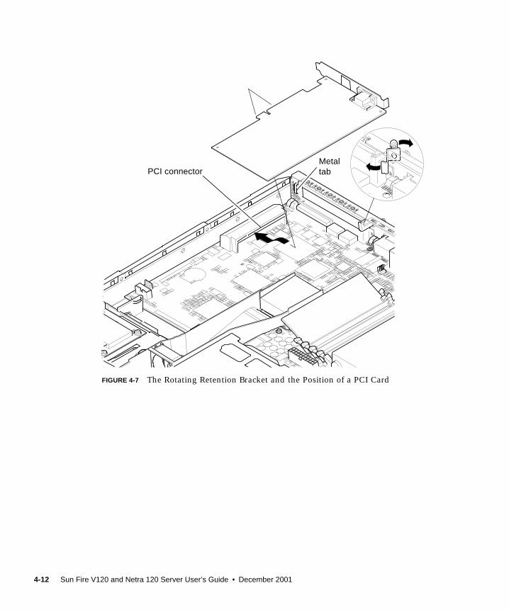
FIGURE 4-7 The Rotating Retention Bracket and the Position of a PCI Card
PCI connectorMetaltab
4-12 Sun Fire V120 and Netra 120 Server User’s Guide • December 2001
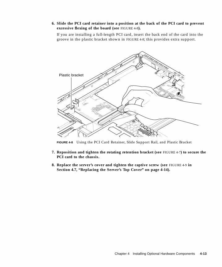
6. Slide the PCI card retainer into a position at the back of the PCI card to preventexcessive flexing of the board (see FIGURE 4-8).
If you are installing a full-length PCI card, insert the back end of the card into the
groove in the plastic bracket shown in FIGURE 4-8; this provides extra support.
FIGURE 4-8 Using the PCI Card Retainer, Slide Support Rail, and Plastic Bracket
7. Reposition and tighten the rotating retention bracket (see FIGURE 4-7) to secure thePCI card to the chassis.
8. Replace the server’s cover and tighten the captive screw (see FIGURE 4-9 inSection 4.7, “Replacing the Server’s Top Cover” on page 4-14).
Plastic bracket
Chapter 4 Installing Optional Hardware Components 4-13

4.6.2 Removing a PCI Card
1. Remove the top cover by following the procedure described in “Opening theServer” on page 4-4.
Make sure you wear an antistatic wrist strap and that you disconnect all power
cables.
2. Loosen the captive screw that secures the rotating retention bracket (the screw andbracket are illustrated in FIGURE 4-7).
Rotate the retention bracket through 90 degrees (see FIGURE 4-7).
3. Move the PCI card retainer along the PCI slide support rail until it is no longertouching the PCI card (see FIGURE 4-8).
4. Remove the PCI card from the PCI connector.
5. Replace the filler panel that protects the pins in the PCI connector.
6. Replace the filler panel for the PCI slot (in the back panel of the chassis), andtighten the captive screw that secures the rotating retention bracket (seeFIGURE 4-7).
7. Replace the server cover and tighten the captive screw (see FIGURE 4-9 inSection 4.7, “Replacing the Server’s Top Cover” on page 4-14).
4.7 Replacing the Server’s Top CoverWhen you have finished installing an option module, replace the server’s top cover.
1. Lower the lid onto the server with the indented arrows on the lid and side of theserver lining up.
2. Slide the lid home towards the front of the server.
3. Tighten the captive retaining screw at the rear (see FIGURE 4-9).
4-14 Sun Fire V120 and Netra 120 Server User’s Guide • December 2001

FIGURE 4-9 Replacing the Top Cover
What’s Next?
When you have installed the optional hardware components you need, go to
Chapter 5 for information about installing the Sun Fire V120 and Netra 120 servers
into a rack.
Alignment arrows
Chapter 4 Installing Optional Hardware Components 4-15

4-16 Sun Fire V120 and Netra 120 Server User’s Guide • December 2001

CHAPTER 5
Installing the Server Into a Rack
This chapter tells you how to install a Sun Fire V120 or Netra 120 server into a rack.
The chapter contains the following sections:
■ Section 5.1, “Installing Into a 19-Inch Four-Post Rack” on page 5-2
■ Section 5.2, “Installing Into a Two-Post Relay Rack” on page 5-12
5-1

5.1 Installing Into a 19-Inch Four-Post Rack
5.1.1 The 19-Inch Rackmounting Kit
The mounting slides can each be used on either side of the rack. The parts required
are listed in TABLE 5-1. The part number of the rackmounting kit is X6919A (see
Section 1.3, “Optional Hardware and Software” on page 1-5).
A bracket is provided to aid cable management at the back of the server (see
FIGURE 5-1).
FIGURE 5-1 Cable Management Bracket
TABLE 5-1 19-inch Rackmounting Kit
Item Quantity Part No.
Front slide 2 340-6125
Rear slide 2 340-6234
Cable management bracket 1 340-6151
M4 nuts 4 240-1373
Rack screw kit 1 565-1645
5-2 Sun Fire V120 and Netra 120 Server User’s Guide • December 2001
5.1.2 Assembling the Slides and Mounting the Server
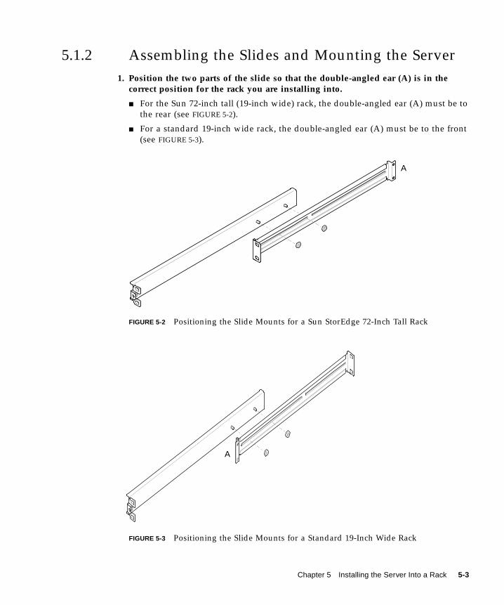
1. Position the two parts of the slide so that the double-angled ear (A) is in thecorrect position for the rack you are installing into.
■ For the Sun 72-inch tall (19-inch wide) rack, the double-angled ear (A) must be to
the rear (see FIGURE 5-2).
■ For a standard 19-inch wide rack, the double-angled ear (A) must be to the front
(see FIGURE 5-3).
FIGURE 5-2 Positioning the Slide Mounts for a Sun StorEdge 72-Inch Tall Rack
FIGURE 5-3 Positioning the Slide Mounts for a Standard 19-Inch Wide Rack
A
A
Chapter 5 Installing the Server Into a Rack 5-3
2. Loosely screw the two parts of the slide mounts together, using the M4 nutssupplied.
3. Measure the distance between the front and back posts of your rack.
4. Adjust the slide mounts so that the distance between the front and back mountingears is approximately the distance between the front and back posts of the rack.
5. Move the brackets so that the studs are in suitable slots, and tighten the nuts.
6. Fasten the mounting slides to the rack, using the screws supplied.
For the Sun StorEdge 72-inch rack, refer to FIGURE 5-4 and FIGURE 5-5. Leave the
screws slightly loose to allow adjustment when you slide the server into the rack.
For a standard 19-inch rack, refer to FIGURE 5-6. Leave the screws slightly loose to
allow adjustment when you slide the server into the rack.
5-4 Sun Fire V120 and Netra 120 Server User’s Guide • December 2001
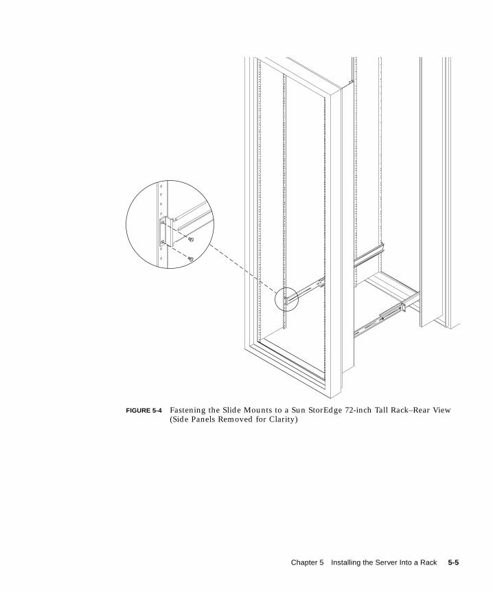
FIGURE 5-4 Fastening the Slide Mounts to a Sun StorEdge 72-inch Tall Rack–Rear View(Side Panels Removed for Clarity)
Chapter 5 Installing the Server Into a Rack 5-5
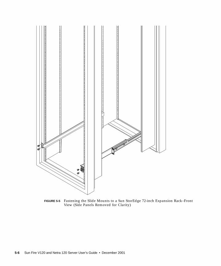
FIGURE 5-5 Fastening the Slide Mounts to a Sun StorEdge 72-inch Expansion Rack–FrontView (Side Panels Removed for Clarity)
5-6 Sun Fire V120 and Netra 120 Server User’s Guide • December 2001
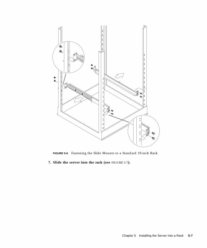
FIGURE 5-6 Fastening the Slide Mounts to a Standard 19-inch Rack
7. Slide the server into the rack (see FIGURE 5-7).
Chapter 5 Installing the Server Into a Rack 5-7

FIGURE 5-7 Sliding the Server Into a Standard 19-Inch Rack
5-8 Sun Fire V120 and Netra 120 Server User’s Guide • December 2001

8. Align the server so that the thumbscrews on its sides fit into the slide mounts inthe rack (see FIGURE 5-8).
If necessary, readjust the slide mounts so that the server aligns correctly. This job is
easier with the thumbscrews done up finger-tight.
FIGURE 5-8 Adjusting the Slide Mounts and Screwing the Server Into the Rack
9. Tighten the slide mounts in the rack.
10. Use a screwdriver to tighten the thumbscrews on the side of the server.
The server is now securely installed in the rack.
Chapter 5 Installing the Server Into a Rack 5-9
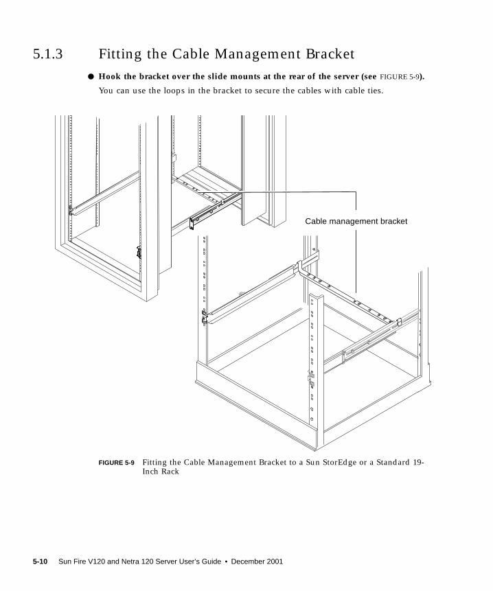
5.1.3 Fitting the Cable Management Bracket
● Hook the bracket over the slide mounts at the rear of the server (see FIGURE 5-9).
You can use the loops in the bracket to secure the cables with cable ties.
FIGURE 5-9 Fitting the Cable Management Bracket to a Sun StorEdge or a Standard 19-Inch Rack
Cable management bracket
5-10 Sun Fire V120 and Netra 120 Server User’s Guide • December 2001

5.1.4 Tips for Using a Sun StorEdge 72-inch Rack■ For maximum stability, fill the rack from the bottom up and leave at least 4U of
space free at the top.
■ To prevent warm air flowing to the front of the rack and being recirculated (which
would reduce the efficiency of your cooling system and potentially cause
overheating), close off the empty spaces at the top of the rack with filler panels.
The following filler panels are available from your local Sun sales representative:
■ 1U (part number: 330-2610-01)
■ 2U (part number: 330-2611-01)
■ 3U (part number: 330-2613-01)
■ 4U (part number: 330-2614-01)
■ 5U (part number: 330-2615-01)
■ Position your racks so that the warm air exhaust from one rack does not flow
directly into the cool air intake area for another.
■ If space is limited at the back of your Sun StorEdge 72-inch rack, install a
redundant fan tray (part number: X9819A) into the top of the rack. This pulls air
up through the top of the rack to prevent the build-up of heat behind it.
What’s Next?
When you have installed your server into the rack, go to Chapter 6 for information
about connecting the cables and setting up serial connections.
Chapter 5 Installing the Server Into a Rack 5-11
5.2 Installing Into a Two-Post Relay Rack
5.2.1 The Fixed Mounting Bracket Kit
The parts you require are listed in TABLE 5-2.
5.2.2 Attaching the Fixed-Mounting Brackets
1. Remove the thumbscrew rackmounting brackets from either side of the server (seeFIGURE 5-10).
FIGURE 5-10 Removing the Thumbscrew Brackets
TABLE 5-2 Fixed Mounting Bracket Kit
Item Quantity Part No.
Brackets 4 340-5819
M4 x 8-mm countersunk Phillips screw kit 1 565-1654
5-12 Sun Fire V120 and Netra 120 Server User’s Guide • December 2001
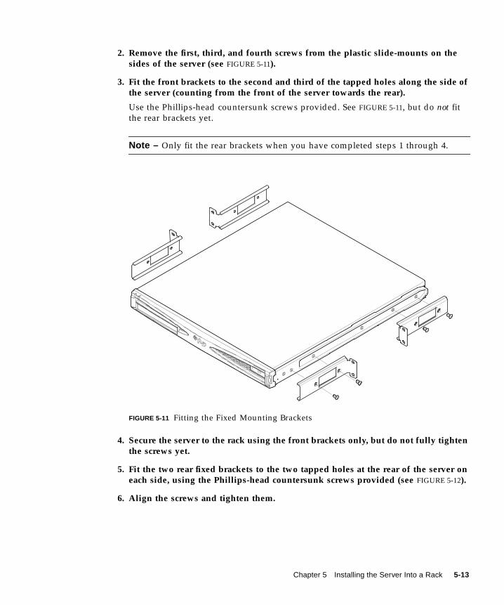
2. Remove the first, third, and fourth screws from the plastic slide-mounts on thesides of the server (see FIGURE 5-11).
3. Fit the front brackets to the second and third of the tapped holes along the side ofthe server (counting from the front of the server towards the rear).
Use the Phillips-head countersunk screws provided. See FIGURE 5-11, but do not fit
the rear brackets yet.
Note – Only fit the rear brackets when you have completed steps 1 through 4.
FIGURE 5-11 Fitting the Fixed Mounting Brackets
4. Secure the server to the rack using the front brackets only, but do not fully tightenthe screws yet.
5. Fit the two rear fixed brackets to the two tapped holes at the rear of the server oneach side, using the Phillips-head countersunk screws provided (see FIGURE 5-12).
6. Align the screws and tighten them.
Chapter 5 Installing the Server Into a Rack 5-13

FIGURE 5-12 The Server Installed in a Two-Post Rack
What’s Next?
When you have installed the server into the rack, go to Chapter 6 for information
about connecting the cables and setting up serial connections.
5-14 Sun Fire V120 and Netra 120 Server User’s Guide • December 2001
CHAPTER 6
Connecting the Cables
This chapter describes how to connect the power cables and the Ethernet and serial
cables to the Sun Fire V120 and Netra 120 servers. It also tells you how to set up the
serial connections you need.
Make sure you have installed the server into a rack or cabinet (see Chapter 5) before
following the instructions in this chapter.
This chapter contains the following sections:
■ Section 6.1, “Connecting the Cables to the Server” on page 6-2
■ Section 6.2, “Using a Single DC Power Cord” on page 6-4
■ Section 6.3, “Setting Up Serial Connections” on page 6-4
■ Section 6.4, “Connecting to Your Server From a Laptop Running Microsoft
Windows” on page 6-10
6-1

6.1 Connecting the Cables to the Server
FIGURE 6-1 Connecting the Cables to the Sun Fire V120 Server
FIGURE 6-2 Connecting the Cables to the Netra 120 Server
AC powercable Ethernet
links
Seriallinks
DB-25 adapterDB-25 adapter
SCSI adapter
DB-25 adapter
DC powercable Ethernet
links
Seriallinks
SCSI adapter
6-2 Sun Fire V120 and Netra 120 Server User’s Guide • December 2001
Before following the instructions in this section, make sure you have installed the
server into a rack or cabinet (see Chapter 5).
1. Connect the power cord or cords.
2. Connect the server to at least one Ethernet hub.
You can connect to a maximum of two Ethernet hubs (unless you have a PCI adapter
installed).
3. Connect a serial device to the Serial A/LOM port.
To use the server’s remote monitoring and management facilities, you must use the
port labeled Serial A/LOM. For more information about remote monitoring and
management, see Chapter 8 and Chapter 9.
If you intend to configure the server directly from a dumb terminal or a Sun
workstation, insert the loose end of the serial cable into the DB-25 adapter supplied
(see FIGURE 6-1 and FIGURE 6-2). Then plug the adapter into the DB-25 serial
connector on the terminal or Sun workstation you intend to use.
For more information, see Section 6.3, “Setting Up Serial Connections” on page 6-4.
4. If you need to connect the server to an external SCSI device, you will need to usethe SCSI cable supplied with that device.
The server’s external SCSI bus is compatible with SCSI devices of the following
types:
■ Single Ended (SE)
■ Low Voltage Differential (LVD)
■ Narrow (8-bit)
■ Wide (16-bit)
Caution – AC-powered Sun products are designed to work with single-phase
power systems that have a grounded neutral conductor. To reduce the risk of electric
shock, do not plug Sun products into any other type of power system. Contact your
facilities manager or a qualified electrician if you are not sure what type of power is
supplied to your building.
Caution – Your AC-powered Sun product is shipped with a grounding type (three-
wire) power cord. To reduce the risk of electric shock, always plug the cord into a
grounded outlet.
Chapter 6 Connecting the Cables 6-3

6.2 Using a Single DC Power CordIf you are using a Netra 120 server and you have only one DC power cord connected
to the server, the LOM generates a power-on event, but it also generates an inlet
failure event and causes the fault indicator to be lit and to remain lit.
Similarly, if you remove a single DC power cord from a Netra 120 server that is
powered on, the LOM generates an inlet failure event and causes the fault indicator
to be lit and to remain lit.
If you intend to run the Netra 120 server using only one DC supply cord, then ignore
these inlet failure events and turn off the fault indicator by typing:
6.3 Setting Up Serial ConnectionsTo perform the initial configuration when you install a Sun Fire V120 or Netra 120
server, and also for ongoing monitoring and management of the server, you will
need to use at least one of the serial ports on the server’s back panel. You can
connect either or both serial ports to any of the following devices:
■ Dumb terminalFor this connection, you can use the standard RJ-45 patch cable supplied with the
server, but you need to insert one end into the DB-25 adapter also supplied.
■ Sun workstationFor this connection, you can use the standard RJ-45 patch cable supplied with the
server, but you need to insert one end into the DB-25 adapter also supplied.
■ Terminal server (or patch panel connected to a terminal server)The pinouts for the server’s serial ports correspond with the pinouts for the RJ-45
ports on the Cisco AS2511-RJ Terminal Server. For terminal servers from other
manufacturers, you may need to make your own roll-over cable (see Section 6.3.1,
“Connecting to a Terminal Server” on page 6-5).
■ ModemFor this connection, you can use the standard RJ-45 patch cable supplied with the
server, but you need to insert one end into the DB-25 adapter also supplied.
lom> faultoff
6-4 Sun Fire V120 and Netra 120 Server User’s Guide • December 2001
Note – Do not use the Serial A/LOM port for binary data transfers. To perform
anything other than ASCII transfers, use the port labeled Serial B.
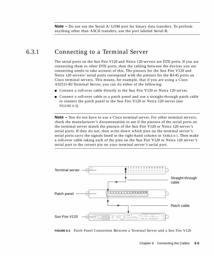
6.3.1 Connecting to a Terminal Server
The serial ports on the Sun Fire V120 and Netra 120 servers are DTE ports. If you are
connecting them to other DTE ports, then the cabling between the devices you are
connecting needs to take account of this. The pinouts for the Sun Fire V120 and
Netra 120 servers’ serial ports correspond with the pinouts for the RJ-45 ports on
Cisco terminal servers. This means, for example, that if you are using a Cisco
AS2511-RJ Terminal Server, you can do either of the following:
■ Connect a roll-over cable directly to the Sun Fire V120 or Netra 120 server.
■ Connect a roll-over cable to a patch panel and use a straight-through patch cable
to connect the patch panel to the Sun Fire V120 or Netra 120 server (see
FIGURE 6-3).
Note – You do not have to use a Cisco terminal server. For other terminal servers,
check the manufacturer’s documentation to see if the pinouts of the serial ports on
the terminal server match the pinouts of the Sun Fire V120 or Netra 120 server’s
serial ports. If they do not, then write down which pins on the terminal server’s
serial ports carry the signals listed in the right-hand column in TABLE 6-1. Then make
a roll-over cable taking each of the pins on the Sun Fire V120 or Netra 120 server’s
serial port to the correct pin on your terminal server’s serial port.
FIGURE 6-3 Patch Panel Connection Between a Terminal Server and a Sun Fire V120
1 2 3 4 5 6 7 8 9 10 11 12 13 14 15
1 2 3 4 5 6 7 8 9 10 11 12 13 14 15
Terminal server
Patch panel
Sun Fire V120
Straight-throughcable
Patch cable
Chapter 6 Connecting the Cables 6-5

Note – When the Sun Fire V120 and Netra 120 servers are viewed from the rear, pin
1 of the RJ-45 serial port is on the left, and pin 8 is on the right.
FIGURE 6-4 Pins 1 to 8 on the Serial Port
TABLE 6-1 Serial Port Connection to a Terminal Server
Pin number on Sun FireV120 and Netra 120
Signal Signal to connect to on theTerminal Server
Pin 1 RTS CTS
Pin 2 DTR DSR
Pin 3 TXD RXD
Pin 4 Signal Ground Signal Ground
Pin 5 Signal Ground Signal Ground
Pin 6 RXD TXD
Pin 7 DSR DTR
Pin 8 CTS RTS
81
6-6 Sun Fire V120 and Netra 120 Server User’s Guide • December 2001

6.3.2 Using a DB-25 Adapter for Your Serial Link
The pinouts are identical for both of the RJ-45 serial ports on the rear panel of your
server. To connect from a VT100 terminal, you need to use either the DB-25 (25-Pin
DSUB male to 8-POS RJ-45 female) adapter supplied by Sun (part number 530-2889)
with your server or an alternative adapter that performs the same pin inter-
connections. The Sun-supplied DB-25 adapter enables you to connect to any Sun
system. The pin inter-connections it performs are listed in TABLE 6-2.
Note – When the Sun Fire V120 and Netra 120 servers are viewed from the rear, pin
1 of the RJ-45 serial port is on the left, and pin 8 is on the right.
FIGURE 6-5 Pins 1 to 8 on the Serial Ports
TABLE 6-2 Pin Inter-connections Performed by the Sun DB-25 (25-pin) Adapter
Serial Port (RJ-45 Connector) Pin 25-pin Connector
Pin 1 (RTS) Pin 5 (CTS)
Pin 2 (DTR) Pin 6 (DSR)
Pin 3 (TXD) Pin 3 (RXD)
Pin 4 (Signal Ground) Pin 7 (Signal Ground)
Pin 5 (Signal Ground) Pin 7 (Signal Ground)
Pin 6 (RXD) Pin 2 (TXD)
Pin 7 (DSR) Pin 20 (DTR)
Pin 8 (CTS) Pin 4 (RTS)
81
Chapter 6 Connecting the Cables 6-7
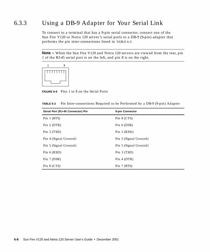
6.3.3 Using a DB-9 Adapter for Your Serial Link
To connect to a terminal that has a 9-pin serial connector, connect one of the
Sun Fire V120 or Netra 120 server’s serial ports to a DB-9 (9-pin) adapter that
performs the pin inter-connections listed in TABLE 6-3.
Note – When the Sun Fire V120 and Netra 120 servers are viewed from the rear, pin
1 of the RJ-45 serial port is on the left, and pin 8 is on the right.
FIGURE 6-6 Pins 1 to 8 on the Serial Ports
TABLE 6-3 Pin Inter-connections Required to be Performed by a DB-9 (9-pin) Adapter
Serial Port (RJ-45 Connector) Pin 9-pin Connector
Pin 1 (RTS) Pin 8 (CTS)
Pin 2 (DTR) Pin 6 (DSR)
Pin 3 (TXD) Pin 2 (RXD)
Pin 4 (Signal Ground) Pin 5 (Signal Ground)
Pin 5 (Signal Ground) Pin 5 (Signal Ground)
Pin 6 (RXD) Pin 3 (TXD)
Pin 7 (DSR) Pin 4 (DTR)
Pin 8 (CTS) Pin 7 (RTS)
81
6-8 Sun Fire V120 and Netra 120 Server User’s Guide • December 2001

6.3.4 Settings for the Serial Connections
The settings you need to use for a serial connection are listed in TABLE 6-4. If you
need to perform binary data transfers (that is, transfers of anything other than
simple ASCII character streams), use the Serial B port. Communication on the Serial
A/LOM port is subject to interruption by the Lights-Out Management device (see
Chapter 8).
Note – If you ever change the OpenBoot PROM’s serial configuration and then
restart the server, the LOM device’s serial configuration will reflect the new settings.
By default, however, both the OpenBoot PROM and the LOM serial configuration
are as described in TABLE 6-4.
TABLE 6-4 Default Settings for Connecting to the Serial A/LOM or Serial B Port
Parameter Setting
Connector Serial A/LOM or Serial B (use Serial B for binary data transfers)
Rate 9600 baud
Parity No
Stop bits 1
Data bits 8
Chapter 6 Connecting the Cables 6-9
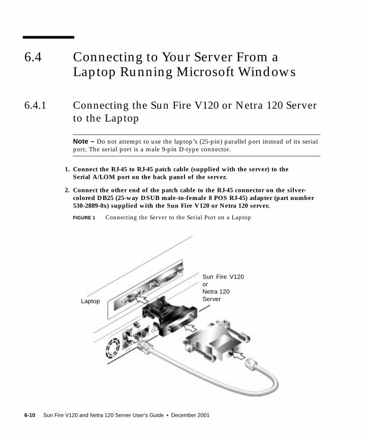
6.4 Connecting to Your Server From aLaptop Running Microsoft Windows
6.4.1 Connecting the Sun Fire V120 or Netra 120 Server
to the Laptop
Note – Do not attempt to use the laptop’s (25-pin) parallel port instead of its serial
port. The serial port is a male 9-pin D-type connector.
1. Connect the RJ-45 to RJ-45 patch cable (supplied with the server) to theSerial A/LOM port on the back panel of the server.
2. Connect the other end of the patch cable to the RJ-45 connector on the silver-colored DB25 (25-way DSUB male-to-female 8 POS RJ-45) adapter (part number530-2889-0x) supplied with the Sun Fire V120 or Netra 120 server.
FIGURE 1 Connecting the Server to the Serial Port on a Laptop
Laptop
Sun Fire V120orNetra 120Server
6-10 Sun Fire V120 and Netra 120 Server User’s Guide • December 2001
3. Next connect the 25-way D-type male connector to an adapter that has one 25-wayfemale connector and one 9-way D-type female connector.
Sun does not supply a 25x9-way D-type female-to-female adapter. However,
adapters like this are available from home computer suppliers and electronics stores.
The pin inter-connections that the adapter must perform are listed in TABLE 6-3.
4. Finally, connect the 9-way female connector to the serial port on the laptop.
6.4.2 Using Microsoft Windows HyperTerminal
Note – If you normally connect the serial port on your laptop to a handheld device,
you must close the Hot Sync Manager before following the instructions in this
section. Otherwise you will not be able to use the serial port to communicate with
the Sun Fire V120 or Netra 120 server.
The instructions in this section were verified on a laptop PC running Microsoft
Windows 98 and with HyperTerminal Applet version 3.0.
1. Run the Windows HyperTerminal utility.
2. In the HyperTerminal window, double-click the Hyperttrm.exe icon.
TABLE 6-5 Pin Inter-connections Required to be Performed by the 25x9-way D-typeFemale-to-Female Adapter
9-way Female Connector 25-way Female Connector
Pin 1 Pin 8
Pin 2 Pin 3
Pin 3 Pin 2
Pin 4 Pin 20
Pin 5 Pin 7
Pin 6 Pin 6
Pin 7 Pin 4
Pin 8 Pin 5
Pin 9 Pin 22
Chapter 6 Connecting the Cables 6-11
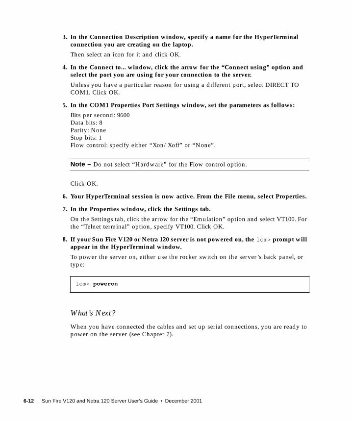
3. In the Connection Description window, specify a name for the HyperTerminalconnection you are creating on the laptop.
Then select an icon for it and click OK.
4. In the Connect to... window, click the arrow for the “Connect using” option andselect the port you are using for your connection to the server.
Unless you have a particular reason for using a different port, select DIRECT TO
COM1. Click OK.
5. In the COM1 Properties Port Settings window, set the parameters as follows:
Bits per second: 9600
Data bits: 8
Parity: None
Stop bits: 1
Flow control: specify either “Xon/Xoff” or “None”.
Note – Do not select “Hardware” for the Flow control option.
Click OK.
6. Your HyperTerminal session is now active. From the File menu, select Properties.
7. In the Properties window, click the Settings tab.
On the Settings tab, click the arrow for the “Emulation” option and select VT100. For
the “Telnet terminal” option, specify VT100. Click OK.
8. If your Sun Fire V120 or Netra 120 server is not powered on, the lom> prompt willappear in the HyperTerminal window.
To power the server on, either use the rocker switch on the server’s back panel, or
type:
What’s Next?
When you have connected the cables and set up serial connections, you are ready to
power on the server (see Chapter 7).
lom> poweron
6-12 Sun Fire V120 and Netra 120 Server User’s Guide • December 2001
CHAPTER 7
Powering On the Sun Fire V120 orNetra 120 Server
This chapter tells you how to connect to and power on the Sun Fire V120 or Netra
120 server.
The chapter contains the following sections:
■ Section 7.1, “Preparing to Configure the Server” on page 7-2
■ Section 7.2, “Powering On the Server” on page 7-3
■ Section 7.3, “Using the Power (On/Standby) Switch” on page 7-7
7-1

7.1 Preparing to Configure the ServerTo perform the initial configuration of the Sun Fire V120 or Netra 120 server, set up
a serial connection using the port labeled Serial A/LOM on the server’s back panel
(see Chapter 6). Make sure you have the server’s power cord(s) connected (see
Chapter 6).
7.1.1 Using a Terminal Server
● To access the Sun Fire V120 or Netra 120 server from a Sun workstation through aterminal server, open a terminal session on the Sun workstation and type:
For example, for a Sun Fire V120 server connected to port 10000 on a terminal server
whose IP address is 192.20.30.10, you would type:
7.1.2 Configuring From a Terminal or Workstation
● To access the server from a dumb terminal, set up a connection between theterminal and the server.
● To access the server from a Sun workstation that is directly connected to theserver, set up the connections between the devices, then open a terminal sessionand type:
The tip command above assumes that your console is using its ttya port. If you
later configure your console to use its ttyb port, you will need to type the following
to set up a tip session:
# telnet IP-address-of-terminal-server port-number
# telnet 192.20.30.10 10000
# tip /dev/term/a -9600
# tip /dev/term/b -9600
7-2 Sun Fire V120 and Netra 120 Server User’s Guide • December 2001
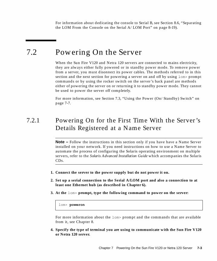
For information about dedicating the console to Serial B, see Section 8.6, “Separating
the LOM From the Console on the Serial A/LOM Port” on page 8-19).
7.2 Powering On the ServerWhen the Sun Fire V120 and Netra 120 servers are connected to mains electricity,
they are always either fully powered or in standby power mode. To remove power
from a server, you must disonnect its power cables. The methods referred to in this
section and the next section for powering a server on and off by using lom> prompt
commands or by using the rocker switch on the server’s back panel are methods
either of powering the server on or returning it to standby power mode. They cannot
be used to power the server off completely.
For more information, see Section 7.3, “Using the Power (On/Standby) Switch” on
page 7-7.
7.2.1 Powering On for the First Time With the Server’s
Details Registered at a Name Server
Note – Follow the instructions in this section only if you have have a Name Server
installed on your network. If you need instructions on how to use a Name Server to
automate the process of configuring the Solaris operating environment on multiple
servers, refer to the Solaris Advanced Installation Guide which accompanies the Solaris
CDs.
1. Connect the server to the power supply but do not power it on.
2. Set up a serial connection to the Serial A/LOM port and also a connection to atleast one Ethernet hub (as described in Chapter 6).
3. At the lom> prompt, type the following command to power on the server:
For more information about the lom> prompt and the commands that are available
from it, see Chapter 8.
4. Specify the type of terminal you are using to communicate with the Sun Fire V120or Netra 120 server.
lom> poweron
Chapter 7 Powering On the Sun Fire V120 or Netra 120 Server 7-3
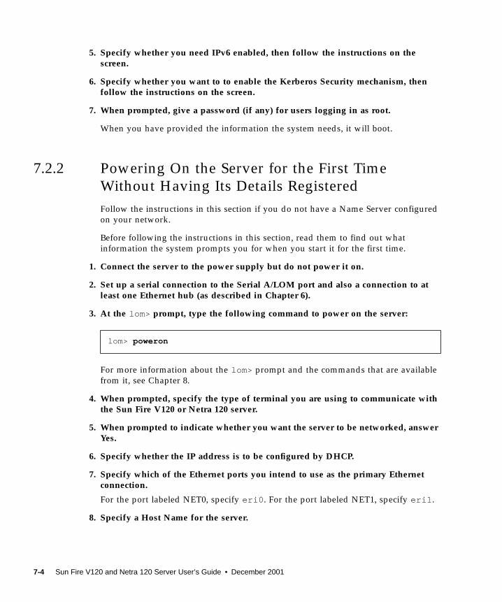
5. Specify whether you need IPv6 enabled, then follow the instructions on thescreen.
6. Specify whether you want to to enable the Kerberos Security mechanism, thenfollow the instructions on the screen.
7. When prompted, give a password (if any) for users logging in as root.
When you have provided the information the system needs, it will boot.
7.2.2 Powering On the Server for the First Time
Without Having Its Details Registered
Follow the instructions in this section if you do not have a Name Server configured
on your network.
Before following the instructions in this section, read them to find out what
information the system prompts you for when you start it for the first time.
1. Connect the server to the power supply but do not power it on.
2. Set up a serial connection to the Serial A/LOM port and also a connection to atleast one Ethernet hub (as described in Chapter 6).
3. At the lom> prompt, type the following command to power on the server:
For more information about the lom> prompt and the commands that are available
from it, see Chapter 8.
4. When prompted, specify the type of terminal you are using to communicate withthe Sun Fire V120 or Netra 120 server.
5. When prompted to indicate whether you want the server to be networked, answerYes.
6. Specify whether the IP address is to be configured by DHCP.
7. Specify which of the Ethernet ports you intend to use as the primary Ethernetconnection.
For the port labeled NET0, specify eri0 . For the port labeled NET1, specify eri1 .
8. Specify a Host Name for the server.
lom> poweron
7-4 Sun Fire V120 and Netra 120 Server User’s Guide • December 2001

9. If prompted, specify the IP address for the system.
The system prompts you for this address if you declined to use DHCP in Step 6. It
also asks you whether the server is to be part of a subnet, and if you answer Yes it
prompts you to provide the netmask of the subnet.
10. Specify whether you need IPv6 enabled, then follow the instructions on thescreen.
11. Specify whether you want to to enable the Kerberos Security mechanism, thenfollow the instructions on the screen.
12. Specify the Name Service you want the server to use.
13. Specify the name of the Domain that the server will be part of.
14. Specify whether you want the system to search the network for a Name Server orto use a particular Name Server.
15. If you chose to use a particular Name Server, specify the Host Name and IPaddress of the Name Server, and then confirm the information you have provided.
16. Now go to the Name Server, and create entries in its network administration filesfor the system you have just been setting up.
17. When you come back to the system you are setting up, you will be prompted forthe time and date information the system needs.
18. Finally, when prompted, give a password (if any) for users logging in as root.
When you have provided the information the system needs, it will boot.
7.2.3 Powering On a Standalone Server for the First
Time
1. Connect the server to the power supply but do not power it on.
2. Set up a serial connection using the Serial A/LOM port (as described inChapter 6).
3. At the lom> prompt, type the following command to power on the server:
For more information about the lom> prompt and the commands that are available
from it, see Chapter 8.
lom> poweron
Chapter 7 Powering On the Sun Fire V120 or Netra 120 Server 7-5
4. When prompted, specify the type of terminal you are using to communicate withthe server.
5. When prompted to indicate whether you want the server to be networked, specifyNo.
6. Specify a Host Name for the server.
7. Confirm the information you have given.
8. Specify the date and time information the system needs.
9. When prompted, give a password (if any) for users logging in as root.
When you have provided the information the system needs, it will boot.
7.2.4 Clearing Your Configuration and Starting Again
If you need to clear the configuration of the server so that you can start the power on
process again as if from a previously unused server, follow the instructions below:
1. Boot the server into Solaris by typing:
2. At the Solaris prompt, type:
3. When prompted to confirm that you want to create a “blank” server, type y.
4. When the server has unconfigured itself, it displays the ok prompt.
To reconfigure it, first power down the system by typing the following:
5. Then follow the instructions in either of the following sections:
■ Section 7.2.1, “Powering On for the First Time With the Server’s Details
Registered at a Name Server” on page 7-3 or
■ Section 7.2.2, “Powering On the Server for the First Time Without Having Its
Details Registered” on page 7-4.
ok boot
# sys-unconfig
ok power-off
7-6 Sun Fire V120 and Netra 120 Server User’s Guide • December 2001
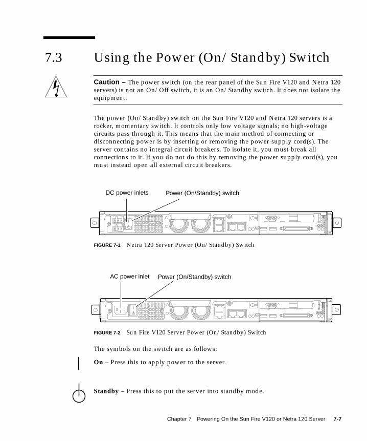
7.3 Using the Power (On/Standby) Switch
Caution – The power switch (on the rear panel of the Sun Fire V120 and Netra 120
servers) is not an On/Off switch, it is an On/Standby switch. It does not isolate the
equipment.
The power (On/Standby) switch on the Sun Fire V120 and Netra 120 servers is a
rocker, momentary switch. It controls only low voltage signals; no high-voltage
circuits pass through it. This means that the main method of connecting or
disconnecting power is by inserting or removing the power supply cord(s). The
server contains no integral circuit breakers. To isolate it, you must break all
connections to it. If you do not do this by removing the power supply cord(s), you
must instead open all external circuit breakers.
FIGURE 7-1 Netra 120 Server Power (On/Standby) Switch
FIGURE 7-2 Sun Fire V120 Server Power (On/Standby) Switch
The symbols on the switch are as follows:
On – Press this to apply power to the server.
Standby – Press this to put the server into standby mode.
DC power inlets Power (On/Standby) switch
AC power inlet Power (On/Standby) switch
Chapter 7 Powering On the Sun Fire V120 or Netra 120 Server 7-7
What’s Next?
When you have powered on the server and booted and logged in, your server is
ready to use.
For information about managing the server, see Chapter 8 and Chapter 9.
7-8 Sun Fire V120 and Netra 120 Server User’s Guide • December 2001
PART II Remote and Local Management


CHAPTER 8
Managing the Server From the lom>Prompt
This chapter introduces the LOM Lights-Out Management facilities available for the
Sun Fire V120 and Netra 120 servers and tells you how to use the /usr/sbin/lomutility which provides a user interface to the device.
The chapter contains the following sections:
■ Section 8.1, “Introduction to Lights-Out Management” on page 8-2
■ Section 8.2, “Powering On or Resetting the Server From the LOM Shell” on
page 8-3
■ Section 8.3, “Monitoring the Server From the LOM Shell” on page 8-8
■ Section 8.4, “Setting Up LOM Privileges for Named Users” on page 8-13
■ Section 8.5, “Setting the LOM Device’s Configurable Variables” on page 8-17
■ Section 8.6, “Separating the LOM From the Console on the Serial A/LOM Port”
on page 8-19
■ Section 8.7, “Viewing the Event Reports That the LOM Sends to syslogd” on
page 8-20
■ Section 8.8, “The LOM Shell Command List” on page 8-21
■ Section 8.9, “Checking the Status of the Server’s Fans” on page 8-23
Note – For information about configuring the LOM device to restart the server
automatically in the event of a lockup, see Chapter 9.
Note – For information about how to configure the LOM device-driver, see
Appendix C.
8-1

8.1 Introduction to Lights-Out ManagementThe system board in the Sun Fire V120 and Netra 120 servers contains a LOM device
(see FIGURE 8-1). This device provides management facilities that enable you to detect
and respond quickly to problems. The facilities are particularly useful for managing
servers that are deployed in a “lights out” environment. However, you can also use
them to perform quick onsite management tasks at a locally connected terminal.
You can use the LOM facilities remotely or from a local connection to:
■ Power the server on or down to standby mode.
■ Monitor the server’s temperature and the status of its power supply, fans, supply
rails, fault LED and alarms, even when the server is in standby mode.
■ Turn a Fault LED on.
■ Configure the server to restart automatically after a lockup (see Chapter 9).
FIGURE 8-1 The Location of the Lights-Out Management Device on the System Board
LOM device
8-2 Sun Fire V120 and Netra 120 Server User’s Guide • December 2001

Note – The Sun Fire V120 and Netra 120 servers are supplied with the Solaris
operating environment installed and with the supplementary Lights-Out
Management (LOM) software described in this chapter and Chapter 9 also installed.
This software enables you to manage the server locally or remotely. If you ever need
to re-install Solaris and you want to use the Lights-Out Management facilities, you
must also
re-install the Lights-Out Management software from the CD entitled SoftwareSupplement for the Solaris Operating Environment. This CD is included with the Solaris
media kit. For the location of the LOM packages on the CD, refer to the SolarisHardware Platform Guide for the release of Solaris that you are using.
8.2 Powering On or Resetting the ServerFrom the LOM ShellTo use the Lights-Out Management facilities either remotely or locally, you need a
terminal connection to the Serial A/LOM port on the back of the server (see
Chapter 6).
There are two ways of interrogating the LOM device or of sending it commands to
perform. One is by executing LOM commands from the lom> shell prompt. This
chapter tells you how to do this. The other is by executing LOM-specific Solaris
commands from the console prompt. For information about the LOM commands
available with the Solaris operating environment, see Chapter 9.
When the Sun Fire V120 and Netra 120 servers are connected to a power source, they
are always either fully powered or in standby power mode. To remove power
entirely from these servers you must disonnect their power cables or open all
external circuit breakers. The methods referred to in this chapter for powering the
servers on and off by using lom> prompt commands are in fact methods either of
powering them on or of returning them to standby power mode. The poweroffcommand described in this chapter does not power a server off completely.
Note – All commands that involve powering on or off, resetting, or specifying the
boot mode of the server require you or the named user to have r -level LOM user
permission. If you have not set up any named users of the LOM device, then you
(and they) have r -level permission by default. If you have set up one or more named
users and you want any of them to use the commands that involve powering on or
off, resetting, or specifying the boot-mode of the server, then you must explicitly
give those users r -level permission. For more information about user privileges, see
Section 8.4, “Setting Up LOM Privileges for Named Users” on page 8-13.
Chapter 8 Managing the Server From the lom> Prompt 8-3

8.2.1 Powering the Server On or Down to Standby
Mode
If the server you are connected to is not powered on but is connected to mains
electricity, you will see the lom> prompt at your terminal. Remember that the LOM
uses standby power and so remains active even when the Sun Fire V120 or Netra 120
server is not powered on.
● To power on the server, type:
● To power the server down to standby mode, type:
8.2.2 Displaying the lom> Prompt
When you connect a terminal to the Serial A/LOM port, you will only see the lom>prompt if the server is powered off. If it is powered on and has not already been put
into LOM mode, it will display the console prompt.
● To display the lom> prompt, type the following LOM escape sequence:
When you type the LOM escape sequence, the LOM device takes control of the Serial
A/LOM port and the lom> prompt appears on your terminal screen. You can type
the LOM escape sequence at any time.
Note – If you are at the console and you type the first character of the LOM escape
sequence (by default this is #), there is a second’s delay before the character appears
on the screen. This is because the server waits to see if you type the dot (.) character
next. If you do, the lom> prompt is displayed. If you do not, the # character appears
on the screen.
For information about changing the first character of the LOM escape sequence, see
Section 9.3.3, “Changing the First Character of the Sequence for Escaping to the
lom> Prompt (lom -X)” on page 9-12.
lom> poweron
lom> poweroff
# #.
8-4 Sun Fire V120 and Netra 120 Server User’s Guide • December 2001
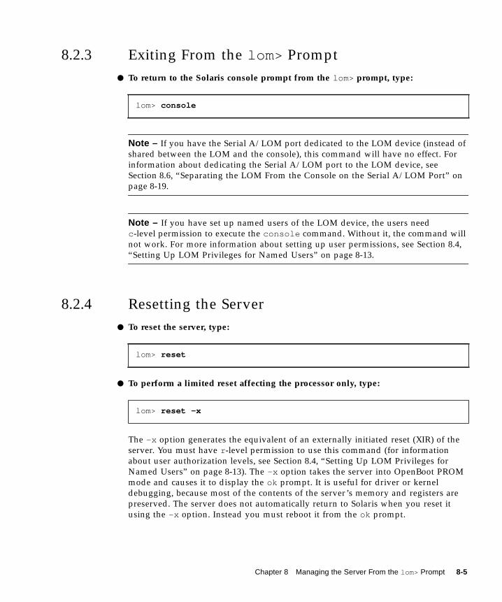
8.2.3 Exiting From the lom> Prompt
● To return to the Solaris console prompt from the lom> prompt, type:
Note – If you have the Serial A/LOM port dedicated to the LOM device (instead of
shared between the LOM and the console), this command will have no effect. For
information about dedicating the Serial A/LOM port to the LOM device, see
Section 8.6, “Separating the LOM From the Console on the Serial A/LOM Port” on
page 8-19.
Note – If you have set up named users of the LOM device, the users need
c -level permission to execute the console command. Without it, the command will
not work. For more information about setting up user permissions, see Section 8.4,
“Setting Up LOM Privileges for Named Users” on page 8-13.
8.2.4 Resetting the Server
● To reset the server, type:
● To perform a limited reset affecting the processor only, type:
The -x option generates the equivalent of an externally initiated reset (XIR) of the
server. You must have r -level permission to use this command (for information
about user authorization levels, see Section 8.4, “Setting Up LOM Privileges for
Named Users” on page 8-13). The -x option takes the server into OpenBoot PROM
mode and causes it to display the ok prompt. It is useful for driver or kernel
debugging, because most of the contents of the server’s memory and registers are
preserved. The server does not automatically return to Solaris when you reset it
using the -x option. Instead you must reboot it from the ok prompt.
lom> console
lom> reset
lom> reset -x
Chapter 8 Managing the Server From the lom> Prompt 8-5

8.2.5 Displaying the ok or kadb Prompt
To display the ok or kadb prompt, type the following at the lom> prompt:
Note – If you have the Serial A/LOM port dedicated to the LOM device, this
command will have no effect. For information about dedicating the Serial A/LOM
port to the LOM device, see Section 8.6, “Separating the LOM From the Console on
the Serial A/LOM Port” on page 8-19. To use the break command, you must have
c -level LOM user privileges. For more information, see Section 8.4, “Setting Up
LOM Privileges for Named Users” on page 8-13.
8.2.6 Controlling the Server’s Booting Behavior
The LOM shell includes a bootmode command:
bootmode [-u][normal|forth|reset_nvram|diag|skip_diag]
This command enables you to dictate the behavior of the server after a reset. Its
functionality is identical to the functionality available on Sun keyboards via the L1
key combinations. (However, the bootmode command is provided because the L1
key combinations are not available for the Sun Fire V120 or Netra 120 server: you
cannot use these key combinations from a keyboard that is connected to the server
via a serial link.)
You must have r -level LOM permission to use the bootmode command. For
information about user privileges, see Section 8.4, “Setting Up LOM Privileges for
Named Users” on page 8-13.
lom> break
8-6 Sun Fire V120 and Netra 120 Server User’s Guide • December 2001

8.2.6.1 Boot Modes Available
If you use the bootmode command without arguments, the LOM device reports just
the current boot mode. The boot modes available are listed in TABLE 8-1.
TABLE 8-1 Boot Modes
Mode Description
-u This option does not represent a boot mode. However, if you have
previously dedicated the Serial A/LOM port to the LOM device
and now want to share the port between the console and the LOM
device, you can use the -u option to achieve this. It is a quick
alternative to the procedure described for sharing the Serial
A/LOM port in the section called “Separating the LOM From the
Console on the Serial A/LOM Port” on page 8-19.
normal In this mode, the server boots using your OpenBootTM PROM
settings. To cause this parameter to take effect, you must reset the
server after executing the bootmode command at the lom> prompt.
forth In this mode, the server does not boot to Solaris but stops the boot
cycle at the ok prompt. The command is equivalent to the L1-F key
combination for Sun keyboards. To cause the parameter to take
effect, you must execute the bootmode forth command at the
lom> prompt and then reset the server. (It is only when the server
resets that it reads the new forth parameter from the LOM device.)
reset_nvram In this mode, the server returns all NVRAM data to its factory-
default setting. The command is equivalent to the L1-N key
combination for Sun keyboards. To cause the parameter to take
effect, you must reset the server after executing the bootmodecommand at the lom> prompt.
diag In this mode, the server performs full self-diagnostics as part of the
boot process. The command is equivalent to the L1-D key
combination for Sun keyboards. To cause the parameter to take
effect, you must power off and then power on the server within 10
minutes after executing the bootmode command at the lom>prompt.
skip_diag In this mode, the server skips the diagnostics part of the boot
process. To cause the parameter to take effect, you must power off
and then power on the server within 10 minutes after executing the
bootmode command at the lom> prompt.
Chapter 8 Managing the Server From the lom> Prompt 8-7
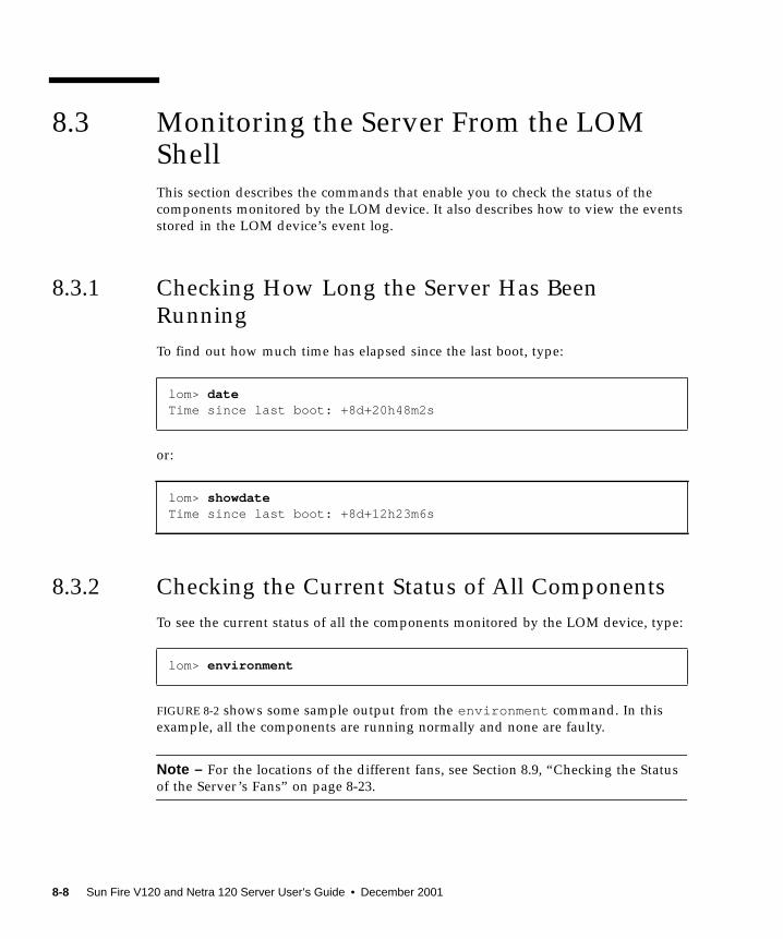
8.3 Monitoring the Server From the LOMShellThis section describes the commands that enable you to check the status of the
components monitored by the LOM device. It also describes how to view the events
stored in the LOM device’s event log.
8.3.1 Checking How Long the Server Has Been
Running
To find out how much time has elapsed since the last boot, type:
or:
8.3.2 Checking the Current Status of All Components
To see the current status of all the components monitored by the LOM device, type:
FIGURE 8-2 shows some sample output from the environment command. In this
example, all the components are running normally and none are faulty.
Note – For the locations of the different fans, see Section 8.9, “Checking the Status
of the Server’s Fans” on page 8-23.
lom> dateTime since last boot: +8d+20h48m2s
lom> showdateTime since last boot: +8d+12h23m6s
lom> environment
8-8 Sun Fire V120 and Netra 120 Server User’s Guide • December 2001
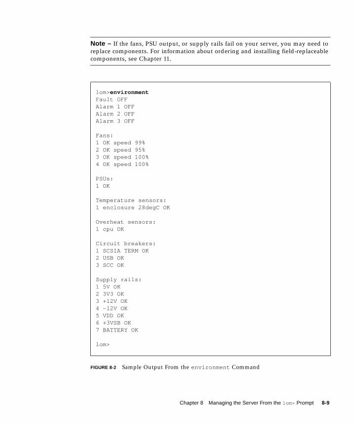
Note – If the fans, PSU output, or supply rails fail on your server, you may need to
replace components. For information about ordering and installing field-replaceable
components, see Chapter 11.
FIGURE 8-2 Sample Output From the environment Command
lom> environmentFault OFFAlarm 1 OFFAlarm 2 OFFAlarm 3 OFF
Fans:1 OK speed 99%2 OK speed 95%3 OK speed 100%4 OK speed 100%
PSUs:1 OK
Temperature sensors:1 enclosure 28degC OK
Overheat sensors:1 cpu OK
Circuit breakers:1 SCSIA TERM OK2 USB OK3 SCC OK
Supply rails:1 5V OK2 3V3 OK3 +12V OK4 -12V OK5 VDD OK6 +3VSB OK7 BATTERY OK
lom>
Chapter 8 Managing the Server From the lom> Prompt 8-9
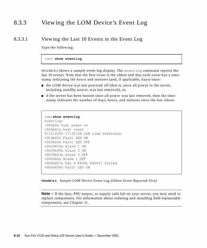
8.3.3 Viewing the LOM Device’s Event Log
8.3.3.1 Viewing the Last 10 Events in the Event Log
Type the following:
FIGURE 8-3 shows a sample event log display. The eventlog command reports the
last 10 events. Note that the first event is the oldest and that each event has a time-
stamp indicating the hours and minutes (and, if applicable, days) since:
■ the LOM device was last powered off (that is, since all power to the server,
including standby power, was last removed), or,
■ if the server has been booted since all power was last removed, then the time-
stamp indicates the number of days, hours, and minutes since the last reboot.
FIGURE 8-3 Sample LOM Device Event Log (Oldest Event Reported First)
Note – If the fans, PSU output, or supply rails fail on your server, you may need to
replace components. For information about ordering and installing field-replaceable
components, see Chapter 11.
lom> show eventlog
lom> show eventlogEventlog:+0h0m0s host power on+0h0m21s host reset9/15/2000 17:35:28 LOM time reference+0h3m20s Fault LED ON+0h3m24s Fault LED OFF+0h39m34s Alarm 1 ON+0h39m40s Alarm 3 ON+0h39m54s Alarm 3 OFF+0h40m0s Alarm 1 OFF+0h40m57s Fan 4 FATAL FAULT: failed+0h40m58s Fault LED ON
8-10 Sun Fire V120 and Netra 120 Server User’s Guide • December 2001

8.3.3.2 Viewing the Entire Event Log
● Type:
where x is the number of lines you want the screen to pause after displaying, and yis the severity level of the events you want to see. By default, the loghistorycommand displays all the events in the log and does not pause the display.
If you specify a severity level, you will see reports for the level you specify and
above. For example, if you specify level 2, you will see reports of level 2 and level 1
events. If you specify level 3, you will see reports of level 3, level 2, and level 1
events.
If you do not specify a level, you will see events for all levels.
For more information about severity levels, see Section 8.7, “Viewing the Event
Reports That the LOM Sends to syslogd” on page 8-20.
Each entry in the log includes the time of the event, the server’s host name, a unique
identifier for the event and a user-friendly text message describing the event.
Note – The LOM device’s Event Log is never cleared and can contain several
hundred entries. Events are stored from the very first time the server boots.
Eventually the buffer may become full, but when this happens the LOM device will
start again at the beginning of the buffer, over-writing the earliest events.
8.3.3.3 Viewing All Events From the First to the nth Event Logged
● Type:
where n is the number of events you want to see that have been logged since the first
event in the current log, x is the number of lines you want the screen to pause after
displaying, and y is the severity level of the events you want to see. By default, the
loghistory command does not pause the display.
lom> loghistory [pause x] [level y]
lom> loghistory index + n [pause x] [level y]
Chapter 8 Managing the Server From the lom> Prompt 8-11
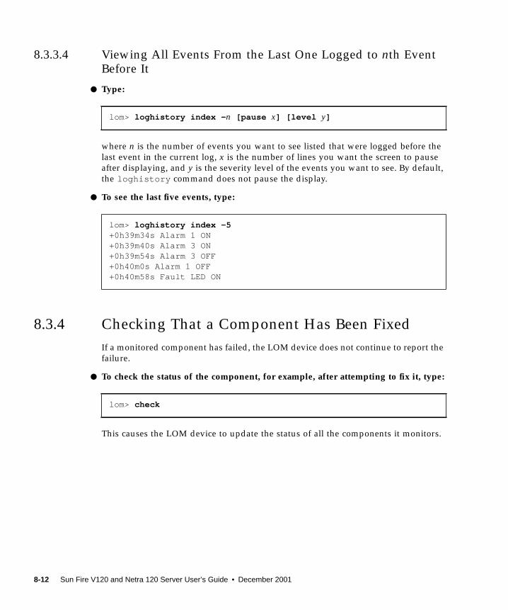
8.3.3.4 Viewing All Events From the Last One Logged to nth EventBefore It
● Type:
where n is the number of events you want to see listed that were logged before the
last event in the current log, x is the number of lines you want the screen to pause
after displaying, and y is the severity level of the events you want to see. By default,
the loghistory command does not pause the display.
● To see the last five events, type:
8.3.4 Checking That a Component Has Been Fixed
If a monitored component has failed, the LOM device does not continue to report the
failure.
● To check the status of the component, for example, after attempting to fix it, type:
This causes the LOM device to update the status of all the components it monitors.
lom> loghistory index - n [pause x] [level y]
lom> loghistory index -5+0h39m34s Alarm 1 ON+0h39m40s Alarm 3 ON+0h39m54s Alarm 3 OFF+0h40m0s Alarm 1 OFF+0h40m58s Fault LED ON
lom> check
8-12 Sun Fire V120 and Netra 120 Server User’s Guide • December 2001

8.4 Setting Up LOM Privileges for NamedUsersYou can specify up to four named users of the LOM device on a Sun Fire V120 or
Netra 120 server. By default no users are set up and therefore no user login prompt
appears when you use the LOM escape sequence.
However, if you set up one or more users, every time you use the LOM escape
sequence to display the lom> prompt you will be prompted for a user name and
password. Therefore, one of the user accounts you set up, must be for yourself.
Four levels of authorization are available for named users. By default all four levels
are open to them. However, if you specify any (using the lom> userpermcommand), only the level or levels that you specify will be available.
8.4.1 Permission Levels Available for LOM Users
The four levels of authorization are:
■ Console permission (c -level)With this level of permission a named user can exit from the lom> prompt to the
Solaris prompt (if the Serial A/LOM port is shared between the LOM and the
console).
■ User administration permission (u-level)With this level of permission a named user can add and delete users and alter
their permission levels.
■ Administration permission (a-level)With this level of permission a named user can change the LOM device’s
configuration variables (see Section 8.1, “Introduction to Lights-Out
Management” on page 8-2).
■ Reset permission (r -level)With this level of permission a named user can reset the server and power it on
and off using the LOM device.
For information about how to assign one or more of these levels of authorization to
a named user, see Section 8.4.7, “Specifying Permissions for a Named User” on
page 8-16.
Chapter 8 Managing the Server From the lom> Prompt 8-13

8.4.2 Creating a LOM User Account
● Type:
where the user name is up to eight characters long, begins with an alphabetic
character and contains at least one lower-case alphabetic character. You can use any
of the following characters in the user name:
■ Alphabetic
■ Numeric
■ Period (.)
■ Underscore (_)
■ Hyphen (-)
Note – You must have User Administration (a-level) authorization to add a user
(see Section 8.4.1, “Permission Levels Available for LOM Users” on page 8-13). If you
have not added any users, you have a-level and all other levels of authorization by
default.
8.4.3 Specifying the Password for a LOM User Account
● Type:
where the user name is the name of a LOM user account that already exists.
Note – You must have User Administration (u-level) authorization to set a
password for a user (see Section 8.4.1, “Permission Levels Available for LOM Users”
on page 8-13).
lom> useradd user name
lom> userpassword user name
8-14 Sun Fire V120 and Netra 120 Server User’s Guide • December 2001

8.4.4 Viewing Details of a LOM User Account
● Type:
where the user name is the name of an existing LOM user account.
Note – You must have User Administration (u-level) authorization to view the
details of a LOM user account (see Section 8.4.1, “Permission Levels Available for
LOM Users” on page 8-13).
8.4.5 Changing Your Own User Password
1. To change the password for the account you are currently logged into, type:
2. When prompted, specify the current password.
3. When prompted, specify the new password you want to use.
4. Specify the new password again to confirm it.
8.4.6 Deleting a LOM User Account
● Type:
where the user name is the name of an existing LOM user account.
Note – You must have User Administration (a-level) authorization to delete a user
account (see Section 8.4.1, “Permission Levels Available for LOM Users” on
page 8-13).
lom> usershow user name
lom> password
lom> userdel user name
Chapter 8 Managing the Server From the lom> Prompt 8-15
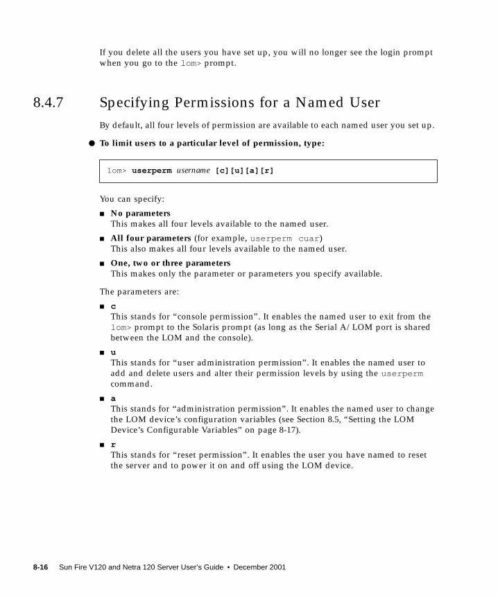
If you delete all the users you have set up, you will no longer see the login prompt
when you go to the lom> prompt.
8.4.7 Specifying Permissions for a Named User
By default, all four levels of permission are available to each named user you set up.
● To limit users to a particular level of permission, type:
You can specify:
■ No parametersThis makes all four levels available to the named user.
■ All four parameters (for example, userperm cuar )
This also makes all four levels available to the named user.
■ One, two or three parametersThis makes only the parameter or parameters you specify available.
The parameters are:
■ cThis stands for “console permission”. It enables the named user to exit from the
lom> prompt to the Solaris prompt (as long as the Serial A/LOM port is shared
between the LOM and the console).
■ uThis stands for “user administration permission”. It enables the named user to
add and delete users and alter their permission levels by using the userpermcommand.
■ aThis stands for “administration permission”. It enables the named user to change
the LOM device’s configuration variables (see Section 8.5, “Setting the LOM
Device’s Configurable Variables” on page 8-17).
■ rThis stands for “reset permission”. It enables the user you have named to reset
the server and to power it on and off using the LOM device.
lom> userperm username [c][u][a][r]
8-16 Sun Fire V120 and Netra 120 Server User’s Guide • December 2001

8.4.8 Quitting a LOM Named User Session
● Type:
This returns you to the LOM login prompt.
8.5 Setting the LOM Device’s ConfigurableVariablesThere are some variables that you can use as arguments to the set command in the
LOM shell. The set command duplicates the faulton , faultoff , alarmon and
alarmoff commands by taking them as arguments. It also takes the argument
event_reporting , which enables you to stop the LOM device from sending event
reports to the Serial A/LOM port.
Note – To execute the commands described in this section, a named user must have
a-level permission. For more information, see Section 8.4, “Setting Up LOM
Privileges for Named Users” on page 8-13.
8.5.1 Turning the Fault LED on
● To turn the Fault LED on by setting the faulton variable, type:
8.5.2 Turning the Fault LED off
● To turn the Fault LED off by setting the faultoff variable, type:
lom> logout
lom> set faulton
lom> set faultoff
Chapter 8 Managing the Server From the lom> Prompt 8-17
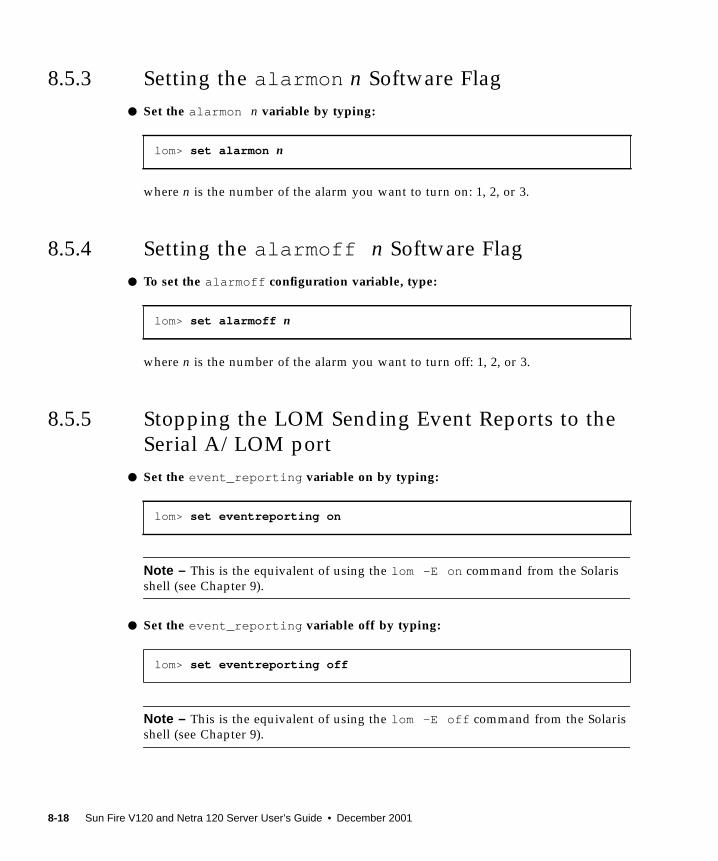
8.5.3 Setting the alarmon n Software Flag
● Set the alarmon n variable by typing:
where n is the number of the alarm you want to turn on: 1, 2, or 3.
8.5.4 Setting the alarmoff n Software Flag
● To set the alarmoff configuration variable, type:
where n is the number of the alarm you want to turn off: 1, 2, or 3.
8.5.5 Stopping the LOM Sending Event Reports to the
Serial A/LOM port
● Set the event_reporting variable on by typing:
Note – This is the equivalent of using the lom -E on command from the Solaris
shell (see Chapter 9).
● Set the event_reporting variable off by typing:
Note – This is the equivalent of using the lom -E off command from the Solaris
shell (see Chapter 9).
lom> set alarmon n
lom> set alarmoff n
lom> set eventreporting on
lom> set eventreporting off
8-18 Sun Fire V120 and Netra 120 Server User’s Guide • December 2001
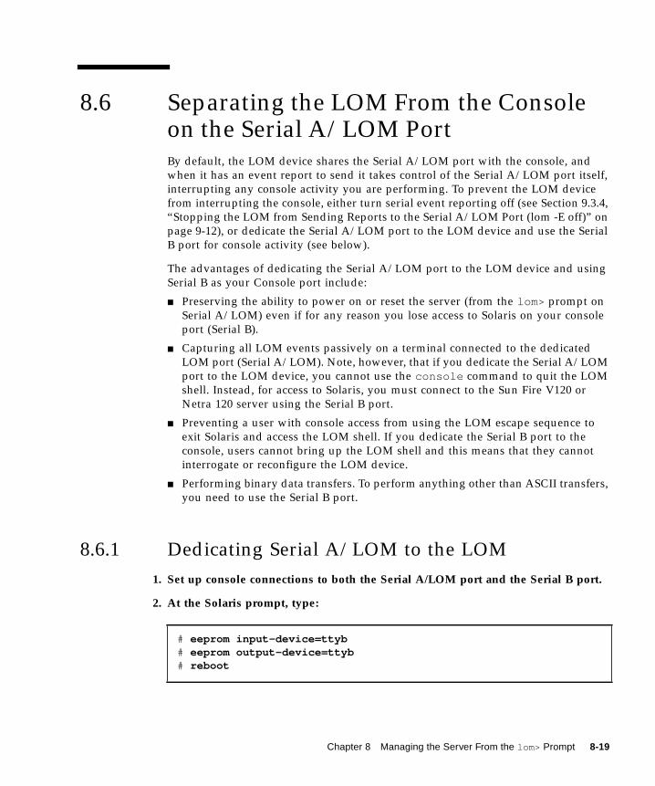
8.6 Separating the LOM From the Consoleon the Serial A/LOM PortBy default, the LOM device shares the Serial A/LOM port with the console, and
when it has an event report to send it takes control of the Serial A/LOM port itself,
interrupting any console activity you are performing. To prevent the LOM device
from interrupting the console, either turn serial event reporting off (see Section 9.3.4,
“Stopping the LOM from Sending Reports to the Serial A/LOM Port (lom -E off)” on
page 9-12), or dedicate the Serial A/LOM port to the LOM device and use the Serial
B port for console activity (see below).
The advantages of dedicating the Serial A/LOM port to the LOM device and using
Serial B as your Console port include:
■ Preserving the ability to power on or reset the server (from the lom> prompt on
Serial A/LOM) even if for any reason you lose access to Solaris on your console
port (Serial B).
■ Capturing all LOM events passively on a terminal connected to the dedicated
LOM port (Serial A/LOM). Note, however, that if you dedicate the Serial A/LOM
port to the LOM device, you cannot use the console command to quit the LOM
shell. Instead, for access to Solaris, you must connect to the Sun Fire V120 or
Netra 120 server using the Serial B port.
■ Preventing a user with console access from using the LOM escape sequence to
exit Solaris and access the LOM shell. If you dedicate the Serial B port to the
console, users cannot bring up the LOM shell and this means that they cannot
interrogate or reconfigure the LOM device.
■ Performing binary data transfers. To perform anything other than ASCII transfers,
you need to use the Serial B port.
8.6.1 Dedicating Serial A/LOM to the LOM
1. Set up console connections to both the Serial A/LOM port and the Serial B port.
2. At the Solaris prompt, type:
# eeprom input-device=ttyb# eeprom output-device=ttyb# reboot
Chapter 8 Managing the Server From the lom> Prompt 8-19

The Serial B port (ttyb) is now your console port. The Serial A/LOM port remains in
the control of the LOM device.
8.6.2 Sharing Serial A/LOM Between the LOM and the
Console
By default, the Serial A/LOM port is shared by the LOM device and the console.
Therefore, you only need to follow the instructions in this section if you have
configured the server by using the instructions in the previous section (Section 8.6.1,
“Dedicating Serial A/LOM to the LOM” on page 8-19) and you now want to share
the Serial A/LOM port between the LOM and the console.
To share the port between the LOM device and the console:
1. Set up console connections to both the Serial A/LOM port and the Serial B port.
2. At the Solaris prompt, type:
The Serial A/LOM port (ttya) is now shared between the LOM device and the
console.
8.7 Viewing the Event Reports That theLOM Sends to syslogdThe LOM device monitors the status of the fans, supply rails, temperature, and
power supply even when the server is powered down (the LOM device operates on
standby power). If it detects a fault, it turns on the Fault LED on the server’s front
and back panels and stores a report in an event log which resides in memory on the
LOM device. When Solaris is running, the LOM device also sends event reports to
syslogd . syslogd handles these in the way it has been configured to handle event
reports. This means that by default it sends them to the console and stores them in
the following file:
/var/adm/messages
# eeprom input-device=ttya# eeprom output-device=ttya# reboot
8-20 Sun Fire V120 and Netra 120 Server User’s Guide • December 2001

In this file the reports are displayed with a label identifying them as lom reports and
indicating their severity. The different levels of severity are, in descending order:
1. Fatal
These events might concern, for example, exceeded temperature thresholds or
supply rail failures. Fatal events may cause the server to shut itself down.
2. Warning
These events might concern fans turning too slowly, the Fault LED having been
turned on, or the System Configuration Card having been removed. They are not
events that cause the server to shut down, but they do require immediate attention.
3. Info
These events are most likely to inform you that some problem is now OK. For
example, if you re-insert the System Configuration Card, the LOM device will
generate an event to say that the System Configuration Card has been restored.
4. User
User level events concern the activity of named users whom you have authorized to
access the LOM device. For example, an event is generated when a user logs in or
out.
8.8 The LOM Shell Command ListThe commands you can execute from the lom> prompt are listed in TABLE 8-2.
TABLE 8-2 LOM Commands
Command Effect
alarmoff n Sets alarm n off.
(Where n is 1, 2, or 3.) These three alarms are software flags. They are
associated with no specific conditions but are available to be set by
your own processes.
alarmon n Sets alarm n on.
See the description for the alarmoff command.
break Takes the server down to the ok prompt.
bootmode Determines the behavior of the server during the boot process.
Chapter 8 Managing the Server From the lom> Prompt 8-21
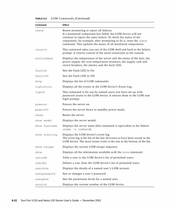
check Resets monitoring to report all failures.
If a monitored component has failed, the LOM device will not
continue to report the same failure. To check the status of the
component, for example, after attempting to fix it, issue the checkcommand. This updates the status of all monitored components.
console This command takes you out of the LOM shell and back to the Solaris
prompt. It returns control of the serial connection to the console.
environment Displays the temperature of the server and the status of the fans, the
power supply, the over-temperature monitors, the supply rails and
circuit breakers, the alarms, and the fault LED.
faulton Sets the Fault LED to On.
faultoff Sets the Fault LED to Off.
help Displays the list of LOM commands.
loghistory Displays all the events in the LOM device’s Event Log.
logout This command is for use by named users you have set up with
password access to the LOM device. It returns them to the LOM user
login prompt.
poweron Powers the server on.
poweroff Powers the server down to standby power mode.
reset Resets the server.
show model Displays the server model.
show hostname Displays the server name (this command is equivalent to the Solaris
uname -n command).
show eventlog Displays the LOM device’s event log.
The event log is the list of the last 10 events to have been stored in the
LOM device. The most recent event is the one at the bottom of the list.
show escape Displays the current LOM escape sequence.
show Displays all the information available with the show command.
useradd Adds a user to the LOM device’s list of permitted users.
userdel Deletes a user from the LOM device’s list of permitted users.
usershow Displays the details of a named user’s LOM account.
userpassword Sets or changes a user’s password.
userperm Sets the permission levels for a named user.
version Displays the version number of the LOM device.
TABLE 8-2 LOM Commands (Continued)
Command Effect
8-22 Sun Fire V120 and Netra 120 Server User’s Guide • December 2001

8.9 Checking the Status of the Server’s FansEvent reports about the fans inside the server include the number of the fan to
which they relate. Fans 1 and 2 expel hot air from the server; Fan 3 cools the CPU.
Fan 4 is the power supply fan; if this fan fails, you must replace the PSU.
FIGURE 8-4 Locations of Fans 1, 2, 3, and 4
● To check the status of the fans, type:
lom> environment
Fan 1
Fan 2
Fan 1
Fan 4
Fan 3
Chapter 8 Managing the Server From the lom> Prompt 8-23

8-24 Sun Fire V120 and Netra 120 Server User’s Guide • December 2001
CHAPTER 9
Managing the Server From theSolaris Prompt
This chapter tells you how to use the LOM-specific commands available in the
Solaris operating environment for monitoring and managing a Sun Fire V120 or
Netra 120 server.
For an introduction to the LOM device and a description of an alternative user
interface to it, see Chapter 8.
The chapter contains the following sections:
■ Section 9.1, “Monitoring the System From Solaris” on page 9-2
■ Section 9.2, “Configuring Automatic Server Restart (ASR)” on page 9-8
■ Section 9.3, “Other LOM Tasks You Can Perform From Solaris” on page 9-11
Note – For information about how to configure the LOM device driver, see
Appendix C.
Note – The Sun Fire V120 and Netra 120 servers are supplied with the Solaris
operating environment installed and with the supplementary Lights-Out
Management (LOM) software described in this chapter and Chapter 8 also installed.
This software enables you to manage the server locally or remotely. If you ever need
to re-install Solaris and you want to use the Lights-Out Management facilities, you
must also re-install the Lights-Out Management software from the CD entitled
Software Supplement for the Solaris Operating Environment. This CD is included with
the Solaris media kit. For the location of the LOM packages on the CD, refer to the
Solaris Hardware Platform Guide for the release of Solaris that you are using.
9-1

9.1 Monitoring the System From SolarisTo use the Lights-Out Management (LOM) facilities either remotely or locally, you
need a terminal connection to the Serial A/LOM port on the server (see Chapter 6).
There are two ways of interrogating the LOM device or of sending it commands to
perform.
■ One is by executing LOM commands from the lom> shell prompt. For
information about how to do this, see Chapter 8.
■ The other is by executing LOM-specific Solaris commands from the Solaris
prompt. These commands are described in this chapter.
The Solaris commands described in this section are all available from the main
Solaris # prompt. They run a utility called /usr/sbin/lom .
Where appropriate, the command lines given in this section are accompanied by
typical output from the commands.
9.1.1 Viewing Online LOM Documentation
● To view the manual pages for the LOM utility, type:
9.1.2 Checking the Power Supply Unit (lom -p )
● To check that the input lines and the output line for the power supply unit areworking normally, type:
# man lom
# lom -pPSUs:1 OK
#
9-2 Sun Fire V120 and Netra 120 Server User’s Guide • December 2001

Note – If there are any failures of the PSU that affect more than just the input or
output lines, Solaris will not run. However, if standby power is present, you can still
use the LOM shell commands described in Chapter 8.
9.1.3 Checking the Fans (lom -f )
● To check the fans, type:
For the locations of each fan, see Section 8.9, “Checking the Status of the Server’s
Fans” on page 8-23. If you need to replace a fan, contact your local Sun sales
representative and quote the part number of the component you need. For
information, see Section 11.2, “Field Replaceable Units” on page 11-4.
9.1.4 Checking the Supply Rail Voltages and Internal
Circuit Breakers (lom -v )
The supply rails are the server’s internal power lines. If the status of any of these is
faulty , contact your local Sun sales representative. It means that you have either a
faulty system board or a faulty PSU. For information about ordering and installing
replacements of these components, see Chapter 11.
The -v option also displays the status of the Sun Fire V120 or Netra 120 server’s
internal circuit breakers. For any that have been tripped, the status will read faulty .
The system contains three circuit breakers: one for the SCSI connector, one for the
USB ports, and one for the System Configuration Card reader. If there is a problem
with the circuit breakers or the SCSI or USB port circuit breakers, remove the device
connected to the relevant port. When you do this, the circuit breakers will
automatically recover themselves. If there is a problem with the circuit breaker for
the System Configuration Card, it means that you do not have a valid System
Configuration Card inserted.
# lom -fFans:1 OK speed 99%2 OK speed 95%3 OK speed 100%4 OK speed 100%
#
Chapter 9 Managing the Server From the Solaris Prompt 9-3
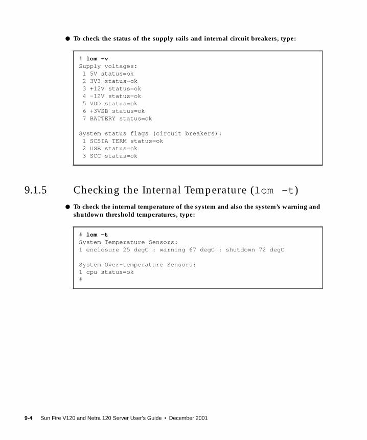
● To check the status of the supply rails and internal circuit breakers, type:
9.1.5 Checking the Internal Temperature (lom -t )
● To check the internal temperature of the system and also the system’s warning andshutdown threshold temperatures, type:
# lom -vSupply voltages: 1 5V status=ok 2 3V3 status=ok 3 +12V status=ok 4 -12V status=ok 5 VDD status=ok 6 +3VSB status=ok 7 BATTERY status=ok
System status flags (circuit breakers): 1 SCSIA TERM status=ok 2 USB status=ok 3 SCC status=ok
# lom -tSystem Temperature Sensors:1 enclosure 25 degC : warning 67 degC : shutdown 72 degC
System Over-temperature Sensors:1 cpu status=ok#
9-4 Sun Fire V120 and Netra 120 Server User’s Guide • December 2001
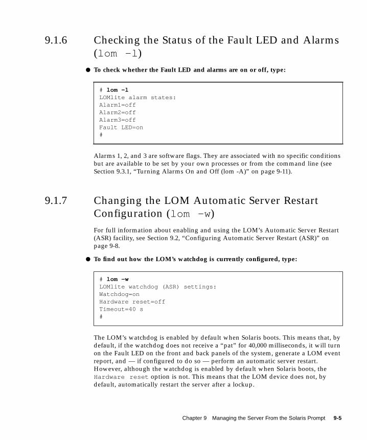
9.1.6 Checking the Status of the Fault LED and Alarms
(lom -l )
● To check whether the Fault LED and alarms are on or off, type:
Alarms 1, 2, and 3 are software flags. They are associated with no specific conditions
but are available to be set by your own processes or from the command line (see
Section 9.3.1, “Turning Alarms On and Off (lom -A)” on page 9-11).
9.1.7 Changing the LOM Automatic Server Restart
Configuration (lom -w )
For full information about enabling and using the LOM’s Automatic Server Restart
(ASR) facility, see Section 9.2, “Configuring Automatic Server Restart (ASR)” on
page 9-8.
● To find out how the LOM’s watchdog is currently configured, type:
The LOM’s watchdog is enabled by default when Solaris boots. This means that, by
default, if the watchdog does not receive a “pat” for 40,000 milliseconds, it will turn
on the Fault LED on the front and back panels of the system, generate a LOM event
report, and — if configured to do so — perform an automatic server restart.
However, although the watchdog is enabled by default when Solaris boots, the
Hardware reset option is not. This means that the LOM device does not, by
default, automatically restart the server after a lockup.
# lom -lLOMlite alarm states:Alarm1=offAlarm2=offAlarm3=offFault LED=on#
# lom -wLOMlite watchdog (ASR) settings:Watchdog=onHardware reset=offTimeout=40 s#
Chapter 9 Managing the Server From the Solaris Prompt 9-5

● To configure the LOM device to perform an automatic server restart (ASR) after alockup, you must enable the Hardware reset option as well as the Watchdogoption. For information about how to do this, see Section 9.2, “ConfiguringAutomatic Server Restart (ASR)” on page 9-8.
9.1.8 Viewing the Configuration of the LOM Device
(lom -c )
● To view the settings of all the configurable variables for the LOM device, type:
9.1.9 Viewing All Component Status Data With the
LOM Device’s Configuration Data (lom -a )
● To view all the status data stored by the LOM device plus the details of thedevice’s own configuration, type:
# lom -cLOMlite configuration settings:serial escape character=#serial event reporting=defaultEvent reporting level=fatal, warning & informationSerial security=enabledDisable watchdog on break=disabledAutomatic return to console=disabledalarm3 mode=watchdogfirmware version=3.0firmware checksum=2983product revision=0.0product ID=120#
# lom -a
9-6 Sun Fire V120 and Netra 120 Server User’s Guide • December 2001
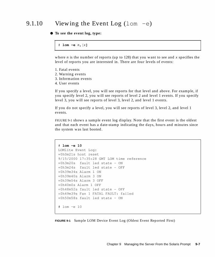
9.1.10 Viewing the Event Log (lom -e )
● To see the event log, type:
where n is the number of reports (up to 128) that you want to see and x specifies the
level of reports you are interested in. There are four levels of events:
1. Fatal events
2. Warning events
3. Information events
4. User events
If you specify a level, you will see reports for that level and above. For example, if
you specify level 2, you will see reports of level 2 and level 1 events. If you specify
level 3, you will see reports of level 3, level 2, and level 1 events.
If you do not specify a level, you will see reports of level 3, level 2, and level 1
events.
FIGURE 9-1 shows a sample event log display. Note that the first event is the oldest
and that each event has a date-stamp indicating the days, hours and minutes since
the system was last booted.
FIGURE 9-1 Sample LOM Device Event Log (Oldest Event Reported First)
# lom -e n, [ x]
# lom -e 10LOMlite Event Log:+0h0m21s host reset9/15/2000 17:35:28 GMT LOM time reference+0h3m20s fault led state - ON+0h3m24s fault led state - OFF+0h39m34s Alarm 1 ON+0h39m40s Alarm 3 ON+0h39m54s Alarm 3 OFF+0h40m0s Alarm 1 OFF+0h48m52s fault led state - OFF+0h49m39s Fan 1 FATAL FAULT: failed+0h50m58s fault led state - ON
# lom -e 10
Chapter 9 Managing the Server From the Solaris Prompt 9-7
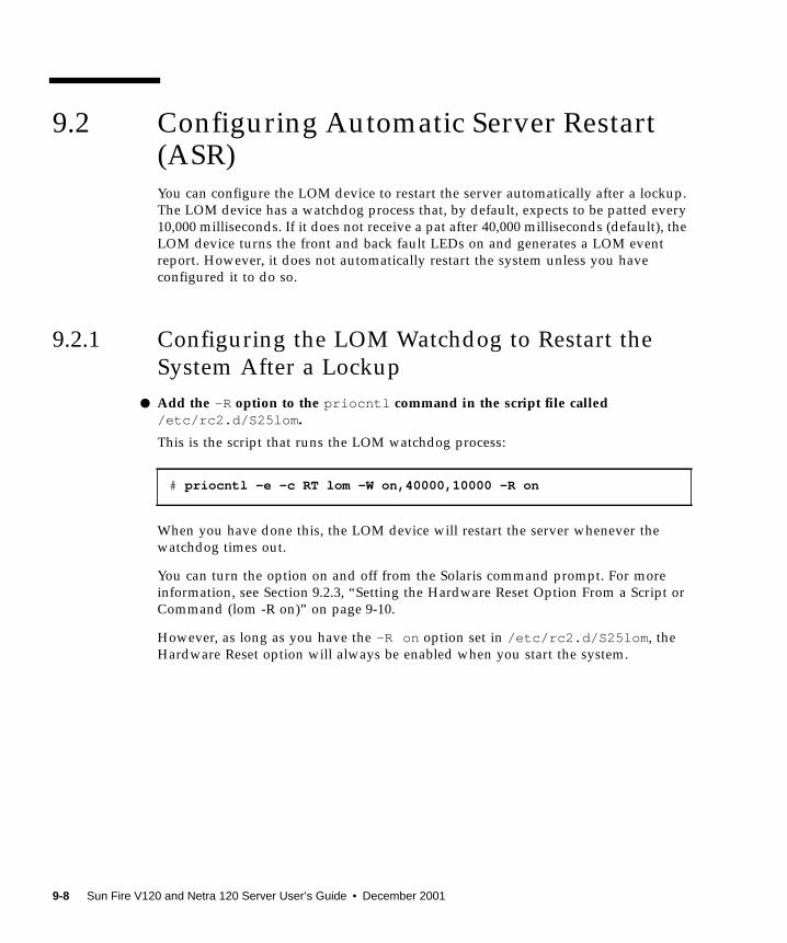
9.2 Configuring Automatic Server Restart(ASR)You can configure the LOM device to restart the server automatically after a lockup.
The LOM device has a watchdog process that, by default, expects to be patted every
10,000 milliseconds. If it does not receive a pat after 40,000 milliseconds (default), the
LOM device turns the front and back fault LEDs on and generates a LOM event
report. However, it does not automatically restart the system unless you have
configured it to do so.
9.2.1 Configuring the LOM Watchdog to Restart the
System After a Lockup
● Add the -R option to the priocntl command in the script file called/etc/rc2.d/S25lom .
This is the script that runs the LOM watchdog process:
When you have done this, the LOM device will restart the server whenever the
watchdog times out.
You can turn the option on and off from the Solaris command prompt. For more
information, see Section 9.2.3, “Setting the Hardware Reset Option From a Script or
Command (lom -R on)” on page 9-10.
However, as long as you have the -R on option set in /etc/rc2.d/S25lom , the
Hardware Reset option will always be enabled when you start the system.
# priocntl -e -c RT lom -W on,40000,10000 -R on
9-8 Sun Fire V120 and Netra 120 Server User’s Guide • December 2001

9.2.2 Enabling the LOM Watchdog Process From Your
Own Script or Command (lom -W on )
Note – You do not normally need to do this. If you want to configure the LOM
device to perform an automatic server restart after a lockup, see Section 9.2.1,
“Configuring the LOM Watchdog to Restart the System After a Lockup” on page 9-8.
Only use the lom -W on option on the command line or in another script file if for
some reason you have removed the /etc/rc2.d/S25lom script.
The LOM device’s watchdog process is enabled by default and, if you type
lom -W on while this watchdog process is already running, the command will have
no effect. You can only run this command if you have removed the
/etc/rc2.d/S25lom script file or you have turned the watchdog off manually by
using the lom -W off command.
The default priocntl command is as follows:
priocntl -e -c RT lom -W on,40000,10000
The number 40,000 on this command line indicates the watchdog’s timeout period in
milliseconds; you can specify a different number. The number 10,000 indicates its pat
interval in milliseconds; again, you can specify a different number.
Note – Do not specify a watchdog timeout period of less than 5,000 milliseconds. If
you do, you might find that the watchdog times out frequently even though the
server has not locked up. And this could cause your server to panic unnecessarily.
If the watchdog process times out (in other words, if it does not receive its expected
pat), the LOM device will turn on the server’s front and back Fault LEDs and
generate a LOM event report. However, it will not automatically reset the system. To
make it reset the system, you must use the -R option (see Section 9.2.3, “Setting the
Hardware Reset Option From a Script or Command (lom -R on)” on page 9-10.)
● If you have no LOM watchdog process running already and you want the processto run, type the following, or add it to another script file:
● If you want the LOM device to perform an automatic server restart after a lockup,you must include the -R on option in the command, as follows:
# lom -W on,40000,10000
# lom -W on,40000,10000 -R on
Chapter 9 Managing the Server From the Solaris Prompt 9-9

Note – Unless you include the lom -W on and -R on options in a script file, you
will need to execute the lom command every time you reboot the system. (That is, if
you want to use the automatic server restart facility.) Otherwise the watchdog will
not run, and the server will not reset after a lockup.
9.2.3 Setting the Hardware Reset Option From a
Script or Command (lom -R on )
To make the LOM device’s watchdog process trigger an automatic server restart
(ASR) after a lockup, add the -R on option to the command in your
/etc/rc2.d/S25lom script file. This is the script that runs the watchdog. For full
instructions about how to do this, see Section 9.2.1, “Configuring the LOM
Watchdog to Restart the System After a Lockup” on page 9-8.
● However, if for any reason you are not using the script file provided with yoursystem (/etc/rc2.d/S25lom ) but have instead enabled the watchdog from thecommand line or from another script file, you can turn the Hardware resetoption on by typing the following at the command line:
● To turn the Hardware reset option off from the command line,type:
# lom -R on
# lom -R off
9-10 Sun Fire V120 and Netra 120 Server User’s Guide • December 2001
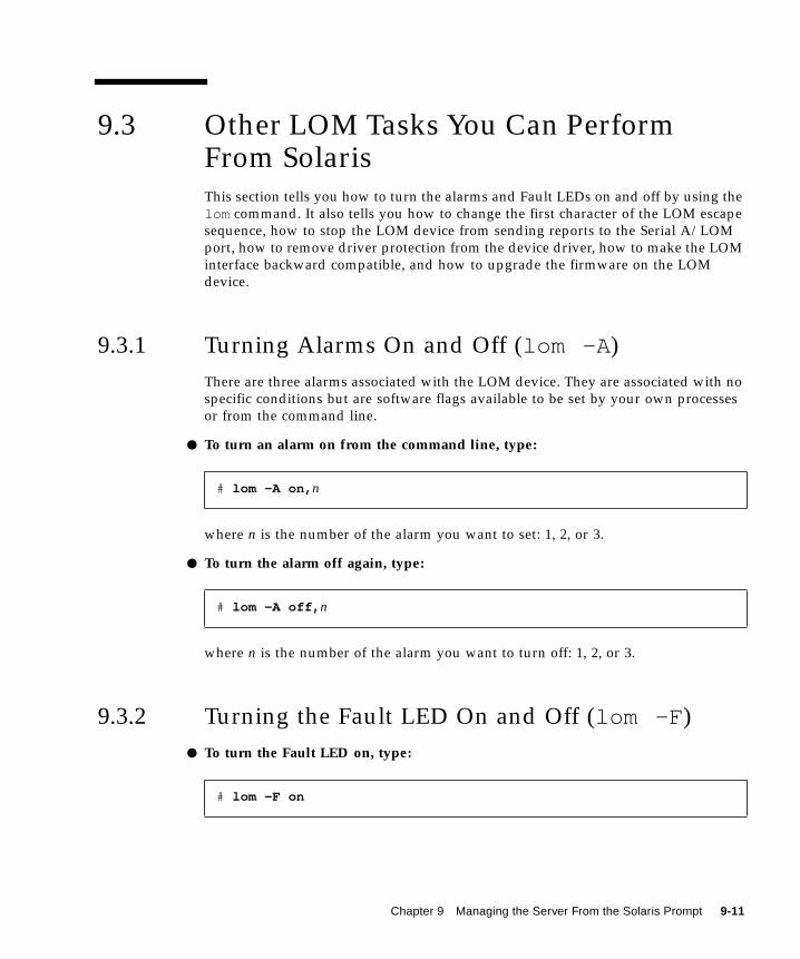
9.3 Other LOM Tasks You Can PerformFrom SolarisThis section tells you how to turn the alarms and Fault LEDs on and off by using the
lom command. It also tells you how to change the first character of the LOM escape
sequence, how to stop the LOM device from sending reports to the Serial A/LOM
port, how to remove driver protection from the device driver, how to make the LOM
interface backward compatible, and how to upgrade the firmware on the LOM
device.
9.3.1 Turning Alarms On and Off (lom -A )
There are three alarms associated with the LOM device. They are associated with no
specific conditions but are software flags available to be set by your own processes
or from the command line.
● To turn an alarm on from the command line, type:
where n is the number of the alarm you want to set: 1, 2, or 3.
● To turn the alarm off again, type:
where n is the number of the alarm you want to turn off: 1, 2, or 3.
9.3.2 Turning the Fault LED On and Off (lom -F )
● To turn the Fault LED on, type:
# lom -A on, n
# lom -A off, n
# lom -F on
Chapter 9 Managing the Server From the Solaris Prompt 9-11
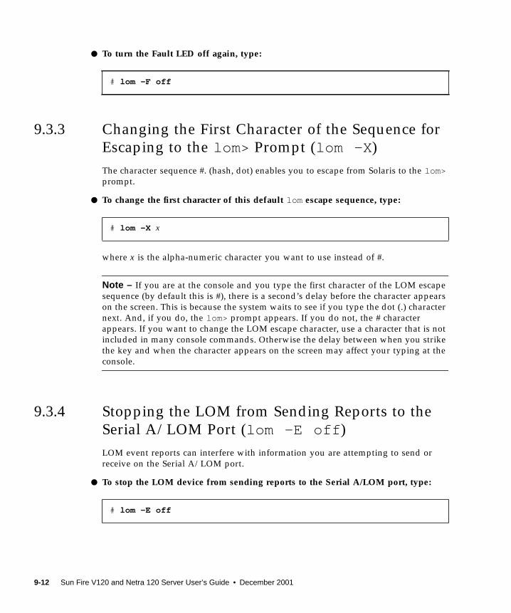
● To turn the Fault LED off again, type:
9.3.3 Changing the First Character of the Sequence for
Escaping to the lom> Prompt (lom -X )
The character sequence #. (hash, dot) enables you to escape from Solaris to the lom>prompt.
● To change the first character of this default lom escape sequence, type:
where x is the alpha-numeric character you want to use instead of #.
Note – If you are at the console and you type the first character of the LOM escape
sequence (by default this is #), there is a second’s delay before the character appears
on the screen. This is because the system waits to see if you type the dot (.) character
next. And, if you do, the lom> prompt appears. If you do not, the # character
appears. If you want to change the LOM escape character, use a character that is not
included in many console commands. Otherwise the delay between when you strike
the key and when the character appears on the screen may affect your typing at the
console.
9.3.4 Stopping the LOM from Sending Reports to the
Serial A/LOM Port (lom -E off )
LOM event reports can interfere with information you are attempting to send or
receive on the Serial A/LOM port.
● To stop the LOM device from sending reports to the Serial A/LOM port, type:
# lom -F off
# lom -X x
# lom -E off
9-12 Sun Fire V120 and Netra 120 Server User’s Guide • December 2001
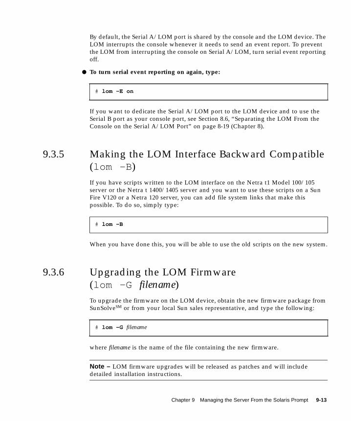
By default, the Serial A/LOM port is shared by the console and the LOM device. The
LOM interrupts the console whenever it needs to send an event report. To prevent
the LOM from interrupting the console on Serial A/LOM, turn serial event reporting
off.
● To turn serial event reporting on again, type:
If you want to dedicate the Serial A/LOM port to the LOM device and to use the
Serial B port as your console port, see Section 8.6, “Separating the LOM From the
Console on the Serial A/LOM Port” on page 8-19 (Chapter 8).
9.3.5 Making the LOM Interface Backward Compatible
(lom -B )
If you have scripts written to the LOM interface on the Netra t1 Model 100/105
server or the Netra t 1400/1405 server and you want to use these scripts on a Sun
Fire V120 or a Netra 120 server, you can add file system links that make this
possible. To do so, simply type:
When you have done this, you will be able to use the old scripts on the new system.
9.3.6 Upgrading the LOM Firmware
(lom -G filename)
To upgrade the firmware on the LOM device, obtain the new firmware package from
SunSolveSM or from your local Sun sales representative, and type the following:
where filename is the name of the file containing the new firmware.
Note – LOM firmware upgrades will be released as patches and will include
detailed installation instructions.
# lom -E on
# lom -B
# lom -G filename
Chapter 9 Managing the Server From the Solaris Prompt 9-13

9-14 Sun Fire V120 and Netra 120 Server User’s Guide • December 2001
PART III Troubleshooting and Maintenance


CHAPTER 10
Troubleshooting
This chapter provides introductory information on the diagnostics tools available for
the Sun Fire V120 and Netra 120 servers. It also lists some problems that you might
encounter when setting up or using a Sun Fire V120 or Netra 120 server and tells
you how to solve them. Finally, the chapter explains how to interpret the LEDs on
the servers’ front and back panels.
The chapter contains the following sections:
■ Section 10.1, “Introduction to the POST, obdiag, and SunVTS Diagnostic Tools” on
page 10-2
■ Section 10.2, “Additional Diagnostic Tests for Specific Devices” on page 10-8
■ Section 10.3, “Solutions to Problems You Might Encounter” on page 10-10
■ Section 10.4, “Interpreting the Front and Back Panel LEDs” on page 10-12
10-1

10.1 Introduction to the POST, obdiag , andSunVTS Diagnostic ToolsThe following diagnostic tools are available for the Sun Fire V120 and Netra 120
servers:
■ Power On Self Test (POST) Diagnostics
■ OpenBoot Diagnostics (obdiag)
■ SunVTS
If you need to contact Sun to report a problem with your system, it will help the
engineers to resolve the problem if you can provide relevant diagnostic information
from these tools.
10.1.1 Using POST Diagnostics
To view Power On Self Test (POST) diagnostic and error messages you need to have
a serial connection set up to the server. For more information, see “Setting Up Serial
Connections” on page 6-4.
If your system has the OpenBoot PROM (OBP) variable diag-switch? set to true ,
then POST diagnostics will run automatically when you power on the server.
However, the default setting for diag-switch? is false .
To start POST diagnostics, at the ok prompt, do the following:
1. Type:
2. Type:
where value is either min or max (depending on the quantity of diagnostic
information you want to see).
3. Type:
ok setenv diag-switch? true
ok setenv diag-level value
ok reset-all
10-2 Sun Fire V120 and Netra 120 Server User’s Guide • December 2001

The system will now run POST diagnostics and display status and error messages in
your console window. If POST detects an error, it displays an error message
describing the failure. A sample error message is shown below:
4. When you have finished running POST, restore the value of diag-switch? tofalse by typing the following (this minimizes the booting time):
10.1.2 Using OpenBoot Diagnostics (obdiag )
To run OpenBoot Diagnostics, do the following:
1. Type:
2. Type:
This command displays the OpenBoot Diagnostics menu.
Power On Self Test Failed. Cause: DIMM U0702 or System Board
ok setenv diag-switch? false
ok setenv diag-switch? trueok setenv auto-boot? falseok reset-all
ok obdiag
FIGURE 10-1 Sample obdiag Menu
obdiag
1 SUNW,lomh@14,2000004 i2c-nvram@0,a07 network@c,110 scsi@8,113 usb@5,3
2 ebus@c5 ide@d8 pmu@311 serial@0,2e814 usb@c,3
3 flashprom@10,06 network@5,19 scsi@812 serial@0,3f8
Commands: test test-all except help what printenvs setenv versionsexit
Chapter 10 Troubleshooting 10-3

The tests are described in TABLE 10-1. Note the number that corresponds to the test
you want to perform, and use it with the test command. For example, to test the
primary Ethernet port, type:
3. When you have finished testing, exit OpenBoot Diagnostics and restore the valueof auto-boot? to true.
To do this, type:
The function of each test is shown below.
obdiag> test 7Hit the spacebar to interrupt testingTesting /pci@1f,0/ethernet@c ...........................passed
Hit any key to return to the main menu.
obdiag> exitok setenv auto-boot? trueok auto-boot? trueok boot
TABLE 10-1 Open Boot Diagnostics Tests
Test number Name Description
1 SUNW,lomh@14,200000 tests the LOM device
2 ebus@c tests the ebus interface
3 flashprom@10,0 tests the flashprom device
4 i2c-nvram@0,a0 tests the System Configuration Card
5 ide@d tests the ide interface (to the CD-ROM or
DVD drive)
6 network@5,1 tests the net1 Ethernet port
7 network@c,1 tests the net0 Ethernet port
8 pmu@3 tests the circuitry on the main CPU board
9 scsi@8 tests the internal SCSI interface
10 scsi@8,1 tests the external SCSI interface
11 serial@0,2e8 tests the serial B port (ttyb)
10-4 Sun Fire V120 and Netra 120 Server User’s Guide • December 2001
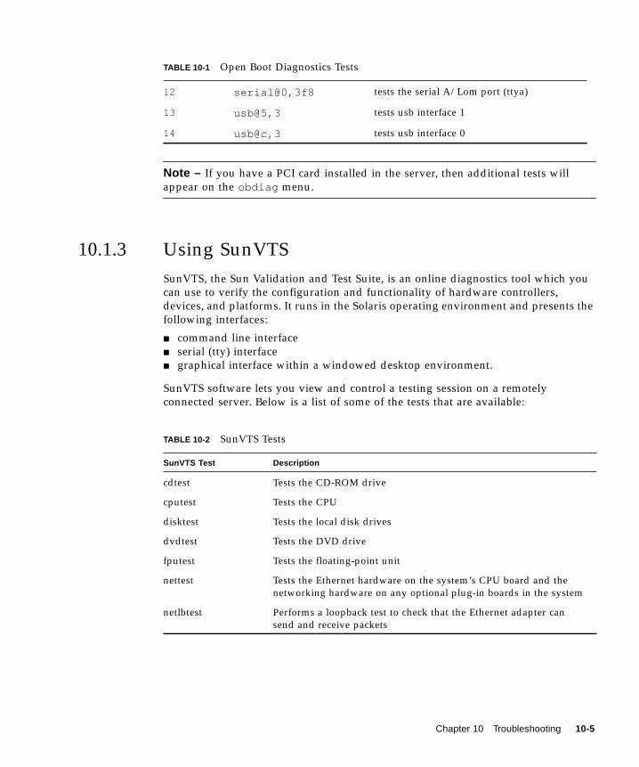
Note – If you have a PCI card installed in the server, then additional tests will
appear on the obdiag menu.
10.1.3 Using SunVTS
SunVTS, the Sun Validation and Test Suite, is an online diagnostics tool which you
can use to verify the configuration and functionality of hardware controllers,
devices, and platforms. It runs in the Solaris operating environment and presents the
following interfaces:
■ command line interface
■ serial (tty) interface
■ graphical interface within a windowed desktop environment.
SunVTS software lets you view and control a testing session on a remotely
connected server. Below is a list of some of the tests that are available:
12 serial@0,3f8 tests the serial A/Lom port (ttya)
13 usb@5,3 tests usb interface 1
14 usb@c,3 tests usb interface 0
TABLE 10-2 SunVTS Tests
SunVTS Test Description
cdtest Tests the CD-ROM drive
cputest Tests the CPU
disktest Tests the local disk drives
dvdtest Tests the DVD drive
fputest Tests the floating-point unit
nettest Tests the Ethernet hardware on the system’s CPU board and the
networking hardware on any optional plug-in boards in the system
netlbtest Performs a loopback test to check that the Ethernet adapter can
send and receive packets
TABLE 10-1 Open Boot Diagnostics Tests
Chapter 10 Troubleshooting 10-5
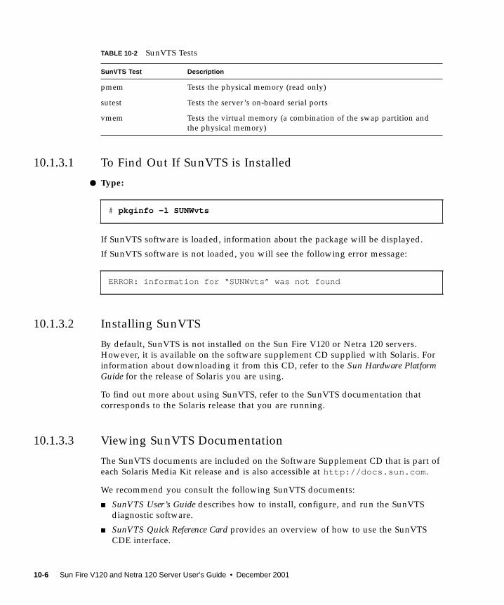
10.1.3.1 To Find Out If SunVTS is Installed
● Type:
If SunVTS software is loaded, information about the package will be displayed.
If SunVTS software is not loaded, you will see the following error message:
10.1.3.2 Installing SunVTS
By default, SunVTS is not installed on the Sun Fire V120 or Netra 120 servers.
However, it is available on the software supplement CD supplied with Solaris. For
information about downloading it from this CD, refer to the Sun Hardware PlatformGuide for the release of Solaris you are using.
To find out more about using SunVTS, refer to the SunVTS documentation that
corresponds to the Solaris release that you are running.
10.1.3.3 Viewing SunVTS Documentation
The SunVTS documents are included on the Software Supplement CD that is part of
each Solaris Media Kit release and is also accessible at http://docs.sun.com .
We recommend you consult the following SunVTS documents:
■ SunVTS User’s Guide describes how to install, configure, and run the SunVTS
diagnostic software.
■ SunVTS Quick Reference Card provides an overview of how to use the SunVTS
CDE interface.
pmem Tests the physical memory (read only)
sutest Tests the server’s on-board serial ports
vmem Tests the virtual memory (a combination of the swap partition and
the physical memory)
# pkginfo -l SUNWvts
ERROR: information for “SUNWvts” was not found
TABLE 10-2 SunVTS Tests
SunVTS Test Description
10-6 Sun Fire V120 and Netra 120 Server User’s Guide • December 2001
■ SunVTS Test Reference Manual provides details about each individual SunVTS test.
10.1.3.4 Using the SunVTS Graphical User Interface
To test the Sun Fire V120 or Netra 120 server by running a SunVTS session from a
workstation using the SunVTS graphical user interface, follow the procedure below.
1. Use the xhost command to give the remote server access to the local display.Type:
2. Remotely log in to the server as superuser or root.
3. Type:
where local_hostname is the name of the workstation you are using.
Note – The directory /opt/SUNWvts/bin is the default directory for SunVTS
software. If you have the software installed in a different directory, use that path
instead.
When you start SunVTS software, the SunVTS kernel probes the test system devices
and displays the results on the Test Selection panel. There is an associated SunVTS
test for each hardware device on your system.
You can fine-tune your testing session by selecting the appropriate check boxes for
each of the tests you want to run.
# /usr/openwin/bin/xhost + remote_hostname
# cd /opt/SUNWvts/bin# ./sunvts -display local_hostname:0
Chapter 10 Troubleshooting 10-7

10.2 Additional Diagnostic Tests for SpecificDevices
10.2.1 Using the probe-scsi Command To Confirm
That Hard Disk Drives Are Active
The probe-scsi command transmits an inquiry to SCSI devices connected to the
system’s internal SCSI interface. If a SCSI device is connected and active, the
command displays the unit number, device type, and manufacturer name for that
device.
The probe-scsi-all command transmits an inquiry to all SCSI devices connected
to both the system’s internal and its external SCSI interfaces. FIGURE 10-3 shows
sample output from a Sun Fire V120 with no externally connected SCSI devices but
containing two 36 GB Hard Disk Drives, both of them active.
FIGURE 10-2 probe-scsi Output Message
ok probe-scsi
Target 0
Unit 0 Disk SEAGATE ST336605LSUN36G 4207
Target 1
Unit 0 Disk SEAGATE ST336605LSUN36G 0136
FIGURE 10-3 probe-scsi-all Output Message
ok probe-scsi-all
/pci@1f,0/pci@1/scsi@8,1
/pci@1f,0/pci@1/scsi@8
Target 0
Unit 0 Disk SEAGATE ST336605LSUN36G 4207
Target 1
Unit 0 Disk SEAGATE ST336605LSUN36G 0136
10-8 Sun Fire V120 and Netra 120 Server User’s Guide • December 2001

10.2.2 Using the probe-ide Command To Confirm That
the DVD or CD-ROM Drive is Connected
The probe-ide command transmits an inquiry command to internal and external
IDE devices connected to the system’s on-board IDE interface. The following sample
output reports a DVD drive installed (as Device 0) and active in a Sun Fire V120
server.
10.2.3 Using the watch-net and watch-net-allCommands To Check the Network Connections
The watch-net diagnostics test monitors Ethernet packets on the primary network
interface. The watch-net-all diagnostics test monitors Ethernet packets on the
primary network interface and on any additional network interfaces connected to
the system board. Good packets received by the system are indicated by a period (.).
Errors such as the framing error and the cyclic redundancy check (CRC) error are
indicated with an X and an associated error description.
FIGURE 10-4 probe-ide Output Message
ok probe-ide
Device 0 ( Primary Master )
Removable ATAPI Model: DV-28E-B
Device 1 ( Primary Slave )
Not Present
Device 2 ( Secondary Master )
Not Present
Device 3 ( Secondary Slave )
Not Present
Chapter 10 Troubleshooting 10-9
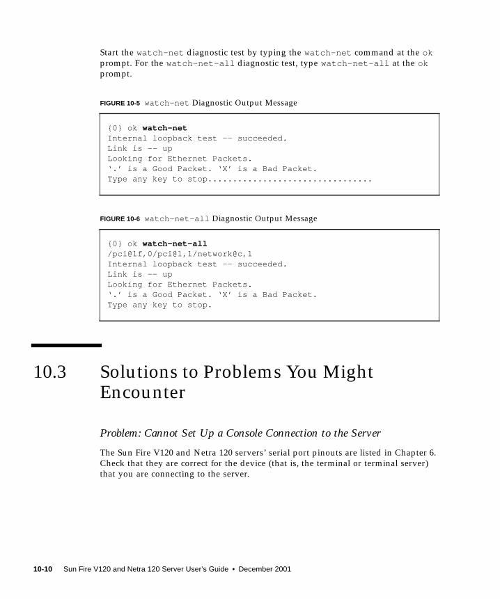
Start the watch-net diagnostic test by typing the watch-net command at the okprompt. For the watch-net-all diagnostic test, type watch-net-all at the okprompt.
10.3 Solutions to Problems You MightEncounter
Problem: Cannot Set Up a Console Connection to the Server
The Sun Fire V120 and Netra 120 servers’ serial port pinouts are listed in Chapter 6.
Check that they are correct for the device (that is, the terminal or terminal server)
that you are connecting to the server.
FIGURE 10-5 watch-net Diagnostic Output Message
{0} ok watch-netInternal loopback test -- succeeded.Link is -- upLooking for Ethernet Packets.‘.’ is a Good Packet. ‘X’ is a Bad Packet.Type any key to stop.................................
FIGURE 10-6 watch-net-all Diagnostic Output Message
{0} ok watch-net-all/pci@1f,0/pci@1,1/network@c,1Internal loopback test -- succeeded.Link is -- upLooking for Ethernet Packets.‘.’ is a Good Packet. ‘X’ is a Bad Packet.Type any key to stop.
10-10 Sun Fire V120 and Netra 120 Server User’s Guide • December 2001
Problem: Cannot Display the lom> Prompt Using the “#.” EscapeSequence
Check whether the first character of the “#.” escape sequence has been changed (this
is a user-configurable value). To check the current value, type the following from the
Solaris prompt:
The information that this command displays includes the “serial escape character”.
If this is not “#”, then type the character that is currently specified and follow it
immediately with a dot.
Problem: OpenBoot PROM Initialization Aborts and the Server Will NotBoot
If the OpenBoot PROM initialization sequence aborts and the message ‘NO
IDPROM’ is displayed when the operating system is attempting to read the serial
number and MAC address, then you are attempting to boot without a valid System
Configuration Card inserted. The System Configuration Card contains the serial
number, MAC address, and NVRAM settings for the server.
Problem: Card Not Recognised During Installation or Bootup
The Sun Fire V120 and Netra 120 servers are fitted with a System Configuration
Card. If the card moves during transit then the server will not be able to read the
card, and as a result will not boot.
If the System Configuration Card has moved during transit, follow the steps below
to make sure it is seated in the server correctly.
Note – The presence of the tie-wrap does not necessarily mean that the card is
correctly located in the reader.
1. Remove the front bezel by pushing on the clips at both ends until they release.
2. Press the System Configuration Card in as far as it will go.
3. Replace the bezel and continue installation.
For more information about the System Configuration Card, see Section 11.1,
“Replacing a Server” on page 11-2.
# lom -c
Chapter 10 Troubleshooting 10-11

10.4 Interpreting the Front and Back PanelLEDsThe Sun Fire V120 and Netra 120 servers each contain two front panel LEDs:
■ A Power LED (see FIGURE 10-7)
This LED is lit when the server is powered on. It is unlit when the server is in
standby mode.
■ A Fault LED (see FIGURE 10-7)
When the Fault LED is lit (but not flashing), this indicates a problem that is not
fatal to the server but that you should attend to as soon as possible.
Circumstances that cause the Fault LED to light up include the following:
■ The temperature inside the server’s enclosure is unusually high.
■ The voltage on one of the server’s output supply rails is unusually high.
■ One of the server’s internal circuit breakers has tripped, indicating a problem
with a device connected to the SCSI or USB ports.
■ The System Configuration Card, containing the server’s serial number, MAC
address and NVRAM settings, has been removed.
■ One of the DC power inlets has failed.
■ The LOM watchdog has timed out, indicating that the server has locked up.
You can configure the server to restart automatically after a lockup (see
Section 9.2, “Configuring Automatic Server Restart (ASR)” on page 9-8).
When the Fault LED flashes on and off, a problem has occurred that is fatal to the
server. Circumstances that cause the Fault LED to flash include the following:
■ The speed of one of the fans inside the server is too low.
■ The temperature inside the server’s enclosure is too high. (By default, this
causes the server to shut down. For information about configuring the server
not to shut down in this condition, see Appendix C.)
■ The voltage on one of the server’s output supply rails is too high. (By default,
this causes the server to shut down. For information about configuring the
server not to shut down in this condition, see Appendix C.)
■ The temperature inside the CPU is too high. (This causes the server to shut
down.)
10-12 Sun Fire V120 and Netra 120 Server User’s Guide • December 2001

FIGURE 10-7 Front Panel Power and Fault LEDs
The server contains four rear panel LEDs (see FIGURE 10-8):
■ A Power LEDThis replicates the Power LED on the front panel.
■ A Fault LEDThis replicates the Fault LED on the front panel.
■ A Link LED for each Ethernet portThe light comes on to indicate that a connection has been established to the hub.
FIGURE 10-8 Back Panel Ethernet Link, Fault and Power LEDs
Power Fault
Link 0 Link1 Fault Power
Chapter 10 Troubleshooting 10-13

10-14 Sun Fire V120 and Netra 120 Server User’s Guide • December 2001
CHAPTER 11
Replacing a Server or ReplacingIndividual Components
If you ever need to replace an entire Sun Fire V120 or Netra 120 server, this chapter
describes how to transfer the old server’s configuration information (including its
MAC address, serial number and NVRAM settings) to a new server by using the old
server’s configuration card.
The chapter also lists the field replaceable units (FRUs) that you might need to order
for your server during its life-time.
Finally, this chapter describes how to install the main FRUs, for example, the system
board, power supply, and fans.
The chapter contains the following sections:
■ Section 11.1, “Replacing a Server” on page 11-2
■ Section 11.2, “Field Replaceable Units” on page 11-4
■ Section 11.3, “Replacing the Memory Card Reader for the System Configuration
Card” on page 11-5
■ Section 11.4, “Replacing the DVD or CD-ROM Drive, Cable, and Paddleboard” on
page 11-7
■ Section 11.5, “Replacing the NVRAM Chip” on page 11-9
■ Section 11.6, “Replacing the System Board” on page 11-12
■ Section 11.7, “Replacing the Power Supply Unit” on page 11-17
■ Section 11.8, “Replacing the Rear Fan Subassembly (Fans 1 and 2)” on page 11-19
■ Section 11.9, “Replacing Fan 3” on page 11-21
11-1

11.1 Replacing a ServerThe Sun Fire V120 and Netra 120 servers contain a memory card (accessible by
removing the unit’s front bezel) called the System Configuration Card. This card
contains the values for the system’s IDPROM (Host ID, MAC address, date, and
Cyclic Redundancy Check value) and NVRAM variables. It is designed to be
removable so that, if you ever need to replace an entire server, you can transfer the
host ID and configuration data onto the new server. This makes the replacement of
the server transparent to your network.
To transfer the configuration to a new server:
1. Power down both the old and the new servers.
2. Remove the front bezel from both the old and the new servers.
3. Remove the system configuration card from the old server and insert it into thenew one.
4. Replace the front bezel on the new server.
You can secure the new system configuration card by fixing a tie-wrap through the
hole in the front mounting of the memory card reader (see FIGURE 11-1).
Note – If you swap the System Configuration Card into a new Sun Fire V120 or
Netra 120 server, transfer the hard disk(s) from the old server into the corresponding
bay(s) on the new server. Otherwise, when you boot the new server, the operating
system will prompt you for some of the information that you first configured the old
system with, including the language, locale, and root password.
Caution – Never remove the System Configuration Card when the server is booting
or running the Solaris operating environment. Power the server off or down to
standby mode before removing or inserting the System Configuration Card.
11-2 Sun Fire V120 and Netra 120 Server User’s Guide • December 2001
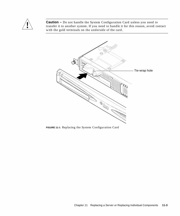
Caution – Do not handle the System Configuration Card unless you need to
transfer it to another system. If you need to handle it for this reason, avoid contact
with the gold terminals on the underside of the card.
FIGURE 11-1 Replacing the System Configuration Card
Tie-wrap hole
Chapter 11 Replacing a Server or Replacing Individual Components 11-3

11.2 Field Replaceable Units
Note – The procedures in this chapter for replacing faulty components are for the
attention of qualified service engineers only. If you need to replace a component,
contact your local Sun sales representative who will put you in touch with the Sun
Enterprise Service branch for your area. You can then arrange to return the system to
Sun for repair under the terms of your warranty. Or alternatively you can order the
components and have them installed by your own qualified service engineers.
TABLE 11-1 lists the field replaceable units (FRUs) available for the Sun Fire V120 and
Netra 120 servers. FRUs are hardware components that are normally installed by
Sun engineers and not by users.
For instructions about how to install DIMMs, see Chapter 4.
TABLE 11-1 FRUs Available for the Sun Fire V120 and Netra 120 Servers
Component Part Number
Internal CD-ROM (including cabling and paddle board) F370-4278
Internal DVD-ROM (including cabling and paddle board) F540-5014
18 Gbyte hard disk drive F540-4177
36 Gbyte hard disk drive F540-4689
256 Mbyte DIMM F370-4237
512 Mbyte DIMM F370-4281
1 Gbyte DIMM F370-4874
System board (containing 550 MHz CPU) F375-3064
System board (containing 650 MHz CPU) F375-3065
Memory card reader (for the system configuration card) F370-4290
AC power supply F300-1488
DC power supply F300-1489
Rear fan subassembly (containing Fans 1 and 2) F540-5198
System configuration card F370-4285
Fan 3 (CPU fan) F370-4860
NVRAM chip (including carrier) F100-6889
11-4 Sun Fire V120 and Netra 120 Server User’s Guide • December 2001
11.3 Replacing the Memory Card Reader forthe System Configuration Card
Caution – The procedure below is for the attention of qualified service engineers
only. Before touching or replacing any components inside the server, disconnect all
cables and follow the instructions in Section 4.2, “Opening the Server” on page 4-4
which tell you how to open the system. Always place the server on a grounded ESD
pad and wear a properly grounded antistatic wrist strap.
1. Open the server by following the instructions in Chapter 4 (“Opening the Server”on page 4-4).
Make sure all external cables are disconnected and pay particular attention to the
information about how to prevent electrostatic discharge from your body from
damaging the components of the server.
2. With the server open and seated on top of an ESD pad, and with a properlygrounded antistatic wrist strap on your wrist, remove the power cable from theconnector on the memory card reader board (see FIGURE 11-2).
3. Unscrew the screws fixing the memory card reader board into the top of theCD-ROM drive bay (see FIGURE 11-2).
Do not discard the screws.
4. Remove the old system configuration card reader.
5. Position the new memory card reader board by lining up its fixing holes with theholes in the top of the CD-ROM drive enclosure.
6. Insert and tighten the fixing screws.
7. Attach the power cable to the memory card reader board.
Chapter 11 Replacing a Server or Replacing Individual Components 11-5

FIGURE 11-2 Removing the System Configuration Card Reader
Cardreader’scableconnector
11-6 Sun Fire V120 and Netra 120 Server User’s Guide • December 2001
11.4 Replacing the DVD or CD-ROM Drive,Cable, and Paddleboard
Caution – The procedure below is for the attention of qualified service engineers
only. Before touching or replacing any components inside the server, disconnect all
cables and follow the instructions in Section 4.2, “Opening the Server” on page 4-4
which tell you how to open the server. Always place the server on a grounded ESD
pad and wear a properly grounded antistatic wrist strap.
1. Open the server by following the instructions in Chapter 4 (“Opening the Server”on page 4-4).
Make sure all external cables are disconnected and pay particular attention to the
information about how to prevent electro-static discharge from your body from
damaging the components of the server.
2. With the system open and seated on top of an ESD pad, and with a properlygrounded antistatic wrist strap on your wrist, do the following:
a. Remove the old DVD or CD-ROM drive from the chassis (see Section 4.4.2,“Removing a DVD or CD-ROM Drive” on page 4-9).
b. If you have a full-length PCI card installed, remove it (see Section 4.6.2,“Removing a PCI Card” on page 4-14).
3. Disconnect the memory card reader board’s power cable from the system board(see FIGURE 11-3).
4. From the chassis base, unscrew the plastic bracket that secures the paddleboard(and that also provides support for a full-length PCI card).
5. Lift the paddleboard (with its ribbon cable) out of its guides at the back of theDVD or CD-ROM drive enclosure and discard it.
6. Connect the new IDE ribbon cable to the system board with the cable extendingaway from the system board and towards the DVD or CD-ROM drive (seeFIGURE 11-3).
7. Now connect the ribbon cable to the connector on the paddleboard.
8. Insert the paddleboard into the guides at the back of the DVD or CD-ROM driveenclosure in the chassis.
Do not replace the plastic bracket yet.
Chapter 11 Replacing a Server or Replacing Individual Components 11-7

9. Reconnect the memory card reader board’s power cable to its connector on thesystem board.
10. Insert the new DVD or CD-ROM drive (see Section 4.4.1, “Installing a DVD orCD-ROM Drive” on page 4-7).
11. Now replace the plastic bracket that secures the paddleboard, and screw it into thechassis base (see FIGURE 11-3).
12. Replace the full-length PCI card if you removed it earlier (see Section 4.6.1,“Installing a PCI Card” on page 4-11).
13. Replace the system cover and tighten the captive screw (see FIGURE 4-9 inSection 4.7, “Replacing the Server’s Top Cover” on page 4-14).
FIGURE 11-3 Replacing the Paddleboard at the Back of the DVD or CD-ROM DriveEnclosure
Cardreader’scableconnector
Plasticbracket
11-8 Sun Fire V120 and Netra 120 Server User’s Guide • December 2001
11.5 Replacing the NVRAM Chip
Caution – The procedure below is for the attention of qualified service engineers
only. Before touching or replacing any components inside the server, disconnect all
cables and follow the instructions in Section 4.2, “Opening the Server” on page 4-4
which tell you how to open the system. Always place the system on a grounded ESD
pad and wear a properly grounded antistatic wrist strap.
The NVRAM chip on the server’s system board contains a lithium battery that in
time may need replacing. If you see the following message on your console when
you boot the server:
Warning -- Real-Time-Clock (and NVRAM) battery is low
order a new NVRAM chip (part number: F100-6889) from your local Sun sales
representative. Take note of the caution below.
Caution – There is a danger of explosion if the NVRAM chip is incorrectly replaced.
Replace it only with a component of the same type as the used one (part number
F100-6889). To replace the chip, follow any instructions supplied with the new
component. Dispose of the used component according to the manufacturer’s
instructions.
The NVRAM chip is located in a carrier between the rear fan subassembly and the
DIMM sockets on the system board (see FIGURE 11-4). To replace it:
1. Make a note of the current settings of the environment parameters diag-switch?and diag-level . You will need these values to carry out Step 5.
To check the setting for diag-switch? , type:
To check the setting for diag-level , type:
ok printenv diag-switch?
ok printenv diag-level
Chapter 11 Replacing a Server or Replacing Individual Components 11-9

2. Open the server by following the instructions in Section 4.2, “Opening theServer” on page 4-4).
Make sure all external cables are disconnected and pay particular attention to the
information about how to prevent electrostatic discharge from your body from
damaging the components of the server.
FIGURE 11-4 The Location of the NVRAM Chip
3. Carefully take the NVRAM chip carrier lengthwise between your thumb andforefinger and pull it out of its socket (see FIGURE 11-5).
4. Holding the new NVRAM chip carrier in a similar fashion between your thumband forefinger, position it over the socket and press firmly until the connectorsengage.
NVRAMchip
DIMMsockets
Hard disks
11-10 Sun Fire V120 and Netra 120 Server User’s Guide • December 2001

5. When you have reconnected the cables and powered the server on, type thefollowing at the ok prompt, using the values you noted in Step 1:
FIGURE 11-5 Replacing the NVRAM Chip
6. Replace the system cover and tighten the captive screw (see FIGURE 4-9 inSection 4.7, “Replacing the Server’s Top Cover” on page 4-14).
ok reset-allok setenv diag-switch? noted_valueok setenv diag-level noted_valueok reset-all
Chapter 11 Replacing a Server or Replacing Individual Components 11-11

11.6 Replacing the System Board
Caution – The procedure below is for the attention of qualified service engineers
only. Before touching or replacing any components inside the server, disconnect all
cables and follow the instructions in Section 4.2, “Opening the Server” on page 4-4
which tell you how to open the server. Always place the server on a grounded ESD
pad and wear a properly grounded antistatic wrist strap.
To perform the steps in this section, you need a 5mm nut-spinner to remove and
replace the SCSI pillars on the rear of the chassis.
11.6.1 Removing the Old System Board
1. Open the server by following the instructions in Section 4.2, “Opening theServer” on page 4-4.
Make sure all external cables are disconnected and pay particular attention to the
information about how to prevent electro-static discharge from your body from
damaging the components of the server.
2. With the server open and seated on top of an ESD pad, and with a properlygrounded antistatic wrist strap on your wrist, do the following:
a. Disconnect all power supply cables from the system board.
b. Disconnect the DVD or CD-ROM ribbon cable from the system board.
c. Disconnect the memory card reader cable from the system board.
3. Remove the server’s front bezel.
4. Remove the hard disk drives in the server (see Section 4.1, “Installing andRemoving Hot-Pluggable SCSI Hard Disk Drives” on page 4-2).
5. Remove the PCI card if you have one installed (see Section 4.6.2, “Removing a PCICard” on page 4-14).
6. Remove the DIMMs from their slots (see Section 4.5, “Installing and RemovingMemory” on page 4-9).
7. Remove the rear fan subassembly (see Section 11.8, “Replacing the Rear FanSubassembly (Fans 1 and 2)” on page 11-19).
11-12 Sun Fire V120 and Netra 120 Server User’s Guide • December 2001

8. Unplug the power cable for Fan 3 (see FIGURE 11-6) and undo the two screws thatfasten the ducting assembly to the chassis.
FIGURE 11-6 Unplugging and Removing the Fan 3 Assembly
9. Pull the fan and ducting assembly away from the chassis (see FIGURE 11-6).
10. Unscrew the system board protection/support block (between the PSU and HardDisk Drive bay 1) and slide it back as far as the PSU (see FIGURE 11-7).
11. Unscrew and remove the PCI card slide retainer (see FIGURE 11-7).
12. Unscrew all system board fixing screws (see FIGURE 11-7).
13. Unscrew the SCSI pillars on the back panel (see FIGURE 11-7).
14. Slide the system board towards the front of the chassis so that the SCSI, Ethernetand Serial connectors come free from the chassis.
15. Carefully lift out the system board.
Chapter 11 Replacing a Server or Replacing Individual Components 11-13
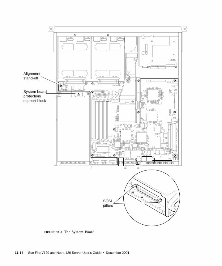
FIGURE 11-7 The System Board
SCSIpillars
System boardprotection/support block
Alignmentstand-off
11-14 Sun Fire V120 and Netra 120 Server User’s Guide • December 2001

11.6.2 Installing the New System Board
Note – The system board contains a jumper (JP8) that identifies the hardware to the
system software as either a Sun Fire V120 or a Netra 120. The factory default setting
for JP8 on FRU replacement system boards (F375-3064 and F275-3065) identifies
them as Sun Fire V120s. Before installing a new system board, make sure that the
setting for JP8 is correct for the model of system you are installing it into. To check
the jumper settings, see Appendix D. Do not alter any other jumper settings.
1. Check that the setting for jumper JP8 on the new system board is correct for themodel of server you are installing it into (see Appendix D).
2. Insert the new system board at an angle, and locate it so that the SCSI, Ethernet,and serial connectors are firmly positioned in their slots at the rear of the chassis.
3. Now position the system board on the alignment stand-off between the PSU fanand hard disk drive bay 1 (see FIGURE 11-7).
4. Insert the SCSI pillars (see FIGURE 11-7) and replace their screws loosely.
5. Insert all system board fixing screws loosely (see FIGURE 11-7). Do not put anyscrews in the holes for the PCI card slide retainer.
6. Tighten up the SCSI pillars, then tighten all the other screws.
7. Replace the PCI card slide retainer.
8. Replace the DIMMs that you removed from the old system board (see Section 4.5,
“Installing and Removing Memory” on page 4-9).
9. Replace the rear fan assembly (see Section 11.8, “Replacing the Rear FanSubassembly (Fans 1 and 2)” on page 11-19).
Chapter 11 Replacing a Server or Replacing Individual Components 11-15
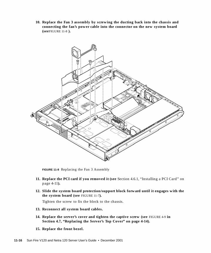
10. Replace the Fan 3 assembly by screwing the ducting back into the chassis andconnecting the fan’s power cable into the connector on the new system board(seeFIGURE 11-8 ).
FIGURE 11-8 Replacing the Fan 3 Assembly
11. Replace the PCI card if you removed it (see Section 4.6.1, “Installing a PCI Card” on
page 4-11).
12. Slide the system board protection/support block forward until it engages with thethe system board (see FIGURE 11-7).
Tighten the screw to fix the block to the chassis.
13. Reconnect all system board cables.
14. Replace the server’s cover and tighten the captive screw (see FIGURE 4-9 inSection 4.7, “Replacing the Server’s Top Cover” on page 4-14).
15. Replace the front bezel.
11-16 Sun Fire V120 and Netra 120 Server User’s Guide • December 2001

11.7 Replacing the Power Supply Unit
Caution – The procedure below is for the attention of qualified service engineers
only. Before touching or replacing any components inside the server, disconnect all
cables and follow the instructions in Section 4.2, “Opening the Server” on page 4-4
which tell you how to open the server. Always place the server on a grounded ESD
pad and wear a properly grounded antistatic wrist strap.
1. Open the server by following the instructions in Section 4.2, “Opening theServer” on page 4-4.
Make sure you disconnect all external cables and pay particular attention to the
information about how to prevent electro-static discharge from your body from
damaging the components of the server.
2. With the server open and seated on top of an ESD pad, and with a properlygrounded antistatic wrist strap on your wrist, disconnect the power supply cablesfrom the system board.
3. Undo the two rear fixing screws (see FIGURE 11-9).
4. Move the power supply unit (PSU) towards the front of the system to release itfrom the location tabs in the base.
Lift it away from the chassis.
5. Lift the new PSU over the location tabs and slide it backwards into place (seeFIGURE 11-9).
6. Secure the two rear fixing screws.
7. Connect the power supply cables to the connectors on the system board.
8. Replace the server’s cover and tighten the captive screw (see FIGURE 4-9 inSection 4.7, “Replacing the Server’s Top Cover” on page 4-15).
Chapter 11 Replacing a Server or Replacing Individual Components 11-17
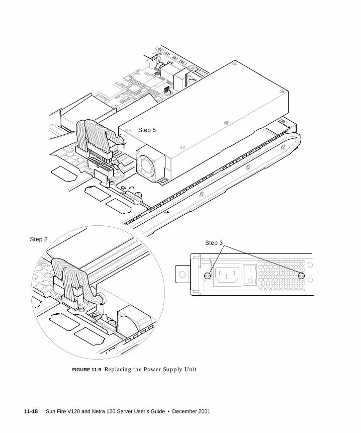
FIGURE 11-9 Replacing the Power Supply Unit
Step 2Step 3
Step 5
11-18 Sun Fire V120 and Netra 120 Server User’s Guide • December 2001
11.8 Replacing the Rear Fan Subassembly(Fans 1 and 2)
Caution – The procedure below is for the attention of qualified service engineers
only. Before touching or replacing any components inside the server, disconnect all
cables and follow the instructions in Section 4.2, “Opening the Server” on page 4-4
which tell you how to open the server. Always place the server on a grounded ESD
pad and wear a properly grounded antistatic wrist strap.
1. Open the server by following the instructions in Section 4.2, “Opening theServer” on page 4-4.
Make sure you disconnect all external cables and pay particular attention to the
information about how to prevent electro-static discharge from your body from
damaging the components of the server.
2. With the server open and seated on top of an ESD pad, and with a properlygrounded antistatic wrist strap on your wrist, disconnect the old subassembly’spower cables from the system board (see FIGURE 11-10).
3. Lift out the old subassembly and discard it.
4. Insert the new fan subassembly into its bay in the chassis.
5. Connect the fan cables to the system board (see FIGURE 11-10).
6. Replace the server’s cover and tighten the captive screw (see FIGURE 4-9 inSection 4.7, “Replacing the Server’s Top Cover” on page 4-14).
Chapter 11 Replacing a Server or Replacing Individual Components 11-19

FIGURE 11-10 Replacing the Rear Fan Subassembly (Fans 1 and 2)
11-20 Sun Fire V120 and Netra 120 Server User’s Guide • December 2001
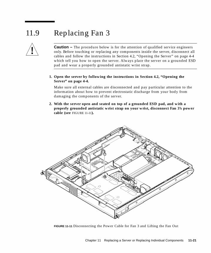
11.9 Replacing Fan 3
Caution – The procedure below is for the attention of qualified service engineers
only. Before touching or replacing any components inside the server, disconnect all
cables and follow the instructions in Section 4.2, “Opening the Server” on page 4-4
which tell you how to open the server. Always place the server on a grounded ESD
pad and wear a properly grounded antistatic wrist strap.
1. Open the server by following the instructions in Section 4.2, “Opening theServer” on page 4-4.
Make sure all external cables are disconnected and pay particular attention to the
information about how to prevent electrostatic discharge from your body from
damaging the components of the server.
2. With the server open and seated on top of a grounded ESD pad, and with aproperly grounded antistatic wrist strap on your wrist, disconnect Fan 3’s powercable (see FIGURE 11-11).
FIGURE 11-11 Disconnecting the Power Cable for Fan 3 and Lifting the Fan Out
Chapter 11 Replacing a Server or Replacing Individual Components 11-21

3. Take the fan between your forefinger and thumb and lift it out of its cradle.
4. Take the new fan and position it into the fan’s cradle.
5. Connect the new fan’s power cable to its connector on the system board.
6. Replace the server’s cover and tighten the captive screw (see FIGURE 4-9 inSection 4.7, “Replacing the Server’s Top Cover” on page 4-14).
11-22 Sun Fire V120 and Netra 120 Server User’s Guide • December 2001
PART IV Appendixes


APPENDIX A
Installing and Removing a SCSIHard Disk Drive with SolarisRunning
This appendix contains the following sections:
■ Section A.1, “Installing a SCSI Hard Disk Drive With Solaris Running” on
page A-2
■ Section A.2, “Removing a SCSI Hard Disk Drive With Solaris Running” on
page A-4
A-1
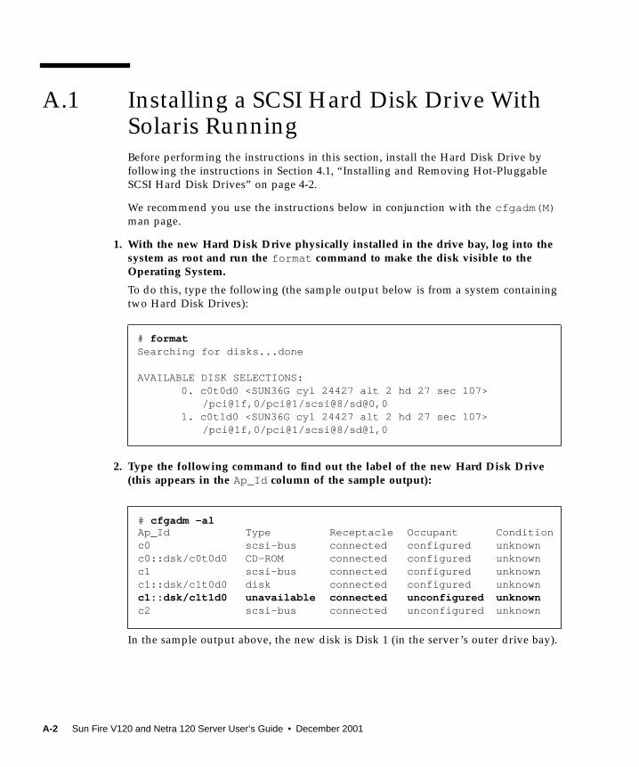
A.1 Installing a SCSI Hard Disk Drive WithSolaris RunningBefore performing the instructions in this section, install the Hard Disk Drive by
following the instructions in Section 4.1, “Installing and Removing Hot-Pluggable
SCSI Hard Disk Drives” on page 4-2.
We recommend you use the instructions below in conjunction with the cfgadm(M)man page.
1. With the new Hard Disk Drive physically installed in the drive bay, log into thesystem as root and run the format command to make the disk visible to theOperating System.
To do this, type the following (the sample output below is from a system containing
two Hard Disk Drives):
2. Type the following command to find out the label of the new Hard Disk Drive(this appears in the Ap_Id column of the sample output):
In the sample output above, the new disk is Disk 1 (in the server’s outer drive bay).
# formatSearching for disks...done
AVAILABLE DISK SELECTIONS:0. c0t0d0 <SUN36G cyl 24427 alt 2 hd 27 sec 107>
/pci@1f,0/pci@1/scsi@8/sd@0,01. c0t1d0 <SUN36G cyl 24427 alt 2 hd 27 sec 107>
/pci@1f,0/pci@1/scsi@8/sd@1,0
# cfgadm -alAp_Id Type Receptacle Occupant Conditionc0 scsi-bus connected configured unknownc0::dsk/c0t0d0 CD-ROM connected configured unknownc1 scsi-bus connected configured unknownc1::dsk/c1t0d0 disk connected configured unknownc1::dsk/c1t1d0 unavailable connected unconfigured unknownc2 scsi-bus connected unconfigured unknown
A-2 Sun Fire V120 and Netra 120 Server User’s Guide • December 2001

3. Connect the new disk logically to the Operating System by typing the followingcommand, specifying the correct Ap_Id label for the disk you have installed (inthis sample command the Ap_Id label is for Disk 1):
4. Confirm that the disk is now connected and configured by typing:
5. If you want to check that the disks are active, follow the instructions inSection 10.2.1, “Using the probe-scsi Command To Confirm That Hard Disk DrivesAre Active” on page 10-8
The disk is now available to be mounted for operation.
# cfgadm -c configure c1::dsk/c1t1d0
# cfgadm -alAp_Id Type Receptacle Occupant Conditionc0 scsi-bus connected configured unknownc0::dsk/c0t0d0 CD-ROM connected configured unknownc1 scsi-bus connected configured unknownc1::dsk/c1t0d0 disk connected configured unknownc1::dsk/c1t1d0 disk connected configured unknownc2 scsi-bus connected unconfigured unknown
Appendix A Installing and Removing a SCSI Hard Disk Drive with Solaris Running A-3

A.2 Removing a SCSI Hard Disk Drive WithSolaris RunningIf you are removing a Hard Disk Drive while the Operating System is still running,
you must remove the drive logically from the Operating System before removing it
physically. Follow the instructions in this section, then remove the Hard Disk Drive
physically by following the instructions in Section 4.1, “Installing and Removing
Hot-Pluggable SCSI Hard Disk Drives” on page 4-2.
We recommend you use the instructions below in conjunction with the cfgadm(M)man page.
1. Check that the Hard Disk Drive you want to remove is visible to the OperatingSystem.
To do this, type the following:
2. Next find out the correct Ap_Id label for the Hard Disk Drive that you want toremove.
To do this, type the following:
# formatSearching for disks...done
AVAILABLE DISK SELECTIONS:0. c0t0d0 <SUN36G cyl 24427 alt 2 hd 27 sec 107>
/pci@1f,0/pci@1/scsi@8/sd@0,01. c0t1d0 <SUN36G cyl 24427 alt 2 hd 27 sec 107>
/pci@1f,0/pci@1/scsi@8/sd@1,0
# cfgadm -alAp_Id Type Receptacle Occupant Conditionc0 scsi-bus connected configured unknownc0::dsk/c0t0d0 CD-ROM connected configured unknownc1 scsi-bus connected configured unknownc1::dsk/c1t0d0 disk connected configured unknownc1::dsk/c1t1d0 disk connected configured unknownc2 scsi-bus connected unconfigured unknown
A-4 Sun Fire V120 and Netra 120 Server User’s Guide • December 2001

Note – Before proceeding, you must remove the Hard Disk Drive from all of its
software mount positions and delete any swap areas in use on the disk. If the disk is
the system’s boot device, do not proceed further with these instructions. Do not
attempt to unconfigure the boot disk.
3. Now unconfigure the Hard Disk Drive that you intend to remove.
To do this, use the unconfigure command and specify the device you intend to
remove. For example, if it is Disk 1, type:
4. Check that the device is now “unconfigured”.
To do this type:
5. Confirm that the Hard Disk Drive you want to remove from the server is no longervisible to the Operating System.
To do this, type the following:
6. It is now safe to remove the Hard Disk Drive physically from the server withoutshutting down the Operating System.
To do this, follow the instructions in Section 4.1, “Installing and Removing Hot-
Pluggable SCSI Hard Disk Drives” on page 4-2.
# cfgadm -c unconfigure c1::dsk/c1t1d0
# formatSearching for disks...done
AVAILABLE DISK SELECTIONS:0. c0t0d0 <SUN36G cyl 24427 alt 2 hd 27 sec 107>
/pci@1f,0/pci@1/scsi@8/sd@0,0
# cfgadm -alAp_Id Type Receptacle Occupant Conditionc0 scsi-bus connected configured unknownc0::dsk/c0t0d0 CD-ROM connected configured unknownc1 scsi-bus connected configured unknownc1::dsk/c1t0d0 disk connected configured unknownc1::dsk/c1t1d0 unavailable connected unconfigured unknownc2 scsi-bus connected unconfigured unknown
Appendix A Installing and Removing a SCSI Hard Disk Drive with Solaris Running A-5

A-6 Sun Fire V120 and Netra 120 Server User’s Guide • December 2001
APPENDIX B
Reinstalling the Solaris OperatingEnvironment
This appendix contains the following sections:
■ Section B.1, “Reinstalling Solaris” on page B-2
■ Section B.2, “Reinstalling the Lights-Out Management Software” on page B-2
B-1

B.1 Reinstalling SolarisThe Sun Fire V120 and Netra 120 servers are supplied with the Solaris operating
environment preinstalled.
If for any reason you decide to reinstall the Solaris operating environment (for
example, if you need to repartition your root disk or recover from a failure), obtain
the Solaris media kit from your Sun sales representative, and follow the instructions
in the Solaris Installation Guide and the Solaris Advanced Installation Guide.
For information about the versions of Solaris supported by the Sun Fire V120 and
the Netra 120, refer to the Product Notes supplied with the server.
B.2 Reinstalling the Lights-Out ManagementSoftwareIf you reinstall the Solaris operating environment and you intend to use the Lights-
Out Management (LOM) facilities, you must re-install the Lights-Out Management
software from the CD entitled Software Supplement for the Solaris OperatingEnvironment. This CD is included in the Solaris media kit. For the location of the
LOM packages on the CD, refer to the Sun Hardware Platform Guide for the release of
Solaris that you are using.
Note – If you do not reinstall the LOM software, the LOM facilities will not be
available and layered applications that are dependent on them (for example, the Sun
Management Center software) will not function correctly.
B-2 Sun Fire V120 and Netra 120 Server User’s Guide • December 2001

APPENDIX C
Configuring the LOM Device Driver
This appendix describes the driver parameters you can set in the lom.confconfiguration file. Some of these parameters are also configurable by means of the
LOM-specific Solaris commands described in Chapter 9.
The appendix contains the following sections:
■ Section C.1, “The LOM Device Driver” on page C-2
■ Section C.2, “Configuring the LOM Device Driver” on page C-3
C-1
C.1 The LOM Device DriverThe LOM driver software included in Solaris is as follows:
■ /platform/sun4u/kernel/drv/lom (the lom driver (32-bit))
■ /platform/sun4u/kernel/drv/sparcv9/lom (the lom driver (64-bit))
■ /platform/sun4u/kernel/drv/lom.conf ( the driver configuration file)
C-2 Sun Fire V120 and Netra 120 Server User’s Guide • December 2001
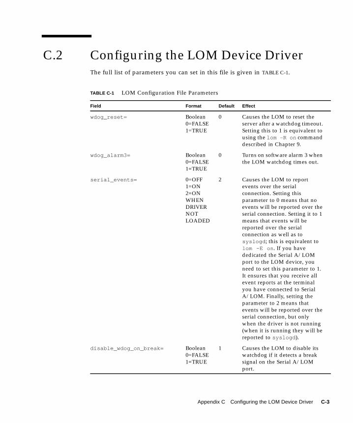
C.2 Configuring the LOM Device DriverThe full list of parameters you can set in this file is given in TABLE C-1.
TABLE C-1 LOM Configuration File Parameters
Field Format Default Effect
wdog_reset= Boolean
0=FALSE
1=TRUE
0 Causes the LOM to reset the
server after a watchdog timeout.
Setting this to 1 is equivalent to
using the lom -R on command
described in Chapter 9.
wdog_alarm3= Boolean
0=FALSE
1=TRUE
0 Turns on software alarm 3 when
the LOM watchdog times out.
serial_events= 0=OFF
1=ON
2=ON
WHEN
DRIVER
NOT
LOADED
2 Causes the LOM to report
events over the serial
connection. Setting this
parameter to 0 means that no
events will be reported over the
serial connection. Setting it to 1
means that events will be
reported over the serial
connection as well as to
syslogd ; this is equivalent to
lom -E on . If you have
dedicated the Serial A/LOM
port to the LOM device, you
need to set this parameter to 1.
It ensures that you receive all
event reports at the terminal
you have connected to Serial
A/LOM. Finally, setting the
parameter to 2 means that
events will be reported over the
serial connection, but only
when the driver is not running
(when it is running they will be
reported to syslogd ).
disable_wdog_on_break= Boolean
0=FALSE
1=TRUE
1 Causes the LOM to disable its
watchdog if it detects a break
signal on the Serial A/LOM
port.
Appendix C Configuring the LOM Device Driver C-3

disable_wdog_on_panic= Boolean
0=FALSE
1=TRUE
1 Causes the LOM to try to
disable its watchdog after a
system panic.
faulty_voltage_shutdown= Boolean
0=FALSE
1=TRUE
1 Causes the LOM to attempt first
to shut down the system and, if
that fails, to power off the
system in the event of a fatal
problem with the supply rails.
enclosure_warning_temp= oC 67 Specifies the temperature at
which the LOM generates a
temperature warning.
over_temperature_shutdown= Boolean
0=FALSE
1=TRUE
1 Causes the LOM to attempt to
shut down the system, or to
power it off, if the enclosure
temperature exceeds the level
specified for the
enclosure_shutdown_tempparameter.
enclosure_shutdown_temp= oC 72 Specifies the enclosure
temperature above which the
LOM attempts to shut the
system down, or, if this fails, to
power the system off. (The LOM
device will only attempt to do
either of these if
over_temperature_shutdown is
set to 1.)
serial_security= Boolean
0=FALSE
1=TRUE
1 Enables and disables the LOM
user security facilities even if
user security has been
configured. You can use this
parameter to set up users again
if your users have forgotten
their passwords.
TABLE C-1 LOM Configuration File Parameters (Continued)
Field Format Default Effect
C-4 Sun Fire V120 and Netra 120 Server User’s Guide • December 2001
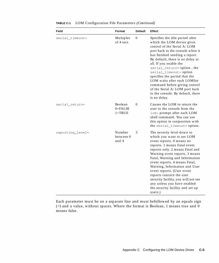
Each parameter must be on a separate line and must befollowed by an equals sign
(=) and a value, without spaces. Where the format is Boolean, 1 means true and 0
means false.
serial_timeout= Multiples
of 4 secs
0 Specifies the idle period after
which the LOM device gives
control of the Serial A/LOM
port back to the console when it
has finished sending a report.
By default, there is no delay at
all. If you enable the
serial_return= option , the
serial_timeout= option
specifies the period that the
LOM waits after each LOMlite
command before giving control
of the Serial A/LOM port back
to the console. By default, there
is no delay.
serial_return= Boolean
0=FALSE
1=TRUE
0 Causes the LOM to return the
user to the console from the
lom> prompt after each LOM
shell command. You can use
this option in conjunction with
the serial_timeout= option.
reporting_level= Number
between 0
and 4
3 The severity level down to
which you want to see LOM
event reports. 0 means no
reports. 1 means Fatal event
reports only. 2 means Fatal and
Warning event reports. 3 means
Fatal, Warning and Information
event reports. 4 means Fatal,
Warning, Information and User
event reports. (User event
reports concern the user
security facility, you will not see
any unless you have enabled
the security facility and set up
users.)
TABLE C-1 LOM Configuration File Parameters (Continued)
Field Format Default Effect
Appendix C Configuring the LOM Device Driver C-5

C-6 Sun Fire V120 and Netra 120 Server User’s Guide • December 2001
APPENDIX D
System Board Jumper Settings
This appendix describes the functions and factory-default settings of the jumpers on
the system board of the Sun Fire V120 and Netra 120 servers.
D-1

The Netra T1 server’s system board contains several jumpers.
We do not recommend you change the jumper settings. However, for reference, the
factory-default settings are listed in TABLE D-1, and the locations of the jumpers are
shown in FIGURE D-1 (which also illustrates the default settings).
TABLE D-1 Factory-Default Jumper Settings
Jumper Default Setting Description
JP8 1-2 (Open)
3-4 (Fitted)
This is the factory default setting for replacement system
boards. It identifies the system to OpenBoot PROM and Solaris
as a Sun Fire V120 server. If you are installing a new system
board for a Sun Fire V120, make sure that the jumpers match
this setting.
1-2 (Fitted)
3-4 (Open)
This setting identifies the system to OpenBoot PROM and
Solaris as a Netra 120 server. If you are installing a new system
board into a Netra 120, you must set the jumpers on the
replacement board to match this setting. (Note that the factory
default setting is for the Sun Fire V120, not for the Netra 120
system. This is why you must change the setting before
installing the new board.)
JP7 1-2 (Open)
3-4 (Open)
5-6 (Fitted)
This jumper setting tells the system that its main processor is a
550 MHz CPU. Do not alter this setting. It is correct for the CPU
on your system board.
1-2 (Open)
3-4 (Fitted)
5-6 (Open)
This jumper setting tells the system that its main processor is a
650 MHz CPU. Do not alter this setting. It is correct for the CPU
on your system board.
JP9 1-2 (Fitted) This jumper is for use by Sun engineers in the development of
OBP software. Do not alter its setting.
JP13 1-2 (Open) This jumper is for use by Sun service engineers. It resets the
LOM device. Do not alter this setting.
JP14 1-2 (Open) This jumper is for use by Sun service engineers in the event that
the LOM device on the system board is broken. The default
setting is Open. If you alter this setting to Fitted, then, if the
LOM is broken, you can use the On/Standby rocker switch to
power the system on (or down to standby mode). Note that the
power signals from the On/Standby switch pass through the
LOM device, and that setting this jumper to Fitted causes the
signals from the rocker switch to bypass the LOM.
D-2 Sun Fire V120 and Netra 120 Server User’s Guide • December 2001

JP15 1-2 (Open) This jumper is for use by Sun service engineers only. It enables
and disables emergency recovery of the LOM firmware. In its
default state (Open), recovery of the firmware is not possible.
However, service engineers might need to follow a special
procedure to recover the firmware for the LOM, and this
procedure involves temporarily changing the setting of JP15 to
Fitted. Afterwards, it must always be returned to Open.
JP16 1-2 (Fitted) This jumper write-enables the OBP software to allow you to
update it. If you need to protect the OBP software from being
over-written, change the jumper setting to Open.
JP17 1-2 (Open) This jumper tells the DVD or CD-ROM drive (if one is installed)
that it is a Master ATA device. For the DVD and CD-ROM
drives currently available for the Sun Fire V120 and Netra 120
systems, this jumper must be Open.
TABLE D-1 Factory-Default Jumper Settings (Continued)
Jumper Default Setting Description
Appendix D System Board Jumper Settings D-3

FIGURE D-1 System Board Jumper Locations and Default Settings
JP16
JP9
JP15
JP13JP14
JP17
Pin 1
JP7 (setting for550MHz CPU)
Pin 5
JP7 (setting for650MHz CPU)
Pin 1
Pin 1
Pin 3
JP8 (setting forNetra 120)
JP8 (setting forSun Fire V120)
D-4 Sun Fire V120 and Netra 120 Server User’s Guide • December 2001

Index
AAC power
warnings, 6-3
acoustic noise, 1-9
alarms
checking the status of, 9-5
alarms, setting, 8-21, 9-11
altitude, 1-9
ATM cards (optional), 1-5
automatic server restart, 9-8
Bback panel, 1-7, 10-12
BTU rating, 2-2
Ccabling, 3-3, 6-2, 6-3
CD-ROM drive, 4-6
cable, 11-7
enclosure, 11-7
installing (as an X-option), 4-7
ordering, 1-5
paddleboard, 11-7
replacing (as a FRU), 11-7
configuration, 7-2
connecting the cables, 6-2 to 6-9
cooling (heat dissipation), 2-4
cover
replacement, 4-14
crossover cable, 6-7, 6-8
current
in-rush, 2-2
operating, 2-2
DDB-25 adapter, 6-7
DB-9 adapter, 6-8
DC connection materials, 3-2
DC connector cage clamp, 3-5
DC input power cable, 3-6
strain relief housing, 3-7
DC input power cables, 3-3
DC power inlets, 1-7
diagnostics, 10-2
obdiag, 10-3
POST, 10-2
probe-ide, 10-9
probe-scsi and probe-scsi-all, 10-8
SunVTS, 10-5
watch-net and watch-net-all, 10-9
dimensions, 1-3
DIMMs
adding and removing, 4-9
location, 4-6
part numbers, 1-5
domain name, 7-5
drive bay grilles, 4-2
DVD drive, 4-6, 4-7
Index-1

Eearthquake tolerance, 1-9
electro-magnetic compatibility, 1-9
environment, 1-9
environmental compliance, 1-9
Ethernet
connection, 7-4
ports, 1-2
event log, viewing, 8-10
Ffans, 8-23
checking the status, 9-3
power supply, 8-23
fault LED, 8-20
checking the status of (remotely), 9-5
turning on, 8-22
field replaceable units, 11-4
filtering devices, external, 3-2
flooring, 1-10
front bezel, 4-6
removing, 4-2
front panel, 1-6, 10-12
Ggrille
drive bay, 4-2
grounding
DC requirements, 3-3
grounding studs, 1-7
Hhard disk drive, 1-3, 4-6
installing, 4-2, A-2
removing, 4-2, A-4
heat dissipation, 2-4
host name, 7-5
displaying, 8-22
Iinput voltage range, 2-2
in-rush current, 2-2
installation
CD-ROM drive, 4-7
CD-ROM with cable and paddleboard, 11-7
DIMMs, 4-9
hard disk drives, 4-2, A-2
memory card reader, 11-5
new system board, 11-15
PCI cards, 4-11
rack mounting, 5-1
rear fan subassembly, 11-19
replacement NVRAM chip, 11-9
two-post relay rack, 5-12
insulated conductors, 3-3
internal circuit breakers, 9-3
Jjumpers
factory default settings, D-2
locating on the system board, D-4
LLEDs
Ethernet link indicators, 10-13
power indicator, 10-12
Lights Out Management (LOM)
commands, 8-21
displaying the host name, 8-22
displaying the version number of the LOM
device, 8-22
monitoring the system, 9-2 to 9-7
online documentation, 9-2
parameters, C-3
power supply unit, 9-2
powering up the system, 8-22
returning control of serial connection to
console, 8-22
sample Event Log, 8-10, 9-7
setting the alarms, 8-21, 9-11
setting up named users, 8-13 to 8-17
stopping event reporting, C-3
turning the fault LED on, 8-22
updating component status, 8-21
viewing the LOM’s Event Log, 8-10
locating system components, 4-1
Index-2 Sun Fire V120 and Netra 120 Server User’s Guide • December 2001

log, viewing, 8-10
LOM device
configuration variables, 8-17
separating from the console on Serial A, 8-19
sharing Serial A between the console and the
LOM device, 8-20
upgrading firmware, 9-13
version number, 8-22
LOM device driver
configuring, C-1 to C-5
LOM interface
backwards compatibility, 9-13
escape sequence, 9-12
Mmemory
installing additional memory, 4-9
Microsoft Windows
using Windows Hyperterminal, 6-11
NName Server, 7-5
network install server
creating, B-2
null modem cable, 6-7, 6-8
NVRAM chip
location on system board, 11-10
part number, 11-9
replacing, 11-9
OOn/Standby switch, 7-7
OpenBoot diagnostics, 10-3
opening the system, 4-4
operating current, 2-2
operating environment, 1-9
output message
watch-net all diagnostic, 10-10
watch-net diagnostic, 10-10
Ppart numbers
customer-installable hardware and software
options, 1-5
PCI card
installing, 4-14
PCI cards
installing, 4-11
part numbers of available cards, 1-5
removing, 4-14
pinout
serial port, 6-5, 6-6
POST diagnostics, 10-2
power
DC supply and ground, 3-3
factor, 2-2
requirements, 2-2
switch, 7-7, 8-3
power consumption, 2-3
power LED, 10-12
power supply
fan, 8-23
monitoring PSU and fans, 8-8
power supply unit, 9-2
powering on, 7-7
problems
booting (OBP initialization aborts), 10-11
cannot set up a console connection to the
server, 10-10
displaying the lom> prompt or the Solaris
prompt, 10-11
getting to the LOM prompt, 10-11
setting up a console connection, 10-10
Rrackmounting, 1-10, 5-1 to 5-14
two-post relay rack, 5-12
rear fan subassembly
replacing, 11-19
relative humidity, 1-9
remote reset, 8-5
removal
CD-ROM, 4-9
CD-ROM drive, cable, and paddleboard, 11-7
DIMMs, 4-9
hard disk drives, 4-2, A-4
memory card reader, 11-5
NVRAM chip, 11-9
PCI card, 4-14
Index-3
rear fan subassembly, 11-19
system board, 11-12
removing the server’s top cover, 4-4
resetting remotely, 8-5
Ssafety, 1-9, 3-2
security, 1-10
LOM named user accounts, 8-13 to 8-17
Serial A/LOM port
data subject to interruption by LOM, 9-12
serial A/LOM port, 7-3, 7-4, 7-5
dedicating to the LOM device, 8-19
not for binary transfers, 6-5
stopping event reporting to, 9-12
stopping event reports being sent to, 8-18
serial connection, 6-4, 6-9, 7-4, 7-5
returning control to console, 8-22
serial event reporting, C-3
serial port, 1-3
connection settings, 6-9
DB-25 adapter, 6-7
DB-9 adapter, 6-8
pinout, 6-5, 6-6
shipkit, contents, 1-3
Solaris, 8-3, 9-1
Solaris operating environment
re-installing, B-2
specifications, 1-2
standby power, 2-1
stopping event reporting, 9-12
storage
altitude, 1-9
environment, 1-9
Sun StorEdge
72-inch tall (19-inch wide) rack, 5-3 to 5-11
supply rail voltages, 9-3
supply rails, C-4
surge suppression devices, 3-2
system board, 11-9, 11-14, D-4
replacing, 11-12
system components, 4-6
system configuration card
not recognised during installation or bootup, 10-
11
replacing the memory card reader, 11-5
securing with a tie-wrap, 11-2
using the card in a new system, 11-2
system maintenance, 11-1 to ??
Ttemperature, C-4
checking the system’s temperature, 9-4
operating, 1-9
storage, 1-9
terminal server, 6-5
setting up the server using a terminal server, 7-2
thermal issues, 1-10
troubleshooting, 10-1
two-hole lug
need for right-angled lug, 1-8, 3-2
torque value, 3-2
two-post telco relay rack, 5-12
UUltraSCSI port, 1-3
UltraSPARC II processor, 1-2
USB ports, 1-7
Vvoltage
frequency range, 2-2
input range, 2-2
Wwatchdog timeouts, C-3
watch-net all diagnostic
output message, 10-10
watch-net diagnostic
output message, 10-10
Index-4 Sun Fire V120 and Netra 120 Server User’s Guide • December 2001