sun enterprise 10000 system board installation and
TRANSCRIPT

Sun Microsystems, Inc.4150 Network CircleSanta Clara, CA 95054 U.S.A.650-960-1300
Send comments about this document to: [email protected]
Sun Enterprise™ 10000System Board Installation and
Configuration Guide
For 400-MHz and 466-MHz Components
Part No. 805-7189-12March 2002, Revision A

Please
Recycle
Copyright 2002 Sun Microsystems, Inc., 901 San Antonio Road • Palo Alto, CA 94303-4900 USA. All rights reserved.
This product or document is protected by copyright and distributed under licenses restricting its use, copying, distribution, and decompilation.
No part of this product or document may be reproduced in any form by any means without prior written authorization of Sun and its licensors,
if any. Third-party software, including font technology, is copyrighted and licensed from Sun suppliers.
Parts of the product may be derived from Berkeley BSD systems, licensed from the University of California. UNIX is a registered trademark in
the U.S. and other countries, exclusively licensed through X/Open Company, Ltd. For Netscape Communicator™, the following notice applies:
Copyright 1995 Netscape Communications Corporation. All rights reserved.
Sun, Sun Microsystems, the Sun logo, AnswerBook2, docs.sun.com, Sun Enterprise, OpenBoot, Sun VTS, and Solaris are trademarks, registered
trademarks, or service marks of Sun Microsystems, Inc. in the U.S. and other countries. All SPARC trademarks are used under license and are
trademarks or registered trademarks of SPARC International, Inc. in the U.S. and other countries. Products bearing SPARC trademarks are
based upon an architecture developed by Sun Microsystems, Inc.
The OPEN LOOK and Sun™ Graphical User Interface was developed by Sun Microsystems, Inc. for its users and licensees. Sun acknowledges
the pioneering efforts of Xerox in researching and developing the concept of visual or graphical user interfaces for the computer industry. Sun
holds a non-exclusive license from Xerox to the Xerox Graphical User Interface, which license also covers Sun’s licensees who implement OPEN
LOOK GUIs and otherwise comply with Sun’s written license agreements.
Federal Acquisitions: Commercial Software—Government Users Subject to Standard License Terms and Conditions.
DOCUMENTATION IS PROVIDED “AS IS” AND ALL EXPRESS OR IMPLIED CONDITIONS, REPRESENTATIONS AND WARRANTIES,
INCLUDING ANY IMPLIED WARRANTY OF MERCHANTABILITY, FITNESS FOR A PARTICULAR PURPOSE OR NON-INFRINGEMENT,
ARE DISCLAIMED, EXCEPT TO THE EXTENT THAT SUCH DISCLAIMERS ARE HELD TO BE LEGALLY INVALID.
Copyright 2002 Sun Microsystems, Inc., 901 San Antonio Road • Palo Alto, CA 94303-4900 Etats-Unis. Tous droits réservés.
Ce produit ou document est protégé par un copyright et distribué avec des licences qui en restreignent l’utilisation, la copie, la distribution, et la
décompilation. Aucune partie de ce produit ou document ne peut être reproduite sous aucune forme, par quelque moyen que ce soit, sans
l’autorisation préalable et écrite de Sun et de ses bailleurs de licence, s’il y en a. Le logiciel détenu par des tiers, et qui comprend la technologie
relative aux polices de caractères, est protégé par un copyright et licencié par des fournisseurs de Sun.
Des parties de ce produit pourront être dérivées des systèmes Berkeley BSD licenciés par l’Université de Californie. UNIX est une marque
déposée aux Etats-Unis et dans d’autres pays et licenciée exclusivement par X/Open Company, Ltd. La notice suivante est applicable à
Netscape Communicator™: Copyright 1995 Netscape Communications Corporation. Tous droits réservés.
Sun, Sun Microsystems, the Sun logo, AnswerBook2, docs.sun.com, Sun Enterprise, OpenBoot, Sun VTS, et Solaris sont des marques de
fabrique ou des marques déposées, ou marques de service, de Sun Microsystems, Inc. aux Etats-Unis et dans d’autres pays. Toutes les marques
SPARC sont utilisées sous licence et sont des marques de fabrique ou des marques déposées de SPARC International, Inc. aux Etats-Unis et dans
d’autres pays. Les produits portant les marques SPARC sont basés sur une architecture développée par Sun Microsystems, Inc.
L’interface d’utilisation graphique OPEN LOOK et Sun™ a été développée par Sun Microsystems, Inc. pour ses utilisateurs et licenciés. Sun
reconnaît les efforts de pionniers de Xerox pour la recherche et le développement du concept des interfaces d’utilisation visuelle ou graphique
pour l’industrie de l’informatique. Sun détient une licence non exclusive de Xerox sur l’interface d’utilisation graphique Xerox, cette licence
couvrant également les licenciés de Sun qui mettent en place l’interface d’utilisation graphique OPEN LOOK et qui en outre se conforment aux
licences écrites de Sun.
CETTE PUBLICATION EST FOURNIE "EN L’ETAT" ET AUCUNE GARANTIE, EXPRESSE OU IMPLICITE, N’EST ACCORDEE, Y COMPRIS
DES GARANTIES CONCERNANT LA VALEUR MARCHANDE, L’APTITUDE DE LA PUBLICATION A REPONDRE A UNE UTILISATION
PARTICULIERE, OU LE FAIT QU’ELLE NE SOIT PAS CONTREFAISANTE DE PRODUIT DE TIERS. CE DENI DE GARANTIE NE
S’APPLIQUERAIT PAS, DANS LA MESURE OU IL SERAIT TENU JURIDIQUEMENT NUL ET NON AVENU.

Sun Enterprise 10000 SSP Attributions:
This software is copyrighted by the Regents of the University of California, Sun Microsystems, Inc., and other parties. The following terms
apply to all files associated with the software unless explicitly disclaimed in individual files.
The authors hereby grant permission to use, copy, modify, distribute, and license this software and its documentation for any purpose, provided
that existing copyright notices are retained in all copies and that this notice is included verbatim in any distributions. No written agreement,
license, or royalty fee is required for any of the authorized uses. Modifications to this software may be copyrighted by their authors and need
not follow the licensing terms described here, provided that the new terms are clearly indicated on the first page of each file where they apply.
IN NO EVENT SHALL THE AUTHORS OR DISTRIBUTORS BE LIABLE TO ANY PARTY FOR DIRECT, INDIRECT, SPECIAL, INCIDENTAL,
OR CONSEQUENTIAL DAMAGES ARISING OUT OF THE USE OF THIS SOFTWARE, ITS DOCUMENTATION, OR ANY DERIVATIVES
THEREOF, EVEN IF THE AUTHORS HAVE BEEN ADVISED OF THE POSSIBILITY OF SUCH DAMAGE.
THE AUTHORS AND DISTRIBUTORS SPECIFICALLY DISCLAIM ANY WARRANTIES, INCLUDING, BUT NOT LIMITED TO, THE
IMPLIED WARRANTIES OF MERCHANTABILITY, FITNESS FOR A PARTICULAR PURPOSE, AND NON-INFRINGEMENT. THIS
SOFTWARE IS PROVIDED ON AN “AS IS” BASIS, AND THE AUTHORS AND DISTRIBUTORS HAVE NO OBLIGATION TO PROVIDE
MAINTENANCE, SUPPORT, UPDATES, ENHANCEMENTS, OR MODIFICATIONS.
RESTRICTED RIGHTS: Use, duplication or disclosure by the government is subject to the restrictions as set forth in subparagraph (c) (1) (ii) of
the Rights in Technical Data and Computer Software Clause as DFARS 252.227-7013 and FAR 52.227-19.
This is scotty, a simple tcl interpreter with some special commands to get information about TCP/IP networks. Copyright (c) 1993, 1994, 1995, J.
Schoenwaelder, TU Braunschweig, Germany, Institute for Operating Systems and Computer Networks. Permission to use, copy, modify, and
distribute this software and its documentation for any purpose and without fee is hereby granted, provided that this copyright notice appears
in all copies. The University of Braunschweig makes no representations about the suitability of this software for any purpose. It is provided as
is” without express or implied warranty.


Regulatory Compliance Statements
Your Sun product is marked to indicate its compliance class:
• Federal Communications Commission (FCC) — USA
• Industry Canada Equipment Standard for Digital Equipment (ICES-003) — Canada
• Voluntary Control Council for Interference (VCCI) — Japan
• Bureau of Standards Metrology and Inspection (BSMI) — Taiwan
Please read the appropriate section that corresponds to the marking on your Sun product before attempting to install theproduct.
FCC Class A Notice
This device complies with Part 15 of the FCC Rules. Operation is subject to the following two conditions:
1. This device may not cause harmful interference.
2. This device must accept any interference received, including interference that may cause undesired operation.
Note: This equipment has been tested and found to comply with the limits for a Class A digital device, pursuant to Part 15 ofthe FCC Rules. These limits are designed to provide reasonable protection against harmful interference when the equipmentis operated in a commercial environment. This equipment generates, uses, and can radiate radio frequency energy, and if it isnot installed and used in accordance with the instruction manual, it may cause harmful interference to radio communications.Operation of this equipment in a residential area is likely to cause harmful interference, in which case the user will be requiredto correct the interference at his own expense.
Shielded Cables: Connections between the workstation and peripherals must be made using shielded cables to comply withFCC radio frequency emission limits. Networking connections can be made using unshielded twisted-pair (UTP) cables.
Modifications: Any modifications made to this device that are not approved by Sun Microsystems, Inc. may void the authoritygranted to the user by the FCC to operate this equipment.
FCC Class B Notice
This device complies with Part 15 of the FCC Rules. Operation is subject to the following two conditions:
1. This device may not cause harmful interference.
2. This device must accept any interference received, including interference that may cause undesired operation.
Note: This equipment has been tested and found to comply with the limits for a Class B digital device, pursuant to Part 15 ofthe FCC Rules. These limits are designed to provide reasonable protection against harmful interference in a residentialinstallation. This equipment generates, uses and can radiate radio frequency energy and, if not installed and used inaccordance with the instructions, may cause harmful interference to radio communications. However, there is no guaranteethat interference will not occur in a particular installation. If this equipment does cause harmful interference to radio ortelevision reception, which can be determined by turning the equipment off and on, the user is encouraged to try to correct theinterference by one or more of the following measures:
• Reorient or relocate the receiving antenna.
• Increase the separation between the equipment and receiver.
• Connect the equipment into an outlet on a circuit different from that to which the receiver is connected.
• Consult the dealer or an experienced radio/television technician for help.
Shielded Cables: Connections between the workstation and peripherals must be made using shielded cables in order tomaintain compliance with FCC radio frequency emission limits. Networking connections can be made using unshieldedtwisted pair (UTP) cables.
Modifications: Any modifications made to this device that are not approved by Sun Microsystems, Inc. may void the authoritygranted to the user by the FCC to operate this equipment.
v

ICES-003 Class A Notice - Avis NMB-003, Classe A
This Class A digital apparatus complies with Canadian ICES-003.
Cet appareil numérique de la classe A est conforme à la norme NMB-003 du Canada.
ICES-003 Class B Notice - Avis NMB-003, Classe B
This Class B digital apparatus complies with Canadian ICES-003.
Cet appareil numérique de la classe B est conforme à la norme NMB-003 du Canada.
vi Sun Enterprise 10000 System Board Installation and Configuration Guide • March 2002
BSMI Class A Notice
The following statement is applicable to products shipped to Taiwan and marked as Class A on the product compliancelabel.
vii

viii Sun Enterprise 10000 System Board Installation and Configuration Guide • March 2002

Contents
Preface xv
1. Process Overview 1-1
1.1 Tools Required 1-1
1.2 Software Compatibility 1-1
1.3 Hardware Compatibility 1-2
1.3.1 System Board - Processor 1-2
1.3.2 Control Board - Processor 1-2
2. Upgrade Procedure 2-1
2.1 Upgrading the SSP 2-1
2.2 Installing the SSP Patches 2-2
2.3 Modifying the blacklist and .postrc Files 2-2
2.4 Dynamically Reconfiguring the System Boards 2-3
2.5 Shutting Down a Domain 2-4
2.6 Powering Off a System Board 2-5
2.7 Removing a System Board 2-5
2.8 Configuring System Board Components 2-6
2.8.1 Replacing the SBus Component 2-7
2.8.1.1 Removing the SBus Card and SBus I/O Module 2-7
2.8.1.2 Installing the SBus I/O Module on the New System
Board 2-7
ix

2.8.1.3 Installing the SBus Card 2-9
2.8.2 Replacing the PCI Component 2-11
2.8.2.1 Preparing the System Boards 2-11
2.8.2.2 Installing the PCI Components 2-15
2.8.3 Replacing the Memory Component 2-17
2.8.4 Replacing the Processor Component 2-19
2.9 Installing a System Board 2-21
2.10 Powering On a System Board 2-22
2.11 Bringing Up a Domain That Was Shut Down 2-23
3. Testing and Certification of the System 3-1
3.1 Shutting Down a Domain 3-1
3.2 Installing a Control Board 3-2
3.3 Modifying the .postrc File 3-2
3.4 Changing the Clock Multiplier and Frequency for Testing 3-3
3.5 Bringing Up the Platform for Test and Verification 3-4
3.6 Testing the System 3-4
3.7 Shutting Down a Domain 3-6
3.8 Setting the Clock Multiplier and Frequency 3-7
3.9 Restoring the hpost Level 3-9
3.10 Bringing Up a Domain That Was Shutdown 3-9
4. Finishing the Installation 4-1
4.1 Using the RMA Procedure 4-1
4.2 Post-Installation Checklist 4-2
A. Determining Dynamic Reconfigurability A-1
Index Index-1
x Sun Enterprise 10000 System Board Installation and Configuration Guide • March 2002

Figures
FIGURE 2-1 Tightening Pattern for the SBus I/O Module 2-8
FIGURE 2-2 Cone Washer and Standoff 2-9
FIGURE 2-3 PCI Components 2-11
FIGURE 2-4 PCI Front Cover 2-12
FIGURE 2-5 PCI Card 2-12
FIGURE 2-6 PCI Filler Panel 2-13
FIGURE 2-7 Replacing the PCI I/O Module 2-13
FIGURE 2-8 Removing the Face Plate 2-14
FIGURE 2-9 Personality Plates 2-14
FIGURE 2-10 Installing a Personality Plate—Top View 2-15
FIGURE 2-11 Tightening Pattern for the PCI I/O Module 2-16
FIGURE 2-12 Cone Washer and Standoff 2-16
FIGURE 2-13 PCI Slot Numbering 2-17
FIGURE 2-14 Tightening Pattern for the Memory Module 2-18
FIGURE 2-15 Cone Washer and Standoff 2-19
FIGURE 2-16 Tightening Pattern for the Processor Module 2-20
xi

xii Sun Enterprise 10000 System Board Installation and Configuration Guide • March 2002

Tables
TABLE P-1 Related Documentation xvii
TABLE 1-1 System Board - Processor Module Compatibility 1-2
xiii

xiv Sun Enterprise 10000 System Board Installation and Configuration Guide • March 2002
Preface
This document provides the necessary procedures for upgrading a Sun Enterprise™
10000 system with 400-MHz or 466-MHz processors. This document assumes that
the reader is familiar with the Sun Enterprise 10000 system and its components.
How This Book Is Organized
Chapter 1 provides an overview of the tasks required to upgrade a system.
Chapter 2 provides the procedures for upgrading the system.
Chapter 3 provides the steps necessary for certifying the components and preparing
them for use.
Chapter 4 provides the information for returning unused components.
Appendix A provides the criteria for determining if a system board can be
dynamically deconfigured from a domain.
xv

Using UNIX Commands
This document may not contain information on basic UNIX® commands and
procedures such as shutting down the system, booting the system, and configuring
devices.
See one or more of the following for this information:
■ AnswerBook2™ online documentation for the Solaris™ software environment
■ Other software documentation that you received with your system
xvi Sun Enterprise 10000 System Board Installation and Configuration Guide • March 2002

Typographic Conventions
Related Documentation
Typeface Meaning Examples
AaBbCc123 The names of commands, files,
and directories; on-screen
computer output
Edit your .login file.
Use ls -a to list all files.
% You have mail .
AaBbCc123 What you type, when
contrasted with on-screen
computer output
% suPassword:
AaBbCc123 Book titles, new words or
terms, words to be emphasized
Command-line variable;
replace with a real name or
value
Read Chapter 6 in the User’s Guide.
These are called class options.
You must be superuser to do this.
To delete a file, type rm filename.
TABLE P-1 Related Documentation
Application Title Part Number
Software Sun Enterprise 10000 Dynamic Reconfiguration User Guide 806-7616
Sun Enterprise 10000 SSP User Guide 806-7613
Sun Enterprise Server Alternate Pathing User Guide 805-5985
Operation Sun Enterprise 10000 System Service Manual 805-2917
Installation Sun Enterprise 10000 System Hardware Installation and De-Installation Guide
805-4651
xvii

Accessing Sun Documentation OnlineA broad selection of Sun system documentation is located at the following
web site:
http://www.sun.com/products-n-solutions/hardware/docs
To locate the most current documentation at this site, select a product
category. The documents at that location may include updated information
that did not ship with your product, such as product notes, release notes,
late-breaking news, or later revisions of manuals.
A complete set of Solaris documentation and many other titles are located
at:
http://docs.sun.com
Sun Welcomes Your Comments
Sun is interested in improving its documentation and welcomes your comments and
suggestions. You can email your comments to Sun at:
Please include the part number (805-7189-12) of your document in the subject line of
your email.
xviii Sun Enterprise 10000 System Board Installation and Configuration Guide • March 2002

CHAPTER 1
Process Overview
1.1 Tools RequiredThe following list represents the minimum of tools that you need to perform the
upgrade procedure:
■ Screwdriver, common (flat-bladed), 1/8-inch, 3/16-inch
■ Screwdriver, Phillips, No. 2
■ Torque driver
1.2 Software Compatibility
Note – Check to make sure that all of the latest SSP, DR, AP, and Solaris patches
have been obtained from SunSolve and installed on the system. Failure to install all
of the available patches can result in the unsuccessful completion of the upgrade.
■ Solaris 2.5.1, or a subsequent compatible version of the operating environment,
can be used. However, to upgrade to 400-MHz or 466-MHz processors on a
domain-by-domain basis, the domains must be running a Solaris 2.6 or
subsequent version that supports Dynamic Reconfiguration (DR) and Alternate
Pathing (AP).
■ It is recommended that the SSP software be upgraded to a minimum version of
SSP 3.3.
■ You must be running SSP 3.1.1 or a version compatible with a 400 MHz upgrade.
■ You must be running SSP 3.3 or a version compatible with a 466 MHz upgrade.
1-1

■ The latest SSP patches must be obtained from SunSolveSM.
1.3 Hardware Compatibility
1.3.1 System Board - Processor
Note – To achieve 400-MHz operation, all system boards must be 2761As and all
processors must be 400-MHz. To achieve 466-MHz operation, all system boards must
be 2761As and all processors must be 466-MHz.
1.3.2 Control Board - Processor
Control Board 501-5494-01 or compatible is necessary for 466-MHz operation.
TABLE 1-1 System Board - Processor Module Compatibility
System board Part number250 or 336-MHzprocessor module
400-MHzprocessor module
466-MHzprocessor module
2760A 501-4903-01
501-4786-02
501-4347-10
Yes No No
2761A 501-5240-01
501-5240-02
501-5240-031
501-5693-021
1. Other service options may be compatible.
Yes2
2. System clock will be at reduced speed.
Yes Yes
1-2 Sun Enterprise 10000 System Board Installation and Configuration Guide • March 2002

CHAPTER 2
Upgrade Procedure
All processors within a Sun Enterprise 10000 must operate at the same speed. You
can install 400-MHz or 466-MHz processor modules on the system boards on a
domain-by-domain basis. After upgrading, the domain can resume operation, but
the platform will continue to operate at the lower speed (250 MHz or 336 MHz or
400 MHz).
To operate at 400 MHz or 466 MHz, the platform must be shut down, the clock
changed, and the platform tested and certified (Chapter 3).
This following procedures support the domain-by-domain upgrade process as well
as a platform-wide upgrade. For a platform-wide upgrade, certain steps are skipped,
as noted within the procedure.
2.1 Upgrading the SSP1. Refer to the SSP upgrade procedure that is included either with the SSP 3.1.1 CD
(minimum requirement for 400 MHz) or the SSP 3.3 CD (minimum requirementfor 466MHz) or in the Sun Enterprise 10000 System Hardware Installation and De-Installation Guide.
2. After the SSP is upgraded, continue with Section 2.2 .
2-1
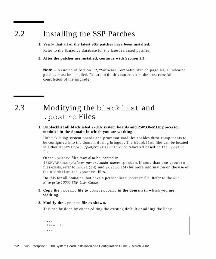
2.2 Installing the SSP Patches1. Verify that all of the latest SSP patches have been installed.
Refer to the SunSolve database for the latest released patches.
2. After the patches are installed, continue with Section 2.3 .
Note – As noted in Section 1.2, “Software Compatibility” on page 1-1, all released
patches must be installed. Failure to do this can result in the unsuccessful
completion of the upgrade.
2.3 Modifying the blacklist and.postrc Files
1. Unblacklist all blacklisted 2760A system boards and 250/336-MHz processormodules in the domain in which you are working.
Unblacklisting system boards and processor modules enables these components to
be configured into the domain during bringup. The blacklist files can be located
in either $SSPVAR/etc/ platform/blacklist or relocated based on the .postrcfile.
Other .postrc files may also be located in
$SSPVAR/etc/ platform_name/ domain_name/.postrc . If more than one .postrcfiles exists, refer to hpost(1M) and postrc (1M) for more information on the use of
the blacklist and .postrc files.
Do this for all domains that have a personalized .postrc file. Refer to the SunEnterprise 10000 SSP User Guide.
2. Copy the .postrc file to .postrc.orig in the domain in which you areworking.
3. Modify the .postrc file as shown.
This can be done by either editing the existing default or adding the lines:
...level 17...
2-2 Sun Enterprise 10000 System Board Installation and Configuration Guide • March 2002

4. After the .postrc files are edited, continue with Section 2.4 .
2.4 Dynamically Reconfiguring the SystemBoards
1. Determine which system boards have alternate paths configured.
See Appendix A for general guidelines. Additionally, consult with the site personnel
to determine Alternate Pathing status and refer to the Sun Enterprise Server AlternatePathing User Guide. If system boards cannot be dynamically reconfigured, see
Section 2.5, “Shutting Down a Domain” on page 2-4.
Note – This procedure is designed to minimize the downtime for a 400-MHz or 466-
MHz upgrade. However, it should be noted that some system boards may not be
detachable due to system configuration.
2. Modify the .postrc file as shown.
This can be done by either editing the existing default or adding the lines:
The skip_phase jtag_integ command is used to allow 400-MHz or 466-MHz
processor modules to be introduced into the system without running autoconfigand rebooting the SSP for each system board.
Caution – Inserting the skip_phase jtag_integ command into the .postrc file
will suppress error messages that would indicate the lack of appropriate post
patches for the 400-MHz or 466-MHz processors. As noted in Section 1.2, “Software
Compatibility” on page 1-1, all released patches must be installed. Failure to do this
can result in the unsuccessful completion of the upgrade.
3. Dynamically reconfigure the system board to be upgraded out of the domain.
Refer to the Sun Enterprise 10000 Dynamic Reconfiguration User Guide.
4. After the system board has been dynamically reconfigured out of the domain,continue with Section 2.6, “Powering Off a System Board” on page 2-5.
...skip_phase jtag_integ...
!
2-3

2.5 Shutting Down a DomainThe following procedure is for halting the operating system on a domain. Do not
perform this procedure if the system boards are dynamically deconfigured from the
domain.
1. Log in to the SSP as user ssp .
2. When prompted for the SUNW_HOSTNAME, use either the platform name or thename of an existing domain.
3. Start a netcon session and log in as root .
4. Notify users that the domain is going down.
5. Halt the domain using the appropriate Solaris commands.
The basic command for halting the system should be shutdown (1M). Refer to the
man page for options and other considerations. For example:
6. Wait for the system-halted message and the OpenBoot PROM (OBP) prompt to bedisplayed on the netcon console window.
7. Repeat Step 1 through Step 6 on each domain that is to be shut down.
8. After the domain is shut down, continue with Section 2.6 .
# cd /# shutdown -i0 -g0 -y
2-4 Sun Enterprise 10000 System Board Installation and Configuration Guide • March 2002
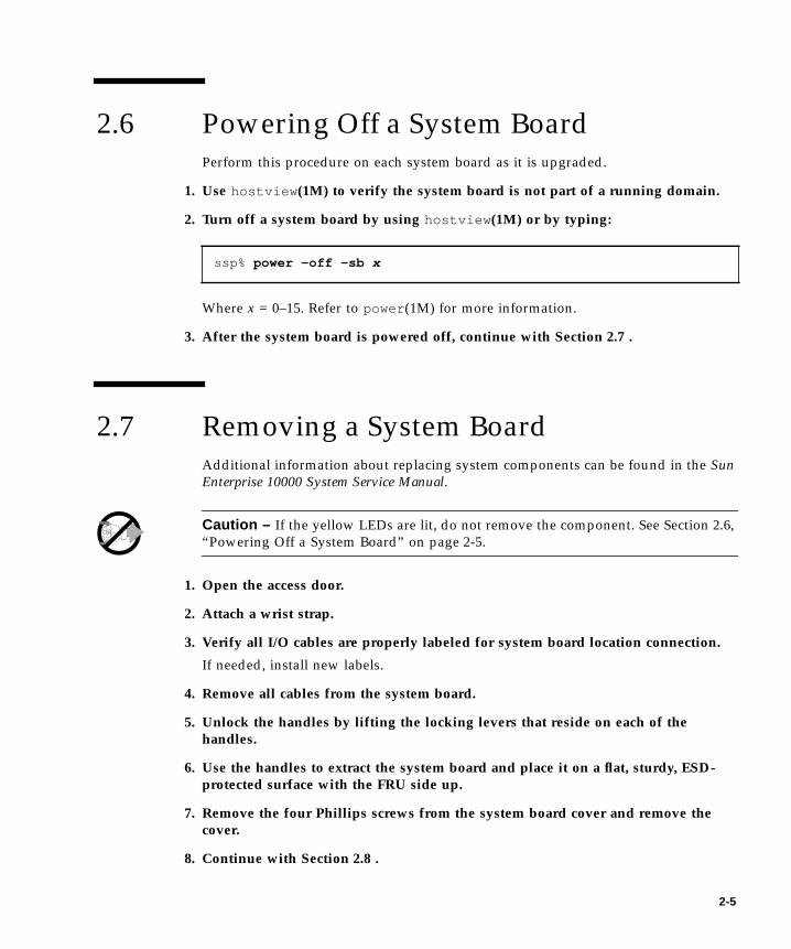
2.6 Powering Off a System BoardPerform this procedure on each system board as it is upgraded.
1. Use hostview (1M) to verify the system board is not part of a running domain.
2. Turn off a system board by using hostview (1M) or by typing:
Where x = 0–15. Refer to power (1M) for more information.
3. After the system board is powered off, continue with Section 2.7 .
2.7 Removing a System BoardAdditional information about replacing system components can be found in the SunEnterprise 10000 System Service Manual.
Caution – If the yellow LEDs are lit, do not remove the component. See Section 2.6,
“Powering Off a System Board” on page 2-5.
1. Open the access door.
2. Attach a wrist strap.
3. Verify all I/O cables are properly labeled for system board location connection.
If needed, install new labels.
4. Remove all cables from the system board.
5. Unlock the handles by lifting the locking levers that reside on each of thehandles.
6. Use the handles to extract the system board and place it on a flat, sturdy, ESD-protected surface with the FRU side up.
7. Remove the four Phillips screws from the system board cover and remove thecover.
8. Continue with Section 2.8 .
ssp% power -off -sb x
2-5

2.8 Configuring System Board ComponentsTo replace a 2760A system board, you transfer all I/O and memory components to
the new 2761A system board. Section 2.8.1 through Section 2.8.3 discusses
configuring mezzanine boards on the system board.
■ If configuring SBus components, see Section 2.8.1, “Replacing the SBus
Component” on page 2-7.
■ If configuring PCI components, see Section 2.8.2, “Replacing the PCI Component”
on page 2-11.
■ If configuring memory components, see Section 2.8.3, “Replacing the Memory
Component” on page 2-17.
Then add the new 400-MHz or 466-MHz processors to the 2761A system board
(Section 2.8.4 ).
After all components have been configured onto the system board, continue with
Section 2.9, “Installing a System Board” on page 2-21.
2-6 Sun Enterprise 10000 System Board Installation and Configuration Guide • March 2002

2.8.1 Replacing the SBus Component
2.8.1.1 Removing the SBus Card and SBus I/O Module
1. Attach a wrist strap and disengage the SBus card by pulling up the handle.
Caution – The connector housing may break if the SBus card is tilted too far.
2. Lift the SBus card from the socket at an angle while guiding the faceplate outfrom the back panel opening.
3. Place the SBus card in an antistatic bag.
4. Remove the five Phillips screws from the I/O module.
5. Loosen the six 3/32-inch captive hex-head screws located on the compressionconnectors.
6. Remove the SBus I/O module.
7. Place the Sbus I/O module on a flat, ESD-protected surface or into an antistaticbag.
2.8.1.2 Installing the SBus I/O Module on the New System Board
1. Attach a wrist strap.
2. On the new system board, prior to installing the module, wipe the gold pads ofthe system board and the exposed contacts of the compression connector with alint-free nonabrasive cloth.
3. Align the SBus I/O module compression connectors to the system boardcompression connector locations.
2-7

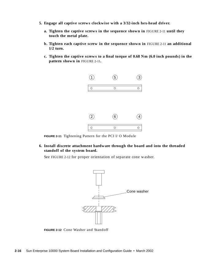
4. Engage all captive screws clockwise with a 3/32-inch hex-head driver.
a. Tighten the captive screws in the sequence shown in FIGURE 2-1 until they touchthe metal plate.
b. Tighten each captive screw in the sequence shown in FIGURE 2-1 an additional1/2 turn.
c. Tighten the captive screws to a final torque of 0.68 Nm (6.0 inch pounds) in thepattern shown in FIGURE 2-1.
FIGURE 2-1 Tightening Pattern for the SBus I/O Module
1 5 3
2 6 4
2-8 Sun Enterprise 10000 System Board Installation and Configuration Guide • March 2002

5. Install discrete attachment hardware through the board and into the threadedstandoff of the system board.
Later versions of the system board include discrete hardware with a captive washer.
If a separate washer is used, see FIGURE 2-2 for proper orientation of cone washer.
FIGURE 2-2 Cone Washer and Standoff
6. Tighten discrete attachment hardware to a torque setting of 0.8 Nm (7.0 inchpounds).
2.8.1.3 Installing the SBus Card
1. Confirm the slot for installing the SBus card.
For maximum I/O performance, avoid populating SBus 0 Slot 0 and SBus 0 Slot 1
together, as well as SBus 1 Slot 0 and SBus 1 Slot 1 together.
2. Attach a wrist strap.
3. If a filler panel covers the desired SBus slot, lift the two tabs and detach the fillerpanel.
4. Remove the SBus card out of the protective packaging.
Inspect the pins in the connector to make sure they are not bent.
5. Guide the SBus card face plate under the springfingers and against the rear face ofthe personality plate.
The I/O connectors of the SBus card should be accessible through the opening in the
personality plate.
6. To align the connector and socket, push the card toward the personality plateagainst the compliant EMI gasket.
Cone washer
2-9

Caution – Do not rock the card onto the socket; the plastic connector housing may
break.
7. Hold the SBus card by the edges near the connector and firmly but gently pressthe card down until the connector is fully seated.
Caution – Make sure filler panels are installed in each vacant slot opening. A
missing filler panel can impair system cooling and FCC regulatory compliance.
8. Confirm that filler panels (part number 340-2305) are installed in all vacant slots.
9. Check for blacklisted components.
If SBus boards have been newly added to a system board, confirm the port
controllers (PCs) on those system boards are not blacklisted. PCs are blacklisted at
the factory when a system board does not have any SBus cards installed.
During the bring-up process, observe the list of blacklisted components.
Alternatively, to retrieve the blacklist file, refer to the blacklist (1M) man page.
Blacklisted PCs need to be unblacklisted prior to creating a domain that would
include those PCs.
In the following example, a domain is to be created using system boards 14 and 15
and the blacklist file is located at $SSPVAR/etc/ platform_name. Each board in this
domain will have an SBus SOC (disk) and HME (network) controller. To see if the
PCs have been blacklisted, type:
To unblacklist the PCs on system boards 14 and 15, edit the
$SSPVAR/etc/platform_name/blacklist file and remove 14.2 and 15.2 from the
pc line.
ssp% more $SSPVAR/etc/ platform_name/blacklistpc 2.2 3.2 5.2 6.2 7.2 10.2 11.2 12.2 13.2 14.2 15.2
2-10 Sun Enterprise 10000 System Board Installation and Configuration Guide • March 2002

2.8.2 Replacing the PCI Component
Before you can install PCI components onto a system board, that board must belong
to a domain that has the Solaris 2.6 or a subsequent compatible operating
environment installed and the SSP must be running version 3.1.1 or a subsequent
compatible version. For information about installing Solaris, refer to documentation
that shipped with the Solaris CD, which contains procedures for installing Solaris 2.6
on a new domain or upgrading a domain to the Solaris 2.6 or a subsequent
compatible operating environment.
The board on which you wish to install the PCI components must also be physically
removed from the system. If the system is up, and the domain to which the board
belongs is running, you must remove the board logically before you do so physically.
The Sun Enterprise 10000 Dynamic Reconfiguration User Guide tells how to do so with
the DR Detach feature.
FIGURE 2-3 PCI Components
2.8.2.1 Preparing the System Boards
1. Attach a wrist strap and loosen the four captive screws on the PCI front cover andremove from the system board front plate (FIGURE 2-4).
PCI card
PCI I/O module
PCI front cover
PCI front
PCI filler panel
System board
Personality
Top PCI riser card
Bottom PCI riser card
bracket
plate
2-11

FIGURE 2-4 PCI Front Cover
2. Remove the PCI retention screw from the top flange of the PCI card, thendisengage the card from the riser card and remove it from the system boardassembly (FIGURE 2-5).
Place the PCI card in an antistatic bag.
FIGURE 2-5 PCI Card
PCI front cover
PCI retention screw
2-12 Sun Enterprise 10000 System Board Installation and Configuration Guide • March 2002
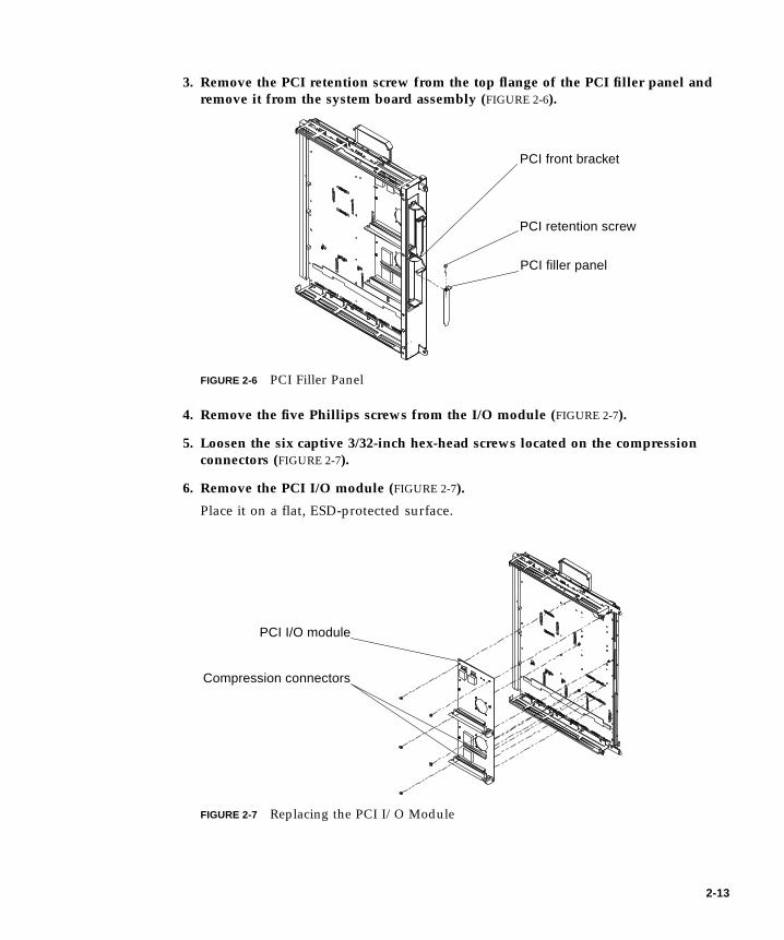
3. Remove the PCI retention screw from the top flange of the PCI filler panel andremove it from the system board assembly (FIGURE 2-6).
FIGURE 2-6 PCI Filler Panel
4. Remove the five Phillips screws from the I/O module (FIGURE 2-7).
5. Loosen the six captive 3/32-inch hex-head screws located on the compressionconnectors (FIGURE 2-7).
6. Remove the PCI I/O module (FIGURE 2-7).
Place it on a flat, ESD-protected surface.
FIGURE 2-7 Replacing the PCI I/O Module
PCI retention screw
PCI filler panel
PCI front bracket
PCI I/O module
Compression connectors
2-13

7. If the new system board is configured for SBus, remove the PCI personality platefrom the old system board.
a. Remove the attachment screws that secure the PCI personality plate(FIGURE 2-8).
Compress the personality plate against the EMI gasket to align the screw holes.
Sustain this force to relieve the stress on the screws threads and remove the three
attachment screws as noted in FIGURE 2-8.
FIGURE 2-8 Removing the Face Plate
b. Locate the angled flanges on the personality plate (FIGURE 2-9).
FIGURE 2-9 Personality Plates
Attachment screws
SBus personality plate PCI personality plate
Angled flanges
2-14 Sun Enterprise 10000 System Board Installation and Configuration Guide • March 2002

c. On the new system board, align the angled flange to the notch of the frontstiffener and swing the personality plate into place against the EMI gasket(FIGURE 2-10).
Do not place the personality plate between the EMI gasket and face plate.
FIGURE 2-10 Installing a Personality Plate—Top View
d. Compress the personality plate against the EMI gasket to align the screw hole.
Sustain this force to relieve the stress on the screws threads and install the three
attachment screws.
2.8.2.2 Installing the PCI Components
1. Attach a wrist strap.
2. Prior to installing the I/O module, wipe the gold pads of the system board and theexposed contacts of the compression connector with a lint-free non-abrasive cloth.
3. Align the PCI I/O module compression connectors to the system boardcompression connector locations.
4. Align the standoffs on the system board with the I/O module.
Personality plate
Front stiffener with notch
Angled flange(s)
EMI gasket
2-15
5. Engage all captive screws clockwise with a 3/32-inch hex-head driver.
a. Tighten the captive screws in the sequence shown in FIGURE 2-11 until theytouch the metal plate.
b. Tighten each captive screw in the sequence shown in FIGURE 2-11 an additional1/2 turn.
c. Tighten the captive screws to a final torque of 0.68 Nm (6.0 inch pounds) in thepattern shown in FIGURE 2-11.
FIGURE 2-11 Tightening Pattern for the PCI I/O Module
6. Install discrete attachment hardware through the board and into the threadedstandoff of the system board.
See FIGURE 2-12 for proper orientation of separate cone washer.
FIGURE 2-12 Cone Washer and Standoff
1 5 3
2 6 4
Cone washer
2-16 Sun Enterprise 10000 System Board Installation and Configuration Guide • March 2002

7. Tighten discrete attachment hardware to a torque setting of 0.7 - 0.8 Nm (6.0 - 7.0inch pounds).
8. Based on the previous configuration, determine the slot for installing the PCI card(FIGURE 2-13).
FIGURE 2-13 PCI Slot Numbering
9. Take the PCI card out of the protective packaging.
Inspect the connector to make sure it is not damaged.
10. Confirm the installed riser card is the correct voltage for the PCI card to beinstalled.
PCI cards and risers cards are available in multiple voltages. Inspect the keyed
connector on the PCI card to confirm that it will properly mate with the riser
connector. If not, obtain and install the correct riser card.
11. Guide the PCI card from behind the system board face plate, through the opening,and place the PCI card edge into the mating connector (FIGURE 2-5).
12. Install the PCI front cover (FIGURE 2-4).
2.8.3 Replacing the Memory Component
1. Attach a wrist strap and remove the eight Phillips screws from the memorymodule.
PCI 0.0
PCI 1.0
2-17

2. Loosen the ten 3/32-inch hex-head captive screws located on the compressionconnector.
3. Lift the memory module straight out and place on a flat, ESD-protected surface.
4. On the new system board, prior to installing the module, wipe the gold pads ofthe system board and the exposed contacts of the compression connector with alint-free non-abrasive cloth.
5. Align the memory module compression connectors to the system boardcompression connectors.
6. Engage all captive connector screws clockwise with a 3/32-inch hex-head driver.
a. Tighten the captive connector screws in the sequence shown in FIGURE 2-14 untilthey touch the metal plate.
b. Tighten each captive connector screw in the sequence shown in FIGURE 2-14 anadditional 1/2 turn.
c. Tighten the captive connector screws to a final torque of 0.68 Nm (6.0 inchpounds) in the pattern shown in FIGURE 2-14.
FIGURE 2-14 Tightening Pattern for the Memory Module
1
5
6
2
9
10
7 3
4 8
2-18 Sun Enterprise 10000 System Board Installation and Configuration Guide • March 2002

7. Install discrete attachment hardware through the cone washer and into the boardand standoff (FIGURE 2-15).
FIGURE 2-15 Cone Washer and Standoff
8. Tighten discrete attachment hardware to a torque setting of 0.8 Nm (7.0 inchpounds).
2.8.4 Replacing the Processor Component
1. Attach a wrist strap and loosen the five 3/32-inch hex-head screws located on thecompression connector.
2. Lift the processor module up and away from obstructions and place it on a flat,ESD-protected surface.
3. Verify the new processor module is 400 MHz or 466 MHz.
4. Verify the new processor module cache size is the same as all other processormodules that are to be installed on the system board.
Mixing cache sizes on a system board will result in the larger caches sizes being
limited to the size of the smallest. If possible, move dissimilar processor modules to
another system board.
5. On the system board, if present, remove the thin blue plastic strip from theprocessor board thermal pad on the system board.
This blue plastic strip covers a white thermal pad that provides thermal relief for the
cache on the processor module. When a processor module is installed, the blue
plastic strip should be removed permanently.
6. Prior to installing the module, wipe the gold pads of the system board and theexposed contacts of the compression connector with a lint-free non-abrasive cloth.
2-19

7. Align processor module compression connectors to the system board compressionconnectors.
8. Engage all captive screws clockwise with a 3/32-inch hex-head driver.
a. Tighten the captive screws in the sequence shown in FIGURE 2-16 until theytouch the metal plate.
b. Tighten each captive screw in the sequence shown in FIGURE 2-16 an additional1/2 turn.
c. Tighten the captive screws to a final torque of 0.68 Nm (6.0 inch pounds) in thepattern shown in FIGURE 2-16.
FIGURE 2-16 Tightening Pattern for the Processor Module
9. Replace the system board cover and secure with four Phillips screws tightening toa torque of 0.8 Nm (7.1 inch pounds).
5
3 1 4
2
3
4
152
2-20 Sun Enterprise 10000 System Board Installation and Configuration Guide • March 2002
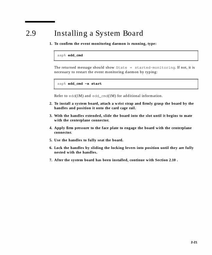
2.9 Installing a System Board1. To confirm the event monitoring daemon is running, type:
The returned message should show State = started-monitoring . If not, it is
necessary to restart the event monitoring daemon by typing:
Refer to edd (1M) and edd_cmd(1M) for additional information.
2. To install a system board, attach a wrist strap and firmly grasp the board by thehandles and position it onto the card cage rail.
3. With the handles extended, slide the board into the slot until it begins to matewith the centerplane connector.
4. Apply firm pressure to the face plate to engage the board with the centerplaneconnector.
5. Use the handles to fully seat the board.
6. Lock the handles by sliding the locking levers into position until they are fullynested with the handles.
7. After the system board has been installed, continue with Section 2.10 .
ssp% edd_cmd
ssp% edd_cmd -x start
2-21

2.10 Powering On a System Board1. Power on a system board by using hostview (1M) or by typing:
Where x = 0–15. Refer to power (1M) for more information.
2. Bring the system board back into the domain.
■ If the domain is still running:
a. If the system board was dynamically deconfigured, reconfigure the board backinto the domain.
Refer to the Sun Enterprise 10000 Dynamic Reconfiguration User Guide.
b. Refer to Section 2.4, “Dynamically Reconfiguring the System Boards” onpage 2-3 for all remaining system boards in the domain.
c. After all of the system boards have been upgraded, and the system is availablefor testing, continue with Chapter 3.
If complete testing and margining is to be deferred until a later time, the domain
can be turned over to the customer using the current system speed.
■ If the domain was shutdown:
a. See Section 2.6, “Powering Off a System Board” on page 2-5 for all remainingsystem boards in the domain.
b. After all of the system boards have been upgraded, continue with Section 2.11 .
ssp% power -on -sb x
2-22 Sun Enterprise 10000 System Board Installation and Configuration Guide • March 2002
2.11 Bringing Up a Domain That Was ShutDown
Note – Do not perform this procedure if the system boards can be dynamically
reconfigured into the domain.
1. Log in to the SSP as ssp .
When prompted for the SUNW_HOSTNAME, use the name of the domain to be started.
2. From the same SSP window, run POST by typing:
Answer y if prompted to configure centerplane. The bringup process can take up to
180 minutes depending on system configuration. Refer to the bringup (1M) or
hpost (1M) man page for more detail.
3. After the domain has been brought up, see Section 2.3, “Modifying the blacklistand .postrc Files” on page 2-2 for all remaining domains.
4. If all domains have been upgraded, and the system is available for testing,continue with Chapter 3.
If complete testing and margining is to be deferred until a later time, the domain can
be turned over to the customer using the current system speed.
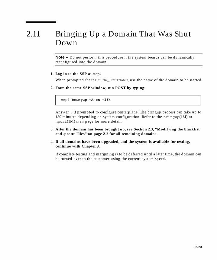
ssp% bringup -A on -l64
2-23

2-24 Sun Enterprise 10000 System Board Installation and Configuration Guide • March 2002

CHAPTER 3
Testing and Certification of theSystem
Prior to testing and certifying the platform, all system boards must be upgraded
with 400-MHz or 466-MHz processors and all system boards must be powered on.
This procedure requires that the system clock be changed and the system boards be
tested on a system-wide level.
Note – This chapter requires all domains to be shut down.
3.1 Shutting Down a Domain1. Log in to the SSP as user ssp .
2. When prompted for the SUNW_HOSTNAME, use either the platform name or thename of an existing domain.
3. Start a netcon session and log in as root .
4. Notify users that the domain is going down.
5. Halt the domain using the appropriate Solaris commands.
The basic command for halting the system should be shutdown (1M). Refer to the
man page for options and other considerations. For example:
# cd /# shutdown -i0 -g0 -y
3-1
6. Wait for the system-halted message and the OBP prompt to be displayed on thenetcon console window.
7. Repeat this procedure for all of the domains in the system.
8. After all domains are shut down, continue with Section 3.2 for a 466-MHzprocessor upgrade, or continue with Section 3.3 for a 400-MHz upgrade.
3.2 Installing a Control Board1. Replace Control Board 0 following the compatibility guidelines in Section 1.3,
“Hardware Compatibility” on page 1-2, and the procedures outlined in the SunEnterprise 10000 System Service Manual.
2. Repeat Step 1 for Control Board 1 (if present).
3. After the control board upgrade is complete, continue with Section 3.3 .
3.3 Modifying the .postrc File1. If the boards were dynamically reconfigured, modify the .postrc file to remove
the skip_phase jtag_integ entry and add a proc_freq_check_percent offentry.:
Do this for all .postrc files that were edited.
The proc_freq_check_percent off command prevents hpost from failing
during Section 3.6, “Testing the System” on page 3-4.
2. Run the autoconfig command on the SSP by typing:
3. Reboot the SSP as suggested by the autoconfig command.
...proc_freq_check_percent off...
ssp% autoconfig
3-2 Sun Enterprise 10000 System Board Installation and Configuration Guide • March 2002

4. After the SSP is rebooted:
■ For a 250/336-MHz to 400MHz upgrade, continue with Section 3.4 .
■ For a 400-MHz to 466-MHz upgrade, continue with Section 3.8, “Setting the Clock
Multiplier and Frequency” on page 3-7 .
3.4 Changing the Clock Multiplier andFrequency for TestingFor testing purposes, this procedures sets the clock to a higher-than-normal speed to
assist with the certification of all components that were introduced into the system.
Caution – Do not run the sys_clock command with any of its command-line
options on a running system. By itself, the sys_clock command provides the
current system clock speed. When options are used in conjunction with the
sys_clock command, modifications are made that can crash a running system.
1. Change the multiplier value by typing:
2. Check the multiplier value by typing:
3. The output should be similar to the following response:
4. After the clock multiplier is set, continue with Section 3.5 .
ssp% sys_clock -p two-to-one -s -i 102000000
ssp% sys_clock
Current Clock Frequencies:--------------------------Interconnect: 102.03 MhzProcessor: 408.20 Mhz
Targeted Clock Frequencies:---------------------------Interconnect: 102.00 MhzProc Clock Ratio: two-to-one
Chapter 3-3

3.5 Bringing Up the Platform for Test andVerification
1. Log in to the SSP as user ssp .
When prompted for the SUNW_HOSTNAME, use the name of the domain to be tested.
2. From the same SSP window, run POST by typing:
Answer y when prompted to configure centerplane. The bringup process can take
up to 180 minutes depending on system configuration. Refer to the bringup (1M) or
hpost (1M) man page for more detail.
3. Repeat Step 1 and Step 2 for all of the domains in the system.
4. After the domain has been brought up, continue with Section 3.6 .
3.6 Testing the SystemSunVTS™ can test the overall functionality of all parts (processor and I/O) of the
system. While an overnight SunVTS run is considered ideal, anywhere between 4 to
24 hours is appropriate as a system test.
It is desirable to test the system under a single domain. However, if this is not
possible, the following steps are required on each domain.
1. Log in to an SSP window as user ssp and type:
2. Start SunVTS by logging in to the domain as root .
ssp% bringup -A off
ssp% domain_switch test_domainssp% xhost +
3-4 Sun Enterprise 10000 System Board Installation and Configuration Guide • March 2002

■ For Solaris 2.5.1:
■ For Solaris 2.6, Solaris 7, and Solaris 8:
If SunVTS fails to initialize, you may need to install the SunVTS packages. See your
Solaris installation instructions and SunVTS AnswerBook2 documentation for more
information.
3. Display the SunVTS window and check the devices shown in the control panelagainst the devices you know to be physically present in the system.
Caution – Be careful to leave unselected, disk devices that may contain customer
data or non-UFS file systems.
Refer to the “control panel” section of the SunVTS documentation if there is a
discrepancy.
Starting SunVTS often serves as a quick check for most hardware devices. If you
have just installed a device and reconfigured your machine accordingly, the SunVTS
test for that device can confirm proper installation.
Likewise, if SunVTS fails to display a device that you know is physically present in
your system, there is a problem, and you should recheck your installation carefully.
4. Set the following options:
■ Threshold Max System Errors = 0
■ Test Execution Max Errors = 0
■ Number of Instances: set to total memory size in GBytes/2 GBytes
■ Set SunVTS options to concentrate on CPU and memory tests
# csh# setenv DISPLAY ssp_hostname:0.0# setenv LD_LIBRARY_PATH /usr/openwin/lib# setenv OPENWINHOME /usr/openwin# /opt/SUNWvts/bin/sunvts -l
# csh# setenv DISPLAY ssp_hostname:0.0# /opt/SUNWvts/bin/sunvts
!
Chapter 3-5

5. Click the Start button.
Or, if you have enabled the Auto Start option from the Set SunVTS Options menu
and saved an options file, you can start SunVTS by typing:
6. Monitor the status of SunVTS. Verify that the system is running and that no testfailures are occurring.
7. If more than one domain exists, repeat Step 2 through Step 6 for each domain tobe tested.
Tests should be run for a minimum of four hours on each domain.
After successful completion of SunVTS, the system is certified for 400-MHz
operation.
8. After the system is tested, continue with Section 3.7 .
3.7 Shutting Down a Domain1. Log in to the SSP as user ssp .
2. When prompted for the SUNW_HOSTNAME, use either the platform name or thename of an existing domain.
3. Start a netcon session and log in as root .
4. Notify users that the domain is going down.
5. Halt the domain using the appropriate Solaris commands.
The basic command for halting the system should be shutdown (1M). Refer to the
man page for options and other considerations. For example:
6. Wait for the system-halted message and the OBP prompt to be displayed on thenetcon console window.
7. Repeat this procedure for all of the domains in the system.
8. After all domains are shut down, continue with Section 3.8 .
# /opt/SUNWvts/bin/sunvts -l -o
# cd /# shutdown -i0 -g0 -y
3-6 Sun Enterprise 10000 System Board Installation and Configuration Guide • March 2002

3.8 Setting the Clock Multiplier andFrequencyThis procedure is done when changing to different speed processor modules. To
upgrade from a lower-speed processor module to a 400-MHz processor module, the
clock multiplier must change to 2:1. To upgrade from a lower-speed processor
module to a 466-MHz processor module, the clock multiplier must change to 5:2. To
do this, all domains must be shut down and the new processors installed onto the
system board.
Caution – Do not run the sys_clock command with any of its command-line
options on a running system. By itself, the sys_clock command provides the
current system clock speed. When options are used in conjunction with the
sys_clock command, modifications are made that can crash a running system.
1. Change the multiplier value by typing:
■ For 400-MHz use the following command:
■ For 466-MHZ use the following command:
This will update the ssp_resource file.
ssp% sys_clock -p two-to-one -s -i 100000000
ssp% sys_clock -p five-to-two -s -i 93000000
Chapter 3-7

2. Check the multiplier value by typing:
■ For 400-MHz the output should be similar to the following response:
■ For 466-MHz the output should be similar to the following response:
3. After the clock multiple is set, continue with Section 3.9 .
ssp% sys_clock
Current Clock Frequencies:--------------------------Interconnect: 99.95 MhzProcessor: 399.85 MhzJTAG: 5.00 Mhz
Targeted Clock Frequencies:---------------------------Interconnect: 100.00 MhzProc Clock Ratio: two-to-oneJTAG: 5.00 Mhz
Current Clock Frequencies:--------------------------Interconnect: 93.25 MhzProcessor: 466.12 MhzJTAG: 5.18 Mhz
Targeted Clock Frequencies:---------------------------Interconnect: 93.00 MhzProc Clock Ratio: five-to-twoJTAG: 5.00 Mhz
3-8 Sun Enterprise 10000 System Board Installation and Configuration Guide • March 2002
3.9 Restoring the hpost Level1. Copy the .postrc.orig file to .postrc .
Do this for all .postrc files that were edited.
2. After the hpost level is restored, see Section 3.10, “Bringing Up a Domain ThatWas Shutdown” on page 3-9.
3.10 Bringing Up a Domain That WasShutdownIf complete testing and margining is to be deferred until a later time, the domain can
be turned over to the customer using the current system speed.
1. Log in to the SSP as ssp .
When prompted for the SUNW_HOSTNAME, use the name of the domain to be started.
2. From the same SSP window, run POST by typing:
Answer y when prompted to configure centerplane. The bringup process can take
up to 180 minutes depending on system configuration. Refer to the bringup (1M) or
hpost (1M) man page for more detail.
3. Repeat Step 1 and Step 2 for all domains in the system.
4. After the upgrade is completed, continue with Chapter 4.
ssp% bringup -A on -l64
Chapter 3-9

3-10 Sun Enterprise 10000 System Board Installation and Configuration Guide • March 2002

CHAPTER 4
Finishing the Installation
4.1 Using the RMA ProcedureReturn the parts in the Sun Enterprise 10000 that are replaced by this upgrade
procedure to Sun Microsystems, Inc. Refer to the Material Return Matrix, located in
the Return Material Authorization(RMA) kit, part number 850-6081 for a list of parts
to be returned.
Note – It is the customer’s responsibility to make sure replaced parts are placed in
ESD approved packaging in a manner that ensures an undamaged and expedient
return.
1. Pack the exchanged returnable parts in appropriate shipping boxes.
2. Label the boxes “Box 1 of n,” “Box 2 of n,” and so forth.
3. Attach the RMA (Return Materials Authorization) label to Box 1 of n. The RMAlabel is located in the RMA kit, part number 850-6081.
4. Ship equipment returns to Sun Microsystems according to the country specificinstructions included in the RMA kit.
4-1

4.2 Post-Installation ChecklistUse the following checklist to confirm the installation is complete.
■ Does the sys_clock command confirm that the system is running at
100/400 MHz for 400-MHz or 93/466 MHz for a 466 MHz system?
■ Did SunVTS complete successfully on all system boards?
■ Have all .postrc files been restored to their original configuration?
■ Are all domains up and running?
■ Has all remaining material been packaged for RMA return?
The system is now upgraded, certified, and ready for use by the customer.
4-2 Sun Enterprise 10000 System Board Installation and Configuration Guide • March 2002

APPENDIX A
Determining DynamicReconfigurability
Consider the following criteria to determine if a system board can be dynamically
reconfigured from a domain.
1. The domains must be running a Solaris 2.6 or a subsequent compatible operating
environment that supports DR and AP, and all operating system patches must be
installed.
2. The SSP must be running SSP 3.1.1 or a subsequent compatible version and all
patches must be installed.
3. AP 2.1 or subsequent compatible version must be used.
4. All DR patches must be installed.
5. All I/O devices must be under AP control or the system can continue to operate
with the non-AP devices offline.
6. Alternate paths must be physically located on a different system board.
7. The system boot and console network and other I/O devices have AP applied
and are DR safe.
If an Oracle, Sybase, or Informix database is in use, and in Intimate Shared Memory
(ISM) mode, memory is required to be at least 50% free to start the upgrade. Confirm
the memory usage with the vmstat command.
A-1

A-2 Sun Enterprise 10000 System Board Installation and Configuration Guide • March 2002

Index
SYMBOLS.postrc , 2-2, 3-2, 3-9
NUMERICS2760A system board, 1-2
2761A system board, 1-2
AAfter all components have been configured, 2-6
After the .postrc files are edited, 2-3
After the patches are installed, 2-2
After the SSP is upgraded, 2-1
After the system board has been installed, 2-21
After the system board is reconfigured, 2-3
After the system board is shut off, 2-5
Bblacklist, 2-2, 2-10
Cchecklist
post-installation, 4-2
clock multiplier
operating frequency, 3-7
testing frequency, 3-3
compatibility
hardware, 1-2
software, 1-1, A-1
Ddynamic reconfiguration, 2-3, 2-22, A-1
Ffiller panel
SBus card, 2-9
frequency
operating, 3-7
testing, 3-3
Hhardware compatibility, 1-2
hpost , 2-2, 3-9
Iinstalling
memory module, 2-18
PCI components, 2-11
PCI I/O module, 2-15
processor module, 2-19
SBus card, 2-9
SBus I/O module, 2-7
system board, 2-21
-1

Mmemory module
installing, 2-18
removing, 2-17
replacement, 2-17
Ooperating frequency, 3-7
PPCI components
installing, 2-11
PCI I/O module
installing, 2-15
removing, 2-13
replacement, 2-13
post-installation checklist, 4-2
powering off
system board, 2-5
powering off the system,, 2-4, 3-1, 3-6
powering on
system board, 2-22
process overview, 1-1
processor module
installing, 2-19
replacement, 2-19
Rremoving
memory module, 2-17
PCI I/O module, 2-13
SBus card, 2-7
SBus card filler panel, 2-9
SBus I/O module, 2-7
system board, 2-5
replacement
memory module, 2-17
PCI I/O module, 2-13
processor module, 2-19
SBus card, 2-7
SBus I/O module, 2-7
return materials authorization, 4-1
RMA, 4-1
SSBus card
filler panel, 2-9
installing, 2-9
removing, 2-7
replacement, 2-7
SBus I/O module
installing, 2-7
removing, 2-7
replacement, 2-7
software compatibility, 1-1, A-1
sys_clock , 3-3, 3-7
system board
2760A, 1-2
2761A, 1-2
installing, 2-21
powering off, 2-5
powering on, 2-22
removing, 2-5
Ttesting frequency, 3-3
tools required, 1-1
Uupgrade procedure, 2-1
-2 Sun Enterprise 10000 System Board Installation and Configuration Guide • March 2002