sun earth connection coronal and heliospheric investigation (secchi) · 68 r.a. howard et al....
TRANSCRIPT

Space Sci Rev (2008) 136: 67–115DOI 10.1007/s11214-008-9341-4
Sun Earth Connection Coronal and HeliosphericInvestigation (SECCHI)
R.A. Howard · J.D. Moses · A. Vourlidas · J.S. Newmark · D.G. Socker ·S.P. Plunkett · C.M. Korendyke · J.W. Cook · A. Hurley · J.M. Davila ·W.T. Thompson · O.C. St Cyr · E. Mentzell · K. Mehalick · J.R. Lemen ·J.P. Wuelser · D.W. Duncan · T.D. Tarbell · C.J. Wolfson · A. Moore · R.A. Harrison ·N.R. Waltham · J. Lang · C.J. Davis · C.J. Eyles · H. Mapson-Menard ·G.M. Simnett · J.P. Halain · J.M. Defise · E. Mazy · P. Rochus · R. Mercier ·M.F. Ravet · F. Delmotte · F. Auchere · J.P. Delaboudiniere · V. Bothmer ·W. Deutsch · D. Wang · N. Rich · S. Cooper · V. Stephens · G. Maahs · R. Baugh ·D. McMullin · T. Carter
Received: 30 November 2006 / Accepted: 12 March 2008 / Published online: 16 May 2008© Springer Science+Business Media B.V. 2008
R.A. Howard (�) · J.D. Moses · A. Vourlidas · J.S. Newmark · D.G. Socker · S.P. Plunkett ·C.M. Korendyke · J.W. Cook · A. HurleyE.O. Hulburt Center for Space Research, Naval Research Laboratory, Washington, DC 20375, USAe-mail: [email protected]
J.M. Davila · W.T. Thompson · O.C. St Cyr · E. Mentzell · K. MehalickNASA Goddard Space Flight Center, Greenbelt, MD 20742, USA
J.R. Lemen · J.P. Wuelser · D.W. Duncan · T.D. Tarbell · C.J. Wolfson · A. MooreLockheed Martin Solar and Astrophysics Lab., Palo Alto, CA 94304, USA
R.A. Harrison · N.R. Waltham · J. Lang · C.J. DavisSpace Science and Technology Dept., Rutherford Appleton Laboratory, Chilton, Didcot,Oxfordshire OX11 OQX, UK
C.J. Eyles · H. Mapson-Menard · G.M. SimnettAstrophysics and Space Research Group, University of Birmingham, Edgbaston, Birmingham B15 2TT,UK
J.P. Halain · J.M. Defise · E. Mazy · P. RochusCentre Spatiale de Liège, Université de Liège, Avenue du Pré-Aily, 4031 Angleur, Belgium
R. Mercier · M.F. Ravet · F. DelmotteLaboratoire Charles-Fabry de l’Institut d’Optique (IOTA), Campus Polytechnique, RD 128-91227,Palaiseau Cedex, France
F. Auchere · J.P. DelaboudiniereInstitut d’Astrophysique Spatiale, Centre universitaire d’Orsay, Bât 120-121, 91405 Orsay Cedex,France
V. BothmerMax-Planck-Institute for Solar System Research, Institute for Astrophysics, University of Göttingen,37077 Göttingen, Germany

68 R.A. Howard et al.
Abstract The Sun Earth Connection Coronal and Heliospheric Investigation (SECCHI) is afive telescope package, which has been developed for the Solar Terrestrial Relation Observa-tory (STEREO) mission by the Naval Research Laboratory (USA), the Lockheed Solar andAstrophysics Laboratory (USA), the Goddard Space Flight Center (USA), the Universityof Birmingham (UK), the Rutherford Appleton Laboratory (UK), the Max Planck Institutefor Solar System Research (Germany), the Centre Spatiale de Leige (Belgium), the Insti-tut d’Optique (France) and the Institut d’Astrophysique Spatiale (France). SECCHI com-prises five telescopes, which together image the solar corona from the solar disk to beyond1 AU. These telescopes are: an extreme ultraviolet imager (EUVI: 1–1.7 R�), two tradi-tional Lyot coronagraphs (COR1: 1.5–4 R� and COR2: 2.5–15 R�) and two new designsof heliospheric imagers (HI-1: 15–84 R� and HI-2: 66–318 R�). All the instruments use2048 × 2048 pixel CCD arrays in a backside-in mode. The EUVI backside surface has beenspecially processed for EUV sensitivity, while the others have an anti-reflection coating ap-plied. A multi-tasking operating system, running on a PowerPC CPU, receives commandsfrom the spacecraft, controls the instrument operations, acquires the images and compressesthem for downlink through the main science channel (at compression factors typically up to20×) and also through a low bandwidth channel to be used for space weather forecasting(at compression factors up to 200×). An image compression factor of about 10× enable thecollection of images at the rate of about one every 2–3 minutes. Identical instruments, exceptfor different sizes of occulters, are included on the STEREO-A and STEREO-B spacecraft.
Keywords Solar corona · Lyot coronagraph · XUV heliograph · Heliospheric imager ·Coronal loops · Coronal mass ejections · Stereo · Heliosphere
1 Introduction
The Sun-Earth-Connection Coronal and Heliospheric Investigation (SECCHI; see Howardet al. 2000) for the NASA Solar Terrestrial Relations Observatory (STEREO) mission is asuite of optical telescopes that will, for the first time, observe the entire inner heliospherefrom the solar surface out to the vicinity of Earth. By combining this very large field ofview with the radio and in-situ measurements from STEREO as well as from other space-and earth-based assets, we expect to answer some important questions of the physics ofCoronal Mass Ejections (CMEs). The instrument acronym is also a reference to AngeloSecchi (1818–1878) a pioneering Italian astrophysicist who was one of the first to apply thenew technology of photography to recording eclipses. In a similar way we anticipate thatSECCHI will provide pioneering observations of CMEs as well as other structures, such asloops, plumes, streamers, comets, etc., using stereo reconstruction techniques.
W. DeutschMax-Planck-Institut for Solar System Research, Katlenburg-Lindau, Germany
D. Wang · N. RichInterferometrics, Inc., 13454 Sunrise Valley Drive, Herndon, VA 20171, USA
S. Cooper · V. Stephens · G. MaahsHYTEC Inc., 110 Eastgate Drive, Los Alamos, NM 87544, USA
R. Baugh · D. McMullin · T. CarterPraxis, Inc., 2550 Huntington Ave. Suite 300, Alexandria, VA 22303, USA
Sun Earth Connection Coronal and Heliospheric Investigation 69
The primary objective of the STEREO mission is to understand the CME phenomenon,a phenomenon that was discovered in 1971 and has been observed by coronagraphic in-struments on five missions, most recently the ESA/NASA Solar and Heliospheric Mission(SOHO) (see Howard 2006 and references therein). But, this is the first mission whose pri-mary objective is to elucidate the CME itself. The primary objectives of SECCHI are:
• What is the timing of physical properties involved in CME initiation? What are the struc-tures involved in the CME initiation?
• What is the 3-dimensional structure and kinematic properties of CMEs?• What is the 3-dimensional structure of active regions, coronal loops, helmet streamers,
etc.?• What are the critical forces controlling the propagation of CMEs in the corona and inter-
planetary medium?
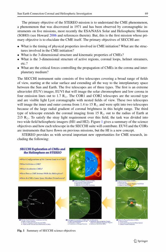
The SECCHI instrument suite consists of five telescopes covering a broad range of fieldsof view, starting at the solar surface and extending all the way to the interplanetary spacebetween the Sun and Earth. The five telescopes are of three types. The first is an extremeultraviolet (EUV) imager, EUVI that will image the solar chromosphere and low corona infour emission lines out to 1.7 R�. The COR1 and COR2 telescopes are the second typeand are visible light Lyot coronagraphs with nested fields of view. These two telescopeswill image the inner and outer corona from 1.4 to 15 R� and were split into two telescopesbecause of the large radial gradient of coronal brightness in this height range. The thirdtype of telescope extends the coronal imaging from 15 R� out to the radius of Earth at215 R�. To satisfy the stray light requirement over this field, the task was divided intotwo wide field heliospheric imagers (HI1 and HI2). Figure 1 gives a summary of the scienceobjectives and how each telescope in the SECCHI suite will contribute. EUVI and the CORsare instruments that have flown on previous missions, but the HI is a new concept.
STEREO provides us with several important new opportunities for CME research, in-cluding the following:
Fig. 1 Summary of SECCHI science objectives
70 R.A. Howard et al.
• The first opportunity to obtain stereographic views of CMEs;• The first opportunity to observe a CME in interplanetary space at the same time that in-
situ measurements are made;• The first opportunity to make simultaneous optical and radio observations of CMEs and
shocks;• The first opportunity to observe geo-effective CMEs along the Sun-Earth line in inter-
planetary space;• The first opportunity to detect CMEs in a field of view that includes the Earth.
In this paper we present an overview of the SECCHI instrument—the five main telescopes,the guide telescope (GT), the optical bench for the sun-pointed instruments, the mechanisms,the SECCHI electronics, the CCD detector, housing and control electronics, the flight soft-ware and the concept of operations. The hardware is assembled into three packages: (1) theSun-Centered-Instrument Package (SCIP) which has the EUVI, COR1, COR2, GT and theSCIP camera electronics box (CEB), (2) the Heliospheric Imager (HI), which contains boththe HI-1 and HI-2 and the HI-CEB, and (3) the SECCHI electronics box (SEB). The SCIPis located within the spacecraft cylinder at the center of the spacecraft; the HI is located onthe earthward-pointing spacecraft face and the SEB is located within the spacecraft.
2 Extreme UltraViolet Imager (EUVI)
2.1 EUVI Telescope Overview
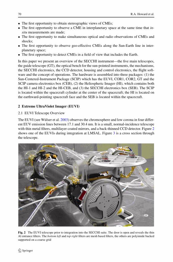
The EUVI (see Wülser et al. 2003) observes the chromosphere and low corona in four differ-ent EUV emission lines between 17.1 and 30.4 nm. It is a small, normal-incidence telescopewith thin metal filters, multilayer coated mirrors, and a back-thinned CCD detector. Figure 2shows one of the EUVIs during integration at LMSAL. Figure 3 is a cross section throughthe telescope.
Fig. 2 The EUVI telescope prior to integration into the SECCHI suite. The door is open and reveals the thinAl entrance filters. The bottom left and top right filters are mesh based filters, the others are polyimide backedsupported on a coarse grid

Sun Earth Connection Coronal and Heliospheric Investigation 71
Fig. 3 EUVI telescope cross section
Table 1 EUVI telescope properties
Instrument type Normal incidence EUV telescope (Ritchey-Chrétien)
Wavelengths He II 30.4 nm, Fe IX 17.1 nm, Fe XII 19.5 nm, Fe XV 28.4 nm
IR/visible/UV rejection >1013 using thin metal film filters
Aperture 98 mm at primary mirror
Effective focal length 1750 mm
Field of view Circular full sun field of view to ±1.7 solar radii
Spatial scale 1.6′′ pixels
Detector Backside illuminated CCD (e2v CCD42-40), 2048 × 2048 pixels
Mechanisms Aperture door, Quadrant selector, Filter wheel, Focal plane shutter
Image Stabilization Active secondary mirror (tip/tilt)
Range: ±7′′, jitter attenuation: factor 3 at 10 Hz
EUV radiation enters the telescope through a thin metal film filter of 150 nm of alu-minum. This filter suppresses most of the UV, visible, and IR radiation and keeps the solarheat out of the telescope. During launch, the filter is protected by the front door. The radi-ation then passes through the quadrant selector to one of the four quadrants of the optics.Each quadrant of the primary and secondary mirror is coated with a narrow-band, multilayerreflective coating, optimized for one of four EUV lines. After bouncing off the primary andsecondary mirror, the radiation continues through a filter wheel that has redundant thin-filmaluminum filters to remove the remainder of the visible and IR radiation. A rotating bladeshutter controls the exposure time. The image is formed on a CCD detector. The main para-meters for the EUVI telescope are summarized in Table 1.
2.2 Optics
2.2.1 Optical Design
The EUVI telescope is a Ritchey-Chrétien system with a secondary mirror magnificationof 2.42. This system provides pixel limited resolution across the entire field of view in allfour quadrants. The low secondary mirror magnification reduces the telescope’s sensitivityto shifts in the mirror separation and eliminates the need for a focus mechanism. The tele-scope is fully baffled to prevent charged particles entering the front aperture from reachingthe CCD. The telescope pupil is located just in front of the primary mirror and is definedby an aperture mask. The baffles and aperture mask have been designed for an unvignetted

72 R.A. Howard et al.
Fig. 4 Ray trace results for a single quadrant and two field angles (0 and 27 arcmin) at nominal focus, andup to 150 µm inside (−150) and outside (150) of nominal focus. The boxes indicate the size of one CCDpixel
Table 2 Properties of the multilayer coatings
Quadrant/channel 17.1 19.5 28.4 30.4
Center wavelength (two mirror system) 17.3 nm 19.6 nm 28.5 nm 30.7 nm
Bandwidth 1.4 nm 1.6 nm 1.9 nm 3.0 nm
(measured FWHM for single reflection)
Peak reflectivity 39% 35% 15% 23%
(measured, for single reflection)
Coating materials MoSi MoSi MoSi, var. spacing MoSi
field of view to ±1.7 solar radii. Figure 4 shows ray trace results for a single quadrant, bothon-axis and at the edge of the field, and up to 0.15 mm inside and outside of nominal focus.The system has a minor amount of field curvature; the nominal focus location is chosen tominimize the aberrations across the field.
2.2.2 Mirrors
The EUVI mirrors were figured, polished, and multilayer coated at the Institut d’Optique inOrsay, who also made the mirrors for SOHO/EIT. The Zerodur mirror substrates were firstpolished to a sphere and superpolished to the required surface roughness. They were thenaspherized using an ion beam etching technique that preserves the superpolished propertiesof the surface. Finally, each quadrant of each mirror was coated with a narrow passbandreflective multilayer, optimized for the specific EUV emission to be observed in that quad-rant. All coatings consist of MoSi layer pairs using constant layer spacing. The coating forthe 28.4 nm quadrant has a variable Mo/Si thickness ratio for optimum suppression of thenearby 30.4 nm He II emission line. The other coatings use constant layer spacings. Table 2summarizes the properties of the coatings (Ravet et al. 2003).

Sun Earth Connection Coronal and Heliospheric Investigation 73
2.2.3 Filters
The EUVI uses thin metal film filters at both the entrance aperture and near the focal planeto suppress undesired UV, visible, and IR radiation. Two types of filters are at the entranceof the telescope (Fig. 2): an aluminum-on-polyimide foil on a coarse nickel grid for theshort wavelength quadrants (17.1 and 19.5 nm), and a single layer aluminum foil on a finenickel mesh for the long wavelength quadrants (28.4 and 30.4 nm). Both types of filtersuse a 150 nm thick layer of aluminum to reject visible light. The grid-supported aluminumfilter is backed with a 70 nm thick layer of polyimide for strength. The polyimide layerallows the filter to be supported by a coarse grid with 5 mm line spacing that causes onlyminimal diffraction at EUV wavelengths. The polyimide transmits only about 50% of theEUV radiation at the observing wavelengths, but this is not a major concern for the stronglines at 17.1 and 19.5 nm.
The mesh supported filter avoids the absorbing polyimide layer, whose transmission istoo low at longer wavelengths, especially for the somewhat weaker line at 28.4 nm. How-ever, the fine mesh, with 0.36 mm line spacing, causes a noticeable amount of diffraction.Both types of filters have been flown on highly successful experiments: EIT used a plasticreinforced aluminum foil on a nearly identical coarse grid for all wavelengths and TRACE(Handy et al. 1999; Strong et al. 1994) used fine mesh supported filters nearly identical tothe ones on the EUVI.
Near the focal plane, a final filter reduces the visible light transmitted by the first filterand by any pinholes that form in the front filter. This final filter is in a filter wheel with fourpositions, to provide additional protection against pinholes. A third filter wheel positioncontains two filters in series to mitigate against any catastrophic damage to the entrancefilters. The fourth filter slot is left open, which enabled visible light testing on the ground.All filters were manufactured by LUXEL Corporation.
2.2.4 Aliveness Source
The EUVI telescope contains blue and violet light emitting diodes (LEDs) for testing andcalibration purposes. One set of LEDs is mounted in the spider and illuminates the detectorthrough reflection off the two telescope mirrors. A second set is mounted near the CCD.Photons from the blue LED at 470 nm have a similar penetration depth in silicon as EUVphotons, while photons from the violet LED at 400 nm, which have a shallower penetrationdepth, provide a diagnostic that is sensitive to CCD surface effects.
2.3 Mechanical Design
2.3.1 Metering Structure
The EUVI uses a Graphite/Cyanate Ester metering tube as the main telescope structure.The tube stiffness maintains proper alignment of the optical system through launch. Thelow coefficient of thermal expansion (CTE) in the axial direction minimizes changes in themirror separation and keeps the telescope in focus throughout the operational temperaturerange. This eliminates the need for a focus mechanism. The metering tube is lined with analuminum foil on the inside that acts as a vapor and contamination barrier.
Attached to the front of the metering tube are the secondary mirror spider, the quadrantselector spider, and the entrance chamber with the entrance filters and the interfaces to theaperture door and the forward mount. The spider arms are hollow and incorporate separatevent paths for the secondary mirror tip-tilt mechanism and for the quadrant selector motor.

74 R.A. Howard et al.
Fig. 5 Left—EUVI primary mirror, coated and mounted. The mirror diameter is 105 mm. The regions be-tween the quadrants are deliberately left uncoated. Right—EUVI secondary mirror and tip-tilt mechanism.The mirror diameter is 48 mm. One of the three PZTs (marked “L2. . . M”) is visible inside the housing
Attached to the aft end of the metering tube are the primary mirror mount and the aft me-tering structure with the shutter and filter wheel mechanisms, as well as the interfaces to thefocal plane assembly and the aft mounts. The aft structure again incorporates separate ventpaths for its mechanisms to minimize potential sources of contaminants inside the opticalcavity.
2.3.2 Mirror Mounts
The EUVI primary mirror and mount are shown in Fig. 5. The mount consists of a hexag-onal Titanium ring that interfaces to the mirror substrate via three bi-pod flexures. Thisarrangement is semi-kinematic: each bi-pod strongly constrains two degrees of freedom, butis relatively flexible in the other four, thus isolating the mirror from thermal stresses in themount. Interferometric tests showed that temperature changes of up to 22◦C cause no mea-surable deformation of the mirror figure. The bi-pods are made of Invar and attach to theZerodur mirror through bonded Invar mounting pads. This mirror mount is very compact tofit the tight envelope constraints of the EUVI telescope.
The secondary mirror mount with its tip-tilt mechanism is shown in Fig. 5. The mount isa single piece of Invar with three machined fingers that are bonded to the cylindrical base ofthe Zerodur mirror substrate. The tip-tilt mechanism is very similar to the one on the TRACEtelescope. It uses three piezoelectric (PZT) actuators that push against the Invar mount ofthe mirror. Software in the SECCHI flight electronics processes fine pointing signals fromthe SECCHI guide telescope and drives the PZT actuators open loop via a simple digital-to-analog converter and low voltage drivers. The tip-tilt range in the EUVI image space is±7 arcseconds, sufficient to accommodate worst case spacecraft jitter.
2.4 Instrument Response and Calibration
2.4.1 Calibration Results
The EUVI mirrors were calibrated as pairs at the synchrotron of the Institut d’AstrophysiqueSpatiale in Orsay. The mirrors were arranged in the same geometry as in the EUVI telescope,
Sun Earth Connection Coronal and Heliospheric Investigation 75
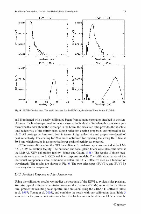
Fig. 6 EUVI effective area. The solid lines are for the EUVI-A, the dashed lines for the EUVI-B
and illuminated with a nearly collimated beam from a monochromator attached to the syn-chrotron. Each telescope quadrant was measured individually. Wavelength scans were per-formed with and without the telescope in the beam; the measured ratio provides the absolutetotal reflectivity of the mirror pairs. Single reflection coating properties are reported in Ta-ble 2. All coatings perform well, both in terms of high reflectivity and proper wavelength ofpeak reflectivity. The coating for 28.4 nm is optimized for rejecting the strong He II line at30.4 nm, which results in a somewhat lower peak reflectivity as expected.
CCDs were calibrated on the NRL beamline at Brookhaven synchrotron and at the LM-SAL XUV calibration facility. The entrance and focal plane filters were also calibrated atthe LMSAL XUV calibration facility (Windt and Catura 1988). The results of those mea-surements were used to fit CCD and filter response models. The calibration curves of theindividual components were combined to obtain the EUVI effective area as a function ofwavelength. The results are shown in Fig. 6. The two telescopes (EUVI-A and EUVI-B)have very similar responses.
2.4.2 Predicted Response to Solar Phenomena
Using the calibration results we predict the response of the EUVI to typical solar plasmas.We take typical differential emission measure distributions (DEMs) reported in the litera-ture, predict the resulting solar spectral line emission using the CHIANTI software (Dereet al. 1997; Young et al. 2003), and combine the result with our calibration data. Table 3summarizes the pixel count rates for selected solar features in the different EUVI channels.

76 R.A. Howard et al.
Table 3 Photon count rates (photons/pixel/second) for some solar features predicted with the CHIANTIcode. The numbers for the 30.4 nm channel have been tripled to adjust for the fact that CHIANTI typicallyunderestimates the He II flux. The first number in each box is for the EUVI-A, the second for the EUVI-B
Photons/s/pixel Quiet Sun Active region M class flare
17.1 nm 92/98 954/976 25700/26700
19.5 nm 40/41 784/792 92200/101500
28.4 nm 4/4 118/130 5540/6110
30.4 nm 30/30 428/419 18100/17800
Fig. 7 The response of the EUVI as a function of solar plasma temperature. The solid lines are for theEUVI-A, the dashed lines for the EUVI-B
Note that CHIANTI underestimates the He II flux by typically a factor of three so we havemultiplied the prediction by a factor of 3. Figure 7 shows count rates (in photons/pixel/s)predicted for isothermal plasmas (for an EM of 1011 cm−5) as a function of plasma temper-ature.
3 Inner Coronagraph (COR1)
3.1 COR1 Overview
Like all coronagraphs, COR1 is designed to measure the weak light from the solar coronain the presence of scattered light from the much brighter solar photosphere. It is a classic
Sun Earth Connection Coronal and Heliospheric Investigation 77
Lyot internally occulting refractive coronagraph (Lyot 1939) which will observe the whitelight corona from 1.4 to 4 R�. The COR1 design is the first space-borne internally occultedrefractive coronagraph in contrast to the LASCO/C1 (Brueckner et al. 1995), which wasan internally occulted reflective design. The optical design, described in the next section,uses the principles articulated by Lyot to eliminate some of the sources of stray light. Theinternal occultation enables better spatial resolution closer to the limb than an externallyocculted design.
The COR1 signal will be dominated by instrumentally scattered light, which must beremoved to measure the underlying coronal signal. This stray light cannot be removed bythe Lyot principles but is largely unpolarized and therefore can be eliminated or at leastgreatly reduced by making polarized observations in three states of linear polarization andcalculating the polarized brightness (pB). To achieve this separation, we must have a highenough signal to noise ratio, even in the presence of the large scattered light noise. This ispartly achieved by performing on-board binning of the pixels.
3.2 Optical Layout
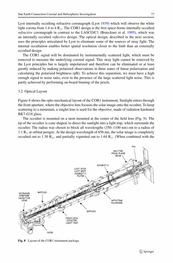
Figure 8 shows the opto-mechanical layout of the COR1 instrument. Sunlight enters throughthe front aperture, where the objective lens focuses the solar image onto the occulter. To keepscattering to a minimum, a singlet lens is used for the objective, made of radiation hardenedBK7-G18 glass.
The occulter is mounted on a stem mounted at the center of the field lens (Fig. 9). Thetip of the occulter is cone shaped, to direct the sunlight into a light trap, which surrounds theocculter. The radius was chosen to block all wavelengths (350–1100 nm) out to a radius of1.1 R� at orbital perigee. At the design wavelength of 656 nm, the solar image is completelyocculted out to 1.30 R�, and partially vignetted out to 1.64 R�. (When combined with the
Fig. 8 Layout of the COR1 instrument package

78 R.A. Howard et al.
Fig. 9 The conical occulter mounted at the center of the field lens, and surrounded by the light trap. Hashedregions show the presence of material at the central plane in this cutaway view
focal plane mask discussed below, these numbers become 1.4 and 1.9 R� respectively.) Thewedge-shaped design of the light trap ensures that any ray entering it must reflect manytimes, so that the light will be absorbed before it can find its way out again.
Two doublet lenses are used to focus the coronal image onto the CCD detector. The first,a positive power achromat, is placed immediately behind the Lyot stop, while the second,a negative power achromat, is placed further down the optical path. Together, these act as atelephoto-lens system, focusing the coronal image onto the detector plane, while maintain-ing diffraction-limited resolution. A bandpass filter 22.5 nm wide, centered on the Hα lineat 656 nm, is placed just behind the first doublet. Thus, the Lyot stop, spot, first doublet, andbandpass filter form a single optical assembly.
A linear polarizer on a hollow core motor rotational stage is located between the twodoublets. The polarizing material is Corning’s Polarcor, chosen for its uniformity. The place-ment of the polarizer was chosen to be as close to the first doublet as possible within thedimension constraints of the largest diameter piece of Polarcor that can be obtained (33 mmclear aperture). Normal operations call for three sequential images to be taken with polar-izations of 0 degrees and ±60 degrees, to extract the polarized brightness.
3.3 Stray Light Suppression
The primary photospheric light suppression mechanisms in COR1 are those described byLyot (1939)—(1) the objective lens to occulter imaging system, (2) the aperture stop tofield lens to Lyot stop imaging system and (3) a Lyot spot. A final stray light suppressiontechnique is the inclusion of a focal plane mask.
The singlet objective lens only focuses the solar image accurately at a single wavelength.Thus only a single wavelength of the photosphere is blocked by the internal occulter. A nar-row band filter defines the passband of the instrument, which matches the wavelength atthe primary focus of the objective lens. Rather than relying on the out-of-band rejection of

Sun Earth Connection Coronal and Heliospheric Investigation 79
the filter, the primary suppression mechanisms are designed to work over the full sensitivitywavelength band of the instrument.
The solar image from the objective will be chromatically aberrated, so the occultermust be sized to block all the solar photospheric light from the near UV to infrared (350–1100 nm). The cut-on at 350 nm is set by the transmission of the BK7-G18 glass in theobjective lens, and the cut-off at 1100 nm is set by the band gap of the silicon detector. Sub-sequent lenses in the optical train balance the chromatic aberration from the objective. Thenarrow bandpass of the instrument also minimizes the effect of chromatic aberration in thefinal image.
Diffracted light from the edge of the front entrance aperture is focused onto a Lyot stopby the field lens and removed. This eliminates the largest source of stray light in the system.Additional stray light rejection is accomplished by placing baffles at various points betweenthe front aperture and Lyot stop. A Lyot spot is also glued to the front surface of the doubletlens immediately behind the Lyot stop, to remove ghosting from the objective lens.
A focal plane mask is located between the shutter and the focal plane detector, and is usedto remove diffracted light from the edge of the occulter. This circular mask, mounted on aplane of BK7 glass, is sized to be slightly larger than the occulter image at that location.Without the mask, the image on the detector would be dominated by bright rings at theumbral and penumbral edges of the occulter shadow. The addition of the focal plane maskremoves these bright rings. The focal plane assembly is discussed in Sect. 9.
3.4 Mechanical and Thermal Design
The COR1 mechanical structure is designed as a series of tube sections (Fig. 8), which arebolted and pinned together for stability. The individual optics are aligned, mounted, andpinned within these tube sections. COR1 assembly starts from the front tube section, withthe objective, occulter, light trap, and field lens, and then each subsequent section is added,together with its associated optical or mechanical components. Because the individual tubesections are pinned together, sections can be taken off and back on again without changingthe optical alignment.
Three mechanisms are included in the COR1 instrument package. At the front of the in-strument is a door, to protect the instrument before and during launch, and during spacecraftmaneuvers. On the front of this door is a diffuser so that the operation of the instrument canbe tested when the door is closed, and to provide a flat-field calibration signal. The diffuseris sized to completely illuminate the objective over all angles within the field-of-view.
The other two mechanisms are the hollow core motor to rotate the linear polarizer, and arotating blade shutter mounted just in front of the focal plane detector assembly, both sup-plied by Lockheed Martin. All the mechanisms, together with the focal plane CCD detector,will be operated from a centralized control system for all the SECCHI instruments.
Because the two STEREO spacecraft are in elliptical orbits about the Sun, the COR1 in-struments will experience considerable variation in solar load, from 1264–1769 and 1068–1482 W/m2 for the Ahead and Behind spacecraft respectively. When these loads are com-bined with the modeled changes in the material thermal properties from beginning to endof life, and with the most extreme differences in the thermal loads from the surroundingstructure, the worst-case temperature variation in the COR1 instrument is from 2.5 to 30◦C.There’s also an axial gradient in temperature from the front to the back of the instrument,varying from 3◦C in the cold case, to 7◦C in the hot case. Strategically placed software con-trolled proportional heaters with programmable set points, are used to keep the instrument

80 R.A. Howard et al.
within the 0–40◦C operational temperature range. There are also survival heaters on me-chanical thermostat control to keep the instrument within the −20 to +55◦C non-operationalrange.
Specialized composite coatings of oxides over silver are used to help manage the intensesolar fluxes which COR1 will be experiencing. The oxide coatings are deposited onto manyof the exposed surfaces around the aperture area, such as the objective lens holder assemblyand door assemblies. This coating exhibits very low solar absorbtivities, is very stable, andhas relatively high IR emissivity values depending on the thickness of the deposited oxidelayers. Silver teflon is used for the front layer of the multilayer insulation. The majority ofthe solar load collected by the front objective is concentrated on the occulter tip (Fig. 9).In the worst-case analysis, the tip can reach a temperature of 125◦C. This tip is made oftitanium, and is diamond-turned to direct the sunlight into the light trap. It is coated witha Goddard composite silver coating for high reflectivity. The occulter shaft is coated withblack nickel to radiate away the heat. A thin cross-section titanium shaft is used to thermallyisolate the occulter from the field lens.
3.4.1 Calibration and Performance Results
Before building the COR1 flight units, an extensive test program was carried out on a seriesof breadboards and engineering test units, using the Vacuum Tunnel Facility at the NationalCenter for Atmospheric Research in Boulder, Colorado (Thompson et al. 2003). These testswere used to demonstrate the instrument concept, and to improve the design for flight. Oneresult of this testing was the addition of a focal plane mask to remove diffracted light fromthe edge of the occulter.
Characterization of the COR1 flight units was carried out in a similar vacuum tank facilityat the Naval Research Laboratory in Washington, DC. The instrument was installed in a largevacuum chamber within a class 10,000 cleanroom. A long vacuum tunnel extended out fromone end of the vacuum chamber to a window, where an entrance aperture was mounted tosimulate the size of the Sun at perigee. The total distance between the source aperture andthe COR1 front aperture was 11 meters. A partially collimated Xenon arc lamp was used toilluminate the source aperture, with the degree of collimation chosen to direct the light ontothe COR1 objective and heat shield. Different aperture sizes were used for the Ahead andBehind instruments, because of the different orbital perigees of the two spacecraft.
As well as stray light, this vacuum tunnel facility was also used to measure other per-formance characteristics, such as resolution, polarization, and photometric response. Thephotometric calibration of the instrument was measured by illuminating the aperture at theend of the tank with a diffuse unpolarized light source of known intensity. Placing a sheetpolarizer in front of this source allowed us to test the polarization response. Focus was testedby projecting an Air Force 1951 resolution test target through a collimator onto the instru-ment. The instrumental flat field was tested using both the diffuser mounted in the door,and with an external double-opal source mounted in front of the instrument, with identicalresults.
The vignetting function and flat field response of the instrument is demonstrated inFig. 10. The field is unvignetted except for a small area around the edge of the occulter, andnear the field stop in the corners of the image. (The dim spot in the center of the occultershadow is caused by scattering within the instrument.) Only the Ahead data are shown-theBehind response is virtually identical.
Figure 11 shows the measured COR1 scattered light performance for the Ahead and Be-hind instruments. The average radial profile is well below 10−6 B/B� for both instruments.

Sun Earth Connection Coronal and Heliospheric Investigation 81
Fig. 10 Flat field response of theCOR1 Ahead instrument
Fig. 11 Measured scattered light images and average radial profiles for the COR1 Ahead (solid) and Behind(dashed) instruments
There are discrete ring-shaped areas of increased brightness, which can climb to as high as1.4 × 10−6 B/B� for the Behind instrument. It has been determined that these are causedby features on the front surface of the field lens.
Some contamination was found on the COR1 Behind objective lens after thermal vacuumtesting of the STEREO spacecraft. The objective has been cleaned and re-installed, and mayno longer have the performance shown in Fig. 11.

82 R.A. Howard et al.
Fig. 12 Estimated signal-to-noise ratios for a modeled K-corona for an exposure time of 1 s, with 2×2 pixelbinning
Table 4 COR1 performance characteristics
Parameter Units Ahead Behind
Pixel size, full resolution arcsec 3.75 3.75
Pixel size, 2 × 2 binned arcsec 7.5 7.5
RMS spot size (design) arcsec 4.17 4.17
Planned exposure time s 1 1
Polarizer attenuation – 10−4 10−4
Photometric response B�/DN 7.1 × 10⁻¹¹ 5.95 × 10⁻¹¹
Time to complete pB sequence s 11 11
Image sequence cadence min 8 8
Combining the data from Figs. 10 and 11, together with a model of the K corona polarizedbrightness, allows one to estimate the signal-to-noise ratios that will be seen during flight.The results are shown in Fig. 12 for an exposure time of 1 second. The coronal model used isbased on Gibson (1973), is valid between 1.4 and 4 solar radii and has the functional form:
log10(pB) = −2.65682 − 3.55169 (R/R�) + 0.459870 (R/R�)2.
The overall performance characteristics of the COR1 instruments are summarized in Ta-ble 4. In order to increase the Signal to Noise Ratio, the 3.75 arcsec square pixels will besummed together into 2 × 2 bins, to form larger pixels 7.5 arcsec on a side. The design goalfor the root-mean-square spot size on the detector was chosen to be 15 µm (4.17 arcsec),somewhat larger than the 13.5 µm size of a single CCD pixel, but well within the 27 µmsize of a 2 × 2 binned pixel. The largest contribution to the optical error budget comes fromthermal changes on orbit, which can be as large as 12 µm.
The three images in a polarization sequence will be taken as quickly as possible, within10 s, so that changes due to evolution of the corona will be minimized. Each set of three im-

Sun Earth Connection Coronal and Heliospheric Investigation 83
ages makes up a complete observation, and the cadence of observations is the time betweenone three-image set and the next.
4 Outer Coronagraph (COR2)
Like the COR1, the SECCHI outer coronagraph, COR2, observes the weak coronal sig-nal in visible light. It is an externally occulted Lyot coronagraph and derives its heritagefrom the highly successful LASCO C2 and C3 coronagraphs aboard SOHO (Brueckneret al. 1995). The externally occulted design shields the objective lens from direct sun-light, enabling a lower stray light level than COR1 thus achieving observations to furtherdistances from the Sun. It is very complementary to COR1, which observes closer to theSun.
The primary requirement on the COR2 was to observe CMEs in polarization brightness(pB) with a 15 arc second per pixel spatial resolution. To obtain pB images, a sequence of 3linearly polarized images is taken. In order to minimize the smear caused by the CME mo-tion during the polarization image sequence, the sequence of 3 images need to be acquiredin a short time. A moderately fast CME moving at the speed of 750 km/s would traversea COR2 pixel (15 arcsec) in 15 seconds. This was the time criterion that was established.CMEs moving faster than this can still be accommodated, by binning the image down (onthe ground) until the motion is within one pixel.
4.1 Optical Design
Solar coronal radiation enters the coronagraph through the A0 aperture (see Fig. 13).A three-disk external occulter shades the objective lens from direct solar radiation and cre-ates a deep shadow at the objective lens aperture (A1). A heat rejection mirror reflects inci-dent solar radiation back through the entrance aperture.
The optical design uses three lens groups, a spectral filter, and a polarizer. The objectivelens group (O1) images the external occulter onto the internal occulter and the field lensgroup (O2) images the A1 aperture onto the A3 aperture (Lyot stop). The O1 also createsan image of the A0 onto A2 (the A0 image stop). The interior occulter and aperture stopscapture the brightly illuminated edges of the external occulter and the A0 and A1 apertures.The internal occulter is sized to be slightly larger than the image of the third disk of theexternal occulter, and the Lyot stop is sized to be slightly smaller than the image of the A1aperture. These two elements define the inner edge of the coronagraph field of view at afield angle corresponding to an altitude of 2.5 R� in the corona at the nominal periheliondistance of each of the STEREO spacecraft. The outer limit of the field of view is determinedby the field stop, which is located in the plane of the coronal image formed by the O1lens group. The field of view of COR2 is ±4◦, corresponding to a height of 15 R� in thecorona at 1 AU. The third lens group (O3) forms an image of the coronal scene in the focalplane. The optical materials used in the lenses are BK7, LAK10, and SF10. All of thesematerials have extensive space flight heritage. The spectral filter transmits from 650 nm to750 nm (FWHM). This bandpass optimizes instrument throughput and image quality. ThePolarcor polarizer is mounted in a hollow-core motor mechanism (see Sect. 8.5) that rotatesthe polarizer to various angles.
Adequate K-corona signal detection in the faint outer portion of the field of view requireshigh exposure and minimal scattered light production at O1 and O2. High levels of diffractedlight originating at the external occulter and localized in the final image near the 2.5 R�

84 R.A. Howard et al.
Fig. 13 COR2 mechanical layout
inner field of view cut off would both saturate the CCD before an adequately high exposureis achieved and increase scattered light production by O1 and O2. A related concern is theneed to accommodate the expected COR1/COR2 bore sight offset and spacecraft jitter. Weaddressed these issues by paying particular attention to external occulter diffraction. Twodiffraction models were developed and validated with laboratory tests. The models allowdiffracted light level to be calculated accurately and minimized for a given inner field ofview cutoff by adjustment of the diameters of the first two disks of a three-disk occultersystem.
In addition to the diffraction modeling and testing, we also paid close attention to anothersource of instrumental background in the design phase: ghost images of the bright diffractionsourcing at the external occulter. Ghost images are formed by internal reflections of lightfrom the bright edge of the final external occulter disk in the coronagraph, primarily inthe O1 lens and secondarily by reflections from the CCD back toward the lens system. Byselecting specific lens surface radii in the optical design phase, we were able to achieve anoptical design that confined all significant ghost images present at the focal plane to regionsoutside the CCD photosensitive area.
The requirement of obtaining a polarization sequence within 15 seconds demanded anoptical design that had high light gathering power in comparison to LASCO. Three tech-niques were used: (1) a shorter exposure time was achieved by using a CCD with a higherquantum efficiency (80% vs. 36%) (2) the light gathering power was increased by using a34 mm A1 aperture rather than 20 mm (C2) or 9 mm (C3) apertures, and (3) Polarcor po-larizing glass was substituted for Polaroid plastic sheet in the linear polarization analyzerwhich provides better matching of the solar spectral distribution peak to the CCD spectralresponsivity.
Sun Earth Connection Coronal and Heliospheric Investigation 85
The need for C2-like spatial resolution in combination with the 15 R� field of view(C2 field limit was 7 R�) was accomplished in part with a 2k × 2k CCD. The f -ratiowas set to f/5.6 to avoid a substantial increase in instrument length that would be re-quired to accommodate the larger A1 at the same f -ratios used for C3 (f/9.3) and C2(f/20). Because the large A1 aperture, wide field angle and high spatial resolution placeda burden on the design of the lens system, particularly the O2 lens group, the assembly ofthe lens systems had tight tolerances, which was accomplished by precision potting tech-niques.
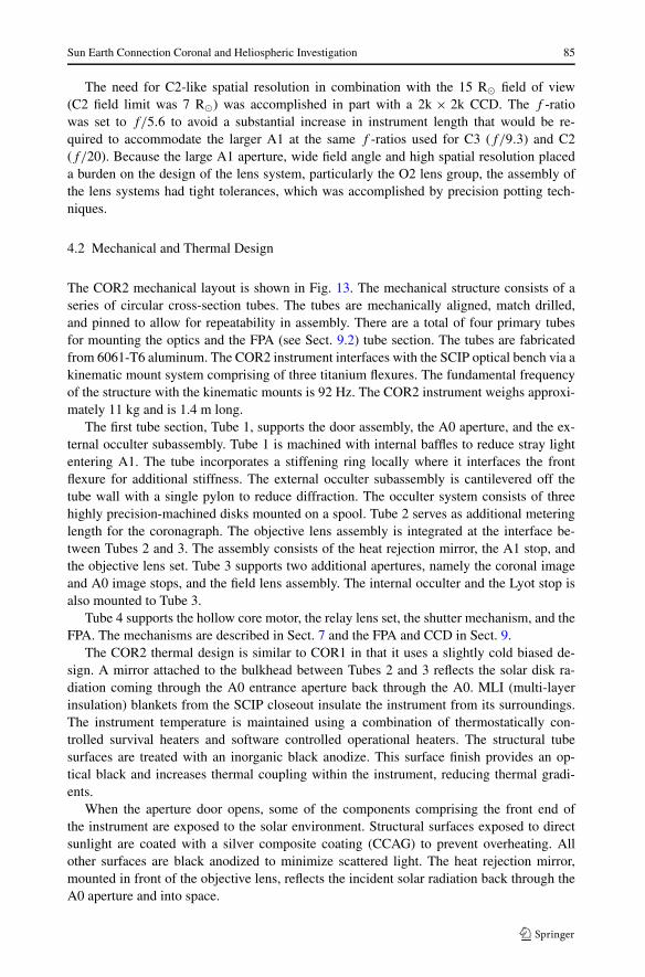
4.2 Mechanical and Thermal Design
The COR2 mechanical layout is shown in Fig. 13. The mechanical structure consists of aseries of circular cross-section tubes. The tubes are mechanically aligned, match drilled,and pinned to allow for repeatability in assembly. There are a total of four primary tubesfor mounting the optics and the FPA (see Sect. 9.2) tube section. The tubes are fabricatedfrom 6061-T6 aluminum. The COR2 instrument interfaces with the SCIP optical bench via akinematic mount system comprising of three titanium flexures. The fundamental frequencyof the structure with the kinematic mounts is 92 Hz. The COR2 instrument weighs approxi-mately 11 kg and is 1.4 m long.
The first tube section, Tube 1, supports the door assembly, the A0 aperture, and the ex-ternal occulter subassembly. Tube 1 is machined with internal baffles to reduce stray lightentering A1. The tube incorporates a stiffening ring locally where it interfaces the frontflexure for additional stiffness. The external occulter subassembly is cantilevered off thetube wall with a single pylon to reduce diffraction. The occulter system consists of threehighly precision-machined disks mounted on a spool. Tube 2 serves as additional meteringlength for the coronagraph. The objective lens assembly is integrated at the interface be-tween Tubes 2 and 3. The assembly consists of the heat rejection mirror, the A1 stop, andthe objective lens set. Tube 3 supports two additional apertures, namely the coronal imageand A0 image stops, and the field lens assembly. The internal occulter and the Lyot stop isalso mounted to Tube 3.
Tube 4 supports the hollow core motor, the relay lens set, the shutter mechanism, and theFPA. The mechanisms are described in Sect. 7 and the FPA and CCD in Sect. 9.
The COR2 thermal design is similar to COR1 in that it uses a slightly cold biased de-sign. A mirror attached to the bulkhead between Tubes 2 and 3 reflects the solar disk ra-diation coming through the A0 entrance aperture back through the A0. MLI (multi-layerinsulation) blankets from the SCIP closeout insulate the instrument from its surroundings.The instrument temperature is maintained using a combination of thermostatically con-trolled survival heaters and software controlled operational heaters. The structural tubesurfaces are treated with an inorganic black anodize. This surface finish provides an op-tical black and increases thermal coupling within the instrument, reducing thermal gradi-ents.
When the aperture door opens, some of the components comprising the front end ofthe instrument are exposed to the solar environment. Structural surfaces exposed to directsunlight are coated with a silver composite coating (CCAG) to prevent overheating. Allother surfaces are black anodized to minimize scattered light. The heat rejection mirror,mounted in front of the objective lens, reflects the incident solar radiation back through theA0 aperture and into space.

86 R.A. Howard et al.
4.3 Calibration and Performance Results
The COR2 calibration plan involved testing at both the component and telescope levels.The properties of the linear polarizers were measured in the lab and the two best polar-izers were chosen for the flight instruments. The bandpass filters were manufactured andmeasured by Andover. The bandpass response was verified at NRL and again the best fil-ters were used in the flight instruments. The most extensive component-level testing wasperformed on the various lens sets of the COR2 optical train. A breadboard version of theinstrument was constructed to mount the 3 lens groups and to allow us to verify the opticalprescription. With the aid of an Air Force resolution target, we were able to measure theMTF at various field angles and choose the lens group combinations with the best imagingperformance.
The flight unit performance was measured at NRL’s Solar Coronagraph Optical TestChamber (SCOTCH) facility (Morrill et al. 2006). The same facility was used in a similarconfiguration for the COR1 calibration (Sect. 3.4.1). The instrument vignetting function andspectral response were measured in air. The stray light levels, image quality and absolutephotometric calibration were measured under vacuum. The tests were based on similar testsfor the SOHO/LASCO coronagraphs.
The COR2 vignetting pattern for the Ahead telescope is shown in Fig. 14. The image isvignetted throughout the field of view reaching a minimum of 20% at about 10 R� beforeincreasing again towards the edge. The vignetting around the occulter pylon is only about40–50%, which does not impede imaging and therefore the pylon will be invisible in theimages similarly to LASCO/C2.
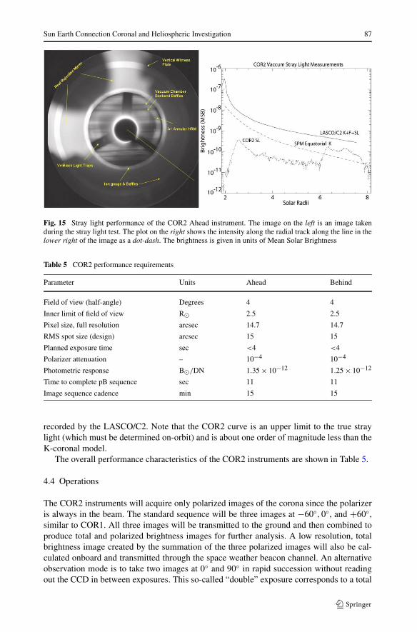
The stray light tests (Fig. 15) showed that the instrument performance exceeds the designrequirements and will allow us very detailed imaging of the extended corona. The image onthe left of Fig. 15 was taken during the stray light test and shows back-reflections onto bafflesin the chamber. The plot on the right is the intensity from the center outward to the lowerright corner of the image. It passes through one of the low-scatter surfaces (vel-black). Theeffectiveness of the vel-black is seen immediately in the contrast to the neighboring regionwhich is light being reflected onto the end of the chamber. On the plot is shown the intensityscan of the COR2 as the dot-dash curve, which is below the Saito et al. (1977) (SPM) modelof the K-corona as a dotted curve and the curve of the K- and F-coronae and stray light as
Fig. 14 Flat field response of the COR2 Ahead instrument. The plot on the right is an intensity cut diagonallyfrom the lower left to the upper right, through the pylon
Sun Earth Connection Coronal and Heliospheric Investigation 87
Fig. 15 Stray light performance of the COR2 Ahead instrument. The image on the left is an image takenduring the stray light test. The plot on the right shows the intensity along the radial track along the line in thelower right of the image as a dot-dash. The brightness is given in units of Mean Solar Brightness
Table 5 COR2 performance requirements
Parameter Units Ahead Behind
Field of view (half-angle) Degrees 4 4
Inner limit of field of view R� 2.5 2.5
Pixel size, full resolution arcsec 14.7 14.7
RMS spot size (design) arcsec 15 15
Planned exposure time sec <4 <4
Polarizer attenuation – 10−4 10−4
Photometric response B�/DN 1.35 × 10⁻¹² 1.25 × 10⁻¹²
Time to complete pB sequence sec 11 11
Image sequence cadence min 15 15
recorded by the LASCO/C2. Note that the COR2 curve is an upper limit to the true straylight (which must be determined on-orbit) and is about one order of magnitude less than theK-coronal model.
The overall performance characteristics of the COR2 instruments are shown in Table 5.
4.4 Operations
The COR2 instruments will acquire only polarized images of the corona since the polarizeris always in the beam. The standard sequence will be three images at −60◦,0◦, and +60◦,similar to COR1. All three images will be transmitted to the ground and then combined toproduce total and polarized brightness images for further analysis. A low resolution, totalbrightness image created by the summation of the three polarized images will also be cal-culated onboard and transmitted through the space weather beacon channel. An alternativeobservation mode is to take two images at 0◦ and 90◦ in rapid succession without readingout the CCD in between exposures. This so-called “double” exposure corresponds to a total

88 R.A. Howard et al.
brightness image and is transmitted to the ground as a single image. This is useful way tosave telemetry and increase image cadence for special observations. More details about theinstrument operations are given in Sect. 11.
5 The Heliospheric Imagers (HI)
5.1 Instrument Concept
The HI objectives, like the rest of the SECCHI suite, are to make visible light observationsof CMEs and other structures as they transit from the corona and into the heliosphere. TheHI package consists of two small, wide-angle telescope systems (HI-1 and HI-2) mountedon the side of each STEREO spacecraft, which together view the region between the Sunand Earth. HI has no mechanisms, other than a one-shot door that protects the instrumentfrom contamination during ground operations and launch. Thus, an image is collected in theshutterless mode, in which the intensity at each pixel is an accumulation of the static sceneand a smearing of the image during readout. This smearing can be removed on the ground.
The HI instrument concept was derived from the laboratory measurements of Buffingtonet al. (1996) who determined the scattering rejection as functions of the number of occultersand the angle below the occulting edge. The concept is not unlike observing the night skyafter the Sun has gone below the horizon.
While the specific concept used here has not been flown before, two other instrumentshave flown which have validated the ability to measure the electron scattered componentagainst the strong zodiacal light and stellar background. The Zodiacal Light Photometer(Pitz et al. 1976) on the Helios spacecraft, launched in 1974, and from the Solar MassEjection Imager (SMEI) instrument (Eyles et al. 2003), on the Coriolis spacecraft, launchedin 2003 have demonstrated that a properly baffled instrument can detect CMEs (Tappin et al.2003).
The performance specifications for HI are listed in Table 6. The HI-1 and HI-2 tele-scopes are directed to angles of about 13 degrees and 53 degrees from the principal axisof the instrument, which in turn is tilted upwards by 0.33 degrees to ensure that the Sun issufficiently below the baffle horizon. Thus, the two fields of view are nominally set to about
Table 6 Performance specifications of the HI telescopes
HI-1 HI-2 Units
Direction of centre of FOV 13.98 53.68 Degrees
Angular field of view 20 70 Degrees
Angular range 3.98–23.98 18.68–88.68 Degrees
Image array (2 × 2 binning) 1024 × 1024 1024 × 1024 Pixels
Image pixel size 70 arcsec 4 arcmin arcsec
Spectral bandpass 630–730 nm 400–1000 nm nm
Nominal exposure time 12–20 s 60–90 s sec
Typical exposures per image 150 100
Nominal image cadence 60 min 120 min min
Brightness sensitivity 3 × 10⁻¹⁵ 3 × 10⁻¹⁶ B�Straylight rejection (outer edge) 3 × 10⁻¹³ 10−14 B�

Sun Earth Connection Coronal and Heliospheric Investigation 89
Fig. 16 The geometrical layoutof the HI fields of view and themajor intensity contributions(based on a figure from Socker etal. 2000)
14 and 54 degrees from the Sun, along the ecliptic line, with fields of view of 20 and 70degrees, respectively. This provides on overlap of about 5 degrees.
The geometrical layout of the fields of view of the SECCHI instruments is shown in thetop half of Fig. 16. The HI-1 and HI-2 fields provide an opening angle from the solar equatorat 45◦, chosen to match the average size of a CME. This configuration provides a view ofthe Sun-Earth line extending from the COR2 outer limit to Earth. Since these observationsare done from both spacecraft a stereographic view of an Earth-directed CME is obtainedas it propagates through the inner heliosphere. In the bottom half of Fig. 16 are shown themajor contributions to the observed intensities: the sum of the F-corona (zodiacal light) andK-corona (electron scattering), and the anticipated CME intensities. Note that the F + K-coronal intensity is about two orders of magnitude brighter than the CME signal.
The anticipated instrument stray light level must be at least an order of magnitude lessthan the F-coronal signal which can be seen, from Fig. 16, to require levels of better than∼3×10⁻¹³ B� for HI-1 and ∼10−14 B� for HI-2, where B� is the mean intensity of the solardisk. In contrast, the brightness sensitivity requirement is based on the need to extract theCME signal from the other signal sources, which demands the detection of CME intensitiesdown to 3 × 10⁻¹⁵ B� and 3 × 10⁻¹⁶ B�.
5.2 Baffle Design
The baffle design is the key to the HI concept. As shown in Fig. 17, the baffle sub-systemsconsist of a forward baffle, a perimeter baffle along the sides and rear and the internal bafflesystem. The forward baffle is designed to reject the solar disk intensity, reducing straylightto the required levels. The perimeter baffle is principally aimed at rejecting straylight fromthe spacecraft, and the internal baffle system is aimed at rejecting light from the Earth andstars.
The forward baffle protects the HI-1 and HI-2 optical systems from solar light using aknife-edge cascade system, as demonstrated in Fig. 18. The five-vane system allows the re-

90 R.A. Howard et al.
Fig. 17 Left: The Heliospheric Imager structural concept. Right: A schematic side view of the optical config-uration, demonstrating the two fields of view of the two telescopes and the orientation of the interior baffles
Fig. 18 Comparison of observations of the diffraction from the cascade knife-edge system of the forwardbaffle system with the theoretical prediction
quired rejection to be achieved, as computed using Fresnel’s second order approximationof the Fresnel-Kirchhoff diffraction integral for a semi-infinite half-screen. The schematicplot in the top panel of Fig. 18 shows the nature of the function log (B/B�), where B� isthe solar brightness, plotted with distance below the horizon. The heights and separations of

Sun Earth Connection Coronal and Heliospheric Investigation 91
the five vanes have been optimized to form an arc ensuring that the (n + 1)th vane is in theshadow of the (n − 1)th vane. The computed global rejection curve for this system is plot-ted in Fig. 18 (bottom panel), together with measurements made using a full 5-vane mockup baffle in ambient and vacuum conditions which show good adherence to the predictedrejection levels (Defise et al. 2003).
The perimeter baffle (sides and rear vane systems) protects the HI optical systems fromreflection of sunlight off spacecraft elements lying below the horizon defined by the baf-fles, including the High Gain Antenna, door mechanisms etc. However, one spacecraft ele-ment does rise above the baffles, namely the 6 m long monopole antenna of the SWAVESinstrument, although it is not in the field of view of the telescopes. However, from themeasured reflection measurements provided by the SWAVES team and calculations, thelevel of reflected light from the monopole entering the entrance aperture will be insignifi-cant.
The internal baffle system consists of layers of vanes which attenuate unwanted lightfrom multiple reflections into the HI-1 and HI-2 optical systems, mainly from stars, planetsthe Earth, zodiacal light and the SWAVES monopole. Although the Earth, stars and plan-ets may be within the HI fields, the internal baffle system limits the uniform backgroundscattered into the optical systems.
5.3 Optical Systems
Figure 17 shows the locations of the HI-1 and HI-2 optical units. The optical configurationsfor these are shown in Fig. 19. These systems have been designed to cater for wide-angleoptics, with 20◦ and 70◦ diameter fields of view, respectively, with good ghost rejection,using radiation tolerant glasses (as indicated by the notation for each lens). The HI-1 lenssystem has a focal length of 78 mm and aperture of 16 mm and the HI-2 system has a20 mm focal length and a 7 mm aperture. The design is optimized to minimize the RMS spotdiameter and anticipates an extended thermal range from −20◦C to +30◦C. The detectorsystem at the focus in each case is a 2048 × 2048 pixel 13.5 micron CCD.
The lens assemblies have undergone detailed design and test procedures and one of thekey requirements is on the stray light rejection; the lens systems are mounted in blackenedbarrels. For HI-1 and HI-2 stray light rejection is measured to be at 10−3 or lower. Thiscombined with the stray light measurement of the front baffle, shown in Fig. 18, provides anoverall light rejection level of 10−11–10−14 for HI-1 and 3 × 10⁻¹⁵ for HI-2. These valuesare better than the straylight requirements (Table 6).
5.4 Mechanical Structure
The basic design concept for HI can be seen in Fig. 17. The instrument is a 720 (L) ×420 (W) × 240 (H) mm box. A door covers the optical and baffle systems during launchand the initial cruise phase activities. The door is designed for single-use operation and willbe opened after all contamination generating spacecraft propulsion events have occurredprior to insertion into heliocentric orbit.
The HI structure has 6 components: (1) a five-sided box with stiffening braces, (2) thelinear baffle assembly, (3) the perimeter baffle assembly, (4) an interior baffle assembly,(5) telescope trunion mounts and (6) the FPAs. The box is an aluminum honeycomb struc-ture with carbon-fiber (CFRP) face sheets. The face sheets were either 3 or 6 layers inwhich the layers were oriented at 60 degrees to each other to create pseudo-isotropic ther-mal characteristics. The 3 layer layups were used in non-load bearing areas. The temperature

92 R.A. Howard et al.
Fig. 19 The optical configurations of the HI-1 (upper) and HI-2 (lower) lens assemblies
extremes in the instrument are expected to be on the order of 100◦C and the relationship be-tween the front baffle assembly to the HI-1 and HI-2 optical axes must be held to within 125and 240 arcsec (respectively). The baffles are made with 6–8 layers of face sheet layups.The exposed CFRP surfaces were painted with Chemglaze Z307 black paint. The structuremet the requirement to have the first natural frequency resonance at or above 50 Hz. Thespacecraft mounts were similar to those described in Sect. 7.1.
5.5 Operations
In order to extract the CME signal from the much more intense background of Zodiacallight and stellar background, the SNR must be increased over a single exposure. This isaccomplished by summing individual exposures on-board. This requires that the individualimages be scrubbed for cosmic rays, prior to summing and also prior to being 2 × 2 pixelbinned. This 2 × 2 binning results in angular sizes of 70 arcsec (HI-1) and 4 arcmin (HI-2)per pixel. The combination of summing 50 images and 2 × 2 binning results in an increasein the SNR of about 14×. For each telescope, Table 6 lists a nominal exposure time rangeand typical number of exposures per summed image. Since there is no shutter, a smearingwill occur during the readout. Software to remove this effect was applied to images takenduring thermal-vacuum testing with excellent results.
A simulation of the instrument performance has been reported in Harrison et al. (2005).In that study the scene was simulated by adding the contributions from the F-corona,

Sun Earth Connection Coronal and Heliospheric Investigation 93
K-corona, stars, planets, and the instrumental characteristics such as point spread function,stray light, photon noise and the shutterless operation. In this background a simulated CMEwas launched and shown to be detectable.
6 Guide Telescope
The SECCHI Guide Telescope (GT) is mounted on the SCIP and serves two main purposes:
1. The GT acts as the spacecraft fine sun sensor.2. The GT provides the error signal for the EUVI fine pointing system (FPS).
The GT images the Sun onto an occulter, which is sized to block most of the solar disk and topass only the solar limb. The intensity of the limb is measured in 4 sections by photodiodes,placed 90° apart. The concept is based on the guide telescope for the TRACE Small Explorermission.
The optical system consists of an achromatic refractor with bandpass entrance filter anda Barlow lens (Fig. 20). A set of 4 redundant photodiodes behind an occulter measure thelocation of the solar limb (Fig. 21). The signals from the photodiodes are amplified andpassed to the SECCHI Electronics Box. Table 7 lists key parameters of the GT. In contrastto the TRACE GT, the SECCHI GT has no provisions for off-pointing the GT relative to thescience telescopes. The focal length of the GT for SECCHI is shorter than for TRACE, andis different for the Ahead and the Behind observatories. This extends the range of apparentsolar diameters that the GT can accommodate, and allows the GT to operate throughout theelliptical orbit of each STEREO observatory.
The analog photodiode signals from the GT pre-amplifier are sampled every 4 ms bya 12-bit analog-to-digital converter in the SECCHI Electronics Box. The SECCHI flightsoftware converts the four diode voltages into pitch and yaw pointing error signals, and aset of four sun presence flags (one flag for each photodiode). Those signals are sent to thespacecraft. If all four photodiodes are illuminated, then the sun is within the linear range ofthe GT, all four sun presence flags are set, and the error signals are valid. If only one, two,or three photodiodes are illuminated, then the sun is within the acquisition range of the GT,and the STEREO spacecraft uses the sun presence flags to acquire the sun. The SECCHIflight software further processes the GT error signals to generate the drive voltages for theactive secondary mirror of the EUVI Fine Pointing System.
Fig. 20 Schematic cross section of the SECCHI Guide Telescope

94 R.A. Howard et al.
Fig. 21 Guide Telescope sensor head with occulter and photodiodes
Table 7 Key Guide Telescope parameters
Optics Achromatic refractor with Barlow lens
Lens materials Radiation hardened glass
Aperture 27 mm (aperture stop at objective lens)
Focal length Ahead: 1454 mm, Behind: 1562 mm
Bandpass filter Center wavelength: 570 nm, bandwidth: 50 nm (FWHM)
Limb sensor 4 (+4 redundant) photodiodes
Telescope structure Aluminum
Acquisition range >±20 arcmin (worst case)
Linear range >±70 arcsec (worst case Aphelion)
Pre-amplifier Two selectable gains: sun/stimulus telescope (artificial sun)
Noise <0.4 arcsec (3σ , single sample)
Sample frequency 250 Hz (digital sampling in SEB)
7 SCIP Bench
The SCIP (Sun Centered Instrument Package) structure supports the four SCIP telescopes(COR1, COR2, EUVI, and GT), the two SCIP electronics boxes (SCIP CEB and MEB), andthe associated harnesses and thermal blankets. The design of the SCIP structure is drivenby several requirements. The structure must (1) provide easy mounting and accessibility

Sun Earth Connection Coronal and Heliospheric Investigation 95
for component and spacecraft integration, (2) preserve the unobstructed field of view re-quirements of each telescope, (3) facilitate co-alignment activities and preserve telescopeco-alignment on-orbit, (4) be sufficiently stiff to avoid coupling with spacecraft and launchvehicle modes, and (5) meet a stringent mass budget while surviving test and launch loads.
The SCIP structure is a simple optical bench. The four telescopes are mounted on oneside of the bench while the electronics boxes are mounted on the opposite side. Several holesthrough the bench allow harnessing to pass between the telescopes and the electronics. TheSCIP bench is a 6.3 cm thick aluminum honeycomb panel (112 cm × 70 cm) with highmodulus graphite/cyanate ester face sheets. Face sheet layup is biased for high shear stiffnessand a resulting higher torsional stiffness of the optical bench. The design provides sufficientstiffness to meet the 50 Hz SCIP assembly first natural frequency requirement (measured a54 Hz first mode, bench torsion, during assembly vibration testing).
An additional thermal tent structure is attached to the bench to support an enclosure ofthermal blankets over the telescopes. The thermal tent structure is comprised of 0.5 cm hon-eycomb panels at the sun and anti-sun ends of the bench with tubular stringers connectingthe panels. Thermal blankets are draped over the structure to control the thermal and con-tamination environments inside the enclosure and provide insulation from the spacecraftcylinder. This generates a very uniform thermal environment for the SCIP telescopes.
7.1 SCIP Flexure Mounts
A key requirement of the SCIP structure is its ability to facilitate instrument co-alignmentand maintain it throughout the test program and instrument life on-orbit. The key to meetingthis challenging requirement is the development of a flexure-based near-kinematic mount-ing scheme. The scheme incorporates a set of three flexure mounts for each telescope. Eachmount is very stiff in the normal and lateral directions and much less stiff in the axial direc-tion and in the three directions of rotation. Acting as a set of three, the mounts provide a fullyconstrained, but not over-constrained, mounting scheme. The design of the flexure mountshas several distinct advantages: (1) The ratio of modulus in the “stiff” directions to themodulus in the “released” degrees of freedom provides an essentially kinematic mountingsystem. (2) The kinematic nature of the mounts minimizes thermal stress in the telescopes,preserves co-alignment on-orbit and allows shimming of the telescopes without inducingstress in the telescope tube structure. Shimming of the telescopes was performed with 5arcsec resolution. (3) The mounts utilize snug fitting pins at each interface to prevent shiftsafter integration and assure co-alignment repeatability when a telescope is removed and re-installed. (4) The titanium alloy provides high strength and stiffness with low mass, andlarge thermal isolation.
7.2 Analysis and Testing
The primary analysis tool for the SCIP structure was a MSC/NASTRAN finite elementmodel. The SCIP optical bench was modeled in detail, including models of each telescopeand of the electronics box, with a 189,000 degree-of-freedom model. Due to the develop-mental effort on the flexure mounts, a highly detailed (140,000 degree-of-freedom) modelwas constructed to analyze high stress areas and predict mount stiffness. Based on the de-tailed model, a simplified model of the mount was constructed for use in the assembly-levelmodel. The full assembly-level model was used to predict assembly first frequency, assessstress levels in the structure, derive component test spectrums and interface loads, and pre-dict on-orbit telescope alignment shifts due to thermal loads.

96 R.A. Howard et al.
Significant testing was performed to correlate the finite element results and load test theflight structures. The flexure mounts went through two rounds of prototype testing before theflight design was finalized. A monolithic telescope simulator facilitated testing of the mountsystem to determine its mounting stiffness. After the flight hardware was manufactured,other simulators were constructed to be used in static and dynamic load testing of the flightarticle. The test results were used to validate the component test spectra that were used toqualify the telescopes before they were integrated with the flight optical bench.
8 Mechanisms
The SECCHI SCIP telescope suite contains a total of 10 mechanisms of 6 distinct designs.EUVI has a focal plane shutter, filter wheel, and a quadrant selector. The COR1 and COR2telescopes each have a focal plane shutter and polarizer mechanism. All three of the SCIPtelescopes have a door mechanism. The HI telescopes have one mechanism, a door, whichwas discussed in Sect. 4.
All mechanisms have heritage from previous flight programs. The SCIP door mecha-nisms are based on a SOHO-LASCO design. The EUVI quadrant selector is an evolutionfrom the mechanism used in the TRACE quadrant selector, in that there are no restrictionsin the frequency of changes between telescope quadrants. The EUVI filter wheel, COR2and COR2 polarizer wheels and shutter mechanisms are nearly identical to the ones used onGOES SXI-N (Stern 2003).
8.1 SCIP Aperture Doors
The re-closable doors of the EUVI, COR1 and COR2 telescopes are referred to as theSESAMEs (SECCHI Experiment Sun Aperture Mechanisms). In total there are two sets ofSESAMEs, one for each SCIP assembly (Fig. 22). The prime objectives of the re-closabledoors are to protect the sensitive optics of the telescopes from damage due to contaminationduring ground operations, but also at critical times during flight operations. The launch of
Fig. 22 Top front view onto the SCIP-B assembly after integration into observatory B. From left to right:COR 1, EUVI and COR 2 doors. The SCIP-A doors are identical

Sun Earth Connection Coronal and Heliospheric Investigation 97
the Delta rocket generates large acoustic vibrations requiring the door lids to be pressedtightly against the telescope entrance apertures without generating particles. The EUVI isespecially sensitive because the lid has to protect the thin optical filters lying directly be-hind it. The doors also help to maintain the cleanliness of the optical systems from externalcontaminants that may be caused during thruster firings to control the orbit of the STEREOspacecraft. Because of momentum desaturation the thrusters will be fired about every 6 dayson average, implying that the COR doors will be cycled about 120 times during the two-yearnominal operations period. Re-closable doors are also required because the optical systemsmust open and close during ground testing and calibration of the optical systems.
All three doors have a similar baseline design. Each is operated by a stepper motor whichdrives a special screw-ball bearing mechanism to open and close the lids. In case of themalfunction of the motor a paraffin actuator acts as the failsafe device to open the doorpermanently. The command to “fire” the paraffin actuation is controlled by the spacecraft.The doors can be driven by the motors into different positions: superclosed, closed, crackedand open. The superclosed position presses the door lid against the aperture to withstand thelaunch environment, which could cause the lid to vibrate against the telescope tube. Thisvibration would create particles. The closed position is the normal closed position withoutthe launch pre-load. The cracked position is an intermediate position between closed andopen to permit outgassing to occur after launch. The open position is the normal positionfor science operations. The lid designs of EUVI, COR1 and COR2 have different sizes andstructures, with calibration windows being integrated into the COR lids. The opening angleof the EUVI door is 90 degrees, that of the COR doors is 270 degrees.
8.2 Shutters
The EUVI, COR1 and COR2 shutter designs are based on shutters that have successfullyflown on SOHO/MDI, TRACE (Akin et al. 1993), and Solar-B/FPP and will be flown onGOES-N/SXI. Both consist of a brushless DC motor with an optical encoder to which isattached a thin circular blade with a 120◦ opening that is positioned in front of the telescope’sfocal plane. The motor rotates the blade to open the shutter, exposing the CCD. The bladeis rotated in the same direction to close the shutter. The SECCHI shutters are capable ofexposures from 40 ms to 67 seconds in a programmable mode that are repeatable to betterthan 15 µs and uniform across the CCD to 50 µs. The exposure length can be indefinite whenopen and close motions are controlled directly by the SEB.
8.3 Quadrant Selector
The EUVI quadrant selector is nearly identical in design to the coronagraph shutters. Themotor rotates a blade with a 90◦ opening just behind the telescope’s thin-film entrance filters.The mechanism is commanded to rotate in 90◦ increments in approximately 45 ms to maskoff all but one of the telescope’s four EUV channels.
8.4 EUVI Filter Wheel
EUVI also incorporates a four position filter wheel just behind the telescope’s shutter. Thefilter wheel consists of a 101 mm diameter brushless DC motor surrounding a rotor with four32 mm diameter through holes. The mechanism will be launched with the filter wheel in theopen position, leaving the telescope beam-path open and protecting the three-filter positionwithin the mechanism housing. Operation time between two adjacent filter positions is ap-proximately 300 ms. Like the SECCHI shutters, the filter wheel has heritage from TRACE,MDI, SXI, and FPP.

98 R.A. Howard et al.
8.5 Polarizer Wheel
The coronagraph polarizer mechanism, also known as the hollow-core motor (HCM), is themost unique of the SECCHI mechanisms. Its design is derived from a similar mechanismused with success in MDI. It has a 144 step brushless DC motor similar to that used forthe EUVI filter wheel. A large-diameter, thin-section bearing supports a stainless steel rotorwith Teflon toroid separators. The space inside the bearing is left open, providing a 48 mmclear aperture for the coronagraph light bundle. With the 144 step motor design, the polar-izing optic that is mounted to the rotor can be positioned in 2.5◦ increments. During normalobserving operations, the polarizer mechanism will rotate 120◦ with an angular repeatabilityof better than 30 arcseconds. It makes this move in approximately 400 ms.
8.6 Lifetime Requirements
The lifetime requirements for each of the SECCHI mechanisms are 2.1 million operationsfor the EUVI quadrant selector, filter wheel, and shutter and 0.6 million operations for theCOR polarizer mechanisms and shutters. Comprehensive life testing was completed to provethe designs of the EUVI quadrant selector, coronagraph shutter, and HCM. These mecha-nisms underwent vibration to levels greater that for flight, thermal functional testing, andflight like operation in vacuum to three times their design lifetime. The quadrant selectorwas qualified to 8 million operations, the coronagraph shutter qualified to 2.8 million oper-ations, and the polarizer mechanism qualified to 3.5 million operations with no degradationin performance. The designs for the EUVI filter wheel and shutter were previously provento be capable of more than 32 million operations.
9 SECCHI Electronics
SECCHI contains three types of electronics arranged into 4 different boxes. The main elec-tronics is contained within the SECCHI electronics box (SEB) and is described in Sect. 9.1.The SCIP mechanisms are driven from a remote electronics box, described in Sect. 9.2. TheSCIP and HI cameras are driven from remote electronics boxes, called the Camera Electron-ics Box (CEB) and described in Sect. 10.3.
9.1 The SECCHI Electronics Box (SEB)
The SEB (SECCHI Electronics Box) is the payload controller for the SECCHI InstrumentPackage on the STEREO spacecraft, controlling and monitoring all SECCHI hardware.A block diagram of the SEB is shown in Fig. 23. The SEB provides the instrument’s inter-face to the spacecraft via the MIL-STD-1553 and power interfaces. It receives and distributescommands from the spacecraft and collects and converts state of health telemetry data be-fore providing it to the spacecraft. Image data from the telescopes (2 channels, 100 MB/s)is received over two SpaceWire ports and is then processed, compressed, and transmittedacross the 1553 interface to the spacecraft for downlink. The SEB had to be designed tomeet stringent program EMI requirements, as will be discussed briefly below. An Engi-neering Development Model (EDM) was designed and built before the flight hardware as apathfinder for the designs. This EDM is now part of the software testbed that will be main-tained during the life of the mission. The flight hardware underwent EMI/EMC, vibrationand thermal-vacuum testing before integration with the SECCHI instrument packages.

Sun Earth Connection Coronal and Heliospheric Investigation 99
Fig. 23 SECCHI Electronics Box (SEB) functional block diagram
9.1.1 Motherboard
The SEB Motherboard provides electrical connectivity between all cards housed within theSEB enclosure. It is a customized, cPCI compliant, five (5) slot, 6U back plane. The first four(4) cPCI slots which utilize the PCI signaling strictly adhere to the cPCI specification. Thefifth slot which does not use the PCI signaling has been customized for communications onthe user defined connectors, P3/P4/P5. Unused cPCI connectors were eliminated from thedesign.
9.1.2 Electrical Power
The SEB must interface to the spacecraft’s unregulated power bus. The electrical power sys-tem provides this interface as well as power conversion, control and distribution. Due to EMIrequirements, the electrical power system was divided into two (2) functional assemblies—the DC/DC converters and related circuitry (PSIB) and the power interface and distributionfunctions (PIB).
The PIB interfaces to the primary spacecraft power bus through a front panel connectorand routes this power off the motherboard and through the EMI cavity line filter panel, tothe DC/DC converters in the small EMI cavity. Regulated secondary power is then routedback from the DC/DC converters to be distributed throughout the SEB and SECCHI sys-tem by the PIB card. Internal secondary SEB power is distributed across the motherboardas required. External SECCHI power is routed through PIB I/O connectors and, in somecases, across the motherboard and out through the HKP I/O connectors due to front panellimitations. Power control signals are generated from gate arrays resident on the HKP card,

100 R.A. Howard et al.
as commanded by the RAD750 processor card. The HKP card determines the proper com-mands to send to the PIB and uses a serial interface across the motherboard to transfer theinformation. The PIB also provides motor drive power from control signals generated on theHKP. Voltage and current monitoring circuits on board provide state of health telemetry tothe HKP for conversion and, ultimately, downlinking. This card also houses the operationalheater drive circuits with appropriate switching for thermal control of the instrument pack-age. The heaters are again controlled via the HKP card since the PIB has no interfaces withthe processor for real estate and design simplification reasons. A second power bus from thespacecraft is distributed to SECCHI decontamination heaters through latching relays on thiscard.
The PSIB assembly resides in the small EMI cavity and includes three (3) DC/DC con-verters that provide all secondary power for the SEB and SECCHI system, as well as allnecessary filtering and protection. A single converter provides +3.3 Vdc power for internallogic. A triple output converter provides +5 VDC for internal and external legacy logic and+/−15 Vdc power for analog functions. The third converter provides +15 Vdc dedicatedfor “noisy” motors and mechanisms. Primary and secondary power interfaces, to the maincavity, are through an EMI filter panel.
9.1.3 RAD750 Processor
The SEB RAD750 processor, procured from BAE Systems, provides all processing requiredfor the SECCHI system and the control of all SEB circuitry via the cPCI backplane. Atthe core is a custom Power PCI Bridge chip providing the interface between the PowerPC750 and the cPCI bus. The primary computing resource is the radiation hardened PowerPC750. The RAD750 card provides for 256 kbytes of EEPROM StartUp ROM (SUROM) and128 Mbytes of SDRAM. SDRAM EDAC can correct nibble errors and detect double nibbleerrors. The card provides a self-refresh mode and scrubbing for the SDRAM. The RAD750is capable of 120MIPS and is being run at 116 MHz in the SECCHI application. This cardis the only 3U card in the SEB.
9.1.4 MIL-STD-1553 Interface Card (1553)
The 1553 card provides a fully compliant MIL-STD-1553 Remote Terminal (RT) bus inter-face to the spacecraft and 3 Mbytes of EEPROM storage for software application code. The1553 interface is the only communications interface with the host spacecraft. All commands,data uploads and telemetry are communicated across this bus. Full redundancy makes this avery robust interface. The EEPROM is arranged as two (2) banks of 1.5 Mbytes × 16 bitswide. This storage is fully accessible across the cPCI bus and provides for redundant flightsoftware storage.
9.1.5 SpaceWire Interface Card (SWIC)
The SWIC provides two (2) 100 Mb/s, simultaneous SpaceWire compatible links to theSCIP and HI instruments respectively. All image data and camera setup commands are trans-ferred using these interfaces. The TSS901E ASIC, from Atmel, provides these SpaceWirelinks. 256 Mbytes of SDRAM allows for temporary image storage while awaiting retrievaland processing by the RAD750, and can also be used by the processor for data storage orprogram execution. The SDRAM is complete with programmable refresh, scrubbing andEDAC. To efficiently move large amounts data, the PCI interface can be configured forDMA transfers, on to or off of the SWIC.

Sun Earth Connection Coronal and Heliospheric Investigation 101
9.1.6 Housekeeping Card (HKP)
The HKP is the bridge between the analog interfaces and the digital cPCI bus for the SEB.It controls serial data transfers with the SCIP mechanisms controller (Mechanisms Elec-tronics Box—MEB hardware) for shutter control and other commands. All SECCHI doorstatus is monitored and made available by the HKP. A regulated current source providesselectable drive for SECCHI calibration LED illumination. Analog Guide Telescope signalsare received and digitized by the HKP at a 250 Hz rate for delivery to the processor for trans-fer to the spacecraft’s Attitude Control System (ACS). Sixty three analog telemetry points,including voltage, current and temperature sensors, for both SEB internal and SECCHI ex-ternal, are digitized (0 to +10 V range, 12 bit conversions) and made available to the systemprocessor for use in fault detection and isolation and general state of health monitoring.
9.1.7 Enclosure
The enclosure was machined from a single block of aluminum. It includes 2 compartmentsallowing EMI isolation of the internal DC/DC converters. The bottom and one side haveremovable covers with labyrinth seals. Individual cards are installed from the top, with eachcard having a connector bracket that provides additional EMI protection and structural tiepoints. One final top cover, with clearance for each connector, completes the EMI seal. TheDC/DC converters reside in a separate “EMI cavity” isolated from the main cavity. Theinterface between the 2 cavities is achieved with an EMI-tight, filter capacitor panel.The overall dimensions are 198 × 292 × 267 mm (H × W × L), weighing 9.4 kg.
9.2 Mechanism Electronics Box (MEB)
All of the SECCHI SCIP mechanisms, with the exception of the telescope doors, are con-trolled by the SECCHI Mechanisms Electronics Box (MEB), which is mounted on the un-derside of the SCIP optical bench. Physically, the MEB is a 210 × 56 × 171 mm box witha mass of approximately 1.4 kg with connectors dedicated to power and commands fromthe SEB and each of the telescopes. The MEB inputs are a Low-Voltage Differential Signal(LVDS) from the SECCHI SEB, 5 V power for the MEB and mechanism encoders, ±15 Vpower to drive mechanism motors. The three LVDS inputs to the MEB from the SEB includea strobe, clock signal, and a serial command signal. A single return LVDS signal is sent backto the SEB. The MEB contains two boards and each has two Field Programmable Gate Ar-rays (FPGAs). The FPGAs on the first board control the EUVI shutter, quadrant selector,and filterwheel, and drive the EUVI Fine Pointing System (FPS). The two FPGAs on thesecond board each control a shutter and polarizer mechanism on each of the coronagraphs.
The MEB accepts low level commands such as “load target position,” “move clockwise”to that position, and “read current encoder position.” These commands are sequenced bythe SEB and there is no command buffer in the MEB. Table 8 provides a partial listing ofcommands accepted by the MEB in the order in which they are typically employed. MEBcommands are 16-bit and consist of an 8-bit command word and an 8-bit variable word suchas exposure time for a shutter or target position for the HCM.
The mechanism motors are driven by a 15 V, three-phase signal generated by the MEB inresponse to the signal provided by the optical encoders in each of the SECCHI mechanisms.The SECCHI MEB also drives the EUVI FPS, the design of which is discussed in a separatesection. The MEB accepts commands from the SECCHI SEB to derive three analog voltagesfrom 0–10 V to drive the ISS PZTs. There is no PZT or mirror position feedback to the MEB.

102 R.A. Howard et al.
Table 8 MEB commands
Command Action
RESET – HCM and filter wheel target and encoder reading cleared
– Shutters rotate to “ready for exposure” position, exposure time cleared
– Quadrant selector rotates to 284 Å quadrant, target cleared
LOAD TARGET HCM, filter wheel, and quadrant selector desired position saved
MOVE CW Mechanism moves to saved target
LOAD Shutter desired exposure time saved
EXPOSURE
CW EXPOSURE Shutter makes a 120◦ clockwise move to open position, waits for desired saved expo-sure time, and makes a 240◦ clockwise move to closed/ready position
READ ENCODER MEB returns to the SEB the current position of the mechanism
READ STATUS MEB returns to the SEB the current status of the mechanism
10 Charge Couple Device (CCD) Cameras
10.1 CCD Detectors
Each of the scientific instruments on SECCHI uses a three-phase, back-illuminated, non-non-inverted mode (to ensure good full well capacity, 150k to 200k electrons), CCD modelCCD42-40 manufactured by E2V in the United Kingdom. There are 2048 (H) × 2052 (V )
image pixels, each measuring 13.5 micron on a side and providing a total imaging area of27.6 mm square. The total readout is 2148 × 2052 pixels, providing 100 columns of non-imaging over and under-scan region for camera calibration and engineering purposes. Tworeadout ports on the left and right side of the imaging area are available. In principle the de-vice may be fully read through either port, or through both ports to double the readout speed.To save mass the SECCHI instruments use only one port, which is hard wired through theharness in our flight configuration, although non-flight harnesses were developed to testfrom either port. The CCDs used for visible light detection (COR-1, COR-2, HI-1 andHI-2) have an anti-reflective coating on their backside (illuminated side). Quantum effi-ciency (QE) of these devices is roughly 80% at 500 nm, 88% at 650 nm, 64% at 800 nm,and 34% at 900 nm. The backside of the EUVI CCD has no coating in order to providesensitivity at shorter wavelengths, with a quantum efficiency of 74% at 17.1 nm, 70% at30.3 nm, and 46% at 58.4 nm. CCDs are operated at a temperature design point of <−65°C.
The CCD is mounted on a custom ceramic carrier, which is precision mounted on aninvar chip carrier. Electrical connections are made through a flex-print cable secured to thecarrier, and a 25-pin micro-D connector. Figure 24 shows the SECCHI CCD in its flightpackage. The CCDs have excellent vertical and horizontal charge transfer efficiencies—better than 99.999%. The dark current generation rate is better than 2 nA/cm2/s at 20°C,which is equivalent to 24,000 electrons per pixel/s.
10.2 Focal Plane Assembly (FPA)
The SECCHI Focal Plane Assembly (FPA) provides the SECCHI CCDs with physicalmounting, optical positioning, electrical connection, and thermal cooling. The basic FPA

Sun Earth Connection Coronal and Heliospheric Investigation 103
Fig. 24 SECCHI CCD in its package with flexprint harness attached. The CCD size is 28.1 mm × 30.3 mm
design for SECCHI was used on all five telescopes. All five assemblies are nearly identicalexcept for differences in the length and shape of the cold finger, radiator size and shape andfocal plane masks.
The requirements for the design of the FPA were: (1) Cool the CCD using passive radi-ation techniques to <−65°C using an aluminum cold finger coupled to a surface radiatingto deep space; (2) Position the CCD at the focal plane of the telescope, perpendicular to theoptical axis and aligned to the optical axis; (3) Keep the CCD positioned at room and operat-ing temperatures; (4) Provide a capability to add a spacer in between the FPA and telescopemounting flange to account for different focal plane positions of the various telescopes andto account for any focal plane shift between room and operating temperatures; (5) Providea capability to heat the CCD to at least 30°C to drive off contaminants and to “anneal” theCCD after radiation damage; (6) Provide a cold cup at a temperature slightly colder than theCCD to act as a contamination shield for the CCD.
Figure 25 shows a cutaway of an FPA assembly as viewed from the front/side and alsoin the lower right as viewed from the rear/side. At operating temperatures, the CCD will bebelow −60°C and the mounting flange will be about 20°C. The CCD is cooled to this lowtemperature by conducting away the heat from the CCD through an aluminum “cold finger”which then is attached at the back end to an aluminum thermal radiator plate that has a clearview to deep space. The CCD chip carrier is first bolted onto an invar block which has aheater coil in between the carrier and the block. The heater coil can heat the CCDs to above50°C. The invar block is attached to the cold finger, which runs inside an outer support tubeand attaches to the thermal radiator. The interior of the outer support tube and the cold fingerare gold plated to reduce the heat transmission between the two. At the mechanical interfaces
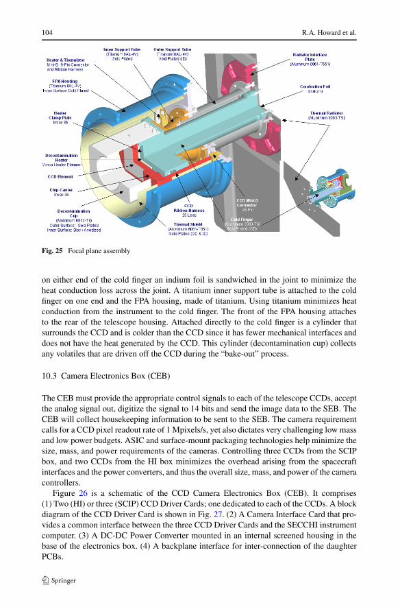
104 R.A. Howard et al.
Fig. 25 Focal plane assembly
on either end of the cold finger an indium foil is sandwiched in the joint to minimize theheat conduction loss across the joint. A titanium inner support tube is attached to the coldfinger on one end and the FPA housing, made of titanium. Using titanium minimizes heatconduction from the instrument to the cold finger. The front of the FPA housing attachesto the rear of the telescope housing. Attached directly to the cold finger is a cylinder thatsurrounds the CCD and is colder than the CCD since it has fewer mechanical interfaces anddoes not have the heat generated by the CCD. This cylinder (decontamination cup) collectsany volatiles that are driven off the CCD during the “bake-out” process.
10.3 Camera Electronics Box (CEB)
The CEB must provide the appropriate control signals to each of the telescope CCDs, acceptthe analog signal out, digitize the signal to 14 bits and send the image data to the SEB. TheCEB will collect housekeeping information to be sent to the SEB. The camera requirementcalls for a CCD pixel readout rate of 1 Mpixels/s, yet also dictates very challenging low massand low power budgets. ASIC and surface-mount packaging technologies help minimize thesize, mass, and power requirements of the cameras. Controlling three CCDs from the SCIPbox, and two CCDs from the HI box minimizes the overhead arising from the spacecraftinterfaces and the power converters, and thus the overall size, mass, and power of the cameracontrollers.
Figure 26 is a schematic of the CCD Camera Electronics Box (CEB). It comprises(1) Two (HI) or three (SCIP) CCD Driver Cards; one dedicated to each of the CCDs. A blockdiagram of the CCD Driver Card is shown in Fig. 27. (2) A Camera Interface Card that pro-vides a common interface between the three CCD Driver Cards and the SECCHI instrumentcomputer. (3) A DC-DC Power Converter mounted in an internal screened housing in thebase of the electronics box. (4) A backplane interface for inter-connection of the daughterPCBs.
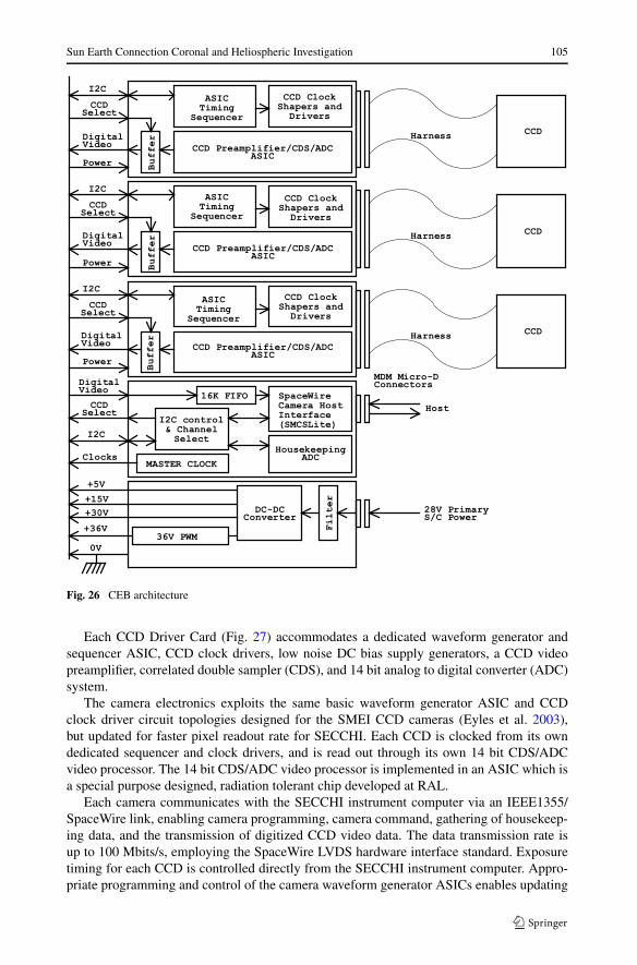
Sun Earth Connection Coronal and Heliospheric Investigation 105
Fig. 26 CEB architecture
Each CCD Driver Card (Fig. 27) accommodates a dedicated waveform generator andsequencer ASIC, CCD clock drivers, low noise DC bias supply generators, a CCD videopreamplifier, correlated double sampler (CDS), and 14 bit analog to digital converter (ADC)system.
The camera electronics exploits the same basic waveform generator ASIC and CCDclock driver circuit topologies designed for the SMEI CCD cameras (Eyles et al. 2003),but updated for faster pixel readout rate for SECCHI. Each CCD is clocked from its owndedicated sequencer and clock drivers, and is read out through its own 14 bit CDS/ADCvideo processor. The 14 bit CDS/ADC video processor is implemented in an ASIC which isa special purpose designed, radiation tolerant chip developed at RAL.
Each camera communicates with the SECCHI instrument computer via an IEEE1355/SpaceWire link, enabling camera programming, camera command, gathering of housekeep-ing data, and the transmission of digitized CCD video data. The data transmission rate isup to 100 Mbits/s, employing the SpaceWire LVDS hardware interface standard. Exposuretiming for each CCD is controlled directly from the SECCHI instrument computer. Appro-priate programming and control of the camera waveform generator ASICs enables updating

106 R.A. Howard et al.
Fig. 27 CCD driver card
of CCD readout waveform patterns and readout tables, and the initiation of various readoutmodes e.g. clearing, exposure, full-frame, windowed, or continuous readout. Pixel binning,programmable video gain, and programmable video DC offset level are also supported.
Each camera contains a DC-DC power converter that converts the incoming 28 V space-craft primary power to the required +5 V, +15 V, +30 V, and +36 V secondary supplies.The camera’s 28 V power supply input is in-rush current limited, and current-trip protected.The converter’s output supply rails are also filtered to minimize any noise and/or current-switching transitions on the supply rails to the CCD drive circuitry. The complete powerconverter system is screened from the CCD drive electronics within its own, shielded sub-housing within the CEB.
The survival power and decontamination heater power supplies for the CCDs are notrouted through the camera boxes, but go directly from the SECCHI instrument computer tothe CCD heads. Similarly, the temperatures of the CCDs are monitored directly from theSECCHI instrument computer and not through the camera electronics units. Housekeep-ing telemetry from the camera electronics enables the controller’s secondary power supplyvoltage rails and internal temperature to be monitored.
The SCIP camera electronics enclosure is 195 mm × 126 mm × 85 mm, including allmounting feet, connector, and fixing screw protrusions. The HI camera electronics enclosureis slightly smaller (195 mm × 126 mm × 70 mm) to conserve volume and mass.
Operationally, the camera will respond to the following modes:
Clear Clearing of the CCD will take advantage of the CCD’s ‘dump-drain’ running adja-cent to the serial output register. Appropriate programming of the ASIC waveform generatorwill allow the entire array to be cleared any number of times prior to integration.
Integration During integration, the CCD’s parallel register clocks will be held at appropri-ate voltage levels. The serial register clocks can be individually programmed to be high, low,or clocking. Dither clocking of the parallel register clocks will be possible to help minimizedark current generation, and to allow some degree of testing at room temperature.

Sun Earth Connection Coronal and Heliospheric Investigation 107
Readout Appropriate programming of the ASIC waveform generator will allow any num-ber of readout modes including:
(1) full-frame readout of n lines,(2) windowed readout of at least two windows (dump n lines, read x lines, dump m lines,
read y lines, etc.),(3) full-frame, or windowed readout with n × m pixel binning (pixel binning parameters
can be different between windows provided that the windows are not overlapping),(4) continuous clocking.
The size of the readout area (or image format) is programmable without restrictions. Mul-tiple windowed readout is possible up to the memory limits of the ASIC’s internal ‘readouttable’ memory. Window co-ordinates are programmable within CCD ‘readout tables’, butmust be specified from the control computer. Any variety of camera operating cycles willbe possible by appropriate programming of the waveform generator ASIC. Cycles may beimplemented as a series of short ‘readout tables’, individually initiated from the controlcomputer; or alternatively as one long ‘readout table’ initiated only at the beginning.
11 Flight Software
11.1 Flight Software Overview
The SECCHI flight software runs within a real-time, multi-tasking operating system, Vx-Works, that provides all of the software services needed by the instruments. This includeshandling commands from the spacecraft, housekeeping and science telemetry to the space-craft, heater control, guide telescope control, instrument control, image scheduling and im-age processing. The code is derived from code used in NASA’s Small Explorer (SMEX)series of satellites and from the SOHO/LASCO experiment which was then modified for theSECCHI instrument.
The VxWorks operating system provides the infrastructure for running multiple tasksand each of the major functions listed above are run as separate tasks that can be started,stopped or reloaded independently. This made modifying the heritage code easy since thecode is naturally modular. VxWorks also provides inter-task communications, which havebeen developed into a software bus library, shared by all tasks. The heritage software pro-vided a large amount of useful code which reduced our task to modifying the telemetry andcommand tasks for SECCHI hardware and STEREO spacecraft protocols, developing newtables, telemetry and commands within the SMEX framework and developing new SEC-CHI code for image scheduling, image processing and control of the SECCHI hardware,specifically cameras, mechanisms, heaters, power, housekeeping board. The SECCHI flightsoftware contains about 250,000 lines of code.
11.2 Instrument Scheduling
The STEREO spacecraft will use the NASA Deep Space Missions System for commandingand telemetry downlink. Only one or two 4-hour contacts per day per spacecraft are planned.During the contact time the uplink rate is 2 kbits/s shared between all instruments and thespacecraft, which means limited daily commanding and a need for handling large blocks ofschedule. The distance of the spacecraft from Earth and the resulting light travel time curtailsinteractive operations so that the instrument must perform most operations by programmedsequences on-board the instrument.

108 R.A. Howard et al.
The SECCHI concept of operations leads to the following characteristics for imagescheduling:
(1) Provide for an autonomous operation for long periods of time (1 week or more)(2) Synchronize image taking between spacecraft in which every image is scheduled(3) Handle some non-image taking operations in timeline (doors and script tasks)(4) Manage timeline of image taking and events to 1 second resolution(5) Accept relative time schedules e.g. take COR1 image at 1 hour, 1 minute and 10 sec-
onds from the current time(6) Accept absolute time schedules e.g. take COR1 image at 12:01:10 A.M. Nov 15, 2007(7) Compact the image schedule of commands to reduce the uplink load(8) Use on-board tables to minimize the amount of information uplinked daily(9) Provide blocks of schedule commands that may be reused and called from a daily
schedule(10) Provide the planned schedules as a simple text file with embedded comments to facili-
tate ground operations and communication via email with co-investigators.
The image scheduling software maintains a single timeline of observations for all five tele-scopes. The uplinked schedules are parsed and entered into the timeline either manually orautomatically at midnight each day from a RAM disk file. Normally the automatic load isused. If the expected schedule is not found then a default schedule is loaded.
A normal image acquisition sequence consists of the following steps: set up the instru-ment mechanism configuration, clear the CCD, open the shutter for a specified time, readout the CCD and transmit the digitized signal to a buffer in the SEB, process the image fordownlink. One CCD from the SCIP and one CCD from the HI can be read out at the sametime. With a readout time of about 4 seconds, this is not a severe restriction. Exposures mayoverlap on all of the telescopes.
Schedules are designed on the ground using a software planning tool that uses the flightsoftware tables as input. The planning tool is able to add, delete and insert images intoits timeline, manage on-board resources such as RAM buffer space, downlink telemetry,computer usage, spacecraft solid state recorder (SSR) usage, times of image exposure andimage readout. The tool can merge blocks of schedule to form daily schedules. One commonuse is to merge a special observing program with a synoptic schedule. The planning tool alsoschedules door operations in anticipation of spacecraft thruster firings and script tasks usedfor guide telescope calibration and mechanism calibration.
11.3 Image Processing
Once an image is taken, the image is moved from the camera buffer memory to the computerfor image processing. The image processing task is a background task that processes oneimage at a time and produces an image file ready to downlink. Since there are 27 camerabuffers it is possible for image taking to take data faster than it can be processed, so the taskmaintains a queue of images to be processed in the order they are taken.
There are 120 image processing functions including three major types of image compres-sion, event detection and reporting, two types of cosmic ray scrubbing, automatic exposurecontrol, automatic compression control, occulter and region of interest masks, adding andsubtracting images and the ability to send images down any of four channels (real-time,space weather, solid state recorder 1, solid state recorder 2). When the image is scheduled,image processing is selected by specifying a row from an image processing table whereeach row is a list of functions to be done in sequential order. There are 100 rows in theimage processing table. New image processing tables can be uploaded in flight as needed.

Sun Earth Connection Coronal and Heliospheric Investigation 109
Image compression is the most important feature of the image processing. Four types areprovided including no compression. The Rice method is a lossless compression providingabout a factor of 2.2 times compression. H-Compress is a lossy wavelet image compressionwith a variable image compression. ICER is a lossy wavelet image compression, which hasthe advantage of being able to specify the desired output size. ICER is predicted to produceuseful images with a compression factor of up to 20. Rice and H-compress were used tocompress the LASCO and EIT images and ICER was used on the Mars Exploration Rover(MER) mission.
In order to achieve the desired signal to noise ratio, the HI images require longer exposuretimes (about 30 minutes) than the SCIP images. To eliminate the dark current the longexposures are obtained by exposing the CCDs for short times (up to 1 minute) and thensumming the desired number of images in the on-board computer. The summing involvesthe following steps: remove the electronic offset, scrub the images of cosmic ray impacts,perform a 2 × 2 pixel sum to create a 1024 × 1024 image and then add the binned imageto the image sum. The cosmic ray impacts (about 45 pixels/s) must be removed prior tosumming. Two types of cosmic ray scrubbing are provided. The first does a two-imagecompare of each pixel of the current image to the previous image. If the current pixel iswithin the photon noise range of the last pixel it is accepted otherwise it is replaced with theolder pixel. The second method does a three-image compare and chooses the median value.The images are then summed and added to 1024 × 1024 × 32 bit image buffers. SuccessiveHI images, typically tens of images, are added to the image buffer until the 32 bit imagebuffer is sent down using Rice image compression. The cosmic ray scrubbing and imagesumming for HI is the single most demanding task for the on-board computer.
After image processing is done, the completed files are put on a 52 MB RAM disk for thetelemetry task to send the file to the spacecraft over the MIL-STD 1553 spacecraft bus. Thebus transfers roughly 1 MB per minute to the spacecraft. A full sized SECCHI uncompressedimage is 8 MB in size. Using an image compression factor of 20× means that a full sizedimage will downlink to the spacecraft in just 24 seconds and that the RAM buffer can holdabout 120 images.
12 SECCHI Concept of Operations
12.1 Overview
The SECCHI Payload Operations Center (POC) will be located at NRL for all normal oper-ations, except for critical instrument debugging when it will be located at the Johns HopkinsUniversity Applied Physics Laboratory (APL). The POC sends commands to and receivestelemetry from the instrument via the Mission Operations Center (MOC), located at APL.SECCHI uses the Integrated Test and Operations System (ITOS) software hosted on SunBlade workstations running Solaris (one for each spacecraft) for commanding and telemetryprocessing. Commands to be transmitted to the instrument are sent to the MOC. The MOCperforms simple verification tests and then queues the commands for transmission to thespacecraft via the Deep Space Mission System (DSMS). Finally, the Command and DataHandling (C&DH) process on the spacecraft forwards the commands to SECCHI over the1553 bus. During normal operations, commands will be sent to the MOC at least 8 hoursin advance of a daily track that lasts from 3.5 to 5 hours, depending on the phase of themission. The daily tracks are nominally centered every 24 hours for each observatory.
Most housekeeping and science data are recorded on the onboard solid-state recorder(SSR) for later transmission to the ground during the daily track. The nominal SECCHI

110 R.A. Howard et al.
real-time data rate is 3.6 kilobits per second (kbps), and will be used predominantly forcritical housekeeping data. Real-time telemetry is forwarded immediately to the MOC, andis made available to the POC via a TCP/IP connection. All real-time and SSR playbacktelemetry is forwarded from the DSMS to the MOC after completion of each track. TheMOC maintains an archive of all instrument telemetry for 30 days. The SECCHI POC willretrieve the telemetry daily, after the MOC has produced cleaned and merged Level-0 files.The MOC will split the daily telemetry into 6 files, each containing four hours of SECCHItelemetry. Because data for a given day may require more than one track to be completelytransmitted to the ground, the Level-0 files are regenerated each day for the two precedingdays. The final Level-0 files are generated by the MOC after 30 days. The SECCHI POC willdownload those files also. The pipeline processing will be applied daily to the quick-lookLevel-0 files and again after the final Level-0 files are prepared.
12.2 SECCHI Data Allocation and SSR utilization
Table 9 shows the peak data rate at which the C&DH collects telemetry data from SECCHIover the 1553 bus, and the SSR volume and downlink bandwidth allocated to SECCHI atvarious stages during the nominal two-year mission. Note that the allocations in this tableare based on the average data volume guaranteed by the MOC to be downlinked during eachdaily track. The actual daily data volumes achieved during the mission may be higher thanthe nominal SSR allocations. The SECCHI SSR allocation of 6553 Mbits includes marginto account for cases where the daily tracks are separated by more than the nominal 24 hours,and is sufficient to hold up to 36 hours of data at an average SSR write rate of 50 kbps.
The SSR allocation is divided into two partitions for science data and one for spaceweather data. The SSR1 partition is nominally 80% of the total allocation for science data.When SSR1 partition is full, no further data may be written to it until all data on the partitionhas been transmitted to the ground. The SSR2 partition is nominally 20% of the total alloca-tion for science data. The SSR2 partition functions like a circular buffer, and will overwritethe oldest data when full. The flight SW controls which packets get sent to the SSR2 andcan stop writing if it detects an event trigger for example.
It is anticipated that SSR1 will be used for a synoptic program that will maintain synchro-nized observations on both spacecraft, and that will remain unchanged for extended periodsof time throughout the mission. A sample synoptic program that fits within the nominalSSR1 allocation in the first 14 months on heliocentric orbit is shown in Table 10. The pro-gram shown in Table 10 is only for illustration of the type of observations that might betaken. The exact program will be decided after launch and the commissioning period andcan change throughout the mission. SSR2 will be used for special observing programs, for
Table 9 SECCHI data rates andSSR allocations
1Months after enteringheliocentric orbit
1553 bus TM peak data rate 152 kbps
SSR partitions
SSR1 5162 Mbits
SSR2 1291 Mbits
Downlink data volume
Mission time1 Average daily data rate
Months 0–14 54 kbps
Months 14–18 50 kbps
Months 18–24 45 kbps
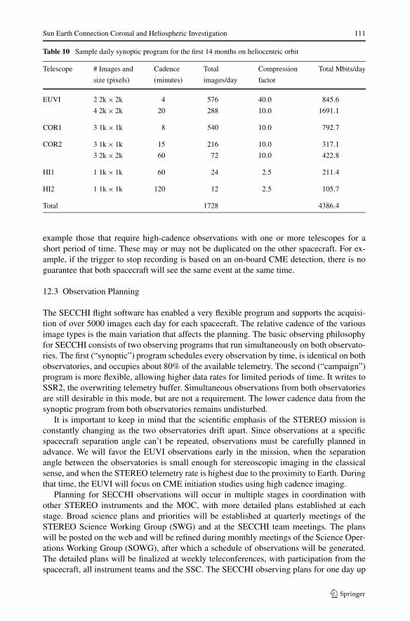
Sun Earth Connection Coronal and Heliospheric Investigation 111
Table 10 Sample daily synoptic program for the first 14 months on heliocentric orbit
Telescope # Images and Cadence Total Compression Total Mbits/day
size (pixels) (minutes) images/day factor
EUVI 2 2k × 2k 4 576 40.0 845.6
4 2k × 2k 20 288 10.0 1691.1
COR1 3 1k × 1k 8 540 10.0 792.7
COR2 3 1k × 1k 15 216 10.0 317.1
3 2k × 2k 60 72 10.0 422.8
HI1 1 1k × 1k 60 24 2.5 211.4
HI2 1 1k × 1k 120 12 2.5 105.7
Total 1728 4386.4
example those that require high-cadence observations with one or more telescopes for ashort period of time. These may or may not be duplicated on the other spacecraft. For ex-ample, if the trigger to stop recording is based on an on-board CME detection, there is noguarantee that both spacecraft will see the same event at the same time.
12.3 Observation Planning
The SECCHI flight software has enabled a very flexible program and supports the acquisi-tion of over 5000 images each day for each spacecraft. The relative cadence of the variousimage types is the main variation that affects the planning. The basic observing philosophyfor SECCHI consists of two observing programs that run simultaneously on both observato-ries. The first (“synoptic”) program schedules every observation by time, is identical on bothobservatories, and occupies about 80% of the available telemetry. The second (“campaign”)program is more flexible, allowing higher data rates for limited periods of time. It writes toSSR2, the overwriting telemetry buffer. Simultaneous observations from both observatoriesare still desirable in this mode, but are not a requirement. The lower cadence data from thesynoptic program from both observatories remains undisturbed.
It is important to keep in mind that the scientific emphasis of the STEREO mission isconstantly changing as the two observatories drift apart. Since observations at a specificspacecraft separation angle can’t be repeated, observations must be carefully planned inadvance. We will favor the EUVI observations early in the mission, when the separationangle between the observatories is small enough for stereoscopic imaging in the classicalsense, and when the STEREO telemetry rate is highest due to the proximity to Earth. Duringthat time, the EUVI will focus on CME initiation studies using high cadence imaging.
Planning for SECCHI observations will occur in multiple stages in coordination withother STEREO instruments and the MOC, with more detailed plans established at eachstage. Broad science plans and priorities will be established at quarterly meetings of theSTEREO Science Working Group (SWG) and at the SECCHI team meetings. The planswill be posted on the web and will be refined during monthly meetings of the Science Oper-ations Working Group (SOWG), after which a schedule of observations will be generated.The detailed plans will be finalized at weekly teleconferences, with participation from thespacecraft, all instrument teams and the SSC. The SECCHI observing plans for one day up

112 R.A. Howard et al.
to a week will be generated using the SECCHI Planning Tool. This tool is a set of InteractiveData Language (IDL) procedures that provides a graphical user interface to allow the oper-ator to generate a file of schedule commands for both spacecraft to be sent to the MOC viathe ITOS software. The planning tool performs constraint checking (for example, a warningis generated if simultaneous readouts from two CCDs controlled from the same CEB arescheduled), and monitors both internal buffer space and telemetry usage for each telescope.It is based on a similar tool that has been used in planning LASCO and EIT observationson the SOHO mission for over 10 years. The planned schedule can be displayed on the Webboth in graphical format and as a text file.
12.4 Beacon Mode
SECCHI space weather data will be broadcast continuously at a rate of 504 bps over thebeacon channel. These data will consist of a subset of images from each telescope. In orderto fit within the low bandwidth, the images need to be highly compressed, probably binnedto a low spatial resolution, as well as a subset of event messages that can be used to monitorinstrument status outside of the regular track periods. The exact compression techniqueswill be determined after launch. The SSC is responsible for collecting these data from thevarious ground stations that receive them, processing the data and serving them on the Web.
12.5 SECCHI Campaigns
For two or more periods totaling four weeks during the mission, there will be an additionaltrack, beginning 12 hours after the start of the normal daily track. The effect of this additionaltrack is to double the amount of telemetry that SECCHI is able to downlink each day. These‘SECCHI Campaigns’ will enable high-cadence observations targeted to specific scienceobjectives.
12.6 Routine Processing and Data Products
Routine processing of SECCHI data will take place at the POC (for real-time and socketplayback data) and at the SECCHI Data Processing Facility (DPF, for Level-0 packet files)at NRL. Science data will be processed into FITS files, consisting of a binary data arraypreceded by a header, with one file per image. No calibrations will be applied to the dataduring routine processing, and the resulting FITS file will be referred to as Level-0.5. FITSfiles generated from real-time data are referred to as ‘quick-look’. FITS files generated fromsocket playback or Level-0 files will be referred to as ‘preliminary’. When the final Level-0files are available from the MOC after 30 days, the resulting FITS files will be referred toas ‘final’. All final Level-0.5 FITS files will be archived at NRL, and will also be deliveredelectronically to the SSC and to Co-Investigator institutions. Processing of data to Level-1and higher levels will be done by individual users, using IDL routines and auxiliary datathat will be freely distributed as part of the SolarSoft software library and database. Somehigher level data products, such as polarized brightness images from COR1 and COR2,and Carrington maps, will be generated routinely by the DPF. Additional data products,including browse images, movies, lists of events such as CMEs and comets, housekeepingtables and long-term trending plots of key instrument performance parameters will also begenerated routinely and made available electronically.

Sun Earth Connection Coronal and Heliospheric Investigation 113
12.7 SECCHI Data Policy
The SECCHI data policy is to have completely open access to all data, including the cal-ibration data and procedures necessary to calibrate and process the data to higher levels.SECCHI images will be available as soon as the routine processing steps have been com-pleted. This is estimated to be within 30 minutes of receipt of all data necessary to form animage. The image data will be accessible via the Web using a searchable database. It willbe possible to generate queries to select and download data of interest using FITS headerkeywords as parameters. Temperatures, voltages, and other housekeeping parameters willalso be accessible through database queries.
Acknowledgements We gratefully acknowledge the hard work and dedication of the literally hundreds ofpeople who contributed to the SECCHI program. The SECCHI instrument was constructed by a consortiumof institutions: the Naval Research Laboratory (NRL, Washington, DC, USA), the Lockheed Martin Solar andAstrophysical Laboratory (LMSAL, Palo Alto, CA, USA), the NASA Goddard Space Flight Center (GSFC,Greenbelt, MD, USA), the Max Planck Institüt für Sonnensystemforschung (MPS, Lindau, Germany), theCentre Spatial de Liege (CSL, Angleur, Belgium), the University of Birmingham (UB, Birmingham, UK),the Rutherford Appleton Laboratory (RAL, Didcot, UK), the Institut d’Optique (IOTA, Orsay, France), theInstitute d’Astrophysique Spatiale (IAS, Orsay, France).
NRL is the lead institution in the consortium and was responsible for the supplying the COR2 corona-graph, the experiment electronics, the CCDs and focal plane assemblies, the flight and ground software, theintegration and testing of the instrument and the overall program management. LMSAL was responsible forproviding the EUVI telescope, the GT, the mechanism electronics box and mechanisms for the COR1, COR2and EUVI shutters and wheels. The GSFC was responsible for providing the COR1 telescope.
The USA effort was supported by the NASA Solar Terrestrial Physics STEREO Program under DPRS-13631-Y. The program managers at GSFC were Abby Harper, Haydee Moldanado and for the last 3 yearsof the program, Nicholas Chrissotimos. The program manager for instruments was Michael Delmont and theSECCHI instrument manager was Bernie Klein. We are indebted to their efforts and to those of the othermembers of the STEREO project. The NRL effort was also supported by the USAF Space Test Program andthe Office of Naval Research.
At NRL, the COR2 subsystem design, fabrication and testing was done by Dennis Socker, Simon Plun-kett, Angelos Vourlidas, Clarence Korendyke, Edward Shepler, Jeff Morrill of NRL, Qian Gong, RobertHagood, Paul Nikulla and Pete Patterson of Swales, Inc, Martin Koomen of Sachs-Freeman, Robert Moye,David Roberts, Arnaud Thernisien and Robin Colaninno of Artec and Marc Westcott of Tropel. The FPA wasdesigned and tested by Benjamin Au of Praxis, Dan Moses, Jeffrey Newmark of NRL, and Paul Nikulla andMiles Newman of Swales. The FPAs were fabricated at the University of Birmingham by Chris Eyles, CliveLongstaff, and John Bryant. The CCDs were procured from e2V and were calibrated by Richard Kroegerof NRL. The SEB hardware was designed and tested by Sean Lynch, Robert Skalitzky and Amy Hurley ofNRL, Drew Roberts, Greg Clifford, and Dennis Silver of Silver Engineering, Inc., and Dale Bankus of OSC.The SEB flight software was designed and developed by Dennis Wang of Interferometrics, Inc., and LaddWheeler and Joel Chiralo of the Hammers Company and Matthew Hayden of NRL. The harness was de-signed and built by Susie LaCava, James (Chris) Garner, and Richard Cooksey of NRL and Ralph Hopkinsof Honeywell. The SCIP door design and testing was supported by Stephen Koss and Paul Oppenheimer ofNRL. The SECCHI environmental testing was performed by Michael VanHerpe, Robert Haynes and MichaelObara of NRL. Contamination control support was provided by Therese Errigo, Radford Perry and AndrewUhl of Swales Inc. Configuration management was provided by John Tota, Nick Virmani, Ken Slocum, StuSweitzer of Swales. SECCHI project management was provided by Rebecca Baugh, Donald McMullin andDale Harris of Praxis, Inc. System engineering was provided by Timothy Carter and Benjamin Au of Praxisand James Garner of NRL. The SCIP thermal design was performed by Miles Newman of Swales.
At LMSAL, the EUVI and GT telescopes were designed, fabricated, and tested by James Lemen, Jean-Pierre Wuelser, Jacob Wolfson, Glenn Gradwohl, Theodore Tarbell, Joseph Cannon, Noah Katz, DunaganPearson. The mechanisms were designed and built by Augustus Moore and David Akin. The MEB and GTelectronics were designed by Larry Springer, George Rossi and Russell Lindgren. Contamination supportwas provided by Syndie Meyers and thermal support by Rose Deguzman. Program management was done byDexter Duncan, Larry Springer and Frank Friedlaender. Configuration management and system engineeringsupport was performed by Brock Carpenter and Claude Kam.
At GSFC, the COR1 was designed, fabricated and tested by Joseph Davila, Eric Mentzell, Kim Mehalik,Julie Crooke, Rebecca Derro, Chris St Cyr, William Thompson of GSFC and Michael Hersh and Miles

114 R.A. Howard et al.
Newman of Swales. Program management was performed by Lawrence Orwig and system engineering byRichard Wiesenberg.
The German science and hardware contributions to SECCHI—the project STEREO/Corona—is sup-ported by the German “Bundesministerium für Bildung und Forschung” through the “Deutsche Zentrumfür Luft- und Raumfahrt e.V.” (DLR, German Space Agency). The Max-Planck-Institute für Sonnensystem-forschung supplied the aperture doors for the SCIP telescopes.
The UK contribution to STEREO was funded by the Particle Physics and Astronomy Research Council(PPARC) and we also acknowledge significant support for the Heliosphere Imager from the School of Physicsand Astronomy, University of Birmingham. The HI and CEB program management was led by RichardHarrison and James Lang at RAL. At the University of Birmingham, the HI design, fabrication and testingwas performed by Christopher Eyles, CEB hardware was designed by Nick Waltham, James King, AndrewMarshall and Matthew Clapp. The CEB software was developed by Duncan Drummond and John Rainnie.The CEBs were fabricated and tested at the University of Birmingham by Chris Eyles, John Bryant and DavidSmith. The HI thermal design was performed by Helen Mapson-Menard initially and completed by BryanShaughnessy of RAL.
The French teams were supported by the Centre National d’Etudes Spatiales and the Centre National dela Recherche Scientifique. At IOTA, the design and fabrication of the EUVI multilayers was performed byMarie-Françoise Ravet, Françoise Bridou, Franck Delmotte and Arnaud Jerome and the polishing/figuringof the EUVI mirrors was performed by Jean-Yves Clotaire, Gilles Colas, Michel Lamare, Raymond Mercierand Michel Mullot. The testing and calibration of the multilayer mirror performance was performed at IASby Jean-Pierre Delaboudiniere, Frederic Auchere, Philippe Bouyries and Xueyan Song.
The Belgian effort was supported by the Belgian Science Policy Office. The HI optical design, environ-mental testing and calibration (stray-light and photometric) was performed at Centre Spatial de Liege byJean-Marc Defise, Jean-Philippe Halain, Emmanuel Mazy, Philippe Ronchain and Pierre Rochus.
References
D. Akin, R. Horber, C.J. Wolfson, Three high duty cycle, space-qualified mechanisms, in NASA Conf. Pub.,vol. 3205 (1993)
G.E. Brueckner, R.A. Howard, M.J. Koomen, C.M. Korendyke, D.J. Michels, J.D. Moses, D.G. Socker, K.P.Dere, P.L. Lamy, A. Llebaria, M.V. Bout, R. Schwenn, G.M. Simnett, D.K. Bedford, C.J. Eyles, SolarPhys. 162, 357–402 (1995)
A. Buffington, B.V. Jackson, C.M. Korendyke, Appl. Opt. 35, 6669–6673 (1996)K.P. Dere, E. Landi, H.E. Mason, B.C. Monsignori Fossi, P.R. Young, CHIANTI—an atomic database for
emission lines. Astron. Astrophys. Suppl. Ser. 125, 149 (1997)J.M. Defise, J.P. Halain, E. Mazy, P. Rochus, R.A. Howard, J.D. Moses, D.G. Socker, R.A. Harrison,
G.M. Simnett, Design and tests for the heliospheric imager of the STEREO mission, in InnovativeTelescopes and Instrumentation for Solar Astrophysics, ed. by S.L. Keil, S.V. Avakyan. Proc. SPIE,vol. 4853 (SPIE, Bellington, 2003), pp. 12–22
J.P. Delaboudinière et al., EIT: extreme-ultraviolet imaging telescope for the SOHO mission. Sol. Phys. 162,291–312 (1995)
C.J. Eyles, G.M. Simnett, M.P. Cooke, B.V. Jackson, A. Buffington, P.P. Hick, N.R. Waltham, J.M. King,P.A. Anderson, P.E. Holladay, Sol. Phys. 217, 319–347 (2003)
E.G. Gibson, The Quiet Sun, SP-303, National Aeronautics and Space Administration (1973)B.N. Handy et al., The transition region and coronal explorer. Sol. Phys. 187, 229–260 (1999)R.A. Harrison, C.J. Davis, C.J. Eyles, The STEREO heliospheric imager: how to detect CMEs in the he-
liosphere. Adv. Space Res. 36, 1512–1523 (2005)R.A. Howard, Historical perspective on coronal mass ejections, in Solar Eruptions and Energetic Particles,
ed. by N. Gopalswamy. Geophysical Monograph Series, vol. 165 (American Geophysical Union, Wash-ington, 2006), pp. 7–13
R.A. Howard, J.D. Moses, D.G. Socker, the SECCHI consortium, Sun-Earth connection coronal and he-liospheric investigation (SECCHI), in Instrumentation for UV/EUV Astronomy and Solar Missions,vol. 4139, ed. by S. Fineschi, C.M. Korendyke, O.H. Siegmund, B.E. Woodgate (SPIE, Bellingham,2000), pp. 259–283
B. Lyot, The study of the solar corona and prominences without eclipses (George Darwin Lecture, 1939).Mon. Not. R. Astron. Soc. 99, 580–594 (1939)
J.S. Morrill et al., Calibration of the SOHO/LASCO C3 white light coronagraph. Sol. Phys. 233, 331–372(2006)

Sun Earth Connection Coronal and Heliospheric Investigation 115
E. Pitz, C. Leinert, H. Link, N. Salm, HELIOS zodiacal light experiment, in Interplanetary Dust and ZodiacalLight. IAU Colloq., vol. 31 (Cambridge University Press, Cambridge, 1976), pp. 19–23
M.F. Ravet, F. Bridou, X. Zhang-Song, A. Jerome, F. Delmotte, M. Bougnet, J.P. Delaboudinière, Ion beamdeposited Mo/Si multilayers for EUV imaging applications in astrophysics. Proc. SPIE 5250 (2003)
K. Saito, A.I. Poland, R.H. Munro, A study of the background corona near solar minimum. Sol. Phys. 55,121–134 (1977)
D.G. Socker, R.A. Howard, C.M. Korendyke, G.M. Simnett, D.F. Webb, The NASA solar terrestrial relationsobservatory (STEREO) mission heliospheric imager, in Instrumentation for UV/EUV Astronomy andSolar Missions, vol. 4139, ed. by S. Fineschi, C.M. Korendyke, O.H. Siegmund, B.E. Woodgate (SPIE,Bellingham, 2000), pp. 284–293
R.A. Stern, the SXI Team, Solar X-ray imager for GOES. Proc. SPIE 5171 (2003)K. Strong, T. Bruner, M. Tarbell, A. Title, C. Wolfson, TRACE—the transition region and coronal explorer.
Space Sci. Rev. 70, 119 (1994)S.J. Tappin, A. Buffington, M.P. Cooke, C.J. Eyles, P.P. Hick, P.E. Holladay, B.V. Jackson, J.C. Johnston, T.
Kuchar, D. Mizuno, J.B. Mozer, S. Price, R.R. Radick, G.M. Simnett, D. Sinclair, N.R. Waltham, D.F.Webb, Geophys. Res. Lett. 31, L02802 (2003). doi:10.1029/2003GL018766
W.T. Thompson, J.M. Davila, R.R. Fisher, L.E. Orwig, J.E. Mentzell, S.E. Hetherington, R.J. Derro, R.E. Fed-erline, D.C. Clark, P.T.C. Chen, J.L. Tveekrem, A.J. Martino, J. Novello, R.P. Wesenberg, O.C. St Cyr,N.L. Reginald, R.A. Howard, K.I. Mehalick, M.J. Hersh, M.D. Newman, D.L. Thomas, G.L. Card, D.F.Elmore, COR1 inner coronagraph for STEREO-SECCHI, in Innovative Telescopes and Instrumentationfor Solar Astrophysics, ed. by S.L. Keil, S.V. Avakyan. Proc. SPIE, vol. 4853 (SPIE, Bellingham, 2003),pp. 1–11
D.L. Windt, R.C. Catura, Multilayer characterization at LPARL. Proc. SPIE 984, 132–139 (1988)J.-P. Wülser et al., EUVI: the STEREO-SECCHI extreme ultraviolet imager. Proc. SPIE 5171 (2003)P.R. Young, G. Del Zanna, E. Landi, K.P. Dere, H.E. Mason, M. Landini, CHIANTI—an atomic database for
emission lines. Astrophys. J. Suppl. Ser. 144, 135–152 (2003)