summary report on laser surface preparation of composite ... · pdf filesummary report on...
TRANSCRIPT

www.lasertronics.com
1
Summary Report on Laser Surface Preparation of Composite Material March 31, 2014
Reference: Air Force Research Laboratory SBIR Project AF121-120 – Phase 1 Subject: Testing Results for Laser Surface Preparation of Composites 1. Executive Summary: General Lasertronics Corporation (Lasertronics) completed this Small Business Innovation Research (SBIR) project in March, 2013. The research examined the degree to which laser surface preparation of composite material enhanced the repeatability and fracture toughness of adhesive bonds, compared with conventional abrasive-plus-solvent wipe processes. Lasertronics designs and manufactures specialized laser systems for coating removal and surface preparation. Lasertronics’ systems incorporate unique closed-loop, real-time electronic control technology that provides a precise, repeatable distribution of laser energy on the target surface, while protecting the substrate from any changes in material properties. Lasertronics began investigating laser composite surface preparation in 2006, the objective being to improve repeatability of adhesive bonding processes for aerospace composites. Lasertronics developed specific laser parameters for surface prep, including wavelength, fluence, irradiance, and pulse duration, that enhanced the adhesion of coatings to composites. Coatings applied to laser-processed bismaleimide (BMI) carbon fiber reinforced polymer (CFRP) samples demonstrated coating adhesion values much more repeatable than coatings applied to conventionally prepared surfaces. Double cantilever beam (DCB) tests confirmed that laser preparation also produces highly repeatable bond toughness (G1C) values with superior fracture mode behavior. (DCB testing and G1C are explained in Technical Notes on page 8). This SBIR project was a rigorous follow-up to those preliminary observations. Its primary objective was to quantify the degree to which laser surface preparation improves repeatability of adhesive bond properties in an industry-standard aircraft composite, IM7/5250-4 laminates joined with AF-191 epoxy, cured at 350°F. The adhesive bond properties achieved with laser-prepared samples were compared to bonds produced by conventional manual-abrasive-with-solvent-wipe processes. The test matrix included surface energy measurements, DCB bond toughness tests, and electron microscopic analysis of test samples. Conclusions: Compared to conventional baseline processes, the laser-prepared samples exhibited:
• Greater than 2X improvement in repeatability of the bonding process outcome. • Higher G1C values, indicating improved bond fracture toughness. • Uniformly excellent DCB fracture mode behavior: no adhesive failures. • Demonstrated compatibility with conventional automation strategies; the laser process
is scalable to airframe manufacturing throughput requirements. Each of these results is significant in the context of manufacturing composite airframes and components. Taken together, they arguably represent a breakthrough.

www.lasertronics.com
2
CONTENTS: 1. Executive Summary, page 1 2. Technical Background, page 2 3. Project Objective, page 2 4. Laser Process Physics, page 2 5. Surface Energy Testing, page 4 6. DCB Testing, page 5 7. DCB Test Results, page 7 8. Conclusions, page 8 9. Technical Notes, page 8
2. Technical Background: For a discussion of why composites are used in aircraft, see Technical Note 1 on page 8. Reliable adhesive bonding of organic matrix composites (OMCs, hereinafter referred to as composites) requires effective, repeatable surface preparation. Current surface preparation methods include sacrificial peel-ply layers, grit blasting, and manually-applied abrasives, typically followed by solvent wiping. These high-labor content processes inherently deliver variable outcomes. They can damage the outermost reinforcing fibers in the composite substrate, and they all produce significant waste streams. Finally, abrasive processes are not consistently effective in removing significant contaminants, such as mold release agents and hydrocarbons, from the faying surfaces of adhesive joints. The presence of contaminants degrades bond repeatability. 3. Project Objective: The primary objective of this SBIR project was to quantify the degree to which laser surface preparation can improve repeatability of adhesive bond properties in bonded joints between high-performance BMI composite (IM7/5250-4) laminates joined with 350°F-cure AF-191 epoxy), while maintaining or improving baseline bond toughness. Using DCB tests (explained in Technical Note 2 on page 8), bonds made with laser-prepared test samples were compared to otherwise identical samples and bonds prepared with an aircraft manufacturer’s baseline manual abrasive surface preparation process. A secondary objective was to demonstrate an automated laser surface preparation process for composites that could be scaled up for real-world airframe manufacturing applications. 4. Laser Process Physics: The ablative effects of laser radiation on the surface of a composite material are fundamentally different from the mechanical effects of peel ply removal, grit blasting or sanding. The laser ablation process is shown schematically in Figure 1, below.
The two primary parameters that drive ablation at the material surface are:
1.) Laser irradiance, which is the energy rate per unit area (Joules / sec / cm2), and
2.) Laser fluence, which is the total energy per unit area (Joules / cm2). Irradiance multiplied by exposure time equals fluence.
A secondary parameter is the reactive gas environment at the surface.

www.lasertronics.com
3
The plasma dynamics, thermochemistry, and thermal radiation events at the surface “photoablate” (vaporize) contaminants, adsorbate films, and an extremely thin (several millionths of a meter) layer of the composite’s resin matrix phase. Extremely short laser pulse duration (shorter than 200 nanoseconds) effectively controls any heat conduction into the substrate. Lasertronics’ systems deliver high-power, short-duration pulses of laser energy, with real-time closed-loop controls that accurately regulate the spatial distribution of laser energy delivered to the surface.
FIGURE 1 – Schematic Diagram of Laser Physics Directed laser energy acts much as a “photonic peel ply”, and eliminates the need for chemicals, abrasives, or blast media for surface preparation. The laser energy converts most of the photoablated mass into a gaseous-phase effluent. The residual particulate waste stream is typically less than 50% of the mass of the material removed. Particulate waste is efficiently captured by a vacuum waste collection system and sequestered in a paper HEPA filter. This is the entire waste stream. Thus, laser photoablation inherently minimizes the environmental, health, and safety problems associated with composite surface preparation. In order to produce a controlled, repeatable laser ablation process that does not damage the composite substrate, the target material must fully absorb the laser energy in a shallow surface layer, to prevent penetration deep into the substrate. Understanding the optical absorption characteristics of the matrix phase material is a key consideration in designing a controlled, repeatable laser process for composite materials. Lasertronics discovered that a short-wave laser pulse with high irradiance and short duration is readily absorbed by the matrix-phase material in various types of composites. This absorption characteristic protects the reinforcing fibers and makes this laser process ideal for composite surface preparation applications. Any laser energy that may penetrate into the composite matrix phase is partially absorbed in the composite material. Experience with different types of composites confirms the ability of carbon fibers to absorb moderate energy levels without adverse effects. Heat conduction in composites is highly anisotropic - typically five to ten times greater in the longitudinal (axial) direction than in the through-thickness direction. This characteristic allows the material to function as an efficient heat sink to dissipate any energy absorbed.
Carbon Fiber Substrate
Resin Layer
Laser Irradiance
Gaseous & Particulate Ejecta
Ablation Process
Sonic Expansion Wave

www.lasertronics.com
4
Scanning electron microscopy (SEM) of laser-processed samples confirms that the short-wave laser process photoablates composite substrates to a depth of 3 to 5 microns (µm). This “photonic peel-ply” process removes an extremely thin layer of matrix material, while leaving the carbon or glass reinforcing fibers unaffected. However, the laser has unique advantages over peel ply:
• The laser covers the entire surface uniformly. • The laser does not produce broken fibers or panel curvature. • The laser is a robotic process that essentially eliminates touch labor. • The laser produces almost zero waste material. • The laser chemically functionalizes the surface. • The laser can be configured for automated, real-time acquisition of parametric data
from the manufacturing process; this enables accurate analysis of digital process control metrics to facilitate quality protocols such as Six-Sigma, SPC, etc.
These advantages enable the laser process to deliver superior repeatability in the bonding process and in related outcomes. This assures a highly-controlled manufacturing process with consistent outcomes.
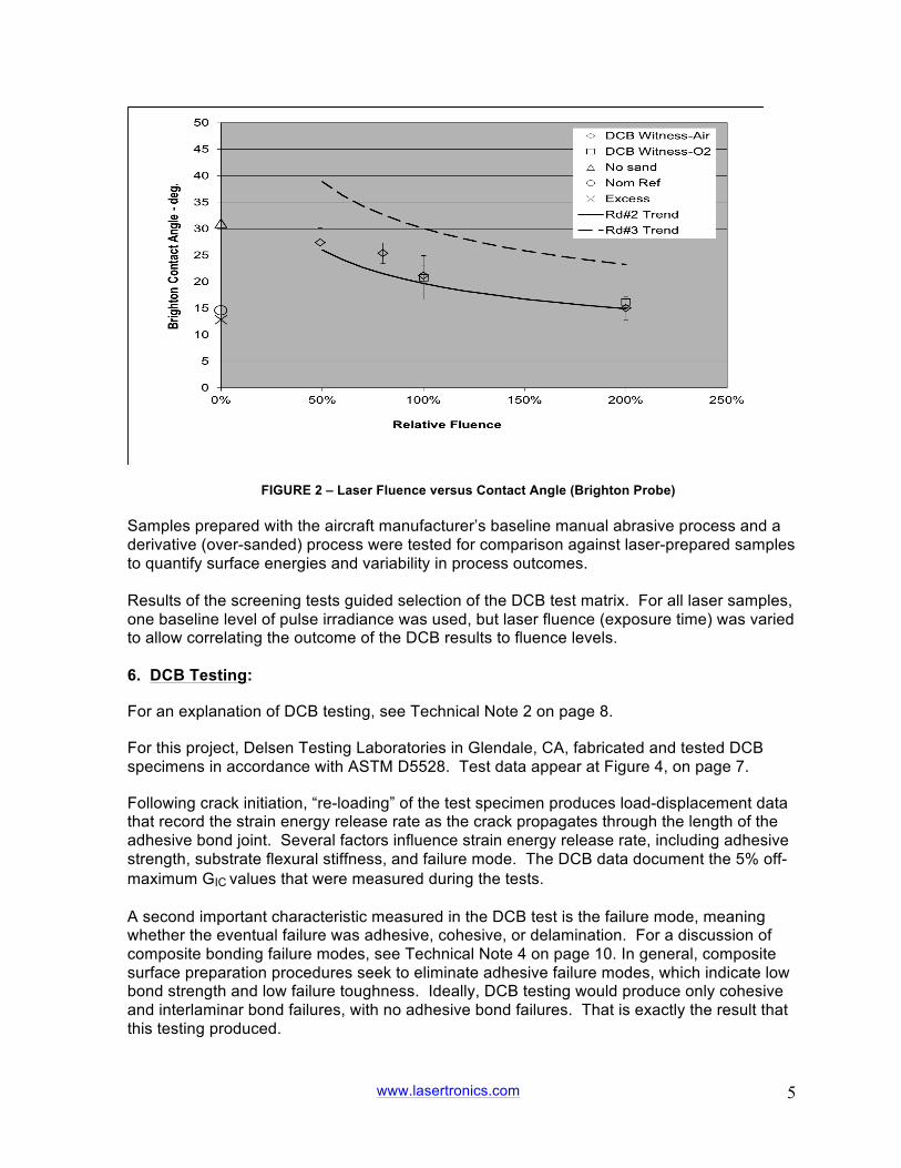
Detailed SEM analysis of laser-processed samples confirms that the laser does not ablate or damage carbon fibers while photoablating the surface of the matrix-phase resin material. The shallow extinction depth of the laser enables highly repeatable laser effects with tight six-sigma process metrics. The laser is a non-contact, directed-energy process, so it is inherently compatible with conventional automation strategies. Laser ablation increases the repeatability of the process outcome while substantially reducing touch labor and nearly eliminating waste. For example, a robotic laser system is currently in use at the US Navy’s Fleet Readiness Center-East to remove paint coatings from main rotor blades of CH-53E helicopters. The Navy expects to extend the process to include H-60 and V-22 rotor blades as well. 5. Surface Energy Testing: Surface energy is a recognized measure of a material’s receptivity to coatings and adhesives. For this project, screening tests using a Brighton Probe instrument to measure sessile-drop contact angle evaluated the effects of different laser processing conditions on the surface energy of the composite material used in this project. For a discussion of surface energy and sessile-drop testing, see Technical Note 3 on page 9. For this project, three rounds of surface energy screening tests including 111 samples were performed to assess the impact of laser surface preparation. An important result was the monotonic correlation between laser fluence (total energy per unit area) and contact angle (see Figure 2, below): Higher laser fluence levels directly correlated with lower contact angles and better wetting characteristics. These data show that short-wave laser surface preparation measurably improves the surface energy values of the composite material. Higher surface energy values typically correlate with improved coating adhesion.
www.lasertronics.com
5
FIGURE 2 – Laser Fluence versus Contact Angle (Brighton Probe) Samples prepared with the aircraft manufacturer’s baseline manual abrasive process and a derivative (over-sanded) process were tested for comparison against laser-prepared samples to quantify surface energies and variability in process outcomes. Results of the screening tests guided selection of the DCB test matrix. For all laser samples, one baseline level of pulse irradiance was used, but laser fluence (exposure time) was varied to allow correlating the outcome of the DCB results to fluence levels. 6. DCB Testing:
For an explanation of DCB testing, see Technical Note 2 on page 8.
For this project, Delsen Testing Laboratories in Glendale, CA, fabricated and tested DCB specimens in accordance with ASTM D5528. Test data appear at Figure 4, on page 7.
Following crack initiation, “re-loading” of the test specimen produces load-displacement data that record the strain energy release rate as the crack propagates through the length of the adhesive bond joint. Several factors influence strain energy release rate, including adhesive strength, substrate flexural stiffness, and failure mode. The DCB data document the 5% off-maximum GIC values that were measured during the tests. A second important characteristic measured in the DCB test is the failure mode, meaning whether the eventual failure was adhesive, cohesive, or delamination. For a discussion of composite bonding failure modes, see Technical Note 4 on page 10. In general, composite surface preparation procedures seek to eliminate adhesive failure modes, which indicate low bond strength and low failure toughness. Ideally, DCB testing would produce only cohesive and interlaminar bond failures, with no adhesive bond failures. That is exactly the result that this testing produced.

www.lasertronics.com
6
In addition to fabricating and testing DCB specimens, Delsen Laboratories also analyzed the DCB load-displacement data and the failure mode area ratios of the test specimens. A photograph of DCB failure surfaces is shown in Figure 3, below:
FIGURE 3 – DCB Failure Surfaces with Cohesive and Mixed Cohesive-Interlaminar Modes The DCB data in Figure 4 show a monotonic correlation of higher GIC values with higher laser fluence.. Furthermore, higher laser fluence levels reduced the variability of GIC values, as measured by the standard deviation and coefficient of variance (Cv) in the DCB test sample populations that were processed with the two higher-fluence laser conditions. The 100% fluence condition corresponds to a laser scan pattern with the minimum overlap of laser-illuminated spots necessary to assure full coverage of the target surface with laser illumination. Samples prepared with the 100% laser fluence condition showed 85-90% cohesive failures, with the rest interlaminar. The 200% fluence condition incorporates twice the fluence level of the 100% condition. Delsen Laboratories’ analysis showed that samples prepared with the 200% laser fluence condition showed 90-100% cohesive failures, and the rest interlaminar. At the 200% laser fluence condition DCB tests with air and oxygen purge produced results equivalent to values obtained in construction of the F-22 aircraft, widely regarded as the apex to date for composite bonding (Melcher et.al.). Significantly, there were no adhesive failures in samples processed with either the 100% or 200% laser conditions. The 100% fluence level appears to be the threshold laser condition for effective surface preparation. Laser conditions at lower fluence levels - 80% and 50% - produced low G1C values with mostly adhesive-mode failures. At these lower process conditions, the laser does

www.lasertronics.com
7
not treat the entire surface. Lower adhesive bond toughness values reflect this incomplete bond joint coverage. 7. DCB Test Results: DCB test data for the aircraft manufacturer’s baseline surface preparation process showed high variability, as was expected from a manual procedure. In addition to the higher variability in the manual abrasive process outcomes, SEM and optical microscopy also showed that manual abrasive processes consistently damaged the near-surface carbon fibers of the test substrates. This damage is undesirable, and stands in contrast to the laser-processed samples, which showed no damage of any kind to the carbon fibers. DCB test results across the populations of laser-processed and baseline manual abrasive- processed samples show: • The measured G1C values from the high-fluence laser process had a coefficient of variance
(CV) value less than half that of the baseline manual abrasive process. So, the laser-processed samples had much greater repeatability than their baseline counterparts.
• The measured G1C values for the high-fluence laser process were highest of any test population, including the baseline manual abrasive process. So, the laser-processed samples showed greater bond fracture toughness than their baseline counterparts.
These improvements are very significant for composite manufacturing applications.
Initial Test Data Reload Test Data
Failure Mode
DCB
Specimens
Description
5%off Max
Std Dev
Coeff of Var %
Max
Load (#)
5%off Max
Std dev
Cohesive
Adhesive
Interlaminar
10 200% laser fluence
13.97 1.25 9 82.8 10.48 1.019 90 to 100% <10%
8 100% laser fluence
12.46 1.64 13 74.1 10.23 0.643 85 to 90% 10 to 15%
10 80% laser fluence
8.98 2.41 27 75.3 2.2 1.037 <10% 95 to 100%
10 50% laser fluence
10.40 2.41 23 76.2 4.78 1.669 <10% 96 to 100%
10 200% laser fluence (O2 - see Note 1)
14.14 1.18 8 83.0 9.79 1.604 50 to 90% 10 to 60% 5 to 10 %
9 Nominal laser fluence (O2 – see
Note 1)
11.75 2.42 21 78.4 3.51 3.342 0 to 8% 80 to 100% <5%
10 Baseline sanding process
6.82 1.56 23 61.8 5.33 1.393 3 to 18% 80 to 95% <5%
9 Wet chem clean – no sanding (see Note 2)
13.90 2.64 19 83.3 10.32 1.258 85 to 95% <10% 5 to 20 %
10 Excessive sanding
11.52 2.16 19 80.3 9.39 1.63 40 to 85% 10 to 50% 5 to 12 %
FIGURE 4 – Tabular Summary of DCB Test Data Notes: 1. Two rounds of laser surface prep were performed in a pure oxygen environment to determine whether
oxygen partial pressure at the substrate surface during laser ablation would influence the DCB results. 2. This process used for testing only, and is not for production use.

www.lasertronics.com
8
8. Conclusions: 1. Laser surface preparation, using the appropriate laser recipe and closed-loop control, can
bring significant improvement to the consistent repeatability of both: a. the process of bonding composites together, and b. the outcomes of that process, principally manifest in much more consistent bond
performance. Measures include higher G1C values, complete elimination of adhesive failures, and greater than 2X improvement in outcome repeatability.
2. Laser processes are inherently scalable and compatible with various modes of factory
automation. This compatibility would enable greater throughput and tighter control than conventional methods of composite surface preparation.
9. Technical Notes:
1. Why Composites Are Used In Aircraft: Organic matrix composites (“OMCs” or simply “composites”) are used extensively in military aircraft and next-generation commercial aircraft because of their high specific modulus (stiffness per unit weight), strength properties, and ability to be fabricated in structurally-efficient airframe configurations. Airframe structures incorporating composites achieve higher strength-to-weight ratios than those of conventional airframe materials, with related performance advantages. Composite airframe materials have also demonstrated excellent corrosion resistance and mechanical toughness in military and commercial airframes, with attendant lower life-cycle costs. Replacing mechanically-joined metal airframe structures with adhesively-bonded composite assemblies reduces weight, parts count, direct labor costs, fastener costs, and the need for recurring inspections and repairs related to fastener penetrations in the airframe structure. Realization of these potential benefits, however, requires that the adhesive bonding process for composite airframe structures consistently produce reliable bonded joints with predictable mechanical properties. Achieving this consistent repeatability in bonds between composite surfaces has proved elusive using conventional surface preparation techniques – peel ply, grit blasting, and sanding, followed by solvent wipe. 2. Double Cantilever Beam (“DCB”) Testing: The failure toughness of bonded joints can be quantified by measurements of failure mechanics-based bond properties. Evaluation of different surface preparation methods in this project was based on DCB tests per ASTM specification D5528, “Standard Test Method for Mode 1 Interlaminar Fracture Toughness of Unidirectional Fiber-Reinforced Polymer Matrix Composites”. The DCB test defined in ASTM D5528 measures the critical value of the Mode-1 strain energy release rate (G1C) as an induced crack propagates through the plane of the adhesive joint between the faying surfaces of the bonded joint specimen. G1C values measure adhesive bond failure toughness. The DCB tests also included analysis of the failure modes exhibited by the specimen surfaces (e.g., adhesive, cohesive, or interlaminar). Failure mode analysis provides key information about failure mechanisms and bond quality. DCB testing is designed to quantify the Mode-1 failure toughness of an adhesive bond by measuring the critical value (5% off-maximum) of the strain energy release rate (GIC) during the propagation of an induced crack through the plane of the adhesive bond between the faying surfaces of the two bonded substrates. Load blocks attached to each side of the DCB specimen provide attachment points to a tensile dynamometer that generates the mechanical

www.lasertronics.com
9
forces for the test. The standard D5528 test article is a 1” x 4” (25.4 mm x 101.6 mm) specimen with the zero-degree fiber orientation in the longitudinal axis of unidirectional composite substrates (see examples in Figure 3 on page 6). During the DCB test, crack initiation and propagation is achieved by the application of tensile loads through the load blocks, normal to the short-transverse direction of the adhesive bond line. These loads are identified as force P in the drawing at Figure 5, below. As the two bonded substrates are pulled apart, crack propagation occurs, and the force required to maintain propagation is recorded.
FIGURE 5 – ASTM D5528 Double Cantilever Beam (DCB) Specimen with Load Blocks 3. Sessile-Drop Contact Angle Testing: The sessile-drop test (from the Latin sessilis, “pertaining to sitting”) is an accepted method for measuring surface energy of a surface. The sessile drop test infers surface energy value by measuring the angle between the surface and the edge of the bead that forms when a droplet of the chosen probe liquid is placed on the surface to be investigated. This is called the contact angle. Contact angle indicates the surface energy balance between polar and dispersive forces in the liquid as it forms droplets after being applied to the test surface. A low contact angle, characteristic of a large footprint and low profile, indicates high surface energy, better adhesive wetting characteristics, and high receptivity to coatings, including adhesives. A near-vertical contact angle, characteristic of a small footprint and high profile, indicates low surface energy and poor receptivity to coatings. Each material has inherent characteristic degrees of receptivity to coatings. Surfaces that readily accept coatings are easier to paint or bond together with adhesives than surfaces that do not. Polymer surfaces typically do not readily accept coatings, which makes composites difficult to paint or bond with adhesives. A surface that is highly receptive to coatings will allow a liquid drop placed on it to spread out and occupy a large footprint. As a result of this spreading out, the droplet will exhibit a low profile (low contact angle) with the surface. Raindrops on a car that has not been waxed exhibit this behavior; they are flat, and barely recognizable as separate droplets. A surface that generates this large-footprint, low-profile droplet formation is referred to as a high-energy surface.

www.lasertronics.com
10
Conversely, a surface that is not receptive to coatings will characteristically prevent the same droplet from spreading out, causing it instead to occupy a small footprint and exhibit a higher profile (higher contact angle) with the surface. Picture raindrops beading on a waxed car hood; each drop is quite distinct and erect. This is referred to as a low-energy surface condition. For applying paints, sealants, or adhesives to a surface, a high-energy surface condition is obviously desirable. Some materials, including many composites, have characteristic surface energy so low that coatings adhere poorly. The sessile drop test was used to measure surface energy in this project. 4. Failure Modes of Bonds Between Composite Surfaces: Adhesively bonded joints between composites typically exhibit three primary fracture modes during DCB testing:
• Adhesive failure occurs when the adhesive disbonds from the composite surface under the test loads.
• Cohesive failure occurs when the adhesive itself fails under the test loads, despite residual adhesion to the bonded surfaces.
• Interlaminar failure occurs when the composite substrate material itself delaminates under the test loads.
Test specimens often exhibit a mixture of these three failure modes during DCB tests. In general, composite bonding procedures seek to eliminate adhesive failure modes, because this mode indicates adhesive bonds with low strength and low failure toughness. During DCB testing, cohesive and interlaminar failure modes are strongly preferred to adhesive-mode failures at the faying surfaces of the bond joint. The consensus among technical specialists is that bond failure mode exhibited during DCB testing provides critical information about the overall integrity and fracture toughness of the bond joint. 5. Equipment Required for the Surface Pretreatment Described Here: Lasertronics has perfected closed-loop electronic control systems and other laser-related technologies that enable use of lasers in applications that would otherwise be impractical. One of those applications is pre-treatment of composite surfaces to enhance coating adhesion, as described in this report. (Another application, not described here, is coating removal – paints, sealants, corrosion – from any part of an aluminum aircraft for maintenance or repair; the FAA expressed “No Objection” to this use in 2010.)
• System Integration: Lasertronics integrates its proprietary control technologies with industrial lasers made by any of several different laser manufacturers, selecting the laser that best meets the user’s needs. The resulting systems include the control system, laser(s), delivery tool(s), waste capture system, robotics when called for, and in some cases a chiller.
• Two Configurations: Broadly speaking, Lasertronics systems are available in two configurations: manual and robotically controlled.
• Manual systems employ a hand-held delivery tool designed to be moved over the relevant surface by a technician. These systems are intended for maintenance and repair work, where robotics would be impractical because no two jobs are identical. Several different delivery tools are available, each weighing about two pounds.
◦ In manual systems designed for removal of coatings (paints, sealants, corrosion), the delivery tool attaches to the laser and waste capture unit via an

www.lasertronics.com
11
umbilical cable 50 meters long. These delivery tools are light enough for the technician to move them over the relevant surface without mechanical assist. Pictured here is a typical system delivered several years ago:
www.lasertronics.com
Presidential Helicopter System
Lasertronics system installed at NAS Patuxent River, MD Next generation system will not require chiller (beige).
Laser cabinet (gray) will be ½ this size.
◦ In manual systems designed for surface treatment of composites, the required light wavelength precludes use of an umbilical cable, so the laser moves with the delivery tool. For repair work on aircraft, simple lift-assist devices would support the delivery tool, laser, and related control electronics, allowing the technician to precisely position the delivery tool for the needed repair.
• Robotic systems, used in production environments requiring repeated execution of identical processes, typically employ multiple lasers for maximum throughput of product. Lasertronics custom-designs these systems in collaboration with robotic system integrators. Robotic laser applications are common in automotive manufacturing, so these integrations are well understood. The lasers are physically small compared to the robot components. Waste capture and cooling occur remotely, connected to the laser via ducts and hoses. Pictured here is the Automated Rotor Blade Stripping System (ARBSS) installed at the Navy’s Fleet Readiness Center-East, Cherry Point, NC, where it strips CH-53 rotor blades.

www.lasertronics.com
12
www.lasertronics.com
Navy FRC-East ARBSS System
Automated Rotor Blade Stripping System
The white box at the end of the robot arm contains three laser delivery tools, related control optics, and waste capture intakes. The blue hoses bring laser power to the delivery tools. The brown hoses route captured particulate effluent to a HEPA filter. The black object under the white box is a CH-53 fiberglass composite rotor blade. A laser system for use in a manufacturing environment - for example, to surface-prep composite surfaces - would probably resemble ARBSS physically, and would incorporate lasers producing the appropriate wavelengths for that application.
• Infrastructure Required: Lasertronics systems are compatible with conventional electrical power found in factories and hangars. The nominal power requirement for the manual systems is 380 Volt, 3-phase, 35 amps. Lasertronics systems require no special enclosures, ventilation, or other provisions beyond opaque screening similar to that required for arc welding. Operators need protective eyewear ($200 per pair), but do not need any other protective equipment or clothing. Robotic systems require the standard cage protection for operators.