summary of molten-salt breeder reactor design studies · pdf filedesign and evaluation studies...
TRANSCRIPT


L E G A L NOTICE
T h i s repor t w a s prepared a s an account o f Government sponsored work. nor the Commiss ion, nor ony person a c t i n g on b e h o l f of the Commiss ion:
A. Mokes any warranty or representotion, expressed or impl ied, w i t h r e s p e c t t o t h e orcuracy,
completeness, or u s e f u l n e s s of the in format ion conta ined i n t h i s report, or t h o t t h e use of
any in formot ion, apparatus, method, or process d i s c l o s e d i n t h i s report m o y not i n f r i n g e
p r i v a t e l y owned r ights ; or
Nei ther the IJnited Sta tes ,
I
I B. Assumes ony l i a b i l i t i e s w i t h respect t i the use of, OT for dombges r e s u l t i n g f rom the use of
ony information, oppi lrotus, method, or p rocess d i s c l o s e d ili t h i s repor?.
A s used in the n b o v e , "person o c t i n g on behol f o f the Commiss ion ' ' inc ludes ony employee or
cont ioctor af the C o m n i s s i c n , or employee of such contractoc, t o the e x t e n t tha t s u c h employee
or contractor of the Commiss ion, or employee o f such controctor preporcs, disseminates, cr
prov ides occess to, any in formot ion pvisuarlt t o h i s employment or contract w i t h t h e Commiss ion,
or h i s employment w i t h such Controctoi.

- . . -
I INTRA-LABORATORY CORRESPONDENCE
OAK RIDGE NATIONAL L A B O R A T O R Y
April 7, 1966
To: Recipients of ORNL-TM-1467
Report
Author(s): P.R. Kasten, E.S. __ Bettis, H.F. Bauman, W.L. Carter, et a l .
Subject: Summary of Molten-Sal t Breeder Reactor Design Studies.
Request compliance with indicated action:
Please replace the table of contents on page 5 in your copy(ies) of the subject report with the attached. It has been prepared on gummed stock for your convenience.
n f i N. T. Bray, Supervisor
Laboratory Records Department Tech n i ca I I nforrna t ion Division
U C N - 4 3 0 (3 5 - 6 1 )

. .. t

of the molten-salt breeder reactor studies which ~ L l l be pwserpt,e& in a fortkaeoxlng ORNL rep&, The purpose of the present memo is to p ~ o v i d e resalts of" these studies pr ior to issue of the complete report.
Tn u t i l i z i n g these s td ies , Jt shoulil be emphasized that the cost estimates t a c i t l y assume t%e existence OS an established industry,
3 4 4 5 b 0 2 5 L b 4 3 b


5
CONTENTS
FOREWORD . . . . . . . . . . . . . . . . . . . . . . . . . . . . . . 3
INTRODUCTION . . . . . . . . . . . . . . . . . . . . . . . . . . . . 7
MSBR PLANT DESIGN . . . . . . . . . . . . . . . . . . . . . . . . . 7
Flowsheet . . . . . . . . . . . . . . . . . . . . . . . . . . . . 7
Reactor Design . . . . . . . . . . . . . . . . . . . . . . . . . 9
Fuel Processing . . . . . . . . . . . . . . . . . . . . . . . . . 15
Heat &change and Steam Systems . . . . . . . . . . . . . . . . . 1 5
CAPITAL COST ESTIMATES . . . . . . . . . . . . . . . . . . . . . . . 19
Reactor Power Plant . . . . . . . . . . . . . . . . . . . . . . . 19
Fuel Recycle Plant . . . . . . . . . . . . . . . . . . . . . . . 19
NUCLEAR PERFORMANCE AND FUEL CYCLE ANALYSES . . . . . . . . . . . . 19 Analysis Procedures . . . . . . . . . . . . . . . . . . . . . . . 23
Basic Assumptions . . . . . . . . . . . . . . . . . . . . . . . . 23
Nuclear Design Analysis . . . . . . . . . . . . . . . . . . . . . 25
POWER COST AND FUEL UTILIZATION CHARACTERISTICS . . . . . . . . . . 28 REFERENCES . . . . . . . . . . . . . . . . . . . . . . . . . . . . . 30


Design and evaluation studies have been made of thermal molten-salt breeder reactors (141SBR) i n order t o assess t h e i r economic and nuclear potent ia l and t o 1denti.fy the bpor-tarnt design and development problems. The reference reactor design presented here contains design problems related t o molten-salt reactors i n general.
The MSBR reference design concept is a two-region, two-fluid system, with f u e l s a l t separated f r o m the blanket salt by graphite tubes. fuel s a l t consists of wranium f luoride hissolved i n a mixture of lithium- beqyll'lum fluorides, while the blanket sal% $8 a thorium-lithfum f luoride 0% eutect ic composition (about 27 mole bp) thor%vpm riuoride), generated i n the reactor f lu id is t ransferred t o a secondary coolant-salt circuft , which couples the reactor t o a supercritical steam cycle, site fluoride v o l a t i l i t y processing i s employed, leading t o low unit processing costs anti economic operation as a %henna1 breeder reactor.
Tkee
me energy
On-
Fiowsheet
Figure 1 gives %be flowsheet of t he 1000-Mw(e) MSBR power plant , Fuel flows through the reactor a t a Pate of about kk,OOO g p m (velocity of about 15 ft /eec), entering the core a t ~OOO'F ana leaving a t ~ 3 0 0 " ~ ~ The prLmky f u e l c i r cu i t has four loops, each loop having a pump and a primary heat exchanger. 11,080 gpm. are s i m i l a r t o corresponding components i n the f u e l system, salt enters the reactor vessel a t 1lf5O0F and leaves a t E5O"F. blanket salt pumps have a capacity of about 2000 gpm.
Each of these pumps has a capacity of about The four blanket pmps and heat exchangers, although smaller,
The The blanket
Fow 14,000-gpna cooEant pumps circulate the sodium fluomborate coolant salt, which enters the slacl.1 side of %he primary heat excharger a t 8 5 0 " ~ and leaves a t lll;Iop,, +,be molan t s a l t is furbher he&ed t o kl25OF on the s h e l l side of the blanket 3ea-b exchangers. 3he eocslan% %hen circulates through the shell side o f 16 once-through superheaters (four superheaters per pump). adaltion, four 2000-gpn1 pbusps c 5 ~ c u b % e a portion o f t h e coolant through e9&t reheaters
M%er leaving the primary heat exchangerP,
In
!The steam system flowsheet 1s essentially that of" the new WA Bull Run plant, wLth modiffeations t o l n c ~ e a s e the m t l n g t o 1000 Mw(e) a d to preheat the working .f"lzlid t o qOOuF p r io r t o entering the heat exchanger- superheater uni t . A supercr i t ica l p0we.r conversion system i s usel&, which I s appropriate f o r molten-salt appUcat-Eon and takes advantage of the high-strength structural al loy employed, system resu l t s An m overal l plant t ,hemJ, efficiency of about k5'$*
U s e of a supercritieal flufd

t r - 1 ,
I
7691. I P C 1
Fig. 1. Molten Sa.1t Breeder Reactor Flow Diagrm (709°F Feedwater).

9
Reactor Design
h
Figure 2 shows a plan view o f the MSBR cell arrangement. m e reactor c e l l i s surrounded by four shielded: ce l l s contain-lng the superheaters and reheater units; these c e l l s can be individually isolated for maintenance. The processing ce l l , located adjacent t o the reactor, i s dlvided in to a high-level and a low-level a c t i v i t y area.
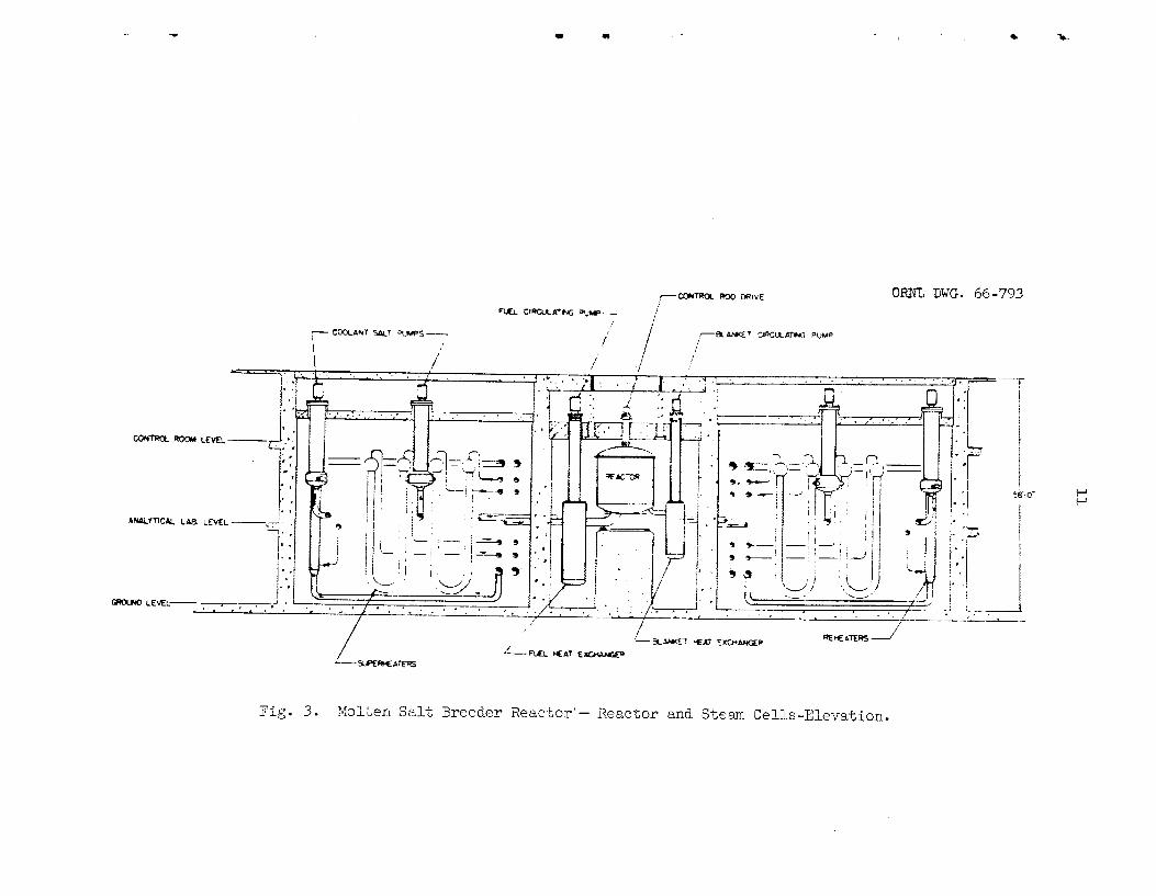
Figure 3 shows an elevation vlew of -the reactor and Sndlcates the position of equipment i n the various ce l l s . the react.0~ ce l l , shows the location of the reactor, pumps, and fuel and blanket heat exchangers. The RasteBloy M reactor vessel bas a side wall thickness of about l - l / k - in. and a head thickness of about 2-214 in.; it i s designed t o operate a t 1200°F 2nd 150 psi. The plenum chambers, with l/k-fn.-thick walls, comunlcate w i t h the external heat exchangers by concentric in le t -out le t piping. Bypass flow through these s l i p Joints i s about; 1s o f the t o t a l flow. As inaicatea In Fig. 5 ) the heat exclhangeps are suspended Prom t he top of -the cell and are located below the reactor, Each f u e l prarnp has a f r e e f lu ia surface and a storage volwe &-E& pellnit rapid drainage of f u e l f l u id f-mmthe core upon loss of flow. I n addition, the fuel salt can be drained t o the dump tanks when the reactor 5s shut down f o r an extended t h e . The en t i r e reactor e e l l is kept at; high temperature, while cold "'PlngersF* and thermal insulation surround stmctaral support members and a l l special equipment which must be kept a% relatdvely l o w temperatures, Tne control rod drives a re located above the core, and the control rods are inserted in to the cent ra l region of the core.
Figure 4, a plan view of
Figure 5 i s an elevation of the reactor cell.
The inner pipe has s l i p joir;f-,s t o accommodate thermal expansion.
Tbe reactor vessel, about 14 f t i n diameter by about; 15 f t hi&, contains a 10-ft-dim core assembly eoqosed of reentry-type graphite fuel cel ls . The graphite tubes are attached t o %he two plenum chambers a t thti bottom of the reactor w-ith graphite-%c-m%al t rans i t ion sleeves, Fwl. from the entyance plenum flows up fuel passages i n %he outer region of the fue l cell and dorm thmugh a single cent ra l passage t o %he exit pkerim, then t*u the pump and back t o the yeactor. blanket plus a 1/4-ft-tbick gmphite re f lec tor smxroimd the core e
bJ.a&e.t sa l t a lso permeates the fnters.t%ces of the eo= l a t t i c e so
fuel. salt,
The f u e l Plows f r o m the exit plenum t+o the heat exchangers, A i-l/2-JE"t;-tlmick molten-salt
The
feflufle ma.t,erial flows ta?ro.Eagh the core W'ith0U-b m i X % n g Vith the fissile
!!%.e lGBR requires structural i n t eg r i ty of %he graphite: f i e 1 ce l l . I n order t o relduee the e f fec t of radiation damage, the fuel eelis have Seen made smLP t o reduce the fast flux graclient across the graphite walle Also, the cells are anchored on ly a t one end t o permit axial move- ment. The eore wePwne has bee, made large in order t o reduce the flux le-sel i n the core, I n addi t ion , the rea.c%or 2,s designed t o p e a t re- pbeement of the entire graphite core by remote means if mquired.
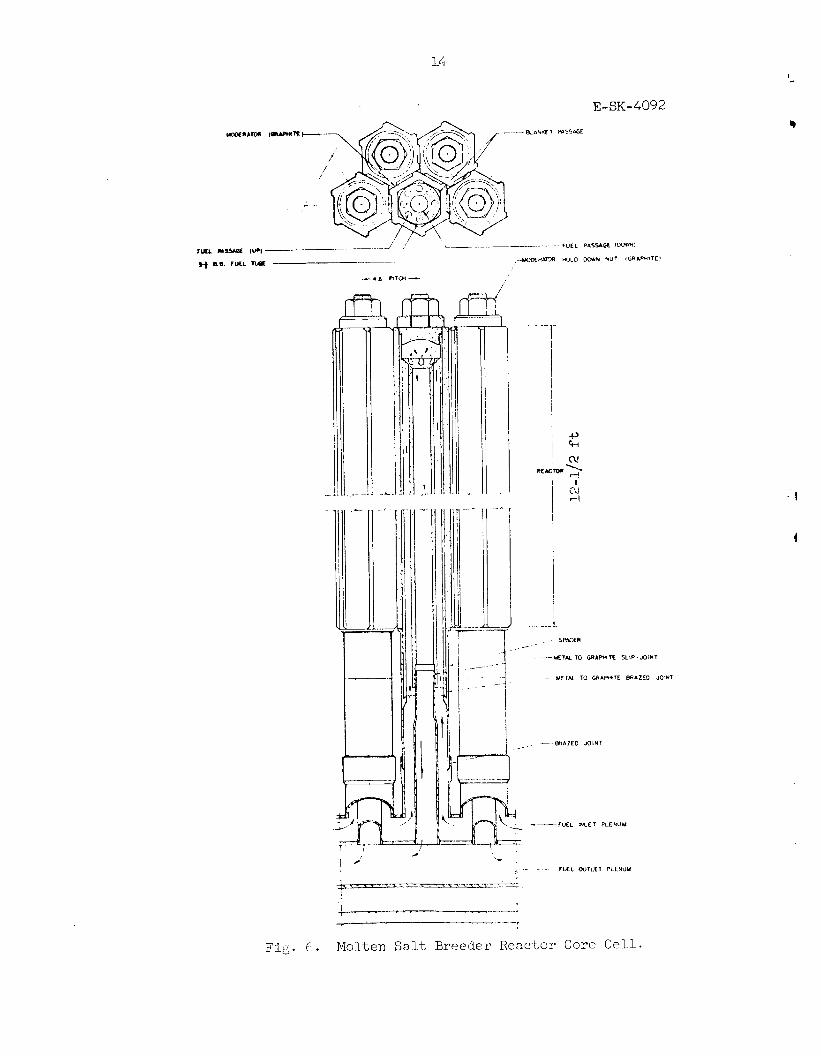
Figure 6 shows a cross section of' a fuel cell, Fuel f lu id flows upward through the small passages an& downward through the large eentm.l

10
I-
U
W
n
d
d
E s
I
11
-P r
i
0

1%
4

I
ORNL DWG. 66-794
~ O N S ~ A N T suppop1 MLkGERS
'i; I
..
..
t
. ..
i
Pig. 5. IvI~lten Sa1.t Breeder R e a c t u r - heac tor Cel.l-E~Levat,ion.
14
E-SK-4092
/
I
-1
i
mbcw ‘ d
” 1
1 cu 7-4
- - k E T N TO G R A W T C 5LIP.JOINl
- METAL TO GRARITE BRAZED JOINT
- - - M A Z E D JOlHT
. ‘- 1 . - - FUtL W T L E l PLEVUU
.- e_.> 1 . .7
1 ’
Fig . C . Molten Salt, Breeder Reactor Core Ce1.l.

passage. The outside diameter of a fue l c e l l tube i s 3.5 in . ; there aye 534 of these tubes spacea on a 4.8-in0 t r iangular pitch. assemblies are surrounded by hexagonal blocks of moderator graphite with blanket s a l t f i l l i n g the in t e r s t i ce s , i s 75% graphite, 1% f u e l s a l t , and fl blanket s a l t by volume.
The tube
The nominal core composition
A summary of parameter values chosen f o r the MSBR design i s given i n Table 1.
Fuel Processing
The primary objectives of fuel processing a re to purify and recycle f i s s i l e and ca r r i e r components, and minlmize fPssile inventory while holding losses t o a low value, The f luoride volatility-vacuum d i s t i l l a - t ion process f u l f i l l s these objectives through simple operations.
The core fue l i s conveniently processed by fluoride v o l a t i l i t y and vacuum d i s t i l l a t i o n . Blanket processing i s accomplished by fluoride v o l a t i l i t y alone, and the processfng cycle twe. is short enough t o main- t a i n a very l o w concentration of f iss i le material. absorbed by f u e l s a l t and reduced t o reconsti tute a fue l - sa l t mixture of the desired composition.
The eff luent uF"6 is by treatment with hydrogen t o
Molten-salt reactors are inherently suited t o the design sf p ~ o - cessing f a c i l i t i e s in tegra l with the reactor plant; these f a c i l i t i e s yequire only a small amount of c e l l space adjacent t o the reactor ce l l . %cause a l l services and equipment available t o the reactor am available t o the processing plant and shipping and storage charges a re eliminated, in tegra l processing f a c i l i t i e s permit s ignif icant savings i n capi ta l and operating costs. Also, the processing plant inventory of f issi le material is greatly reduced, resul t ing i n l o w fuel inventory charges and improved f u e l u t i l i za t ion character is t ics f o r the reactor.
The pr incipal steps i n corn and blanket stream processing of the MEBR are shown i n Fig. 7. A slnall side stream of each f l u i d is eontinu- ously withdrawn from the f u e l and blanket c i rculat ing loops and cireulatec2 thmugh the processing system, A f ' t e r processing, the decontaminated. fluids are returned t o the reactor a t some convenient point-for examyle, vEa the f u e l and f e r t i l e stream storage tanks;.
Fuel inventorles retained i n the processing plant are estimated t o be about IC$ of the reactor system inventory f o r core processing, ana less than 1% f o r blanket processing.
Heat Exchange and Steam Systems
The s t ruc tura l material fo r all components contacted by molten s h l t i n the fuel, blanket, and coolant systems, including the reactor vessel, pumps, heat exchangers, piping and storage tanks, is Hastelloy N.
The primary heat exchangers are of the tube-and-shell type. Each she l l contains two concentric tube bundles connected i n se r i e s and

Table 1. Parameter Values of MSBR Bsl@I
Power, Mv Thrml E l e c t r i c a l
meml e f f i c l ency
Plant f a c t o r
Dluensiona, f t Core height C o r e dlnmetcr Blanket thickness
Rndial Irr.inl
Reflector thickneas
volumes, f t 3 Core Blanket
V o l ~ m f ract iona core
Fuel s a l t F e r t i l e s o l t Modem t o r
F r r t i l e s a l t Blanket
S a l t volumrs, f t 3 Fuel
C O R
Blanket Plena Rcot exchanger end piping Processing
To ta l
F e r t i l e core Blanket Hrat exchawer and piping Stomge (Pa decay) Pmcesaing
To ta l
%It compositions, mole $ Fuel
LiF BrF2 U F ~ ( f i s s i l e )
F e r t i l e L W BeF2 Wlt I J F ~ ( f i s s i l e )
Core atom r s t l o s Th/U c/u
F i s s i l e inventory, k3
F e r t i l e inventory, loo0 b3
Pmcesslng
Cycle t i m e , days
Fate, f t3/day
V o l a t i l i t y process
V o l a t i l i t y process
Unit processing cost , $/rt3
2220 1000
0.45
0.80
12.5 10.0
1.5 2.0 0.25
982 1120
0.169 0.0735 0.7575
1 .o
166 26 1147 3'1 5 33
717
72 1121 100
2066 24
3383
63.6 36.2 0.22
71.0 2.0
27.0 O.ooo5
41.7 5m
'69
260
Fuel F e r t i l e Stream Streom
47 23

? m 8'
S O R B E R S toto I?.AP
1M430.C
MAKE-UP w6 I VOLATILE F P : ,'-E 1
I I son B E R S
COLD TRAP I
VF6 +
VOUllLf F P
J WAKE-UP
G, Fe N.
L F L', '-?, StCYCLf
- H2 P E D K e O METALS
Fig. 7 . Fuel and Fertile Stream Processing for the MSBR.

18
attached t o fixed tube sheets. section of tubes, enters a plenum a t the bottom of t h e exchanger, and then flows upward t o the pump through the center section of tubes. ing a t the top, the coolant s a l t flows on the baffled shell-side of the exchanger down the central core, under the b a r r i e r t h a t separates the two sections, and up the outer annular section.
The f u e l s a l t flows downward i n , t h e outer
Enter-
Since a large temperature difference e x l s t s i n t h e two tube sections,
The design permits d i f f e ren t i a l tube growth between the two sec- To accomplish t h i s ,
the tube sheets a t the bottom of the exchanger a re not attached t o the she l l , t ions without creating troublesome s t r e s s problems. the tube sheets are connected a t the bottom of the exchanger by a bellows- type joint . Th i s arrangement, essent ia l ly a f loa t ing plenum, permits enough re la t ive motion between the cent ra l and outer tube sheets t o com- pensate f o r difference i n Lube growth without creating intolerable s t resses i n e i the r the joint , the tubes, o r i n the pump.
The blanket heat exchangers increase the temperature of the coolant leaving the primary core heat exchangers, Since the coolant-salt tempera- t u re r i s e through the blanket exchangers i s small and the flow ra te i s re la t ive ly high, the exchangers a re designed f o r a s ingle shell-side pass f o r the coolant s a l t , although two-pass flow i s retained f o r the blanket s a l t i n t he tubes. Straight tubes with two tube sheets a re used.
The superheater i s a U-tube, U-shell exchanger using d isc and dough- It is a long, slender exchanger having nut baf f les with varying spacing,
re la t ive ly large baf f le spacing. shell-side pressure drop and by the temperature gradient across the tube wall, and i s greatest i n tihe central portion of the exchanger where the temperature difference between the f l u i d s i s high. The supercr i t ica l f l u i d enters the tube side of the superheater a t 700°F and 3800 ps i and leaves a t 1OOOOF and 3600 p s i I
The ba f f l e spacing is established by the
The reheaters t ransfer energy f romthe coolant salt t o the working f l u i d before i t s use I n the intermediate pressure turbine, A shell-tube exchanger i s used, producing steam a t 1000°F and 54.0 p s i o
S b c e the freezing tempeagatuTe of the secondary s a l t coolant i s about 700°P, a high working f l u i d i n l e t temperature i s required. along with prime f luid, a re used i n ra is ing the temperature of the working f l u i d entering the superheaters, exchanger and leaves a t a pressul-e of 3550 p s i and about 8 7 0 " ~ . then injected in to the feedwater i n a mixing tee , producing f l u i d a t 700°F and 3500 psi . a pressurizer (feedwater pump) before the f l u i d enters t he superheater.
Preheaters,
Pr-fme f l u i d goes through a preheater It i s
The pressure i s then increased t o about 3800 psi by

13
CAPITAL COST ESTmTES
Reactor Power Plant
Preliminary estimates of the capi ta l cos t of a lOOO-W(e) molten- s a l t breeder reactor power s ta t ion indicate a d i r ec t construction cost of about $80,4 millionn After supplying the indirect cost fac tors used i n the advanced converter evaluation,' an estimates t o t a l plant cost of $113.6 million is obtained. A summary of plant costs is given i n Table 2. The conceptual design w a s not sufficiently detailed t o permit a com- ple te ly re l iab le estimate; h o ~ m e r , the design and estimates were studied thoroughly enough t o make meaningful comparisons w i t h previous converter reactor plant cost studies. The re la t ive ly Pow cap i t a l cost estimate obtained resu l t s from the small physical s ize of the MSBR and the simple control requirements. t ha t the cost of an MSBR power s ta t ion wfl .1 be as l o w as for stat ions u t i l i z ing other reactor concepts.
The resu l t s of the study encourage the bel ie f
The operating and maintenance costs of the MSBR were not estimated, Based on the ground rules used i n reference 1, these costs would be about 0 e 3 miU/kwhr( e 1 Fuel Recycle Plant
The capi ta l costs associated with fuel recycle equipment were obtained by itemizing and costing the mjor p'mcess equfpment required, and est#%- mating the costs of s i t e , bxil.dingsj instlglmentation, waste disposal, and building services associated with fuel recycle.
Table 3 summarizes the d i r ec t construction costs, the indirect costs, and t o t a l costs associated with the integrated processing faci l i ty having approximately the required capacity,
The operatlng and maintenance costs for %he f u e l recycle f a c i l i t y include labor, labor overhead, chemicals, u t i l i t i e s , and maintenance materials, The t o t a l annual cost f o r the capacity considered here (15 ft3 of f u e l s a l t per day and 105' ft3 of fe r t i l e salt per day) i s es t i - mated t o be $721,230, wh9eh i s equivalent t o about 0.1 mill/kwhy(e) n 2
A breakdown of these charges i s given i n Ta%le 4.
The f u e l cycle cost and the fue l yield are closely related, yet independent i n the sense that two nueleay designs can have s imilar costs but s ignif icant ly different yielas, The o%Jective of the nuclear design calculations was primarily t o find tbe conditions t h a t gave the lowest f u e l cycle cost, and. then, without appreciably increasing %his cost, t he highest fuel yield,

a Table 2. Preliminary Cost-Estimate Summary
1000-Mw(e) Molten-Salt Breeder Reactor Power Station
I_
Federal Power Commission Account Costs ($1000)
b 20 Land and Land Rights
21 Structures and Improvements 211 Ground Improvements 212 Buildings and Structures
.l Reactor buildingc
.2 Turbine building, auxi l iary building,
.3 Offices, shops, and laboratories
.4 Waste disposal building
.5 Stack
.6 Warehouse e 7 Miscellaneous
and feedwater heater space
Subtotal Account 212 Total Account 21
22 Reactor Plant Equipment 221
222
223
224
225
226 227 228 229
Reactor Equipment .1 Reactor vessel .2 Control rods .3 Shielding and containment .4 Heating-cooling systems and vapor-
suppression system .5 Moderator and. ref lector .6 Reactor plant crane
Heat Transfer Systems .l Reactor coolant system .2 Intermediate cooling system .3 Steam generator and reheaters .4 Coolant supply and treatmentd .5 Coolant s a l t inventory
Nucleay Fuel Hand.ling and Storage
Nuclear €%el Processing and Fabrication
Radioactive Waste Treatment and Disposal
I n s t m e n t a t i o n and Controls Feed-mter Supply and Treatment Steam, Condensate, and 3Fw Piping Other Reactor Plant; Equipmen% (Remote
Subtotal Account 221
Subtotal Account 222
(Drain Tanks )
(included i n l?~.~el Cycle Costs)
(Off-Gas System)
Maintenance) Total Account 22
360
866
4,181 2,832
1,160 150 76 40
T ' G . 2 8 9,335
1,610 250
1,477 1,200
1,089 265
T W
6,732 1,947 9,853
300 354
19,186
1,700
45 0
4,500 4,051 4,069 5 9 oooe
44,847
3
Continued *See Table 3 f o r these costs, which are not included here.

'2 i
Table 2 (continued)
Federal Power Commission Account costs ($lOOo)
23
24
25
Turbine -Generator Units 231 Turbine-Generator Units 232 Circulating Water System 233 Condensers and Auxiliaries 234 Central Lube O i l System 235 Turbine Plant I n s t m e n t a t i o n 236 Turbine Plant Piping 237 Auxiliary Equipment f o r Generator 238 Other Turbine Plant Equipment
Total Account 23
Accessory Electr ical 241 242 Switchboards 243 Station Service Transformers 244 Auxiliary Generator 245 Distributed Items
Switchgear, Main and Station Service
Total Account 24
Miscellaneous
Total Direct Construction Costg Total Indirect Cost Total Plant Cost
Estimates are based on 1966 costs, assuming an established molten- a
salt nuclear power plant industry.
bLand costs are not included i n t o t a l d i r ec t construction costs.
NSBR containment cost i s included i n Account 221.3. C
'Assumed as $300,000 on the basis of MSRE experience.
%he anrple MSBR allowance f o r remote maintenance may be too high, and some of the included replacement equipment, allowances could more logically be classi f ied a s operating expenses ra ther than first capi ta l costs.
fBased on Bull Run plant cost of $160,000 plus -37$ fo r uncertainties,
%oes not include Account 20, Land Costs, !This i s jncluded i n the indirect costs

22
Table 3. S m r y of Processing-Plant Costs f o r 1000-Mw(e) M33
Instal led process equipment Structures and improvements Waste storage Process piping Process instrumentation Elec t r ica l auxi l ia r ies Sampling connections Service and u t i l i t y piping Insulation Radiation monit;o;.ing
Total d i r ec t cost
Construction overhead
Total constmction cost ( 3 6 of d i rec t costs)
Engineering and inspection (25% of t o t a l construction cost)
Subtotal- plant cost
Contingency (2576 of subtotal plant cost )
Total plant cost
$ 853,760 556,770 387,970 155,800 272,100 84,300 20,000
128,060 50,510
100,000
$2,609,270 782.780
$3,392,050
848, oxo
$4,240,060
I, 060,020
Table 4. summary of Operating and Maintenance Charges f o r Fuel Recycle i n a lOOO-Mw(e) MSBR
($/yead
Direct labor Labor overhead CBemf c a Is Waste containers U t i lit i e s Maintenance materials
Si t e Services and u t i l i t i e s Process equipment
Total. an?ual charges
$ 222!,000 179,600 14,640 28,270 80,300
2,500 35 , 880
160 , 040
$ 721,230 -

23
Analysis Procedures
Calculation Method. The calculations were performed with OPTIMERC, a combination of an optimization - code w i t h t he MERC multigroup, diffusion, equilibrium reactor code. equilibrium concentrations of the various nuclides, including f i s s ion products, and the f u e l cycle cost f o r a given s e t of' conditions. MF;RC permits up t o twenty reactor parameters t o be varied, within l i m i t s , i n order t o determine an optimum, by the method of steepest ascent. The designs were optimized essent ia l ly f o r m i n i m f u e l cycle cost, with l e s se r weight given to maximizing the annual *el yield. Typical param- e t e r s varied were the reactor dimensions, blanket thickness, f rac t ions of fuel and f e r t i l e s a l t s i n the core, and f u e l and fe r t i l e stream pro- cessing rates.
MERC3 calculates the nuclear performance, the
O F T I -
Several equations were included i n the code f o r approximating cer- t a i n cap i t a l and operating costs t ha t vary with the design parameters ( for example, cap i ta l cost of the reactor vessel, which var ies with the reactor dimensions). These costs were automatically added t o the f u e l cycle cost i n the optimization routine so t h a t the optimization search would take into account a l l known economic factors . However, only the f u e l cycle cost i t s e l f i s reported i n the r e su l t s .
Modified GAM-1 -THERMOS cross-section l i b r a r i e s were used t o com- pute the broad group cross sectlons f o r these calculations. It was assumed t h a t a l l nuclides i n the reactor system are a t t h e i r equilibrium concentrations. To check th i s assumption, a typical reactor design was examined t o determine the operating t i m e required f o r the various uranium isotopes t o approach t h e i r equilibrium concentrations from 8 s ta r tup with 23?J. It was found that rium concentrations i n less than two years. Uranium-234 was within 95$ of equilibrium a f t e r eight years, while was within 8C$ a f t e r 10 years. 23% t o 23% i n the fuel, the equril'brlum calculation appears t o be a good representation of the l i fe t ime performance of these reactors, even f o r s ta r tup on "%,
and 23?J were within 95% of their equilib-
Since the breeding pe r fomnce depends mainly on the r a t i o of
Basic Assumptions
Economic. The basic economic assump-tions employed i n the calcula- t ions a re given In Table 5. taken from the current AEC price schedule.
The values of the f t s s f l e isotopes were
The processing costs are based on these given i n the section en t i t l ed "Capital Cost Estimates'' and are included i n the fuel cycle costs. cap i t a l and operating costs were estrimated separately f o r each stream as a function of plant throughput, based on the volume of s a l t processed. The t o t a l processing cost i s assumed t o be a function of the throughput t o some f rac t iona l power called the scale factor,
The

24
Table 5. Basic Economic Assumptions
~~
Reactor power, Mw(e)
mermal efficiency, $ Load fac tor
Cost assumptions
Value of 233v ana 233~a, $/g Value of 235, $ / g Value of thorium, $/kg Value of ca r r i e r s a l t , $/kg
Capital charge, annual ra te , $ Plant Nondepreciating capi ta l , including
f i s s i l e inventory
Processing cost, $/fts s a l t
f i e 1 ( a t 10 &'/day processing pate) Blanket ( a t 100 ft3/day processing rate)
Processing cost scale fac tor (exponent )
1000
45 0.80
14 12 12 26
12
10
228 8.47
0.4
Processing. The processing scheme i s tha t indicated i n Fig. 7'. A f iss i le material l o s s of O,l$ per pass through processing was assumed.
I n addition t o the basic processing scheme employed, r e su l t s were a l so obtained f o r t h e case t h a t Pa can be removed d i r ec t ly from the blanket stream, The improvement i n performance under these circumstances i s a neasure of the incentive t o develop Pa removal ab i l i t y .
Fission Product Behavior. The disposit ion of the various f i s s ion products was assumed a s shown i n Table 6. other fission gases has a s ignif icant influence on nuclear performance, A gas-stripping system i s provided t o remove these gases from the fue l s a l t , However9 par t of the xenon could diffuse in to the moderator graphite. of 0.005 was assumed,
The behavior of 135Xe and
I n the calculations reported here, a I3'Xe poison f rac t ion
Corrosion Product Behavior. The control of corrosion products i n molten-salt fue ls does not; appeal. t o be a s ignif icant problem, and the e f fec t of corrosion products was neglected i n the nuclear calculations. The processing method considered here can control corrosion pmduct buildup i n the fuel .

25
b
b
Table 6. Disposition of Fission Products i n MSBR Reactor and Processing Systems
~-
Elements present as gases; assumed t o be par t ly absorbed by raphite and par t ly removed by gas s t r ipping (1 8 poisoning assumed): Kr, xe
Elements t h a t p la te out on metal surfaces; assumed t o be remved instantaneously: Ru, Rh, Pd, Ag, I n
Elements t h a t form vo la t i l e fluorfdes; assumed t o Se, Br, Nb, Mo, Tc, be removed i n the fluoride v o l a t i l i t y process: Te, I
Elements t h a t form stable fluorides l e s s vo la t i l e Sr, Y, Ba, La, Ce , than LiF; ass-med t o be separated by vacuum Pr, Nd, Pm, Sm, Eu, d i s t i l l a t i o n : a, !I5
Elements t h a t a r e not separated from the c a r r i e r sa l t ; assumed t o be -.emoved only by salt discard: Rb, Cd, Sn, C s , Zr
Nuclear Design Analvsis
The important parameters describing the MSBR design a re given i n Table 1, f o r the evaluation or by the engineering design. These include the therm- a l efficiency, plant factor, cap i t a l charge rate , maximum fuel velocity, s ize of f u e l tubes, processing costs and f iss i le loss ra te , and the out- of-core f u e l inventory. The parameters which were optimized by OPTIMERC were the reactor dimensions, power density, the core composition includ- ing the C/U and Th/U ra t ios , and the processing rates.
Many of the parameters were bas ica l ly fixed by the ground rules
Nuclear Performance. The r e su l t s of the calculations f o r the MSBR design a re given i n Table 7, and the neutron balance i n Table 8. basic design has the inherent, ad-ran%age of EO neutron losses to struc- t u r a l materials other than the moderator. Except f o r some unavoidable loss of delayed neutrons i n the external f u e l eircuit, there is almost zero neutron leakage from the reactor because of the th ick blanket, The neutron losses t o fission products are mrinia5zed by the ava i l ab i l i t y of rapid and inexpensive integrated processfng.
The
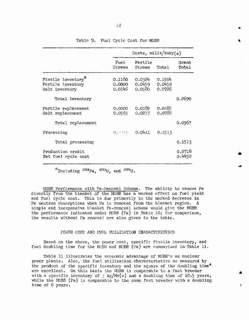
Fuel Cycle Cost. The components of t he f u e l cycle cost f o r the MSBfi a re given i n Table 9' The main components a re the f iss i le inventory and processing costs. The inventory costs a r e ra ther r ig id f o r a given reac- t o r design, since they a re largely detel-anined by the assumed external f u e l volume. The processing costs are, of course, a function of the pro- cessing cycle times, one of the chief parameters optimized i n t h i s study,

26
Table 7. MSBR Performance
4
L
Fuel yield, !$ per annum
Breeding r a t i o
F i s s i l e losses i n processing, atoms/fissile absorption
Neutron production per f iss i le absorption (7 E)
Specific inventory, kg fissile/Mw( e)
Specific power, Mw(t)/k.g f iss i le
Power density, core average, kw/ li t e r
Gross
I n f u e l s a l t
Neutron flux, core average -i ioL4 neutrons sec
Thermal
Fast
Fast over 100 kev
Thermal flux factors, core, peak/mean
Radial
Axial
Fraction of f i ss ions i n f u e l stream
Fraction of f i ss ions i n thermal neutron group
Mean 7 of a3U
4.86
1.0491
0.0057
2.221
0 * 769
2.89
80
473
6.7 12.1
3 . 1
2.22
1.37
0 987
0.806
2.221
1.958 Mean 7 of 23%J

27
JL
‘ f
Table 8. MSBR Neutron Balance
Neutrons per F i s s i l e Absorption
V5a t e r i a l Produced Absorbed Ab sorbed Total by Fission
Z7Np
=8v Carrier sa l t
(except %i)
6Li Graphite
13’xe
149%
l5lsm
Other f i s s ion products
Delayed neutrons
b
los ta
Leakage
Total
0.9710 0.0025 0-0059
0.0079
0.9119 0.8090 2,0233
0.0936 0.0004 0.0010
0 + 0881 0.0708 0,1721
0.0115 0.0001 o.oO01
0.0014
0.0009
0.0623 0.0185
0,0030
0.0300
0.0050
0.0069
0.0018
o 0196
0 0050
0,0012
2.2209 0.8828 2.2209
%clayed neutrons emitted outside the core.
bLeakage, including neutrons absorbed in the re f lec tor .
28
Table 9. Fuel. Cycle Cost f o r MSBR - - --
Costs, mills/kwhr( e )
Fuel Fe r t i l e Grand Stream Stream Total Total
_I
0.1180 a F i s s i l e inventory F e r t i l e inventory 0.0000 Sal t inventory 0.0146
Total inventory
F e r t i l e replacement 0.0000 Salt rep1.acemen-L 0.0$5$
Total replacement
Processing * ~ ! I’
Total. processing
Production c red i t Net fue l cycle cost
0,0324 0.0459 0.0~80
0.0185 0.021.7
0.0411
0.1504 0.0459 0 0726
0.2690
0.0185 0.0782
0.0967
0.15 1.3
0 15 1.3
0.0718 0,4452
a Including 233~a, 2 3 3 ~ ? and z35.
MSBR Pcrfcrmance with Pa-Senoval Scheme. The a b i l i t y t o remove Pa d i rec t ly from the blanket of the MSBR has a marked ef fec t on f u e l yield and fuel cycle cost. Pa neutron absorptions when Pa i:; removed from the blanket region. simple and inexpenslve bianket Pa-removal scheme r;ould give the MSBR the performance indicated under M B R (Fa) i n Table 30; f o r comparison, the resu l t s wjthout Pa resncval are also given i n the table .
This i s due primarily t o the markeii decrease i n A
Based on the above, the pover c o s t , specific: f i s s i l e inventory, and fuel doubling time f o r t h e lC33Y; and MSBR (Fa) are swaar i zed i n Table 11,
Table 12. i l l u s t r a t e s the economic advantage of MSBR‘s as nuclear power plants. Also, the fuei u t i l i za t ion character is t ics as measured by the product of the specific inventory and the square of t h e doubling t ime4 a re excellent. On t l ? k basis the II’LSBR i s comparable t o a fast breeder w i t h a spec i f lc inventory of 3 lig/M.w(e) and a doubling tifie of 10,5 years, while the XSBR (Pa) 2s comparable to the same f a s t breeder with a doubling time of 6 years.
P
4

29
1
c
Table 10, Comparison of I@BR Performance With and Without Pa Removal
~
MSBR MSBR (Pa) (~5, t~lout ; Pa (With Pa
Process) Removal )
Fuel yield, $ per annum
Breeding ra t io
Fuel cycle cost, mills/kwhr
Specific Inventory, kg/m(e)
Specifdc power, M(t)/kg
Neutron production per fissile absorption ( 7 ~ )
Volume fractions, core
Fuel
Fertile Mode r a t o r
Salt volumes, ft3
Fuel Core
External
Total
Ferti le
Total
Core atom r a t io s
4086
1.0491
0
0 0 769
2.89
7.95
1.0713
0033
o e 682
3.26
2,221
3383
2 227
166 551
"97


3 1.
In t e rna l DSstribution
1. 2, 3. 4. 5. 6. 7. 80 9. LO 0
11 0
3.2, 13 14 15 16 17 18 e 19 20.
21-41, 42 43 0
44. 45 0
46 e 47 0
G. M, Adamson C. 9, Barton H. F. D a w n S. E. Beall C. E, Be t t i s E. So Bet t i s F, F, Blankenship R. J e Braatz R. Be BrSggs S. Cantor R, S o Clarlsmith W, L, Carter W, H. Cook G. A. Cristy F. Lo Culler D. E. Perguson A, P, Fraas W e R e Grimes A, G, GrindEell P. N. Haubenreich Po R, Kasten @. R e Kennedy S o S. Kirslis J. A. Lane M e I, Lundin R, N. Lyon He G o MacPherson
R. E, ESacPherson H. C. McCul .ay W. B. McDonald H, F. McDuffie A. J. Miller R . L. Moore €4, Lo Myers R e C, Olson A. M. Perry T. W. Pickel R. C, Robertson A, W. Savolainen D e Scott J, H. Shaffer M. J, Skinner
R. E. Thoma G. M. Tolson D. 3. Trauger A, M e Weinberg
I. Spiewak
J. Eo Westsik J e C, White G. D. Whitman Central Research Library Y - I 2 Document Reference Section Laboratory Records Laboratory Records, RC
79 e
80. 81 , 82 e 83 8 4 0
65-99, 100
101-102 .
External Distribution
D. I?. Cope, AEC, OR0 C, B. Deering, AEC, OR0 Re G. Garrison, AEC, Washington R. E, Hoskins, TVA, Chattanooga W. J. Larkin, A X , OR0 S. R. Sapirie, AEe, OR0 Division of Technical Information Ektension (DTIE) Research and Development Division, OB0 Reactor Division, OR0
1,
'f