summary - itu · director of br will include the results in his report to ... - modifying antenna...
TRANSCRIPT

Summary:Summary:
1) How to Identify Satellite Networks and other
Systems for which Coordination is Required ?
2) Several Interference Criteria utilized to evaluate
compatibility between GSO satellite networks.
Trigger Arc
DT/T
C/I
3) New Coordination Criteria under Study
4) Possible methods to be used to facilitate
coordination and sharing scenario between GSO.
5) How to optimize a filing to be submitted to ITU ?
2
3
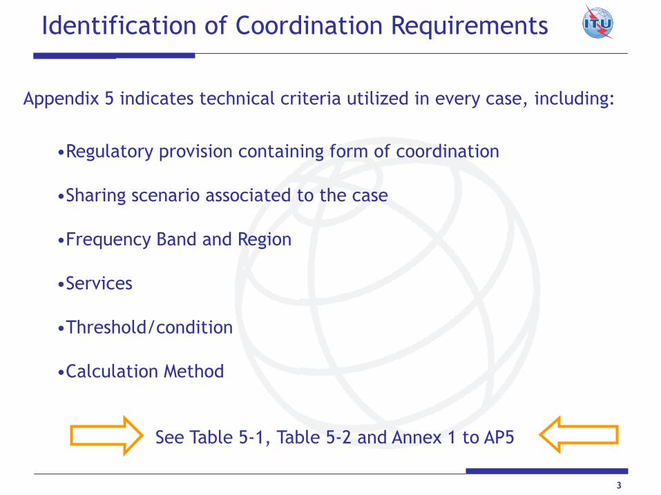
Identification of Coordination Requirements
Appendix 5 indicates technical criteria utilized in every case, including:
•Regulatory provision containing form of coordination
•Sharing scenario associated to the case
•Frequency Band and Region
•Services
•Threshold/condition
•Calculation Method
See Table 5-1, Table 5-2 and Annex 1 to AP5

4
Criterion of Coordination Arc:
To identify satellites with frequency overlap operating in the
same direction inside the window of ± 7 , ± 8 , ± 12 or ± 16
degrees from nominal orbital longitud, depending on the
frequency band, service and Region.
Applicable to satellite networks in FSS (non plan)
BSS (non plan)
Meteorological-Satellite
associated Space Operations
in specific frequency bands ( see AP5 )
Utilized by BR to identify coordination requirements.
Coordination between GSO/GSO under provision 9.7

5
Coordination between GSO/GSO under provision 9.7
Coordination Arc is applied
Simple but Useful Exercise:
Approach Identifying Satellite Networks with which coordination may be required by using:
SNS-Online or SpaceQuery: SNS Online Link http://www.itu.int/sns/query_builder.html
Frequency
Band
GSO Window=
20 E ± 8 degrees

6
Coordination between GSO/GSO under provision 9.7Coordination between GSO/GSO under provision 9.7
Result of Exercise of Coordination Arc ApproachResult of Exercise of Coordination Arc Approach

Coordination between GSO/GSO under provision 9.7
Criterion of T/T > 6 %
Mask used by BR to establish coordination requirements in
any other scenario where CA is not applicable.
Utilized by Administrations to request BR to include or
exclude networks in coordination process under No.9.41
Described by Appendix 8 to RR.
It measures the increase of Noise Temperature at Rx due
to Interference as a generic method.
It does not take into account: - wanted signal.
- interfering spectrum shape
T/T > 6 % => Potential Harmful Interference
Further detailed analysis is needed to ensure that
coordination is really needed ( e.g. C/I )
T/T 6 % => No Harmful Interference
7

T/T : Introduction to General MethodT/T : Introduction to General Method
8
Wanted sat. networkWanted sat. network
p’p’ ggtt’’
ggrr T (K)T (K)
T (K)T (K)
Interfering sat. networkInterfering sat. network
T / T = T / T = ((p’ p’ ggtt’ ’ ggrr ) ) / / KLTKLT
AP8 describes the method AP8 describes the method
including definitionsincluding definitions
p p rsrs
p rep re
TsTs
TTee
TxTx
ESES RxRx
ESES
Transmission gainTransmission gain ::
Valid for Simple Freq. Changing Transponders (Bent Pipe ) onlyValid for Simple Freq. Changing Transponders (Bent Pipe ) only.. Not applicable when satellite has onNot applicable when satellite has on--board signal processing board signal processing
(digital regenerating transponders, change of modulation, etc). (digital regenerating transponders, change of modulation, etc).
This case requires separate treatment of up and downlinks.This case requires separate treatment of up and downlinks.
= = ppre re / / pprsrs Power received at the earth Power received at the earth stn.stn.
Power received at the satellitePower received at the satellite
Equivalent Satellite Link Noise Temperature:Equivalent Satellite Link Noise Temperature:
T= Te + T= Te + Ts (K)Ts (K)
Interfering power density levelInterfering power density level
S’(Interfering)S’(Interfering)
99
S (Wanted)S (Wanted)
ww
GG44((ww))
p’p’ss
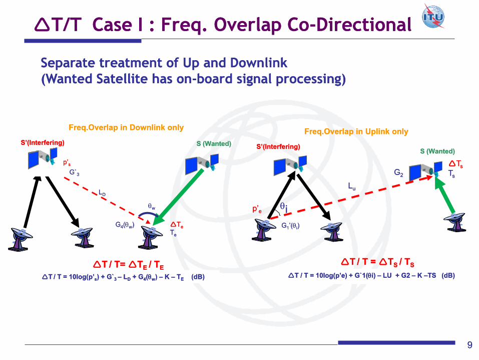
TT / / T = 10log(T = 10log(p’p’ss) + G`) + G`3 3 –– LLDD + G+ G44((ww) ) –– K K –– TTEE (dB)(dB)
G`G`33
TTee
TTee
LLDD
TT / / T= T= TTE E / / TTEE
Freq.OverlapFreq.Overlap in Downlink onlyin Downlink only
T/T Case I : Freq. Overlap CoT/T Case I : Freq. Overlap Co--DirectionalDirectional
Separate treatment of Up and DownlinkSeparate treatment of Up and Downlink
(Wanted Satellite has on(Wanted Satellite has on--board signal processing)board signal processing)
ii
GG11’(’(ii))
GG22
TTss
TTss
S’(Interfering)S’(Interfering) S (Wanted)S (Wanted)
p’p’ee
LLuu
T T / / T = 10log(T = 10log(p’ep’e) + G`1() + G`1(ii) ) –– LU + G2 LU + G2 –– K K ––TS (dB)TS (dB)
TT / / T = T = TTS S / / TTSS
Freq.OverlapFreq.Overlap in Uplink onlyin Uplink only
S (Wanted)S (Wanted) S’(Interfering)S’(Interfering)
1010
..
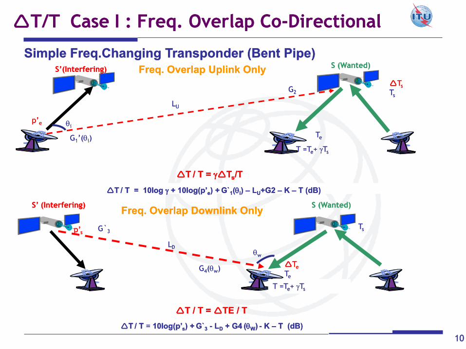
Simple Simple Freq.ChangingFreq.Changing Transponder (Bent Pipe)Transponder (Bent Pipe)
Freq. Overlap Uplink OnlyFreq. Overlap Uplink Only
ii
GG11’(’(ii))
GG22
TTss
TTss
p’p’ee
LLUU
TTee
TT / / T = 10log T = 10log + 10log(+ 10log(p’p’ee) +) + G`G`11((ii) ) –– LLUU+G2 +G2 –– K K –– TT (dB)(dB)
T =TT =Tee+ + TTss
TT / / T = T = TTss//TT
T/T Case I : Freq. Overlap CoT/T Case I : Freq. Overlap Co--DirectionalDirectional
TTee
TTee
TTss
LLDD
GG44((ww))
p’p’ss G`G`33
ww
TT / / T T = = 10log(10log(p’p’ss) +) + G`G`33 -- LLDD + G4+ G4 ((WW)) -- K K –– TT (dB)(dB)
T =TT =Tee+ + TTss
T T / / T = T = TE TE / / TT
S (Wanted)S (Wanted) S’ (Interfering)S’ (Interfering) Freq. Overlap Downlink OnlyFreq. Overlap Downlink Only

S’(Interfering)S’(Interfering) S (Wanted)S (Wanted)
1111
Freq.OverlapFreq.Overlap in both linksin both links
TT//T= T= ( ( TTee + + TTs s ) ) / / T T
ii
ww
GG11’(’(ii))
p’p’ee
p’p’ss
GG44((ww))
GG22
TTss
TTss
TTee
TTee
LLUU
LLDD
G`G`33
T =TT =Tee+ + TTss
T/T Case I : Freq. Overlap CoT/T Case I : Freq. Overlap Co--DirectionalDirectional
Simple Simple Freq.ChangingFreq.Changing Transponder (Bent Pipe)Transponder (Bent Pipe)
T / TT / T = ( = ( p’p’ss g`g`3 3 gg4 4 ((WW) ) ) / (k ) / (k llDD T) + T) + ((p’p’ee g`g`11((ii)) gg22 ) / (k ) / (k llUU T)T)
S’(Interfering)S’(Interfering)
1212
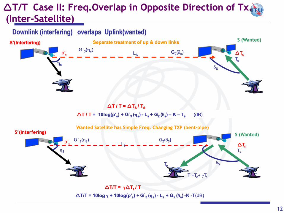
Downlink (interfering) overlaps Uplink(wanted)Downlink (interfering) overlaps Uplink(wanted)
S (Wanted)S (Wanted)
TT//TT = 10log = 10log + 10log(+ 10log(p’p’ss) +) + G`G`3 3 ((ss)) -- LLss + G+ G2 2 ((ss)) --K K --TT(dB)(dB)
SS
SS
p’p’ss LLSS
G`G`33((SS)) GG22((SS)) TTss
TTss
TTee
T =TT =Tee+ + TTss
TT//TT = = TTs s / / TT
T/T Case II: T/T Case II: Freq.OverlapFreq.Overlap in Opposite Direction of in Opposite Direction of TxTx..
(Inter(Inter--Satellite)Satellite)
p’p’ss
G`G`33((ss)) LLSS GG22((ss))
SS
ss
TTss
TTss
T T / / T T = = 10log(10log(p’p’ss) + G`) + G`3 3 ((ss)) -- LLs s + G+ G2 2 ((ss)) –– K K –– TTss (dB)(dB)
S’(Interfering)S’(Interfering) Separate treatment of up & down linksSeparate treatment of up & down links
T T / / T =T = TTS S / / TTSS
Wanted Satellite has Simple Freq. Changing TXP (bentWanted Satellite has Simple Freq. Changing TXP (bent--pipe)pipe)
S (Wanted)S (Wanted)

13
Coordination between GSO/GSO under provision 9.7
C/I Criterion
Utilized by BR to perform detailed examination of probability of
harmful interference when so requested by Administrations
under No.11.32A of RR.
Based on methodology and protection criteria defined by
REC ITU-R S.741-2 and associated Rule of Procedure
from RRB, or by common agreement between Adms.
It takes into account: - Wanted signal
(level and type of carrier-modulation)
- Interfering signal
(level and spectrum shape)
- Overlapped BandWidth
More accurate to perform inter-networks sharing analysis,
based on quality and availability objectives.
Used by operators in coordination meetings.

14
Concept of C/I:
C/I C/I = C/N + K= C/N + K Protection Protection ratioratio
( ( generally, between 12.2 generally, between 12.2 –– 14 dB, depending on the type of carriers )14 dB, depending on the type of carriers )
Result of your Link BudgetResult of your Link Budget
( ( considering objectives like S/N or BER, availability, etc )considering objectives like S/N or BER, availability, etc )
Protection required to ensure compatibility between networksProtection required to ensure compatibility between networks
**C/I examination will be presented in detail in a separate document**
15
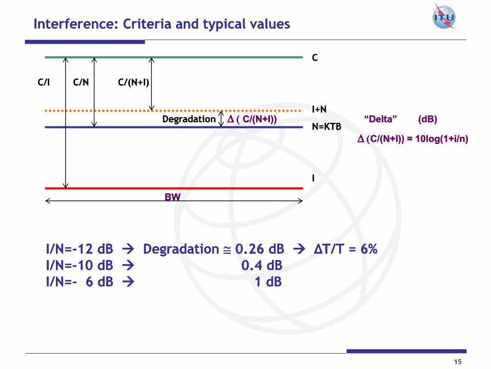
Interference: Criteria and typical valuesInterference: Criteria and typical values
C/I C/N C/(N+I) C/I C/N C/(N+I)
Degradation Degradation DD(( C/(N+I))C/(N+I)) “Delta” (dB)“Delta” (dB)
DD((C/(N+I)) = C/(N+I)) = 10log(1+i/n)10log(1+i/n)
CC
I+NI+N
N=KTB N=KTB
II
BWBW
I/N=I/N=--12 dB 12 dB DegradatioDegradation n @ 0.26 dB 0.26 dB ΔT/T = 6%ΔT/T = 6%
I/N=I/N=--10 dB 10 dB 0.4 0.4 dBdB
I/N=I/N=-- 6 dB 6 dB 1 dB1 dB
16
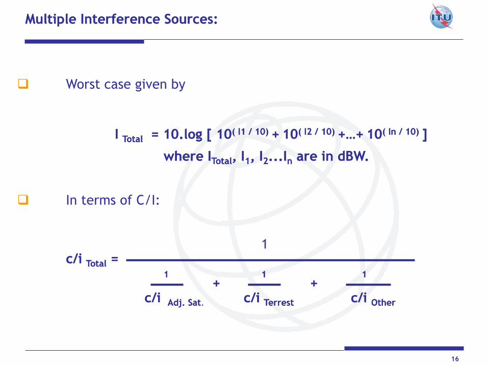
Worst case given by
I I Total Total = 10.log [ 10= 10.log [ 10( I1 / 10) ( I1 / 10) ++ 1010( I2 / 10) ( I2 / 10) +…++…+ 1010( In / 10) ( In / 10) ]]
wherewhere IITotalTotal, I, I11, I, I22...I...Inn are in are in dBWdBW.. In terms of C/I: 1 c/c/ii TotalTotal = = 11 11 11
+ ++ +
c/c/ii Adj.Adj. SatSat. c/c/ii TerrestTerrest c/c/ii OtherOther
Multiple Interference Sources:Multiple Interference Sources:
17
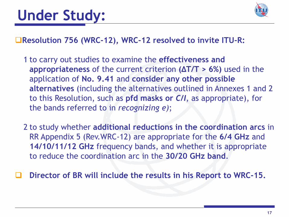
Resolution 756 (WRC-12), WRC-12 resolved to invite ITU-R:
1 to carry out studies to examine the effectiveness and
appropriateness of the current criterion (ΔT/T > 6%) used in the
application of No. 9.41 and consider any other possible
alternatives (including the alternatives outlined in Annexes 1 and 2
to this Resolution, such as pfd masks or C/I, as appropriate), for
the bands referred to in recognizing e);
2 to study whether additional reductions in the coordination arcs in
RR Appendix 5 (Rev.WRC-12) are appropriate for the 6/4 GHz and
14/10/11/12 GHz frequency bands, and whether it is appropriate
to reduce the coordination arc in the 30/20 GHz band.
Director of BR will include the results in his Report to WRC-15.
Under StudyUnder Study::

18
Ongoing studies are considering:
which frequency bands would be subject to the new coordination
criterion?
new threshold would be based on single-entry or multiple sources
of interference?
to apply different criteria for each combination of interfering and
interfered-with carrier type?
(noting that Recommendation ITU-R S.741 may not take into
account some modulation-coding schemes currently in use, as
well as the difficulties of identifying them using the current
RR Appendix 4 parameters)
the possibility of defining a reasonable range of technical
parameters (e.g. uplink G/T, downlink noise temperature,
antenna sizes)
identifying provisions and situations where the new criteria
should be applied

19
Contributions to studies are based on:
homogenous networks
separation of two and three degrees
possible levels of permissible interference and
associated loss of energy margin and capacity
See Annex 13 to the report of the
Working Party 4A Chairman

20
MMethodsethods to facilitate coordination andto facilitate coordination and
sharing scenario between GSOsharing scenario between GSO
Frequency Separation
- Band Segmentation
- Channeling Plan
Polarization
Improvement of antenna system spatial discrimination
-Design of Antenna gain contours, roll-off and service areas associated to
satellite beams
- Modifying antenna diameters in the ground segment
- Improvement to Earth Station Radiation Pattern
To Adjust orbital separation between adjacent satellites.
To Reorganize distribution of diferent types of carrier.
Use of advanced modulation/FEC technologies (eg. DVB-S2), signal coding and processing techniques (spread spectrum or CDMA, etc).
Re-engineering of the link budget, including modulation-FEC, power density levels, adjusting Quality and Availavibility Objectives in order to tolerate higher levels of interference.

21
FrequenciesFrequencies -- PolarizationsPolarizations
Satellite 1
Satellite 2

22
SpaceSpace SegmentSegment –– SpatialSpatial DiscriminationDiscrimination
0.00
0.00
-6.00
-2.00
-10.00
-4.00
-20.00
0.00
-2.00
-4.00
-6.00
-10.00
-20.00
0.00
-30.00
-20.00
-10.00
-10.00
-6.00
-6.00
-4.00
-4.00
-4.00
-2.00
-2.00
-1.20
-1.20
0.00
23
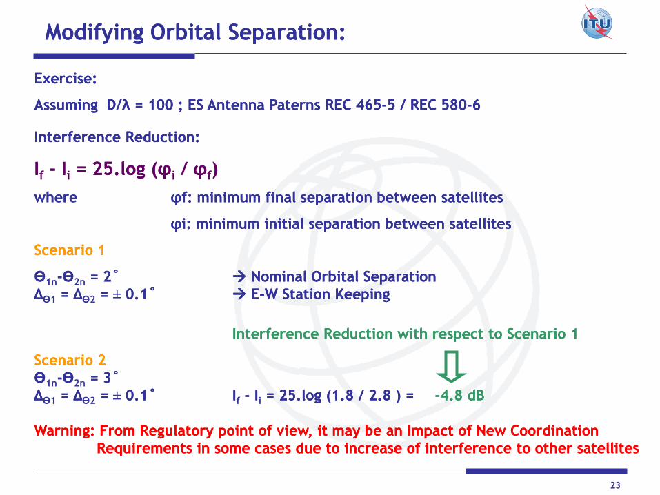
Modifying Orbital Separation:Modifying Orbital Separation:
Exercise:Exercise:
Assuming D/λ = 100 ; ES Antenna Assuming D/λ = 100 ; ES Antenna PaternsPaterns REC 465REC 465--5 / REC 5805 / REC 580--66
Interference Reduction: Interference Reduction:
IIf -- IIi = 25.log (= 25.log (φφi / φφf))
wherewhere φfφf: minimum final separation between satellites: minimum final separation between satellites
φiφi: minimum initial separation between satellites: minimum initial separation between satellites
Scenario 1Scenario 1
ӨӨ1n--ӨӨ2n = 2˚= 2˚ Nominal Orbital SeparationNominal Orbital Separation
ΔΔӨ1 = Δ= ΔӨ2 = = ±± 0.1˚0.1˚ EE--W Station KeepingW Station Keeping
Interference Interference Reduction with respect to Scenario 1Reduction with respect to Scenario 1
Scenario 2Scenario 2
ӨӨ1n--ӨӨ2n = 3˚= 3˚
ΔΔӨ1 = Δ= ΔӨ2 = = ±± 0.1˚0.1˚ IIf -- IIi = 25.log (1.8 / 2.8 ) == 25.log (1.8 / 2.8 ) = --4.8 4.8 dBdB
Warning: From Regulatory point of view, it may be an Impact of New CoordinationWarning: From Regulatory point of view, it may be an Impact of New Coordination
Requirements in some cases due to increase of interference to other satellitesRequirements in some cases due to increase of interference to other satellites

BR / SSD / SNP 24
Gain (phi)
-20
-10
0
10
20
30
40
50
GroundGround SegmentSegment: : ImprovingImproving thethe EarthEarth StationStation RadiationRadiation PatternPattern
Antenna Radiation Patterns Comparison
Sidelobes
Gain (phi)
-20
-10
0
10
20
30
40
50
60
0.01 0.1 1 10 100
Phi [deg]
G [
dB
i]
AP8 REC-465-5 A - 25 LOG (phi) REC-580-6 ABCD log

25
Changing the Earth Station Antenna Diameter:Changing the Earth Station Antenna Diameter:
Gain (phi)
-20
-10
0
10
20
30
40
50
60
0.01 0.1 1 10 100
Phi [deg]
G [
dB
i]Antenna A Antenna B
Ga max [dBi]= 43.2
Gb max [dBi]= 56
Antenna A
G1 = 23.34
Phi m = 1.50
D/L = 59.40
Phi r = 1.68
Phi b= 47.86
Beamwidth= 1.17
Antenna B
G1 = 35.21
Phi m = 0.35
D/L = 259.28
Phi r = 0.56
Phi b= 47.86
Beamwidth= 0.27
REFERENCES - COMMENTS:
Antenna A= Typical 1.2M
Antenna B= Typical 13M
Mainlobe and NearMainlobe and Near--SidelobesSidelobes
RECREC--580580--6 Antenna Pattern6 Antenna Pattern

26
ReorganizingReorganizing distributiondistribution of of differentdifferent typestypes of of carriercarrier
To identify diferent types of carriers such as:
TT&C
Analog TV/FM
Digital Data
To consider their characteristics of diversity in terms of BW,
Max. Power and spectral density distribution.
To group them in the frequency domain taking into account
the distribution of similar carriers used by neighboring
satellites.
Off-axis eirp masks associated to type of carriers and
frequency bands, as well as operational restrictions or
relaxations, may be agreed during the coordination process.

27
How to Optimize a Filing to be submitted to ITU ?How to Optimize a Filing to be submitted to ITU ?
Goal ? Favorable Findings
+ Realistic Info To Ensure Recording
+ Accuracy MIFR
Positive Cycle for current & future networks
Administrations are free to choose the way to organize a filing
Coordination Request: -needs certain flexibility of parameters
-may be a General Approach
-specific
Notification: -accurate parameters
-realistic

28
Filing is Group StructuredFiling is Group Structured
Diversity of: Beam/Service Areas Frequencies Emissions Earth Stations

29
Reorganize Filing considering diversity of frequency Reorganize Filing considering diversity of frequency
assignments and respective progress in coordination assignments and respective progress in coordination
For example: To split groups of frequency assignments by
Group 11 SA 1 Coord. Completed Fav. Finding MIFR
-Beam/Service Areas
Group 12 SA 2 Coord. Not Completed Further progress
is required
-Frequencies ( similar process )
-Emissions ( similar process )
Group 21 Typical 9m Coord. Completed Fav. Finding MIFR
-Earth Stations
Group 22 Typical 1.2m Coord.Not Completed Further progress
is required
Remarks: locating worst cases in separated groups will ensure recording
of successfully coordinated frequency assignments.

28
References:
Some Useful Recommendations:
ITU-R S.741-2 Carrier-to-interference calculations between networks in the FSS.
ITU-R S.740 Technical coordination methods for fixed-satellite networks
Rules of Procedure of Radio Regulations Board associated to C/I analysis under 11.32A
ITU-R SM.1132 General principles and methods for sharing between
radiocommunication services or between radio stations
ITU-R S.738 Procedure for determining if coordination is required between
geostationary-satellite networks sharing the same frequency bands
UIT-R S.580-6 Radiation diagrams for use as design objectives for antennas of earth
stations operating with geostationary satellites UIT-R S.465-5 Reference radiation pattern of earth station antennas in the fixed-
satellite service for use in coordination and interference assessment in the frequency range from 2 to 31 GHz
UIT-R S.1855 Alternative reference radiation pattern for earth station antennas used with satellites in the geostationary-satellite orbit for use in coordination and/or interference assessment in the frequency range from 2 to 31GHz
UIT-R SF.766 Methods for determining the effects of interference on the performance and the availability of terrestrial radio-relay systems and systems in the fixed-satellite service
Appendix 8 to Radio Regulations (Volume 2 of RR) Handbook on Satellite Communications – ITU, Wiley

31
Questions?Questions?
Thank You !Thank You !