sukhoi su31 - manuals.hobbico.commanuals.hobbico.com/hca/hcaa2090-manual.pdf · optional supplies...
TRANSCRIPT

ASSEMBLY INSTRUCTIONS
Entire Contents © Copyright 2004 HCAZ3047 for HCAA2090 V1.0
Wingspan: 61 in [1550mm]Wing Area: 708 sq in [45.7 dm2]Weight: 7.5 - 8.5 lb [3400 - 3850g] Wing Loading: 24 - 28oz/sq ft [73 - 85 g/dm2] Length: 51.5 in [1310mm]Radio: Four-channel with 5 servosEngine: .50 - .75 cu in [8 - 12cc] two-stroke,
.70 - .91 cu in [11. 5 - 15cc] four-stroke
Hobbico® guarantees this kit to be free from defects inboth material and workmanship at the date of purchase.This warranty does not cover any component partsdamaged by use or modification. In no case shallHobbico’s liability exceed the original cost of thepurchased kit. Further, Hobbico reserves the right tochange or modify this warranty without notice.
In that Hobbico has no control over the final assembly ormaterial used for final assembly, no liability shall beassumed nor accepted for any damage resulting from theuse by the user of the final user-assembled product. Bythe act of using the user-assembled product, the useraccepts all resulting liability.
If the buyer is not prepared to accept the liabilityassociated with the use of this product, the buyer isadvised to return this kit immediately in new and unusedcondition to the place of purchase.
To make a warrantyclaim, send the defectivepart or item to HobbyServices at this address.
Include a letter stating your name, return shipping address, asmuch contact information as possible (daytime telephonenumber, fax number, e-mail address), a detailed descriptionof the problem and a photocopy of the purchase receipt.Upon receipt of the package the problem will be evaluatedas quickly as possible.
READ THIS MANUAL BEFORESTARTING CONSTRUCTION. IT CONTAINS IMPORTANT
INSTRUCTIONS AND WARNINGSCONCERNING THE ASSEMBLY
AND USE OF THIS MODEL.
WARRANTY
Hobby Services3002 N. Apollo Dr. Suite 1
Champaign IL 61822USA
1610 Interstate DriveChampaign, Illinois(217) 398-8970 ext. 2
SUKHOI SU31SUKHOI SU31.50 - .91 .50 - .91 ARFARF
™

2
TECHNICAL UPDATES . . . . . . . . . . . . . . . . . . .2AMA . . . . . . . . . . . . . . . . . . . . . . . . . . . . . . . .2SAFETY PRECAUTIONS . . . . . . . . . . . . . . . . . .2HARDWARE AND ACCESSORIES . . . . . . . . . . .3ADDITIONAL ITEMS REQUIRED . . . . . . . . . . .3
Optional Supplies and Tools . . . . . . . . . . . . .4IMPORTANT BUILDING NOTES . . . . . . . . . . .4KIT INSPECTION . . . . . . . . . . . . . . . . . . . . . .5KIT CONTENTS . . . . . . . . . . . . . . . . . . . . . . . .5ORDERING REPLACEMENT PARTS . . . . . . . . .6REPLACEMENT PARTS LIST . . . . . . . . . . . . . . .6PREPARATIONS . . . . . . . . . . . . . . . . . . . . . . .6ASSEMBLE THE WING . . . . . . . . . . . . . . . . . . .7
Install the Ailerons . . . . . . . . . . . . . . . . . . . .7Install the Aileron Servos and Pushrods . . . . .7Join the Wings . . . . . . . . . . . . . . . . . . . . . . .9
ASSEMBLE THE FUSELAGE . . . . . . . . . . . . . . .11Install the Stab, Elevators and Rudder . . . . .11Install the Landing Gear . . . . . . . . . . . . . . .12Install Engine, Fuel Tank & Throttle Servo . . .13Mount the Cowl . . . . . . . . . . . . . . . . . . . . .15Install the Radio System . . . . . . . . . . . . . . .17
FINISHING TOUCHES . . . . . . . . . . . . . . . . . .19GET THE MODEL READY TO FLY . . . . . . . . . .19
Check the Control Directions . . . . . . . . . . .19Set the Control Throws . . . . . . . . . . . . . . . .19Balance the Model (C.G.) . . . . . . . . . . . . . .20Balance the Model Laterally . . . . . . . . . . . .20
PREFLIGHT . . . . . . . . . . . . . . . . . . . . . . . . . .21Identify Your Model . . . . . . . . . . . . . . . . . .21Charge the Batteries . . . . . . . . . . . . . . . . . .21Balance Propellers . . . . . . . . . . . . . . . . . . .21Ground Check . . . . . . . . . . . . . . . . . . . . . .21Range Check . . . . . . . . . . . . . . . . . . . . . . .21
ENGINE SAFETY PRECAUTIONS . . . . . . . . . .22AMA SAFETY CODE . . . . . . . . . . . . . . . . . . .22CHECK LIST . . . . . . . . . . . . . . . . . . . . . . . . .23FLYING . . . . . . . . . . . . . . . . . . . . . . . . . . . . .23
Takeoff . . . . . . . . . . . . . . . . . . . . . . . . . . . .24Flight . . . . . . . . . . . . . . . . . . . . . . . . . . . . .24Landing . . . . . . . . . . . . . . . . . . . . . . . . . . .24
For the latest technical updates or manualcorrections to the Hobbico Sukhoi SU31 visit theHobbico web site at www.hobbico.com. Open the“Airplanes” link, then select the Hobbico SukhoiSU31 .50 -.91 ARF. If there is new technicalinformation or changes to this model a “technotice” box will appear in the upper left corner ofthe page.
We urge you to join the AMA (Academy of ModelAeronautics) and a local R/C club. The AMA is thegoverning body of model aviation and membership isrequired to fly at AMA clubs. Though joining the AMAprovides many benefits, one of the primary reasons tojoin is liability protection. Coverage is not limited toflying at contests or on the club field. It even applies toflying at public demonstrations and air shows. Failureto comply with the Safety Code (excerpts printed in theback of the manual) may endanger insurance coverage.Additionally, training programs and instructors areavailable at AMA club sites to help you get started theright way. There are over 2,500 AMA chartered clubsacross the country. Contact the AMA at the address ortoll-free phone number below:
5151 East Memorial DriveMuncie, IN 47302-9252
Tele. (800) 435-9262Fax (765) 741-0057
Or via the Internet at:http://www.modelaircraft.org
IMPORTANT!!!Two of the most important things you can do topreserve the radio controlled aircraft hobby are toavoid flying near full-scale aircraft and avoid flyingnear or over groups of people.
1. Your Hobbico Sukhoi SU31 should not beconsidered a toy, but rather a sophisticated, workingmodel that functions very much like a full-size airplane.Because of its performance capabilities, the HobbicoSukhoi SU31, if not assembled and operated correctly,could possibly cause injury to yourself or spectatorsand damage to property.
2. You must assemble the model according to theinstructions. Do not alter or modify the model, asdoing so may result in an unsafe or unflyable model. Ina few cases the instructions may differ slightly from thephotos. In those instances the written instructionsshould be considered as correct.
Protect your model, yourself &others... Follow these Important
Safety Precautions
AMA
TECHNICAL UPDATES
TABLE OF CONTENTS

3
3. You must take time to build straight, true and strong.
4. You must use an R/C radio system that is in first-class condition, and a correctly sized engine andcomponents (fuel tank, wheels, etc.) throughout thebuilding process.
5. You must correctly install all R/C and othercomponents so that the model operates correctly onthe ground and in the air.
6. You must check the operation of the model beforeevery flight to insure that all equipment is operating andthat the model has remained structurally sound. Besure to check clevises or other connectors often andreplace them if they show any signs of wear or fatigue.
7. If you are not an experienced pilot or have notflown this type of model before, we recommendthat you get the assistance of an experienced pilotin your R/C club for your first flights.
8. While this kit has been flight tested to exceednormal use, if the plane will be used for extremelyhigh stress flying, the modeler is responsible fortaking steps to reinforce the high stress points.
9. WARNING: The cowl included in this kit is madeof fiberglass, the fibers of which may cause eye,skin and respiratory tract irritation. Never blow intothe cowl to remove fiberglass dust, as the dust willblow back into your eyes. Always wear safetygoggles, a particle mask and rubber gloves whengrinding, drilling and sanding fiberglass parts.Vacuum the parts and the work area thoroughlyafter working with fiberglass parts.
Remember: Take your time and follow theinstructions to end up with a well-built model.
This is a partial list of items required to finish theHobbico Sukhoi SU31 that may require planning ordecision making before starting to build. Ordernumbers are provided in parentheses.
RADIO EQUIPMENT
❏ Four channel radio❏ Four 54 oz-in servos and one 30 oz-in servo❏ Two 6” [150mm] servo extensions
(HCAM2701 for Futaba)❏ Y-harness (HCAM2751 for Futaba)❏ 500 mAh battery or greater
ENGINE RECOMMENDATIONS
We have installed both a two-and a four-stroke enginein our prototypes. The two-stroke engine with astandard muffler or with most Pitts style mufflersrequires much of the cowl to be cut away, while thefour-stroke maintains most of the integrity of the cowl.If a more “scale“ look is desired we recommend thefour-stroke engine over the two-stroke.
50 - .75 cu in [8 - 12cc] two-stroke, .70 - .91 [11. 5 - 15cc] four-stroke
❏ R/C foam rubber (1/4” [6mm] - HCAQ1000,or 1/2” [13mm] - HCAQ1050)
❏ 1/2 oz. [15g] Thin Pro™ CA (GPMR6001)❏ 1 oz. [30g] Medium Pro CA+ (GPMR6008)❏ Pro 30-minute epoxy (GPMR6047)❏ Pro 6-minute epoxy (GPMR6045)❏ Drill bits: 1/16” [1.6mm], 5/64” [2mm], 1/8”
[3.2mm], 3/16” [4.8mm]. ❏ #1 Hobby knife (HCAR0105)❏ #11 blades (5-pack, HCAR0211)❏ Top Flite® MonoKote® sealing iron (TOPR2100) ❏ CA applicator tips (HCAR3780)❏ R/C-56 canopy glue (JOZR5007)❏ Threadlocker thread locking cement
(GPMR6060)
ADDITIONAL ITEMS REQUIRED
HARDWARE & ACCESSORIES
We, as the kit manufacturer, provide you with atop quality, thoroughly tested kit andinstructions, but ultimately the quality andflyability of your finished model depends on howyou build it; therefore, we cannot in any wayguarantee the performance of your completedmodel, and no representations are expressed orimplied as to the performance or safety of yourcompleted model.

OPTIONAL SUPPLIES AND TOOLS
Here is a list of optional tools mentioned in themanual that will help you build the HobbicoSukhoi SU31.
❏ 2 oz. [57g] spray CA activator (GPMR6035)❏ CA debonder (GPMR6039)❏ Epoxy brushes (6, GPMR8060)❏ Mixing sticks (50, GPMR8055)❏ Mixing cups (GPMR8056)❏ Curved-tip canopy scissors for trimming plastic
parts (HCAR0667)❏ Robart Super Stand II (ROBP1402)❏ 18” x 24” [460 x 610mm] Builder’s Cutting
Mat (HCAR0455)❏ Hobbico Duster™ can of compressed air
(HCAR5500)❏ Masking tape (TOPR8018)❏ Denatured alcohol (for epoxy clean up)❏ Switch & Charge Jack Mounting Set
(GPMM1000)❏ Rotary tool such as Dremel®
❏ Rotary tool reinforced cut-off wheel(GPMR8200)
❏ Servo horn drill (HCAR0698)❏ AccuThrow™ Deflection Gauge (GPMR2405) ❏ CG Machine™ (GPMR2400)❏ Precision Magnetic Prop Balancer™
(TOPQ5700)
· When you see the term test fit in theinstructions, it means that you should firstposition the part on the assembly without usingany glue, then slightly modify or custom fit thepart as necessary for the best fit.
· Whenever the term glue is written you shouldrely upon your experience to decide what typeof glue to use. When a specific type of adhesiveworks best for that step, the instructions willmake a recommendation.
· Whenever just epoxy is specified you may useeither 30-minute (or 45-minute) epoxy or 6-minute epoxy. When 30-minute epoxy isspecified it is highly recommended that youuse only 30-minute (or 45-minute) epoxy,because you will need the working time and/orthe additional strength.
· Photos and sketches are placed before the stepthey refer to. Frequently you can study photosin following steps to get another view of thesame parts.
· The stabilizer and wing incidences and enginethrust angles have been factory-built into thismodel. However, some technically-mindedmodelers may wish to check thesemeasurements anyway. To view thisinformation visit the web site atwww.hobbico.com and click on “TechnicalData.” Due to manufacturing tolerances whichwill have little or no effect on the way yourmodel will fly, please expect slight deviationsbetween your model and the published values.
METRIC CONVERSIONS
COMMON ABBREVIATIONS
Fuse = FuselageStab = Horizontal Stabilizer
Fin = Vertical FinLE = Leading EdgeTE = Trailing EdgeLG = Landing GearPly = Plywood
" = Inchesmm = Millimeters
SHCS = Socket Head Cap Screw
1/64" = .4mm1/32" = .8mm1/16" = 1.6mm3/32" = 2.4mm
1/8" = 3.2mm5/32" = 4mm3/16" = 4.8mm
1/4" = 6.4mm3/8" = 9.5mm1/2" = 12.7mm5/8" = 15.9mm3/4" = 19mm
1" = 25.4mm2" = 50.8mm3" = 76.2mm6" = 152.4mm
12" = 304.8mm15" = 381mm18" = 457.2mm21" = 533.4mm24" = 609.6mm30" = 762mm36" = 914.4mm
To convert inches to millimeters,multiply inches by 25.4 (25.4mm = 1")
IMPORTANT BUILDING NOTES
4

5
11
12
13
14
1
2
3
4
5
6
7
8
9
10
KIT INSPECTION
KIT CONTENTS
Before starting to build, take an inventory of this kit to make sure it is complete, and inspect the parts tomake sure they are of acceptable quality. If any parts are missing or are not of acceptable quality, or if youneed assistance with assembly, contact Product Support. When reporting defective or missing parts, usethe part names exactly as they are written in the Kit Contents list.
Hobbico Product Support • 3002 N Apollo Drive, Suite 1 • Champaign, IL 61822Telephone: (217) 398-8970, ext. 2 • Fax: (217) 398-7721
E-mail: [email protected]
Items photographed
1. Fuselage & Cowl2. Fuel tank3. Dummy engine4. Left wing5. Landing gear6. Wheels7. Wheel pants8. Tail wheel assembly9. Belly pan
10. Canopy11. Right wing12. Stab & elevators13. Fin & Rudder14. Engine Mount
Qty2 15x15x15mm hardwood block2 15x15x10mm hardwood block 2 155mm length of Velcro®
2 3mm plywood wing joiner 1 Plywood wing bolt plate 5 Nylon control horns and plates 17 Hinges 5 Nylon clevises 4 Faslinks 2 4 x 40mm machine screw 2 4 x 35mm machine screw 4 4 x 25mm machine screw 4 4 x 19mm machine screw 4 4 x 15mm machine screw 10 4mm flat washer 8 4mm lock washers 2 4mm nuts 3 3 x 5mm machine screw 2 4mm wheel collar 4 2 x 20mm machine screw
Qty6 2 x 15mm machine screw 3 2 x 7mm sheet metal screw 1 screw lock connector 1 2mm thumb nut 1 2mm washer for screw-lock
connector 1 300mm nylon pushrod 3 2 x 710 mm pushrod wire 1 1mm wire 4 4mm blind nuts 4 3 x 12mm cowl mounting bolts 1 6 x 6 x 127mm balsa stick 1 2.5” (approximately 64mm)
red plastic spinner 1 400mm fuel tubing6 4mm lock nuts 5 Silicone clevis retainers 2 2 x 80mm pushrod wire
Parts not photographed

Replacement parts for the Sukhoi SU 31 ARF areavailable using the order numbers in theReplacement Parts List that follows. The fastest,most economical service can be provided by yourhobby dealer or mail-order company.
To locate a hobby dealer, visit the Hobbico web site atwww.hobbico.com. Choose “Where to Buy” at thebottom of the menu on the left side of the page. Followthe instructions provided on the page to locate a U.S.,Canadian or International dealer. If a hobby shop is notavailable, replacement parts may also be ordered fromTower Hobbies at www.towerhobbies.com or bycalling toll free (800) 637-6050.
Parts may also be ordered directly from Hobby Servicesby calling (217) 398-0007, or via facsimile at (217) 398-7721, but full retail prices and shipping andhandling charges will apply. Illinois and Nevadaresidents will also be charged sales tax. If ordering viafax, include a Visa® or MasterCard® number andexpiration date for payment.
Mail parts orders and payments by personal checkto:
Hobby Services3002 N Apollo Drive, Suite 1
Champaign IL 61822
Be certain to specify the order number exactly aslisted in the Replacement Parts List. Payment bycredit card or personal check only; no C.O.D.
If additional assistance is required for any reasoncontact Product Support by e-mail [email protected], or by telephone at(217) 398-8970.
OrderNumber Description How to purchaseHCAA3630 . . . . . Wing . . . . . . Hobby SupplierHCAA3631 . . Fuse/belly pan . . . Hobby SupplierHCAA3633 . . . Tail Surfaces . . . Hobby SupplierHCAA3632. . . . . . Cowl . . . . . . Hobby SupplierHCAA3635. . . . . Canopy . . . . . Hobby SupplierHCAA3636 . . Landing Gear . . . Hobby SupplierHCAA3634 . . Wheel Fairings. . . Hobby SupplierHCAA3637 . . Dummy Engine . . Hobby SupplierMissing pieces. . . . . . . . . . . . . . Product SupportInstruction manual. . . . . . . . . . . Product SupportFull-size plans . . . . . . . . . . . . . . . Not available
1. If you have not done so already, remove themajor parts of the kit from the box and inspect fordamage. If any parts are damaged or missing,contact Product Support at the address or telephonenumber listed in the “Kit Inspection” section onpage 5.
2. Remove the tape and separate the ailerons andflaps from the wing and the elevators from the stab.Use a covering iron with a covering sock on highheat to tighten the covering if necessary. Applypressure over sheeted areas to thoroughly bond thecovering to the wood.
When ready to fly, you'll need some additionalequipment to fuel the plane and start the engine.The most important items include an electric starter,12 volt battery, or chicken stick, fuel pump (electricor hand-crank), fueling lines and fittings and a 1.5volt glow plug igniter. Your flight instructor willprobably let you share his equipment for a while,but eventually you'll need your own. Visit your localhobby dealer or see the Hobbico catalog for a fullselection, descriptions and pricing.
PREPARATIONS
REPLACEMENT PARTS LIST
ORDERING REPLACEMENT PARTS
6

INSTALL THE AILERONS
Do the right wing first so your work matches thephotos the first time through.
❏ ❏ 1. Install a hinge into each of the four hingeslots in the aileron. Be sure the slit in the hinge isperpendicular to the leading edge of the aileron.
❏ ❏ 2. Apply six drops of thin CA to the top andbottom of each hinge waiting a few secondsbetween drops to allow the CA to soak in. Do notuse CA accelerator. After the CA has fully hardened,test the hinges by pulling on the aileron.
❏ ❏ 3. Locate the opening for the servo on the bottomof the wing. Cut the covering from the opening.
❏ ❏ 4. On the top of the wing locate the 1/2”[13mm] hole and cut the covering away.
❏ 5. Repeat steps 1 - 4 for the left wing.
INSTALL THE AILERON SERVOS AND PUSHRODS
❏ 1. Installing the servos in the wing will requirethe use of one 6” [152mm] servo extension for eachaileron. One Y-harness connector is required and isused to allow the aileron servos to plug into one slotin your receiver. You may have a computer radiothat allows you to plug the servos into separate slotsand mix them together through the radio transmitter.If you choose to mix them with the radio rather thanthe Y-harness, refer to the instructions with yourparticular brand of radio. Attach the servo extensionto the aileron servo. Secure the connectors togetherusing a large piece of heat shrink tubing or tape.
❏ ❏ 2. Located in the wing in the servo compartment,a string is taped to the wing skin. Tie the string to the endof the servo wire. Pull the servo wire through the wingwith the string. Feed the servo wire out the hole in thetop of the wing center section. Tape the servo wire tothe wing to prevent it from falling back into the wing.
ASSEMBLE THE WING
7
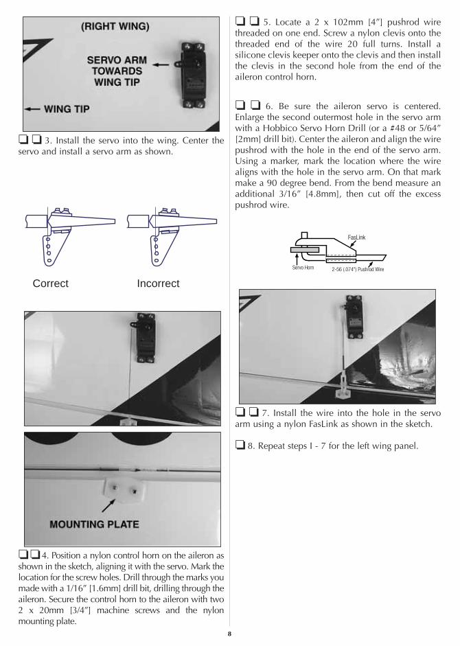
❏ ❏ 3. Install the servo into the wing. Center theservo and install a servo arm as shown.
❏ ❏ 4. Position a nylon control horn on the aileron asshown in the sketch, aligning it with the servo. Mark thelocation for the screw holes. Drill through the marks youmade with a 1/16” [1.6mm] drill bit, drilling through theaileron. Secure the control horn to the aileron with two2 x 20mm [3/4”] machine screws and the nylonmounting plate.
❏ ❏ 5. Locate a 2 x 102mm [4”] pushrod wirethreaded on one end. Screw a nylon clevis onto thethreaded end of the wire 20 full turns. Install asilicone clevis keeper onto the clevis and then installthe clevis in the second hole from the end of theaileron control horn.
❏ ❏ 6. Be sure the aileron servo is centered.Enlarge the second outermost hole in the servo armwith a Hobbico Servo Horn Drill (or a #48 or 5/64”[2mm] drill bit). Center the aileron and align the wirepushrod with the hole in the end of the servo arm.Using a marker, mark the location where the wirealigns with the hole in the servo arm. On that markmake a 90 degree bend. From the bend measure anadditional 3/16” [4.8mm], then cut off the excesspushrod wire.
❏ ❏ 7. Install the wire into the hole in the servoarm using a nylon FasLink as shown in the sketch.
❏ 8. Repeat steps I - 7 for the left wing panel.
Correct Incorrect
8

JOIN THE WINGS
❏ 1. Locate two hardwood wing joiners. Glue themtogether with 6-minute epoxy, forming one 1/4” [6mm]wing joiner. Set the joiner aside until the glue cures.
❏ 2. Test fit the joiner into both wing halves, makingsure that it is not too tight. Sand the joiner as neededto get a good fit.
❏ 2. Apply 30-minute epoxy to the wing joiner, thejoiner pocket in both wing panels and the root rib ofeach wing panel. Push the wing panels together andhold them in place with masking tape. Before the gluecures, set the wing flat on your bench and measure thedihedral. The distance from the top of the bench to thecenter of the wing as measured at the wing tip should beapproximately 2-3/8” [60mm]. Block the wingtip upwhile the glue cures. Note: Due to productiontechniques there may be some variance in the actualdihedral of each model. 1/4” [6mm] more or less thanthis dimension is acceptable.
❏ 3. Set the wing aside allowing the glue to cure.
❏ 4. Cut the covering from the wing bolt holes onboth the top and bottom of the wing.
❏ 5. Place the plywood wing bolt mounting plate inposition on the bottom of the wing, centered on thewing bolt holes. Using a fine-tip, felt-tip marker,trace the outline of the plate onto the wing. Use asharp #11 hobby knife or use the Expert Tip thatfollows to cut the covering from the wing along thelines you have marked. Use care to cut only into thecovering and not into the wood.
2-3/8" [60mm]
9

Use a soldering iron to cut the covering from the stab.The tip of the soldering iron doesn't have to be sharp, buta fine tip does work best. Allow the iron to heat fully.Use a straightedge to guide the soldering iron at a ratethat will just melt the covering and not burn into thewood. The hotter the soldering iron, the faster it musttravel to melt a fine cut. Peel off the covering.
❏ 6. Glue the plywood wing bolt plate to the wing.
❏ 7. From the top of the wing, drill through the twowing bolt holes and through the plywood wing boltplate using a 5/32” [4mm] drill bit.
❏ 8. Mount the wing to the fuselage with two 4 x 35mm[1-3/8”] machine screws and two 4mm washers.
❏ 9. Cut the covering from the wing bolt holes inthe belly pan. Place the belly pan onto the bottom ofthe wing, aligning it with the fuselage. Mark theoutline of the belly pan onto the fuselage with a fine-tip, felt-tip marker.
❏ 10. Just inside the lines you have made, cut away a1/4” [6mm] strip of covering. Remove a 1/4” [6mm] stripfrom the front and rear of the wing as well.
❏ 11. Glue the belly pan to the wing. Tape the bellypan in place while the glue cures. Once cured,remove the wing from the fuselage.
❏ 12. If you will be using a “Y” harness for theailerons, attach the “Y” harness to the aileron servos.Secure the connectors together using a large piece ofheat shrink tubing, tape or other method.
HHHHooootttt TTTTiiiippppHow to cut covering from balsa
10

INSTALL THE STAB, ELEVATORS AND RUDDER
❏ 1. Cut the covering away from the stab openingon both sides of the fuselage. On the left side of thefuselage cut away the covering from the elevator andrudder pushrod openings. On the right side cut thecovering from the elevator and antenna openings.
❏ 2. Mount the wing to the fuselage the test fit the stabinto the opening in the back of the fuselage. Stand backand look at the stab in relation to the wing. The stabshould be parallel with the wing. If not, sand the stabsaddle until the stab and wing align.
❏ 3. Measure the distance from the tip of the stab tothe tip of each wing. Adjust the position of the stabuntil both are equal.
❏ 4. Once you are satisfied with the fit andpositioning of the stab, use a fine, felt-tip marker andtrace the outline of the fuselage onto the top andbottom of the stab. Cut the center section of thecovering from the top and bottom of the stab usingthe same technique used for the wing.
❏ 5. When satisfied with the fit of the stab, use thinCA with a CA applicator tip to wick glue into the stabsaddle. Apply the glue to the top, bottom and bothsides of the fuselage. Allow the glue to fully curebefore moving. After the glue has cured remove thewing from the fuselage.
“Hint”: Do not use any accelerator. This will most likelycause the glue to get a white haze on the fuselage andstab. Allow the plane to sit for approximately 5 minutesuntil the glue is completely cured.
❏ 6. Install the two elevator halves using the samemethod used for the ailerons. Once you are satisfiedwith the positioning of the elevators, glue them in placewith thin CA the same as was done on the ailerons.
ASSEMBLE THE FUSELAGE
11

❏ 7. Install the fin into the slot in the top of thefuselage. Use a fine, felt-tip marker and trace theoutline of the fuselage onto the fin. Cut the coveringfrom the fin using the same technique used on thewing and stab.
❏ 8. Apply epoxy on the fin and in the slot in thefuselage. Check to make sure the fin is perpendicular tothe stab. If necessary, use masking tape to pull the fininto position. Set the fuselage aside until the glue cures.
❏ 9. Insert three hinges into the rudder. Then slide therudder onto the fin. Apply thin CA onto the hinges thesame as was done with the other control surfaces.
This completes the installation of the tail surfaces.You will finish the installation of the control hornsand pushrods when you do the radio installation.
INSTALL THE LANDING GEAR
❏ 1. Attach the landing gear to the fuselage withfour 4 x 15mm [9/16”] machine screws. Apply acouple of drops of thread locker to the bolts beforeinstalling them into the fuselage.
❏ 2. Assemble the wheel and wheel pant as shown.Do this for both wheels.
4 x 40mmMACHINESCREW
4mmNUT
4mmLOCK NUT
12

❏ 3. Slide the black nylon mounting flange onto thetail wheel wire. Then bend the wire as shown.
❏ 4. Make a 90 degree bend 1” [25mm] from thepivot point of the tail wheel wire.
❏ 5. Place the tail wheel assembly onto the bottom ofthe fuselage and mark the location where the wire willgo through the rudder. Drill a 1/16” [1.6mm] hole intothe bottom of the rudder; slide the wire into the bottom
of the rudder. Drill a 1/16” [1.6mm] hole into thefuselage through each of the mounting holes in thenylon mounting flange. Secure the flange to the fuselagewith three 2 x 7mm [5/16”] sheet metal screws.
INSTALL ENGINE, FUEL TANK & THROTTLE SERVO
❏ 1. The top of the engine mount can be identifiedby the angled bevel. Be sure when mounting theengine in the following steps that you mount theengine on the top of this rail.
❏ 2. Mount the engine to the two engine mounthalves. The distance from the front of the engine thrustwasher to the firewall should be 5-1/4” [133mm]. Placethe engine on one of the mounts. Mark the location forthe mounting holes onto the engine mount rail. On themarks, drill through the rail with a 5/32” [4mm] drill.Secure the engine to the rail with 4 x 25mm [1”]machine screws and 4mm lock nuts. Do this for bothengine mount halves.
13

❏ 3. The engine will be mounted to the firewall onits side (see photograph at step 7). On the firewallthere are reference marks. On the engine mountthere are also reference marks.
❏ 4. Align the reference marks of the engine mountwith the lines on the firewall and center the sides of theengine mount with the reference lines on the firewall.
❏ 5. With the engine properly positioned mark theengine mount holes onto the firewall. Remove theengine from the firewall and drill through each of themarks with a 3/16” [4.8mm] drill.
❏ 6. Position a 4mm blind nut behind one of theholes you drilled in the firewall. Insert a 4mm [5/32”]machine screw and washer into the hole, threadingit into the 4mm blind nut. Tighten the bolt until theblind nut is pulled tight against the backside of thefirewall. Remove the bolt and repeat this for each ofthe three remaining holes.
❏ 7. Install the engine mount to the firewall withfour 4 x 19mm [3/4”] machine screws, 4mm lockwasher and 4mm flat washer.
❏ 8. Assemble the fuel tank as shown. If you will beusing a fuel valve (not included) for filling the tankrather than filling the tank by removing the line fromthe carburetor, install it in the fuel line following theinstructions included with the valve.
❏ 9. Install the fuel tank into the fuselage, andthrough the hole in the firewall. From the 6 x 6 x127mm [5”] balsa stick, cut the stick to fit and glueit in place behind the tank.
FUEL TANKPRESSURE
TAP TOMUFFLER
TO NEEDLEVALVE
FIREWALL
SILICONEFUEL LINE
FUEL CLUNK
FUELPIPE
14

❏ 10. Install fuel tubing from the tank to the engine andmuffler, following the instructions with your engine.
❏ 11. Drill a 5/64” [2mm] hole through the firewall inline with the carburetor on your engine. Insert the 2 x300mm [12”] nylon throttle tube guide through thehole and into the radio compartment. Apply glue to theend of the nylon pushrod, gluing it to the firewall.
❏ 12. Mount the throttle servo on the left side of theservo tray as shown. (Refer to the picture on page 18,“Install the Radio System”, step 7 for the placementof all of the servos in the fuselage). Install the screw-lock connector onto the servo arm, securing it with a2mm washer and nut. Apply a drop of thread lockerto the nut to prevent it from coming loose. Slide the1mm pushrod wire into the tube and through thehole in the screw-lock connector. Install the throttlearm onto the z-bend on the end of the pushrod wire.When the pushrod wire is secure on the throttle arm,secure the throttle wire to the screw-lock connectorwith a 2 x 2mm [1/16”] bolt.
MOUNT THE COWL
❏ 1. On the right side of the fuselage, mark thelocation for the cowl mounting blocks. For the topmounting block measure from the front of the fuselageback 1-5/8” [40mm] and make a line. Measure up fromthe bottom of the fuselage 3-1/2” [89mm] and make aline intersecting the other line. Place a 15 x 15 x 10mm[5/8” x 5/8” x 3/8”] hardwood block at the intersectionof the two lines. Trace the outline of the block onto thefuselage. At the location of the block, cut the coveringfrom the fuselage.
At the front of the fuselage, measure up from thebottom of the fuselage 3/4” [19mm] and make amark. Place a 15 x 15 x 15mm [5/8” x 5/8” x 5/8”]block on this line, turning the block so the cornersare aligned with the front of the fuselage. Trace theoutline of the block and then cut the covering fromthe fuselage. Glue both blocks to the fuselage with6-minute epoxy. Repeat this procedure for theblocks on the left side of the fuselage.
❏ 2. Next you need to slip the cowl onto thefuselage. Depending on which engine you havechosen to install, you may not be able to slide thecowl over the engine. Most 2-stroke engines areshort enough to allow the cowl to slip over theengine without interference. The O.S.® .91 is a bit tootall for the cowl to slide over but will fit if youremove the valve cover.
❏ 3. For the next step you may find it helpful to havean assistant. Position the cowl so the distance from
15

the firewall to the front of the cowl is 5-3/8”[136mm]. This dimension will properly space theengine when using the spinner included with this kit.If you are using a different spinner or no spinner youmay need to position the cowl further forward orback to properly position the cowl. Place yourspinner and propeller on the engine to be sure youhave the proper spacing required.
❏ 4. Double-check to be sure you have the properspacing for the cowl and that the cowl is centered onthe engine. Have your assistant hold the cowl whileyou mark the location for the cowl mounting screws.(The cowl mounting blocks are easily visible fromthe back of the cowl.)
Begin on the right side of the fuselage first. Drill a 3/32”[2.4mm] hole through the cowl and into the top cowlmounting block. Install a 3mm cowl mounting screwinto the cowl. Double check the positioning of thecowl and then drill the bottom hole. Repeat this for theleft side of the fuselage, checking the position of thecowl after each screw is installed.
❏ 5. Remove the cowl mounting screws and the cowl.Put a couple of drops of thin CA into each of the screwholes to harden the threads. Allow the glue to cure.
❏ 6. Re-install the cowl onto the front of thefuselage. On the cowl, mark the location for theglow plug, needle valve, muffler or any part of theengine that conflicts with the cowl. Using a rotarytool, begin cutting small portions of the cowl,making the holes progressively larger until the cut-out matches your particular engine installation.
❏ 7. Cut the center of the plastic dummy engine tofit around the front of the engine. Leave plenty ofclearance between the dummy engine and theengine thrust washer. The spinner will cover any gapsbetween the two. Mark the location of the enginecylinder and then cut away this area from thedummy engine. Paint the dummy engine with a fuelproof paint. We painted the louvers a light gray andthe engine flat black.
❏ 8. Slip the dummy engine into the cowl and theninstall the cowl onto the fuselage. Position thedummy engine, centering it with the engine. Usingmedium CA glue with a micro-tip on the bottle, tackglue the dummy engine to the cowl. Once thedummy engine is secure to the cowl, remove thecowl and permanently glue the dummy engine inplace by applying a bead of glue to the back of thedummy engine from inside the cowl.
16

INSTALL THE RADIO SYSTEM
1. Locate three 2 x 685mm [27”] pushrod wiresthreaded on one end. Screw a nylon clevis onto thethreaded end of the wires 20 full turns. Install asilicone clevis keeper onto the clevises. Connect anylon control horn onto each of the two clevises.Install the clevis in the second hole from the end ofthe control horn.
❏ 2. Slide two of the wires with clevises attachedinto the openings shown in the photographs.
❏ 3. Position the control horns on the elevators,positioning them the same way as you did with theailerons. Mark the location for the screw holes. Drillthrough the marks you made with a 1/16” [1.6mm]drill bit, drilling through the elevator. Secure thecontrol horn to the aileron with two 2 x 15mm [5/8”]machine screws and the nylon mounting plate.
❏ 4. Insert the third rod into the remaining opening onthe left side of the fuselage. Connect the control horn tothe clevis and attach the control horn to the rudder inthe same way you installed them to the elevators.
❏ 5. Install the rudder servo into the servo tray at theposition shown. Mark the location for the servomounting screws. Drill a 1/16” [1.6mm] hole throughthe marks, drilling through the plywood tray. Insert andthen remove one of the servo mounting screws suppliedwith your radio into each of the four holes you havedrilled. Apply a couple of drops of thin CA to each ofthe holes to harden the threads. After the glue has curedpermanently mount the servo.
❏ 6. Be sure the rudder servo is centered. Enlargethe outermost hole in the servo arm with a HobbicoServo Horn Drill (or a #48 or 5/64” [2mm] drill bit).
17

Center the rudder and align the wire pushrod withthe hole in the end of the servo arm. Use a fine, felt-tip pen to mark the wire where it crosses the holes inthe servo arm. On that mark make a 90 degree bend.From the bend measure an additional 3/16” [4.8mm]and then cut off the excess pushrod wire. Install anylon Faslink to the wire and servo arm.
❏ 7. Install the elevator servo into the servo tray.Position it in line with the elevator pushrods. Mountthe servo using the same procedure used for therudder servo.
❏ 8. Make a bend in the elevator pushrod wires asshown in the photo above.
❏ 9. Screw a 2.5 x 5mm [3/16”] bolt with a smallamount of threadlocker into two 4mm [5/32”] wheelcollars. Slide the wheel collars onto the wires. Alignthe elevators. Tighten the set screws against thewires. Cut the excess wire.
❏ 10. Be sure the elevator servo is centered. Enlarge theoutermost hole in the servo arm with a Hobbico ServoHorn Drill (or a #48 or 5/64” [2mm] drill bit). Center theelevators and align the wire pushrod with the hole in theend of the servo arm. Using a marker, mark the locationwhere the wire aligns with the hole in the servo arm. Onthat mark make a 90 degree bend. From the bendmeasure an additional 3/16” [4.8mm] and then cut offthe excess pushrod wire. Install a nylon Faslink to thewire and servo arm.
❏ 11. Install the battery and receiver as shown.Place 1/4” thick foam under the receiver and battery,holding it in place with the Velcro material includedwith the kit.
❏ 12. Use an arm cut from a servo horn to make anantenna strain relief as shown. Insert the receiverantenna into the white antenna tube. Hold it to thefuselage by placing a small rubber band around thetail wheel and the end of the antenna.
❏ 13. Install the radio switch to the side of thefuselage. Connect the battery to the switch andsecure the ends of the leads with heat shrink tubing,tape or some other method for securing the leads.
18

❏ 1. If you wish to install a pilot, permanently glueit in place in the cockpit.
❏ 2. Trim the canopy on the molded cut lines. Gluethe canopy to the fuselage with RC 56 canopy glue.
❏ 3. Install the propeller that is best suited to your engine.
CHECK THE CONTROL DIRECTIONS
❏ 1. Turn on the transmitter and receiver and centerthe trims. If necessary, remove the servo arms fromthe servos and reposition them so they are centered.Reinstall the screws that hold on the servo arms.
❏ 2. With the transmitter and receiver still on, checkall the control surfaces to see if they are centered. Ifnecessary, adjust the clevises on the pushrods tocenter the control surfaces.
❏ 3. Make certain that the control surfaces and thecarburetor respond in the correct direction as shown
in the diagram. If any of the controls respond in thewrong direction, use the servo reversing in thetransmitter to reverse the servos connected to thosecontrols. Be certain the control surfaces haveremained centered. Adjust if necessary.
SET THE CONTROL THROWS
❏ Use a Great Planes AccuThrow (or a ruler) toaccurately measure and set the control throw of eachcontrol surface as indicated in the chart that follows. Ifyour radio does not have dual rates, we recommendsetting the throws at the low-rate setting.NOTE: The throws are measured at the widest partof the elevators, rudder and ailerons.
IMPORTANT: The Hobbico Sukhoi SU31 hasbeen extensively flown and tested to arrive at thethrows at which it flies best. Flying your model atthese throws will provide you with the greatestchance for successful first flights. If, after youhave become accustomed to the way theHobbico Sukhoi SU31 flies, you would like tochange the throws to suit your taste, that is fine.However, too much control throw could makethe model difficult to control, so remember,“more is not always better.”
Recommended control surface throws
High Rate Low Rate
ELEVATOR 5/8” up 1/2” up[16mm] [13mm]
5/8” down 1/2” down
RUDDER 1-1/2” right 1” right[38mm] [25mm]
1-1/2” left 1” left
AILERONS 3/4” up 1/2” up[19mm] [13mm]
3/4” down 1/2” up4-CHANNEL
TRANSMITTER
TRANSMITTER4-CHANNEL
TRANSMITTER4-CHANNEL
TRANSMITTER4-CHANNEL
GET THE MODEL READY TO FLY
FINISHING TOUCHES
19

BALANCE THE MODEL (C.G.)
At this stage the model should be in ready-to-flycondition with all of the systems in place includingthe engine, landing gear, covering and paint, and theradio system.
❏ 1. Use a felt-tip pen or 1/8” [3mm]-wide tape toaccurately mark the C.G. on the top of the wing onboth sides of the fuselage. The C.G. is located 3-15/16” [100mm] back from the leading edge of thewing at the fuselage side.
❏ 2. With the wing attached to the fuselage, all partsof the model installed (ready to fly) and an emptyfuel tank, place the model upside-down on a GreatPlanes CG Machine, or lift it upside-down at thebalance point you marked.
❏ 3. If the tail drops, the model is “tail heavy” andthe battery pack and/or receiver must be shiftedforward or weight must be added to the nose tobalance. If the nose drops, the model is “nose heavy”and the battery pack and/or receiver must be shiftedaft or weight must be added to the tail to balance. Ifpossible, relocate the battery pack and receiver tominimize or eliminate any additional ballastrequired. If additional weight is required, noseweight may be easily added by using a “spinnerweight” (GPMQ4645 for the 1 oz. [28g] weight, orGPMQ4646 for the 2 oz. [56g] weight). If spinnerweight is not practical or is not enough, use GreatPlanes (GPMQ4485) “stick-on” lead. A good placeto add stick-on nose weight is to the firewall (don’tattach weight to the cowl—it is not intended tosupport weight). Begin by placing incrementallyincreasing amounts of weight on the bottom of thefuse over the firewall until the model balances. Onceyou have determined the amount of weight required,it can be permanently attached. If required, tailweight may be added by cutting open the bottom ofthe fuse and gluing it permanently inside.
Note: Do not rely upon the adhesive on the back ofthe lead weight to permanently hold it in place.Over time, fuel and exhaust residue may soften theadhesive and cause the weight to fall off. Use #2sheet metal screws, RTV silicone or epoxy topermanently hold the weight in place.
❏ 4. IMPORTANT: If you found it necessary to addany weight, recheck the C.G. after the weight hasbeen installed.
BALANCE THE MODEL LATERALLY
❏ 1. With the wing level, have an assistant help youlift the model by the engine propeller shaft and thebottom of the fuse under the TE of the fin. Do thisseveral times.
❏ 2. If one wing always drops when you lift themodel, it means that side is heavy. Balance theairplane by adding weight to the other wing tip. Anairplane that has been laterally balanced will trackbetter in loops and other maneuvers.
This is where your model should balance for thefirst flights. Later, you may wish to experiment byshifting the C.G. up to 1/4” [6mm] forward or1/8” [3mm] back to change the flyingcharacteristics. Moving the C.G. forward mayimprove the smoothness and stability, but themodel may then require more speed for takeoffand make it more difficult to slow for landing.Moving the C.G. aft makes the model moremaneuverable, but could also cause it tobecome too difficult to control. In any case, startat the recommended balance point and do notat any time balance the model outside thespecified range.
More than any other factor, the C.G. (balance point)can have the greatest effect on how a model flies,and may determine whether or not your first flightwill be successful. If you value this model and wishto enjoy it for many flights, DO NOT OVERLOOKTHIS IMPORTANT PROCEDURE. A model that isnot properly balanced will be unstable andpossibly unflyable.
20

IDENTIFY YOUR MODEL
No matter if you fly at an AMA sanctioned R/C clubsite or if you fly somewhere on your own, youshould always have your name, address, telephonenumber and AMA number on or inside your model.It is required at all AMA R/C club flying sites andAMA sanctioned flying events.
CHARGE THE BATTERIES
Follow the battery charging instructions that came withyour radio control system to charge the batteries. Youshould always charge your transmitter and receiverbatteries the night before you go flying, and at othertimes as recommended by the radio manufacturer.
NOTE: Checking the condition of your receiverbattery pack is highly recommended. All batterypacks, whether it’s a trusty pack you’ve just taken outof another model, or a new battery pack you justpurchased, should be cycled, noting the dischargecapacity. Oftentimes, a weak battery pack can beidentified (and a valuable model saved!) bycomparing its actual capacity to its rated capacity.Refer to the instructions and recommendations thatcome with your cycler. If you don’t own a batterycycler, perhaps you can have a friend cycle yourpack and note the capacity for you.
BALANCE PROPELLERS
Carefully balance your propeller and sparepropellers before you fly. An unbalanced prop canbe the single most significant cause of vibration thatcan damage your model. Not only will enginemounting screws and bolts loosen, possibly with
disastrous effect, but vibration may also damageyour radio receiver and battery. Vibration can alsocause your fuel to foam, which will, in turn, causeyour engine to run hot or quit.
We use a Top Flite Precision Magnetic PropBalancer™ (TOPQ5700) in the workshop and keep aGreat Planes Fingertip Prop Balancer (GPMQ5000)in our flight box.
GROUND CHECK
If the engine is new, follow the enginemanufacturer’s instructions to break-in the engine.After break-in, confirm that the engine idles reliably,transitions smoothly and rapidly to full power andmaintains full power—indefinitely. After you run theengine on the model, inspect the model closely tomake sure all screws remained tight, the hinges aresecure, the prop is secure and all pushrods andconnectors are secure.
RANGE CHECK
Ground check the operational range of your radiobefore the first flight of the day. With the transmitterantenna collapsed and the receiver and transmitteron, you should be able to walk at least 100 feet awayfrom the model and still have control. Have anassistant stand by your model and, while you workthe controls, tell you what the control surfaces aredoing. Repeat this test with the engine running atvarious speeds with an assistant holding the model,using hand signals to show you what is happening.If the control surfaces do not respond correctly, donot fly! Find and correct the problem first. Look forloose servo connections or broken wires, corrodedwires on old servo connectors, poor solder joints inyour battery pack or a defective cell, or a damagedreceiver crystal from a previous crash.
PREFLIGHT
21

Keep all engine fuel in a safe place, away from highheat, sparks or flames, as fuel is very flammable. Donot smoke near the engine or fuel; and rememberthat engine exhaust gives off a great deal of deadlycarbon monoxide. Therefore do not run the enginein a closed room or garage.
Get help from an experienced pilot when learning tooperate engines.
Use safety glasses when starting or running engines.
Do not run the engine in an area of loose gravel orsand; the propeller may throw such material in yourface or eyes.
Keep your face and body as well as all spectatorsaway from the plane of rotation of the propeller asyou start and run the engine.
Keep these items away from the prop: looseclothing, shirt sleeves, ties, scarfs, long hair or looseobjects such as pencils or screwdrivers that may fallout of shirt or jacket pockets into the prop.
Use a “chicken stick” or electric starter to start theengine. Do not use your fingers to flip the propeller.Make certain the glow plug clip or connector issecure so that it will not pop off or otherwise get intothe running propeller.
Make all engine adjustments from behind therotating propeller.
The engine gets hot! Do not touch it during or rightafter operation. Make sure fuel lines are in goodcondition so fuel will not leak onto a hot engine,causing a fire.
To stop a glow engine, cut off the fuel supply byclosing off the fuel line or following the enginemanufacturer’s recommendations. Do not usehands, fingers or any other body part to try to stopthe engine. To stop a gasoline powered engine anon/off switch should be connected to the enginecoil. Do not throw anything into the propeller of arunning engine.
Read and abide by the following excerpts from theAcademy of Model Aeronautics Safety Code. For thecomplete Safety Code refer to Model Aviationmagazine, the AMA web site or the Code that camewith your AMA license.General:1) I will not fly my model aircraft in sanctioned events,
air shows, or model flying demonstrations until it hasbeen proven to be airworthy by having beenpreviously, successfully flight tested.
2) I will not fly my model aircraft higher thanapproximately 400 feet within 3 miles of an airportwithout notifying the airport operator. I will giveright-of-way and avoid flying in the proximity of full-scale aircraft. Where necessary, an observer shall beutilized to supervise flying to avoid having modelsfly in the proximity of full-scale aircraft.
3) Where established, I will abide by the safety rules forthe flying site I use, and I will not willfully anddeliberately fly my models in a careless, recklessand/or dangerous manner.
5) I will not fly my model unless it is identified withmy name and address or AMA number, on or inthe model. Note: This does not apply to modelswhile being flown indoors.
7) I will not operate models with pyrotechnics (anydevice that explodes, burns, or propels a projectileof any kind).
Radio Control:1) I will have completed a successful radio equipment
ground check before the first flight of a new orrepaired model.
2) I will not fly my model aircraft in the presence ofspectators until I become a qualified flier, unlessassisted by an experienced helper.
3) At all flying sites a straight or curved line(s) must beestablished in front of which all flying takes placewith the other side for spectators. Only personnelinvolved with flying the aircraft are allowed at or inthe front of the flight line. Intentional flying behindthe flight line is prohibited.
4) I will operate my model using only radio controlfrequencies currently allowed by the FederalCommunications Commission.
5) I will not knowingly operate my model within threemiles of any pre-existing flying site except inaccordance with the frequency sharing agreementlisted [in the complete AMA Safety Code].
9) Under no circumstances may a pilot or other persontouch a powered model in flight; nor should any partof the model other than the landing gear,intentionally touch the ground, except while landing.
AMA SAFETY CODE (excerpts)
Failure to follow these safety precautions mayresult in severe injury to yourself and others.
ENGINE SAFETY PRECAUTIONS
22

❏ 1. Fuelproof all areas exposed to fuel orexhaust residue such as the cowl mountingblocks, wing saddle area, etc.
❏ 2. Check the C.G. according to themeasurements provided in the manual.
❏ 3. Be certain the battery and receiver aresecurely mounted in the fuse. Simplystuffing them into place with foam rubberis not sufficient.
❏ 4. Extend your receiver antenna and make sure ithas a strain relief inside the fuselage to keeptension off the solder joint inside the receiver.
❏ 5. Balance your model laterally as explainedin the instructions.
❏ 6. Use threadlocking compound to securecritical fasteners such as the set screws thathold the wheel axles, screws that hold thecarburetor arm (if applicable), screw-lockpushrod connectors, etc.
❏ 7. Add a drop of oil to the axles so the wheelswill turn freely.
❏ 8. Make sure all hinges are securely glued in place.❏ 9. Reinforce holes for wood screws with thin
CA where appropriate (servo mountingscrews, cowl mounting screws, etc.).
❏ 10. Confirm that all controls operate in thecorrect direction and the throws are set upaccording to the manual.
❏ 11. Make sure there are silicone retainers onall the clevises and that all servo arms aresecured to the servos with the screwsincluded with your radio.
❏ 12. Secure connections between servo wires and Y-connectors or servo extensions, and theconnection between your battery pack and theon/off switch with vinyl tape, heat shrink tubingor special clips suitable for that purpose.
❏ 13. Make sure any servo extension cords youmay have used do not interfere with othersystems (servo arms, pushrods, etc.).
❏ 14. Secure the pressure tap (if used) to themuffler with high temp RTV silicone,thread locking compound or J.B. Weld.
❏ 15. Make sure the fuel lines are connected andare not kinked.
❏ 16. Balance your propeller (and spare propellers).❏ 17. Tighten the propeller nut and spinner.❏ 18. Place your name, address, AMA number and
telephone number on or inside your model.❏ 19. Cycle your receiver battery pack (if necessary)
and make sure it is fully charged.❏ 20. If you wish to photograph your model, do
so before your first flight.❏ 21. Range check your radio when you get to
the flying field.
FLYING
The Hobbico Sukhoi SU31 is a great-flying modelthat flies smoothly and predictably. The HobbicoSukhoi does not, however, possess the self-recoverycharacteristics of a primary R/C trainer and shouldbe flown only by experienced R/C pilots.
Fuel Mixture AdjustmentsA fully cowled engine may run at a highertemperature than an un-cowled engine. For thisreason, the fuel mixture should be richened so theengine runs at about 200 rpm below peak speed. Byrunning the engine slightly rich, you will helpprevent dead-stick landings caused by overheating.
CAUTION (THIS APPLIES TO ALL R/C AIRPLANES): If, while
flying, you notice an alarming or unusual sound such as a low-
pitched “buzz,” this may indicate control surface flutter. Flutter
occurs when a control surface (such as an aileron or elevator) or
a flying surface (such as a wing or stab) rapidly vibrates up and
down (thus causing the noise). In extreme cases, if not detected
immediately, flutter can actually cause the control surface to
detach or the flying surface to fail, thus causing loss of control
followed by an impending crash. The best thing to do when flutter
is detected is to slow the model immediately by reducing power,
then land as soon as safely possible. Identify which surface
fluttered (so the problem may be resolved) by checking all the
servo grommets for deterioration or signs of vibration. Make
certain all pushrod linkages are secure and free of play. If it
fluttered once, under similar circumstances it will probably flutter
again unless the problem is fixed. Some things which can cause
flutter are; Excessive hinge gap; Not mounting control horns
solidly; Poor fit of clevis pin in horn; Side-play of wire pushrods
caused by large bends; Excessive free play in servo gears; Insecure
servo mounting; and one of the most prevalent causes of flutter;
Flying an over-powered model at excessive speeds.
During the last few moments of preparation yourmind may be elsewhere anticipating theexcitement of the first flight. Because of this, youmay be more likely to overlook certain checksand procedures that should be performed beforethe model is flown. To help avoid this, achecklist is provided to make sure theseimportant areas are not overlooked. Many arecovered in the instruction manual, so whereappropriate, refer to the manual for completeinstructions. Be sure to check the items off asthey are completed.
CHECK LIST
23

TakeoffBefore you get ready to takeoff, see how the modelhandles on the ground by doing a few practice runs atlow speeds on the runway. Hold “up” elevator to keepthe tail wheel on the ground. If necessary, adjust the tailwheel so the model will roll straight down the runway. Ifyou need to calm your nerves before the maiden flight,shut the engine down and bring the model back into thepits. Top off the fuel, then check all fasteners and controllinkages for peace of mind.
Remember to takeoff into the wind. When you’re ready,point the model straight down the runway, hold a bit ofup elevator to keep the tail on the ground to maintaintail wheel steering and then gradually advance thethrottle. As the model gains speed decrease up elevatorallowing the tail to come off the ground. One of themost important things to remember with a tail dragger isto always be ready to apply right rudder to counteractengine torque. Gain as much speed as your runway andflying site will practically allow before gently applyingup elevator, lifting the model into the air. At this momentit is likely that you will need to apply more right rudderto counteract engine torque. Be smooth on the elevatorstick, allowing the model to establish a gentle climb toa safe altitude before turning into the traffic pattern.
FlightFor reassurance and to keep an eye on other traffic,it is a good idea to have an assistant on the flight linewith you. Tell him to remind you to throttle backonce the plane gets to a comfortable altitude. Whilefull throttle is usually desirable for takeoff, mostmodels fly more smoothly at reduced speeds.
The Sukhoi is capable of virtually all aerobaticmaneuvers. Loops, point rolls, knife edge, spins etc.are all within the capabilities of this airplane. Forthose of you who have the desire to try 3-Dmaneuvers you will find that the Sukhoi is capableof many of the basic 3D flight maneuvers as well assome of the more advanced ones. Using an enginefrom the upper end of the engines recommended,will provide you with the best choice for flying 3D.
Take it easy with the Hobbico Sukhoi for the first fewflights, gradually getting acquainted with it as yougain confidence. Adjust the trims to maintain straightand level flight. After flying around for a while, andwhile still at a safe altitude with plenty of fuel,practice slow flight and execute practice landingapproaches by reducing the throttle to see how themodel handles at slower speeds. Add power to seehow she climbs as well. Continue to fly around,executing various maneuvers and making mentalnotes (or having your assistant write them down) of
what trim or C.G. changes may be required to finetune the model so it flies the way you like. Mindyour fuel level, but use this first flight to becomefamiliar with your model before landing.
LandingTo initiate a landing approach, lower the throttlewhile on the downwind leg. Allow the nose of themodel to pitch downward to gradually bleed offaltitude. Continue to lose altitude, but maintainairspeed by keeping the nose down as you turn ontothe crosswind leg. Make your final turn toward therunway (into the wind) keeping the nose down tomaintain airspeed and control. Level the attitudewhen the model reaches the runway threshold,modulating the throttle as necessary to maintainyour glide path and airspeed. If you are going toovershoot, smoothly advance the throttle (alwaysready on the right rudder to counteract torque) andclimb out to make another attempt. When you’reready to make your landing flare and the model is afoot or so off the deck, smoothly increase upelevator until it gently touches down. Once themodel is on the runway and has lost flying speed,hold up elevator to place the tail on the ground,regaining tail wheel control.
One final note about flying your model. Have a goal orflight plan in mind for every flight. This can be learninga new maneuver(s), improving a maneuver(s) youalready know, or learning how the model behaves incertain conditions (such as on high or low rates). This isnot necessarily to improve your skills (though it is nevera bad idea!), but more importantly so you do notsurprise yourself by impulsively attempting a maneuverand suddenly finding that you’ve run out of time,altitude or airspeed. Every maneuver should bedeliberate, not impulsive. For example, if you’re goingto do a loop, check your altitude, mind the winddirection (anticipating rudder corrections that will berequired to maintain heading), remember to throttleback at the top, and make certain you are on thedesired rates (high/low rates). A flight plan greatlyreduces the chances of crashing your model justbecause of poor planning and impulsive moves.Remember to think.
Have a ball! But always stay in control and fly in asafe manner.
GOOD LUCK AND GREAT FLYING!
24