sizing.of sugar mill's cogeneration system · 2011-09-23 · sizing.of sugar mill's...
TRANSCRIPT

SIZING.OF SUGAR MILL'S COGENERATION SYSTEM
I Apichit Therdyothin
, School of Energy and Material King Mongkut's Institute of Technology Thonburi
ABSTRACT
The optimum size of boilers and turbo-generators in the cogeneration power plant of Thai's sugar mills have been determined by mean of mix-integer linear programming technique. The sugar mills have been divided into three main sizes, small, large and very large. The computer program has been used to select the optimum size and running schedule of each equipment that give maximum benefit to the
4
I mill. The result of the calculations show that the maximum IRR of the small, large and very large sugar mill are 21, 24 and 25% respectively.
I. SUGAR MILLS IN THAILAND
Since 1850 the development of the sugar industries all over the world has been remarkable. In fact, the world sugar production has easily kept pace with the increase in world population, the per capita consumption of sugar having risen relatively slowly to reach the 18 kg mark in 1965 in England, for example.
Sugq production from cane has been known to exist in Thailand since the fifteenth century (TAMNANTHONG, 1986). After the second world war more sugar plants were set up in the East and Northeast in order to boost cane growing. However, production failed to meet demand so that the annual sugar import was 20,000 - 50,000 tons. The government then encouraged cane growing and production capacity expansion.
. At present, there are 46 sugar mills in Thailand. The total production of
i sugar in 1984 was 2,214y, 000 tons. The sugar sold within the country and exported to other countries was 1,008,000 tons and 1,206,000 tons, respectively. The total market value of exported sugar was 5,010 million baht. The industry became one of the major export earners of the country.
The capacity of Thai sugar mills varies from 600 to 15,000 tons of cahe per day. ~ o s t of them are located in central region of the country while some are located in the North and Northeast area.
All sugar mills in Thailand already use cogeneration systems to generate electricity and steam to supply their in-site need: Therefore the sugar mill is an industry that can easily be involved into the private power generation program.

2. SUGAR HILL POWER PLANT
All the sugar mills in Thailand use back-pressure steam turbine in their power plant (THE SUGAR ENGINEERING DIVISION, 1990). The system capacity varies from 1 MW in the small sugar mills to 25 MW in the large sugar mills. This system can generate approximately 20 kwh of electricity per ton of cane crushed which is a bit higher than what they need to operate the mill. .The actual data show that the average generation capacity of 32 sugar mills in Thailand is 20.7 kwh per ton of cane. A better power generation system which now has been widely used in the sugar mills in USA is a extraction-condensing steam turbine that can generate up to 100 kwh of electricity per ton of cane (TUGWELL et.al., 1989). The other generating technologies suggested is the gasifier steam-injected gas turbine system that can generate more than 450 kwh of electricity per ton of cane (LARSON et .ale, 1987).
From the energy point of view a sugar mill can be regarded as consisting of five main equipment systems: 1. boiler, 2. milling house equipments, 3. turbo- generator, 4. pressure reducing valve, and 5. boiling house equipments as shown in Figure 1.
CANE
EXCESS BAQASSE
1 \
Q T p 1 GENERATOR
4
Figure 1 Main Components of Sugar Mill.
-- 4 t
Generally, the boiler generates superheated steam at 22-23 bar gauge and 360°C, using bagasse as the fuel. This steam is used to provide mechanical work which is used in the milling house and electricity generation by passing through turbo-generators. Exhaust steam, at pressure of 0.7 to 1.3 bar gauge, from milling house and turbo-generators is further used for proeess heat. In ease the exhaust steam is not enough to meet process requirement, the pressure reducing valve is used to by-pass some high pressure steam to maintain constant pressure at the exhaust header,.
MILLINQ HOUSE
\ PRESSURE
EQUIPMENTS
\
\ 4 \%ti!f - - EQUIPMENT8 BOILERS
s u m b
\ A \
-\
\ \
REDUCING VALVE
\ \

3. PROPOSED COGENERATION POWER PLANT
The existing boilers of the sugar mills in Thailand are usually medium pressure boilers with low efficiency. The boilers generate steam at 23 bars while the process requires steam at approximately 17 and 1.5 bars. The proposed system will generate steam at high pressure i.e. 61 bars. This steam is fed into an extraction-condensing turbine with a double extraction at 17 and 1.5 bars for the milling turbine and sugar process respectively. During the milling season, the turbine will get steam at 61 bars from the high pressure boiler and some part will be extracted at 17 and 1.5 bars while during the non-milling season the turbine will be run at a fully condensing mode. The schematic diagram of the proposed system is shown in Figure 2.
Condenser /
Generator Ele. Sold
High Pres. ................
: Ele. to Process
tI- Turbines Mill
Figure 2 The Schematic of Proposed system
The amount of excess bagasse is not adequate to operate the sugar mill power plant through out the long non-milling season. Therefore, cane trash is considered as a fuel to operate the power plant during the non-milling season. After harvesting of- cane, the cane trash will be allowed to dry in the field for 4-6 days. The moisture content will decrease to 30% or less during this period (KADYSZEWSKI et al. 19B9) . The baler, pulled by tractors, will compact the cane trash into 1/3 ton bales which are then moved to an outdoor storage site. When needed, the bales will be transported to the mill, shredded and fed into the boilers.
4. TEE ODJECTIYE OF THE OPTIMIZATION
The main objective is to select the most suitable equipments to be used in each size of the sugar mills based on the commercially available boilers and turbines. The optimum configuration of each size of sugar mill should give the highest benefit to the sugar mill.
The mix-integer linear programming technique will be used to obtain the optimum configuration of the proposed power plant. The proper operating schedule of each component in the power plant has also been determined.

The performance and cost of each model of the equipments will be accounted for in this consideration.
To obtain more precise results, the sugar' mills are divided into three categories: small sugar mill ( Ton Cane Per Day,TCD ( 6,500 ) , large sugar mill ( 6,500 < TCD ( 15,000 ) and very large sugar mill ( TCD > 15,000 ) . These groups will be called GR1, GR2, and GR3 respectively.
5. TRE SUMMARY OF SUGAR MILL CHARACTERISTICS
The proposed system should provide adequate amount of'electricity and steam at the specified temperature and pressure to the wocess. Thus the amount of required electricity and steam should be estimated. According to the characteristics of the existing sugar mill, the essential parameters of each size of sugar mill could be summarized as in Table 1.
Table 1 The Essential Parameter of the Sugar Mills.
6. THE STRUCTURE OF V E PROPOSED SUGAR MILL POWER PLANT
The sugar-mill power plant consists of twomain parts: high-pressure boiler and double extraction-condensing steam turbine with 17 and 1.5 bar extraction pressure as presented in Figure 3. Commercially available equipments considered include three models of boilers with the capacity of 80, 120 and 200 tons of steam per hour and three models of extraction-condensing turbines with the rated capacity at 6, 12 and 25 MW of electricity. To cover all requirements of every group of sugar mill, a fundamental structure is set up as illustrated in Figure 4.
Parameters
Operating hour during milling season
Operating hour during non-milling season
Electric demand during milling season
Electric demand during non-milling season
~roducid bagasse
Available cane trash
High pressure steam requirement
GR1
1,632
6,768
6.06
1.0
140,940
112,570
51.2
Unit
hr/yr
hrlyr
MW
MW
ton/yr
t on/yr
ton/ hr
GR 2
1,704
6,696
8.63
1.2
210,750
168,340
72.0
GR3
1,584 I
6,816
13.03
1.8
302,196
241,351
110.1

Steam a t 17 Bar
Exhaust Steam I / ,
/ f 1.5 Bar b
Turbo Boilers Generators Electricity
b
System Boundary
Figure 3 The Boundary of the Proposed Cogeneration System
7. TIIE CHARACTERISTICS OF THE BOILERS
The boilers consume bagasse during the milling season, and some period after the milling season when all the excess bagasse is exhausted the cane trash will be used. Since the moisture content of bagasse and cane trash are not the same, the specific fuel consumption of the boiler will differ. Generally, the moisture content of bagasse is 50% while moisture content of baled cane trash is 25 to 30%.
\
The summary of characteristics of the boilers during milling and non- milling season are presented in Table 2.

Figure 4 - Fundamental Structure of the Power Plant.

Table 2 The Characteristic of the 80, 120 and 200 tons/hr Boilers. Source : BALAKRISHNAN (1986), HORII et al. (19871, RODDEN et al. (19861,
SPIEWAK (19871, LARSON et al. (1987)
MILLING SEASON
NON-MILL,ING SEASON
. Boilers
Dl.. .B2
The performance of each boiler has been fitted as a linear equation as follow :
Capacity (tonsfhr)
80
Boilers
Bl.. .B5
, B3...B5
B6.. .B7
- Where IIb,, - Steq produced by boiler 1 in tons/hr during milling season. C L ~ H = Coefficient of the equation (1) during milling season. - D ~ I N - The constant term of the equation (1) during milling season. - Bb1, - Bagasse consumed by boiler 1 in tons/hr during milling season. - - Bagasse consumption at the lower limit of boiler 1 in tons/hr
during milling season. ~;,-i- = Bagasse consumption at the upper limit of boiler 1 in tons/hr
during milling season.
Capacity (tonsfhr)
80
120
200
Steam Output
Minimum (ton/hr)
20
Installed Cost
(1,000 $1
3,200
Maximum (ton/hr)
80
Bagape Consumption
Steam Output,
Mjnjmum (ton/hr)
15
Minimum (tonfhr)
20
24
40
Maximum i ton/hr)
40 '
Install4 Cost
(1,000 $1
3,200
4,368
6,400
Maximum (ton/hr)
80
120
200
Cane Trash Consumption
Minimum (tonfhr)
13
16
25
I%xcimum (tor&)
3 6
53
86

- Where H,,, ,- Steam produced by boiler 1 in tons/hr during non-milling season. - C,LO - Coefficient of the equation (2) during non-milling season. - Dblo - Constant term of \the equation (2) during non-milling season. - BIIO - Cane trash consumed by boiler 1 in tons/hr during non-milling season. - B~I, - Cane trash consumption at the lower limit of boiler 1 in tons/hr during non-milling season.
&,-i- = Cane trash consumption at the upper limit of boiler 1 in tons/hr during non-milling season.
According to the characteristics of the boilers considered, the coefficients of the boiler performance equations are derived from Table 2 and presented in Table 3.
Table 3 The Coefficients of the Boilers During Milling and Non-milling Season.
8. THE CHARACTERISTICS OF THE DOUBLE EXTRACTION-CONDENSING STEM TURBINES
The extraction-condensing steam turbines receive high pressure steam from boilers and deliver medium pressure steam at 17 bar to milling turbine, and low pressure steam at 1;-5 bar to sugar process. The electricity output of each unit of the turbine has beerrassumed to be linear function of the steam being consumed by the unit. A summary of turbo-generators being used in the fundamental structure has been shown in the Table 4.

Table 4 Summary of Importance Characteristics of Turbo-generators.
MILLING SEASON I
NON-MILLING SEASON
The pdrformance curves can be represented by the following linear equations:
rlrba- G c l t r t l b r
Sl.. .S?
S3.. .S6
S7.. .S8
- where W,,, - - Electrical output of turbo-generator n in MW during milling season. -
~ I I M - Steam consumption of turbo-generator n in tons/hr during milling season. -
~ I I H - Coefficient of the equation (3 ) ' for milling season period. - ~ I I U - Constant term of the eguation ( 3 ) for milling season period. - hm - Steam consumption of the turbo-generator n at its lower limit
during milling season. hi,-"-- = Steam consumption of the turbo-generator n at its upper limit
during milling season.
Clvtcll) (NU)
G
12
2 5
Eltclrlctl O11q11
11111111
(MW)
1
4.5
10
IlllllltL CII l
( 1 , 0 0 0 f )
1,704
2,508
4,050
1111111
(NU)
6
12
2 5
Sltal C~IIII#IIII
1111111 (Lblllr)
5.5
16.6
3 5
1l1llll ( I ~ a / l r )
20
4 0
8 0

W&O am0 * h s n ~ + b8n0 : L ' hano ' h8n0 - 0 : h,, - 0 (4)
- where W,,, - Electrical output of turbo-generator n in MW during non- p milling season. - h:,o - Steam consumption of turbo-generator n in tons/hr during non-
milling season. - a110 - Coefficient of the equation (4) for non-milling season. - ~ I I O - Constant term of the equation (4) for non-milling season. - hs2 - Steam consumption of the turbo-generator n at its lower limit
during non-milling season. h;,-i- = Steam consumption of the turbo-generator n at its upper limit
during non-milling season.
According to the characteristics of the turbo-generators, the coefficients of the turbine performance equations are derived from Table 4 and shown in Table 5.
Table 5 The Coefficient of the Turbo-generators During Milling and Non-milling Season.
9. THE OBJECTIVE FUNCTION.
I lrbc- Ctrtral@rc
Sl.. .S2
S3.. .S6
S7.. .S8
As mentioned in Section 4, the main objective of the optimization is to choose the most suitable equipments to be used in the power plant in order to obtain a maximum benefit for the sugar mill. In each alternative some of the equipments'from the fu\damental structure will be selected and evaluated for the annual income and the expenditure. Here we introduce the following 0-1 integer variables to express the on/off conditions of each equipment for a plant configuration; i.e.
U ~ I H = 1 : the 111 boiler is in operation during milling season. ablx = 0 : the 111 boiler is out of operation during (5)
milling season.
and
Milling Season
6110 = 1 : the nir turbo-generator is in operation during non-milling . season.
, . Srto = 0 : the nth turbo-generator is out of operation , (6) during non-milling season.
% n ~
0.238
0.229
0.222
Nan-Milling Season
%no
0.345
0.342
0.333
bqnn
-1.14
-1.21
-1.67
by no
-0.90
-1.18
-1.67
h s n ~
9
25
52.5
n n ----
30
60
120
hno - 5.5
16.6
35
---- n O
20
40
80

If an equipment,has to operate either during the milling or the non-milling season, we have to buy that equipment. The annual operating cost%of that equipment has to be taken into account in the calculation. 1
The benefit is defined as the overall income - (otal expenditure which can be shown as follow:
BENEFIT - I - Zr - Zf (7)
where I - - Overall income in US$, 2,
- - Annual variable cost of the system in'US$, and Zr . - - Annual fixed cost of the system in US$.
• The final objective function is shown in Equation 8.
Benefit, Z - T,*C,,~*E (a,*ha,) n- 1
- where W,, - Total electrical generation in MW of the sugar mill during milling season.
Wd M - - Internal electrical demand in MW of the sugar mill during
milling season. - Wso - Total electrical generation in MW of the sugar mill during
non-milling season. Wto - - Internal electrical demand in M U of the sugar mill during n o w
milling season. c t ~ t = Buy back price of electricity in USSlkWh. TI - - Operating hour during milling season in hr/yr. Tb - - Operating hour dur'ing non-milling season in hr/yr.

Tb - -.
7, - -
T f - -
NOB =
and
8 Total bagasse consumed by the mill, tonslyr. '
Price of the bagasse, US$/ton. Total cane trash used by the mill, tonslyr. Price of the cane trash, US$/ton. Initial cost of the 111 boiler (1,000 $US). Initial cost of the nth turbo-generator (1,000 $US). Initial cost of the cane-trash collection system (1,000 $US). 0-1 integer variable indicates the existence of the l,, boiler in the alternative. Ublo = 1 if oslr = 1 or = 1. a10 = 0 if or~r = 0 and uslo = 0. 0-1 integer variable indicates the existence of the nli turbo- generator in the alternative. Ratio of an annual maintenance cost to the initial cost of boiler (llyr) . Ratio of an annual maintenance cost to the initial cost of turbo-generator (llyr). Ratio of an annual maintenance cost to the initial cost of cane-trash collection system (llyr). Number of the required cane-trash balers.
where r - - Annual interest rate.
Pb - - Salvage value of the boiler at the end of the economically useful life.
- pIx(i-r)-" - Present worth of salvage value of the boiler. rl [I- (l+r)-"] = Capital recovery factor. &b
- - Depreciation period of the boiler.
10. THE CONSTRAINTS
By considering tte energy and mass balance of the fundamental power plants (Fig. 4 1 , the following relationships can be obtained;
10.1 The total bagasse need should not exceed available bagasse.
10.2 The additional cane-trash should not exceed available cane-trash. ..

10.3 The capacity of cane-trash collection system is 62;7 tons of cane- trash per set per day. The number of set of collection system can be calculated as
I 10.4 The amount of generated steam from the boilers should be equal or higher than the steam requirement of the turbo-generator both during the milling season and the non-milling season.
7
~ 0 * c 4 2 0 - 1-1
10.5 The extracted steam should be enough for the sugar process. The extraction-condensing turbines are designed to obtain maximum extraction of 45% of input steam,
Where II P - - High pressure requirement of the mill.
- NOB (11)
TM -*62.7 24
- 7
B ~ . ~ - T M * ~ B ~ J & - 1-1
10.6 The generated electricity should exceed the electrical requirement of the mill both during milling and non-milling season,
2
..

I . , I i ., '! :;.
10.7 The boilers should run between their lower and upper limit both during milling gnd non-milling season,
f- 10.8 The turbo-generators should run between their lower and upper limit both during milling and non-milling season.
10.9 The boiler should be involved in the considered alternative before switching it on and off.
10.10 The turbo-generator should be involved in the considered alternativi! before switching it on and off.

11. RESULT OF THE OPTIMIZATION
The result of the optimization shows that the most suitable configuration for the GR2 sugar mill, 6,500 TCD i capacity i 15,000 TCD, should consist of 1 small and 1 medium size boilers, 1 medium and 1 large size turbo-generator, as presented ,in Figure 5.
Figure 5 The Optimum Configuration of the Power Plant for GR2 Sugar Mill.
S 5 (12MW) - - - - - - - - - h I I I
\
The running schedule of each equipment has been summarized in Table 6.
Bbag b
C B t r
Table 6 The Running Schedule of Each Equipment of the Optimum Power Plant of GR2 Sugar Mill.
I I
C. I ................. . 1 I
: I
The optimum configuration of the power plant precludes otl;, equiprnents.
ä
S7 (26MW) -- - -
................
+
: I . I . I
: I . I : I : 1 .- - - - - +1 : 1 : I . I : I : I ' I
p: , : I . I . I : . I . 1
Equipments ,
Small size boiler
Medium size boiler
Medium size turbo- generator
Large size turbo- generator
Capacity
80 tons/hr
120 tons/hr
12 MW
25 MW
Running ( % of rated capacity)
Milling Season
100
7 0
100
8 3
C
Non-milling Season
9 9
- -
9 8

This configuration can make the net benefit of US$ 4.4 million a year while investment is 26.2 million US$ and IRR is 24%-
In the same manner, the net benefit of the optimum configuration of the power plant of the G R ~ and G R ~ sugar mill Can be evaluated as 1.9 and 6.4 million $US per year 'and IRR is 21 and 25% respectively. The summary of the equipments selected to be used in the optimum configuration is presented in Table 7 and 8 respectively.
Table 7 The Running schedule of Each Equipment of the Optimum Power plant of GR1 Sugar Mill.
* The optimum configuration of the power plant precludes other equipments.
Table 8 The Running schedule of Each Equipment of the Optimum Power plant of GR3 Sugar Mill.
Equipments
Medium size boiler
Large size turbo- genera tor
capacity
120 tons/hr
25 MW
Running ( % of rated capacity)
* The optimum configuration of the power plant precludes other equipments.
Milling Season
9 5
.95
Non-milling Season
44
54
Equipments
Medium size boiler
Large size boiler
Medium size turbo-. generator
\ Large size turbo- generator No. 1
Large size turbo- generator No. 2
capacity
120 tons/hr
200 tons/hr
12 MU
25 NU
25 HU ,
Running ( % of rated capacity)
Milling Season
4 4
100
100
54
100
Non-milling Season
9 7 -
100
100
-
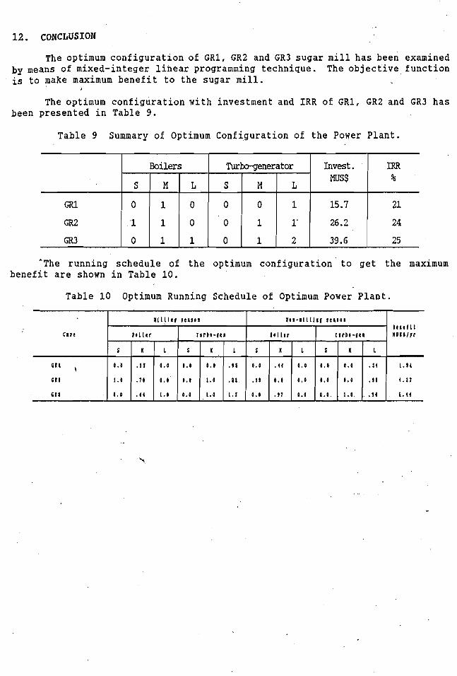
12. CONCLUSION
The optimum configuration of G R 1 , GR2 and GR3 sugar mill has been examined by means of mixed-integer linear programming technique. The objective function is to make maximum benefit to the sugar mill.
I
The optimum configuration with investment and I R R of G R 1 , GR2 and GR3 has Been presented in Table 9.
Table 9 Summary of Optimum configuration of the Power Plant.
*The running schedule of the optimum configuration to get the maximum benefit are shown in Table 10.
Table 10 Optimum Running Schedule of Optimum Power Plant.
IRR %
21
24
25
GR1
GR2
GR3
Cast
E l l , E l l
G I 1
Invest. Muss
15.7
26.2
39.6
Boilers
I t r t f l l n l r r # l r r
1 . 9 1
4 . 1 7
1.(1
S
0
1
0
Turbo-genera tor
I l l l l l f 1 t a : t l
S
0
0
0
1 t 1 - 1 1 1 1 1 1 ( : t a 1 0 1
M
1
1
1
9 t l I t r
L
0
0
1
M
0
1
1
r ~ r b t - ( ( I 9 o l I t r
S
0 . 0
1 . 0
8 . 0
L
1
1.
2
r ~ r b b - g e t
0 . 0
. J 9
0 . 0
.)I
1
1 . 5
. J I
. I 0
4
X L S K L S
0.0
0 . 1
4 . 0
L
. 1 4
. J I
4
4 4
0 . 0
.01
0 . 1
1 . 0
4 . 0
0 . 0
0 . 0
1 . 0
1 . 0
1 . 0
1 . 0
X L S
0 , 0
0 . 0
P.4
K
1 . 0
0 . 0
1.1

REFERENCES
BALAKRISHNAN, S.V., 1986, Energy Analysis of Cogeneration in a Sugar Mill, A Research Study Report, Energy Technology Division, Asiqn Institute of Technology (AIT) , Thailand.
HORII, S. et al., 1987, Optimum Planning of as Turbine Co-generation Plants Based on Mixed-Integer Linear Programming, Inter. J. of Energy Research, V.ll, p.507-518.
KADYSZEWSKI, J., A. PHILLIPS, H. STEINGASS, F. TUGWELL and T. VORFELD. 1989. Trial Year Program Proposal Nong Yai Sugar Mill, Thailand,. Office of Energy, USAID, Washington DC, U.S.A.
LARSON, E.D., J.M. OGDEN, R.H. WILLIAMS. 1987. Steam-injected Gas Turbine Cogeneration for the Cane Sugar Industry: Optimization Through '
Improvements in Sugar Processing Efficiencies (PU/CEES 217). Princeton, New Jersey: Center for Energy and Environment Studies, Princeton University, U.S.A.
RODDEN, R.M. et al., 1986, Reference Guide to Small Cogeneration System for Utilities, EPRI Research Project No. 1276-20, U.S.A.
SPIEWAK, S.A., 1987, Cogeneration and Small Power ,Production Manual. Fairmont Press, U.S.A.
TAMNANTHONG, N., 1986, Thermal Energy Analysis in a Sugar Mil1,A Research Study Report, Energy Technology Division, Asian Institute of Technology (AIT), Bangkok, Thailand.
\
THE SUGAR ENGINEERING DIVISION, 1990, The Machine for Processing Sugar, Office of the Cane Sugar Board, Ministry of Industry, Bangkok, Thailand.
TUGWELL, F., M. GOWAN, W. KENDA and A. COHEN. 1989, Electric Power from Sugarcane in Costa Rica, Office of Energy, USAID, Washington DC, U.S.A.
\