substructuring technique in nonlinear analysis of brick masonry subjected to concentrated load
TRANSCRIPT

Computers 1 S~rur~ures Vol. 27. No. 3. pp. 417425. 1987 0045.7949187 f3.00 + 0.00 Printed I” circa: kitam. Q 1987 Perpmon Journals Ltd.
SUBSTRUCTURING TECHNIQUE IN NONLINEAR ANALYSIS OF BRICK MASONRY SUBJECTED TO
CONCENTRATED LOAD
S. ALL I. D. MOORE and A. W. PAGE
Department of Civil Engineering and Surveying, University of Newcastle, New South Wales 2308, Australia
(Received 5 February 1987)
Abstract-A multi-level substructuring technique and a mesh grading scheme are used in the nonlinear finite element analysis of brick masonry subjected to in-plane concentrated loads. Masonry structures are ideally suited for solution using these techniques since masonry consists of a regular assemblage of bricks and joints in a repetitive pattern. Large wall panels can therefore be modelled without the need for excessive computer storage requirements. It is shown that the dual application of these techniques is highly efficient and leads to significant savings in costs. The possibility of modelling the elastic region of brick masonry as an isotropic continuum using similar techniques is also considered.
INTRODUCTION
Since the introduction of the substructuring tech- nique in the early sixties for the numerical analysis of aerospace structures featuring many degrees of free- dom, a number of refinements and variations of the technique have been reported in the literature [l-3]. The primary concern of these studies has been the reduction of the number of variables that must be retained in the comptuer memory at a given time during the solution process. This permits the analysis of very large structural systems with computers hav- ing small to medium in-core capacity. Another attrac- tive feature of substructuring techniques is that they often lead to significant reductions in overall com- putational effort.
-The efficiency of a finite element analysis will also be improved by refining the finite element mesh where accurate modelling of displacement and stress fields is most important, and by having a coarser discretis- ation elsewhere. A number of investigators have addressed this problem, and efficient mesh-refinement schemes [4,5] have been developed.
The finite element analysis of masonry is formid- able given the composite nature of the material, since masonry consists of brick units set in a mortar matrix, each with differing deformation and strength characteristics. However, a masonry wall is a regular assemblage of these identical structural units, and is therefore an ideal candidate for solution using sub- structuring techniques. For many problems the calcu- lation of brick masonry strength requires an elastic-plastic fracture analysis, so that the use of a mesh refinement scheme is also advantageous when the detailed modelling of brick and joint is necessary for crack propagation analysis.
This paper reports how both substructuring and mesh-refinement techniques have been successfully used in the analysis of masonry walls subjected to
in-plane concentrated loads. In the analysis, the part of the structure which is known (by physical consider- ations or experience) to remain elastic during the deformation process is defined as one substructure and is treated as a collection of elastic bricks and mortar joints. The remainder of the masonry wall which undergoes plastic deformation and fracturing is defined as another substructure. The present model allows for nonlinear material characteristics and progressive local cracking for the inelastic region. The load is applied incrementally so that the response of the wall from first crack through to final failure is determined. The possibility of modelling the elastic region of brick masonry as an isotropic homogeneous material is also considered. Example problems are included to show how the procedure operates and to demonstrate the significant savings which can be achieved through the use of substructuring and mesh- refinement techniques.
NONLINEAR APPLICATIONS IN MASONRY STRUCTURES
Nonlinear analysis has become an important aspect of research into the behaviour of masonry structures, particularly if ultimate loads are to be predicted. Nonlinear behaviour in masonry struc- tures is produced both by the nonlinear deformation characteristics of its component materials (particu- larly the mortar joints), and the progressive local cracking that occurs in both bricks and joints. The bulk of this cracking is a result of the low bond strength that typically exists between the brick-mortar interface. For many cases of in-plane loading, such as walls subjected to concentrated loads, shear walls or frames with masonry infill, failure usually occurs by the formation of a few dominant cracks with very little failure elsewhere.
The computing cost of nonlinear analysis is often
418 S. ALI ei al.
an order of magnitude grcatcr than for a linear analysis of the same structure. Fortunately, nonlinear behaviour usually occurs in isolated regions in many masonry structures, especially for the case of a wall subjected to concentrated loads. Considerable advan- tages can therefore be gained by subdividing the structure into elastic and inelastic regions, and using the substructuring technique to determine the stiffness of the boundary of the elastic region. Addi- tional simplifications can be achieved by modelling the elastic region as an equivalent isotropic homoge- neous material, thus avoiding the need to consider bricks and joints separately.
THE SUBSTRlJClWRING CONCEPT FOR ELASTO-PLASTIC FRACIWRE ANALYSIS
Considering the usual incremental/iterative process for the solution of elasto-plastic fracture problems, the application of the substructuring technique can be summarised as follows.
The relationship between the stiffness matrix K, the incremental nodal forces AP, and the incremental nodal displacements AU, of a structure is given by
KAU = AP. (1)
Equation (1) can be partitioned into elastic and inelastic parts and written in matrix form as
[:; :] [$I = [:;I. @)
where subscripts e and p denote elastic and plastic terms respectively. Equation (2), when expanded, leads to
and
(3)
APp = K,AU, + KppAUp. (4)
Solving eqn (3) for AUc:
ALI, = K,‘(AP, - KcflAUp), (5)
which can be substituted into eqn (4) to yield an expression for AP, in terms of only the degrees of freedom in the plastic region AU,,, viz.:
AP,-K,K,'AP,=(K,,- KwKly'KII))AUp. (6)
Now let
AP:= K,K,'AP, (7)
and
K: = K,K,'K,,; (8)
then cqn (6) can bc rewritten as
rPp = K,AU,. (9)
in which
and
R,= K~~-K:. (11)
The terms AP: and K:, defined in eqns (7) and (8) are respectively the condensed incremental load and the condensed stiffness matrix for the elastic sub- structure. After the problem has been solved for the nodal displacements in the plastic region (AUp) using eqn (9), the nodal displacements in the elastic region (AU,) are obtained by substitution of AL$ into eqn
(5).
USING SUBSTRUCTURES TO MODEL THE ELASTIC REGION OF BRICK MASONRY
Perhaps the most obvious feature of any masonry structure is its composition-it is a multitude of identical structural units joined together in a repeti- tive pattern. It is by definition a natural system of substructures, and the regular nature of its construc- tion means that most masonry structures can be subdivided into units of various scales. This charac- teristic can be used to improve the efficiency of structural modelling considerably by the calculation of the boundary stiffness of the elastic region.
Non-homogeneous model
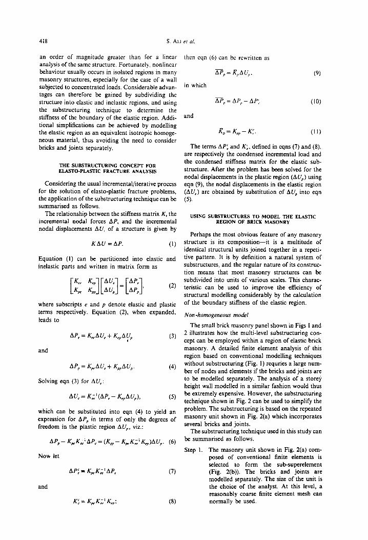
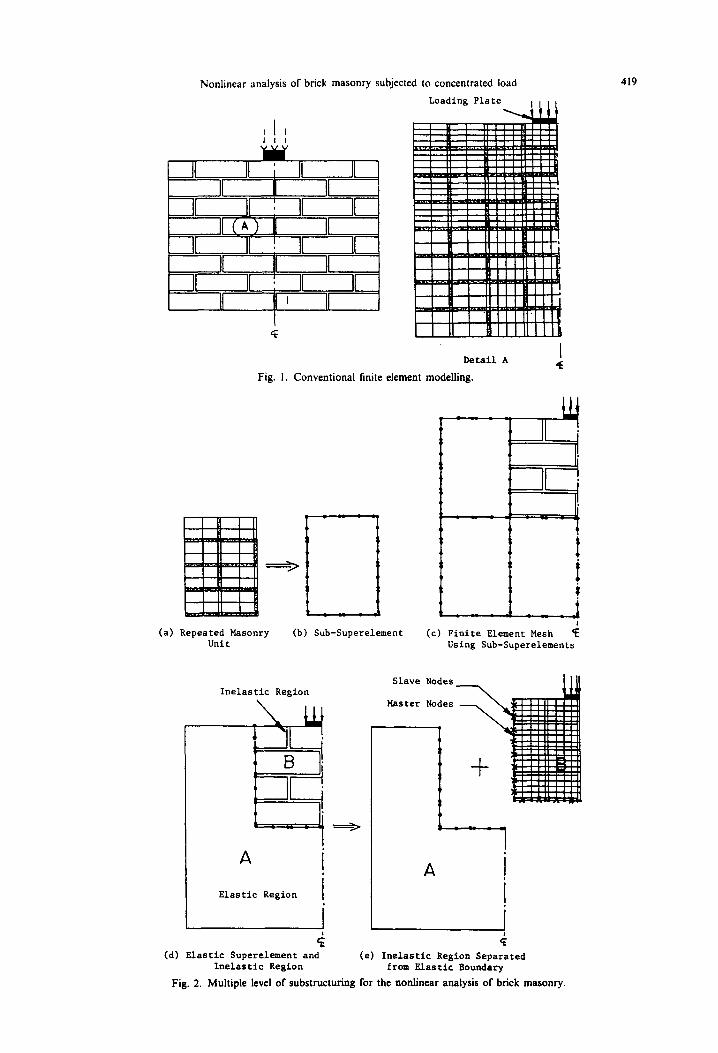
The small brick masonry panel shown in Figs 1 and 2 illustrates how the multi-level substructuring con- cept can be employed within a region of elastic brick masonry. A detailed finite element analysis of this region based on conventional modelling techniques without substructuring (Fig. 1) requries a large num- ber of nodes and elements if the bricks and joints are to be modelled separately. The analysis of a storey height wall modelled in a similar fashion would thus be extremely expensive. However, the substructuring technique shown in Fig. 2 can be used to simplify the problem. The substructuring is based on the repeated masonry unit shown in Fig. 2(a) which incorporates several bricks and joints.
The substructuring technique used in this study can be summarised as follows.
Step 1. The masonry unit shown in Fig. 2(a) com- posed of conventional finite elements is selected to form the sub-superelement (Fig. 2(b)). The bricks and joints are modelled separately. The size of the unit is the choice of the analyst. At this level, a reasonably coarse finite element mesh can normally be used.
Nonlinear analysis of brick masonry subjected to concentrated load 419
I I I
Loading Plate
t i ii i iiiiiiiiil Detail A I
4 Fig. 1. Conventional finite element modelling.
(a) Repeated Masonry Unit
(b) Sub-Superelement (c) Finite Element Mesh < Using Sub-Superelements
Inelastic Region
Elastic Region
i
Slave Nodes
Master Nodes
A ]
!
(d) Elastic Superelement and (e) Inelastic Region Separated Inelastic Region from Elastic Boundary
Fig. 2. Multiple level of substructuring for the nonlinear analysis of brick masonry.

420 S. ALI e/ al.
Step 2. The stiffness of the sub-superelement (Fig. 2(b)) is evaluated using static condens- ation of the internal degrees of freedom. The order of this sub-superelement depends on the size of the unit chosen in step 1.
Step 3. The stiffness of a section of the elastic masonry panel composed of a number of the sub-superelements from step 2 (Fig. 2(c)) is evaluated using conventional assembly methods.
Steps 2 and 3 can be repeated as many times as necessary. For an ‘infinitely’ (or ‘very’) long wall the process can be repeated until interaction between each end of the structure is negligible [6]. This is manifest when terms in the superelement stiffness matrix which relate degrees of freedom at opposite ends of the structure become negligible. Otherwise the process ceases when the whole of the elastic masonry panel has been modelled. For an analysis featuring a section of the structure which responds inelastically (part ‘B’ in Fig. 2(d)), only the elastic stiffness of the boundary (I-2-3) surrounding the inelastic region is required at this level.
A result of the substructuring process as described is that the modelling of the displacements and stress fields is the same as that for a conventional solution based on the smallest element unit. However, huge reductions in the number of equations to be manipu- lated have resulted, leading to significant savings in computation and storage.
Homogeneous isotropic model
For concentrated load problems, where nonlinear behaviour is localised near the loading point, it may be possible to model the region of elastic brick masonry as a homogeneous material (rather than modelling bricks and joints separately). This would enable a coarser mesh to be used for the repeated masonry unit to be condensed as a sub-superelement. The substructuring and mesh-refinement schemes de- scribed above will still be employed and these tech- niques will be advantageous if large areas are to be modelled.
The equivalent homogeneous material properties were calculated by examining the behaviour of small masonry panels under uniform prescribed displace- ment. For the brick/mortar combination considered in this study, the stiffness in directions normal and parallel to the bed joint were found to be similar. This simplified model was also used to analyse the behav- iour of a storey height wall subjected to concentrated load, and the results compared to that obtained from the more refined analysis (modelling elastic region as non-homogeneous material) previously described.
Use of slave nodes to control mesh-refinement
When a masonry wall is subjected to a concen- trated load, very high stresses are developed in the region beneath the loading plate, with the remainder
of the wall being relatively lightly stressed. Conse- quently a fine mesh is required near the load to model the high stress gradients present, with a coarser mesh elsewhere. The use of this fine mesh near the loading point in conjunction with a coarse mesh in the elastic part of the brick masonry can be facilitated by using the mesh-refinement scheme of Gupta [5]. Slave (or dependent) nodes are introduced between master nodes when the transition from one discretisation level to another is required (see Fig. 2(e)). In this study the interface point concept proposed by Anand and Shaw [7] for the constant strain triangular ele- ment has been applied to the linear quadrilateral element.
MODELLINC OF THE INELASTlC REGION
Once the elastic boundary stiffness is known, the inelastic region together with this boundary stiffness can be analysed using the techniques normally re- quired for any nonlinear fracture problems. The analysis of this region requires a representative ma- terial model. Only a brief description of the material model used for this region will be presented in this section, since the model is described in detail else- where [8].
A complete material model requires the definition of constitutive relations before and after failure and a suitable failure criterion. In this study the wall has been assumed to be in a state of plane stress. Previous work has shown that this is a reasonable assumption provided the concentrated load is applied across a significant portion of the wall thickness [9]. Previous elastic analysis has shown that the stress state be- neath the concentrated load is predominantly one of biaxial tension+ompression. The main cause of non- linear behaviour in this case will therefore be progressive local cracking rather than material non- linearity. Hence, relatively simple constitutive re- lations for the material are justified.
In the experimental study which was carried out in parallel with the analytical investigation, all masonry was constructed from solid concrete bricks and a compatible mortar. Tests were performed on both small samples of the masonry and its components as well as on larger wall panels [8, lo].
Deformation characteristics
The deformation characteristics of the bricks were found to be nonlinear in nature. In the analytical formulations, incremental stress-strain relations were used with a tangent modulus of elasticity appropriate to the stress level [8]. Poisson’s ratio was found to be approximately constant up to a stress level corre- sponding to 75% of the brick strength. Since brick stresses rarely reached this level in the analysis, a constant value of 0.16 was adopted.
A relatively simple nonlinear stress-strain formu- lation was adopted for the mortar joints. A model similar to that proposed by Dhanasekar et al. (111
Nonlinear analysis of brick masonry subjected to concentrated load 421
was chosen. The mortar stress-strain curves were (3) Crushing of the brick or mortar under a stress
derived indirectly from prism tests (for normal and state of biaxial compression-compression.
parallel strains), and from brick masonry couplets with sloping bed joints (for shear strains). The tests
To predict joint bond failure (Type (1) above), a
adopted and the derived relationships have been three dimensional failure surface in terms of the
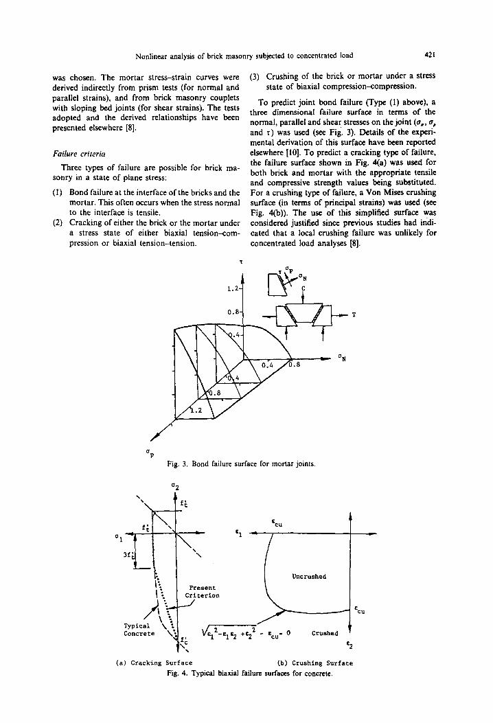
presented elsewhere [8]. normal, parallel and shear stresses on the joint (a,, oP and ‘t) was used (see Fia. 3). Details of the experi- mental derivation bf this-surface have been reported
Failure criteria elsewhere [IO]. To predict a cracking type of failure,
Three types of failure are possible for brick ma- the failure surface shown in Fig. 4(a) was used for
sonry in a state of plane stress: both brick and mortar with the appropriate tensile and compressive strength values being substituted.
(I) Bond failure at the interface of the bricks and the For a crushing type of failure, a Von Mises crushing mortar. This often occurs when the stress normal surface (in terms of principal strains) was used (see
to the interface is tensile. Fig. 4(b)). The use of this simplified surface was (2) Cracking of either the brick or the mortar under considered justified since previous studies had indi-
a stress state of either biaxial tension-com- cated that a local crushing failure was unlikely for pression or biaxial tension-tension. concentrated load analyses (81.
-T
Fig. 3. Bond failure surface for mortar joints.
1::
1 :; Present
Criterlon
-.
f ’ \- \;
Uncrushed
Crushed
(a) Cracking Surface (b) Crushing Surface
Fig. 4. Typical biaxial failure surfaces for concrete.

422 S. ALI
When failure was indicated, the effects of the failure were ‘smeared’ over the full width of the element. The stiffness coefficients appropriate to the failure mode were reduced to their appropriate value, and the problem resolved, to allow stress redis- tribution to occur.
turing region whose height is about one half the height of the wall with the material in the bottom half of the structure being modelled elastically. For this study the depth of the inelastic region was taken to be 60% of the wall height.
The material model described above was originally incorporated into a conventional finite element model without substructuring, and its validity demonstrated by comparing the predicted and observed per- formance of small concrete masonry panels subjected to concentrated loads [8]. The present study focuses on the incorporation of substructuring and mesh- refinement techniques into the finite element model to allow the analysis of more realistic storey height walls subjected to concentrated loads. Examples of the use of these techniques follow.
The assumed width of the inelastic region varies depending on the size of the loading plate. In this study the width of the region was selected in such a way that there was at least one potential vertical plane of weakness outside the edge of the loading plate (the planes of weakness correspond to the lines of the vertical joints).
NUMERICAL EXAMPLES
SELECTION OF THE INELASTIC REGION FOR THE CONCENTRATED LOAD ANALYSES
Earlier investigations [8] indicated that cracks al- ways initiated from the vertical joints some distance away from the loading plate and then propagated towards the loading plate and the base of the wall. During the initial stages, the crack (or cracks) prop- agated as the load was increased, indicating that the crack propagation was stable. The response remained stable until cracks reached a depth of approximately 40-60% of the wall height below the loading plate. After this, further crack propagation was accom- panied by a decrease in the applied load, representing an unstable condition. Both the stable and unstable conditions can be analysed because the load is ap- plied in the form of a prescribed displacement. It is therefore reasonable to specify a plastic and frac-
In order to demonstrate the application and effectiveness of the numerical techniques described, two brick masonry walls were selected for analysis. The first wall was 20 brick courses high and six bricks wide (Fig. 5) and is small enough to permit analysis by the conventional finite element method (without substructuring) for purposes of comparison. The second wall was 24 courses high and 12 bricks wide (see Fig. 7). These dimensions are typical of those of a real wall. Because of the large number of bricks and joints involved, it cannot be readily analysed using the conventional finite element method if the joints and the bricks are to be modelled separately.
er al.
i P ult= 244.5 kN
(b) Mode of Failure
Fig. 5. Conventional nonlinear finite element analysis.
Two solutions were obtained for the first case, one using the conventional finite element procedure and the other using a procedure incorporating the sub- structuring and mesh-refinement techniques. Only half of the wall was analysed because of symmetry. A total of 1672 four-noded quadrilateral elements were used for the conventional solution since a fine mesh was needed near the loading point (see Fig.
(a) Conventional Finite Element Discretisation

Nonlinear analysis or brick masonry subjcctcd to concentrated load 423
5(a)). For the second procedure the same finite element mesh was used in the inelastic region but substructuring and mesh refinement techniques were used in the modelling of the elastic region (see Fig.
6(a)). Load was applied incrementally in the form of
prescribed displacement over 10% of the wall area. The nonlinear analysis was subdivided into 25 load increments, and an average of 12 iterations were needed for each load increment. Before any local failures occurred, the initial stiffness method was found to be the most effective in reproducing material nonlinearities. However, once local failure occurred in the masonry constituents, convergence became very slow using the above method. Hence, after the initiation of the first crack, the solution procedure was changed to modified Newton-Raphson method. Using this method the stiffness matrix was updated at the first iteration for each load increment.
The behaviour of the wall was traced from the linear elastic condition into a plastic state, and even- tually to ultimate failure. The final failure patterns and failure loads are shown in Figs 5(b) and 6(b). Almost identical cracking patterns and ultimate loads were predicted using both analyses, with the ultimate loads differing by only 1.3%. For the conventional solution, the CPU time using a VAX-11/780 com- puter was 3 hr 24 min 27 sec. For the second analysis the CPU time was only 47 min 22 set, less than 25% of the former case. For larger walls the differences would be even more significant, and the benefits to be gained from the use of the techniques described earlier are obvious.
The larger masonry wall was analysed using the
G
substructuring technique for two different loading conditions: a concentric load (Fig. 7(a)), and an edge loading (Fig. 7(b)). Loads were again applied in the form of prescribed displacements with a loaded area equal to 10% of the wall area. Failure patterns and failure loads are shown in Figs 7(a) and 7(b). In both cases the cracks formed in vertical lines correspond- ing with the edge of the loading plate where both shear and normal stresses are quite high. These stresses initiated joint bond failure in vertical mortar joints with subsequent propagation of the crack in a vertical direction through alternate joints and bricks. The ultimate load for the concentric case was consid- erably higher than the corresponding edge loading. This is due to the higher local stresses in the region of the edge of the loading plate for the eccentric case
[91. The concentric loading case shown in Fig. 7(a) was
also analysed using the homogeneous isotropic ma- terial model for the elastic region. The results of the analysis are shown in Fig. 8. It can be seen that the ultimate load and failure pattern are almost identical to those shown in Fig. 7(a) for the substructuring analysis based on explicit brick/joint modelling for the elastic region (the failure loads differed by only 1.14%). It is clear that for this particular problem it is quite reasonable to use the homogeneous isotropic material model for the elastic region. This then provides an even more efficient procedure for calcu- lating the stiffness of the elastic boundary, since a coarser mesh can be employed. More work is needed to more generally identify the circumstances under which the homogenous mode1 can be expected to yield satisfactory results.
P ,,,*- 247.6 kN
Inelastic Region --, , , , ,
Elastic Region
(a) Finite Element Discretisation Using Substructuring
Technique
(b) Mode of Failure
Fig. 6. Nonlinear finite element analysis using substructuring technique.

424 S. ALI cl al.
(a) Failure Pattern for Concentric Concentrated Load
351.6 kN
(b) Failure Pattern for Eccentric Concentrated Load
Fig. 7. Nonlinear finite element analysis of storey height walls subjected to concentrated loads
CONCLUSIONS
The substructuring technique in conjunction with a rn~h-refinement scheme has been successfully used for the nonlinear fracture analysis of brick masonry subjected to a concentrated load. The combined use of substructuring and mesh-refinement schemes per- mits the analyst to select an extremely small element site in regions of high stress gradients, and a much coarser mesh elsewhere, thus achieving a balance between realistic modelling of the actual behaviour and computational effort. For the concentrated load problem, where nonlinea~ty primarily occurs in the vicinity of the loading point, substructuring and
mesh-refinement schemes with condensation dras- tically reduce the number of nodes involved in the nonlinear solution, and ultimately save from 60 to 80% of CPU time. Because of this significant saving, the behaviour of full wah panels subjected to concen- trated loads can be studied.
The separation of the inelastic region from the elastic region for the brick masonry enables the analyst to diyretise both regions inde~ndently, thus also simplifying data preparation. In general, elastic substructures should be modelled by considering bricks and joints separately, each with differing prop- erties. However, for the analysis of walls subjected to concentrated loads, it appears that the elastic region

Nonlinear analysis of brick masonry subjected to concentrated load
457.2 k8
Fig. 8. Nonlinear finite element analysis using homogeneous isotropic model for the elastic region.
425
can be modelled as an isotropic, homogeneous mate- rial, thus leading to further efficiencies.
Acknowledgem~~nrs-This work has been carried out in the Department of Civil Engineering and Surveying, The Uni- versity of Newcastle. Part of the work has been funded by the Australian Research Grants Scheme. Bricks were do- nated by the Concrete Masonry Association of Australia.
REFERENCES
I. A. K. Noor, A. H. Kamel and R. F. Fulton, Substructuring techniques-status and projections. Compur. Swucr. 8, 621-632 (1978).
2. C. S. Gurujee and V. L. Deshpande, An improved method of substructure analysis. Compuf. Sfruct. 8, 147-152 (1978).
3. R. H. Dodds, Jr and L. A. Lopez, Substructuring in linear and nonlinear analysis. Inr. J. Numer. Mesh. Engng 15, 583-597 (1980).
4. G. F. Carey, A mesh-refinement scheme for finite
5.
6.
.7.
8.
9.
IO.
I I.
element computations. Compul. Merh. appl. Mech. Engng 7, 93-105 (1976). A. K. Gupta, A finite element for transition from a fine mesh to a coarse mesh. Int. J. Numer. Meth. Engng 12, 35-45 (1978). J. R. Booker and J. C. Small, Finite element analysis of problems with infinitely distant boundaries. Inr. J. Numer. Anaiyt. Merh. Geomech. 5, 345-368 (1981). S. C. Anand and R. H. Shaw, Mesh-refinement and substructuring technique in elastic-plastic finite element analysis. Compur. Struct. 11, 13-21 (1980). S. Ali, A. W. Page and P. W. Kleeman, Nonlinear finite element model for concrete masonry with particular reference to concentrated loads. Proc. 4th Can. Mar. Symp. I, pp. 137-148 (1986). S. Ali and A. W. Page, An elastic analysis of concen- trated loads on brickwork. Mas. Inrl 6, 9-21 (1985). S. Ali and A. W. Page, A failure criterion for mortar joints in brickwork subjected to combined shear and tension. Mar. Inrl 9, 43-54 (1986). M. Dhanasekar, P. W. Kleeman and A. W. Page, Biaxial stress-strain relations for brick masonry. J. Slrucf. Diu., ASCE 111, 1085-1100 (1985).