subsonic airfoils - virginia techmason/mason_f/subsonicairfoilspres.pdfcp x/c xfoil’s inviscid...
TRANSCRIPT

Subsonic AirfoilsW.H. Mason
Configuration Aerodynamics Class
Most people don’t realize that mankind can be divided into two great classes: those who take airfoil selection seriously, and those who don’t.
Peter Garrison, Flying, Sept. 2002

Typical Subsonic Methods: Panel Methods• For subsonic inviscid flow, the flowfield can be found by
solving an integral equation for the potential on the surface• This is done assuming a distribution of singularities along
the surface, and finding the “strengths” of the singularities• The airfoil is represented by a series of (typically) straight
line segments between “nodes”, and the nonpenetration boundary condition is typically satisfied at control points
• Some version of a Kutta condition is required to close the system of equations.
1234
N + 1N
N - 1node
panel
See my Applied Computation Aero page for the derivation

Comparison of Panel Method Pressure Distribution with Exact Conformal Transformation Results
-2.50
-2.00
-1.50
-1.00
-0.50
0.00
0.50
1.00-0.2 0.0 0.2 0.4 0.6 0.8 1.0 1.2
PANELExact Conformal Mapping
Cp
x/cXFOIL’s inviscid calculations use a panel method
The conformal mapping solution is from Antony Jameson

Convergence with increasing numbers of panels
0.950
0.955
0.960
0.965
0.970
0.975
0.980
0 20 40 60 80 100 120
CL
No. of Panels
NACA 0012 Airfoil, α = 8°

How to examine convergence: Lift
0.9500.9550.9600.9650.9700.9750.980
0 0.01 0.02 0.03 0.04 0.05 0.06
CL
1/n
NACA 0012 Airfoil, α = 8°

Convergence with Panels: Moment
-0.250
-0.248
-0.246
-0.244
-0.242
-0.240
0 0.01 0.02 0.03 0.04 0.05 0.06
Cm
1/n
NACA 0012 Airfoil, α = 8°

Convergence with Panels: Drag
0.0000.0020.0040.0060.0080.0100.012
0 0.01 0.02 0.03 0.04 0.05 0.06
CD
1/n
NACA 0012 Airfoil, α = 8°

Pressures: 20 and 60 panels-5.00
-4.00
-3.00
-2.00
-1.00
0.00
1.000.0 0.2 0.4 0.6 0.8 1.0
20 panels60 panels
CP
x/c
NACA 0012 airfoil, α = 8°

Pressures: 60 and 100 panels-5.00
-4.00
-3.00
-2.00
-1.00
0.00
1.000.0 0.2 0.4 0.6 0.8 1.0
60 panels100 panels
CP
x/c
NACA 0012 airfoil, α = 8°

Comparison with WT Data: Lift- recall: panel methods are inviscid! -
-0.50
0.00
0.50
1.00
1.50
2.00
2.50
-5.0° 0.0° 5.0° 10.0° 15.0° 20.0° 25.0°
CL, NACA 0012 - PANEL
CL, NACA 0012 - exp. data
CL, NACA 4412 - PANEL
CL, NACA 4412 - exp. data
CL
α
NACA 0012
NACA 4412

Comparison with Data: Pitching Moment- about the quarter chord -
-0.30
-0.25
-0.20
-0.15
-0.10
-0.05
-0.00
0.05
0.10
-5.0 0.0 5.0 10.0 15.0 20.0 25.0
Cm, NACA 0012 - PANELCm, NACA 4412 - PANELCm, NACA 0012 - exp. dataCm, NACA 4412 - exp. data
Cm
α
c/4
NACA 0012
NACA 4412

For Completeness: Drag DataEffect of Camber
-0.50
0.00
0.50
1.00
1.50
2.00
0.004 0.006 0.008 0.010 0.012 0.014 0.016 0.018
CL
CD
Re = 6 million
NACA 4412
NACA 0012
data from Abbott and von Doehhoff

A Sidebar: Can you use thin airfoil theory? Camber Effects: compared to WT Data
-5.00
-4.00
-3.00
-2.00
-1.00
0.00
1.00
-1.0 0.0 1.0 2.0 3.0 4.0 5.0
Camber effect on Alpha Zero Lift
Alphazero lift
percent camber
Thin AirfoilTheory
WT Data
NACA 4 digit series airfoils-0.120
-0.100
-0.080
-0.060
-0.040
-0.020
0.000
0.020
-1.0 0.0 1.0 2.0 3.0 4.0 5.0
Camber effect on Cm0
Cm0
percent camber
Thin AirfoilTheory
WT Data
NACA 4 digit series airfoils
WT Data From Hemke, Elementary Applied Aerodynamics Thin airfoil theory from Houghton and Carpenter, pg 252

WT Data used in
Comparison
From Hemke, Elementary Applied Aerodynamics

Redo our previous comparisons How Well Does Linear Theory Work?
Pretty Well!
-0.50
0.00
0.50
1.00
1.50
2.00
2.50
3.00
-5.0 0.0 5.0 10.0 15.0 20.0 25.0
CL, NACA 0012 - PANELCL, NACA 4412 - PANELCL, NACA 4412 - exp. data CL, NACA 0012 - exp. dataCL 4412 LTCL 0012 LT
CL
α

And the Pitching Moment
-0.14
-0.12
-0.10
-0.08
-0.06
-0.04
-0.02
0.00
0.02
-5.0 0.0 5.0 10.0 15.0 20.0 25.0
Cm, NACA 0012 - PANELCm, NACA 4412 - PANELCm (NACA 0012)Cm (NACA 4412)Cm 4412 LTICm 0012 LT
Cm
α
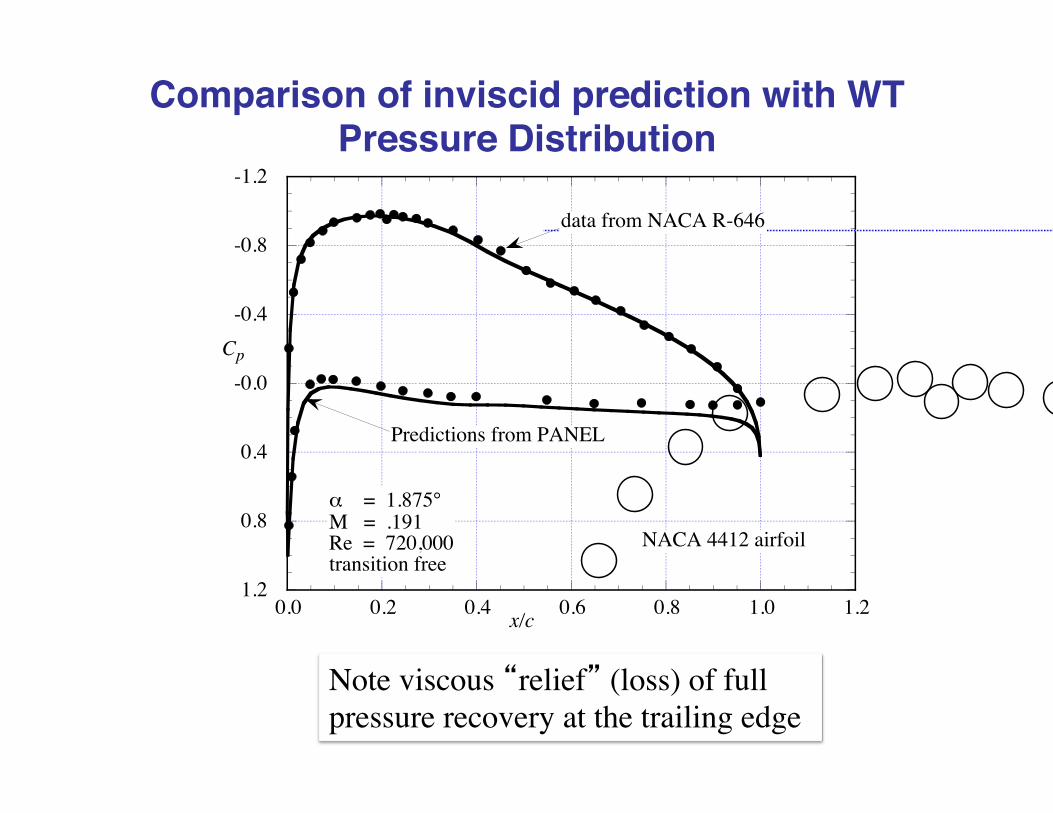
Comparison of inviscid prediction with WT Pressure Distribution
-1.2
-0.8
-0.4
-0.0
0.4
0.8
1.20.0 0.2 0.4 0.6 0.8 1.0 1.2
α = 1.875°M = .191Re = 720,000transition free
Cp
x/c
NACA 4412 airfoil
Predictions from PANEL
data from NACA R-646
Note viscous “relief” (loss) of full pressure recovery at the trailing edge

XFOIL: the code for subsonic airfoils
• Panel Methods: Inviscid!• Couple with a BL analysis to include
viscous effects• The single element viscous subsonic airfoil
analysis method of choice: XFOIL– by Prof. Mark Drela at MIT
• XFOIL also has a “inverse” option• Link available from my software site

Airfoil pressures: What to look for-2.00
-1.50
-1.00
-0.50
0.00
0.50
1.00-0.1 0.1 0.3 0.5 0.7 0.9 1.1
CP
x/c
NACA 0012 airfoil, α = 4°
Trailing edge pressure recovery
Expansion/recovery around leading edge(minimum pressure or max velocity, first appearance of sonic flow)
upper surface pressure recovery(adverse pressure gradient)
lower surface
Leading edge stagnation point
Rapidly accelerating flow,favorable pressure gradient

Effect of Angle of Attack-5.00
-4.00
-3.00
-2.00
-1.00
0.00
1.00-0.1 0.1 0.3 0.5 0.7 0.9 1.1
α = 0°
α = 4
α = 8CP
x/c
NACA 0012 airfoilInviscid calculation from PANEL

Thickness EffectsComparison of NACA 4-Digit Airfoils
0006, 0012, 0018 -0.30
-0.20
-0.10
-0.00
0.10
0.20
0.30-0.1 0.1 0.3 0.5 0.7 0.9 1.1
NACA 0006 (max t/c = 6%)NACA 0012 (max t/c = 12%)NACA 0018 (max t/c = 18%)
y/c
x/c
4-digit series fixes LE radius in relation to t/cmax,Modified 4-Digit allow you to control separately

Thickness Effects on Airfoil PressuresZero Lift Case
-1.00
-0.50
0.00
0.50
1.00-0.1 0.1 0.3 0.5 0.7 0.9 1.1
NACA 0006, α = 0°NACA 0012, α = 0°NACA 0018, α = 0°
CP
x/c
Inviscid calculation from PANEL

Thickness Effects on Airfoil Pressures, CL = 0.48-3.00
-2.50
-2.00
-1.50
-1.00
-0.50
0.00
0.50
1.00-0.1 0.1 0.3 0.5 0.7 0.9 1.1
NACA 0006, α = 4°
NACA 0012, α = 4°
NACA 0018, α = 4°
CP
x/c
Inviscid calculation from PANEL
Small LE Radius leads to high acceleration around the LE

Camber EffectsComparison of NACA 4-Digit Airfoils
the 0012 and 4412
-0.30
-0.20
-0.10
-0.00
0.10
0.20
0.30
-0.1 0.1 0.3 0.5 0.7 0.9 1.1
NACA 0012 (max t/c = 12%)NACA 4412 foil (max t/c = 12%)
y/c
x/c

Highly Cambered Airfoil Pressure Distribution- NACA 4412 -
-2.00
-1.50
-1.00
-0.50
0.00
0.50
1.00-0.1 0.1 0.3 0.5 0.7 0.9 1.1
NACA 4412, α = 0°NACA 4412, α = 4°
CP
x/c
Note: For a comparison of cambered and uncambered presuure distributions at the same lift, see Fig. 18.
Inviscid calculation from PANEL

Camber Effects on Airfoil Pressures, CL = 0.48-2.00
-1.50
-1.00
-0.50
0.00
0.50
1.00-0.1 0.1 0.3 0.5 0.7 0.9 1.1
NACA 0012, α = 4°
NACA 4412, α = 0°
CP
x/c
Inviscid calculation from PANEL

Camber Effects on Airfoil Pressures, CL = 0.96-4.00
-3.00
-2.00
-1.00
0.00
1.00-0.1 0.1 0.3 0.5 0.7 0.9 1.1
NACA 0012, α = 8°NACA 4412, α = 4°
CP
x/c
Inviscid calculations from PANEL

Camber Effects on Airfoil Pressures, CL = 1.43-6.00
-5.00
-4.00
-3.00
-2.00
-1.00
0.00
1.00-0.1 0.1 0.3 0.5 0.7 0.9 1.1
NACA 0012, α = 12°NACA 4412, α = 8°
CP
x/c
Inviscid calculations from PANEL

For Completeness: Drag DataEffect of Camber
-0.50
0.00
0.50
1.00
1.50
2.00
0.004 0.006 0.008 0.010 0.012 0.014 0.016 0.018
CL
CD
Re = 6 million
NACA 4412
NACA 0012
data from Abbott and von Doehhoff

NACA 6712 Airfoil- Heavy Aft Camber Geometry -
-0.05
0.05
0.15
-0.1 0.1 0.3 0.5 0.7 0.9 1.1
y/c
x/c

NACA 6712 Airfoil- Heavy Aft Camber, Pressure Distribution -
-2.00
-1.50
-1.00
-0.50
0.00
0.50
1.00-0.1 0.1 0.3 0.5 0.7 0.9 1.1
α = -.6 (CL = 1.0)
CP
x/c
NACA 6712
Inviscid calculations from PANEL

Whitcomb GA(W)-1 Airfoil
-0.10-0.050.000.050.100.15
0.0 0.2 0.4 0.6 0.8 1.0
y/c
x/c-1.00
-0.50
0.00
0.50
1.000.0 0.2 0.4 0.6 0.8 1.0
Cp
x/c
GA(W)-1
α = 0°
Inviscid calculations from PANEL
Note nearly parallel upper and lower surfaces at the trailing edge

Another Goal for Aerodynamics: Laminar Flow
For many years aerodynamicists have looked for ways to reduce skin friction drag by achieving laminar flow.
One good survey,“Overview of Laminar Flow Control,” by Ron Joslin, NASA/TP-1998-208705Oct. 1998
From Astronautics and Aeronautics. July, 1966

Werner Pfenninger: Active laminar flow X-plane
Courtesy Tony Landis, personal collection
Northrop X-21: April 1963 - 1968
Active Laminar Flow Control via wing slots Major re-work of Douglas WB-66D AR = 7, LE Sweep = 30° t/c = 0.10 Ultimately successful. M = 0.745, Flights 120 and 121

For Airfoils: NLF (Natural Laminar Flow)Maintain a favorable pressure gradient for as long as possible, and then provide a pressure recovery as illustrated below.

Liebeck’s Hi-Lift Airfoil: Geometry and Lift- note shape of pressure recovery -
From R.T. Jones, Wing Theory

Liebeck’s Hi-Lift Airfoil: Drag
From Bertin,Aerodynamics for Engineers

Camberline Design: DesCam
0.00
0.02
0.04
0.06
0.08
0.10
0.12
-0.50
0.00
0.50
1.00
1.50
2.00
0.0 0.2 0.4 0.6 0.8 1.0
(Z-Z0)/C - DesCamZ/C - from Abbott & vonDoenhoff
Z/CΔCP
X/C
Design ChordLoading

Current Trend: “Morphing”Also called “adaptive” or “intelligent”
Airfoil changes shape with flight condition
• Fighters have had scheduled LE and TE device deflections- since the 1970s (F-16 and F-18)
• Today transports are looking to “tweak” surfaces• Example: the X-29 “Discrete Variable Camber”
AIAA 1983-1834, Mike Moore and Doug Frei

Effect on Lift and Drag
AIAA 1983-1834, Mike Moore and Doug Frei
Note: Variable camber changes the lift curve slope
Results in an optimum envelope polar

Airfoil Selection
Issues:• Cruise CL, and CLmax, don’t forget Cm0
- large LE radius?- Near parallel trailing edge closure
• Profile Drag: Laminar flow? – Tailor pressure distribution
• Thickness for low weight and internal volume• Tails: often symmetric, 6 series foils pickedStudy Abbott and von Doenhoff (both) as a start

To Conclude
You have the tools to do single element airfoil design