subsea processing system advisory · 2019-11-12 · figure 1.2 illustrates an example topside...
TRANSCRIPT

ABS | SUBSEA PROCESSING SYSTEMS ADVISORY 2018 | i
SUBSEA PROCESSING SYSTEM ADVISORYAUGUST 2018
© ABS

SECTION 1 – SUBSEA PROCESSING SYSTEM OVERVIEW .................................................................................................................................................................1Introduction ............................................................................................................................................................................................................................................................................................1Benefits and Evolution ...............................................................................................................................................................................................................................................................1Key Technology Challenges ................................................................................................................................................................................................................................................4
SECTION 2 – DEVELOPING THE SUBSEA PROCESSING SYSTEM .........................................................................................................................................6Feasibility Assessment and Conceptual Design .........................................................................................................................................................................................6System Design Basis .....................................................................................................................................................................................................................................................................6System Architecture Development Process ....................................................................................................................................................................................................7Key Design Considerations ..................................................................................................................................................................................................................................................8Design Philosophy ..........................................................................................................................................................................................................................................................................8
SECTION 3 – SUBSEA SEPARATION AND TREATMENT SYSTEM ..........................................................................................................................................11Overview ...................................................................................................................................................................................................................................................................................................11Gravity Separators .........................................................................................................................................................................................................................................................................13Centrifugal Separators ............................................................................................................................................................................................................................................................14Other Separation and Treatment Technologies .......................................................................................................................................................................................15Design ..........................................................................................................................................................................................................................................................................................................15
SECTION 4 – SUBSEA BOOSTING SYSTEM ........................................................................................................................................................................................................16Overview ..................................................................................................................................................................................................................................................................................................16Centrifugal Booster .....................................................................................................................................................................................................................................................................17Helico-Axial Booster ..................................................................................................................................................................................................................................................................18Design ..........................................................................................................................................................................................................................................................................................................18
SECTION 5 – SUBSEA POWER TRANSMISSION AND DISTRIBUTION SYSTEM ..............................................................................................20Overview ................................................................................................................................................................................................................................................................................................ 20Subsea Transformer ....................................................................................................................................................................................................................................................................21Subsea Switchgear ........................................................................................................................................................................................................................................................................21Subsea Variable Speed/Frequency Drive (VSD/VFD) .........................................................................................................................................................................22Subsea UPSs.........................................................................................................................................................................................................................................................................................23Power Connectors and Penetrators ........................................................................................................................................................................................................................23Subsea Power Cable ...................................................................................................................................................................................................................................................................23Design .........................................................................................................................................................................................................................................................................................................24
SECTION 6 – SUBSEA CONTROL AND MONITORING SYSTEM .................................................................................................................................................25Overview .................................................................................................................................................................................................................................................................................................25Produced Water Instrumentation ...........................................................................................................................................................................................................................25Wireless Communication Methods .......................................................................................................................................................................................................................26
SECTION 7 – ABS ROLE .............................................................................................................................................................................................................................................................. 28
SECTION 8 – SUMMARY ..............................................................................................................................................................................................................................................................29
APPENDIX A – ABBREVIATIONS ....................................................................................................................................................................................................................................30
APPENDIX B – REFERENCES .................................................................................................................................................................................................................................................33
APPENDIX C – REGULATIONS ............................................................................................................................................................................................................................................35Regulations for Subsea Processing Systems ...............................................................................................................................................................................................35Regulation/Agreement on Offshore Effluent Discharge ............................................................................................................................................................35
——TABLE OF CONTENTS
Disclaimer:
While ABS uses reasonable efforts to accurately describe and update the information in this Advisory, ABS makes no warranties or representations as to its accuracy, currency or completeness. ABS assumes no liability or responsibility for any errors or omissions in the content of this Advisory. To the extent permitted by applicable law, everything in this Advisory is provided “as is” without warranty of any kind, either expressed or implied, including, but not limited to, the implied warranties of merchantability, fitness for a particular purpose, or noninfringement. In no event will ABS be liable for any damages whatsoever, including special, indirect, consequential or incidental damages or damages for loss of profits, revenue or use, whether brought in contract or tort, arising out of or connected with this Advisory or the use or reliance upon any of the content or any information contained herein.
ACKNOWLEDGMENTWe would like to thank INTECSEA, part of the WorleyParsons Group, for their support and input during the development of this advisory. INTECSEA, through its various initiatives and capabilities, including subsea processing system concept selection and optimization, have assisted the offshore industry to move to subsea system configurations that are now more modular and allow greater flexibility with reduced risk.

ABS | SUBSEA PROCESSING SYSTEMS ADVISORY 2018 | 1
——SECTION 1 – SUBSEA PROCESSING SYSTEM OVERVIEW
INTRODUCTION
Subsea processing requires installing a processing facility on the seabed, which provides a variety of benefits for hydrocarbon production. The building blocks of a subsea processing system (SPRS) comprise the subsea separation/treatment system, subsea boosting system, subsea (re-)injection system, subsea power transmission and distribution system, and subsea monitoring and control system. Typically, an SPRS will at a minimum include a subsea boosting system and/or separation/treatment system. Figure 1.1 shows the layout of an example SPRS.
With advances in new subsea boosting technologies and the maturity of existing technologies, subsea boosting is increasingly being considered as a cost-effective solution for both brownfield and greenfield applications. As the industry adopts subsea boosting and other enabling subsea processing technologies, it is important to review and understand where we are with respect to these technologies. This Advisory provides an overview of the SPRS and associated sub-systems currently available (as of date of publication), and addresses the current technology maturity level, challenges and future trends.
Section 1 provides an overview of SPRS. Section 2 introduces the key steps required for developing an SPRS for a project. Subsea separation, treatment, boosting, and power supply systems are discussed in Sections 3 through 5. Section 6 introduces control and monitoring systems. Section 7 describes the ABS role in the subsea sector along with the associated services offered. Finally, Section 8 provides a summary of the subsea processing system advisory.
Figure 1.1: Example of SPRS Layout
© ABS

2 | SUBSEA PROCESSING SYSTEMS ADVISORY 2018 | ABS
BENEFITS AND EVOLUTION
The development of SPRS and related technologies has evolved from the conventional topside processing regime, driven by the following benefits:• Reduction of capital expense (CAPEX) and operating expense (OPEX) associated with topside facility• Increase in design flexibility• Improvement of recovery and production rates• Extension of field life by boosting• Reduction of flow assurance problems• Debottlenecking topside water treatment constraint• Reduction of energy consumption for produced water• Enabling of deepwater and/or long distance tie-back• Minimization of manual-operation associated with topside facility
Handling and disposal of produced water and solids is a major consideration in the development phase of an SPRS. Typically, when a topside facility is involved, produced water is processed and discharged overboard. In an SPRS, the two primary options are lifting the water to the surface via boosting or disposal via subsea re-injection. Subsea disposal (to the environment) is theoretically possible, but there are major hurdles both from a technical and regulatory standpoint. Sand and other solids, such as scale are typically handled on the topsides via mechanical clean out and disposal. This also presents major challenges for an SPRS.
Figure 1.2 illustrates an example topside processing system and the current technologies that have been successfully marinized for subsea use (depicted within the dashed line) as of date of publication. Primary separation and with solids and water treatment systems are currently available. Gas processing and oil treatment technologies are yet to be developed, and require additional advanced treatment to be conducted either on topside or onshore before the product can be delivered to the consumers.
The first commercial SPRS project using a separator was Equinor’s (formally Statoil) Troll C, which was installed in 1999 and started production in 2001. At that time, the production of gas from the Troll C reservoir was facing a water cut (the ratio of water produced compared to the volume of total liquids produced) of up to 90% in the production stream. To enhance oil recovery, a Subsea Separation and Injection System (SUBSIS) was developed, using a horizontal gravity separator and a re-injection pump to separate bulk water from the hydrocarbon stream and then re-inject it into the low-pressure aquifer. Troll C was the first successful application for brownfield projects – improving recovery and boosting production. Since then several subsea separation systems using different technologies have been developed to address specific field development needs. Table 1.1 lists the subsea separation systems commissioned as of date of publication with their critical characteristics.
Figure 1.2: Current Technology Status of Marinization of SPRS Technologies (As of Date of Publication)
© ABS

ABS | SUBSEA PROCESSING SYSTEMS ADVISORY 2018 | 3
Table 1.1: Summary of Subsea Separation Projects
Year to launch 2001 2004 2007 2009
Project name Troll-C Pilot Marimba Tordis Parque Das Conchas (BC-10)
Major operator Statoil Petrobras Statoil Shell
Location Norwegian Sea Brazil Offshore Norwegian Sea Brazil Offshore
Separation system SUBSIS VASPS SSBI Caisson Separation
Technology Horizontal gravity with cyclonic inlet Caisson with ESP
Semi-compact horizontal gravity with cyclonic inlet
Caisson with ESP
Purpose Liquid/Liquid Gas/Liquid Gas/Oil/Water/Sand Gas/Liquid
Manufacturer ABB, Norsk Hydro FMC FMC FMC
Water depth, m 340 395 210 1800
Tie-back distance, km 3.3 1.7 12 25
Separator diameter, m 2.8 0.66 2.1 1
Separator length, m 9 72 17 100
Produced water export Injected to low pressure aquifer
Routed with oil to topside
Injected to disposal reservoir
Routed with oil to topside
Design PRWI OiW, ppm 1000 Not applicable 1000 Not applicable
Sand handling Sand flushing system Use ESP, performing stop-start to flush sand
Sand jetting system, desander
Use ESP, performing stop-start to flush sand
Sand export Routed with injected produced water
Routed with liquid to topside
Initially to reservoir, then routed with liquid to topside
Routed with liquid to topside
Status Active Inactive, well failure Active Active
Year to launch 2010 2011 2011 2015
Project name Perdido Marlim Pazflor Asgard
Major operator Shell Petrobras Total Statoil
Location U.S. GoM Norwegian Sea Angola Offshore Norwegian Sea
Separation system GLCC SSAO Hybrid Scrubber
Technology Caisson with ESP Pipe separator and hydrocyclone
Veritcal gravity and cyclonic separator
Compact vertical vessel with inlet swirl
Purpose Gas/Liquid Gas/Oil/Water/Sand Gas/Liquid Condensate/Gas
Manufacturer FMC FMC FMC Aker Solutions
Water depth, m 2500 870 800 300
Tie-back distance, km 0 3.8 4 40-50
Separator diameter, m 0.9 Not available 3.5 approx. 3
Separator length, m 107 60 9 approx. 8
Produced water export Routed with oil to topside
Reinjected to production reservoir
Routed with oil to topside Not applicable
Design PRWI OiW, ppm Not applicable 100 Not applicable Not applicable
Sand handling Use ESP, performing stop-start to flush sand
Inline desander; dual sand jetting system Sand flushing system Not applicable
Sand export Route with liquid to topside
Routed with the oil to topside
Routed with liquid to topside Not applicable
Status Active Active Active Active
SUBSIS: subsea separation and injection systemVASPS: vertical annular separation and pumping systemSSBI: subsea separation, boosting and injectionGLCC: gas-liquid cylindrical cyclonic systemSSAO: equivalent to subsea oil-water separation in English

4 | SUBSEA PROCESSING SYSTEMS ADVISORY 2018 | ABS
Subsea pumps have been used in approximately 40 fields for well stream transportation and produced water reinjection since 1994. Subsea pumps are now considered a field-proven technology able to pump both multi-phase and single-phase flow. Centrifugal, helico-axial, and electrical submersible pumps (ESP) are the prevailing types, while twin-screw pumps are less common. Due to the benefits and reliability of subsea pumps, they are increasingly being considered as a solution for secondary recovery and enhanced oil recovery (EOR). Figure 1.3 illustrates subsea boosting installations associated with deployed water depth.
Figure 1.3: Subsea Boosting Installation
The first application of a subsea gas compressor happened much later compared to other subsea processing equipment. It was only in 2015 that the first subsea compressor was installed and operated. At the time of publication, only two projects have utilized this technology, using centrifugal compressors for dry gas and helico-axial compressors for wet gas.
Offshore Magazine annually publishes the Worldwide Survey Of Subsea Processing poster that lists all the existing subsea processing projects. Given the operational history, proposed projects and increased acceptance by Operators as a field development solution, subsea processing technologies are anticipated to be mature in the near future and lead to more efficient developments. The industry is progressing towards a complete standalone subsea production solution, often referred to as a “Subsea Factory”.
KEY TECHNOLOGY CHALLENGES
SUBSEA PRESSURE VESSELS DESIGN IN DEEP WATER APPLICATION Subsea pressure vessels such as gravity separators with large diameter have been used in shallow water where there is limited effects from external hydrostatic pressure. However, increased water depth and external pressure reduces their feasibility in deep water because thick wall designs are typically required which make such pressure vessels difficult and expensive to manufacture and install. Similar concerns also apply to other types of pressure vessel equipment, such as subsea transformers, variable speed drives (VSDs), and switchgears. One possible solution is the adoption of a pressure compensation-based design that balances the pressure differential. Several manufacturers are working towards this solution.
© ABS

ABS | SUBSEA PROCESSING SYSTEMS ADVISORY 2018 | 5
LONG DISTANCE POWER TRANSMISSION AND DISTRIBUTIONAs many targeted fields have extremely long tie-backs, they require increased power for operation and accordingly more efficient power supply solutions are needed. Subsea switchgears, distributors, VSDs, and uninterrupted power systems (UPSs) are emerging technologies aimed at remediating those issues with respect to current spike and damaging harmonics due to the long tie-backs. This concept is undergoing verification and validation processes by power solution vendors. See Section 4 for more details.
The use of high voltage power lines in a subsea application increases the potential for failure modes of the power cable, such as alternating current corrosion, and can result in down time. The reliability issues have the potential to limit the economic viability.
MONITORING AND CONTROL CHALLENGESWith the increased complexity and additional equipment located on the seafloor, the requirements for subsea monitoring and control systems have become more demanding. This includes bandwidth increase, real-time monitoring, prompt control response, processing equipment automation, and safety system/equipment design.
Subsea sensor technology associated with the measurement of produced water quality is relatively new and critical. Currently, light scattering is the only technology being used, but other sensor technologies are being developed.
VERIFICATION AND VALIDATION STRATEGY FOR NEW TECHNOLOGYThe effort and expense associated with developing a new SPRS technology is still quite high. It requires long term and complex qualification programs to demonstrate the technology readiness levels (TRLs) of both components and the system overall. The selected verification and validation strategy can affect projects with respect to both cost and schedule. Standardizing and optimizing technology qualification programs may improve cost effectiveness.

6 | SUBSEA PROCESSING SYSTEMS ADVISORY 2018 | ABS
——SECTION 2 – DEVELOPING THE SUBSEA PROCESSING SYSTEM
FEASIBILITY ASSESSMENT AND CONCEPTUAL DESIGN
One of the initial phases of field development planning involves an assessment to determine the optimal technical solutions for the field including feasibility of implementing subsea processing for the specific project. The objective of this phase is to define project requirements and evaluate technical feasibility and project economics based on a conceptual system architecture. Tasks associated with performing this assessment include but are not limited to:
• Development of conceptual block flow diagram (BFD) and process flow diagram (PFD) as relevant
• Evaluation of risks involved with economic, legal, environmental, and operational conditions
• Performance of high level flow assurance analysis
• Completion of preliminary risk assessments
• Estimation of CAPEX/OPEX, schedule, and profit
Once these tasks have been performed, the process can move to the more detailed front-end engineering design (FEED) process, where a design basis is established and system architecture is developed. These activities are iterative in nature and continues until the appropriate project requirements and optimal SPRS system architecture design are determined.
SYSTEM DESIGN BASIS
Design basis and/or functional specifications provide the fundamental data on how the subsea processing system and components are to be configured for the project needs. It should clearly define the desired level of compliance and contain no contradictory requirements between the different hierarchies. It is important to focus on variables outside of the project’s control such as well pressure and effluent properties at this stage. Key elements of a design basis include, but are not limited to:
• Project requirements
• Process, operating and environmental parameters
• Applicable design standards/codes
• Design and operational constraints
Once the design basis is determined, the next critical task is the development of a system architecture which can satisfy all aspects of the design basis. To confirm an optimal system configuration can meet project requirements, the following requirements should be met:
• Oil and gas product specifications
• Recovery rate and production rate
• Produced water/sand handling
• Electrical power consumption
• System integrity and reliability
• CAPEX and OPEX
The results of the preliminary conceptional design that meet the criteria above indicate viable implementation of an SPRS for a project. In the event the criteria are not met, topside solutions must be utilized.

ABS | SUBSEA PROCESSING SYSTEMS ADVISORY 2018 | 7
SYSTEM ARCHITECTURE DEVELOPMENT PROCESS
Once the system design basis has been completed, the system architecture development can commence. Figure 2.1 shows the typical SPRS design flowchart to illustrate the general development philosophy and tasks required to develop the details of a system architecture, resulting in piping and instrumentation diagrams (P&IDs) and equipment datasheets.
System architecture development commences with a BFD, which depicts the inlet flow details, desired product output, and the various process units required to perform processing functions. The BFD acts as a blueprint for the system architecture, and different concepts may be proposed and compared in order to finalize a design concept.
Following the BFD, the PFD and the heat and material balance (HMB) are subsequently developed. Process modeling and simulation software is used to carry out calculations and finalize a design option since the process involves complicated stream behavior calculations for a large system, along with various operating conditions and multiple design possibilities. The objective is to meet the design basis requirements.
Figure 2.1: Flowchart of System Architecture Development and Equipment Selection
Design Basis
BFD
PFD
P&ID
Equipment Datasheets Equipment Datasheet details the configurations of determined equipment.
P&ID is established by adding details on PFD to indicate piping class specifications, safety instrumentation systems, set points for all major equipment, boundaries of skid units and process packages etc.
(a) PFD indicates process stream, process equipment, instrumentations, etc. (b) HMB calculations indicate flow rate, composition, temperature, pressure, density, viscosity, phase of stream.
BFD indicates inputs, passage and outputs of stream, blocks of equipment with associated functions, basic materialbalance, etc.
(a) Project goals/requirements(b) Function requirements(c) Performance requirements(d) Other design considerations: loading, environmental effects, foundation, material, corrosion, erosion, etc.
HMB

8 | SUBSEA PROCESSING SYSTEMS ADVISORY 2018 | ABS
Figure 2.2 depicts a typical PFD using symbols to illustrate the required equipment and components of a processing system.
Figure 2.2: Example of Subsea PFD
P&IDs are then generated by adding more details to the PFD that denotes all key aspects including stream flow, specifications of processing equipment, lines and valves, instrumentation and process control. Material selection and line sizing for piping, lines, valve, chokes, and instrumentations are carried out in parallel to finalize their specifications.
Similar work will be performed for each individual piece of processing equipment to specify essential data including dimensions, material grades, thickness, etc. Once these details are sorted, equipment datasheets are generated to be sent to manufacturers.
P&IDs and equipment datasheets are used to illustrate the overall system architecture and provide required equipment details.
Assuring the safety of the SPRS against all operating conditions and potential hazards is one of critical objectives when developing P&IDs. Various safety design approaches can be considered to integrate necessary safety devices into the SPRS. Safety Analysis Function Evaluation (SAFE) in API 17V can be used to design the safety instrumented system (SIS) including emergency shutdown valves, process shutdown valves, high-integrity pressure protection system (HIPPS), pressure safety devices, and temperature safety devices at appropriate locations in order to mitigate identified potential risks.
KEY DESIGN CONSIDERATIONS
When designing the SPRS, some key considerations, as listed in this section, should be taken into account to address both system level and component level details. These considerations should be at the stages of the FEED and detailed design phases.
DESIGN PHILOSOPHYThe design philosophy of an SPRS involves the use of a systems engineering approach to collect all technical aspects and information, identify hazard(s) and associated risk, develop a safety strategy, and define the functional and performance requirements. The approach should cover the entire life cycle of an SPRS, which begins from conceptual engineering, detailed engineering, manufacturing, to installation, operation, maintenance and decommissioning.
© ABS

ABS | SUBSEA PROCESSING SYSTEMS ADVISORY 2018 | 9
As per API RP 17A, when designing a subsea system, the considerations for developing associated safety strategies are to:
• Manage technical safety
• Maintain or improve the level of safety of the system
• Reduce the probability of hazards
• Reduce the probability of a hazard escalating into an undesirable event or condition
• Halt or limit the escalation process or reduce the scope and duration of undesirable events
• Limit the impact of accidents
In response to hazards or abnormal events, API RP 17V can be used to design a safety system to protect components, equipment or the entire SPRS. As multiple sub-systems integrate, it is critical that any additional hazards if introduced are mitigated.
FLOW ASSURANCEFlow assurance is a critical issue for deepwater applications especially due to the high pressure and low temperature of most deepwater SPRS systems. Typical flow assurance problems include slugging, corrosion, erosion, and formation of hydrate, wax, asphaltene and scale which are caused by multiphase mixture flow. Although SPRS equipped with separation capabilities could resolve some flow assurance issues by separating the multiphase flow, it also decreases the stream’s temperature such that the formation of wax, for instance, can occur and this issue needs to be addressed. The stream behavior during production down time or malfunctions of processing equipment must also be evaluated to minimize issues during restart.
Typical flow assurance assessments include steady state and transient analyses of single or multiphase well streams, which are used to derive the pressure and velocity distribution as well as the liquid hold-up and slug characteristics of the entire production and processing system. For processing units, flow assurance analysis can be used to assess thermal, mass and energy distribution. The results of flow assurance analysis can also be used in structural analysis as boundary conditions.
Solid formations are usually managed by controlling the pressure and temperature of the fluids within a safe operating window. Various valves, chokes and subsea boosting equipment along the stream flow are able to control pressure of the stream. The use of pipe-in-pipe or flowline heating is considered an effective solution to manage the temperature of the fluids, however, it can easily increase CAPEX and/or OPEX. Alternatively, chemical inhibitors can be utilized to influence the fluid’s chemical characteristics and thus affect solid formation behavior.
Produced sand is another key consideration for flow assurance. Often sand is controlled in the well by the use of screens and gravel packing. However, as a field ages, produced sand can increase significantly. The design and selection of the processing equipment needs to adapt to this change, or alternatively, a mitigation plan should be prepared beforehand. Consequences of increased produced sand include the blockage of the slurry suction inlet, overload of designed process capacity, and erosion aggravation. Erosion in the pipeline or conventional subsea equipment is generally addressed through the addition of sacrificial components and additional wall thickness. Sand, or other solids in the topsides process equipment may cause accumulation and other complications but can be managed. This is addressed in more detail in Section 3.
MATERIAL SELECTION, CORROSION AND EROSION MITIGATIONMaterial selection can follow industry standards of API (17A, 17D, 17F, 1104), ASME (B31.3, B31.8, BPVC VIII), EEMUA 194, ISO (13628, 15156, 21457), or other applicable standards. Corrosion mitigation can follow NACE MR0175, or other equivalent standards. The extent of sand erosion is associated with flow velocity. The methods in API 14E can be used to minimize erosion and certain computational fluid dynamics (CFD) software with associated erosion function can be used to assess erosion rates. A common industry practice for dealing with corrosion and erosion is to have a proper wall thickness allowance calculated in accordance with corrosion and erosion rates over the life span. Erosion monitoring and mitigation must be accounted for in the design due to the inherent difficulty in monitoring and repairing subsea equipment.
STRUCTURAL DESIGNStructural design approaches include two methods per ASME BPVC VIII: design-by-rule and design-by-analysis. The design-by-rule method provides design equations, which usually contain design/safety/usage factors to confirm the structural design can satisfy the strength requirement. Design-by-analysis method uses numerical calculation, particularly finite element method (FEM) to assess the integrity of the structure.

10 | SUBSEA PROCESSING SYSTEMS ADVISORY 2018 | ABS
It is necessary to identify the failure modes or damage mechanisms for the SPRS and related equipment to verify the structure’s integrity against those applicable failure modes. API 571 provides a list of damage mechanisms grouped into four sets as follows:
• Mechanical and metallurgical failure
• Uniform or localized loss of thickness
• High temperature corrosion
• Environment-assisted cracking
The end-user should confirm that the sets of load conditions, scenarios and combinations are appropriately defined for each stage in the product’s life cycle. The design verification for the structure should consider transportation, testing, lifting, installation, operation (normal, extreme, and accidental), intervention, workover, and decommissioning, whenever applicable.
SYSTEM RELIABILITY AND INTEGRITY MANAGEMENTThe goals for a subsea production and processing system include achieving a high level of operational availability, preventing loss of containment, and maximizing profitability. These important goals demand high system reliability, availability, and maintainability. To address this, API 17N can be used to consider the reliability throughout the engineering processes for the system and component designs where the reliability analyses can influence engineering designs and design decisions. DPIEF (define, plan, implement, evaluate, and feedback) loop associated with twelve key processes (KPs) should be taken to perform reliability and integrity management (RIM) in each product’s life cycle, see Figure 2.3. Reliability integrity and technical risk management activities, such as risk assessment matrix (RAM), safety integrity level assessment (SIL), failure mode, effects, and criticality analysis (FMECA), hazard identification (HAZID), hazards and operability analysis (HAZOP), qualification testing, inspection, integrity monitoring, or predictive maintenance are adopted as applicable to help achieve this goal.
Figure 2.3: 12KPs in DPIEF cycle
In addition to API 17N, ABS provides guidance on reliability and integrity management through the following publications:
• ABS Guide for Surveys Based on Machinery Reliability and Maintenance Techniques
• ABS Guide for Reliability-Centered Maintenance
• ABS Guide for Surveys Using Risk-Based Inspection for the Offshore Industry
For new subsea processing technologies that require qualification, ABS offers a systems engineering based approach in the ABS Guidance Notes on Qualifying New Technologies.

ABS | SUBSEA PROCESSING SYSTEMS ADVISORY 2018 | 11
——SECTION 3 – SUBSEA SEPARATION AND TREATMENT SYSTEM
OVERVIEW
Subsea separators serve to split the compositions of the well stream (oil, gas, water) based on differences in density. There are two main types: gravity and centrifugal. Gravity separators are usually installed in shallow water or on topside. Centrifugal separators are typically used for deepwater applications and have a compact size that can resist high external pressures. Hydrocyclones are one of the most commonly used centrifugal-based separators. Drawbacks due to its compact design include lower separation quality, lower separation volume capacity, and its inadaptability to the flow pattern change.
Gravity separators are typically based on a 2 to 3-minute retention time to achieve segregation and have a diameter between 2 to 3.5m for applications up to 800m water depth. Beyond that depth, extremely thick-walled separator designs are required to overcome increased external pressure. Conventional gravity separators are not an optimal solution in deepwater environments due to their large diameter and associated weight. Alternative designs, such as hydrocyclone separators constructed with a slim pipe shape that can resist escalated pressure may be considered. The Shell Perdido project has the deepest separation system as of date of publication, deployed at 2438 m water depth, using gas-liquid cylindrical cyclonic separators (GLCC) sized about one meter in diameter and 100 meters in length.
In addition to these separation technologies, treatment technologies such as filtration and hydrocyclones can be used downstream of the primary separator to enhance separation results. Table 3.1 summarizes the advantages and disadvantages of different separation and treatment technologies typically used on the topside, and their marinization status for subsea application.
Table 3.1: Comparison of Topside Separator and Treatment Technologies and Marinization Status
Technology Technology Description Strength(s) Limitation(s) Marinization Status
Gravity Separator Designed to promote full separation of free oil and water. Often used in conjunction with chemical pretreatment or electrostatic coalescer to break emulsions. Usually as the first line treatment process after well tree.
Performs well in the treatment of high oil concentrations.
Achieves 50-99% removal of free oil.
Soluble components of the total petroleum hydrocarbon (TPH) are not efficiently removed.
Yes. However, the use of electrostatic coalescer with the gravity separator is not available for subsea use as of date of publication.
Hydrocyclone Uses centrifugal acceleration to force heavier water and solids to move towards the outer wall, and lighter material to move towards the center and get separated out from the process.
Capable of reaching low level of free oil.
Low space requirement.
Suitable for all ranges of water depth applications.
Highly soluble TPH, such as naphthenic acid, are not removed.
May not be able to meet national pollutant discharge elimination system (NPDES)effluent oil and grease limitations.
Yes. Hydrocyclone has been widely used for two-phase separation for separating oil from water, gas from liquid, and solid from liquid.
Induced Gas Flotation (IGF)
Fine gas bubbles are generated and dispersed in a chamber to suspend particles which ultimately rise to the surface forming a froth layer. Foam containing the oil is skimmed from the surface.
Able to remove at least 93% Oil with help of chemical additions.
Does not remove soluble oil components.
No

12 | SUBSEA PROCESSING SYSTEMS ADVISORY 2018 | ABS
Technology Technology Description Strength(s) Limitation(s) Marinization Status
Filtration Produced water with impurity substances flows through layers of materials which consist of voids to trap suspended solids by direct collision, surface charge attraction, or van der Waals attraction. An example of filtration material is a bed of sand or walnut shell granular media that is at least four feet deep in a vertical tank.
Able to remove small diameter oil droplets from produced water.
Useful for polishing the effluent.
Soluble components of TPH components are not removed.
Not recommended for influent oil concentration over 100 ppm.
Yes. Several subsea projects have taken simple filtration technology for raw seawater treatment. It is to be noted that no filter maintenance has been performed subsea.
Membrane Filtration
A membrane process that can retain solutes as small as 1000 daltons while passing solvent and smaller solutes. Surfactant addition enhances oil removal. Operating pressures of 20-60 psi are far lower than reverse osmosis pressure.
Compact.
Able to remove 85%-99% of total oil including effluent oil and grease.
Iron fouling can be a problem.
Effective cleaning is critical to preventing membrane fouling and reduction in permeate flux.
Yes. First subsea commercial application using nano-filtration membranes is expected in late 2018 as of date of publication.
Electrostatic coalescer
Electrostatic coalescers use electrical fields to induce droplet coalescence in emulsions to increasing the droplet size, which will favor the gravity separation.
Able to break and remove stable emulsions to increase treatment efficiency and de-bottlenecking process constraint.
The electrostatic coalescers using alternating current (AC) present less efficiency than that of using direct current (DC) or AC+DC. But the latter solutions encounter system complexity and lower reliability.
Yes. Compact and in-line electrostatic coalescers are developed and technology validated but with no field application as of date of publication.
The processing capabilities of the separators or treatment units are critical, especially when dealing with produced water. Most countries allow for produced water overboard discharge within strict guidelines; however, some areas have more stringent requirements that prohibit discharge. For example, in the Gulf of Mexico, the maximum oil-in-water (OiW), discharge allowed is 29 mg/L for the monthly average and 42 mg/L for any one day, with no discernable sheen and no negative impact on marine life, and sand discharge is not allowed. Table 3.2 lists performance capabilities for separators and treatment technologies that can be marinized as of date of publication. While the data is based on topside technologies, it is expected that the same order of performance is achievable when these technologies are used in subsea applications. United States Environmental Protection Agency (US EPA) has designated IGF as the Best Available Technology (BAT) to meet the specified criterion; however, IGF has not yet been marinized for subsea applications.
Table 3.2: Separation and Treatment Performance Capabilities
Technology Cut-off particle size (micron meter) Typical OiW in outlet stream (ppm)
API gravity separator 150 1000-5000
Hydrocyclone 10-15 100-200
IGF 10-25 20-30
Filtration 5 15-40
Membrane filtration 0.01 5-15
IGF with chemical addition 3-5 2-10
Electrostatic coalescer 0.01 Not available
For re-injection of produced water (subsea or from the surface), most countries do not have specific regulations. SPRS technologies can achieve a 100 ppm OiW quality concentration (as reported by the Marlim SSAO project) as of date of publication. The details for each of the separation and treatment systems are described in the subsequent sections.
ABS | SUBSEA PROCESSING SYSTEMS ADVISORY 2018 | 13
GRAVITY SEPARATORS
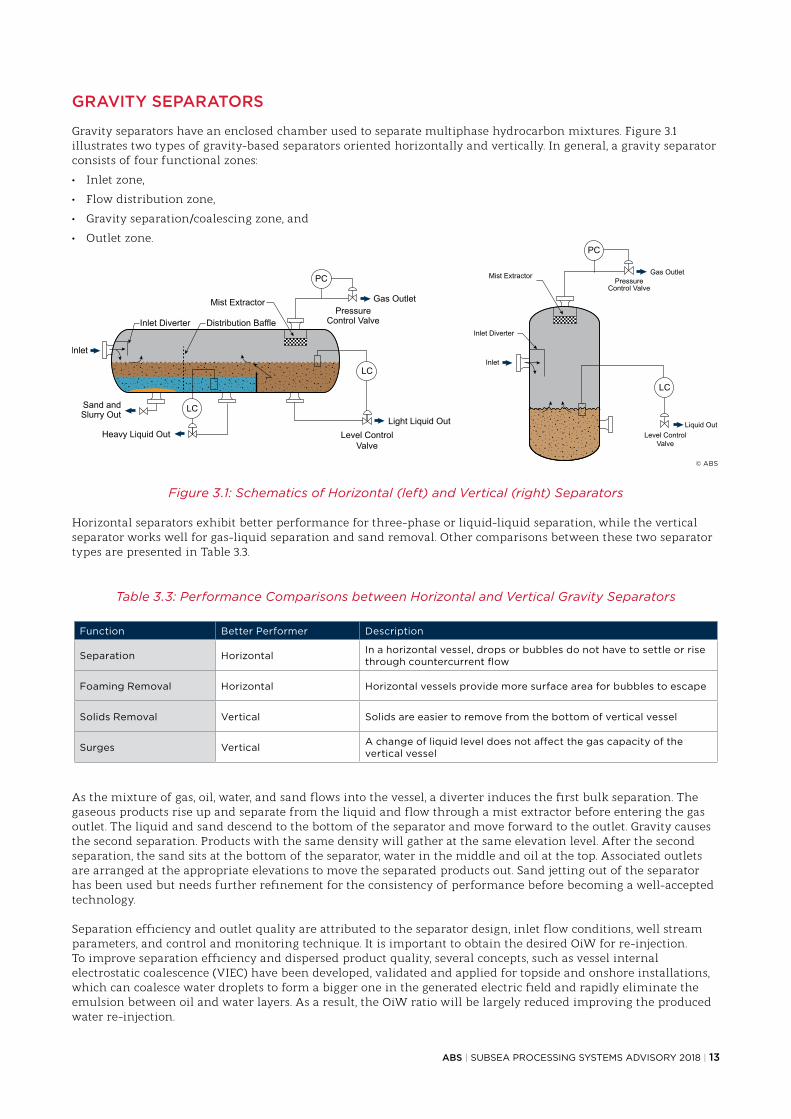
Gravity separators have an enclosed chamber used to separate multiphase hydrocarbon mixtures. Figure 3.1 illustrates two types of gravity-based separators oriented horizontally and vertically. In general, a gravity separator consists of four functional zones:
• Inlet zone,
• Flow distribution zone,
• Gravity separation/coalescing zone, and
• Outlet zone.
Figure 3.1: Schematics of Horizontal (left) and Vertical (right) Separators
Horizontal separators exhibit better performance for three-phase or liquid-liquid separation, while the vertical separator works well for gas-liquid separation and sand removal. Other comparisons between these two separator types are presented in Table 3.3.
Table 3.3: Performance Comparisons between Horizontal and Vertical Gravity Separators
Function Better Performer Description
Separation Horizontal In a horizontal vessel, drops or bubbles do not have to settle or rise through countercurrent flow
Foaming Removal Horizontal Horizontal vessels provide more surface area for bubbles to escape
Solids Removal Vertical Solids are easier to remove from the bottom of vertical vessel
Surges Vertical A change of liquid level does not affect the gas capacity of the vertical vessel
As the mixture of gas, oil, water, and sand flows into the vessel, a diverter induces the first bulk separation. The gaseous products rise up and separate from the liquid and flow through a mist extractor before entering the gas outlet. The liquid and sand descend to the bottom of the separator and move forward to the outlet. Gravity causes the second separation. Products with the same density will gather at the same elevation level. After the second separation, the sand sits at the bottom of the separator, water in the middle and oil at the top. Associated outlets are arranged at the appropriate elevations to move the separated products out. Sand jetting out of the separator has been used but needs further refinement for the consistency of performance before becoming a well-accepted technology.
Separation efficiency and outlet quality are attributed to the separator design, inlet flow conditions, well stream parameters, and control and monitoring technique. It is important to obtain the desired OiW for re-injection. To improve separation efficiency and dispersed product quality, several concepts, such as vessel internal electrostatic coalescence (VIEC) have been developed, validated and applied for topside and onshore installations, which can coalesce water droplets to form a bigger one in the generated electric field and rapidly eliminate the emulsion between oil and water layers. As a result, the OiW ratio will be largely reduced improving the produced water re-injection.
© ABS

14 | SUBSEA PROCESSING SYSTEMS ADVISORY 2018 | ABS
CENTRIFUGAL SEPARATORS
Centrifugal separators use centrifugal force to separate a mixture with different densities. It is more efficient in handling two-phase separation as listed below:
• Liquid-Liquid: De-Waterer
• Gas-Liquid: Phase Splitter, De-Liquidizer, De-Gasser, Scrubber
• Solid-Liquid: De-Sander
Conventional and in-line cyclonic separators are illustrated in Figure 3.2. Both have similar functional zone design consisting of one inlet, one cyclonic body and two outlets. A rotational flow is introduced by a tangential inlet in the conventional cyclone, or by a swirl generator in the in-line cyclone. The centrifugal force acts on the multiphase fluid and moves heavier components outwards where they agglomerate and spiral to the underflow outlet. The lighter components swirl in the center of the cyclone and exit through the overflow outlet.
Figure 3.2: Cyclonic SeparatorLeft: Conventional Cyclone; Right: In-line Cyclone
When assessing solid-liquid separation, separation efficiency is defined as the collection ratios with respect to the minimum collectable particle size, which is affected by the flow rate. See Figure 3.3 for example cyclone separator performance curves. The cyclone dimensions also affect separation performance. Typical subsea cyclonical separators range from 2 inches to 6 inches in diameter.
Figure 3.3: Conventional Cyclone Performance Curves
© ABS
© ABS

ABS | SUBSEA PROCESSING SYSTEMS ADVISORY 2018 | 15
Although the cyclonic separator has advantages with respect to manufacturing and maintenance cost, it has tradeoffs in operational cost and is insufficient to manage inlet flow changes, especially in the case of slugging. Cyclonic separators introduce a large pressure drop due to flow direction change and friction resistance on the cylinder wall, therefore they may require additional boosting equipment and energy for operation, resulting in an increase in the project cost.
OTHER SEPARATION AND TREATMENT TECHNOLOGIES
HYBRID SEPARATION SYSTEMIn order to adapt to the challenges of high pressures in deepwater and to obtain adequate separation performance, industry has developed a hybrid separation system that integrates gravity and centrifugal separators together and benefits from their combined advantages. A series of separation stations are considered instead of a single separation station. One example of the hybrid separation system involves having the gas-liquid separation in an inlet cyclone and liquid-liquid separation in the vessel with reduced diameter to withstand elevated external pressure.
GAS FLOTATION EQUIPMENTIGF, dissolved gas flotation (DGF), or compact flotation units (CFUs) have been widely used in onshore and offshore topside facilities for water treatment. This equipment can deliver OiW values down to 20 ppm and remove solids larger than 10 microns per meter. The general design principle for a gas flotation unit involves the generation of small gas bubbles that adhere to small particles (oil droplets) in produced water and then float to the surface for collection. Industry is working towards a subsea application of gas floatation equipment.
FILTRATION EQUIPMENTFiltration is used to refine produced water by retaining oil droplets that are larger than the filter threshold. Current filtration technology can help reduce OiW values to 5-15 ppm as of date of publication. Medium filtration, membrane filters, and coalescing filters have been used for offshore produced water treatment. When filters have reached their design life or require maintenance, they can either be taken offline and backwashed, or replaced. In addition to produced water treatment, the filtration equipment can also be used for fresh seawater treatment. This technology is now readily available for subsea application, and the filtration performance can be maintained by changing the filter cartridge periodically by a diver or remotely operated vehicle (ROV).
DESIGN
The structural design for the gravity-based separator can follow pressure vessel codes, such as ASME BPVC VIII or EN13445. These codes can also be used to conduct design verification against identified failure modes. For the cyclonic separator, industrial standards such as ASME B31.3, B31.4, B31.8, and API 14E are applicable.
Figure 3.4 shows an example result of a numerical calculation using finite element analysis (FEA) to derive a separator’s structural capacity, against collapse pressure with a given manufacturing ovality of 1% on the section profile.
Figure 3.4: Example of FEA Result of a Separator Under Collapse Pressure
FEAItems
Collapse pressure (Mpa)26.72
(FEA with ovality 1%)
Allowable collapse pressure (Mpa)
17.43(modified by partial safetyfactor, stress conversion,and pressure deduction
factor)
S, MisesSNEG, (fraction = -1.0)(Avg: 75%)
+4.438e+08+4.126e+08+3.814e+08+3.502e+08+3.191e+08+2.879e+08+2.567e+08+2.255e+08+1.943e+08+1.632e+08+1.320e+08+1.008e+08+6.964e+07
© ABS

16 | SUBSEA PROCESSING SYSTEMS ADVISORY 2018 | ABS
——SECTION 4 – SUBSEA BOOSTING SYSTEM
OVERVIEW
For marginal or aging fields, a low wellhead pressure can result in inefficient hydrocarbon production. To solve this problem subsea boosting systems can be used to enable or facilitate production flow. A subsea booster system consists of a boosting module which can be a pump or compressor, along with associated piping, valves, protection structures, control and monitoring modules, power modules, and sometimes a cooling module. Among them, the boosting module is the core piece of equipment, possessing a highly integrated assembly. Since subsea compressors are currently being developed, no industry standards are yet available as of date of publication. This section will only focus on the subsea pumps.
Rotodynamic and rotary displacement are two commonly applied principles for subsea boosting. Rotodynamic boosters use rotating rotors to impart kinetic energy to pump fluid. Rotary displacement boosters use rotors to trap a fixed amount of fluid into an expandable cavity at the intake and force it to be discharged at the discharge pipe with or without the cavity space reduced. Table 4.1 lists these two boosting principles and their associated booster types.
Table 4.1: Popular Boosting Principles and Types
Boosting Principle Booster Types
Rotodynamic
Centrifugal
Helico-Axial
Hybrid
Rotary Displacement
Vane
Lobe
Gear
Multi-screw
For the rotodynamic booster, the helico-axial and centrifugal boosters have undergone numerous qualifications and been extensively used in subsea applications, and possess higher reliability than other types of boosters. Therefore, subsea applications favor the use of rotodynamic boosters. Following subsections provide more details on the centrifugal and helico-axial booster respectively.
For the rotary displacement booster, the twin-screw pump (TSP) is commonly used and works well with viscous well streams. However, since 2007 there have not been any new subsea installations.
The differential pressure (DP) chart in conjunction with gas volume fraction (GVF), as illustrated in Figure 4.1, can be used to guide the selection of booster type. For example, for aqueous single phase flow with GVF up to 15%, the centrifugal booster is recommended for use. For dry gas flow with GVF exceeding 95%, the centrifugal booster is the best option. If the well presents multiphase flow, helico-axial pumps, hydraulic submersible pumps (HSP, powered by hydraulic fluid from topside which is out of the scope of this advisory) and hybrid pumps (a combination of centrifugal and helico-axial impellers) can be selected in accordance with required DP. Since the latest generation of helico-axial pump provides more DP than hybrid pumps, it is unlikely that hybrid pumps will be used for further subsea projects. The operating volume, flow rate, API gravity, viscosity, solid handling, power consumption, reliability, and cost of manufacturing, installation, and maintenance, also need to be taken into account for booster selection.

ABS | SUBSEA PROCESSING SYSTEMS ADVISORY 2018 | 17
Figure 4.1: Pressure Differential vs. GVF
CENTRIFUGAL BOOSTER
Centrifugal boosters are primarily used for single phase flow. They are composed of impellers, volute casings, motors, shafts, housings, seals, bearings, couplings, cooling loops, lubrications, instrumentations, and interfaces. See Figure 4.2 for an example diagram of a boosting module assembled in a highly integrated design which is beneficial for testing, installation, inspection, retrieval, and maintenance.
Figure 4.2: Assembly Diagram of Boosting Module
The working principle of single-stage centrifugal booster is as follows. The fluid enters an impeller through suction eye(s) of the impeller; then it obtains kinetic energy from the rotating impeller that moves fluid radially
350
SPP (Centrifugal)
Helico-Axial
TSP
5,100
4,400
3,625
2,900
2,175
725
0 psi 0 10 20 30 40 50 60 70 80 90 100
300
250
Diff
eren
tial P
ress
ure
200
50
0 bar
150
1,450100
Hybrid
DGC
WGC
SPP Single Phase Pump TSP Twin Screw PumpWGC Wet Gas CompressionDGC Dry Gas Compression
GVF vs. Differential Pressure - Operational and Conceptual Capabilities
Courtesy of INTECSEA
© ABS

18 | SUBSEA PROCESSING SYSTEMS ADVISORY 2018 | ABS
to the volute casing on the circumferential surface. The volute casing is designed to have a transition shape to the discharge pipe with a larger section. As a result, the kinetic energy of the fluid is transferred to potential energy leading to an increase of pressure. To enhance the pressure differential, multiple pairs of impellers and volute casings can be grouped together as the multi-stage booster. Thrust balance is an important design consideration in multi-stage pump design. Two sets of impellers are placed opposite to each other to minimize thrust force along the shaft. An axial thrust compensation device may also be used.
The multi-stage impeller design is commonly used in downhole applications, particularly when there is minimal free gas to be boosted and has been used in ultra-deepwater applications that operate at high pressures to keep gas in solution.
HELICO-AXIAL BOOSTER
The helico-axial booster, also known as “Poseidon Pump”, consists of a series of pumping stages that pressurize the fluid gradually. Each stage is composed of a pair of rotating axial impellers and a stationary diffuser. The working principle of the helico-axial booster is similar to the centrifugal booster. The fluid initially gains kinetic energy from a rotating axial impeller, and then it flows through the diffuser to convert the kinetic energy into potential energy causing an increase in pressure. See Figure 4.3 for a cutaway of helico-axial booster’s impellers.
Although helico-axial boosters work well for multiphase flow, the slug flow with random/patterned pockets of liquid and gas needs to be avoided. The common practice to mitigate this phenomenon is to have the well stream properly homogenized, by a mixer for instance installed upstream of the booster. As the stream flows through the booster, diffusers can re-homogenize the stream and prevent the separation of the oil-gas mixture, resulting in better boosting efficiency. When intended for long-term operation, helico-axial pumps must be able to adapt to the flow changes in GVF and ability to adjust output pressure differential.
Figure 4.3: Cutaway of Helico-Axial Booster’s Impellers
DESIGN
API 17X, API 610, API 676, and other applicable standards provide design recommendations for subsea boosters. When developing the structural design, design by rule methods in API 610 and API 676 are not to be used because those rules are applicable to small diameter pumps with lower pressure. For motor design, induction motors should conform to API 541 and synchronous motors should conform to API 546. Material selection for the pump components are to be compatible with production fluids, chemicals, and seawater they come in contact with. Cathodic protection systems should also be provided. See Table 4.2 for the representative standards and requirements for pump design.
© ABS

ABS | SUBSEA PROCESSING SYSTEMS ADVISORY 2018 | 19
Table 4.2: Representative Design Standards for Boosting Equipment
Items Design codes Items Design codes
Lateral analysis API 610 Coupling API 671
Torsional analysis API 610 Motor design API 17X, 541, 546, 610
Casing rated work pressure API 17X Rotor API 547
Force and moment API 610 Motor cooling system API 17X
Running clearance API 610 Barrier fluid system API 17X
Bearing and bearing housing API 17X Gauge and sensor API 614, 670, 17S
Mechanical shaft seals API 17X Connection API 17H, 6A
Wearing ring API 17X Piping, valve, auxiliaries API 17P, 17R
Thermal analysis Not available Pump module structure API 17P, 17R, 17D
Pump Design Data Sheets, as API 17X Annex C suggests, should be furnished to document design data. Data sheets should include both current and future conditions so that the pump can adapt to these changes over production life. Future conditions may require replacement of pump components, which highlights the importance of pump interface design. Pump design data sheets should include the following items:
• General design requirements
• Operating data
• Fluid descriptions
• Formation water compositions
• Motor design requirements
• Pump instrumentation requirements
• Pump and motor mechanical design output
• Pump design output
• Pump instrumentation outputs
• Barrier fluid/lubrication system design output
• Motor design output

20 | SUBSEA PROCESSING SYSTEMS ADVISORY 2018 | ABS
——SECTION 5 – SUBSEA POWER TRANSMISSION AND DISTRIBUTION SYSTEM
OVERVIEW
As of date of publication, conventional power systems transfer large amount of electrical power to major subsea equipment in a point-to-point manner. When additional subsea equipment needs to be added to the system at later stages of field life, such as in the case of secondary recovery, conventional power systems show low flexibility and little scalability to expand their functions to accommodate new equipment due to the limited topside space. Newly proposed subsea power system concepts use a single power cable or an umbilical to transmit electrical power to the seafloor and distribute power to multiple points throughout the subsea infrastructure. A schematic of the subsea power system is depicted in Figure 5.1, illustrating subsea transformer, subsea switchgear and distributor, and subsea VSDs. This concept is going through technology qualification programs to verify the functional requirements of transferring, converting, distributing, regulating, and controlling electrical power as well as system integrity under different loading scenarios.
Figure 5.1: Example of Subsea Power System
Subsea power transmission and distribution configurations are classified into five categories based on the power rating, step-out distance, and power facilities as illustrated in Figure 5.2. As of date of publication, a type five system that uses a subsea ASD (adjustable speed drive) is rated TRL 4.
Figure 5.2: Power Step-out Categories
© Siemens AG
Note: XFMRS: Transformers
Courtesy of INTECSEA

ABS | SUBSEA PROCESSING SYSTEMS ADVISORY 2018 | 21
Table 5.1 provides the maximum power ratings for available subsea equipment and systems as of date of publication, which can be used to estimate the required power for a subsea field. It is noted that compressors and pumps (including downhole ESP) demand the highest power, while pipeline heating, which is used to assure flow, can also consume considerable energy especially for long tie-backs. Control systems and electrostatic coalescers (installed within a separator) consume minimal power.
Table 5.1: Maximum Power Ratings for Available Subsea Equipment and System
Equipment UnitMaximum Power
Consumption (KW)
Compressor 12,500
Pump 6,000
Pipeline Heating (per km) 675
Electrostatic Coalescer 100
Control System 50
Although the use of new subsea power system concept could minimize overall costs for both greenfield and brownfield developments, some negative factors need to be considered and properly managed, such as higher up-front investment, higher risk on integrity management, and cost of intervention.
SUBSEA TRANSFORMER
Transformers are very useful for power transmission and distribution. A subsea transformer should not only be robust enough to withstand external pressure, but also able to operate with minimal or zero maintenance. Subsea transformers are considered a field proven technology with more than 20 underwater installations to date. See Figure 5.3 for examples of subsea transformers.
Figure 5.3: Example of Subsea Transformer
Subsea transformers usually utilize either a single or double shell box. They are filled with liquid; and, if applicable, use pressure compensation to balance the differential pressure and prevent the transformer shell from collapsing. Necessary cooling is provided by seawater. Subsea electrical power standardization (SEPS) SP-1002 provides design guidance for subsea transformers, and proposes a technical data sheet for documenting general descriptions, mechanical parameters, environment data, dielectric liquid parameters, cooling and temperature limits, construction material, tank design, handling and installation requirements, electrical parameters, current harmonic spectrum, testing, instrumentation and auxiliary systems, and accessories.
© ABB

22 | SUBSEA PROCESSING SYSTEMS ADVISORY 2018 | ABS
SUBSEA SWITCHGEAR
Switchgear is a combination of electrical switches, distributor, fuses or circuit breakers used to control, protect, and isolate downstream electrical equipment. It is intended to distribute electrical power to individual subsea equipment. As of date of publication, the subsea switchgear concept has been validated in a lab environment; but no field installation has been completed. See Figure 5.4 for an example of subsea switchgear.
Figure 5.4: Example of Subsea Switchgear
SUBSEA VARIABLE SPEED/FREQUENCY DRIVE (VSD/VFD)
VSDs and VFDs are a type of adjustable speed drive used in electro-mechanical drive systems to control AC motor speed and torque by varying motor input frequency and voltage. As of date of publication, the subsea VSD concept has only been validated in lab environments. See Figure 5.5 for an example of subsea VSD.
Figure 5.5: Example of Subsea VSD
© Siemens AG
© Siemens AG

ABS | SUBSEA PROCESSING SYSTEMS ADVISORY 2018 | 23
SUBSEA UPS
Subsea UPSs can provide uninterrupted power to critical modules for a pre-determined time to mitigate critical failure or loss of function during a power outage. Magnetic levitating bearings of motor and impeller shafts, subsea production communication, instrumentation and monitoring equipment are examples of critical modules that can be protected by the UPS allowing fail-safe operation during an emergency shut-down (ESD).
A Subsea UPS consists of three main components: battery bank, controller and a battery charging module. As of date of publication, industry can accommodate subsea UPS battery capacities of up to 690V AC/15.5A or 375V DC/75A per unit providing 150 kWh or 40 kWh respectively. However, it can be scaled up by configuring in a daisy-chain or hub arrangement.
POWER CONNECTORS AND PENETRATORS
There are three distinct types of cable connecting devices: dry-mate connectors (DM), wet-mate connectors (WM), and penetrators (PEN).
• Dry-mate connectors are made up at surface and then installed subsea in seawater. They are sealed to allow operation under water; however, the powered equipment must be recovered to the surface for connection/reconnection.
• Wet–mate connectors are submersible and can be connected/disconnected (with the power off) in a submerged condition.
• Penetrators enable high voltage (HV) conductors to pass through partitions such as a wall or tank. The means of attachment flange or fixing device, to the partition, forms part of the penetrator. Penetrators generally have fewer seals than connectors since they are intended to hard wire the cable to equipment permanently, and are not designed for disconnection, which make them less flexible in comparison to connectors.
SUBSEA POWER CABLE
The power cable or power umbilical is used to transmit electrical power between surface/onshore facilities and subsea equipment. Power cables consist of conductors, insulation, fillers, metallic layers, metallic screens, metallic sheaths, metallic armors, and oversheaths. IEC 60502-1 IEC 60502-2 and Cigre TB 490, where applicable, can be used as design guidance for high voltage or extra high voltage power cables.
Dynamic power cable design (parts of cable free to move and/or not resting on the seabed) is a technology challenge in deepwater application. The PowerCab JIP has succeeded in optimizing cross-section to achieve extended fatigue life by lightweight design for power cables rated at 100 MW, 132kV, 525A and used in 2000 m water depth. See Figure 5.6 for a multicore subsea power cable design from the PowerCab JIP.
In addition to dynamic fatigue, qualification programs have been performed to explore the best arrangement of power conductors to minimize induced voltages, harmonics, etc. The results suggest that in general, a triangle (triad) arrangement for single 3-phase circuits or an extension with more than single 3-phase circuits reduces undesirable effects mentioned above.
Figure 5.6: Example of Subsea Power Cable Design
© BPP-Cables

24 | SUBSEA PROCESSING SYSTEMS ADVISORY 2018 | ABS
DESIGN
The IEEE/IEC 61886 committee has a roadmap to develop design requirements for subsea transformers, electrical power transmission and distribution, medium voltage (MV) penetrators and connectors, and static and dynamic subsea cables. Subsea switchgear and subsea VSDs have been validated in lab environments. Currently, the Subsea Electrical Power Standardization (SEPS) JIP is developing the design guidance for subsea power equipment and components as the date of the publication.
General challenges associated with subsea power systems include:
• Minimization of component designs without losing flexibility for future field modification
• Performance of electrical simulations under all loading conditions
• Designing robust and durable water blocking and sealing technologies
• Development of pressure compensation and barrier technologies
• Minimization of electric power transmission loss
• Mitigation of current harmonics
• Meeting required design life
• Prevention of AC corrosion
• Mitigation of electromagnetic field (EMF) effects on the surrounding infrastructure.
• Minimization of cost of assembly, installation and retrieval

ABS | SUBSEA PROCESSING SYSTEMS ADVISORY 2018 | 25
——SECTION 6 – SUBSEA CONTROL AND MONITORING SYSTEM
OVERVIEW
The subsea control and monitoring system is used to preserve the operational integrity of production and processing activities under any condition. It provides the functions of data monitoring and collection, data communication, data processing, and control engagement. Highly customized hardware and software are designed to perform required functions seamlessly in accordance with field conditions and system architecture. API 17F contains detailed technical information for subsea control and monitoring system that is applicable to SPRS. See Figure 6.1 for an example of the control and monitoring system of the Troll C processing project, which includes a subsea separator and reinjection pump.
Figure 6.1: Schematic of Control and Monitoring System of Troll Pilot Field
This section focuses on the produced water instrumentation and wireless communication methods, which are two key topics for subsea processing projects.
PRODUCED WATER INSTRUMENTATION
Produced water is a mixture of formation water and injected water, with a complex chemistry. It also contains varying amounts of oil and condensate. Regulations worldwide, see Appendix B, impose different OiW concentration limits on produced water discharge. OiW measurements include direct and indirect methods. EPA Method 1664 directly measures the weight of the extractable substances per liter of sample retrieved from the production facility by ROV. This method can be very costly as the tests need to be conducted in an accredited lab once a month. Alternatively, the industry prefers indirect methods which use a variety of instruments and technologies to measure OiW with appropriate calibration to EPA Method 1664. Table 6.1 shows produced water instrumentation technologies, their measurement capacities, and application status. As of date of publication, the light scattering instrument is the only technology that has been used in an actual subsea project in Marlim, offshore Brazil.
© ABS

26 | SUBSEA PROCESSING SYSTEMS ADVISORY 2018 | ABS
Table 6.1: Produced Water Instrumentation Technologies
Technology Oil in Water Solid Content Particle Size and Distribution
Topside Application
Subsea Application
Light Scattering X X X
Ultrasonic X X X X
MS* X X X X
LIF* X X
UV* Fluorescence X X
Photo Acoustic X Developing
NMR* X X Developing
Confocal LIF & MS X X X Developing
LIF and MS X X X Developing
*MS: Microscopy; LIF: Laser induced fluorescence; UV: Ultraviolet; NMR: Nuclear magnetic resonance
WIRELESS COMMUNICATION METHODS
Subsea communication methods can be categorized according to their signal types and transmission media. There are three major categories used by the industry: conductor cable, fiber optics, and wireless. Conductor cable and fiber optics are mature technologies and are widely applied in field. Wireless communication is an increasingly attractive option due to its potential advantages of low installation cost, high flexibility, and high scalability. A comparison between wireless and other communication methods is listed in Table 6.2.
Table 6.2: Communication Methods Comparisons
Attributes Wireless Conductor Cable Fiber Optics
Bandwidth See Figure 6.2100 Mb/sec
Maximum tolerable bandwidth: 50 MHz/Km
Above 10Gb/sec
Attenuation Very high Very high Extremely low (<0.2 dB/Km)
Distance See Figure 6.2 Dependent on the umbilical distance 200km without amplification
Weight No cable weight Twice the fiber optics for the same capacity Light weight
Corrosion Corrosion free Prone to corrosion when not protected from water ingress Resistant to corrosion
HPHT* Application Appropriate for HPHT May fail due to lengthy exposure to HPHT Appropriate for HPHT
Major Concerns Interference from EMI* and RFI*Short transmission distance
Interference from EMI and RFISeawater ingress
may lead to fire outbreakHigh CAPEX
*HPHT: High pressure, high temperature; RFI: Radio frequency interference; EMI: Electromagnetic interference
There are three types of wireless communication:
• Acoustic
• Optical
• Radio frequency (RF)
Using current technology, wireless data transmission between surface and deepwater seabed is possible using acoustic and radio methods. Optical wireless is suitable for short distance communication (several to dozens of meters) such as between a subsea device and a ROV. However, environmental conditions can dramatically influence communication performance.
Wireless communications require low power to function. For these components, industry has integrated batteries to power up wireless communication modules and instrument devices, so that the assembly can then be installed at any location without requiring a flying lead. ROV-accessible rechargeable batteries may also become a viable option which can further improve longevity and make wireless communications a more attractive design option.

ABS | SUBSEA PROCESSING SYSTEMS ADVISORY 2018 | 27
Subsea wireless communication’s broadband, range, and available operating time driven by battery are illustrated in Figure 6.2.
Figure 6.2: Subsea Wireless Communication Performance
© WFS Technologies

28 | SUBSEA PROCESSING SYSTEMS ADVISORY 2018 | ABS
——SECTION 7 – ABS ROLE Verification and validation plays an important role in the safe and reliable operation of subsea production and processing systems. While subsea systems are expected to deliver high levels of operational reliability, leveraging established classification societies’ processes for verification and validation offers significant benefits.As a classification society, ABS establishes and applies technical standards in the form of Rules and Guides for the design, construction and survey of marine related facilities including ships, offshore units and subsea systems. These Rules and Guides form a foundation for developing processes to conduct reviews to verify asset integrity. These processes can then be used to develop a complete list of verification and validation activities to be followed to achieve compliance.
ABS has been actively engaged in the development of technical standards for subsea systems through its internal research and development programs. ABS also participates in standards development organizations including API, ISO and IEEE. Table 7.1 lists selected key ABS publications for subsea systems.
Table 7.1: ABS Subsea Publications List
Focus Area Publication Title
Subsea Production System Guide for Classification and Certification of Subsea Production Systems
Technology Qualification Guidance Notes on Qualifying New Technologies
PipelineGuide for Building and Classing Subsea Pipeline Systems
Guidance Notes on Subsea Pipeline Route Determination
Riser
Guide for Building and Classing Subsea Riser Systems
Guidance Notes on Subsea Hybrid Riser Systems
Guidance Notes on Drilling Riser Analysis
Through its global network of engineering and survey teams, ABS offers the following independent third party services for subsea processing systems:
• Design verification (design review) and design validation (survey during manufacturing)
• Installation/commissioning verification
• In-service examination
• Life extension assessment
• Decommissioning verification
• New Technology Qualification (NTQ)
The development of subsea processing systems introduces many new technologies with little or no precedent and may be so different from existing designs that raises questions about readiness, maturity and safety. The ABS NTQ program offers an approach for qualification of such new technologies to confirm their ability to perform intended functions in accordance with defined performance requirements. This facilitates early adoption and efficient implementation – demonstrating level of maturity – and that potential risks have been systematically reviewed.

ABS | SUBSEA PROCESSING SYSTEMS ADVISORY 2018 | 29
——SECTION 8 – SUMMARY Deepwater production remains an essential part of the global energy mix and economically viable projects continue to progress. To maintain competitiveness, the offshore industry continually evaluates ways to optimize system designs and streamline operations with OPEX/CAPEX-reducing solutions. Subsea processing systems are increasingly being considered as a cost-effective solution for both brownfield and greenfield developments. The benefits of an SPRS include the potential for reducing CAPEX and OPEX associated with topside facilities, increased design flexibility, improved recovery and production rates, extended field life, reduction of flow assurance problems, debottleneck of topside water treatment constraints, reduction of energy consumption for produced water, and minimization of manual operation associated with a topside facility.
As the industry increases reliance on these systems, there are still some technical challenges that need to be overcome before wider adoption is possible. Some of these challenges include the effects of external pressure on SPRS design, long-distance power transmission/distribution, and optimized monitoring and control systems. While the industry is actively addressing these challenges, near-term field applications primarily focus on subsea boosting systems and components for enhanced oil recovery, increasing tie-back distances and extending field life. As part of this effort, ABS is dedicated to supporting the industry in advancing the development of subsea processing technologies and their implementation. This advisory serves as the first in a series of publications on subsea processing.
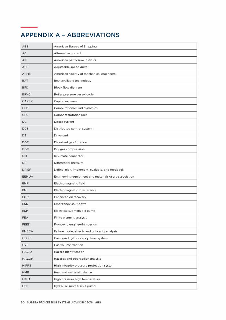
30 | SUBSEA PROCESSING SYSTEMS ADVISORY 2018 | ABS
——APPENDIX A – ABBREVIATIONS
ABS American Bureau of Shipping
AC Alternative current
API American petroleum institute
ASD Adjustable speed drive
ASME American society of mechanical engineers
BAT Best available technology
BFD Block flow diagram
BPVC Boiler pressure vessel code
CAPEX Capital expense
CFD Computational fluid dynamics
CFU Compact flotation unit
DC Direct current
DCS Distributed control system
DE Drive end
DGF Dissolved gas flotation
DGC Dry gas compression
DM Dry-mate connector
DP Differential pressure
DPIEF Define, plan, implement, evaluate, and feedback
EEMUA Engineering equipment and materials users association
EMF Electromagnetic field
EMI Electromagnetic interference
EOR Enhanced oil recovery
ESD Emergency shut down
ESP Electrical submersible pump
FEA Finite element analysis
FEED Front-end engineering design
FMECA Failure mode, effects and criticality analysis
GLCC Gas-liquid cylindrical cyclone system
GVF Gas volume fraction
HAZID Hazard identification
HAZOP Hazards and operability analysis
HIPPS High integrity pressure protection system
HMB Heat and material balance
HPHT High pressure high temperature
HSP Hydraulic submersible pump

ABS | SUBSEA PROCESSING SYSTEMS ADVISORY 2018 | 31
HSQE Health, safety, quality and environmental
HV High voltage
ICSS Integrated control and safety system
IEC International electrotechnical commission
IEEE Institute of electrical and electronics engineers
IGF Induced gas flotation
IP Intermediate pressure
ISO International standards organization
KP Key process
LIF Laser induced fluorescence
LP Low pressure
MS Microscopy
MV Medium voltage
NACE National association of corrosion engineers
NDE Non drive end
NPDES National pollutant discharge elimination system
NMR Nuclear magnetic resonance
NTQ New technology qualification
OiW Oil in water
OPEX Operating expense
OST (Russian’s) State standard in English
P&ID Piping and instrumentation diagram
PEN Penetrator
PFD Process flow diagram
PS Produced sand
PW Produced water
RAM Risk assessment matrix
RF Radio frequency
RFI Radio frequency interference
RIM Reliability and integrity management
ROV Remote operated vehicle
SAFE Safety analysis function evaluation
SCM Subsea control module
SEPS Subsea electrical power standardization
SIL Safety integrity level
SIS Safety instrumented system
SPP Single phase pump
SPRS Subsea processing system
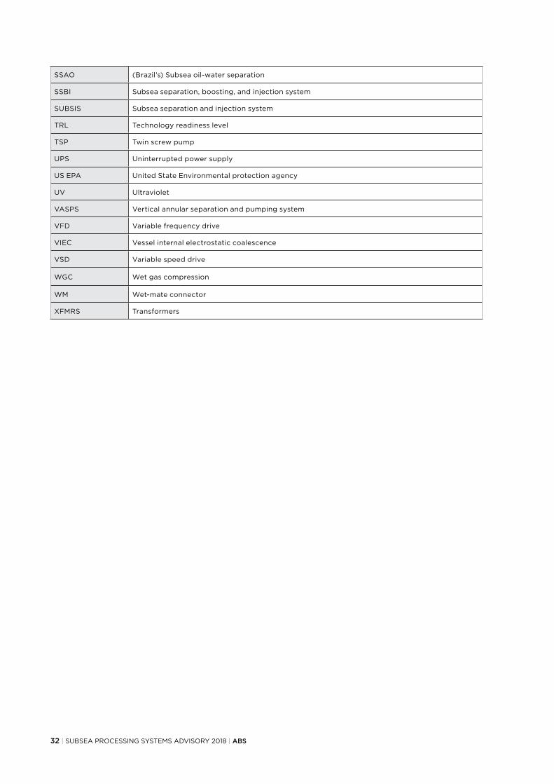
32 | SUBSEA PROCESSING SYSTEMS ADVISORY 2018 | ABS
SSAO (Brazil’s) Subsea oil-water separation
SSBI Subsea separation, boosting, and injection system
SUBSIS Subsea separation and injection system
TRL Technology readiness level
TSP Twin screw pump
UPS Uninterrupted power supply
US EPA United State Environmental protection agency
UV Ultraviolet
VASPS Vertical annular separation and pumping system
VFD Variable frequency drive
VIEC Vessel internal electrostatic coalescence
VSD Variable speed drive
WGC Wet gas compression
WM Wet-mate connector
XFMRS Transformers

ABS | SUBSEA PROCESSING SYSTEMS ADVISORY 2018 | 33
——APPENDIX B – REFERENCES
API Standards/Recommended Practice/Specification
17A Design and Operation of Subsea Production Systems-General Requirements and Recommendations
17B Recommended Practice for Flexible Pipe
17D Design and Operation of Subsea Production Systems-Subsea Wellhead and Tree Equipment
17E Specification for Subsea Umbilicals
17F Standard for Subsea Production Control Systems
17H Remotely Operated Vehicle (ROV) Interfaces on Subsea Production Systems
17I Installation guidelines for Subsea Umbilicals
17N Recommended Practice on Subsea Production System Reliability, Technical Risk, and Integrity Management
17O Subsea High Integrity Pressure Protection System (HIPPS)
17P Design and Operation of Subsea Production Systems - Subsea Structures and Manifolds
17Q Subsea Equipment Qualification-Standardized Process for Documentation
17R Recommended Practice for Flowline Connectors and Jumpers
17S Recommended Practice for the Design, Testing, and Operation of Subsea Multiphase Flow Meters
17U Recommended Practice for Wet and Dry Thermal Insulation of Subsea Flowlines and Equipment
17V Recommended Practice for Analysis, Design, Installation, and Testing of Safety Systems for Subsea Applications
17X Recommended Practice for Subsea Pump Module Systems (draft)
17TR4 Subsea Equipment Pressure Ratings
17TR5 Avoidance of Blockages in Subsea Production Control and Chemical Injection Systems
17TR6 Attributes of Production Chemicals in Subsea Production Systems
17TR7 Verification and Validation of Subsea Connectors
17TR8 High-pressure High-temperature Design Guidelines
17TR9 Umbilical Termination Assembly (UTA) Selection and Sizing Recommendations
17TR10 Subsea Umbilical Termination (SUT) Design Recommendations
17TR11 Pressure Effects on Subsea Hardware During Flowline Pressure Testing in Deep Water
17TR12 Consideration of External Pressure in the Design and Pressure Rating of Subsea Equipment
17TR13 General Overview of Subsea Production Systems
17TR15 API 17H Hydraulic Interfaces for Hot Stabs
5C3 Technical Report on Equations and Calculations or Casing, Tubing, and Line Pipe Used as Casing or Tubing; and Performance Properties Tables for Casing and Tubing
5LCP Specification for Coiled Line Pipe
6A Specification for Wellhead and Christmas Tree Equipment
520 Sizing, Selection, and Installation of Pressure-Relieving Devices in Refineries, Parts I & II
526 Flanged Steel Pressure-relief Valves
541 Form-wound Squirrel Cage Induction Motors—375 kW (500 Horsepower) and Larger
546 Brushless Synchronous Machines—500 kVA and Larger
547 General-purpose Form-wound Squirrel Cage Induction Motors-250 Horsepower and Larger
579 Fitness-For-Service
610 Centrifugal Pumps for Petroleum, Heavy Duty Chemical, and Gas Industry Services
614 Lubrication, Shaft-sealing and Oil-control Systems and Auxiliaries

34 | SUBSEA PROCESSING SYSTEMS ADVISORY 2018 | ABS
API Standards/Recommended Practice/Specification
671 Special-Purpose Couplings for Petroleum, Chemical, and Gas Industry Services
675 Positive Displacement Pumps—Controlled Volume For Petroleum, Chemical, And Gas Industry Services
676 Positive Displacement Pumps—Rotary
682 Pumps-Shaft Sealing Systems for Centrifugal and Rotary Pumps
685 Seamless Centrifugal Pumps for Petroleum, Heavy Duty Chemical, and Gas Industry Process Services
686 Machinery Installation and Installation Design
1104 Welding of Pipelines and Related Facilities
1110 Recommended Practice for the Pressure Testing of Steel Pipelines for the Transportation of Gas, Petroleum Gas, Hazardous Liquids, Highly Volatile Liquids, or Carbon Dioxide
1160 Managing System Integrity for Hazardous Liquid Pipelines
ISO
1940-1 Mechanical vibration -- Balance quality requirements for rotors in a constant (rigid) state -- Part 1: Specification and verification of balance tolerances
9712 Nondestructive testing -- Qualification and certification of personnel
13628 Most documents in 13628 series are identical to that of API 17 series
14224 Petroleum, petrochemical and natural gas industries. Collection and exchange of reliability and maintenance data for equipment
17766 Centrifugal pumps handling viscous liquids — Performance corrections
17782 Petroleum, petrochemical and natural gas industries -- Qualification of manufacturers of special materials
ASME
BPVC VIII Rules for Construction of Pressure Vessels
B31.3 Process Piping
B31.4 Pipeline Transportation Systems for Liquids and Slurries
B31.8 Gas Transmission and Distribution Piping Systems
B31G Manual for Determining the Remaining Strength of Corroded Pipelines
NORSOK standards/recommended Practice/Specification
M-001 Material Selection
M-650 Qualification of manufacturers of special materials
U-001 subsea production system
U-009 subsea system life extension
British standards/recommended Practice/Specification
PD 8010 series Subsea Pipeline systems
BS EN ISO 13628 Identical to ISO 13628 series
BS EN ISO 14723 Subsea pipeline valves
BS 7910 Guide to methods for assessing the acceptability of flaws in metallic structures
Others
EEMUA 194 Guidelines for materials selection and corrosion control for subsea oil and gas production equipment
IEC 60085 Electrical insulation - Thermal evaluation and designation
IEEE 61886-1 Subsea equipment - Power connectors, penetrators and jumper assemblies with rated voltage from 3 kV (Umax = 3,6 kV) to 30 kV (Umax = 36 kV) (Under Development)
NACE MR 0103 Materials Resistant to Sulfide Stress Cracking in Corrosive Petroleum Refining Environments
NEMA MG 1-2014 Motors and Generators

ABS | SUBSEA PROCESSING SYSTEMS ADVISORY 2018 | 35
——APPENDIX C – REGULATIONS
REGULATIONS FOR SUBSEA PROCESSING SYSTEMS
Country Applicable Regulation Notes
U.S.
30 CFR part 250, Subpart H Addresses requirements for subsea processing including gas lift, pump and water injection systems.
NTL 2011-N11Provides guidance and clarification on the regulatory requirements for safe and environmentally sound use of subsea pumping as a recovery method in subsea development projects.
Brazil ANP Resolution No. 41 Provides the technical regulations for establishing a subsea operational safety management system (SGSS) including subsea processing systems.
REGULATION/AGREEMENT ON OFFSHORE EFFLUENT DISCHARGE
Country/Region Regulation/Agreement Offshore Effluent Discharge Requirement
U.S. 40 CFR 435PW*: Daily maximum 42 mg/L; monthly average 29mg/LToxicity: per 40 CFR 435PS*: Prohibited
Brazil Not available PW: Daily maximum 20 mg/L
Canada Offshore waste treatment guidelines
PW: Daily maximum 44 mg/L; monthly average 30 mg/LPS: Acceptability of the discharge of produced sand will depend on the concentration of oil in the produced sand and its aromatic content
China GB 4914-85 PW: Daily maximum 75 mg/L; monthly average 30-50 mg/L
RussiaOST 39-225-88 (industrial standard); Baltic sea convention
PW: OST regulates requirement of produced water for reinjection: maximum 50 mg/L PW: Offshore discharge per Baltic sea convention
Norway OSPARCOMThe Activities Regulations
PW: Per OSPARCOMPS: Produce sand and other solid particles shall not be discharged to sea if the content of formation oil, other oil or base fluid in organic drilling fluid exceeds ten grams per kilo of dry mass.
U.K. OSPARCOM PW: per OSPARCOM
Oslo-Paris commission OSPARCOM PW: Daily maximum 30 mg/L
Toxicity: Whole effluent assessment method
Baltic sea convention HELCOM PW: Daily maximum 15 mg/L or 40 mg/L if BAT cannot be achieved
Barcelona convention Barcelona convention PW: Daily maximum 100 mg/L, monthly average 40 mg/L
Kuwait convention Kuwait convention PW: Daily maximum 100 mg/L, monthly average 40 mg/L
World Bank PS: Ship to shore or reinjection is preferred; discharge is prohibited unless oil concentration is less than 1% by weight on dry sand.
*PW: Produced water; PS: Produced sand

TX 07/18 18181
© Vismar UK/Shutterstock
CONTACT INFORMATION
NORTH AMERICA REGION16855 Northchase DriveHouston, Texas 77060, USATel: +1-281-877-6000Email: [email protected]
SOUTH AMERICA REGIONRua Acre, nº 15 - 11º floor, CentroRio de Janeiro 20081-000, BrazilTel: +55 21 2276-3535Email: [email protected]
EUROPE AND AFRICA REGIONABS House, No. 1 Frying Pan AlleyLondon E1 7HR, UKTel: +44-20-7247-3255Email: [email protected]
MIDDLE EAST REGIONAl Joud Center, 1st floor, Suite # 111 Sheikh Zayed RoadP.O. Box 24860, Dubai, UAETel: +971 4 330 6000Email: [email protected]
GREATER CHINA REGION5th Floor, Silver Tower No. 85 Taoyuan Road, Huangpu DistrictShanghai 200021, P.R. ChinaTel: +86 21 23270888Email: [email protected]
NORTH PACIFIC REGION11th Floor, Kyobo Life Insurance Bldg.7, Chungjang-daero, Jung-GuBusan 48939, Korea, Republic ofTel: +82 51 460 4197Email: [email protected]
SOUTH PACIFIC REGION438 Alexandra Road#08-00 Alexandra Point, Singapore 119958Tel: +65 6276 8700Email: [email protected]
© 2018 American Bureau of Shipping. All rights reserved.