subsea manifold design for pendulous installation
TRANSCRIPT

SUBSEA MANIFOLD DESIGN FOR PENDULOUSINSTALLATION METHOD IN ULTRA DEEP WATER
Mario L. P. G. RibeiroFMC CBV Subsea
Milton V. B. SeguraFMC CBV Subsea
José A. N. FerreiraPETROBRAS

Summary
• Subsea manifold main features and components
• Current manifold installation methods
• P52 manifold design
• Manifold structural analysis – FEA
• Hydrodynamic analysis
• Closing remarks

Subsea Manifold
• Functions:– Oil production
– Gas production
– Gas lift injection
– Water injection
• Objectives:– Optimize the subsea layout arrangement
– Reduce flowlines cost
– Reduce the quantity of risers connected to the platform
– Full production in advance

More than 20 Diverless Subsea ManifoldsManufactured in Brazil
1997 Albacora Phase 25 Unit. – 400m WD
2001 Namorado
1 Unit. - 200m WD
2004Marimbá Leste
1 Unit. – 715m WD
2004Viola
1 Unit. – 300m WD
2002 Bijupira & Salema5 Unit. – 800 WD 2006
Roncador Phase 2 –2 Manifolds on going
1998 Marlim
2 Unit. – 820m WD
1996 Albacora Phase 12 Unit. – 640m WD
2002 Roncador Phase 1
1 Unit. – 1,892m WD
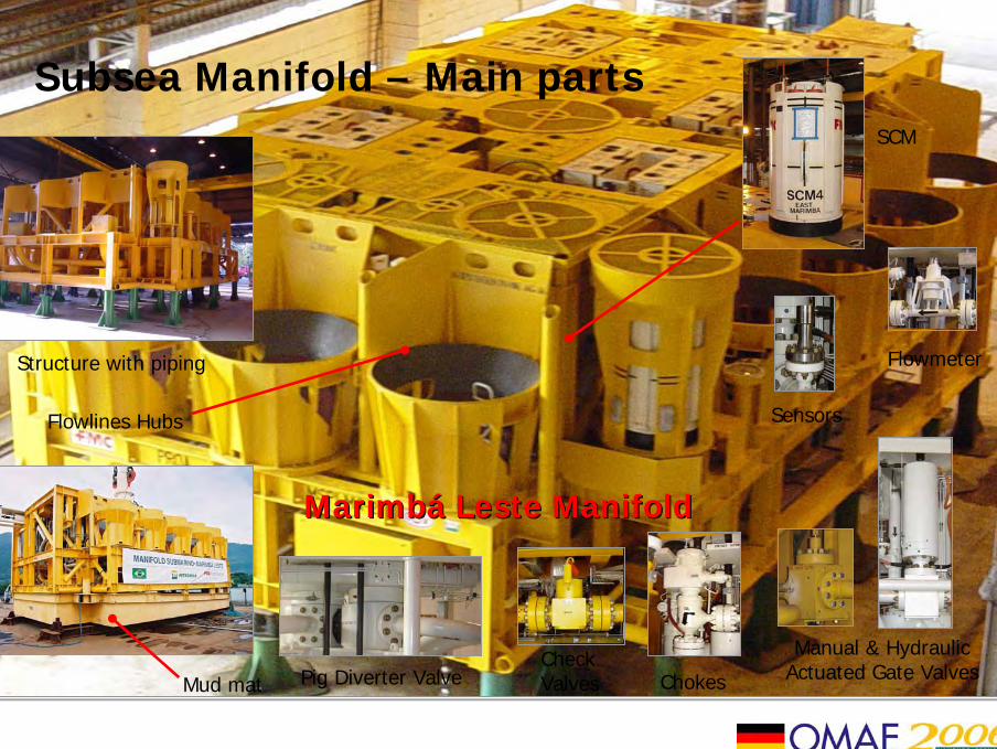
Subsea Manifold – Main parts
MarimbáMarimbá Leste Leste ManifoldManifold
Structure with piping
Mud mat
Flowlines Hubs
ChokesCheckValves
Manual & Hydraulic Actuated Gate ValvesPig Diverter Valve
SCM
Flowmeter
Sensors
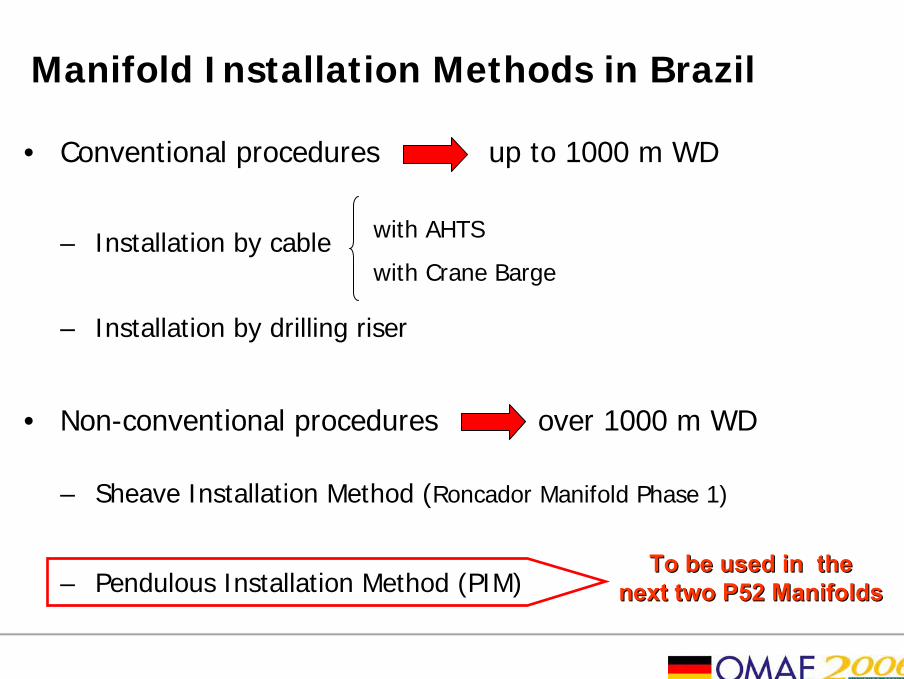
Manifold Installation Methods in Brazil
• Conventional procedures up to 1000 m WD
– Installation by cable
– Installation by drilling riser
• Non-conventional procedures over 1000 m WD
– Sheave Installation Method (Roncador Manifold Phase 1)
– Pendulous Installation Method (PIM)
with AHTS
with Crane Barge
To be used in the To be used in the next two P52 Manifoldsnext two P52 Manifolds

Conventional Installation Methods
• Work wire (w/o heave motioncompensation)
• Drilling Riser
AHTS
CraneBarge

Sheave Installation Method
• Offshore facilities:– SS rig: Provides heave motion
compensation
– AHTS 1: Lift the Manifold together with the SS rig
– AHTS 2: Orient the Manifold
AHTS 2 SS rig
AHTS 1
Roncador Manifold 11885m WD

Pendulous Installation Method
• By pendulous – Barge and AHTS
FFUULLLL
SSCCAALLEE
TTEESSTT

P52 Manifold
• Dimensions: 16.5m (L) x 8.5m (W) x 5.2m (H)
• Weight in air: 280 tons
• WD installation: 1900m
• CG: 3.15m
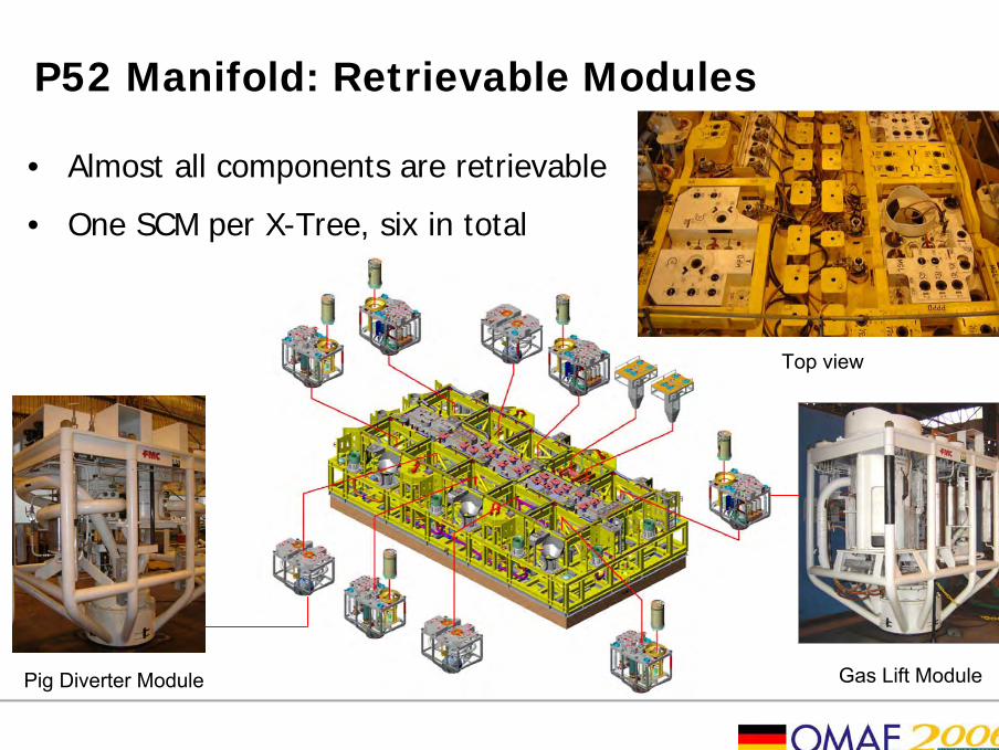
P52 Manifold: Retrievable Modules
• Almost all components are retrievable
• One SCM per X-Tree, six in total
Top view
Gas Lift ModulePig Diverter Module

P52 Manifold: SCM
• Subsea Control Module (SCM)– Electrical components: vibrations and pressure rate

Manifold Structural Analysis – FEA
• Structure life– Construction steps: manufacture, assembly, integration test
– Road and sea transportation
– Installation
– Operation
• Loads– Permanent loads
– Operational loads
– Enviroments loads
• Dynamic Amplification
Factor (DAF): 2

Manifold Structural Analysis – Global Model
• Global model: AISC - LRFD checking
Lifting condition: AISC checking for axial load plus bending moment

Manifold Structural Analysis – Local Model
• Local model: von Mises checking – 60% of yield strength – 345Mpa
Lifting condition: von Mises stress distribution (MPa)

Hydrodynamic analysis
• Excessive Oscillations (initial instability)
Hydrodynamic effect
CG positionMunk effectDragLiftVortex shedding

Hydrodynamic analysis (Cont.)
• Increase hydrodynamic stability– additional buoyancy in the line installation (1)
– a hydrodynamic-adapted geometry, e.g., vertical or near vertical panels around equipment (2) and open holes in the mud mat (3)
– dead weight at the manifold mud mat
(1)
(2) (3)
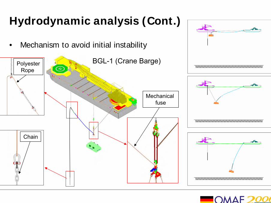
Hydrodynamic analysis (Cont.)
• Mechanism to avoid initial instability
Mechanical fuse
PolyesterRope
Chain
BGL-1 (Crane Barge)


Closing Remarks
• For increasing the manifold reliability most of all components are retrievable;
• The assumed value for DAF (2) is enough to cover all the operational conditions;
• SCM supports installation loads;
• Counterweight is essential for avoid oscillations;
• Additional work for next manifold project is required in order to develop a “hydrodynamic structurehydrodynamic structure” to avoid the excessive oscillations during initial moments.

21
THANK YOUTHANK YOU