submission doc.: ieee 11-14/0904r0 july 2014 fan bai, general motorsslide 1 in-cabin wifi channel...
TRANSCRIPT

Submission
doc.: IEEE 11-14/0904r0July 2014
Fan Bai, General MotorsSlide 1
In-Cabin WiFi Channel Channel: Preliminary Ray Tracing Simulations
Date: 14-July-2014
Name Affiliations Address Phone email
Fan Bai General Motors 586 986 1457
Lin Cheng* Trinity College 860 297 4117
James Casazza* FordDirect
James Grace* Panasonic Auto System
Igal Kotzer General Motors [email protected]
Dan Stancil* NC State Univ. 919 513 3606
Authors:
* The contributors were with Carnegie Mellon University when the research project was conducted.
Submission
doc.: IEEE 11-14/0904r0
Fan Bai, General Motors
Wireless on the go
Source: http://www.internet-go.com/
July 2014
Slide 2
Submission
doc.: IEEE 11-14/0904r0
Fan Bai, General Motors
Motivation
In-cabin wireless networks are attractive
Enable passengers to use their own devices during road trips
Important to obtain information about the wave propagation in the vehicle cabin
In-cabin use cases and corresponding scenarios should be considered for next-generation WiFi design.
July 2014
Slide 3
Submission
doc.: IEEE 11-14/0904r0
Fan Bai, General Motors
Challenges of In-cabin WiFi environments
Confined spatial extents
Coupled with objects inside the cabin
Communication systems are required to operate without making drastic modifications to the environment
July 2014
Slide 4
Submission
doc.: IEEE 11-14/0904r0
Fan Bai, General Motors
This work
Measures the RSSI values of WiFi channel (operated at 2.4 GHz) native to a mid-sized vehicle cabin enclosure
Studies the wireless channel using ray-tracing mechanism
Presents a simple simulation approach
Validates simulations by comparison with measurements
July 2014
Slide 5
Submission
doc.: IEEE 11-14/0904r0
Fan Bai, General Motors
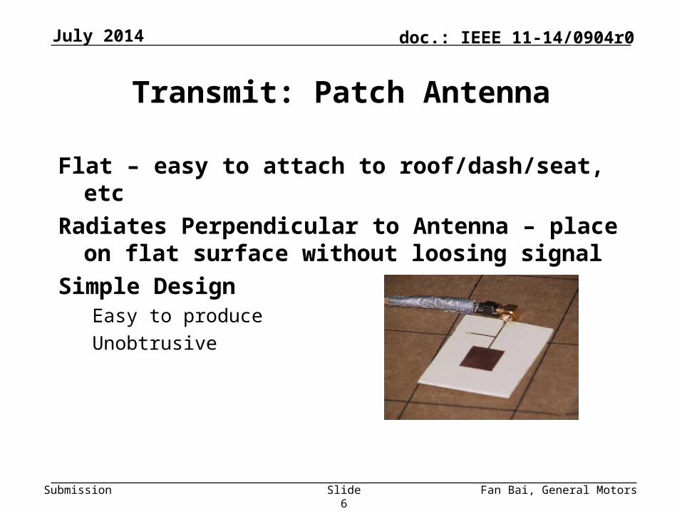
Transmit: Patch Antenna
Flat – easy to attach to roof/dash/seat, etc
Radiates Perpendicular to Antenna – place on flat surface without loosing signal
Simple DesignEasy to produce
Unobtrusive
July 2014
Slide 6

Submission
doc.: IEEE 11-14/0904r0
Fan Bai, General Motors
Receive: Dipole Antenna
Radial – Easy to capture single polarization
Vertical Design – ability to “probe” within the vehicle
Simple DesignEasy to Prototype
July 2014
Slide 7
Submission
doc.: IEEE 11-14/0904r0
Fan Bai, General Motors8
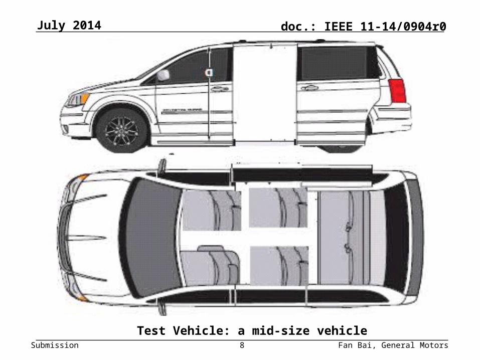
Test Vehicle: a mid-size vehicle
July 2014
Submission
doc.: IEEE 11-14/0904r0
Fan Bai, General Motors
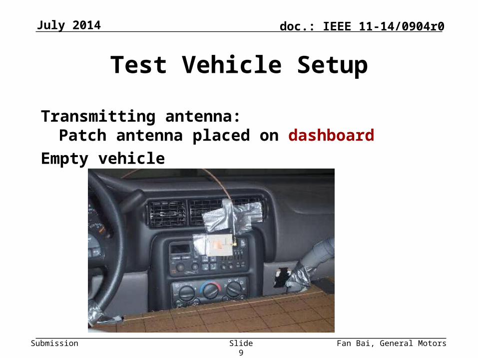
Test Vehicle Setup
Transmitting antenna: Patch antenna placed on dashboard
Empty vehicle
July 2014
Slide 9
Submission
doc.: IEEE 11-14/0904r0
Fan Bai, General Motors
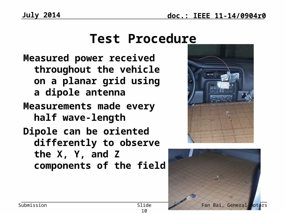
Test Procedure
Measured power received throughout the vehicle on a planar grid using a dipole antenna
Measurements made every half wave-length
Dipole can be oriented differently to observe the X, Y, and Z components of the field
July 2014
Slide 10

Submission
doc.: IEEE 11-14/0904r0
Fan Bai, General Motors
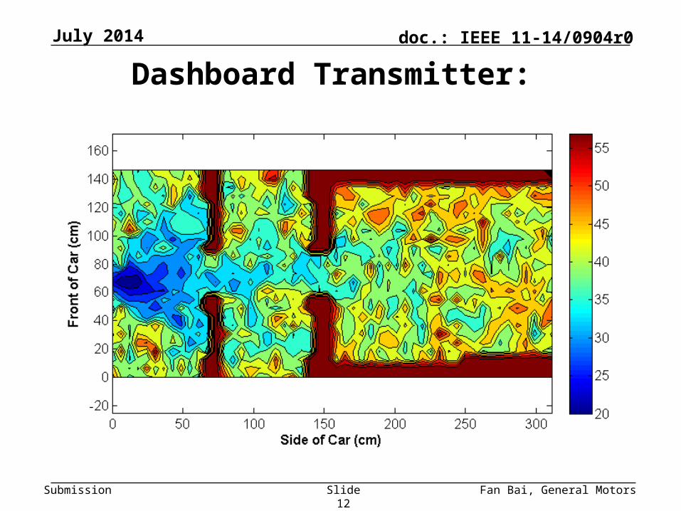
Dashboard Transmitter: Power loss (dB)
July 2014
Slide 11
Submission
doc.: IEEE 11-14/0904r0
Fan Bai, General Motors
Dashboard Transmitter:
July 2014
Slide 12

Submission
doc.: IEEE 11-14/0904r0
Fan Bai, General Motors
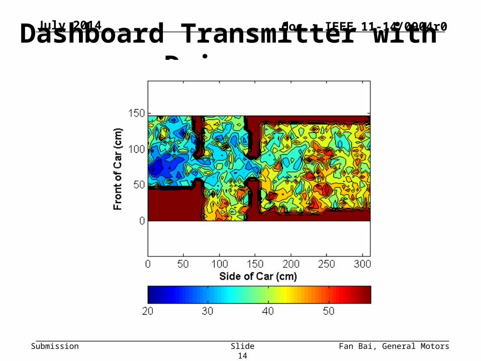
Dashboard Transmitter with Driver: Power loss (dB)
July 2014
Slide 13
Submission
doc.: IEEE 11-14/0904r0
Fan Bai, General Motors
Dashboard Transmitter with Driver: July 2014
Slide 14
Submission
doc.: IEEE 11-14/0904r0
Fan Bai, General Motors
This preliminary study considers
Dashboard transmitter
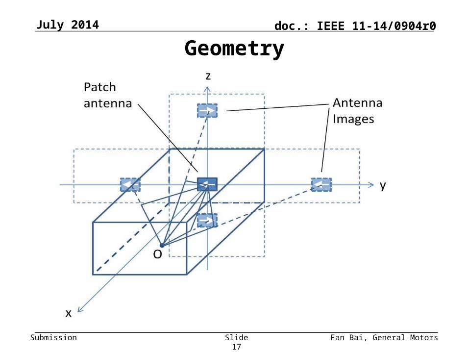
In-cabin geometry as a rectangular prism
Model the existence of dominant reflections for various in-cabin surfaces (up to 5 rays)
Image-based Ray-tracing methodSimplest model: angle independent antennas
More realistic: patch on dashboard with mobile dipole
July 2014
Slide 15

Submission
doc.: IEEE 11-14/0904r0
Fan Bai, General Motors
Representative Mid-Size Vehicle Example
A mid-size vehicle
July 2014
Slide 16
Submission
doc.: IEEE 11-14/0904r0
Fan Bai, General Motors
GeometryJuly 2014
Slide 17
Submission
doc.: IEEE 11-14/0904r0
Fan Bai, General Motors
Simplest Model: Angle-independent
Assume gains of both dash and mobile antennas do not depend on angleProduct of gains taken to be adjustable parameter
Keep signs of images, but otherwise take reflection coefficients to be adjustable parameters
Keep only specular reflections from sides, bottom, and top
Assume always polarization matched
July 2014
Slide 18
Submission
doc.: IEEE 11-14/0904r0
Fan Bai, General Motors
Simulation Example
The model is capable of generating the dB loss for any point in the cabin
Example: consider deploying receiving devices at 2.4 GHz on a 52 by 25 grid with half-wavelength separations. This results in 1300 (52 by 25) grid locations
Using the 1-ray(5-ray) model, we simulated the dB loss at these locations and generated a contour plot interpolated based on these simulated values
July 2014
Slide 19
Submission
doc.: IEEE 11-14/0904r0
Fan Bai, General Motors
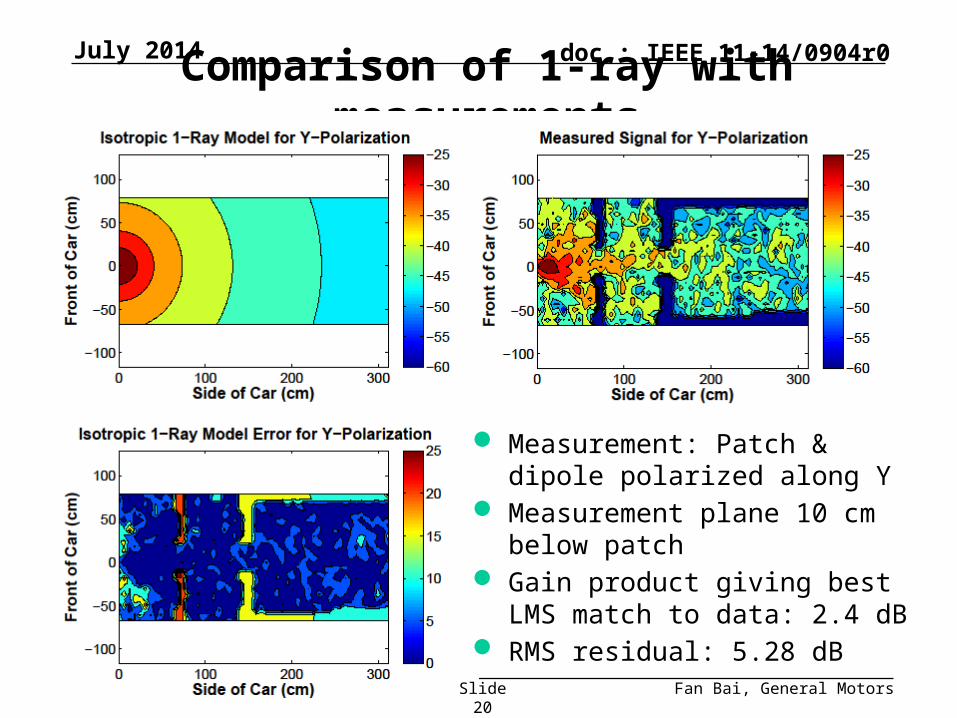
Comparison of 1-ray with measurements
Measurement: Patch & dipole polarized along Y
Measurement plane 10 cm below patch
Gain product giving best LMS match to data: 2.4 dB
RMS residual: 5.28 dB
July 2014
Slide 20

Submission
doc.: IEEE 11-14/0904r0
Fan Bai, General Motors
R=0.66RMS = 5.28 dB
RMS=5.26 dB
July 2014
Slide 21
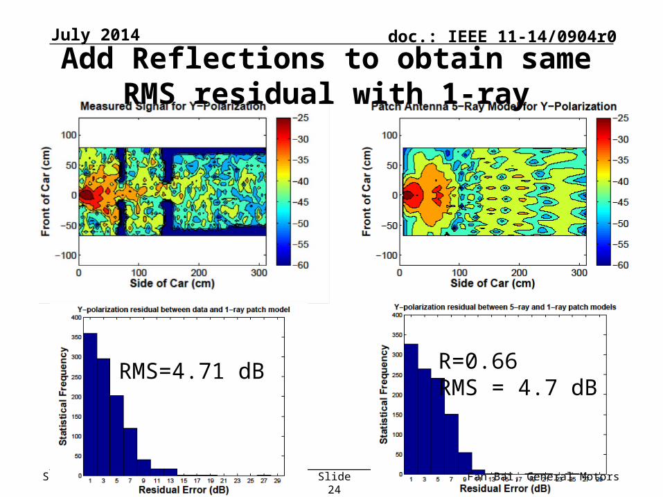
Add Reflections to obtain same RMS residual with 1-ray
Submission
doc.: IEEE 11-14/0904r0
Fan Bai, General Motors
More Realistic Model: Patch + Dipole
Use actual fields from Y-polarized patch on dashboard
Use vector effective length of dipole mobile antenna
As before use gain-product and reflection coefficients as adjustable parameters
Consider three orthogonal polarizations
July 2014
Slide 22

Submission
doc.: IEEE 11-14/0904r0
Fan Bai, General Motors
Comparison of 1-ray with measurements
Measurement: Patch & dipole polarized along Y
Measurement plane 10 cm below patch
Gain product giving best LMS match to data: -0.4 dB
RMS residual: 4.71 dB
July 2014
Slide 23
Submission
doc.: IEEE 11-14/0904r0
Fan Bai, General Motors
RMS=4.71 dB R=0.66RMS = 4.7 dB
July 2014
Slide 24
Add Reflections to obtain same RMS residual with 1-ray
Submission
doc.: IEEE 11-14/0904r0
Fan Bai, General Motors
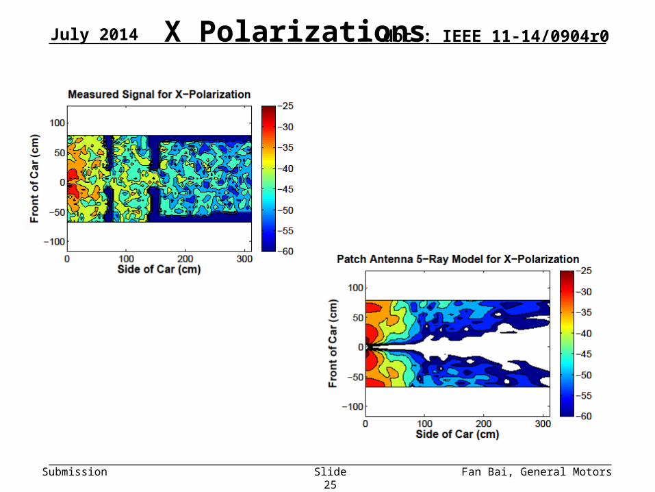
X PolarizationsJuly 2014
Slide 25
Submission
doc.: IEEE 11-14/0904r0
Fan Bai, General Motors
Summary and Conclusions
Despite the multipath in the cabin, 1-ray (direct path) models perform reasonably well for co-polarized component (RMS error ~ 5dB)
Crude model with angle-independent gain only about ½ dB worse RMS error than using actual fields from patch & dipole
Single specular reflections can be used to generate fluctuations with similar RMS values and distributions as those measured
Empirically, it appears depolarization from scattering dominates much of the region of interest for cross-polarized components, so specular-reflection models are less useful.
July 2014
Slide 26
Submission
doc.: IEEE 11-14/0904r0
Fan Bai, General Motors
References[1] M. Peter, R. Felbecker, W. Keusgen, J. Hillebrand "Measurement-based investigation of 60 GHz broadband
transmission for wireless in-car communication." Vehicular Technology Conference Fall (VTC 2009-Fall), 2009 IEEE 70th. IEEE, 2009.
[2] P. Smulders, "Exploiting the 60 GHz band for local wireless multimedia access: prospects and future directions, " Communications Magazine, IEEE, vol.40, no.1, pp. 140-147, 2002.
[3] M. Peter, W. Keusgen, and M. Schirrmacher, "Measurement and analysis of the 60 GHz in-vehicular broadband radio channel, " in Vehicular Technology Conference, 2007. VTC 2007-Fall. 2007 IEEE 66th, Sep.-Oct. 2007.
[4] P. Wertz, D. Zimmermann, FM Landstorfer, G. Wolfle, and R. Hoppe, "Hybrid ray optical models for the penetration of radio waves into enclosed spaces," in IEEE Vehicular Technology Conference, 2003, vol. 1, pp. 109-113.
[5] M. Heddebaut, V. Deniau, and K. Adouane, "In-vehicle WLAN radio- frequency communication characterization," Intelligent Transportation Systems, IEEE Transactions on, vol. 5, no. 2, pp. 114-121, 2004.
[6] O. Delangre, S. Van Roy, P. De Doncker, M. Lienard, and P. Degauque, "Modeling in-vehicle wideband wireless channels using reverberation chamber theory," IEEE Vehicular Technology Conference, pp. 2149-2153, 2007.
[7] F. Bellens, F. Quitin, F. Horlin, and P. De Doncker, "UWB channel analysis within a moving car, " The 9th International Conference on Intelligent Transport Systems Telecommunications (ITST), 2009. IEEE, pp. 681-684.
[8] Y. Katayama, K. Terasaka, K. Higashikaturagi, I. Matunami, and A. Kaji- wara, "Ultra-wideband impulse-radio propagation for in-vehicle wireless link," IEEE Vehicular Technology Conference, VTC-2006 Fall. 2006.
[9] Y. Nakahata, K. Ono, I. Matsunami, and A. Kajiwara, "Performance evaluation of vehicular ultra- wideband radio channels, " IEEE Vehicular Technology Conference, 2008. VTC 2008-Fall, pp. 1-5.
[10] J. Mar, Y.-R. Lin, and Y.-co Yeh, "Ultra-wide bandwidth in-vehicle channel measurements using chirp pulse sounding signal," IET Sci. Meas. Technol., vol. 3, iss. 4, pp.271-278, July 2009.
[11] T. Kobayashi, "Measurements and characterization of ultra wideband propagation channels in a passenger-car compartment," IEEE ISSTA 2006, pp.228-232, Aug. 2006.
[12] M. Schack, J. Jemai, R. Piesiewicz, R. Geise, I. Schmidt and T. Kurner, "Measurements and analysis of an in-car UWB channel," Proc. IEEE Vehicular Technology Conference 2008-Spring, pp.459-463, May 2008.
July 2014
Slide 27