submersible pumps drainage/sump seriesamtpumps.com/products/pdfmanuals/5980-251-00.pdf · 5983-95...
TRANSCRIPT
Specifications Information and Repair Parts Manual 5980-95 , 5981-95, 5983-95, 598A-95
5980-251-00 1 3/2018
Please read and save this Repair Parts Manual. Read this manual and the General Operating Instructions carefully before attempting to assemble, install, operate or maintain the product described. Protect yourself and others by observing all safety information. The Safety Instructions are contained in the General Operating Instructions. Failure to comply with the safety instructions accompanying this product could result in personal injury and/or property damage! Retain instructions for future reference. AMT reserves the right to discontinue any model or change specifications at any time without incurring any obligation.
©2018 AMT Pump Company, A Subsidiary of The Gorman-Rupp Company, All Rights Reserved.
Periodic maintenance and inspection is required on all pumps to ensure proper operation. Unit must be clear of debris and sediment. Inspect for leaks and loose bolts. Failure to do so voids warranty.
Submersible PumpsDrainage/Sump SeriesRefer to pump manual 1808-636-00 for General Operating and Safety Instructions.
MAINTENANCE
Make certain that unit is disconnected from power source before attempting to service or remove any component.
POWER CORD REPLACEMENTPeriodically inspect power cord and replace whenever abrasion, cracking, softening, or other signs of deterioration are found.
Refer to Figures 1 and 2.1. Place unit on workbench in upright position. Clean dirt and rust from
around wire cover (Ref. No. 4).2. Remove two fasteners (Ref. No. 2) which hold cord retainer (Ref. No. 1).3. Remove four fasteners (Ref. No. 8) which hold wire cover in place.4. Carefully pry cover from unit with screwdriver.IMPORTANT: Be careful to keep rust and other debris from falling into motor housing during cover removal.5. Take note of proper wire configuration, and connect new power cord (Ref.
No. 1) in identical fashion. If unsure about above information or wiring diagrams, consult an electrician familiar with motor wiring.
6. Clean sealing flanges if necessary and reassemble pump in reverse order.
IMPELLER INSPECTION / REPLACEMENT
If pump develops poor performance characteristics, impeller may be worn or clogged.
IMPELLER INSPECTIONRefer to Figure 2.1. Place unit on workbench in horizontal position and clean rust and buildup
from around pump-to-motor flange.2. Remove three fasteners (Ref. No. 42) to free screen (Ref. No. 41).3. Remove three fasteners (Ref. No. 40) and use screwdriver to pry base
(Ref. No. 39) from pump assembly.4. Inspect impeller (Ref. No. 37). If clog is found, remove debris and
reassemble in reverse order. If damage to impeller is found, such as pitting, deep grooves, or breakage, proceed to next section.
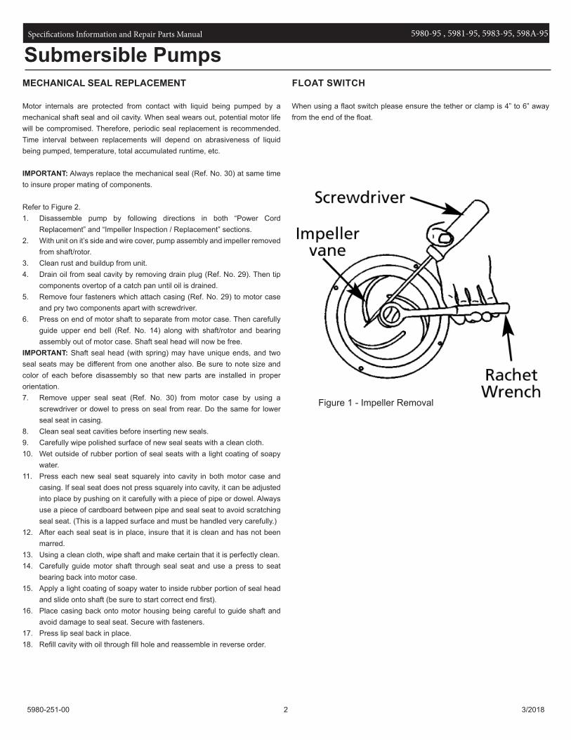
IMPELLER REPLACEMENT1. Remove impeller fastener (Ref. No. 38) by unscrewing in counterclockwise
direction.NOTE: To prevent motor shaft from turning, wedge a screwdriver between impeller vane and impeller fastener (see Figure 1).2. Unthread the impeller from the motor shaft/rotor (Ref. No. 24).3. Install replacement impeller and reassemble in reverse order.
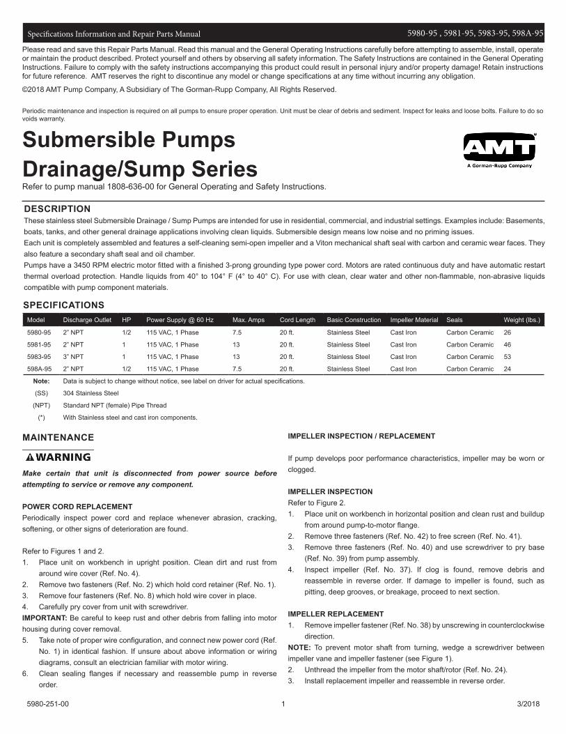
DESCRIPTIONThese stainless steel Submersible Drainage / Sump Pumps are intended for use in residential, commercial, and industrial settings. Examples include: Basements, boats, tanks, and other general drainage applications involving clean liquids. Submersible design means low noise and no priming issues.Each unit is completely assembled and features a self-cleaning semi-open impeller and a Viton mechanical shaft seal with carbon and ceramic wear faces. They also feature a secondary shaft seal and oil chamber.Pumps have a 3450 RPM electric motor fitted with a finished 3-prong grounding type power cord. Motors are rated continuous duty and have automatic restart thermal overload protection. Handle liquids from 40° to 104° F (4° to 40° C). For use with clean, clear water and other non-flammable, non-abrasive liquids compatible with pump component materials.
Model Discharge Outlet HP Power Supply @ 60 Hz Max. Amps Cord Length Basic Construction Impeller Material Seals Weight (lbs.)
5980-95 2” NPT 1/2 115 VAC, 1 Phase 7.5 20 ft. Stainless Steel Cast Iron Carbon Ceramic 26
5981-95 2” NPT 1 115 VAC, 1 Phase 13 20 ft. Stainless Steel Cast Iron Carbon Ceramic 46
5983-95 3” NPT 1 115 VAC, 1 Phase 13 20 ft. Stainless Steel Cast Iron Carbon Ceramic 53
598A-95 2” NPT 1/2 115 VAC, 1 Phase 7.5 20 ft. Stainless Steel Cast Iron Carbon Ceramic 24
Note: Data is subject to change without notice, see label on driver for actual specifications.
(SS) 304 Stainless Steel
(NPT) Standard NPT (female) Pipe Thread
(*) With Stainless steel and cast iron components.
SPECIFICATIONS
Specifications Information and Repair Parts Manual 5980-95 , 5981-95, 5983-95, 598A-95
5980-251-00 2 3/2018
MECHANICAL SEAL REPLACEMENT
Motor internals are protected from contact with liquid being pumped by a mechanical shaft seal and oil cavity. When seal wears out, potential motor life will be compromised. Therefore, periodic seal replacement is recommended. Time interval between replacements will depend on abrasiveness of liquid being pumped, temperature, total accumulated runtime, etc.
IMPORTANT: Always replace the mechanical seal (Ref. No. 30) at same time to insure proper mating of components.
Refer to Figure 2.1. Disassemble pump by following directions in both “Power Cord
Replacement” and “Impeller Inspection / Replacement” sections.2. With unit on it’s side and wire cover, pump assembly and impeller removed
from shaft/rotor.3. Clean rust and buildup from unit.4. Drain oil from seal cavity by removing drain plug (Ref. No. 29). Then tip
components overtop of a catch pan until oil is drained.5. Remove four fasteners which attach casing (Ref. No. 29) to motor case
and pry two components apart with screwdriver.6. Press on end of motor shaft to separate from motor case. Then carefully
guide upper end bell (Ref. No. 14) along with shaft/rotor and bearing assembly out of motor case. Shaft seal head will now be free.
IMPORTANT: Shaft seal head (with spring) may have unique ends, and two seal seats may be different from one another also. Be sure to note size and color of each before disassembly so that new parts are installed in proper orientation.7. Remove upper seal seat (Ref. No. 30) from motor case by using a
screwdriver or dowel to press on seal from rear. Do the same for lower seal seat in casing.
8. Clean seal seat cavities before inserting new seals.9. Carefully wipe polished surface of new seal seats with a clean cloth.10. Wet outside of rubber portion of seal seats with a light coating of soapy
water.11. Press each new seal seat squarely into cavity in both motor case and
casing. If seal seat does not press squarely into cavity, it can be adjusted into place by pushing on it carefully with a piece of pipe or dowel. Always use a piece of cardboard between pipe and seal seat to avoid scratching seal seat. (This is a lapped surface and must be handled very carefully.)
12. After each seal seat is in place, insure that it is clean and has not been marred.
13. Using a clean cloth, wipe shaft and make certain that it is perfectly clean.14. Carefully guide motor shaft through seal seat and use a press to seat
bearing back into motor case.15. Apply a light coating of soapy water to inside rubber portion of seal head
and slide onto shaft (be sure to start correct end first).16. Place casing back onto motor housing being careful to guide shaft and
avoid damage to seal seat. Secure with fasteners.17. Press lip seal back in place.18. Refill cavity with oil through fill hole and reassemble in reverse order.
FLOAT SWITCH
When using a flaot switch please ensure the tether or clamp is 4” to 6” away from the end of the float.
Submersible Pumps
Figure 1 - Impeller Removal
Specifications Information and Repair Parts Manual 5980-95 , 5981-95, 5983-95, 598A-95
5980-251-00 3 3/2018
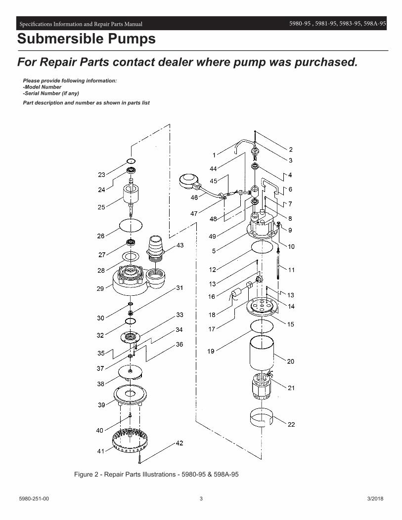
For Repair Parts contact dealer where pump was purchased.Please provide following information:-Model Number-Serial Number (if any)
Part description and number as shown in parts list
Figure 2 - Repair Parts Illustrations - 5980-95 & 598A-95
Submersible Pumps

Specifications Information and Repair Parts Manual 5980-95 , 5981-95, 5983-95, 598A-95
5980-251-00 4 3/2018
Ref Part Number for Models
No. Description 5980-95 598A-95 Qty
1 Power Cord Kit 5980-350-90 598A-350-90 1
(includes Ref. Nos. 1, 2, 3 and 4)
2 Fastener Incl. w/Ref. 1 Incl. w/Ref. 1 1
3 O-Ring Incl. w/Ref. 1 Incl. w/Ref. 1 1
4 O-Ring/Gasket Incl. w/Ref. 1 Incl. w/Ref. 1 1
5 Wire Cover Replace Pump Replace Pump 1
6 Handle Kit 5980-100-90 598A-100-90 1
7 Fastener * * 1
8 Seal Incl. w/Ref. 50 Incl. w/Ref. 50 1
9 Fastener * * 4
10 Seal Incl. w/Ref. 50 Incl. w/Ref. 50 4
11 Fastener - - 4
12 O-Ring Incl. w/Ref. 50 Incl. w/Ref. 50 1
13 Fastener * * 2
14 Seal Incl. w/Ref. 50 Incl. w/Ref. 50 2
15 Upper Bracket Replace Pump Replace Pump 1
16 Retainer N/A N/A 1
17 Insulation Paper N/A N/A 1
18 Capacitor N/A N/A 1
19 O-Ring Incl. w/Ref. 50 Incl. w/Ref. 50 1
20 Motor Casing Replace Pump Replace Pump 1
21 Coil & Stator Replace Pump Replace Pump 1
22 Spacer N/A N/A 1
23 Waved Washer N/A N/A 1
24 Bearing Replace Pump Replace Pump 1
25 Shaft & Rotor Replace Pump Replace Pump 1
26 O-Ring Incl. w/Ref. 50 Incl. w/Ref. 50 1
27 Bearing Replace Pump Replace Pump 1
28 Insulation Paper N/A N/A 1
29 Pump Casing 5980-001-90 598A-001-90 1
30 & 31 Mechanical Seal Incl. w/Ref. 50 Incl. w/Ref. 50 1
32 O-Ring Incl. w/Ref. 50 Incl. w/Ref. 50 1
33 Seal Plate 5980-020-90 598A-020-90 1
(includes Ref. Nos. 33 and 34)
34 Fastener Incl. w/Ref. 33 Incl. w/Ref. 33 4
35 Seal Incl. w/Ref. 50 Incl. w/Ref. 50 4
36 Fastener * * 4
37 Slinger Washer * * 1
38 Impeller 5980-010-90 598A-010-90 1
39 Suction Cover 5980-050-90 598A-050-90 1
(includes Ref. Nos. 39 and 40)
40 Fastener Incl. w/Ref. 39 Incl. w/Ref. 39 1
41 Suction Screen 5980-040-90 598A-040-90 1
(includes Ref. Nos. 41 and 42)
42 Fastener Incl. w/Ref. 41 Incl. w/Ref. 41 1
Repair Parts List

Specifications Information and Repair Parts Manual 5980-95 , 5981-95, 5983-95, 598A-95
5980-251-00 5 3/2018
Ref Part Number for Models
No. Description 5980-95 598A-95 Qty
43 Hose Coupling 5980-170-90 598A-170-90
44 Outlet Rubber - Incl. w/Ref. 46 1
45 Cable Protection - Incl. w/Ref. 46 1
46 Float Switch Kit - 598A-351-90 1
47 Wire Loom - Incl. w/Ref. 46 1
48 Gasket - Incl. w/Ref. 46 1
49 Float Junction - Incl. w/Ref. 46 1
50 Seal Kit (not shown) 5980-300-90 598A-300-90 1
(includes Ref. Nos. 8, 10, 12, 14, 19, 26, 30, 31, 32 and 35)
(-) Not Available
(*) Standard hardware item, available locally.
Repair Parts List - CONTINUED

Specifications Information and Repair Parts Manual 5980-95 , 5981-95, 5983-95, 598A-95
5980-251-00 6 3/2018
For Repair Parts contact dealer where pump was purchased.Please provide following information:-Model Number-Serial Number (if any)
Part description and number as shown in parts list
Figure 3 - Repair Parts Illustrations - 5981-95 & 5983-95
Submersible Pumps

Specifications Information and Repair Parts Manual 5980-95 , 5981-95, 5983-95, 598A-95
5980-251-00 7 3/2018
Ref Part Number for Models
No. Description 5981-95 5983-95 Qty
1 Cable Protection Incl. w/Ref. 4 Incl. w/Ref. 4 1
2 Retainer Incl. w/Ref. 4 Incl. w/Ref. 4 1
3 Fastener Incl. w/Ref. 4 Incl. w/Ref. 4 1
4 Power Cord Kit 5981-350-90 5983-350-90 1
(includes Ref. Nos. 1, 2, 3, 4 and 5) 1
5 O-ring Incl. w/Ref. 4 Incl. w/Ref. 4 1
6 Wire Cover Replace Pump Replace Pump 1
7 Fastener * * 4
8 Seal Incl. w/Ref. KIT Incl. w/Ref. KIT 1
9 Handle Kit 5981-101-90 5981-101-90 1
10 Fastener * * 2
11 Fastener * * 1
12 Seal Incl. w/Ref. KIT Incl. w/Ref. KIT 1
13 Fastener * * 4
14 Seal Incl. w/Ref. KIT Incl. w/Ref. KIT 4
15 Retainer N/A N/A 1
16 Insulation Paper N/A N/A 1
17 Capacitor N/A N/A 1
18 Capacitor N/A N/A 1
19 Retainer N/A N/A 1
20 Insulation Paper N/A N/A 1
21 Capacitor Base Replace Pump Replace Pump 1
22 Fastener * * 1
23 Fastener * * 1
24 Switch Replace Pump Replace Pump 1
25 Fastener * * 4
26 Fixed Point N/A N/A 1
27 Upper Bracket Replace Pump Replace Pump 1
28 Insulation Paper N/A N/A 1
29 O-Ring Incl. w/Ref. KIT Incl. w/Ref. KIT 1
30 Motor Casing Replace Pump Replace Pump 1
31 Stator Replace Pump Replace Pump 1
32 Spacer Replace Pump Replace Pump 1
33 Waved Washer N/A N/A 1
34 Bearing Replace Pump Replace Pump 4
35 Shaft & Rotor Replace Pump Replace Pump 1
36 Key Replace Pump Replace Pump 1
Repair Parts List

Specifications Information and Repair Parts Manual 5980-95 , 5981-95, 5983-95, 598A-95
5980-251-00 8 3/2018
Ref Part Number for Models
No. Description 5981-95 5983-95 Qty
37 O-Ring Incl. w/Ref. KIT Incl. w/Ref. KIT 1
38 O-Ring Incl. w/Ref. KIT Incl. w/Ref. KIT 1
39 Bearing Replace Pump Replace Pump 1
40 Motor Lower Cover Replace Pump Replace Pump 1
41 Fastener * * 4
42 Seal Incl. w/Ref. KIT Incl. w/Ref. KIT 4
43 Mechanical Seal Incl. w/Ref. KIT Incl. w/Ref. KIT 1
44 O-Ring Incl. w/Ref. KIT Incl. w/Ref. KIT 1
45 Seal Plate 5981-021-90 5981-021-90 1
(includes Ref. Nos. 45 and 46)
46 Fastener Incl. w/Ref. 45 Incl. w/Ref. 45 4
47 Seal Incl. w/Ref. KIT Incl. w/Ref. KIT 1
48 Fastener * * 1
49 Protector N/A N/A 1
50 Impeller 5981-010-90 5983-011-90 1
(includes Ref. Nos. 50 and 52)
51 Impeller Seal Incl. w/Ref. KIT Incl. w/Ref. KIT 1
52 Impeller Nut Incl. w/Ref. 50 Incl. w/Ref. 50 1
53 Pump Casing 5981-002-90 5983-002-90 1
54 Strainer N/A 5983-050-90 1
(includes Ref. Nos. 54 and 55)
55 Fastener N/A Incl. w/Ref. 54 4
56 Gasket Incl. w/Ref. KIT Incl. w/Ref. KIT 1
57 NPT Flange 5981-170-90 5983-170-90 1
(includes Ref. Nos. 57 and 58)
58 Screw Incl. w/Ref. 57 Incl. w/Ref. 57 1
59 Fastener * * 3
60 Plate Replace Pump Replace Pump 1
61 Sleeve N/A N/A 1
62 Seal Incl. w/Ref. KIT Incl. w/Ref. KIT 1
KIT Seal Kit 5891-301-90 5983-301-90 1
(includes Ref. Nos. 8, 12, 14, 29, 36, 38, 42, 43, 44, 47, 51, 56 and 62)
(-) Not Available
(*) Standard hardware item, available locally.
Repair Parts List - CONTINUED

Specifications Information and Repair Parts Manual 5980-95 , 5981-95, 5983-95, 598A-95
5980-251-00 9 3/2018
NOTES:

Specifications Information and Repair Parts Manual 5980-95 , 5981-95, 5983-95, 598A-95
5980-251-00 10 3/2018
NOTES:


www.amtpump.com