submerged arc welding ferritic steels with alloyed metal powder
TRANSCRIPT

WELDING RESEARCH
SUPPLEMENT TO THE WELDING JOURNAL, AUGUST 1991
Sponsored by the American Welding Society and the Welding Research Council
All papers published in the Welding Journal's Welding Research Supplement undergo Peer Review before publication for: 1) originality of the contribution; 2) technical value to the welding community; 3) prior publication of the material being reviewed; 4) proper credit to others working in the same area; and 5) justification of the conclusions, based on the work performed.
The names of the more than 170 individuals serving on the AWS Peer Review Panel are published periodically. All are experts in specific technical areas, and all are volunteers in the program.
Submerged Arc Welding Ferritic Steels with Alloyed Metal Powder
Metal powder additions increased efficiency, reduced weld passes and did not impair toughness
BY N. BAILEY
ABSTRACT. The overall objective of this project was to provide data showing how metal powder additions to submerged arc welds can be used safely to give increased productivity and hence reduce fabrication costs. In general, the aims of the program were to improve the balance between properties and productivity, either by improving heat-affected zone (HAZ) and
KEY W O R D S
SAW Ferritic Steels Alloyed Metal Powder Deposition Rates Heat Inputs Multipass Welds Weld Metal Toughness Triple Arc Welding HAZ Toughness Structural Steel
N. BAILEY is with the Materials Department, The Welding Institute, Abington, Cambridge, England.
Paper presented at the 72nd Annual AWS Meeting, held April 14-19, 1991, in Detroit, Mich.
weld metal toughness levels while increasing productivity or, at least, to improve productivity without impairing toughness. In the case of multiwire single- and two-pass welds, the major objective was to increase the material thickness that can be welded while maintaining good toughness, as assessed by Charpy testing. Where multipass welding must be used, the aim was to improve either productivity or toughness as alternative goals.
Introduction
The addition of metal (or iron) powders has long been known (Refs. 1-9) as a means of improving the productivity of submerged arc welding, as it allows the heat from the arc to melt additional quantities of filler metal, rather than wastefully
melt unnecessary amounts of base plate. When first introduced, metal powders tended to be used merely to improve productivity, but the ability to increase metal deposition without increasing heat input allows the possibility of using powders for high-quality welding, where heat input must be controlled to maintain toughness levels, while still maintaining reasonably high joint completion rates.
Two obvious ways of using metal powders in high-quality welding are to increase deposition rates when the heat input is limited and to reduce the heat input required when making one- and two-pass welds in relatively thick plate. A third possibility is to use specially formulated metal powders to make alloying additions into the weld pool to achieve desirable compositions.
Table 1—
Thickness mm (in.)
30(1.2) 40 (1.6) 75(3)
Analyses of Test Plates'"'
C
0.17 0.10 0.13
S
0.009 0.006 0.004
P
0.019 0.016 0.012
Element (wt-
Si
0.41 0.36 0.32
Mn
1.29 1.53 1.44
%)
Ni
0.03 0.14 0.07
Cr
0.03 0.02 0.09
Cu
0.01 0.15 0.19
N
0.004 0.004 0.011
CE<b>
0.39 0.38 0.41
(a) All samples contained 0,03-0.04ooAl and Nb, <0.005°0Sn, <0.01%Mo, Co, <0.002%V, Ti, <0.0003%B, 0.001%0.
M n Cr -(b) CE: carbon equivalent, CE + C + —— +
WELDING RESEARCH SUPPLEMENT 1187-s

In the pro jec t descr ibed b e l o w , all three possibilities w e r e examined, using either tw in or tr iple arc systems, as the French Institut de Soudure was carrying ou t a parallel p rog ram using single w i re we ld ing (Ref. 10).
W o r k i n g P r o g r a m
A C-Mn-Nb steel of 350 N / m m 2 (51 ksi) m in imum yield strength to BS4360 Grade 50E was used th roughou t — Table 1. The test p rog ram was d iv ided into three phases: single-pass, two-pass and mult i pass weld ing.
Single-Pass, Triple-Arc Welding
A 30 m m (1.2 in.) thickness o f steel was selected as being the thickest likely to be we lded in a single pass w i t h reasonable toughness. Procedures w e r e deve loped fo r triple-arc we ld ing (Table 2), using an S3 (1.5% Mn) we ld ing w i re (Table 3) w i t h a p o w d e r al loyed w i th M o , Ti and B (Table 4) to improve w e l d metal toughness and a fully basic flux, Oer l i kon OP121TT. 1 The powde rs for the single- and also the t w o -pass welds w e r e specially fo rmula ted to give the requi red w e l d metal compos i tions for the consumables and type of we ld ing being used.
Table 2—Plan of Single-Pass Welds
Weld No. Purpose
W l Comparison, no metal powder, aimed to fill joint.
W2 Metal powder, faster speed than W l .
W3 Comparison, no metal powder, welding as W2.
W4 Metal powder, as W2, but ceramic backing.
W5 Comparison, no metal powder, as W3 to provide cooling data.
T w o welds (Table 2) w e r e made w i t h this p o w d e r , one (W2) w i t h a steel backing bar, the other (W4) w i t h ceramic backing. For compar ison, three welds we re made using S3 we ld ing w i re w i thou t p o w d e r addit ions. In one of these (W1) the we ld ing g roove was fil led complete ly ; the other (W3) was depos i ted using the same we ld ing parameters as W 2 but leaving the g roove incompletely fi l led. W e l d W 5 was made w i t hou t p o w d e r addit ions, t o measure cool ing data wh i ch had no t been obta ined in the earlier welds.
Two-Pass, Triple-Arc Welding
The plate selected was o f 40 m m (1.6 in.) thickness and the two-pass, doub le-V, triple-arc welds w e r e made w i th a gas metal arc (GMA) tacking pass and w i t h a less basic flux (OP122) than fo r the single-pass welds, but wh i ch was designed for two-pass we ld ing . The plan of the welds is g iven in Table 5. The compar ison we lds w i thou t metal p o w d e r w e r e made w i t h one Mo-Cr-Ti -B co red w i re 2 and t w o 0.5% M n solid wires (Table 3). The test welds w i t h p o w d e r included t w o Mo-T i -B composi t ions (Table 4), fo r one of wh i ch (W14) all the M o , Ti and B was added f r o m the p o w d e r (described as the rich p o w der) using simple 1.5% M n solid we ld ing wires, and for the other (W13) these elements w e r e added f r o m solid wires, as
(1) It should be noted that the flux was used above the maximum current recommended by the manufacturer.
(2) As with the solid wires, the analysis on this cored wire was carried out by a direct reading spectrograph technique on a button prepared by melting samples of the wire on a water-cooled copper hearth with a tungsten arc in an inert atmosphere. Although this technique is reliable for solid wires, it is inevitably approximate for flux-cored wires.
wel l as f r o m a p o w d e r leaner in M o , Ti and B. The final compar ison (we ld W 1 2 , M n -M o ) was made to assess whe the r the reduct ion in heat input possible w i t h the metal p o w d e r w o u l d be sufficient to give adequate w e l d metal toughness p roper ties w i t hou t the use of the al loying addi tions Ti and B.
Multipass, Twin Arc Welding
Mult ipass welds w e r e made on 75 -mm (3-in.) thick steel using tw in 4 -mm (5/32-in.) diameter 1.5% M n (S3) wires and the basic flux (OP121TT) used fo r the single pass welds. As we l l as the matching 1.5% M n p o w d e r (Table 4), a p o w d e r containing 1.5% M n , 1 % Ni, 0.5% M o was used w i t h a 1.5% M n w i re in an a t tempt to achieve a bet ter combina t ion o f strength and toughness, b o t h as-welded and in the pos twe ld heat t reated (PWHT) cond i t ion , than can be obta ined w i t h the standard 1.5% M n compos i t ion . Both p o w d e r s w e r e standard, commerc ia l a tomized products .
The plan (Table 6) shows t w o compar ison welds , one w i th the same heat input as the metal p o w d e r we lds , 3 k j / m m (76 k j / in . ) , and the other w i t h a higher heat input o f 5.5 k j / m m (140 k j / in . ) , wh i ch requi red a smaller number o f passes.
The composi t ions of the wires and p o w d e r s used are included in Tables 3 and 6. A por t i on o f each w e l d was tested as-w e l d e d , the other after heat t reatment fo r 3 h at 600°C(1110°F ) .
Welding Equipment
For all the mult iarc we ld ing , the direct current , e lect rode posit ive (DCEP) leading arc was p rov ided by an ESAB A6 head and cont ro l system and p o w e r e d by an ESAB LAD 1400 we ld ing rectif ier. The trailing alternat ing current (AC) arc(s) w e r e also p rov ided using ESAB A6 heads and cont ro l
Table 3—Compositions of Welding Wire Consumables'3'
Wire Type
Mo-Cr-Ti-B<b> Si (0.5Mn)
Weld for Identity which Used
Element wt-%
Mn Cr Mo Cu Al
2679 2680
W15 0.11 0.008 0.008 0.06 0.011 0.008
0.36 <0.01
-2.3 0.72 0.54 0.07 0.14 0.027 - 0 . 0 2 0.50 <0.005 <0.005 0.01 <0.002 0.004 <0.0003
O
-0.33 0.019
-0.01 0.003
S3 (1.5Mn) 2675A
2677 2691(C> 2693
W15, W9, 16-19
W1-5 W18, 19 W19
14, 0.09 0.016 0.008 0.24 1.64 0.04 0.01 0.24 <0.002 0.006 <0.0003 0.006 0.008
0.12 0.10 0.11
0.014 0.011 0.010
0.008 0.013 0.013
0.31 0.34 0.26
1.53 1.75 1.72
0.05 0.04 0.09
0.01 0.04 0.02
0.17 0.08 0.22
<0.002 NA
<0.002
0.012 0.001 0.014
<0.0003 NA 0.0005
(a) All wires 4-mm diameter and contained also 0.02-0.05Ni, <0.002V (except 2679, 0.02%), £0.003Nb, s0.04Sn, sO.OlCo. (b) Cored wired, analyses for some elements are approximate. 0 used for second side only. (c) Supplier's analysis, NA —not analyzed.
0.003 NA 0.009
0.009 NA 0.008
S3-Mo
Mo-Ti-B
2684A 2684B 2689
2690A 2690B 2690C
W7, 12
W8, 13
0.11 0.12 0.10
0.11 0.11 0.11
0.011 0.012 0.013
0.006 0.006 0.007
0.009 0.009 0.008
0.014 0.014 0.014
0.22 0.22 0.23
0.06 0.06 0.06
1.52 1.51 1.49
1.12 1.11 1.12
0.05 0.05 0.04
0.03 0.03 0.03
0.49 0.50 0.54
0.32 0.32 0.32
0.13 0.13 0.13
0.13 0.13 0.14
<0.002 <0.002 <0.002
0.058 0.058 0.059
0.014 0.006 0.013
0.037 0.036 0.037
<0.0003 <0.0003 <0.0003
0.0032 0.0034 0.0034
0.006 0.004 0.005
0.003 0.003 0.005
0.008 0.008 0.009
0.005 0.006 0.006
188-s I AUGUST 1991

systems, and powered by two OTC KRUMSC 1500 drooping characteristic transformers in star connection.
The welding heads and reels of wire were mounted on a tractor carried on a gantry above the welding table. For ease of operation, metal powder was prelaid in the joint preparation using a Tapco bulk welding system. Current and voltage were monitored using moving coil chart recorders.
For each weld, the amount of metal powder deposited was calculated by subtracting from the weight of deposited metal the weight of wire used. This was determined from the length measured by a hand-held wire feed speed meter accurate to ± 100 mm/min (4 in./min).
Single Pass Welds
Procedure Development
A procedure was first established for welding 30-mm-thick plate in one pass without the use of metal powder. The procedure was then used for welding with a powder addition, the speed being increased to compensate for the increased rate of filler metal addition.
When developing procedures, the following principles were followed:
1) A high current DCEP leading arc was used to provide the high penetration required to melt through the metal powder,
2) A higher voltage was used with center and trailing arcs to achieve a good bead shape,
3) The preparation cross-section area was kept as small as practicable while allowing good root fusion and minimizing the risk of cracking due to the increasing depth/width ratio.
A single-V weld in a butt joint with a 5-mm (0.2-in.) root opening, no root face, and with a 20-deg included angle could be welded using an acceptable travel speed.
When welding without metal powder, a heavy backing bar was required to prevent melt through. With metal powder, the addition buffered the arc, reduced the penetration and hindered root fusion to such an extent that unfused powder was found in the root of the weld. This problem was overcome by reducing the powder addition from 17 to ~ 14.5 kg/h (37 to 32 Ib/h) and the thickness of the backing bar from 30 to 12.5 mm (1.2 to 0.5 in.).
Tests with ceramic backings showed that, although designed for welding with a maximum current of 500 A during normal submerged arc welding, they could be used at higher currents when welding with metal powder additions, and their use enabled powder consumption to be restored to 17.5 kg/h.
The welding procedures finally developed are given in Table 7, from which it can be seen that the use of metal powder additions allowed an increase in welding
Table A—Compositions of Metal Powders'3'
Type
Mo-Ti-B<b>
lean Mo-Ti-B<b>
rich Mo-Ti-B<b>
Mn-Mo<b>
Mn Mn-Ni-Mo
(a) Compositions (b) Aim composi (c) —not stated.
Type of Weld for
which Used
1 pass
2 pass
2 pass
2 pass
multipass multipass
as stated by ion given.
Method of
Manufacture C
agglomer- — ated
agglomer- -ated
agglomer- -ated
agglomer- -ated
atomized 0.13 atomized 0.13
manufacturers.
Table 5—Plan of Two-Pass Welds*"'
Weld No.
W15 W13
W14
W12
Welding wires
S
-
—
—
0.015 0.006
2 X 0.5 Mn + Mo-Cr-Ti-B<b> 3 X Mo-Ti-B
3 X 1.5Mn
3 X 1.5 Mn-Mo
Composition
P Si
- 0.2
- 0.2
- 0.2
0.015 0.43 0.011 0.46
Mn
1.3
1,3
1.6
1.81 1.45
Metal powder
None lean Mo-Ti-B
rich Mo-Ti-B
Mn-Mo
(wt-%)
Ni Mo Ti B
- 1.4 0.21 0.007
- 0.8 0.15 0.015
- 1.6 0.3 0.03
- 0.5 -
_ _ _ _ 1.03 0.54 -
Purpose
base line alloying equally from
and powder
Bulk Density g/mL.
2.58
2.54
2.48
2.55
3.64 3.42
wire
as W13 but all Mo-Ti-B powder
best likely toughness without Ti-B
(a) All welds triple arc using basic flux OP122 dried at 400°C (W15) or 450°C (W12-14) (750° and 840°F) (b) Flux cored wire.
Table 6—Plan of Multipass Welds<a>
Heat Input of Fill Passes, Weld No. Wire Type Metal Powder k j /mm (kj/in.)
W16 W19
W17
W18
S3 (1.5M S3
S3
S3
i) none none
1.5Mn
Mn-Ni-Mo
3
5.5
3
3
(76) (140)
(76)
(76)
Purpose
Base line Same bead size
as metal powder welds Comparison at same
heat input as W16 Higher alloying
(a) All welds made using twin arc and fully basic flux OP121TT on 75-mm (3-in.) thick plate using a double-V preparation. Sections of each weld heat treated for 3 h at 600° ± 10°C.
Table 7—Summary of Welding Parameters for Single-Pass Welds(a>
Weld No. W1 W2 W3 W4
Total current A* ' Travel speed, mm/min (in./min) Arc energy, k)/mm (kj/in.) Total deposition rate, kg/h (Ib/h) Powder deposition rate, kg/h (Ib/h)
2950 400 (15.7) 19.6 (500) 68.6 (151)
—
3050 550 (21.6) 14.7 (373) 94.3 (207) 14.5 (32)
3000 550 (21.6) 14.4 (366) 81.6(180)
—
2950 550(21.6) 13.8 (350) 72.2 (159) 17.5 (38.5)
(a) Single-V, 20 deg included angle, 5-mm (0.2-in.) root opening, steel or ceramic backing; triple arc, DCEP (vertical), AC 10 deg, AC 20 deg; wire, 1.5% Mn, powder (where used) Mn-Mo-Ti-B.. No preheat, flux dried 250°C (480°F), powder as received. (b) mean for DC, rms for AC.
speed from 400 to 550 mm/min (16 to 22 in/min), with a corresponding decrease in arc energy from 19.6 to 14.7 k j /mm (500 to 370 kj/in.). Comparison with the base line weld, W 1 , showed increases in deposition rate of 30 to 35% with the metal powder additions.
Thermal Cycle Measurements
An Intercole Systems Compulog IV data logging system was used to monitor the weld thermal cycle but the slag was too thick to be penetrated by the thermocouples, and satisfactory weld metal results
WELDING RESEARCH SUPPLEMENT 1189-s

W2
w;
I i
Fig. 1 - Macrosections of single pass welds in 30 mm (1.2 in.) plate. A - Wl, no metal powder, note small solidification crack near root: B — W2, metal powder addition, note low penetration into backing bar: C—W3, no metal powder, welding conditions as W2, note narrow weld shape: D — W4, as W2 with ceramic backing.
*jf , i J " w * * Wt • ?• ? \ i >* \ » ' ' ^ j | t ^ * * * ' %-**^^ " ' . -
*«• J * !« , . * ' * - • -v ° Sl_ "* • • > ^ . „v,V"*" ^ »'.••••:• ..r" ^ J V , ' ' * *Hfe : . ^ ; ' v-< ' v' ~ > c - _ \ ^-f" --..^A *. :;•;[•,< •;
N - > fc > j
_^' *"^ -_v '* - "T* v
A : - Lt I ' I ^—- J I , sj , « • • . y
2 -V...-; .< :!?:^- , ' ^ i ti
. - •M ~7"s-f F ~^~
' /"-V v-'V % . - l - V » ' . ' , . ^ - ' -*'**'• *.».>> " •<; *-**• yJS- j.- " •- "/•-
r **> *i' z 1 > .'
Fig. 2 —Single pass weld metal microstructures, X320. A — Wl, no metal powder: B— W2, metal powder addition: C- W4, metal powder addition, ceramic backing.
190-s | AUGUST 1991

were not obtained. It was, therefore, decided to sample the cooling of the HAZ in the other welds. On W4, melt through near the thermocouples prevented valid data from being obtained. With weld W5, thermal cycle measurements on the fusion line and in the HAZ were obtained, the 800° to 500°C cooling time for fusion line being 111 s.
Weld Macrostructures
The weld macrostructures are shown in Fig. 1. Weld W l , without powder additions, penetrated almost 5 mm (0.2 in.) into the backing bar, but the weld bead had a high depth/width ratio of ~ 1.0, and a small solidification crack (found only in one section) can be seen running at about 45 deg from the root opening where the backing bar fitted badly-Fig. 1A. As expected, the weld without powder (W3), made at the same speed as the metal powder welds, did not fill the weld preparation consistently. Penetration into the backing bar was greater (up to 9 mm, 0.35 in.) and this gave still higher depth/width ratios —Fig. 1C. As the backing bar fitted well in the sections examined, this did not lead to solidification cracking.
Weld W2 with metal powder additions had a better weld shape (Fig. 1B), wider at the top and with a depth/width ratio of ~0 .8 . Penetration into the thinner backing bar, although adequate (~3 mm, 0.12 in.), was appreciably less than without metal powder. Weld W4 (Fig. 1D) was only just filled because of the recess in the ceramic backing tiles. It had contracted away from the ceramic backing and had a slightly concave root surface, although the concavity did not extend beyond the plane of the lower plate surface. No hydrogen cracks were seen in any of the specimens examined.
Measurements of weld area made on up to three transverse sections from each weld are summarized in Table 8. With metal backings, dilution values approached 50%, regardless of metal powder additions, but the use of a ceramic backing reduced the dilution of base metal into the weld to ~36%. Comparing the cross-section areas of added weld metal and the arc energy, it can be seen that the welding with metal powder is more efficient than without, because less energy is required to add a given cross-sectional area, and hence volume, of weld metal.
Weld Compositions
The compositions of the welds are given in Table 9. Those made without metal powder, W1 and W3, show Cu and Nb contents, which are consistent with a dilution of 60% base plate into the weld metal, i.e., rather greater than had been estimated geometrically (Table 8). Using 60% dilution and assuming equal contributions from each of the three welding
Table 8—Measurements on Transverse Sections of Single-Pass Welds(a
Cross-sectional Area of:
Fused Weld No. Metal cm2 (in.2)
W l 7.0(1.1) W2 6.9(1.1) W3 6.5 (1.0) W 4 b 5.4 (0.8)
Added Weld Metal
cm2 (in.2)
3.7 (0.57) 3.6 (0.56) 3.3 (0.51) 3.5 (0.51)
Arc Energy Dilution % k)/mm (k)/in.)
47 19.6 (498) 48 14.7 (373) 50 14.4 (366) 36 13.8 (350)
Volume of Added Weld Metal per Unit Energy
mm 3 / k | (in.3/kj)
19 (0.0015) 24 (0.0015) 23 (0.0014) 25 (0.0015)
(a) Cross-sectional area of weld preparation —3.1 cm 2 (0.48 in.2) (b) Single section.
Table 9—Analyses of Single-Pass Welds
Element, wt-%
Weld Type
W1 No metal powder W2 Metal powder W3 No powder, welding
as W2 W4 Metal powder,
ceramic backing
C
0.15 0.14 0.16
0.008 0.009 0.008
0.018 0.017 0.018
Si
0.38 0.34 0.37
Mn Mo
1.42 1.34 1.39
0.01 0.13 0.01
Ti
<0.002 0.003
<0.002
Al O
0.019 0.012 0.021 0.016 0.022 0.016
0.12 0.009 0.016 0.34 1.33 0.20 0.004 0.019 0.020
Notes: all samples containing 0.04 or 0.05%Ni and Cr, cept W I, 0.08";,Sn), 0.006'.,N,
-0 .1%Cu, 0.016-0.02% Nb 0.01%Co, _S0.02%V, <0.0003%B, :S0.01--$n (ex-
wires, it was found that Al, Mn and N transferred without change, that C, P and Si increased slightly and S decreased. One surprising feature of the analyses is the very low level of weld oxygen, particularly the value of 0.012% for W 1 . The low values may be due, in part, to the very slow cooling rate allowing more time for inclusions to separate out. Neither powder-free weld, wire nor plate contained detectable contents of Ti.
Weld W2 was similar in composition to the comparison weld made with similar welding conditions (W3) apart from its lower carbon content and the presence of 0.13% Mo and 0.003% Ti from the powder, which contributed ~ 1 7 % of the fused metal. Insufficient powder was used to transfer detectable amounts of boron, however. Weld W4, made onto a ceramic backing, was similar in composition to W2 except for the distinctly lower carbon (0.12 c/r0.16%) and Nb (0.016 ct'0.019%) and higher Mo and oxygen contents, all consistent with the lower dilution found by measurement, ~36%, the powder comprising ~ 2 2 % of the fused metal.
Weld W 1 , in which a small solidification crack was seen, had a compositional solidification cracking susceptibility of 25 UCS units3 (Ref. 11). This value is consistent with such cracking, because it has been shown that such cracking is likely in butt joint welds having depth/width ratios of ~0.8 if the UCS value is 25 or more, while a higher depth/width ratio will increase the risk of cracking (Ref. 11).
(3) UCS = 230O + 190S + 75P + 45Nb -12.3Si - 5.4Mn - 1; x values below 0.08C taken as 0.08 (Ref. 11).
Table 10—Results of Vickers Hardness Surveys on Single-Pass Welds
Welc No.
W 1
W2
W3
W4
Region Surveyed
Weld metal HAZ Weld metal HAZ Weld metal HAZ Weld metal HAZ
Har
No. of
dness Tests
Hardness ndentations Range
6 6 6 6 6 6 6 8
206-218 210-217 201-217 192-242 207-226 207-225 210-229 220-239
HV5 Mean
212 215 210 214 215 217 222 227
Weld Microstructures
At low magnification, all welds showed low proportions of grain boundary ferrite and evidence of solidification segregation. The proportion of grain boundary ferrite was least in the welds with the greatest molybdenum content, even though the carbon equivalent to all four welds was the same (0.41). At higher magnifications (Fig. 2A) welds W 1 and W3 showed similar microstructures, consisting of grain boundary ferrite with the intragranular microstructure being a mixture of ferrite with aligned second phase and acicular ferrite having a high aspect ratio. The first metal powder weld, W2 (Fig. 2B), showed a much lower proportion of ferrite with aligned second phase, although the acicular ferrite was still of high aspect ratio. Weld W4 (metal powder welded on a ceramic backing) showed a typical acicular ferrite microstructure (Fig. 2C) of the type from which good toughness is ex-
WELDING RESEARCH SUPPLEMENT 1191-s

z ui
s o. o -J Ui > UJ a o tr < Ul (A
E Q. O _i ui > Ul ___ X U CC < Ul to Ul £__
t -Z ui S Q. O _ l Ul > Ul Q X o o_ < Ul (A
z ui 2 OL
O
o t__ < Ul V) Ul oc z ui S o. O _J ui > Ul Q X o ec < ui (A Ul
, : V . '
IM
• - v • - • • * - ^ i " - - -V-
••'. W J . • . ' « '
&£> • * v -
^ V — ' v
7. '•>£'$ u . •*£ * . 5 f \ V i - . * ^ ••- - I * 5-5 *V . " * ^ - ^ J>i- > S /;.-•: ' '5;.>t'.
___• KL > > .- . f t . . / . . . i-r.' 5c V - I ' J . i -
• • •• • _ _ • - • a - _ _ a s ! • i v ; • • • ' - ' • • * - - ' • - . f- • i •> > ^ ' - , f i _ _ _ .
Fig. 3 - Typical single pass HAZ microstructures. A - W3, no metal powder, welding conditions as W2; B— W4, metal powder addition, ceramic backing. (200X)
Table 11—Results of Vickers Hardness Surveys on Two-Pass W e l d s
Weld
W15
W13
W14
W12
—
Wire and Metal Powder
0.5Mn/Mo-Cr-Ti-B, none
Mo-Ti-B, lean Mo-Ti-B
1.5Mn, rich Mo-Ti-B
Mn-Mo, Mn-Mo
—
Region Tested
weld metal HAZ weld metal
weld metal
weld metal base plate
No. of Tests
4
-3
3
4 3
First pass
Hardness Range
215-219
-227-232
227-232
214-218 157-169
HV5 Mean
217
— 230
230
216 163
No. of Tests
5 6 5
5
6
—
Second pass
Hardness, Range
198-208 197-221 220-229
220-229
206-210
—
HV5 Mean
202 212 223
223
208
—
pected, with a low proportion of grain boundary ferrite, consistent with the higher Mo content.
The HAZ microstructures, illustrated in Fig. 3, were all similar. They showed a coarse austenite grain size (approximately 0.11 mm mean linear intercept grain size at a point 0.2 mm from the fusion boundary). In the coarse-grained region, the proportion of grain boundary ferrite was low. The intragranular structure comprised coarse ferrite, either side plates or of the Widmannstatten type, with a few small bainitic areas.
Weld Properties
The results of hardness surveys are summarized in Table 10. The mean hardness levels of weld metal were similar to the corresponding HAZ. The first three weld mean hardness levels were similar to each other; only W4, with the lowest heat input, being slightly harder. Using an existing correlation (Ref. 12), the weld metal hardness levels of W1 to W3 are equivalent to a yield stress of approximately 500 N/mm2 (72 ksi), W4 to - 5 3 0 N/mm2 (77 ksi).
Charpy specimens were extracted centrally from the thickness of weld and HAZ. They were notched perpendicular to the plate surface so that the no tch was at the weld centerline or completely within the HAZ —Fig. 4A. Transition curves for HAZ and weld metal are given in Fig. 5 and summarized in terms of transition temperatures and upper shelf energies in Table 13. Without metal powder additions, HAZ toughness was poor, giving 27 J at 25 to 30°C (20 f t / lb at 77 to 86°F). The use of metal powder gave very little improvement, the transition temperatures being 10° or 20°C (50° or 68°F).
Without metal powder, the weld metal gave very poor toughness levels. Even with the lower heat input of the incompletely filled weld W3, 27 J was obtained only at +65°C (150°F). With the initial metal powder addition (W2) a significant improvement was obtained, but the toughness was still poor (27 ) at 25°C) (20 f t / lb at 77 °F). With the ceramic backing (Weld W4), an even greater improvement was obtained and the toughness of 27 ) at - 4 0 ° C (20 f t / lb at -40°F) must be considered excellent for the size of weld and heat input.
Two Pass Welds
Welding
The procedure developed included a GMA root pass and two triple-wire submerged arc passes. The first series of welds were found to contain 45-deg transverse weld metal hydrogen cracks, full details of which are given in Ref. 13. The welds were then repeated with higher flux drying temperatures; details of the
192-s I AUGUST 1991

latter welds are given in Table 17. The welds with metal powder additions were made with different combinations of wire and metal powder compositions —Table 5. Two welds were produced without metal powder addition, one at the same arc energy (and therefore not completely filled) and one as a filled weld. The latter necessitated a reduction in welding speed and therefore an increase in arc energy. All procedures ran steadily and satisfactorily both with and without metal powder addition. However, when the first pass without metal powder at a slower travel speed was attempted, melt through occurred. A larger tack weld (7 instead of 4 mm/0.28 instead of 0.16 in.) was necessary in order to complete the joint when it was remade.
Examination
Macrosections are illustrated in Fig. 6. Severe transverse weld metal hydrogen cracking was present in the first series of welds, but weld shapes were satisfactory and no other defects were found. In general, the degree of interpenetration between the first and second passes was less in the welds with metal powder and also less in the second series of welds, which were made with flux dried at 400° to 450°C (750° to 840°F), than with the first series, in which the flux was dried at 150°C (300°F). This finding is consistent with many observations that hydrogen improves penetration during arc welding. The decrease in penetration, with little or no corresponding change in weld width, led to a reduction in the depth/width ratio of the second pass from 0.95 for W15 without metal powder to an average of 0.77 for the welds with metal powder — Table 18.
Measurements of weld run areas are summarized in Table 18. Because of the need to use a large CMA tacking pass and slightly higher arc energy, the weld cross-sectional areas of W15 (made without metal powder) do not appear very different from the metal powder welds. It was not possible to calculate dilutions separately for the two passes, but the mean dilution for both was close to 50% in all welds; thus, as with the single pass welds with a steel backing bar, the use of metal powder did not reduce the dilution of base plate into the weld.
Although the individual arc energy values in Table 18 do not appear to be very different for the welds with and without metal powder, it can be seen in the last column that the amount of weld metal deposited using a given amount of electrical energy is over 20% greater for the welds made with metal powder than the one made without. This represents a significant improvement in efficiency, particularly when it is appreciated that the metal powder represents a relatively small part of the added metal in a triple arc system.
(a)
(b!
1—T
\ \ // \ \
\r
v\ \ \ \v
J/ / t
_t-// '
tc)
Fig. 4 —Sketch showing extraction of specimens for Charpy testing, dimensions in mm (Vis in.) A — weld metal and HAZ specimens from single-pass welds; B — weld metal and fusion boundary specimens from two-pass welds: C—weld metal and HAZ specimen from multipass welds.
Table 12—Results of Vickers Hardness Surveys
Weld No.
W16
W19
W17
W18
—
Metal Powder
none
none (high heat input)
Mn
Mn-Ni-Mo
-
Region Tested
weld root weld cap HAZ, general HAZ, top pass weld root weld cap HAZ, general HAZ, top pass weld root weld cap HAZ, general HAZ, top pass weld root weld cap base plate
No. of Test:
3 4 5 4 3 4 5 4 3 4 5 4 3 4 4
on Multipass Welds
As-welded
Hardness Range
225-234 201-232 233-259 246-268 208-224 195-215 216-279 237-256 211-221 199-211 207-256 261-243 234-248 232-251 161-172
HV5 Mean
236 216 248 256 218 204 242 244 214 205 236 252 242 245 166
PWHT 3 h at 600
No. of Tests
3 4 5 4 3 4 5 4 3 4 5 4 3 4 4
Hardness Range
214-220 193-217 225-251 249-270 220-228 201-211 216-239 254-262 209-213 166-208 223-270 253-270 233-248 224-251 147-158
°C
HV5 Mean
217 208 242 261 223 208 232 259 211 194 256 263 242 236 152
WELDING RESEARCH SUPPLEMENT 1193-s

I -z Ul 2 a O _i ui > Ul a * • * x a oc < Ul to ui tc "s. H Z ui
a. O
> ui a *>>. x o oe < UJ V)
£ Q.
o —I ui > Ul Q X o oc < Ul tn ui OC y-Z LU
s a. o -J ui > Ul
a
o oc < Ul tn
£ a. O -i ui > Ul
a x o < ui to ui
ae:
0 50 WO
Test temperature.pC
0 SO WO
Test temperature, "C
Fig. 5—Summary of single-pass weld Charpy data. A - HAZ; B - weld metal.
Thermal Cycle Measurements
The results of the thermal cycle measurements on both passes of the two pass welds are summarized in Table 19. Successful records were obtained from 11 of the 16 passes in the eight welds, duplicate records being obtained in six cases.
Most thermocouples attained maximum temperatures of 1500° ± 50°C (2730° ± 90°F). For the first side weld runs deposited at a mean arc energy of 6.6 k j /mm (168 kj/in.), the 800° to 500°C
cooling time averaged 37 s for the metal powder. Cooling times were appreciably slower for the second side passes, which had been made with a higher heat input. The 800° to 500°C cooling times for these averaged 86 s for the metal powder runs (mean arc energy 11.0 k j /mm, 280 kj/in.), slightly greater than for the comparison weld (84 s), which had been deposited with a slightly lower arc energy of 10.5 k j /mm (267 kj/in.). It is apparent, therefore, that at the same arc energy, the ad
dition of metal powder has no effect on the 800° to 500°C cooling time. The cooling times from 1470° to 1000°C (2680° to 1830°F) show a tendency to slightly faster cooling without metal powder, although there are not sufficient results to be sure whether this is statistically significant.Because the arc energy used for the second pass was appreciably greater than for the first pass — the mean 800° to 500°C cooling time of 86 s was higher than the generally accepted value for two-pass welds of ~ 5 5 s while the mean cooling time for the first run of 37 s was appreciably less. The cooling time for the second pass was not, in fact, much less than for the value of 111 s recorded for a single-pass weld stated previously.
Weld Compositions
The analyses of each pass of the two-pass welds are given in Table 20. Generally, the compositions of the first cracked series of welds were similar to the corresponding welds in the second series (W12 to W15), and the compositions of the second passes were close to the first passes, with only slight differences in the amounts of elements derived solely from the welding consumables {e.g., Mo, Ti and B, where appropriate) or plate (e.g., Nb).
In all weld runs, the oxygen content was in excess of the aluminum content, and was higher in the metal powder welds
Table 13—Summary of Charpy Test Results on Single-Pass Welds
27 ] (20 ft/ lb) Transition Temperature, °C (°F)
Fig. 6 — Macrosections of two-pass welds in 40-mm (1.6-in.) thick plate. A- W15, Mo-Ti-B composition without metal powder; B- W13. Mo-Ti-B wire and powder; C- W14, S3 wire and rich Mo-Ti-B powder; D — W12, Mn-Mo wire and powder.
Welc No.
W1 W2 W3
W4
Type of Weld
No powder Metal powder No powder,
welding as W2
Metal powder, ceramic backing.
HAZ
25 (77) 10 (50) 30 (86)
20 (68)
Weld Metal
80 (176) 25 (77) 65 (149)
- 4 0 (-40)
194-s I AUGUST 1991

than those without powder. Nitrogen contents were generally low. Titanium and boron were transferred to all welds where intended, although the levels of boron in W10 (0.0007 to 0.0009%) and titanium (0.002%) in the second pass of W14 were low. Detectable amounts of these elements were not found in the Mn-Mo welds W7 and W12. Molybdenum contents varied appreciably, and the comparison welds without metal powder, W10 and W15, contained only 0.05 to 0.07%Mo, although 0.08 to 0.10%Cr was also present, which derived from the cored wire used for these welds.
Because of concern that the use of alloyed metal powders, particularly when used with wires of different composition, might give rise to variations in composition along a weld, samples from the length of two welds were analyzed. These included W14, which had been made with 1.5% Mn wires and a rich Mo-Ti-B powder. The results (Tables 21, 22) show very good uniformity of composition in both passes. In W13, the only element showing a major variation (0.14 to 0.23%) is copper, where the most likely source of variation was in the thickness of the copper coating on the welding wires. In W14, only molybdenum (0.11 to 0.15% in the second pass) and boron (0.0011 to 0.0015% and 0.0010 to 0.0015%), both added only from the powder, showed any detectable variation, and this within normally acceptable limits.
Weld Cracking
The first series of welds (W7 to W11) suffered transverse 45-deg weld metal hydrogen cracking. To overcome the cracking, the flux drying temperature was increased from 150° to 400° to 450°C (300° to ~800°F) and the metal powder drying temperature from 250° to 300CC (480° to 570°F). These measures substantially reduced the incidence of cracking, although one crack was found on a single Charpy specimen fracture surface of W13 and one of W14.
The sources of hydrogen in selected welds were examined, in terms of flux moisture content and hydrogen evolved from an encapsulated metal powder sample after heating (Ref. 14), and compared with weld hydrogen measurements determined by the Institut de Soudure, who had modified the standard International Institute of Welding method of weld hydrogen analysis by grooving the test plate so that the metal powder could be prelaid (Ref. 15). The results of these tests are summarized in Table 23.
Increases in both flux and metal powder drying temperature gave significant reduction in potential hydrogen level (Tables 23, 24), although the former was presumably the more significant, as cracking occurred in weld W10 without any
Table 14—Summary of Charpy Test Results on Two-Pass Welds
Weld Wire and Metal No. Powder
W15 0.5Mn/Mo-Cr-Ti-B,
Region Tested
weld metal, none pass two
W13 Mo-Ti-B, lean Mo-Ti-B weld metal,
W14 1.5Mn, rich Mo-Ti-B
W12 Mn-Mo, Mn-Mo
W15 0.5Mn/Mo-Cr-Ti-B, none
W15 W12 Mn-Mo, Mn-Mo W7 Mn-Mo, Mn-Mo
-
pass two weld metal,
pass two weld metal,
pass two coarse HAZ<a>
fine HAZ'b» coarse HAZ'a> fine HAZ<b> base plate
Upper Shelf
Energy, ) (ft/lb)
150
142
132
112
160
172 175 170 185
Temperature, °C, to Give Energy of
27) (20 ft/ lb)
- 3 0 (-22)
- 7 5 (-103)
- 7 5 (-103)
- 4 5 (-49)
-10 (14 )
45 (-49) - 2 5 (-13)
30 (-22) - 9 0 (-130)
35) (26 ft/ lb)
- 2 5 (-13)
- 7 0 (-94)
- 6 5 (-85)
- 3 5 (-31)
- 5 (23)
- 3 5 (-31) - 1 5 (5)
30 (-22) - 8 0 (-112)
Charpy
55) (40 ft/ lb)
- 1 5 ( 5 )
- 6 0 (-76)
- 5 0 (-58)
- 2 5 (-13)
10 (50)
- 1 5 ( 5 ) 5(41)
20 ( -4) - 6 5 (-85)
(a) Fusion boundary. (b) Fusion boundary +2 mm.
Table 15—Summary of Charpy Test Results on Multipass Welds, As Welded
Weld No.
W16
W19
W17
W18
W16 W19
W17
-
(a) AE-ar (b) Fusior
Wire and
Powder
1.5Mn, none
1.5Mn, none (high AE<a»)
1.5Mn, 1.5Mn
1.5Mn, Mn-Ni-Mo
1.5Mn 1.5Mn,
(high AE<a>) 1.5Mn,
1.5Mn
energy. boundary.
Region Tested
weld root weld cap weld root
weld cap weld root
weld cap weld root
weld cap HAZ<b> HAZ(b>
HAZ<b>
base plate
Upper Shelf •
Energy, ) (ft/lb)
166 (122) 171 (126) 188 (139)
166(122) 178(131)
176 (130) 163 (120)
177 (130) 279 (206) 268 (197)
273 (201)
275 (203)
Temperature, C° (F°), to Give
27) (20 ft/ lb)
- 7 0 (-94) - 7 5 (-103) - 7 5 (-103)
- 6 0 (-76) - 6 0 (-76)
- 6 5 (-85) - 9 0 (-130)
- 8 5 (-121) 110 (-166) 100 (-148)
~ - 8 0 (-112)
- 9 5 (-139)
Charpy Energy of
35) (26 ft/lb)
- 6 0 (-76) - 7 0 (-94) - 7 0 (-94)
- 5 0 (-58) - 5 5 (-67)
- 6 0 (-76) - 8 0 (-112)
- 8 0 (-112) 105 (-157)
- — 9 5 (-139)
75 (-103)
- 9 0 (-130)
55J (40 ft/ lb)
- 5 0 (-58) - 5 5 (-67) - 6 0 (-76)
- 4 0 (-40) - 4 5 (-49)
- 5 0 (-58) - 7 0 (-94)
- 6 5 (-85) 100 (-148)
- — 9 0 (-130)
70 (-94)
- 8 0 (-112)
metal powder. It is interesting to note that metal powder continued to increase its potential hydrogen content over a long period of time, and that this increase was not removed by drying at 300°C (570°F). The earlier values were determined between manufacture of the first and second series of two-pass welds, the later values determined several months after the second series had been completed.
In the hydrogen analysis welds, which were made with a single wire and where approximately 50% of the deposited metal originated from metal powder, the addition of metal powder actually reduced the weld hydrogen content, although the reduction was less marked in terms of fused metal (20%) than deposited metal (nearly 50%). Increasing the drying temperature of flux and metal powder gave a further reduction of ~20% in weld hydrogen level in the single arc test. In the triple wire
welds, with a lower proportion of metal powder than in the hydrogen test samples, the influence of metal powder should be less marked.
Examination of the possible factors affecting the incidence of cracking (Table 25) shows little difference between the compositional parameters, composition and hardness levels of the first (severely cracked) and second series of welds. The essential difference probably lies in the weld hydrogen levels, brought about by different drying temperatures. The metal powder at first sight appears to have had a minor detrimental effect on cracking, because no cracks were found in W15, which was made with flux dried at 400°C (750°F) and no metal powder, whereas one crack was found in both W13 and W14 when the flux was dried at the higher temperature of 450°C (840°F), but metal powder was used. However, the carbon
WELDING RESEARCH SUPPLEMENT 1195-s

Table 16—Charpy Test Results on
Weld No.
W16
W19
W17
W18
W16 W19
W17
-
Wire and
Powder
1.5Mn,
1.5Mn, (high AE)<b»
1.5Mn, 1.5Mn
1.5Mn, Mn-Ni-Mo
1.5Mn, 1.5Mn,
(high AE)<b> 1.5Mn,
1.5Mn
-(a) Three hours at 6 0 0 ° C (b) A E - ire energy. (c) Fusion Boundary
Region Tested
weld root weld cap weld root
weld cap weld root
weld cap weld root
weld cap HAZ<C»
HAZ<C>
HAZ<C>
Parent p late
PWHT<a> Multipass Welds
Upper Shelf
Energy, ) (ft/lb)
156(115) 172 (127) 174 (128)
200 (147) 180 (133)
194 (143) 169 (125)
179 (132) 204 (150) 194 (143)
236 (174)
2^8 (212)
Temperature, 'C (F), to Give
27) (20 ft/ lb)
- 6 5 (-85) - 6 0 (-76) - 6 0 (-76)
- 5 5 (-67) - 4 5 (-49)
- 8 0 (-112) - 6 0 (-76)
- 5 5 (-67) 50 (-58) 50 (-58)
- — 7 5 (-103)
120 (-184)
Charpy Energy of
35) (26 ft/ lb)
- 5 5 (-67) - 5 5 (-67) - 5 5 (-67)
- 5 0 (-58) - 4 0 (-40)
- 7 5 (-103) - 5 5 (-67)
- 5 0 (-58) 35 (-31)
- — 4 0 (-40)
— 7 0 (-96)
115 (-166)
55) (40 ft/ lb)
- 4 0 (-40) - 5 0 (-58) - 4 5 (-49)
- 3 5 (-31) - 3 5 (-31)
- 7 0 (-94) - 4 5 (-49)
- 4 5 (-49) 20 (-4) 25 (-13)
- — 6 0 (-76)
100 (-148)
equivalents (CE) of welds W13 and W14 are higher than that of W15 and this could equally explain why the former cracked and the latter did not, although it is probably more significant that the cracked welds (hardness 223 HV5) were harder than the uncracked welds (202 and 208 HV5)
No examples of solidification cracking were found in any of the two-pass welds. The crack susceptibility values (UCS) were between 8 and 15 UCS (Ref. 11). Such values represent a low risk of solidification cracking unless weld run depth/width ratios are unusually high (Ref. 11).
Mechanical Properties
Most weld metal hardness levels (Table 11) averaged between 200 and 240 HV5. The second pass was, on average, 10 HV softer than the first, mainly because of the higher arc energy used (Table 18) rather
8 H
than because of compositional differences-Table 20. Side 1 of W9 was harder than this (256 HV5), although it was not the weld run of highest carbon content or carbon equivalent —Table 20. HAZ hardnesses were somewhat lower than weld metal levels with maximum values of ~220 HV5, metal powder additions having little or no effect.
Charpy tests were carried out on the weld metal of the second pass, as well as on the high- and low-temperature HAZs of welds made with and without metal powder and on base plate. The specimens were notched and extracted as shown in Fig. 4B.
The lowest weld metal transition temperatures (Fig. 7A) were exhibited by the metal powder welds containing Mo, Ti and B. These gave similar 35 J (26 ft/lb) transitiontemperatures(Table14)of-70° and - 6 5 ° C ( -94° and -85°F). The com-
pr>
150
100
SO
n
• • I l
W13 / .
7 /
i i
I i s*— W15
/Lr V/12
i
i
-
i
200
ISO
I 100
50
fa) -100 -50 0 SO
Temperature,°C 100
parison weld, W15, with Mo, Ti and B with no metal powder gave a 35 ) transition of - 2 5 ° C (-13°F), while the Mn-Mo composition with Mn-Mo powder gave 35 ) at - 35°C( -31°F ) .
Of the HAZ results (Fig. 7B), the finegrained regions gave lower Charpy transition temperatures (Table 14) than the coarse HAZ, with no effect of metal powder. The coarse HAZ regions gave 35 ) transitions at - 5 ° C (23°F) without metal powder and - 1 5 ° C (5°F) with. This difference is too small to be regarded as significant and the results indicate a much lower toughness than either the weld metal, discussed above, or the base plate which gave 35 ) at - 8 0 ° C (-110°F).
Microscopic Examination
Weld metal microstructures were all of the acicular ferrite type containing a little ferrite with aligned second phase. The metal powder welds with Mo, Ti and B (W13,14, Fig. 8B) contained distinctly less grain boundary ferrite than either the weld without metal powder (W15, Fig. 8A) or the Mn-Mo weld with metal powder.
HAZ microstructures (Fig. 9) with and without metal powder were similar, consisting mainly of ferrite with aligned second phase and a little primary ferrite in the coarse-grained regions. The fine-grained regions appeared to be somewhat finer grained than the base plate.
Multipass Welds
Welding
All welds were depositied with twin arc and using the fully basic flux OP121TT. Commercial atomized powders were used, and a potential hydrogen measurement made on the Mn-Ni-Mo powder ~ 6 months after opening its container gave a value of 70 mL/100g, appreciably lower than for the agglomerated powders sampled a comparable time after opening —
W15. fine HAZ W7,fine HAZ
Parent plate
Fig. 7 — Summary of two-pass weld Charpy data. A — weld metal; B — HAZ. (b)
-50 0
Temperature.'C
1%-s | AUGUST 1991

Table 23. The metal powder was metered and prelaid with a bucket wheel mechanically driven by a permanent magnet direct current motor. The speed of the bucket wheel was controlled by a separate control box with a graduated dial and meter, to a measured accuracy of ± 5 g/min (0.18 oz/min).
A procedure (Table 26) was initially developed for welding 75-mm (3-in.) thick plate without metal powder using an arc energy of 3 k j /mm (76 kj/in., W16, Table 6.) To save time in procedure development, a large root face was employed to eliminate the risk of melt through, with the reverse side preparation being machined after the first side had been completed.
The same procedure was then used (W17) with a metal powder addition of 200 g/min (12 kg/h, 26 Ib/h) and a composition matching that of the wire, i.e., 1.5 Mn, and with a Mn-Ni-Mo alloyed metal powder (W18). Finally, a weld without metal powder, but with approximately the same number of runs, was completed (W19). This required a decrease in welding speed and therefore an increase in arc energy.
There were no welding problems associated with the welding of any of the 75-
Table 17—Summary of Welding Parameters for Two-Pass Welds'*'
Weld No.
Wire type Powder type Total current, A Travel speed, mm/min
(in/min) Arc energy, k)/mm
(kj/in.) Powder feed rate, kg/hr
(Ib/hr)
W12 Side 1
1.5Mn-
Side 2
-0.5Mo Mn-Mo
3050 1100 (43) 6.7
(170) 20.1 (44)
3100 680 (27) 11.0 (279) 22.4 (49)
W13 Side 1 Side 2
Mo-Ti-B lean Mo-Ti-B 3050 1100 (43) 7.0
(178) 20
(44)
3000 680 (27) 11.3 (287) 22.4 (49)
W14 Side 1 Side 2
1.5Mn rich Mo-Ti-B
3000 1100 (43) 7.0
(178) 19.5 (43)
2980 680 (27) 11.3 (287) 21.8 (48)
W15 Side 1 Side 2
Mo-Cr-Ti-B
-3000 900 (35) 8.0
(203)
-—
-3010 600 (24) 12.0 (305)
--
(a) First side 50 deg V, 16 mm (0,6 in.) deep, 6 mm root face, second side 70 deg V; triple arc, DCEP (-10 c 40 deg; CMA tack on second side, 0.8 kl/mm (20k|/in.) except W15 (3.1 k|/mm, 79 kj/in.) No preheat, basic flux dried at 400° or 450°C (750° or 840°F), powder at 300°C (570°F)
',.), a.c. 10 c
mm-thick plates (Table 26), except the occurrence of a centerline crack in the first pass of W16 (no metal powder). The second pass was welded soon afterward with the intention of penetrating through the depth of the crack.
Examination
No cracking or other serious defects were seen in the macrosections (Fig. 10) or were encountered in other tests on spec
imens from the welds; in particular, there was no evidence of the solidification crack in the root pass of W16-F ig . 10A. The weld passes of the metal powder welds W17 and W18 were appreciably larger than the corresponding weld W16 without metal powder. In fact, the numbers of passes welded to complete the metal welds, 27 and 29, were nearer to the 5.5 k j /mm (140 kj/in.) weld without powder (W19, 25 passes) than the 3 k j /mm, (76 kj/in.) weld (W16,40 passes). No detailed
V '
• J T * *
"-'.""* . •f •^••k'--y\
* * >* * -\
' A ••'", fe&
,'"""'
*
'K
, • • • * "
' ' « ,
?• • ,
."-.,. . r ..-,
./-v .'"' ' I i
• ' - ' — . < J - ' ; •"
• * .'• '-
' • • ' . $
* * * * •*.•'
"~ .'
. i
<,
, > ' ""v
- -v
; \ • '
'••''•: w
• ' " r "•
1
> ' . . • ' •
••' ifaW
" ' • :
: • . i
Y •'. i. \ |
•- ' ' ' . • • •
«i
* , -
, L ' - - - / . . • • - ! • ' . • ; , 1 . - . - - - •"*
' . ' ' • '% i v ••. >«* ' - " " - - - - * v - ' ' - t 1 * . • - - * - . \ - • * * i ** * • * * • .
• * . * i v * '•••*-• " - " ' **"* • " " C . " ' ' • • ' •
* . . •,' - . . y^ , •* . '
.v t>-.-r • .--> r „ • ' . ' , * k ' • * ' . - - - .
"-' -V ^ . •*? "•"• • - ' - • * • • >• £ •
* - • ' . - * , ; * ^ . C - « * ' • ' ""- - ->»--•' * '• * # * • " '
' . " " • : " - V i * v > \ ' . . : ~ _ v * c * - * : • * • - : • . - * '_ - - ""._ » * i . " *"" • - , " * " •
1 ' •"' "' " '•" " ' , • " * - \ - • r • 's ".
. ; ' ' „ * ' . " " " i — , --" p "• *\^ '• .. - " ' " c$£\ *.•»... v ^ J p y ^ i - " • • ' g ^ y • *•*•• ;••*"*; •
& ' •- - • . - . . . T ^ & T c & . V l- ' . " " • '
;;B:d:^..,:v^^ V \ " ^ ; !; . v
- ' * * • - " * * J . - . • * . . "
. ' . ' .. • . . , ' } . ' . ' ' • ' " \ , * v '.- J . . „< .„. * . * - T f ' . . • , - • ' . " • ' * ! • . , , * . * - • " * •
^ i - ' . -'• " , •• • • A
r ? " ' ? . * - • - ; < - ' . ' • ^ • - - - , , . • - • - . • • > - •
--«. . " . . " - ^ . , . ' - • •'•- 4 -, ' . . . / - - h
, . : ''- &*» •• - ' " V ' - , 1 ff;
" * • • •* i . • \ * « ^ . ,y ' ' . • . * " '
r$Ks.-~ ; " - > / *4 ^-* ' ' -**? • - ' ' : * * > * • • ** ' " •. ' • ' - ' :* i -•'.
y . '• " , . -'*f h*jr% ' ' i ••' P ' '
" j . ; ' - ' :, ' t " ' " " * . * * * , - ' ' ' . . , ' ."*»*
« i • . , ' " • • ' * *•* 'v • • '^ • % •"^-• ' ." x - • ' " > • , f*%
" _'-'v.-'. .*;>-v'«'v :, '!*.'-» >V . , U
•'~- *:-. :".-:c•*•,/ .""* 'v*^ ,* ' \ A
'• - K *' •• - - , "* - •" v • * * * "
Fig. 8 - Microstructures of second pass weld metal. A — W15, Mo-Cr- Ti-B composition without metal powder; B—W13, Mo- Ti-B wire andpo wder. (320X)
,'r
I K * i ^ \S1>
??M3
- 5 , C ; " - . - ; 5 -
• " „ ' • ' ••" •. ••• . j ^
•-. '& •'• :''--?v-'r'.
5 •- -. • •' 5s? v ' ^ / v .
^^N * ; < . ' • ^ ^
- • . 1 • : ' , v
• v * ' i V ~ - ' x -
^pk&Hfy
i; ^ \ .
' " • ' • , "•' • ' - ^
.•ti'
r
lv*
* ^
-
-̂ P "v*
,*
.
^ • • _
. V"- 5.--r-J; '
'^Mk ^-^ ','• % ? • • . '•• '-" ^ \ • • ' j ' y
"'' j f, j S , j *
.-,.."'"_ ; i ' "-_,' ' 'if-'}.':
Fig. 9 —Second pass HAZ microstructures. A - W15, no metal powder, near fusion boundary; B— W12, Mn-Mo wire and powder, near fusion boundary, same arc energy as W15. (320X)
WELDING RESEARCH SUPPLEMENT 1197-s

Table 18—Measurements'*' on Two-Pass Welds
Weld No.
W15
W13
W14
W12
Metal Powder
None
Lean Mo-Ti-B
Rich Mo-Ti-i
Mn-Mo
Pass No.
1 2 1 + 2 1 2 1 + 2 1 2 1 + 2 1 2 1 + 2
Weld Cross-
Sectional Area cm2
(in2)
2.2 (0.34) 4.9 (0.76) 7.1 (1.1) 2.9 (0.45) 4.5 (0.70) 7.4(1.1) 2.8 (0.43) 4.2 (0.65) 7.0(1.1) 2.8 (0.43) 4.5 (0.70) 7.3 (1.1)
Dilution,
% -— 50
— — 50
— — 49
— -51
Cross-Sectional Area of Added
Metal cm2
(in2)
--
3.6 (0.56)
-—
3.6 (0.56)
--
3.6 (0.56)
-—
3.6 (0.56)
Depth/ Width Ratio
-0.96
— -
0.72
--
0.77
— —
0.82
-
Arc Energy, kj/mm (kj/in)
8.0 (203) 12.0 (305) 23.1<b> (587)
7.0 (178) 11.3 (287) 19.2<bl (488) 7.0 (178)
11.3 (287) 19.1<b>(485) 6.7 (170)
11.0(279) 18.5<b> (470)
Volume of Added Weld
Metal per Unit, Energy mm3 /k j
(in3/kj)
--
156 (0.0037)
--
186 (0.0047)
— -
186 (0.0045)
-—
195 (0.0048)
(a) Physical measurements on transverse sections. Cross-sectional area of preparation, 2.7cm2 (0.42 in2). (b) Includes CMA tacking pass.
Table 19-
Pass No.
1
1
2
2
-Thermal Cycle Results
Arc Energy, k| /mm (kj/in.)
6.5 (165)
6.6<a> (168)
10.5 (267)
11.0<a>(279)
Metal Powder Addition
none
various
none
various
No. of Results
2
6
2
6
Peak Temperature,
°C(°F)
1414, 1500 (2577,2732) 1427-1526
(2600-2780) 1481, 1542
(2698, 2808) 1432-1613
(2610-2935)
Cooling
1470° to 1000°C
(2678°-1832°F)
9.4(1)
8.6-11.6
17.6-18.4
18.4-19.1
time, (s)
800° to 500 °C
(1472°-932°F)
37.5, 39
33.8-40.9 av 36.9
83.3, 84.8
77.6-95.6, av 85.6
(a) Mean
measurements of weld area were carried out, nor were calculations made of the arc energies needed to deposit unit volumes of weld metal. However, the reduction in the number of passes to complete the 3 k j /mm welds of ~30% represents a significant reduction in the time needed to complete a joint.
Weld Compositions
Weld compositions are given in Table 27, analyses being taken from root (high
dilution) and cap (low dilution) regions. The root regions tended to be slightly richer in carbon, aluminum, nitrogen and niobium and lower in phosphorus than the cap regions. The weld W18, in which the elements Ni and Mo were not present to a significant extent in the plate, contained more of these elements in the cap regions. Nitrogen and phosphorus levels were slightly lower in the metal powder welds than in those without. In all weld regions, the aluminum content was significantly lower than the oxygen content, but all regions analyzed contained <0.002% Ti.
Mechanical Properties
Hardness surveys, summarized in Table 12, showed weld metal hardnesses to be similar for the three 1.5% Mn weld metals. Both low heat input welds (W16 and W17) showed a slight drop (~10 HV) on PWHT for 3 h at 600°C (1110°F), but the higher heat input weld without metal powder (W15) showed a very slight increase. The three 1.5% Mn welds were slightly softer, by an average of 14 HV, in the cap regions than the root. The Mn-Ni-Mo weld metal was somewhat harder (just over 240 HV5) and showed less change on PWHT and less difference between weld root and cap than did the low heat input 1.5% Mn welds.
Maximum HAZ hardnesses as-welded were in the range 250 to 280 HV5, the highest values being usually, but not always, in the final, untempered pass. Postweld heat treatment provided little softening, as the maximum values in that condition were 239 to 270 HV5, only about 10 HV softer. This resistance to softening is probably a result of the relatively high Nb content of 0.041% in the test s teel -Table 1.
Weld metal and HAZ Charpy specimens were extracted from the first side as
Table 20—Analyses of Two-Pass Welds(a)
Weld No.
Wire type
W15 0.5Mn/Mo-Cr-Ti-B
W13 Mo-Ti-B
W14 1.5Mn
W12 1.5Mn-Mo
lean Mo-Ti-B
rich Mo-Ti-B
Mn-Mo
Element, wt-%
Powder Type Side C Si Mn Mo Nb
1 0.09 0.005 0.014 0.28 1.34 0.06 0.015 2 0.09 0.005 0.015 0.30 1.28 0.07 0.011 1 0.09 0.007 0.016 0.25 1.49 0.21 0.014 2 0.08 0.007 0.017 0.27 1.47 0.19 0.013
1 0.09 0.009 0.015 0.32 1.62 0.12 0.015 2 0.08 0.010 0.015 0.33 1.60 0.12 0.011
0.0010 0.023 0.005 0.35 0.0012 0.026 0.006 0.35 0.0010 0.033 0.005 0.40 0.0009 0.029 0.006 0.39
0.0011 0.032 0.006 0.41 0.0010 0.029 0.006 0.40
0.10 0.009 0.016 0.28 1.50 0.21 0.012 <0.002 0.016 <0.0003 0.029 0.007 0.41 0.10 0.011 0.017 0.26 1.44 0.23 0.009 <0.002 0.013 <0.0003 0.027 0.008 0.41
Ti Al
0.011 0.021 0.013 0.018
0.008 0.019 0.008 0.017
0.003 0.016 0.002 0.014
o N CE
(a) Also present: 0.07-0.10Ni. 0.02 0.03Cr =S0.02V, 0.11-0.18Cu. «0.01Sn. Co, As, <0.0003Ca, <0.005Pb. Zr.
198-s | AUGUST 1991

shown in Fig. 4C. Charpy curves (Figs. 11, 12) were fitted to take account of the likelihood that any low results would represent small regions of low toughness in the HAZ and therefore would be of significance.
The as-welded weld metal results (Fig. 11 A, B, Table 15) showed similar transitions for weld cap and root regions, except for the high arc energy weld W19, where the root regions were tougher than the cap, with transition temperature lower by ~20°C (36°F). With the exception of the W19 cap, the remaining 1.5% Mn welds gave similar transition temperatures, e.g., the temperatures for 35 ) (26 ft/lb) were between - 5 5 ° and - 7 0 ° C ( -67° and - 9 4 °F), with the metal powder addition having little or no influence. The Mn-Ni-Mo powder weld, W18, gave transition temperatures ~10°C (18°F) lower than the best of the 1.5% Mn welds.
Postweld heat treatment of the 1.5% Mn welds (Fig. 11C, D, Table 16) generally reduced toughness, increasing the 35 J weld metal transition temperature by 5° to 15°C (9° to 27°F); exceptions to this were W19 cap (no change) and W17 cap (15°C reduction). The Mn-Ni-Mo weld metal toughness was more severely impaired by PWHT, the 35 J transition temperatures being increased by 30° to 35°C (54° to 63°F).
The HAZ Charpy curves showed appreciable scatter (Fig. 12), but as-welded, the approximate 35 J transition temperatures ( -75° to - 1 0 5 ° C / - 1 0 3 ° to — 157°F, Table 16) were not very different from that of the base plate ( -90° C/ -130°F). Postweld heat treatment led to an apparent drop in toughness, the rise in transition temperature being very high (55° to70°C/100° to 125°F, Table 16) for the two welds without metal powder (W16 and W19) and negligible for W17, made with the 1.5% Mn powder. It is unlikely that the incorporation of different weld metals in the Charpy specimens had influenced the apparent HAZ toughness levels and behavior in these three welds, but it is possible that different levels of
a o
a
o <
a. o _ J LU > LU
5. I o ae < LU
Fig. 10 — Macrostructures of multipass welds on 75-mm (3-in.) plate. A — W16, no metal po wder, 3 k)/mm arc energy; B— W19, no metal powder, 5.5 kj/mm arc energy; C— W17, S3 wire and powder, 3 kj/mm arc energy; D— W18, S3 wire and Mn-Ni-Mo powder, 3 k)/mm arc energy.
Q-
o
X o ae «c LU cn LU oe
a. O H
I a oe
Table 21
Pass No.
1
2
—Replicate Analyses on
Approx. Distance
from Weld Start, mm
30 200 400 750
20 200 400 750
C
0.08 0.09 0.09 0.09
0.09 0.08 0.08 0.09
Weld W13<
S
0.008 0.007 0.007 0.007
0.008 0.008 0.007 0.007
)
P
0.017 0.017 0.016 0.017
0.018 0.017 0.017 0.018
Si
0.25 0.26 0.25 0.25
0.27 0.27 0.27 0.27
Mn
1.50 1.49 1.49 1.49
1.47 1.48 1.47 1.49
Element, wt-%
Ni
0.10 0.10 0.10 0.10
0.09 0.09 0.09 0.09
Mo
0.23 0.20 0.21 0.21
0.20 0.19 0.19 0.20
Cu
0.20 0.15 0.14 0.14
0.16 0.16 0.15 0.23
Nb
0.014 0.015 0.019 0.017
0.013 0.013 0.013 0.013
Al
0.016 0.017 0.019 0.017
0.016 0.016 0.016 0.016
B
0.0013 0.0011 0.0010 0.0011
0.0011 0.0011 0.0009 0.0012
As
0.009 0.009 0.008 0.008
0.009 0.009 0.008 0.008
51
a. s
o ae <t UJ tn UJ ae
(a) All samples contained 0.02"„Cr, 0.02"iV, O.OtMVn, <0.005%Sn, 0.01".Co, <0.0O03°„Ca <0.005%Pb, <0.005°i,Zr.
WELDING RESEARCH SUPPLEMENT 1199-s

200
150
g> 100
50
la) 0 200
-
-
-
I
W1B 1
l
W19
i
i
W16
I
W17
-
-
200
150
? 100
ISO
§ 100 -
50
fb) 0 200
150-
-
I
W16
i
W18 J
i
iV77
I
I
' W19
i
-
100
50-
-
I I
W17 1
i * 2 - — i
i
1 / W19
i
_ W18
W16
-
-100 -SO 0 SO -150 -100 -50 0
(cl Temperature, °C (dj Temperature, °C
Fig. 11 — Summary ol multipass weld metal Charpy data. A — root, as-welded; B — cap, as-welded; C — root. PWHT; D — cap, PWHT.
300\ 1 1 1 1 1 300
50
200
100
200
-ISO -100 50 -50
(a) Temperature, °C Fig. 12 - Summary of multipass weld HAZ Charpy data. A - as-welded; B - PWHT.
-150
lb;
HAZ refinement in the region sampled by the Charpy notch have led to these differences in behavior, as well as to the relatively high level of scatter. It is likely that crack tip opening displacement (CTOD) testing, which is influenced more by smaller regions of poor toughness than the Charpy test, would be needed to understand the toughness behavior of these welds.
Microscopic Examination
As-deposited weld metal microstruc
tures (Fig. 13) were all of the acicular ferrite type with some grain boundary ferrite and a little ferrite with aligned second phase.
The relative amounts of primary ferrite in the different weld regions appeared to be in line with their compositions, expressed as carbon equivalents. Welds W17 and W19, with the lowest CEs of 0.35 to 0.37 (Table 27), contained the most primary ferrite, W18 (CE 0.43 to 0.45) the least. The acicular ferrite was finer than in the two-pass welds (Fig. 8) and was finest in the most highly alloyed
-100 -50
Temperature, °C
weld metal of W18. All welds contained some ferrite with
aligned second phase, the amounts being greatest in W19, the weld without metal powder made with a higher arc energy than the other welds, and W17, the weld with the lowest CE. The absence of detectable amounts of titanium in any of the welds may have made the nucleation of acicular ferrite microstructures less easy than usual, thus allowing the formation of some ferrite with aligned second phase. This would be most likely in the welds of highest arc energy and also lowest CE,
200-s | AUGUST 1991
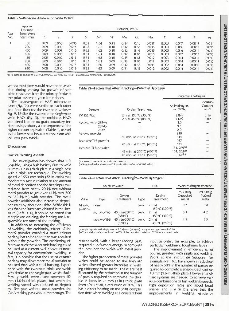
Table 22—Repl icate Analyses
Pass
No.
1
2
(a) All
Approx. Distance,
from Weld Start, mm.
30 200 400 650
30 200 400 650
samples contained 0.03'
c 0.09 0.09
0.09
0.09 0.08
0.08 0.08
0.08
_Cr. 0.02"
on W e l d W14<a>
S
0.010 0.010 0.009 0.010 0.010 0.010 0.010 0.010
,V, 0.01 %Sn,
P
0.016 0.015 0.015
0.015
0.015 0.015
0.015
0.016
Si
0.32 0.32 0.32 0.31 0.32 0.33 0.33 0.33
Mn
1.64 1.62 1.62 1.63 1.62 1.61 1.60 1.62
0.01%Co. <0.0003.„Ca <0.005%Pb,
Ni
0.11 0.10 0.10 0.10 0.10 0.09 0.09 0.09
<0.005%Zn
Element,
Mo
0.14 0.12 0.12 0.12 0.15 0.13 0.12 0.11
wt. %
Cu
0.18 0.18 0.18 0.18 0.18 0.18 0.18 0.18
Nb
0.017 0.015 0.015 0.015 0.012 0.012 0.011 0.012
Ti
0.003 0.003 0.003 0.003 0.003 0.003 0.002 0.002
Al
0.017 0.016 0.016 0.017 0.014 0.014 0.014 0.014
B
0.0015 0.0012 0.0011 0.0011 0.0014 0.0011 0.0010 0.0011
As
0.011 0.011 0.010 0.010 0.010 0.010 0.010 0.010
able during cooling for growth of side plate structures from the primary ferrite at the prior austenite grain boundaries.
The coarse-grained HAZ microstructures (Fig. 14) were similar to each other and finer than for the two-pass welds — Fig. 9. Unlike the two-pass or single-pass weld HAZs (Fig. 3), the multipass HAZs contained little or no grain boundary ferrite; this is probably a consequence of the higher carbon equivalent (Table 1), as well as the lower heat input in comparison with the two-pass welds.
Discussion
Practical Welding Aspects
The investigation has shown that it is possible, using a high basicity flux, to weld 30-mm (1.2-in.) thick plate in a single pass with a triple arc technique. The welding speed of 550 mm/min (22 in./min) was moderately fast in relation to the amount of metal deposited and the heat input was reduced from nearly 20 k)/mm without metal powder to just over 14 k j /mm (500 to 355 kj/in.) with powder. The metal powder additions also increased deposition rates by about one third. While this is less than the increases claimed in the literature (Refs. 1-6), it should be noted that in triple arc welding, the leading arc is responsible for most of the melting.
In addition to increasing the efficiency of welding, the cushioning effect of the metal powder enabled a much thinner backing bar to be used than was required without the powder. The cushioning effect was such that a ceramic backing could be used at a current well above its nominal capacity for conventional welding. In fact, it is possible that the use of ceramic backing may allow more metal powder to be used than with a steel backing. Experience with the two-pass triple arc welds was similar to the single-pass welds. Satisfactory welds were made between 40-mm (1.6-in.) thick plates, but when the welding speed was reduced to deposit the first pass without metal powder, the CMA tacking pass was burnt through. The
Table 23—Factors that Affect Cracking—Potential Hydrogen
Potential Hydrogen
Sample
OP122 Flux
Mn-Mo wire 2684A 2684B 2689
Mn-Mo powder
Lean Mo-Ti-B powder
Rich Mo-Ti-B powder
Drying Treatment
2 h at 150°C (300°F) 2 h at 450°C (840°F)
---
45 min. at 250°C (480°F)
45 min. at 250°C (480°F)
45 min. at 250°C (480°F) 45 min. at 300°C (570°F)
As Hydrogen, mL/100g
236(a)
112<a>
1.0 1.1 2.9 210 114 197 111
1 7 1 , 239<b>
104, 205<b>
- , 1 2 6 < b >
Moisture Content
wt-%
0.19 0.09
-— — ---— -— —
(a) Values converted from moisture contents. (b) Samples dried and analyzed 23 weeks after earlier (adjacent) values.
Table 24-
Wire
Mn-Mo (2684A)
—Factors that Affect Cracking*3
Metal Powder5
Type
none
rich Mo-Ti-B
rich Mo-Ti-B
Drying Treatment
—
45 min-250°C (480°F)
45 min-300°C (570°F)
—Weld
Type
basic
basic
basic
Hydrogen
Flux
Drying Treatment
2 h at 150°C (300°F)
2 ha t 150°C(300°F)
2 h at 450°C (750°F)
Weld hydrc
mL/100g Deposited
metal
9.7
5.3
4.3
)gen content
mL/100g flushed metal
5.4
4.2
3.5
(a) Weld deposits with single wire at 2.0 kl/mm (51 kj/in.) on a grooved speciemn (Ref. 20). (b) The metal powder constituted —40% of the deposited metal and 32 5% of the fused metal.
repeat weld, with a larger tacking pass, required ~ 2 2 % more energy to complete the joint than the welds with metal powder.
The higher proportion of metal powder which could be added to the twin arc welds allowed greater increases in welding efficiency to be made. These are best illustrated by the reduction in the number of passes required to complete the double V joints in 75-mm (3-in.) thick plate from 40 to ~ 2 8 , a reduction of 30%. This has a direct bearing on the joint completion time when welding at a constant heat
input in order, for example, to achieve particular weldment toughness levels.
The improvement in efficiency is, of course, greatest with single arc welding. Work at the Institut de Soudure, for example (Ref. 10), has shown a reduction of nearly 50% in the number of passes required to complete a single-sided joint on 40-mm (1.6-in.) thick plate. However, mul-tiarc systems are needed to achieve various combinations of fast welding speeds, high deposition rates and good bead shape, and it is in this area that the improvements in welding efficiency
WELDING RESEARCH SUPPLEMENT 1201-s

should be of considerable use. Although significant reductions in the
proportion of base plate diluted into the weld were obtained in the single-pass weld onto a ceramic backing and with a single arc (Ref. 10), little change in dilution was found in other welds. Although metal powders reduced penetration, their use appeared to increase the weld width, as can be seen in Figs. 1, 6 and 10.
The weld shapes obtained were generally better than from the comparison welds and no defects associated with the use of metal powder were found. However, when introducing metal powders, care must be taken to avoid incomplete root fusion, either by reducing backing
bar thicknesses in single sided welds or by suitably increasing the current of the leading arc. On the other hand, the change from a metal powder system will increase the risk of melt through.
No information regarding the suitability of different powder feeding arrangements could be obtained during the investigation, partly because the available metering device (which was used to prelay powder in the groove ahead of the leading arc) did not have the required capacity, so that the powder had to be prelaid, and partly because of difficulties experienced from magnetic fields when trying to feed metal powders via the welding wires instead of under the flux.
Cracking
During the project, only two minor instances of solidification cracking were encountered, both in welds without metal powder. Weld depth/width ratios were generally reduced by the use of metal powder and this should reduce the risk of solidification cracking. However, with mul-tiarc welding, the use of metal powder does not lead to any decrease in the dilution of base metal into the weld pool (except where ceramic, as opposed to steel, backings can be used). Metal powders by themselves cannot, therefore, be expected to reduce the risks of solidification cracking, as in the single-pass welds, un-
> ' • J' . ' ' ^
- > - - ' - " '- •' ' ' • - . „ ' ' ' •
' - " ' ' - . . ' t i *-' H * ', ' ' **"">' ? "L . r 1 ' '> "*'•- -V " *>> -(' * * * »- • ** ' ft ••
n . ••- . ij, •••-'-'• ••' -« * *" , * "*J-AS • -- . E
* ' • •: '* ' • V " . > " - - *
i , ; ! ; ; . •• * . ' . . . ' . / * • ' . ' ,
:A, -: ' '• v ''•''•
' . • - - • • • ' , . . ' • • , 5 - : ' : ••'•'• •-.
. s '• -5 • ..." -• : .
. ;-;p . •
, -. . • • • . i • • , V
' '- - '//.V, >& • . *.
-. . . -.
' . , . ' . - . - . - . - • • • . • • • -
• • • ' • • ; i ••< • •
. .•'< , .
~ -r^5"\\y'i - 5 ' , . ' " - . • '
5 -;-.
- 7 , '
. • r, -> * *
•- ' -.-'' ' W • . . . % ; ^ ' ,• '.
• • - . . " ' \ • V
* < " " " : ' ' • • .
* ' ' - • •' ^ '• ; "
*\- * / • v ' ' '-' * * • " ' . •
' : - ^ • ^
• ^ ' - " * ; * , ,
ly
5-£^';i ! ':. V^v'"''5
• 1 . ' • " . * - " -
- - , \ ' . *.-
) . 7'' o
~" iJ$ ••'-•
• >
;';'-^ ':*' I '0'V.;">-* -.' - v v
- '-\v
"-''-•*'.'-.'JJ< ^l- *-":>; • • . - . - . < • • • " . - . - ' . . »
,'• - • Jy.
«
i~ ' .' '• .* *- , ' r -
.*"\?".-'.- ,. V-' , *,,
' H V fc '
r • . • " . " - ^ f *
- —.
•^'vs.'..-v'.- . / fc.':"\ -,:
' -* -. \ s : ' • ' . - w-"7fc *•_•
v4 '^'i~P;K
) S x" " . -.''
'" ' \
'•• , %• • " * - . • < , > v '•-
c
• • • ' • • - . ; • . , • • • ; • - . • •
• * ; • ' - • - . / . > ' 5 - ; • ? •••• . •
. - * - • • - ' - •
i .
.»• h • K . -.
'.-. v
D
3Wi ' r-o :;-. _>.
: ' ." " ..y-:.y -,.• • . . • ....• fc . ' - v . . ' - *; ;
__i ! , . • '•
. • - .
%> .'>
•
**;•-, , v
• • _ - i . '
,^\
« . ' •* j
• • • i
- _ ^ 7 > _ y . -;
. ^ ^ ' ; : - . - ' • ' .
. •' r*° * v. •• " . • ' k . -
'
• . ' ' ->
' • M a fc *5 !
- •
Fig. 13 —Microstructures of as-deposited multipass weld metal. A — W16, S3 wire, 3 kj/mm, cap; B—W16 root; C— W19, S3 wire, 5.5 kj/mm, cap; D-W19, root; E- W18, S3 wire, Mn-Ni-Mo powder, cap; F- W18, root. (320X)
202-s I AUGUST 1991

Table 25—Incidence of Cracking
Weld No.
W10 W15 W8 W13 W 9 W14 W7 W12
Wire Type
0.5Mn/Mo-Cr-Ti-B 0.5Mn/Mo-Cr-Ti-B Mo-Ti-B Mo-Ti-B 1.5Mn 1.5Mn 1.5Mn-Mo 1.5Mn-Mo
(a) Base plate 0.38CE. (b) From Table 11.
Metal Powder
— -
lean Mo-Ti-B lean-Mo-Ti-B rich Mo-Ti-B rich Mo-Ti-B Mn-Mo Mn-Mo
Drying Temperature, CC (°F)
Flux B
150 (300) 400 (750) 150 (300) 450 (840) 150 (300) 450 (840) 150 (300) 450 (840)
Metal Powder
-—
250 (480) 300 (570) 250 (480) 300 (570) 250 (480) 300 (570)
Weld Second Pass
Compositional Parameters'3'
CE
0.37 0.35 0.39 0.39 0.40 0.40 0.43 0.41
Mean Second Pass Weld Hardness*'
HV5
216 202 226 223 240 223 235 208
Incidence of Cracking
severe none detected severe one detected severe one detected severe none detected
less positive steps are taken to use the powder to control the weld metal composition. In this context, it should be noted that, even in the two-pass and multipass welds, the use of metal powders did not lead to lower carbon contents, the relevance of this being that carbon is the major compositional factor in promoting cracking (Ref. 11).
Hydrogen cracking (mostly in the weld metal) was only encountered in the two-pass welds, although the preheat and interpass temperature levels used for the multipass welds were admittedly conservative for the composition of steel actually used, although not necessarily for the weld metal. Because there is not yet a standardized method for the determination of weld hydrogen contents in multiarc welds, it is difficult to estimate the critical levels for cracking in the metal powder welds. The tests at the Institut de Soudure (Ref. 15) showed that the use of a metal powder of very high potential hydrogen levels led to only a small increase in the weld hydrogen content of a single arc weld when using a flux (OP121TT) capable of giving very low hydrogen levels. With the two-pass flux giving a higher hydrogen content of almost 10 mL/100 g of deposited metal (Table 24), the metal powder addition actually led to a fall in weld hydrogen content in a single arc deposit in the weld hydrogen determinations. The use of multiarc welding with metal powder will reduce the influence of the powder on weld hydrogen content, so that it is likely that the critical hydrogen level for cracking with the present two-pass welds without preheating is close to that obtainable with the two-pass flux dried at 400°C (750°F), a value probably ~ 5 mL/100 g deposited metal, i.e., ~3.6 mL/100 g fused metal. This value is much lower than led to cracking at weld metal carbon equivalent levels up to 0.43 in the results on 25-mm plate analyzed by Fletcher and Nicholls (Ref. 16), and it must be concluded that the increase in weld bead size and the increase in thickness from 25 to 40 mm have had a major effect
Table 26—Summary of Multipass Welding Parameters'3'
Weld No.
Powder type Total current, A Welding speed, mm/min (in./min) Arc energy, k)/mm (kj/in.) Total no. of passes
W16
1650 1225 (48)
3.0-3.1 (76-79) 40
W17
1.5Mn 1650 1225 (48)
3.0-3.1 (76-79) 27
W 1 8
Mn-Ni-Mo 1650 1225 (48)
3.0-3.1 (76-79)
29
W 1 9
1650 675 (27)
5.4-5.6 (137-142)
25
(a) First side, 50 deg V, 50 mm |2 in.) deep, 8 mm (0.31 in.) root face; second side 30 mm (1.2 in.) max. width tapered to 5 mm (0.2 in.) root radius; tandem arc, DCEP (vertical), AC 20 deg 1.5%Mn wire, feed rate —17 kg/h (37 Ib/h), powder feed rate (12 kg/h (26 Ib/h). Preheat 150°C (300°F) max. interpass 200°C (400°F), basic flux dried 350°C (660°F). powder dried 250°C (480°F).
on increasing the risk of weld metal hydrogen cracking. These results are consistent with Vilpas, et al, observations (Ref. 9) that drying of metal powder was not necessary to avoid hydrogen cracking (presumably they used atomized powders).
One possible influence of metal powder additions on weld metal hydrogen cracking that has not been explored is weld bead size. It is likely that if the beads of similar composition, hardness and hydrogen level are deposited using similar welding parameters, the metal powder weld bead will be more likely to suffer hydrogen cracking since it will be larger, and the hydrogen it contains will, thus, diffuse out more slowly. This effect of increasing bead size (without metal powder) has been observed by Pargeter (Ref. 17).
Weld Metal Toughness
The poor toughness of the single-pass welds deposited without metal powder was not just a result of the high heat input, but was largely due to their low oxygen contents in relation to the aluminum picked up by dilution, mainly from the base plate. The harmful effects of excessive aluminum contents on weld metal toughness are well documented (Refs. 18-22), although weld metal aluminum contents associated with Charpy transition temperatures above ambient have usually been ~0.03%AI and above (Refs.
21, 22). However, the present welds made without metal powder had unusually low oxygen contents of 0.012 and 0.016%, partly no doubt because of the slow solidification time and the low plate and wire oxygen contents, so that less aluminum (~0.020%) was sufficient to seriously impair both microstructure and toughness.
The metal powder addition helped to restore the microstructure and properties in three ways, namely by increasing the weld oxygen content, by adding metal powder, which itself was free from aluminum, to the weld and by adding titanium, which may have been useful in promoting the formation of acicular ferrite (Ref. 23), particularly as welds W1 and W3 without metal powder did not contain detectable amounts (<0.002%) of this element.
With the amount of powder used, although the intended level of 0.2% Mo was observed in weld W4, boron was not detected, although it had been hoped to alloy ~0.002%. This boron addition should have had the effect of further reducing the proportion of grain boundary ferrite in the weld metal and thus increase the proportion of acicular ferrite and improve toughness. This lack of boron may explain why the weld metal toughness values were lower than had been achieved by Baach (Ref. 4). He used iron powder with Mo-Ti-B alloyed flux cored wires to weld 28-mm (1.1-in.) plate with tandem arcs at an arc energy of 12.8 k)/mm (325 kj/in.)
WELDING RESEARCH SUPPLEMENT 1203-s

Fig. 14 — Coarse-grained nonreheated multipass weld HAZ microstructures.
A — W16, no metal powder, 3 kj/mm; B—W19, no metal powder, 5.5 kj/mm;
C— W17, S3 wire and powder, 3 kj/mm. (320X)
* J
"*S
'Bt^V
" • . A : ' i - ' - • " • ' : '(• , • ; '•
, m •
• • ' ^ • • • - ^ _ _
•'•-*'•/"•'; y&try-V; -_-<-. - - • £ . , , - ' . i '»
| |
• ' ' - • • - * ' ' ' ' •
7 ''•-' M - • . ' / • - * .
. V - •• - "
*^iij *£#* • f
r * , • * • ; « - . . ' . - -
c/-5. ^
r i y . . - " / • } : - .
• » '*' *' \ \ •
±~* $->\-• -W v-j i -! .>.- . . - . , • -
\ . . - • :
,':vi I i
"¥£ •
. . . ,V .- v • ; '
' . > •
v X
• >'<5
v . . i _
, '-.
- . • • •
.. /
• 5 - : . ,
__. .
!.'-'
^ ;
, , " ]
- •' £ y
. *" ___;_, ,
' -,.•"* ¥•
->' s 3 ' * " -
••
; . ' • '
. '.*. "."* '
-J , _ *
• ' - • •
. - - ^ 3 S W j
. '
•7? , ,
<:&»
• J .
^
-v v
v>n rC
•' "£' ' " ' • " "'.''•. ' ' ' •' •
j . ^ - ' y - r .,i . . . .,;• >
. -
_-"v"" j >, . V ' 5 V 7 ' . i ' • , -
' - " - 5't • -
. -f ..
• : • ' . - 5 . , • • , . ' .
* '.
•5 '.
-'. . t
and obtained Charpy values of 59 ) at - 4 0 ° C (43 f t / lb at -40°F), more than was obtained in the present work.
Despite the use of a low-carbon plate, the toughness of all the two-pass weld metals, expressed in terms of Charpy transition temperature, was better than that of the coarse grained HAZ regions, and in the best case (Weld W13, Table 14) was not very different from the base plate. It is considered that the toughness of Weld W15 without metal powder fell below that of W13 for two reasons, firstly the higher arc energy used, and secondly the lower Mo and Mn contents (Table 11), which led to a microstructure containing more grain boundary ferrite (cf Fig. 9A and B). Although the Mn-Mo wire and powder weld W12 had similar contents of these elements to W13, the absence of boron led to a higher proportion of grain boundary ferrite, while the acicular ferrite in the intragranular microstructure was of high aspect ratio, possibly because of the very low titanium content (<0.002%). These microstructural features led to the Mn-Mo weld W12 being less tough than W13 or W14, which contained both titanium and boron.
The excellent toughness of the two-pass metal powder weld W13 can be appreciated in comparison with the multipass results as-welded (Table 15) for, despite the faster cooling rate and the presence of reheated, refined weld metal
in the multipass welds, the 1.5% Mn multipass weld metals were no tougher than W13 and the alloyed Mn-Mo weld was only tougher by some 10° to 15°C(18° to 27°F transition temperature. The relatively poor performance of the 1.5% Mn multipass welds is a result of the high proportion of grain boundary ferrite in the as-deposited microstructures, due to a low level of alloying, and to the absence of detectable amounts of titanium, which can help to nucleate acicular ferrite (Ref. 23) and thus reduce the proportion of ferrite with aligned second phase.
The 1.5% Mn welds showed variable behavior on PWHT, the only weld to show a significant improvement was W17, and then only in the cap regions, which had the lowest carbon content and carbon equivalent of 0.08% and 0.35, respectively. The reduction in toughness of the Mn-Ni-Mo weld, W18, on PWHT is not unexpected, due to its molybdenum content, although the change in hardness on PWHT differed little from that of the C-Mn weld metals. This consumable type is, however, intended to provide good retention of strength and toughness in welds of higher arc energy than were tested in the present work. Certainly this weld metal was harder after PWHT than the 1.5% Mn welds, and the toughness after PWHT (35 J at - 5 0 ° to - 5 5 ° C or 26 f t / lb at —58° to —67°F) was as good as all except one of the 1.5% Mn welds.
The welds, both two-pass and multipass, to which titanium had not been deliberately added, all contained <0.002%Ti, due to the absence of significant amounts of titanium in the base plate, welding wire and flux. As this element is known to play a significant role in the nucleation of acicular ferrite (Refs. 23-26), albeit in small quantities, it would be worthwhile adding a small quantity to alloyed metal powders, particularly those intended to give tough weld metals at fairly high arc energies.
HAZ Toughness
In no case was the reduction in arc energy brought about by the use of metal powder additions with multiarc welding sufficient to improve HAZ toughness by a significant amount. This observation is supported by the results of tests at the Institut de Soudure (Ref. 10) on simulated HAZs having cooling times appropriate to welds with and without metal powder. In the case of the one- and two-pass welds (Tables 13, 14), the transition temperatures were not low enough to match those of the weld metal, despite the use of a steel of relatively low carbon content (0.10%) for the two-pass welds. To make full use of the good toughness levels that can be achieved in such high heat input weld metals, it may be necessary to use them with steels resistant to grain coarsening in the HAZ. Although such steels
204-s | AUGUST 1991

Table 27
Weld No.
W16
W19
W17
W18
—Composition of Multipass Welds
Powder Type
none
none
Mn
Mn-Ni-Mo
Region
root cap root cap root cap root cap
C
0.11 0.09 0.09 0.08 0.09 0.08 0.10 0.08
S
0.007 0.008 0.005 0.005 0.006 0.007 0.005 0.005
P
0.012 0.015 0.015 0.016 0.010 0.011 0.011 0.012
Si
0.26 0.25 0.33 0.32 0.27 0.25 0.35 0.39
Mn
1.49 1.51 1.51 1.56 1.48 1.49 1.54 1.65
Ni
0.05 0.05 0.05 0.05 0.04 0.04 0.34 0.44
Element,
Mo
0.02 0.02 0.01 0.01 0.01 0.01 0.17 0.23
wt-%
Cu
0.23 0.26 0.19 0.19 0.14 0.13 0.14 0.13
Nb
0.009 <0.002
0.012 0.003 0.008
<0.002 0.009
<0.002
Al
0.016 0.012 0.016 0.014 0.013 0.010 0.016 0.013
o 0.032 0.024 0.024 0.026 0.035 0.031 0.027 0.029
N
0.009 0.008 0.009 0.009 0.008 0.007 0.008 0.007
CE
0.39 0.38 0.37 0.37 0.36 0.35 0.43 0.45
Note, all samples contained 0.03-0.07Cr, «_0.005V, <0.002Ti. <0.0003B, Ca, «0 .014As, <S0.02Sn, 0.01Co. <0.005Pb. Zr.
have given good toughness in the HAZ of high heat input welds (Ref. 4), there may still be problems in achieving adequate toughness as the weld fusion line.
The Charpy transition temperatures for the as-welded multipass HAZs appeared to be as good as for the weld metals and base plate, but the metal powder weld HAZ was apparently less tough than the HAZ of the welds without metal powder, although the position was reversed on PWHT. Although some of the HAZ toughness effects may have been masked because the sampled regions of different HAZs probably contained different proportions of coarse and fine microstructure, it is likely that relatively high niobium content of 0.041% in the steel gave a HAZ that exhibited little or no softening on PWHT (Table 12) so that the toughness was impaired. Nevertheless, it is likely that PWHT can give useful tempering of a small hard HAZ region which, although too small to affect toughness levels as assessed by Charpy testing, can give rise to very low CTOD results.
Conclusions
An investigation into the use of metal powders during submerged arc welding of tough structural C-Mn-Nb steels has been carried out using twin and triple arc systems. Single, two, and multipass welds were examined in plate thicknesses from 30 to 75 mm (1.2 to 3 in.). The results of the program are as follows:
1) Metal powders allow a considerable improvement in the efficiency of submerged arc welding. The increase in metal deposited with a fixed heat input is approximately 30% with twin arcs and 20% with triple arcs, compared with nearly 50% with a single arc.
2) The improved efficiency results in improved joint completion rates when multipass welding at a fixed heat input. The number of passes required is reduced by approximately 30%, with twin arcs compared with nearly 50% for a single arc.
3) Metal powders lead to reduced penetration into the base metal or backing bar. Although this can lead to incomplete fusion defects if a direct substitution is
made, metal powders can be used with thinner backing bars and also with ceramic backings at much higher currents than if metal powders are not used.
4) The reduction in penetration when using metal powders reduced the depth/ width ratio of the welds and, hence, the risk of solidification cracking.
5) Agglomerated alloyed metal powders exhibited high potential hydrogen levels, which increased during storage after opening their packets. This potential hydrogen had little effect on weld hydrogen contents, as determined by a modification of the IIW test, or on the risk of cracking when welding with a constant weld bead size.
6) Hydrogen cracking was not encountered in single-pass unpreheated welds in 30-mm (1.2-in.) thick plate, nor in multipass welds in 75-mm (3-in.) thick plate, which were preheated to 150°C (300°F). Transverse weld metal cracks at 45 deg to the plate surface were encountered in two-pass, unpreheated welds in 40-mm (1.6-in.) thick plate, regardless of the use of agglomerated metal powders, except when the flux had been dried to give less than approximately 3.6 mL/100 g fused metal (5 mL/100 g deposited metal) using weld metals of the Mo-Ti-B and Mn-Mo types.
7) Metal powders did not significantly reduce the proportion of base plate diluted into the weld, except when a ceramic backing was used.
8) With a constant arc energy, the use of metal powder did not affect the weld cooling in terms of the 800° to 500°C cooling time. At constant bead size, no improvement in HAZ toughness could be detected with the Charpy test, although a substantial increase in the cooling rate was obtained.
9) In no instance did the use of metal powders impair weld metal toughness. Indeed agglomerated metal powders could be used to optimize weld metal toughness without the use of possibly expensive alloyed solid wires. This was most effectively demonstrated in a single pass weld, where the harmful effects of aluminum diluted from the base plate were overcome and the weld metal Charpy
transition temperature reduced by over 100°C (180°F).
10) With metal powders, the following 28 J (20 ft/lb) transition temperatures were achieved in the weld metal at the thicknesses given: single-pass welds with Mn-Ti-B-Mo metal powders, - 4 0 ° C (—40°F); two-pass welds with Mn-Ti-B-Mo metal powders, - 7 5 ° C (-135°F); multipass welds with Mn metal powders, - 7 5 ° C (-135°F); multipass welds with Mn-Ni-Mo metal powders, —90°C (-160°F).
Acknowledgments
The author would like to thank the Research Members of The Welding Institute and the Commission of European Communities for the provision of funds. Thanks are due to K. W. Middleton and other colleagues for their help with the experimental work and advice and to the Institut de Soudure personnel who carried out the weld hydrogen determinations as well as cooperated in the larger project. Messrs. Oerlikon are thanked for the supply of metal powders, and it should be emphasized that the commercial consumables used were obtained several years ago. It is understood that the two-pass flux is now produced to give lower weld hydrogen levels and also problems due to very low weld Ti contents are no longer likely with these consumables.
References
1. Ivochkin, 1.1., etal. 1969. Prospect for the use of powdered filler metal in fusion welding. Weld Prod No 6, pp. 61-65.
2. Troyer, W., and Mikurak, J. 1974. High deposition submerged arc welding with iron powder joint fill. Welding lournal 53 (8):494-504.
3. Raty, P. T. 1974. Unionfill is the latest development in submerged arc welding process. Canadian Welder and Fabricator, pp. 22-25.
4. Baach, H. 1980. Gutesteigerung beim UP-Schweissen trotz Leistungssteigerung. Oerlikon Schweissmitteilungen 38(91): 13-23.
5. Kohno, A., and Barlow, |. A. 1982. Improved submerged arc productivity with metal powder additions. Welding Institute Research Bulletin, pp. 377-385.
6. Fraser, R., etal. 1982. High deposition rate submerged arc welding for critical applications. Proceedings of 2nd Int. Conf. on Offshore
WELDING RESEARCH SUPPLEMENT 1205-s

Welded Structures, The Welding Institute, London, England. Paper 12.
7. Eichhorn, F., and Kerkmann, M. 1983. Submerged arc welding with metal powder additions. IIW Doc XII-804/83.
8. Rodgers, K. ]., and Lochhead, ). C. Submerged arc welding with metal powder additions, productivity and properties. Welding Journal 66 (2):21-27.
9. Vilpas, M., etal. Mechanical properties of submerged arc welds with metal powder addition, IIW Docs XII-1151-89 and IX-1608-90.
10. Casse, A.,andGaillard, R. 1986. Amelora-tion de la productivite par addition de poudre metallique lors de I'execution de soudres par le precede de soudage a Tare sous flux en poudre. IS Final Report on Project 7210/KA311 to CEC.
11. Bailey, IM., and lones, S. B. 1977. Solidification cracking of ferritic steels during submerged arc welding. The Welding Institute.
12. Pargeter, R. ). 1978. Yield strength from hardness —a reappraisal. TWI Res. Bull., 19 (11):325-326.
13. Bailey, N. 1985. Improved productivity through metal powder additions to submerged arc welds. TWI reports 3777/3/83 and 3777/ 4/85 on project 7210/KA-808 to CEC, March
and September. 14. Coe, F. R. 1973. Welding steels without
hydrogen cracking. The Welding Institute. 15. Casse, A., and Gaillard, R. 1984. Amelora-
tion de la productivite par addition de poudre metallique lors de I'execution de soudres par le procede de soudage a Tare sous flux en poudre. IS Progress Report No. 2 on project 7210/ KA311 to CEC, Nov.
16. Fletcher, L, and Nicholls, D. 1981. Hydrogen assisted cracking in submerged arc welding. AWl and NZIW joint conf. Integrity of Welding, Christchurch, N. Zealand.
17. Hart, P. H. M. 1989. Trends in welding materials for offshore structures. Int. Conf. EVALMAT, Kobe.
18. Tenkula, )., and Heikkinen. V. K. 1978. The effect of parent plate aluminum on the properties of two wire submerged-arc weld metal in Nb microalloyed steel. Weld Res. Int. 8(5):369-376.
19. Yoshino, Y., and Stout, R. D. 1979. Effect of microalloys on the notch toughness of line pipe seam welds. Welding journal 58(5):59-s to 68-s.
20. Devillers, L, and Riboud, P. V. 1980. Metallurgie et proprietes mecaniques du metal
fondu en soudage sous flux. IS final report to CEC No. 9210 KA/304 (81-40-77), Oct.
21. Terashima, H., and Hart, P. H. M. 1984. Effect of Al in C-Mn steel on microstructure and toughness of submerged arc weld metal. Welding lournal 63(6):173-s to 183-s.
22. Ibid. 1983. Effect of flux T i 0 2 and wire Ti content on tolerance to high Al content of submerged arc welds made with basic fluxes. Paper 27, Welding Inst. Conf. The Effects of Residual, Impurity and Micro-Alloying Elements on Weldability and Weld Properties.
23. Es-Souni, M., Beaven, P. A., and Evans, G. M. 1989. Micro analysis of inclusion/matrix interfaces in weld metals. GKSS report 89/E/58.
24. Evans, G. M. The effect of titanium on the microstructure and properties of C-Mn all-weld deposits, Welding lournal, to be published.
25. Bailey, N. 1984. Ferritic steel weld metal microstructures and toughness. Proc. Centenary Conf., Univ. of Sheffield, Dept. of Metallurgy, The Metals Soc.
26. Devillers, L. 1984. Etude metallurgique du metal fondu en soudage automatique sous flux solide. Final report to CEC, project No. 7210.KI/309, Dec.
WRC Bulletin 346 August 1989
WFI/PVRC Moment Fatigue Tests on 4 x 3 ANSI B16.9 Tees
By G. E. Woods and E. C. Rodabaugh
The Markl-type fatigue test data presented in this report have been needed for a number of years to establish i-factors (SIFs) for forged tees with d / D ratios between 0.5 and 1.0 that conform to the ANSI B16.9 standard. These new data will provide improved design rules for both nuclear and industrial piping systems.
Publication of this report was sponsored by the Subcommit tee on Piping Pumps and Valves of the Pressure Vessel Research Commit tee of the Welding Research Council. The price of WRC Bulletin 346 is $25.00 per copy, plus $5.00 for U.S. and $10.00 for overseas postage and handling. Orders should be sent with payment to the Welding Research Council, Room 1301, 345 E. 47th St., New York, NY 10017.
WRC Bulletin 356 August 1990
This Bulletin contains three reports involving welding research. The tit les describe the contents of the reports.
(1 ) Finite Element Modeling of a Single-Pass Weld By C. K. Leung, R. J. Pick and D. H. B. Mok
( 2 ) Finite Element Analysis of Multipass Welds By C. K. Leung and R. J. Pick
(3 ) Thermal and Mechanical Simulations of Resistance Spot Welding By S. D. Sheppard
Publication of the papers in this Bulletin was sponsored by the Welding Research Council. The price of WRC Bulletin 356 is $35.00 per copy, plus $5.00 for U.S. and $10.00 for overseas postage and handling. Orders should be sent with payment to the Welding Research Council, 345 E. 47 th St., Room 1301, New York, NY 10017.
206-s | AUGUST 1991