subject: pulleys shaft replacement on gts diesel … · di seguito riportiamola procedura per la...
TRANSCRIPT

Bollettino Tecnico — Technical Bulletin GTS
Code 00555600123 1 / 14
Ref. GS_16
Oggetto: SOSTITUZIONE ALBERO PULEGGE DI RINVIO SU UNITÀ GTS DIESEL Di seguito riportiamo la procedura per la sostituzione dell’albero pulegge del tendicinghia per le unità GTS Diesel e il procedimento per il corretto tensionamento delle cinghie. Subject: PULLEYS SHAFT REPLACEMENT ON GTS DIESEL UNITS Hereunder we describe the procedure about the replacement of the belt-tightener pulleys shaft for GTS Diesel units and regarding the correct belts tightening process.
01 Rimuovere il sedile e il cofano motore. Remove the seat and the engine hood.
02 Accedere al lato sinistro del vano motore, dove sono presenti il radiatore e le cinghie. Approach to the left hand side of the engine room, where there are the radiator and the belts.

Bollettino Tecnico — Technical Bulletin GTS
Code 00555600123 2 / 14
03 Rimuovere le due consolle laterali e il coperchio del vano pompa. Remove the two side consoles and the cover of pump space.
04 Togliere le piastre supporto console su entrambi i lati. Remove the console support plates on both sides.
05 Togliere la traversa. Remove the crossbar.
Bollettino Tecnico — Technical Bulletin GTS
Code 00555600123 3 / 14
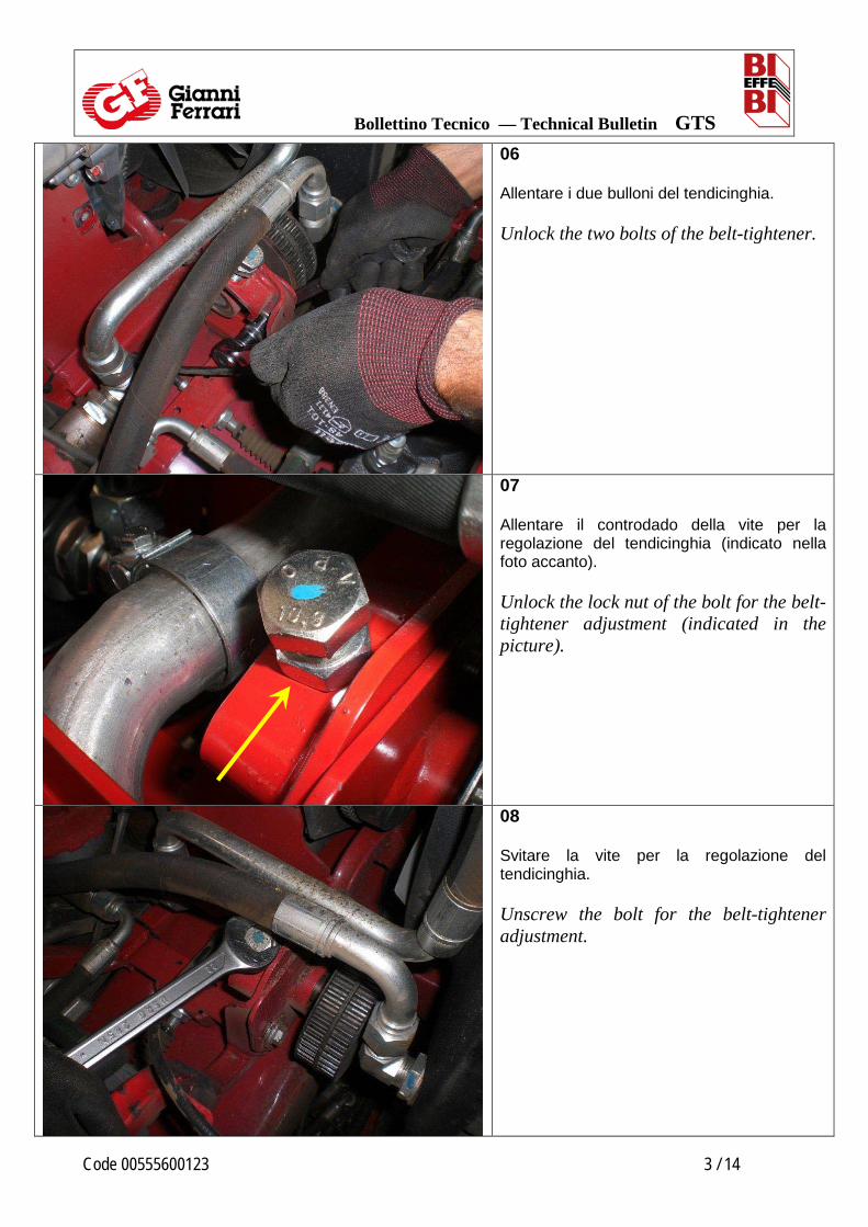
06 Allentare i due bulloni del tendicinghia. Unlock the two bolts of the belt-tightener.
07 Allentare il controdado della vite per la regolazione del tendicinghia (indicato nella foto accanto). Unlock the lock nut of the bolt for the belt-tightener adjustment (indicated in the picture).
08 Svitare la vite per la regolazione del tendicinghia. Unscrew the bolt for the belt-tightener adjustment.

Bollettino Tecnico — Technical Bulletin GTS
Code 00555600123 4 / 14
09 Rimuovere le cinghie dalle pulegge. Remove the belts from the pulleys.
10 Togliere i due bulloni di fissaggio del tendicinghia e rimuovere il supporto. Remove the two fixing bolts of the belt-tightener and remove the support.
11 Rimuovere il seeger dall’albero pulegge. Remove the circlip from the pulleys shaft.

Bollettino Tecnico — Technical Bulletin GTS
Code 00555600123 5 / 14
12 Svitare il dado autobloccante che fissa le pulegge all’albero. Unscrew the self locking nut that fixes the pulleys to the shaft.
13 Rimuovere le pulegge e le loro chiavette dall’albero rinvio. Remove the pulleys and the their keys from the transmission shaft.
14 Estrarre l’albero dal supporto tendicinghia e prendere il nuovo albero rinvio pulegge (p/n 92006000009) assieme ai due distanziali. Extract the shaft from the belt-tightener support and take the new pulley transmission shaft (p/n 92006000009) together the 2 spacers.

Bollettino Tecnico — Technical Bulletin GTS
Code 00555600123 6 / 14
15 Estrarre un cuscinetto dal supporto tendicinghia. Extract one bearing from the belt-tightener support.
16 Prendere il distanziale più grande (p/n 92006000033) e metterlo all’interno del supporto tendicinghia. Take the bigger spacer (p/n 92006000033) and put it inside the belt-tightener support.

Bollettino Tecnico — Technical Bulletin GTS
Code 00555600123 7 / 14
17 Riposizionare nel supporto tendicinghia il cuscinetto estratto precedentemente. Reposition into the belt-tightener support the bearing extracted before.
18 Inserire l’albero nel supporto tenditore. Insert the shaft into the support.
L’albero pulegge deve essere inserito dalla parte in cui il supporto cuscinetti è più lungo (come si vede nella foto accanto). The pulleys shaft must be inserted into the side which the bearings sleeve is longer (as shown in the picture).
Bollettino Tecnico — Technical Bulletin GTS
Code 00555600123 8 / 14
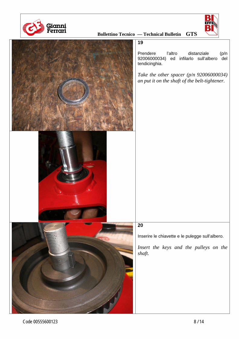
19 Prendere l’altro distanziale (p/n 92006000034) ed infilarlo sull’albero del tendicinghia. Take the other spacer (p/n 92006000034) an put it on the shaft of the belt-tightener.
20 Inserire le chiavette e le pulegge sull’albero. Insert the keys and the pulleys on the shaft.

Bollettino Tecnico — Technical Bulletin GTS
Code 00555600123 9 / 14
21 Avvitare il dado autobloccante sull’albero pulegge. Screw the self locking nut on the pulleys shaft.
22 Serrare il dado autobloccante dell’albero pulegge con la corretta coppia.
Tight the self locking nut of the pulleys shaft with the correct torque.
COPPIA DI SERRAGGIO
: 200 ± 5 Nm
TIGHTENING TORQUE
: 200 ± 5 Nm

Bollettino Tecnico — Technical Bulletin GTS
Code 00555600123 10 / 14
23 Prendere il tendicinghia, appoggiarlo al telaio della macchina e infilare le due cinghie sulle pulegge. Fissare il tendicinghia al telaio della macchina con i due bulloni, senza serrarli. Take the belt-tightener, lean it to the machine frame and insert the two belts over the pulleys. Fit the belt-tightener to the machine frame with the two bolts, without locking them.
24 Avvitare la vite per la regolazione della tensione delle cinghie e stringere il controdado della vite. Screw the belts adjustment screw and lock the nut for the screw
25 Avvitare i bulloni del tendicinghia.
Lock the two bolts of the belt-tightener.
Bollettino Tecnico — Technical Bulletin GTS
Code 00555600123 11 / 14
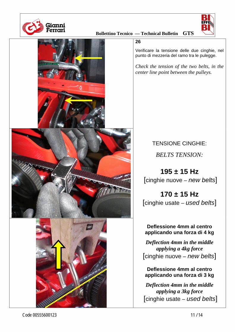
26 Verificare la tensione delle due cinghie, nel punto di mezzeria del ramo tra le pulegge. Check the tension of the two belts, in the center line point between the pulleys.
TENSIONE CINGHIE:
BELTS TENSION:
195 ± 15 Hz [cinghie nuove – new belts]
170 ± 15 Hz
[cinghie usate – used belts]
Deflessione 4mm al centro applicando una forza di 4 kg
Deflection 4mm in the middle applying a 4kg force
[cinghie nuove – new belts]
Deflessione 4mm al centro applicando una forza di 3 kg
Deflection 4mm in the middle applying a 3kg force
[cinghie usate – used belts]

Bollettino Tecnico — Technical Bulletin GTS
Code 00555600123 12 / 14
27 Regolare la tensione delle cinghie avvitando o svitando la vite. Adjust the belt tension by screw or unscrew the bolt.
28 Avvitare e stringere il controdado della vite per la regolazione. Screw and lock the nut for the adjustment.

Bollettino Tecnico — Technical Bulletin GTS
Code 00555600123 13 / 14
29 Avvitare i bulloni del tendicinghia, serrandoli con la corretta coppia.
Lock the two bolts of the belt-tightener, tightening with the correct torque.
COPPIA DI SERRAGGIO
: 55 Nm
TIGHTENING TORQUE
: 55 Nm
30 Verificare la tensione delle due cinghie. Check the tension of the two belts.
31 Se la tensione delle cinghie non è corretta, ripetere la procedura per il tensionamento. Se è corretta, rimontare la traversa. If the belts tension is not correct, repeat the procedure for the tensioning. If it is correct, reassemble the crossbar.

Bollettino Tecnico — Technical Bulletin GTS
Code 00555600123 14 / 14
32 Rimontare le piastre supporto consolle. Reassemble the console support plates.
33 Rimontare il coperchio di plastica Reassemble the plastic cover.
34 Rimontare le consolle laterali, il cofano motore e il sedile. Reassemble the side consoles, the engine hood and the seat.