subject 444 - industries | ul · subject 444 july 20, 2016 to: ... cable categories 5e, 6, 6a, 7...
TRANSCRIPT

Subject 444 July 20, 2016 TO: Subscribers to UL’s Performance Verification Services for Local Area Network (LAN) Cable
Verified in Accordance With National or International Specifications (DVBI) SUBJECT: Revised Testing and Follow-Up Service Requirements for UL’s LAN Performance Verification
Programs This bulletin will serve as the testing and Follow-Up Service reference document for all of UL’s LAN Performance Verification Programs and replaces UL’s March 14, 2013 Bulletin on the same subject. This bulletin will be updated as needed, when new or revised requirements are introduced into UL’s LAN Performance Verification Programs. This bulletin can be accessed at: http://industries.ul.com/news/bulletin-revised-testing-and-follow-up-service-requirements-for-uls-lan-performance-verification A. PERFORMANCE PROGRAMS UL presently offers LAN Performance Verification Programs to the Performance Standards described below: 1. ANSI/TIA-568C.2, “Balanced Twisted-Pair Telecommunications Cabling and Components Standards”
(otherwise known as the “UL Performance Category Program”); For Category 3, 5, 5E, 6, 6A. In addition, Category 8 cables are tested in accordance with TIA-568-C.2-1 Addendum 1. Any reference to ANSI/TIA 568C.2 for Category 8 cables shall also include the Addendum.
2. a) ISO/IEC 11801, "Information Technology - Generic Cabling for Customer Premises", Cable categories 5e, 6, 6A, 7 and 7A, For solid conductor cables that bear the surface mark for this standard, have had the cable performance evaluated to requirements as stated in IEC 61156-5, “Multi-Core and Symmetrical Pair/Quad Cables for Digital Communications - Part 5: Symmetrical Pair/Quad Cables with Transmission Characteristics up to 1,000 MHz-Horizontal Floor Wiring - Sectional Specification”. For stranded conductor cables that bear the surface mark for this standard, have had the cable performance evaluated to requirements as stated in IEC 61156-6, “Multi-Core and Symmetrical Pair/Quad Cables for Digital Communications - Part 6: Symmetrical Pair/Quad Cables with Transmission Characteristics up to 1,000 MHz- Work Area Wiring - Sectional Specification”.
b) ISO/IEC 11801, "Information Technology - Generic Cabling for Customer Premises", Cable categories 8.1 and 8.2. For solid conductor cables that bear the surface mark for this standard, have had the cable performance evaluated to requirements as stated in IEC 61156-9, “Multi-Core and Symmetrical Pair/Quad Cables for Digital Communications – Part 9: Cables for Channels with Transmission Characteristics up to 2 GHz – Sectional Specification”.
c) ISO/IEC 11801, "Information Technology - Generic Cabling for Customer Premises", Cable categories 8.1 and 8.2. For stranded conductor cables that bear the surface mark for this standard, have had the cable performance evaluated to requirements as stated in IEC 61156-10, “Multicore and symmetrical pair/quad cables for digital communications – Part 10: Cables for cords with transmission characteristics up to 2 GHz –Sectional specification”
3. NEMA WC 66, "Performance Standard for Category 6 and 7 100 Ohm Shielded and Unshielded Twisted Pair Cables”.
4. NEMA WC63.1, "Performance Standard for Twisted Pair Premise Voice and Data Communications Cables". (For Category 3, 5 and 5E Cables)
5. BS EN 50173-1, "Information Technology – Generic Cabling Systems – Part 1: General Requirements”. Cables that bear this surface mark for this standard, have had the cable performance evaluated to requirements

- 2 -
as stated in EN 50288-1, “Multi-Element Metallic Cables Used in Analogue and Digital Communication and Control - Part 1: Generic Specification”.
6. Any other Industry or Proprietary (client specification) Performance Standard requested by Subscribers and within the testing capabilities of UL’s Performance Verification Laboratory.
7. Other additional testing can be considered upon request.
The testing and Follow-Up Service requirements for each of the above Programs are defined in Item B of this bulletin. It is the responsibility of the Subscriber to purchase and maintain subscription services for the applicable Performance Standard(s) that their product was evaluated. The following will summarize the Testing and Follow-Up Service changes being introduced into UL’s LAN Performance Verification Programs:
The addition of Category 8 ANSI/TIA-568C.2-1 &Category 8.1 and 8.2 ISO/IEC 11801 test requirements.
B. NEW WORK TESTING AND FOLLOW-UP SERVICE REQUIREMENTS 1. Purpose and Scope The purpose of UL’s LAN Verification Program is to provide a third-party evaluation of data cables to categories of performance that are useful to system-design consultants, cable distributors, system users, cable manufacturers, and equipment manufacturers. The program covers determination of the performance category of cables as single components of data-transmission systems. The final acceptability of a particular cable for a specific data system needs to be determined by the system designer taking into account variables such as installation practices, cable length, connected equipment, and the operating environment. The applicable “performance category” is marked on the cable. The number of categories and the criteria for each category are based on established and developing industry Performance Standards and are subject to revision as requirements change.
UL Listed Cables Also Verified for Performance Listed cables, which have been investigated for use in accordance with ANSI/NFPA 70, "National Electrical Code”, can also be evaluated for transmission performance to the applicable LAN Performance Verification Programs described in Items A1 – A5 above. These Listed cables are covered under the Communications Cable (DUZX) category. UL Listed cables that have also been Verified for LAN Performance will be covered under the Data Transmission Cable Verified in Accordance With National or International Specifications (DVBI) category. A UL Listing for the cable is mandatory for participating in the “UL Performance Category Program” (Item A1 above).
Non-Listed Cables Verified for Performance
Non-Listed cables are for use where ANSI/NFPA 70, "National Electrical Code” code does not apply. They are intended for installation / use in countries other than the United States where the National Electric Code (NEC) is not applicable. These cables can be evaluated for transmission performance. These products will also be covered under the Data Transmission Cable Verified in Accordance With National or International Specifications (DVBI) category.

- 3 - 2. Cable Construction UL’s LAN Performance Verification Programs apply to 100-ohm twisted pairs that are cabled and then jacketed as data cables. UL Listed Communications Cables and non-Listed Data Transmission Cables are eligible if they consist of one of the following:
a. A jacketed unshielded and shielded (ScTP/FTP/STP) cable assembly of one (1) or more 100-ohm twisted pairs of 24 through 22 AWG solid copper metal coated or are not metal coated.
b. A jacketed unshielded and shielded (ScTP/FTP/STP) cable patch cable containing 24 through 26 AWG
solid or stranded copper conductors that are metal coated or are not metal coated.
c. HYBRID CABLES - Two or more jacketed members that are cabled together and then covered by an overall jacket.
d. BUNDLED CABLES - Two (2) or more jacketed members bound by a binder tape or thread, or laid flat
and parallel joined by an interconnecting web.
BUNDLED CONSTRUCTION A – This construction consists of two (2) or more jacketed members, laid parallel and joined by a web. Each member functions as a separate cable and is assigned a separate performance category, which may or may not be the same performance category as the other members of the cable.
BUNDLED CONSTRUCTION B – This construction consists of two (2) or more fully surface printed, finished jacketed members that are cabled together and then held with a binder tape applied helically around the cable. This bundled construction is not to contain any “Bundled Construction A” members. Each member is assigned a separate performance category, which may or may not be the same performance category as the other members of the cable.
e. BACKBONE CABLES – Two (2) or more non-jacketed members that are cabled together and then covered
by an overall jacket. Each non-jacketed member consists of four(4) or more twisted insulated conductors, 24 through 22 AWG solid copper metal coated or are not metal coated, optionally bound by a thread/tape.
3. Testing Requirements and Methods It is the responsibility of the Subscriber to purchase and maintain subscription services for the applicable Performance Standard(s) and to assure that the cable is designed to meet the requirement of the applicable standard. In order for a manufacturer to apply the UL Performance Verification Mark (label) and Verification surface markings, their UL cables must be qualified to the applicable Performance Standard.
a. For products evaluated to the UL Performance Category Program (ANSI/TIA-568C.2), all testing requirements are shown in Appendix A.

- 4 - The UL Performance Category Program (ANSI/TIA-568C.2) testing requirements for Hybrid and Bundled Cables are as follows: HYBRID CONSTRUCTION A – Performance requirements are defined on page 8. BUNDLED CONSTRUCTION A – Performance requirements are defined on page 8. BUNDLED CONSTRUCTION B – Performance requirements are defined on page 8.
b. For products evaluated to ISO/IEC 11801, NEMA WC66, NEMA WC63.1, and BSEN 50173-1, the testing
will be conducted in accordance with the requirements currently specified in these Standards. UL’s test methods are performed in accordance with the applicable Performance Standard and the American Society for Testing and Materials Standard Test Methods for Electrical Performance Properties of Insulations and Jackets for Telecommunications Wire and Cable, ASTM D 4566 (Latest Revision). A cable sample length, consisting of one (1) or more UTP/ScTP/FTP/STP pairs, at least 100 meters (328 feet, 1 inch) long of Category 3, 5, 5E, 6, 6A, 7 and 7A cables, is to be subjected to each of the tests indicated below for the category. For Category 8 cables, the length shall be 30 meters (98 feet) for all tests except for coupling attenuation where 100 meters (328 feet) sample is required. Additionally, another seven (7) reels of cable will need to be supplied in order to perform alien test measurements At a room temperature of 20°C ± 3°C and a relative humidity of 50 ± 5%, the lengths are to be suspended in the air in long, very narrow loops without crossovers. The cable in the loops is to be at least 4 inches from any partition or other room surface. Adjacent turns of the loops are to be at least 1 inch apart. Cable samples are to be exposed for a minimum of four (4) hours at the above room temperature & humidity prior to testing. Where required, testing at elevated temperatures, the sample, loosely coiled off-reel, is to be placed on a nonconductive surface in a circulating-air oven at 40°C and 60°C. A portion of the cable not to exceed 2 meters in length (6 feet, 6 inches) is to be brought out of the oven and connected to the measuring apparatus. Bi-Directional Testing is required for the following tests; NEXT, PSANEXT, TCL, ELTCTL and RL as described in this bulletin as part of the UL New Work investigation, factory testing and ongoing Follow-Up testing performed at UL. For those covered under Option 2 as described in the Follow-Up and Inspection Instructions (FUII’s), during the New Work Investigation, the Subscriber is required to submit their internal inspection program, known as the Proprietary Inspection Program (PIP), for ensuring compliance of various parameters (for example, Near-End Crosstalk, Insertion Loss, Return Loss, and Structural Return Loss) with the specifications for each Category. The PIP shall also include an identification of the apparatus used for conducting these tests, the calibration interval of this equipment, and the internal procedures (document numbers) used by the manufacturer to conduct the individual tests. If acceptable, the manufacturer's inspection program will be incorporated into the Follow-Up Service Procedure. Compliance with this plan will be checked by the UL Representative during Follow-Up Inspection visits. During the New Work Investigation, each manufacturing location authorized for a given Subscriber is qualified individually, through a submittal of initial production samples selected by the UL Representative, as well as a review and approval of the manufacturer’s PIP, where applicable. 4. Follow-Up Program Elements The Follow-Up Program for UL’s LAN Verification Services is documented in the form of Follow-Up and Inspection Instructions (FUII) or Procedure Appendices, as applicable for each LAN Verification Program.

- 5 -
C. LABELING AND SURFACE MARKING REQUIREMENTS At least one label shall be furnished with each coil or reel. The footage represented by the Verification Mark (Label) shall be approximately the same as the number of feet of cable + /- 5 percent on the reel or coil. Subscribers may not use the Verification Mark until UL has authorized its use. The specific performance category (e.g. Category 5e, 6, etc.) is not required to appear in the Verification Mark (Label) text. This applies to all LAN Performance Verification Programs. Subscribers will be required to reference the specific Performance Category in the Engineering Markings supplied with each reel (the tags, cartons, etc.). In addition, the specific Performance Category will be required to appear in the cable surface print legend. Please refer to the Guide Information Page for DVBI as a reference for the Verification Mark (Label) and surface printing requirements. 1. UL Listed Cables Also Verified for Performance – Labeling and Surface Printing At their option, Subscribers may reference the Verification authorization in text form, as shown in the label format on the left, or also include the UL Verification Logo, as shown in the label format on the right. The Label on the left side may be purchased as a Standard Holographic Label (also see below). Orders for Standard Labels may be made directly to a UL Label Center or through an on-line from available through the following website http://www.ul.com/global/eng/pages/corporate/aboutul/ulmarks/labelorders/:
Note 1 – The applicable Performance Standard (e.g. “UL Performance Category Program”, “ISO/IEC11801”, “NEMA WC 66”, etc.) authorized for the Subscriber. A reference to “ANSI/TIA-568C.2” may also be included in the label artwork for the UL Performance Category Program for all Categories except Category 5. Note 2 – The supporting UL Label Center can provide information related to the available denominations. Nondenominational Label authorization is also available to Subscribers whose production record controls have been evaluated and Procedure authorized as a means for UL Service Charge billing. Note 3 – The unique issue or serial number assigned by the UL Label Center for the purpose of controlling the UL Mark. Note 4 – The company name, logo, trademark, or other identification acceptable to UL, which relates to the identity of the Verified company must be provided if Combination (custom) labels are ordered. The requirement for identifying “The Verified Co.” does not apply for Standard labels purchased through UL.

- 6 - For UL’s Performance Verification Category Program, Standard Labels are available as shown below:
The surface printing information required as part of the UL Listing (including the Listee and manufacturer identification) shall be provided in the surface print legend. In addition, as part of the applicable UL LAN Verification Program, the following information shall also be included in the surface print legend: “Verified (UL) Category X [PERFORMANCE STANDARD]” The word “Category” may be abbreviated to “Cat”; For stranded conductors, the words “Patch Cable” shall immediately follow the performance category number
(e.g. – Category 6 Patch Cable); For Backbone Cable, the words “Backbone Cable” shall immediately follow the performance category number
(e.g. – Category 5E Backbone Cable); X' is the performance category that the particular cable complies with (e.g. – Cat 5e, 6, etc.); [PERFORMANCE STANDARD] is the applicable Performance Standard the product was evaluated against.
Examples include “UL Performance Category Program”, “ANSI/TIA-568C.2”, “ISO/IEC11801”, “NEMA WC 66”, etc. or another Procedure authorized Standard;
Under the UL Performance Category Program, the references to “UL Performance Category Program” as the Performance Standard are not required in the surface print legend;
Under the UL Performance Category Program, references to “ANSI/TIA-586C.2” may be added in the surface print, to further indicate the applicable test standard. The reference to “ANSI/TIA-568C.2” is prohibited, however, for Category 5 products.
The UL logo in parentheses must appear twice in the surface print (once for the Listing Service with surface print legend in accordance to UL444 and once for the Verification Service, surface print as shown above), to show that the product was both Listed and Verified by UL and to prevent any product acceptance issues in the field. The “E” number to be used for Listed/Verified products must be that of the corresponding Listing under Communications Cable CCN DUZX.

- 7 - 2. Non-Listed Cables Verified for Performance – Labeling and Surface Printing The UL Logo (UL in a circle with the two letters offset at a 30 angle from one another) is not permitted in the label artwork.
Note 1 – The applicable Performance Standard (e.g. “UL Performance Category Program”, “ISO/IEC11801”, “NEMA WC 66”, etc.) authorized for the Subscriber. A reference to “ANSI/TIA-568C.2” may also be included in the label artwork for the UL Performance Category Program for all Categories except Category 5. Note 2 – The supporting UL Label Center can provide information related to the available denominations. Nondenominational Label authorization is also available to Subscribers whose production record controls have been evaluated and Procedure authorized as a means for UL Service Charge billing. Note 3 – The unique issue or serial number assigned by the UL Label Center for the purpose of controlling the UL Mark. Note 4 – The company name, logo, trademark, or other identification acceptable to UL, which relates to the identity of the Verified company must be provided if Combination (custom) labels are ordered. The requirement for identifying “The Verified Co.” does not apply for Standard labels purchased through UL. In addition to the Listee and manufacturer identification, these cables shall bear the following legend, or the shorter version in the examples below: " XYZ CO VERIFIED BY UNDERWRITERS LABORATORIES INC IN ACCORDANCE WITH CATEGORY X [Patch Cable, if applicable] ONLY" where 'X' is the performance category that the particular cable complies with (e.g. – Cat 5e, 6, etc.) " XYZ CO VERIFIED BY UNDERWRITERS LABORATORIES INC IN ACCORDANCE WITH CATEGORY X [Backbone Cable, if applicable] ONLY" where 'X' is the performance category that the particular cable complies with (e.g. – Cat 5e, 6, etc.)
These cables are prohibited from bearing the UL Logo [(UL) or UL – in a circle] in the surface-print legend "UNDERWRITERS LABORATORIES INC" may be shortened to "UND LAB INC' but shall not be
abbreviated as "UL" or shown as "(UL)” The word “Category” may be abbreviated to “Cat” [PERFORMANCE STANDARD] is “UL Performance Category Program”, “ANSI/TIA-568C.2”,
“ISO/IEC11801”, “NEMA WC 66”, etc. or another Procedure authorized Standard. Examples of the abbreviated surface-print legends are as follows: “XYZ CO VERIFIED BY UND LAB INC IN ACCORDANCE WITH CAT X [PERFORMANCE STANDARD] ONLY” “XYZ CO VERIFIED BY UND LAB INC ONLY TO [PERFORMANCE STANDARD] CAT X” These cables are prohibited from bearing any reference to a National Electrical Code cable type designation (e.g. CMP, CMR, CM, CMX, etc.) in the entire length of the surface print legend (in both the UL and non-UL portions of the surface print).

- 8 - 3. Labeling and Surface Marking of Hybrid and Bundled Cables HYBRID CONSTRUCTION – This construction consists of two or more jacketed members that are cabled together and then covered by an overall jacket. Each member is assigned a separate performance category, which may or may not be the same performance category as the other members of the cable. The jacket of each member in this construction shall be surface printed with the performance category marking for the appropriate category. In addition, the overall jacket shall have a performance category marking for each member contained in the cable. However, the quantity of each performance category is not required to appear in the overall jacket surface print. Each category is to be identified on the tag/reel markings along with its associated construction (e.g., "Category 3 - 2pr 24 AWG CMP"). It is not necessary to provide the quantity of each category contained within this mixed-category construction. BUNDLED CONSTRUCTION A - This construction consists of two or more jacketed members, laid parallel and joined by a web. Each member functions as a separate cable and is assigned a separate performance category, which may or may not be the same performance category as the other members of the cable. The jacket of each member in this construction shall be surface printed with the performance category marking for the appropriate category. If each member within this parallel construction is the same performance category, the surface marking text needs to be applied to only one member. Each category is to be identified on the tag/reel markings along with its associated construction (e.g., "Category 3 - 2pr 24 AWG CMP"). It is not necessary to provide the quantity of each category contained within this mixed-category construction. BUNDLED CONSTRUCTION B - This construction consists of two (2) or more fully surface printed, finished jacketed members that are cabled together and then held with a binder tape applied helically around the cable. A Construction C cable is not to contain Construction A members. Each member is assigned a separate performance category, which may or may not be the same performance category as the other members of the cable. The jacket of each member in this construction shall be surface printed with the performance category marking for the appropriate category. It is intended that the verification marking (label) applied to the reel/tag will account for the total footage of cable (members) within the assembly, and not the total length of the assembly - that is, in a cable containing three 1000-foot lengths, 3000 feet of verification markings (labels) are to be applied to the reel/tag. Each category is to be identified on the tag/reel markings along with its associated construction (e.g., "Category 3 - 2pr 24 AWG CMP"). It is not necessary to provide the quantity of each category contained within this mixed-category construction. BACKBONE CABLE CONSTRUCTION – This construction consists of two (2) or more non-jacketed members that are cabled together and then covered by an overall jacket. Each non-jacketed member consists of four(4) or more twisted insulated conductors, 24 through 22 AWG solid copper metal coated or are not metal coated, optionally bound by a thread/tape. There are no special labelling requirements for this construction. Standard labels shall be applied as those that are applied to either: jacketed uunshielded and shielded (ScTP/FTP/STP) cable assembly of one (1) or more 100-ohm twisted pairs of 24 through 22 AWG solid copper untinned or tinned or otherwise metal-coated conductors or jacketed unshielded and shielded (ScTP/FTP/STP) cable patch cable containing 24 through 26 AWG stranded copper conductors that are metal coated or are not metal coated. Any questions regarding this bulletin can be referred to either of the undersigned. Thank you for your participation in UL’s Performance Verification Programs.
Robert Bellassai, RCDD Anthony Tassone Senior Staff Engineer Principal Engineer Conformity Assessment Services Wire and Cable Phone: INT+1 631 546 2871 Phone: INT+1 631 546 2943 E-mail: [email protected] E-mail: [email protected]

APPENDIX A - UNDERWRITERS LABORATORIES INC TECHNICAL REQUIREMENTS
TEST PROGRAM FOR QUALIFYING 100-OHM UNSHIELDED (UTP) & SHIELDED (ScTP/FTP/STP) TWISTED-PAIR CABLES
FOR DATA-TRANSMISSION PERFORMANCE-CATEGORY MARKINGS IN ACCORDANCE TO ANSI/TIA 568-C.2
CATEGORY 3 Solid Conductor 24 through 22 AWG Unshielded (UTP) and Shielded (ScTP/FTP/STP)
Stranded Conductor 26 through 22 AWG Unshielded (UTP) and Shielded (ScTP/FTP/STP)
MAXIMUM D-C RESISTANCE Ohms/100m at 20°C Solid metal coated or non-metal coated
The resistance of any conductor shall not exceed 9.38 Ohms per 100
meters
See ASTM D 4566 regarding adjustment of the values of resistance read at temperatures other than 20°C.
MAXIMUM D-C RESISTANCE ohms/100m at 20°C Stranded metal coated or nonmetal coated
The resistance of any conductor shall not exceed 14 Ohms per 100 meters
See ASTM D 4566 regarding adjustment of the values of resistance read at temperatures other than 20°C.
MAXIMUM D-C RESISTANCE UNBALANCE Percent
5
MAXIMUM PR-TO-GND CAPACITANCE UNBALANCE pF/100m
330
MAXIMUM MUTUAL CAPACITANCE at 1 KHz nF/100m
6.6
CHARACTERISTIC (Fitted) IMPEDANCE AT 1.0 – 16.0 MHz ohms
100 Minimum: 85
Maximum: 115
MINIMUM STRUCTURAL RETURN LOSS (SRL) dB
1.0 fMHz 10.0: 12 10.0 fMHz 16.0: 12 – 10 log10 (f/10.0)

CATEGORY 3 Table Continued
MAXIMUM INSERTION LOSS FOR ANY PAIR (IL) dB/100m at 20°C
De-rating factor of 1.2 is applied to IL formula above for 24 through 22 AWG stranded conductor cables.
Elevated temperature testing for UTP/ScTP/FTP/STP not required.
0.772 fMHz 16.0: ILf 2.32(f)1/2 + 0.238(f)
Solid 24 through 22 AWG
Stranded 22 AWG through 26 AWG
These discrete values are only for formula cross-reference checking. Use swept frequency for limit calculation
772 kHz 1.0 MHz 4.0 8.0 10.0 16.0
2.2 2.6 5.6 8.5 9.7 13.1
2.7 3.1 6.7 10.2 11.7 15.7
MINIMUM WORST-PAIR NEAR-END CROSSTALK (NEXT) dB at 20°C for a minimum length of 100 meters of any pair combination Per ASTM D 4566 – For cables employing 5 or more pairs, the Power Sum Near-End Crosstalk (PSNEXT) limits are also to be calculated for uncorrelated disturbing pairs using the individual pair-to-pair crosstalk measurements at all of the measurement frequencies. Use the NEXT formula shown here.
0.772 fMHz 16.0: NEXTf 23.2 - 15 log10(f/16)
772 kHz 1.0 MHz 4.0 8.0 10.0 16.0
43.0 41.3 32.3 27.8 26.3 23.2
These discrete values are only for formula cross-reference checking. Use swept frequency for limit calculation.
Hybrid/bundled cables are to comply with the Power Sum NEXT loss requirements stated for Category 3.
MAXIMUM PROPAGATION DELAY (PD) – 4-pair cables only ns/100m at 20°C, 40°C, 60°C
1.0 fMHz 16.0: PD 534 + 36/(f)1/2 = 570 max at 1.0 MHz 545 max at 10.0 MHz 543 max at 16.0 MHz
MAXIMUM PROPAGATION DELAY SKEW (PDS) – 4-pair cables only ns/100m at 20°C, 40°C, 60°C Propagation delay skew between all pair combinations is not to vary more than ±10 ns from the 20°C results when measured at 40°C and 60°C.
1.0 through 16.0 MHz: 45
MAXIMUM SURFACE TRANSFER IMPEDANCE (STI) m/meter (For shielded cable only)
1.0 fMHz 16.0: ZTcable 10f
1.0 MHz: 50 10.0 100 16.0 160
These discrete values are only for formula cross-reference checking. Use swept frequency for limit calculation Calculations that result in STI values less than 50 m/meter shall revert to a requirement of 50 m/meter minimum.

CATEGORY 5 Solid Conductor 24 through 22 AWG Unshielded (UTP) and Shielded (ScTP/FTP/STP)
Stranded Conductor 26 through 22 AWG Unshielded (UTP) and Shielded (ScTP/FTP/STP)
MAXIMUM D-C RESISTANCE ohms/100m at 20°C solid bare or metal-coated or non-metal-coated
The resistance of any conductor shall not exceed 9.38 Ohms per
100 meters
See ASTM D 4566 regarding adjustment of the values of resistance read at temperatures other than 20°C.
MAXIMUM D-C RESISTANCE ohms/100m at 20°C Stranded bare or metal-coated or non-metal coated
The resistance of any conductor shall not exceed 14 Ohms per 100 meters
See ASTM D 4566 regarding adjustment of the values of resistance read at temperatures other than 20°C.
MAXIMUM D-C RESISTANCE UNBALANCE Percent
5
MAXIMUM PR-TO-GND CAPACITANCE UNBALANCE pF/100m
330

CATEGORY 5 Table Continued CHARACTERISTIC (Fitted) IMPEDANCE AT 1.0 – 100 MHz ohms
100 Minimum: 85
Maximum: 115
MINIMUM STRUCTURAL RETURN LOSS (SRL) dB
1.0 fMHz 20.0: 23 20.0 fMHz 100.0: SRL f 23 – 10 log10 (f/20.0)
25.0 MHz: 31.25 62.5 100.0
22 21 18 16
These discrete values are only for formula cross reference checking. Use swept frequency for limit calculation
MAXIMUM INSERTION LOSS FOR ANY PAIR (IL) dB/100m at 20°C
De-rating factor of 1.2 is applied to solid conductor IL formula above for 24 through 22 AWG stranded conductor cables.
0.772 fMHz 100.0: ILf 1.967(f)1/2 + 0.023(f) + 0.050(f) 1/2 (Solid conductor)
Solid 24 through 22 AWG
Stranded 22 AWG through 26 AWG
(For engineering purposes only) These discrete values are only for formula cross-reference checking. Use swept frequency for limit calculation
772 kHz 1.0 MHz 4.0 8.0 10.0 16.0 20.0 25.0 31.25 62.5 100.0
1.8 2.0 4.1 5.8 6.5 8.2 9.3 10.4 11.7 17.0 22.0
2.2 2.4 4.9 6.9 7.8 9.9 11.1 12.5 14.1 20.4 26.4

CATEGORY 5 Table Continued
MINIMUM WORST-PAIR NEAR-END CROSSTALK (NEXT) dB at 20°C for a minimum length of 100 meters of any pair combination Per ASTM D 4566 – For cables employing 5 or more pairs, the Power Sum Near-End Crosstalk (PSNEXT) limits are also to be calculated for uncorrelated disturbing pairs using the individual pair-to-pair crosstalk measurements at all of the measurement frequencies. Use the NEXT formula shown here.
0.772 fMHz 100.0: NEXTf 32 - 15 log10(f/100)
772 kHz 1.0 MHz 4.0 8.0 10.0 16.0 20.0 25.0 31.25 62.5 100.0
64 62 53 48 47 44 42 41 39 35 32
These discrete values are only for formula cross reference checking. Use swept frequency for limit calculation.
Hybrid/bundled cables are to comply with the Power Sum NEXT loss requirements stated for Category 5.
MAXIMUM PROPAGATION DELAY (PD) – 4-pair cables only ns/100m at 20°C
1.0 fMHz 100.0: PD 534 + 36/(f)1/2 = 570 max at 1.0 MHz 545 max at 10.0 MHz 538 max at 100.0 MHz
MAXIMUM PROPAGATION DELAY SKEW (PDS) – 4-pair cables only ns/100m at 20°, C40°C and 60°C Propagation delay skew between all pair combinations is not to vary more than ±10 ns from the 20°C results when measured at 40°C and 60°C.
1.0 through 100.0 MHz: 45
MAXIMUM SURFACE TRANSFER IMPEDANCE (STI) m/meter (For shielded cable only)
1.0 fMHz 100 ZTcable 10f
1.0 MHz: 50 4.0 50 8.0 80 10.0 100 16.0 160 20.0 200 25.0 250 31.25 312.5 62.5 625 100.0 1000
These discrete values are only for formula cross-reference checking. Use swept frequency for limit calculation Calculations that result in STI values less than 50 m/meter shall revert to a requirement of 50 m/meter minimum.

CATEGORY 5E Solid Conductor 24 through 22 AWG Unshielded (UTP) and Shielded (ScTP/FTP/STP)
Stranded Conductor 26 through 22 AWG Unshielded (UTP) and Shielded (ScTP/FTP/STP)
MAXIMUM D-C RESISTANCE ohms/100m at 20°C solid bare or metal-coated or non-metal-coated
The resistance of any conductor shall not exceed 9.38 Ohms per 100 meters
See ASTM D 4566 regarding adjustment of the values of resistance read at temperatures other than 20°C.
MAXIMUM D-C RESISTANCE ohms/100m at 20°C Stranded bare or metal-coated or non-metal-coated
The resistance of any conductor shall not exceed 14 Ohms per 100 meters
See ASTM D 4566 regarding adjustment of the values of resistance read at temperatures other than 20°C.
MAXIMUM D-C RESISTANCE UNBALANCE Percent
5
MAXIMUM PR-TO-GND CAPACITANCE UNBALANCE pF/100m
330
MAXIMUM MUTUAL CAPACITANCE at 1 KHz nF/100m
5.6
MINIMUM RETURN LOSS (RL) dB
(SOLID CONDUCTOR) 1.0 f MHz 10.0: RL 20 + 5.0 log 10(f) 10.0 f MHz 20.0: RL 25 20.0 f MHz 100.0: RL 25 - 7.0 log10(f/20)
(STRANDED CONDUCTOR) 1.0 f MHz 10.0: RL 20 + 5.0 log 10(f) 10.0 f MHz 20.0: RL 25 20.0 f MHz 100.0: RL 25 – 8.6 log10(f/20)

CATEGORY 5E Table Continued
MAXIMUM INSERTION LOSS FOR ANY PAIR (IL) dB/100m at 20°C
De-rating factor of 1.2 is applied to solid conductor IL formula above for 26 through 22 AWG stranded conductor cables.
1.0 f MHz 100.0: IL f 1.967(f) 1/2 + 0.023(f) + 0.050(f) 1/2 (Solid conductor)
Solid 24 through 22 AWG
Stranded 22 AWG through 26 AWG
These discrete values are only for formula cross reference checking. Use swept frequency for limit calculation
1.0 MHz 4.0 8.0 10.0 16.0 20.0 25.0 31.25 62.5 100.0
2.0 4.1 5.8 6.5 8.2 9.3 10.4 11.7 17.0 22.0
2.4 4.9 6.9 7.8 9.9 11.1 12.5 14.1 20.4 26.4
MINIMUM WORST-PAIR NEAR-END CROSSTALK (NEXT) dB at 20°C for a minimum length of 100 meters of any pair combination
1.0 f MHz 100.0: NEXT f 35.3 - 15 log10(f/100)
1.0 MHz 4.0 8.0 10.0 16.0 20.0 25.0 31.25 62.5 100.0
65.3 56.3 51.8 50.3 47.3 45.8 44.3 42.9 36.4 35.3
These discrete values are only for formula cross reference checking. Use swept frequency for limit calculation.
Hybrid/bundled cables are to comply with the Power Sum NEXT loss requirements stated for Category 5E.

CATEGORY 5E Table Continued
MINIMUM POWER SUM NEAR-END CROSSTALK (PSNEXT) dB Per ASTM D 4566 FEXT Measurement Procedure – The Power Sum Near-End Crosstalk (PSNEXT) limits are to be calculated for uncorrelated disturbing pairs using the individual pair-to-pair crosstalk measurements at all of the measurement frequencies
1.0 f MHz 100.0: PSNEXT f 32.3 - 15 log10(f/100)
1.0 MHz 4.0 8.0 10.0 16.0 20.0 25.0 31.25 62.5 100.0
62.3 53.3 48.8 47.3 44.2 42.8 41.3 39.9 35.4 32.3
These discrete values are only for formula cross reference checking. Use swept frequency for limit calculation.
MINIMUM ATTENUATION-TO-CROSSTALK RATIO FAR (ACRF) [Formally designated EQUAL LEVEL FAR-END CROSSTALK (ELFEXT)] dB Per ASTM D 4566 FEXT Measurement Procedure – ACRF is the difference between the measured FAR-END Crosstalk (FEXT) and the attenuation of the disturbed pair at all of the measurement frequencies
1.0 f MHz 100.0: ACRF f 23.8 - 20 log10(f/100)
1.0 MHz 63.8 4.0 51.8 8.0 45.7 10.0 43.8 16.0 39.7 20.0 37.8 25.0 35.8 31.25 33.9 62.5 27.9 100.0 23.8
These discrete values are only for formula cross reference checking. Use swept frequency for limit calculation.

CATEGORY 5E Table Continued
MINIMUM POWER SUM ATTENUATION-TO-CROSSTALK RATIO FAR (PSACRF) [Formally designated POWER SUM EQUAL LEVEL FAR-END CROSSTALK (PSELFEXT)] dB Per ASTM D 4566 FEXT Measurement Procedure – ACRF is the difference between the calculated Power Sum FAR-END Crosstalk (FEXT) and the attenuation of the disturbed pair at all of the measurement frequencies
1.0 f MHz 100.0: PSACRF f 20.8 - 20 log10(f/100) 1.0 MHz 60.8 4.0 48.8 8.0 42.7 10.0 40.8 16.0 36.7 20.0 34.8 25.0 32.8 31.25 30.9 62.5 24.9 100.0 20.8
These discrete values are only for formula cross reference checking. Use swept frequency for limit calculation.
MAXIMUM PROPAGATION DELAY (PD) – 4-pair cables only ns/100m at 20°C
1.0 f MHz 100.0: PD = 534 + 36/(f) 1/2 = 570 max at 1.0 MHz 545 max at 10.0 MHz 538 max at 100.0 MHz
MAXIMUM PROPAGATION DELAY SKEW (PDS) – 4-pair cables only ns/100m at 20°C, 40°C and 60°C Propagation delay skew between all pair combinations is not to vary more than ±10 ns from the 20°C results when measured at 40°C and 60°C.
1.0 through 100.0 MHz: 45
MAXIMUM PROPAGATION DELAY SKEW (PDS) – 4-pair cables only ns/100m at 20°C, 40°C and 60°C Propagation delay skew between all pair combinations is not to vary more than ±10 ns from the 20°C results when measured at 40°C and 60°C.

CATEGORY 5E Table Continued
MINIMUM COUPLING ATTENUATION DB (For shielded cable only)
1.0 f MHz 30.0: n/s 30.0 f MHz 100.0: CA 55 - 20 log10(f/100) 1.0 MHz n/s 4.0 n/s 8.0 n/s 10.0 n/s 16.0 n/s 20.0 n/s 25.0 n/s 30.0 55 31.25 55 62.5 55 100.0 55
These discrete values are only for formula cross-reference checking. Use swept frequency for limit calculation. N/s = Not Specified
MAXIMUM SURFACE TRANSFER IMPEDANCE (STI) m/meter (For shielded cable only)
1.0 f MHz 100.0: Z Tcable = 10f
1.0 MHz: 50 4.0 50 8.0 80 10.0 100 16.0 160 20.0 200 25.0 250 31.25 312.5 62.5 625 100.0 1000
These discrete values are only for formula cross-reference checking. Use swept frequency for limit calculation.
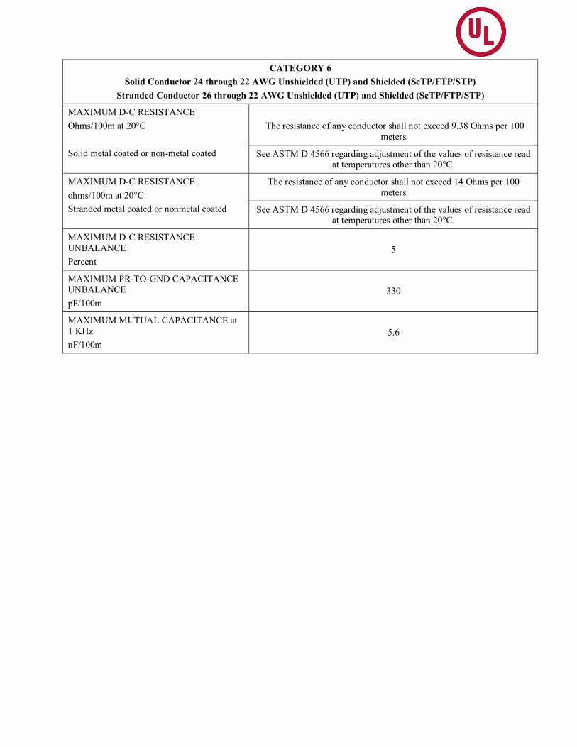
CATEGORY 6 Solid Conductor 24 through 22 AWG Unshielded (UTP) and Shielded (ScTP/FTP/STP)
Stranded Conductor 26 through 22 AWG Unshielded (UTP) and Shielded (ScTP/FTP/STP)
MAXIMUM D-C RESISTANCE Ohms/100m at 20°C Solid metal coated or non-metal coated
The resistance of any conductor shall not exceed 9.38 Ohms per 100
meters
See ASTM D 4566 regarding adjustment of the values of resistance read at temperatures other than 20°C.
MAXIMUM D-C RESISTANCE ohms/100m at 20°C Stranded metal coated or nonmetal coated
The resistance of any conductor shall not exceed 14 Ohms per 100 meters
See ASTM D 4566 regarding adjustment of the values of resistance read at temperatures other than 20°C.
MAXIMUM D-C RESISTANCE UNBALANCE Percent
5
MAXIMUM PR-TO-GND CAPACITANCE UNBALANCE pF/100m
330
MAXIMUM MUTUAL CAPACITANCE at 1 KHz nF/100m
5.6

CATEGORY 6 Table Continued
MAXIMUM INSERTION (ATTENTUATION) LOSS FOR ANY PAIR (IL) dB/100m at 20°C
De-rating factor of 1.2 is applied to solid conductor IL formula above for 26 through 22 AWG stranded conductor cables.
For solid conductor UTP cable elevated temperature testing: Limit is to be increased by 8 percent for measurements at 40°C and 24 percent for measurements at 60°C as applied to the solid conductor IL formula.
For solid conductor ScTP/FTP/STP cable elevated temperature testing: Limit is to be increased by 4 percent for measurements at 40°C and 8 percent for measurements at 60°C as applied to the solid conductor IL formula.
For UTP stranded conductor cable elevated temperature testing: Limit is to be increased by 8 percent for measurements at 40°C and 24 percent for measurements at 60°C as applied to the stranded conductor IL formula.
For ScTP/FTP/STP stranded conductor cable elevated temperature testing: Limit is to be increased by 4 percent for measurements at 40°C and 8 percent for measurements at 60°C as applied to the stranded conductor IL formula.
1.0 f MHz 250.0: IL f 1.808(f) 1/2 + 0.017(f) + 0.200/(f) 1/2 (Solid conductor) 1.0 f MHz 250.0: IL f 1.2 x Insertion loss for solid conductor (stranded conductor)
Solid 24 through 22 AWG
Stranded 22 through 26 AWG
These discrete values are only for formula cross- reference checking. Use swept frequency for limit calculation
1.0 MHz 4.0 8.0 10.0 16.0 20.0 25.0 31.25 62.5 100.0 200.0 250.0
2.0 3.8 5.3 6.0 7.6 8.5 9.5 10.7 15.4 19.8 29.0 32.9
2.4 4.5 6.4 7.1 9.1 10.2 11.4 12.8 18.5 23.8 34.8 39.4

CATEGORY 6 Table Continued
MINIMUM WORST-PAIR NEAR-END CROSSTALK (NEXT) dB at 20°C for a minimum length of 100 meters of any pair combination
1.0 f MHz 250.0: NEXT f 44.3 - 15 log10(f/100)
1.0 MHz 4.0 8.0 10.0 16.0 20.0 25.0 31.25 62.5 100.0 200.0 250.0
74.3 65.3 60.8 59.3 56.2 54.8 53.3 51.9 47.4 44.3 39.8 38.3
These discrete values are only for formula cross reference checking. Use swept frequency for limit calculation.
Hybrid/bundled cables are to comply with the Power Sum NEXT loss requirements stated for Category 6.
MINIMUM POWER SUM NEAR-END CROSSTALK (PSNEXT) dB Per ASTM D 4566 FEXT Measurement Procedure – The Power Sum Near-End Crosstalk (PSNEXT) limits are to be calculated for uncorrelated disturbing pairs using the individual pair-to-pair crosstalk measurements at all of the measurement frequencies
1.0 f MHz 250.0: PSNEXT f 42.3 - 15 log10(f/100)
1.0 MHz 4.0 8.0 10.0 16.0 20.0 25.0 31.25 62.5 100.0 200.0 250.0
72.3 63.3 58.8 57.3 54.2 52.8 51.3 49.9 45.4 42.3 37.8 36.3
These discrete values are only for formula cross reference checking. Use swept frequency for limit calculation.

CATEGORY 6 Table Continued
MINIMUM ATTENUATION-TO-CROSSTALK RATIO FAR (ACRF) [Formally designated EQUAL LEVEL FAR-END CROSSTALK (ELFEXT)] dB Per ASTM D 4566 FEXT Measurement Procedure – ELFEXT is the difference between the measured Far-End Crosstalk (FEXT) and the measured attenuation of the disturbed pair at all of the measurement frequencies
1.0 f MHz 250.0: ACRF f 27.8 - 20 log10(f/100)
1.0 MHz 4.0 8.0 10.0 16.0 20.0 25.0 31.25 62.5 100.0 200.0 250.0
67.8 55.8 49.7 47.8 43.7 41.8 39.8 37.9 31.9 27.8 21.8 19.8
These discrete values are only for formula cross-reference checking. Use swept frequency for limit calculation.
MINIMUM POWER SUM ATTENUATION-TO-CROSSTALK RATIO FAR (PSACRF) [Formally designated POWER SUM EQUAL LEVEL FAR-END CROSSTALK (PSELFEXT)] dB/100m Measurement Precaution – For accurate and consistent results, use a 100-meter unreeled length and maintain wire polarity (tip and ring).
1.0 f MHz 250.0: PSACRF f 24.8 - 20 log10(f/100)
1.0 MHz 4.0 8.0 10.0 16.0 20.0 25.0 31.25 62.5 100.0 200.0 250.0
64.8 52.8 46.7 44.8 40.7 38.8 36.8 34.9 28.9 24.8 18.8 16.8
These discrete values are only for formula cross-reference checking. Use swept frequency for limit calculation.
MINIMUM RETURN LOSS (RL) dB
1.0 f MHz 10.0: RL 20 + 5.0 log 10(f) 10.0 f MHz 20.0: RL 25 (SOLID CONDUCTOR) 20.0 f MHz 250.0: RL 25 - 7.0 log10(f/20)
1.0 f MHz 10.0: RL 20 + 5. 0 log10(f) 10.0 f MHz 20.0: RL 25 (STRANDED CONDUCTOR) 20.0 f MHz 250.0: RL 25 – 8.6 log10(f/20)
CATEGORY 6 Table Continued
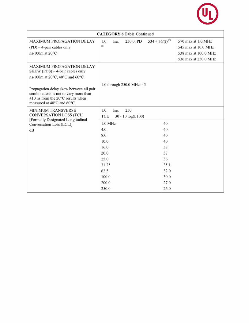
MAXIMUM PROPAGATION DELAY (PD) – 4-pair cables only ns/100m at 20°C
1.0 f MHz 250.0: PD 534 + 36 /(f)1/2 =
570 max at 1.0 MHz 545 max at 10.0 MHz 538 max at 100.0 MHz 536 max at 250.0 MHz
MAXIMUM PROPAGATION DELAY SKEW (PDS) – 4-pair cables only ns/100m at 20°C, 40°C and 60°C. Propagation delay skew between all pair combinations is not to vary more than ±10 ns from the 20°C results when measured at 40°C and 60°C.
1.0 through 250.0 MHz: 45
MINIMUM TRANSVERSE CONVERSATION LOSS (TCL) [Formally Designated Longitudinal Conversation Loss (LCL)] dB
1.0 f MHz 250 TCL 30 - 10 log(f/100)
1.0 MHz 4.0 8.0 10.0 16.0 20.0 25.0 31.25 62.5 100.0 200.0 250.0
40 40 40 40 38 37 36 35.1 32.0 30.0 27.0 26.0
CATEGORY 6 Table Continued
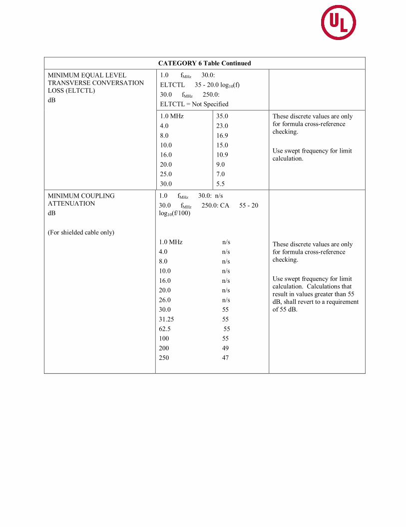
MINIMUM EQUAL LEVEL TRANSVERSE CONVERSATION LOSS (ELTCTL) dB
1.0 f MHz 30.0: ELTCTL 35 - 20.0 log10(f) 30.0 f MHz 250.0: ELTCTL = Not Specified
1.0 MHz 4.0 8.0 10.0 16.0 20.0 25.0 30.0
35.0 23.0 16.9 15.0 10.9 9.0 7.0 5.5
These discrete values are only for formula cross-reference checking. Use swept frequency for limit calculation.
MINIMUM COUPLING ATTENUATION dB (For shielded cable only)
1.0 f MHz 30.0: n/s 30.0 f MHz 250.0: CA 55 - 20 log10(f/100) 1.0 MHz n/s 4.0 n/s 8.0 n/s 10.0 n/s 16.0 n/s 20.0 n/s 26.0 n/s 30.0 55 31.25 55 62.5 55 100 55 200 49 250 47
These discrete values are only for formula cross-reference checking. Use swept frequency for limit calculation. Calculations that result in values greater than 55 dB, shall revert to a requirement of 55 dB.

CATEGORY 6 Table Continued
MAXIMUM SURFACE TRANSFER IMPEDANCE (STI) m/meter (For shielded cable only)
1.0 f MHz 100.0: Z Tcable 10f
1.0 MHz: 50 4.0 50 8.0 80 10.0 100 16.0 160 20.0 200 25.0 250 31.25 312.5 62.5 625 100.0 1000
These discrete values are only for formula cross-reference checking. Use swept frequency for limit calculation.

Category 6A
Solid Conductor 24 through 22 AWG Unshielded (UTP) and Shielded (ScTP/FTP/STP) Stranded Conductor 26 through 22 AWG Unshielded (UTP) and Shielded (ScTP/FTP/STP)
Insertion Loss ≤ 1.82 √f + 0.0091f + 0.25/√f dB (Solid conductor) Insertion Loss ≤ 1.2 x Insertion loss for solid conductor (stranded conductor)
1) For elevated temperature testing of UTP solid & stranded conductor cable the Limit is to be increased by 8 percent for measurements at 40°C and 24 percent for measurements at 60°C as applied to the above applicable IL formula;
For elevated temperature testing of ScTP/FTP/STP solid & stranded conductor cable the Limit is to be increased by 4 percent for measurements at 40°C and 8 percent for measurements at
60°C as applied to the above applicable IL formula; Pair to Pair Near End Crosstalk Loss (NEXT) -44.3-15log(f/100) dB Power Sum NEXT (PSNEXT) -42.3-15log(f/100) dB Attenuation to Crosstalk Ratio Far (ACRF) [a.k.a ELFEXT] -27.8-20log(f/100) dB Power Sum Attenuation to Crosstalk Ratio Far (PSACRF) [a.k.a PSELFEXT] -24.8-20log(f/100) dB Return Loss (Solid Conductor Cable): 1 f < 10 20+5log(f) dB, 10 f < 20 25 dB, 20 f 500 = 25-7Log(f/20) dB
Return Loss (Stranded Conductor Cable): 1 f < 10 20+5log(f) dB, 10 f < 20 25 dB, 20 f 500 = 25-8.6Log(f/20) dB
MHz Insertion Loss dB
NEXT dB
PSNEXT dB
ACRF dB
PSACRF dB
RL dB
RL (Stranded Conductor Cable)
dB 0.772 ---- ---- ---- ---- ---- ---- ----
1 2.1 74.3 72.3 67.8 64.8 20.0 20.0 4 3.8 65.3 63.3 55.8 52.8 23.0 23.0 8 5.3 60.8 58.8 49.7 46.7 24.5 24.5
10 5.9 59.3 57.3 47.8 44.8 25.0 25.0 16 7.5 56.2 54.2 43.7 40.7 25.0 25.0 20 8.4 54.8 52.8 41.8 38.8 25.0 25.0 25 9.4 53.3 51.3 39.8 36.8 24.3 24.2
31.25 10.5 51.9 49.9 37.9 34.9 23.6 23.3 62.5 15.0 47.4 45.4 31.9 28.9 21.5 20.7 100 19.1 44.3 42.3 27.8 24.8 20.1 19.0 200 27.6 39.8 37.8 21.8 18.8 18.0 16.4 250 31.1 38.3 36.3 19.8 16.8 17.3 15.6 300 34.3 37.1 35.1 18.3 15.3 16.8 14.9 400 40.1 35.3 33.3 15.8 12.8 15.9 13.8 500 45.3 33.8 31.8 13.8 10.8 15.2 13.0

Category 6A Table Continued
Propagation Delay: 534 + 36/√f ns/100m Propagation Delay Skew – For all frequencies from 1 to 500 MHz shall not exceed 45 ns at 20C, 40C and 60C. Propagation Delay Skew between all pairs shall not vary more than ±10 ns Transverse Conversion Loss (TCL): -30-10log(f/100) dB Equal Level Transverse Conversion Transfer Loss (ELTCTL): 1 f < 30 -35-20log(f/100) dB DC Resistance Unbalance – The resistance unbalanced between the two conductors of any cable shall not exceed 4 %. DC Resistance (solid metal-coated or non-metal coated) - The resistance of any conductor shall not exceed 9.38 Ohms per 100 meters. DC Resistance (stranded metal-coated or non-metal coated) - The resistance of any conductor shall not exceed 14 Ohms per 100 meters. Mutual Capacitance (Maximum) – 5.6 nF per 100 meter Capacitance Unbalanced (Maximum) – 330 nF per 100 meter Coupling Attenuation (Maximum – for shielded cable only) 1.0 f MHz 30.0: n/s 30.0 f MHz 500.0: CA 55 - 20 log10(f/100)
Surface Transfer Impedance (STI) (Minimum) - 1.0 f MHz 100.0: Z Tcable = 10f (Calculations that result in STI values less than 50 m/m shall revert to a requirement of 50 m/m minimum) Power Sum Alien NEXT (PSANEXT) -62.5-15log(f/100) dB Power Sum Alien Attenuation to Crosstalk Ratio Far (PSAACRF) -38.2-20log(f/100) dB
n/s = Not Specified MHz Propagation
Delay ns
Propagation Delay Skew
ns
TCL dB
ELTCTL dB
Coupling Attenuation
dB
STI m/m
PSANEXT dB
PSAACRF dB
0.772 n/s n/s n/s n/s n/s n/s n/s n/s 1 570 45 40.0 35.0 n/s 50 67.0 67.0 4 552 45 40.0 23.0 n/s 50 67.0 66.2 8 547 45 40.0 16.9 n/s 50 67.0 60.1
10 545 45 40.0 15.0 n/s 100 67.0 58.2 16 543 45 38.0 10.9 n/s 160 67.0 54.1 20 542 45 37.0 9.0 n/s 200 67.0 52.2 25 541 45 36.0 7.0 n/s 250 67.0 50.2
31.25 540 45 35.1 5.5 55.0 312.5 67.0 48.3 62.5 539 45 32.0 n/s 55.0 625 65.6 42.3 100 538 45 30.0 n/s 55.0 1000 62.5 38.2 200 537 45 27.0 n/s 49.0 n/s 58.0 32.2 250 536 45 26.0 n/s 47.0 n/s 56.5 30.2 300 536 45 25.2 n/s 45.5 n/s 55.3 28.7 400 536 45 24.0 n/s 43.0 n/s 53.5 26.2 500 536 45 23.0 n/s 41.0 n/s 52.0 24.2

Category 8
The cable shall consist of solid conductor 24 through 22 AWG around a shield (ScTP/FTP/STP) under an overall jacket whose transmission characteristics are specified from 1 to 2000 MHz. A length of 30 meters (98.43 feet) shall be used for all tests except Coupling Attenuation. A length of 100 meters (328 feet) shall be used for Coupling Attenuation.
Insertion Loss: ≤ 0.540 √f + 0.00150f + 0.075/√f dB (Solid conductor)
For elevated temperature testing of UTP solid & stranded conductor cable the Limit is to be increased by 0.2 percent increase per °C for the frequency range 1 MHz to 2000MHz applied to the above
applicable IL formula Pair to Pair Near End Crosstalk Loss (NEXT): - 45.3 - 15log(f/100) dB Power Sum NEXT (PSNEXT): -42.3 - 15log(f/100) dB Attenuation to Crosstalk Ratio Far (ACRF) [a.k.a ELFEXT]: -39 - 20log(f/100) dB Power Sum Attenuation to Crosstalk Ratio Far (PSACRF) [a.k.a PSELFEXT]: -36 - 20log(f/100)
dB Return Loss: 1 f < 10 20+5log(f) dB; 10 f < 40 25 dB; 40 f ≤ 2000 25 - 7Log(f/40) dB
The information in the Table below is provided for information only.
MHz Insertion Loss dB
NEXT dB
PSNEXT dB
ACRF dB
PSACRF dB
RL dB
1 2.0 75.3 72.3 75.0 76.0 20.0 4 2.0 66.3 63.3 67.0 64.0 23.0 8 2.0 61.8 58.8 60.9 57.9 24.5
10 2.0 60.3 57.3 59.0 56.0 25.0 16 2.2 57.2 54.2 54.9 51.9 25.0 20 2.5 55.8 52.8 53.0 50.0 25.0 25 2.8 54.3 51.3 51.0 48.0 25.0
31.25 3.1 52.9 49.9 49.1 46.1 25.0 62.5 4.4 48.4 45.4 43.1 40.1 23.6 100 5.6 45.3 42.3 39.0 36.0 22.2 200 7.9 40.8 37.8 33.0 30.0 20.1 250 8.9 39.3 36.3 31.0 28.0 19.4 300 9.8 38.1 35.1 29.5 26.5 18.9 400 11.4 36.3 33.3 27.0 24.0 18.0 500 12.8 34.8 31.8 25.0 22.0 17.3 600 14.1 33.6 30.6 23.4 20.4 16.8 1000 18.6 30.3 27.3 19.0 16.0 15.2 1500 23.2 27.7 24.7 15.5 12.5 14.0 2000 27.2 25.8 22.8 13.0 10.0 13.1

Category 8 Table Continued
Propagation Delay: 1.0 f MHz 2000 = 160 + 11/√f ns/30m Propagation Delay Skew – For all frequencies from 1 to 2000 MHz shall not exceed 13.5/30m ns at 20°C,
40°C and 60°C. Propagation Delay Skew between all pairs shall not vary more than ±3 ns from the measured value at 20°C when measured at 40°C and 60°C.
Transverse Conversion Loss (TCL): -20 - 15log(f/100) dB
Equal Level Transverse Conversion Transfer Loss (ELTCTL): 1 f ≤ 56 -40 - 20log(f) dB & 56 < f ≤ 2000 = 5dB for
DC Resistance Unbalance – The resistance unbalanced between the two conductors of any cable shall not exceed 4 %. DC Resistance Unbalance Between Pairs – The resistance unbalanced between the two conductors of any
cable shall not exceed 5 %. DC Resistance (solid metal-coated or non-metal coated) - The resistance of any conductor shall
not exceed 2.4 Ohms per 30 meters. Mutual Capacitance (Maximum) – Not specified Capacitance Unbalanced : Pair to ground (Maximum) – 99 pF per 30 meter
The information in the Table below is provided for information only. MHz Propagation
Delay ns
Propagation Delay Skew
ns
TCL (unshielded)
dB
TCL (shielded)
dB
ELTCTL (unshielded)
dB
ELTCTL (shielded)
dB 1 171.0 13.5 40.0 40.0 47.2 40.0 4 165.5 13.5 40.0 40.0 35.2 28.0 8 163.9 13.5 40.0 36.5 29.1 21.9 10 163.5 13.5 40.0 35.0 27.2 20.0 16 162.8 13.5 39.9 31.9 23.1 15.9 20 162.5 13.5 38.5 30.5 21.2 14.0 25 162.2 13.5 37.0 29.0 19.2 12.0
31.25 162.0 13.5 35.6 27.6 17.3 10.1 62.5 161.4 13.5 31.1 23.1 11.3 5.0 100 161.1 13.5 28.0 20.0 7.2 5.0 200 160.8 13.5 23.5 15.5 5.0 5.0 250 160.7 13.5 22.0 14.0 5.0 5.0 300 160.6 13.5 20.8 12.8 5.0 5.0 400 160.6 13.5 19.0 11.0 5.0 5.0 500 160.5 13.5 17.5 9.5 5.0 5.0 600 160.4 13.5 16.3 8.3 5.0 5.0
1000 160.3 13.5 13.0 7.0 5.0 5.0 1500 160.3 13.5 10.4 7.0 5.0 5.0 2000 160.2 13.5 8.5 7.0 5.0 5.0

Category 8 (Table Continued)
• Coupling Attenuation (Maximum) 1.0 ≤ fMHz ≤30.0 = n/s; 30.0 ≤ fMHz ≤ 100.0 = 55; 100.0 ≤fMHz ≤ 2000.0 = 55 - 20 log10(f/100) • Surface Transfer Impedance (STI) (Minimum) - 1.0 ≤ fMHz ≤ 2000 = ZTcable = 10f (Calculations that result in STI values less than 50 mΩ/m shall revert to a requirement of 50 mΩ/m Minimum – using tri-axial method per IEC62153-4-3) • Power Sum Alien NEXT (PSANEXT): 1.0≤fMHz ≤ 2000 = ≥ -87.5-15log(f/100) dB • Power Sum Alien Attenuation to Crosstalk Ratio Far (PSAACRF): 1.0 ≤ fMHz≤ 2000 = ≥ -62.2 -
20log(f/100) dB. n/s = Not Specified
The information in the Table below is provided for information only.
MHz Coupling Attenuation
dB
STI mΩ/m
PSANEXT dB
PSAACRF dB
1 n/s 50 80.0 80.0 4 n/s 50 80.0 80.0 8 n/s 50 80.0 80.0 10 n/s 100 80.0 80.0 16 n/s 160 80.0 78.1 20 n/s 200 80.0 76.2 25 n/s 250 80.0 74.2
31.25 55.0 312.5 80.0 72.3 62.5 55.0 625 80.0 66.3 100 55.0 1000 80.0 62.2 200 49.0 n/s 80.0 56.2 250 47.0 n/s 80.0 54.2 300 45.5 n/s 80.0 52.7 400 43.0 n/s 78.5 50.2 500 41.0 n/s 77.0 48.2 600 39.4 n/s 75.8 46.6
1000 35.0 n/s 72.5 42.2 1500 31.5 n/s 69.9 38.7 2000 29.0 n/s 68.0 36.2

HYBRID CABLE CONSTRUCTION (see construction & marking requirements on Page 8
These cables consist of two or more jacketed members, of the same or different categories, covered with an overall jacket. Specified for Category 3, 5, 5E and 6 cables only.
BUNDLED CABLE CONSTRUCTIONS (see construction & marking requirements on Page 8 (Constructions A and B)
These cables consist of two or more jacketed members, of the same or different categories, bound together by a binder tape or thread, or laid flat and parallel joined by an interconnecting web. Specified for Category 3, 5, 5E and 6 cables only.
Category 3, 5 & 5E hybrid/bundled cables shall comply with the Power Sum NEXT loss requirements for any disturbed pair and all pairs external to that pair's jacket within the cable. In addition, each jacketed member shall comply with the specified performance requirements for that individual member, in addition to the following:
NEXTf = NEXT (0.772) - 15 log10(f/0.772) [Category 3 hybrid/bundled cables]
NEXTf = NEXT (100) - 15 log10(f/100) [Category 5 hybrid/bundled cables]
NEXTf = NEXT (100) - 15 log10(f/100) [Category 5E hybrid/bundled cables]
Using the above formula, the hybrid/bundled Power Sum NEXT loss shall be 3 dB better than the specified pair-to-pair NEXT loss throughout the range of frequencies noted below for the Category. Calculated Power Sum values that are greater than 65 dB shall not be used to determine power sum compliance.
Category 3 Cables (772 kHz through 16.0 MHz)
The PSNEXT value shall be 26.2-15 log10(f/0.772) dB.
Category 5 Cables (772 kHz through 100.0 MHz)
The PSNEXT value shall be 35-15 log10(f/0.772) dB
Category 5E Cables (1.0 MHz through 100.0 MHz)
The PSNEXT value shall be 26.2-15 log10(f/0.772) dB
Category 6 hybrid/bundled cables shall comply with the Category 6 transmission requirements specified in this bulletin. Additionally, hybrid/bundled cables shall comply with the total power sum NEXT loss for any disturbed pair from all pairs internal and external to that pair's jacket within the hybrid/bundled cable, through the range of frequencies noted below for the category, shall not exceed the values using the following formula:
PSNEXT hybrid/bundled, all pairs 41.1 - 15 log (f/100)
Near-end crosstalk (NEXT) measurements shall be determined using the following formula:
NEXT 44.3 - 15 log (f/100)
Category 6 cables (1.0 through 250.0 MHz)
Calculated PSNEXT loss limit that exceeds 65 dB shall revert to a limit of 65 dB.

BACKBONE CABLE CONSTRUCTION (see construction & marking requirements on Page 10 Backbone cables shall meet the transmission performance requirements a specified for 100-Ohm unshielded (UTP) & shielded (ScTP/FTP/STP) twisted pair horizontal Category 3, 5, 5E, 6 and 6A CABLES with the exception to the requirements as specified below. In cases where backbone cables consist of 25-pair groups, PSNEXT shall be determined for each 25 pair binder group. PSNEXT loss requirements shall not be applied between 25 pair binder groups. Insertion Loss (IL) – Elevated temperature testing is not required. Near End Crosstalk (Next) Loss – As shown below:
Performance Category
Frequency (MHz)
Minimum Near End Crosstalk, NEXT (dB)
3 1.0 f MHz 16.0 Not Specified 5 1.0 f MHz 100.0 32 - 15 log (f/100)
5E 1.0 f MHz 100.0 35.3 - 15 log (f/100) 6 1.0 f MHz 250.0 44.3 - 15 log (f/100)
6A 1.0 f MHz 500.0 44.3 - 15 log (f/100) Near End Crosstalk (NEXT) Loss shall be measured for all adjacent 4 pair combinations in accordance with ASTMD4566 for all frequencies as shown above. Multipair backbone cables are evaluated in 4 pair groups. For 25 pair and multiple of 25 pair binder groups, the 25th pair shall comply with all other test parameters when used within any 4 pair group. In the case of multiple 25 pair binder groups, NEXT Loss shall be tested for each 25 pair binder group only without NEXT Loss requirements between binder groups. Power Sum Near End Crosstalk (PSNext) Loss – As shown below:
Performance Category
Frequency (MHz)
Minimum Near End Crosstalk, NEXT (dB)
3 1.0 f MHz 16.0 23 - 15 log (f/16) 5 1.0 f MHz 100.0 32 - 15 log10(f/100)
5E 1.0 f MHz 100.0 32.3 - 15 log (f/100) 6
(For four (4) pr. Cables only)
1.0 f MHz 250.0 42.3 - 15 log (f/100)
6A (For four (4) pr. Cables only)
1.0 f MHz 500.0 42.3 - 15 log (f/100)
In the case of multiple 25 pair binder groups, PSNEXT Loss shall be tested for each 25 pair binder group only without PSNEXT Loss requirements between binder groups.

Attenuation to Crosstalk Far (ACRF) – As shown below:
Performance Category
Frequency (MHz)
Minimum Near End Crosstalk, NEXT (dB)
3 1.0 f MHz 16.0 Not Specified 5 1.0 f MHz 100.0 Not Specified
5E 1.0 f MHz 100.0 23.8 – 20log (f/100) 6 1.0 f MHz 250.0 27.8 – 20log (f/100)
6A 1.0 f MHz 500.0 27.8 - 20log (f/100) Far End Crosstalk (FEXT) Loss shall be measured for all adjacent 4 pair combinations in accordance with ASTMD4566 for all frequencies as shown above. Multi pair backbone cables are evaluated in 4 pair groups. For 25 pair and multiple of 25 pair binder groups, the 25th pair shall comply with all other test parameters when used within any 4 pair group. In the case of multiple 25 pair binder groups, FEXT Loss shall be tested for each 25 pair binder group only without FEXT Loss requirements between binder groups and ACRF shall be calculated subtracting the insertion loss of the disturbed pair of the backbone cable form the FEXT Loss. Power Sum Attenuation to Crosstalk Far (ACRF) – As shown below:
Performance Category
Frequency (MHz)
Minimum Near End Crosstalk, NEXT (dB)
3 1.0 f MHz 16.0 Not Specified 5 1.0 f MHz 100.0 Not Specified
5E 1.0 f MHz 100.0 20.8 – 20log (f/100) 6
(For four (4) pr. Cables only)
1.0 f MHz 250.0 24.8 – 20log (f/100)
6A (For four (4) pr. Cables only)
1.0 f MHz 500.0 24.8 - 20log (f/100)
In the case of multiple 25 pair binder groups, PSFEXT Loss shall be tested for each 25 pair binder group only without PSFEXT Loss requirements between binder groups. Propagation Delay – As shown below:
Performance Category
Frequency (MHz)
Propagation Delay (dB)
3 1.0 f MHz 16.0 Not Specified 5 1.0 f MHz 100.0 Not Specified
5E 1.0 f MHz 100.0 534 + 36/f 6
(For four (4) pr. Cables only)
1.0 f MHz 250.0 534 + 36/f
6A (For four (4) pr. Cables only)
1.0 f MHz 500.0 534 + 36/f
Propagation Delay Skew – As shown below:
Performance Category
Frequency (MHz)
Propagation Delay Skew, (ns)
3 1.0 f MHz 16.0 Not Specified 5 1.0 f MHz 100.0 Not Specified
5E 1.0 f MHz 100.0 45 6
(For four (4) pr. Cables only)
1.0 f MHz 250.0 45
6A (For four (4) pr. Cables only)
1.0 f MHz 500.0 45