subdivision and development servicing bylaw no. 1730, …
TRANSCRIPT

SUBDIVISION AND DEVELOPMENT SERVICING BYLAW NO. 1730, 2000
VOLUME 2
DRAWING STANDARDS

CITY OF WILLIAMS LAKE
SUBDIVISION AND DEVELOPMENT SERVICING BYLAW NO. 1730, 2000
VOLUME 2
DRAWING STANDARDS
THE CITY OF WILLIAMS LAKE SUBDIVISION AND DEVELOPMENT SERVICING BYLAW NO. 1730, 2000
TABLE OF CONTENTS VOLUME 1 - Development Requirements ( Bound Separately ) Sections Section 1 - Title ..........................................................................................1
Section 2 - Interpretation............................................................................ 2
Section 3 - General Provisions................................................................... 6
Section 4 - Servicing Requirements ........................................................ 17
Section 5 - Fees and Charges ................................................................... 18
Section 6 - Insurance Requirements ........................................................ 20
Section 7 - Schedules and Appendices .................................................... 22
Section 8 - Enactment............................................................................... 24 Schedules Schedule A - Service Levels
Schedule B - Regulations, Standards and Specifications for the Design of Site Grading
Schedule C - Regulations, Standards and Specifications for the Design of Highways, Lanes and Walkways
Schedule D - Regulations, Standards and Specifications for the Design of Curbs and Gutters, Sidewalks and Boulevards
Schedule E - Regulations, Standards and Specifications for the Design of Water Systems
Schedule F - Regulations, Standards and Specifications for the Design of Sanitary Sewers
Schedule G - Regulations, Standards and Specifications for the Design of Drainage Systems

(ii)
THE CITY OF WILLIAMS LAKE
SUBDIVISION AND DEVELOPMENT SERVICING BYLAW NO. 1730, 2000
TABLE OF CONTENTS cont.
Schedule H - Regulations, Standards and Specifications for the Design of Street Lighting
Schedule I - Regulations, Standards and Specifications for the Installation of Electrical, Communications Wiring, Cablevision and Gas Distribution System
VOLUME 1 - Development Requirements Cont. ( Bound Separately ) Appendices
Appendix 1 - Confirmation of Commitment by Owner Confirmation of Professional Assurance by Civil Engineer Confirmation of Professional Assurance by Geotechnical Engineer
Appendix 2 - Sample Standard Statutory Right-of-Way Document Restoration Statement of Release
Appendix 3 - Substantial Completion Certificate Construction Completion Certificate Final Acceptance Certificate
Appendix 4 - Sample Subdivision Servicing Agreement VOLUME 2 - Drawing Standards Schedules
Schedule J - Standards for the Preparation of Design and Construction Record Drawings
Appendices Appendix 5 - Sample City of Williams Lake – Service History Sheet
Appendix 6 - City of Williams Lake Digital Drawing Standards

(iii)
VOLUME 3 - Specifications and Standard Drawings ( Bound Separately ) Sections Section 2 - Interpretation.................................................................................. 1
Schedules Schedule K - Specifications for the Construction of Works and Infrastructure
Designed Under Schedules B through I
Schedule L - Standard Drawings Index and Standard Drawings
Appendices Appendix 7 - City of Williams Lake – Approved Product List

SCHEDULE J
STANDARDS FOR THE PREPARATION OF DESIGN AND CONSTRUCTION RECORD DRAWINGS
I, WAYNE K. THIESSEN, MUNICIPAL CLERK OF THE
CITY OF WILLIAMS LAKE, DO HEREBY CERTIFY THIS TO BE SCHEDULE “J” TO BYLAW NO. 1730.
"original signed by"
_________________________________________________MUNICIPAL CLERK

J-1
SCHEDULE J
STANDARDS FOR THE PREPARATION OF DESIGN AND CONSTRUCTION RECORD DRAWINGS
J-1.0 GENERAL REQUIREMENTS
These requirements pertain to the preparation of drawings for: all works constructed or installed within City Property, dedicated road allowance, statutory right-of-way or to be maintained by the City.
This Schedule shall be read with Schedules B through I – RECORD DOCUMENTATION
requirements.
Drawing production shall meet the requirements of the City of Williams Lake DIGITAL DRAWING STANDARDS, current version. A copy of the DIGITAL DRAWING STANDARDS are attached in Appendix 6. They are included for convenience only and do not form part of this Bylaw. The DIGITAL DRAWING STANDARDS are subject to change and the Design Engineer shall ensure that the current version of the Standards and associated digital files are used.
Where no standard is defined or referenced in this schedule for the preparation of a drawing to portray a particular service, structure, or other item; instructions and requirements shall be obtained from the Director of Planning and Engineering.
J-2.0 DOCUMENT AND DRAWING SUBMISSIONS
The Design Engineer shall submit Design Drawings and Construction Record Drawings as specified in this schedule to the Director of Planning and Engineering for approval.
J-2.01 Design Drawing Submissions
.1 For Design Drawing Approval:
3 paper copies, 1 returned AS APPROVED or FOR REVISION.
.2 For Construction Drawings, after design approval received from the Director of
Planning and Engineering:
3 paper copies marked FOR CONSTRUCTION are to be submitted prior to commencing construction.

J-2
J-2.02 Record Documentation Submissions
Prior to acceptance of the Works, the Design Engineer shall submit 3 bound copies of Construction Documentation to the Director of Planning and Engineering. Construction Documentation shall fully indicate the as-constructed aspects of each system as well as all required operation and maintenance information. All “record documentation” remains the property of the City of Williams Lake after its acceptance. All “record documentation” prepared / held by the City is subject to copyright. As a minimum, Construction Documentation shall include the following: .1 all items specified in Schedules B-I under RECORD DOCUMENTATION; .2 complete set of Construction Record Drawings at the same scale and in the same
format as the construction drawings; The record drawings submitted to the City will show the date of construction
completion and the designation CONSTRUCTION RECORD DRAWINGS in the revision box.
Check Copy Two sets of paper prints to be submitted to the Director of Planning
and Engineering to be checked for completeness and compliance to these standards and one set of prints will be returned AS APPROVED or FOR REVISION.
Final Submissions One set Mylar original record drawings.
One set Paper prints signed and sealed by Design Engineer. .3 Construction Record AutoCAD files saved in the format specified in the Digital
Drawing Standards. .4 copies of all test reports and results; .5 all shop drawings; .6 a list of contractors and major subcontractors by work item; .7 Operating and Maintenance Manuals; and .8 A completed City of Williams Lake – PROPERTY HISTORY SHEET for each new
lot created or serviced by the works (a sample sheet is included in Appendix 5).

J-3
J-3.0 PREPARATION OF DRAWING The following standards apply to both design and record drawings. All symbols to be used on the drawings to be as per the DIGITAL DRAWING
STANDARDS. Combine water, sanitary and storm on one drawing as feasible. J-3.01 Drawing Standards
Size: A1 (594 mm x 841 mm) or 24” x 36” Material: 3 mil mylar polyester film Format: Half plan and half profile with plan at top of sheet Lettering: Appendix 6, Section 3.4 Profile Grid: 10 mm x 10 mm Title Block: See Sample Drawings STD 1 and STD 2
J-3.02 Title Block .1 Design Engineers must use the City of Williams Lake A-1 standard Title Block. .2 Design Engineers name, address and phone number are to be on all drawings.
.3 A sample of a prepared plan/profile sheet, and an AutoCAD disk of the Standard Title Block shell may be obtained by contacting the City of Williams Lake.
J-3.03 Sheet Layout .1 Maintain a minimum clearance of 10 mm from all borders. .2 Place north arrow close to the top right hand side of the sheet whenever possible. .3 North arrow shall point either towards the top of the page or towards the left hand
edge of the page. The north arrow may point not more than 60° to the right hand side of the page.
.4 Show distances and location dimensions in metres and to 3 decimal places.
.5 Show pipe sizes in mm as per A.S.T.M. specifications using 1" = 25 mm.
.6 Existing imperial dimensions except for pipe sizes are to be soft converted using the
factor:
1 inch (1") = 25.4 cm; and 1 foot (1') = 0.3048 m.

J-4
J-3.04 Scales Use metric scales: Horizontal Scale 1:500
Vertical Scale 1:50
The Director of Planning and Engineering may request drawings at different scales. Other drawing scales must be approved by the Director of Planning and Engineering. J-3.05 General Notes
.1 “DESIGN” denotes those improvements to be installed on the project submitted. .2 “EXISTING” denotes utility improvements at the design or record drawing stage
are existing. .3 For Projects in existing roads, rights of way and easements, the drawings shall
show all existing improvements such as, but not limited to:
.1 watermains, fittings, service connections, appurtenances
.2 hydrants
.3 valves (gate, butterfly, air, gas)
.4 blowoff, air inlet
.5 sanitary sewers and service connections
.6 clean-outs
.7 manholes (drainage, sewer, Telus, BC Hydro)
.8 inspection chambers (sewer, storm)
.9 storm sewers and service connections
.10 catch basins and lawn drains
.11 ditches and natural watercourses
.12 driveway culverts (and sizes)
.13 utility poles and guy wires
.14 street lights
.15 traffic signals
.16 service/junction boxes
.17 underground cables (e.g. electrical, telephone and cablevision)
.18 gas lines
.19 curbs and gutters
.20 boulevards
.21 sidewalks
.22 traffic islands
.23 edges of pavement
.24 trees
.25 covenant areas

J-5
.4 All construction or alternations are to be shown on drawings distinguished from the existing items by different line weights as per the DIGITAL DRAWING STANDARDS.
.5 Notes pertaining to the construction or alterations are to be shown on the drawing. .6 All stationing, elevations, coordinates are to be in metres and indicated to the
nearest 0.001 metres. The dimensions and offsets for service connections, wye etc. are to be shown to the nearest 0.1 metres.
.7 A key plan is required to indicate the location and the scope of the works. .8 In the CAD database, all features are to be drawn at a 1:1 scale. .9 All information will be audited to ensure accuracy, completeness and compliance
with these specifications.
J-3.06 Control and Baselines .1 All utility and property information is to be related to the City of Williams Lake
Grid System (CWLGS). .2 The vertical datum is the Canadian Vertical Datum of 1928 (CVD28) and
elevations are geodetic. .3 All baselines are to be tied to property corners (stationing for all IP’s found) and
shown on the drawings. .4 Offsets are to be shown to both sides of the road allowance or to one side with the
road right of way width annotated.
J-3.07 Stationing .1 Stations will be at 20 metre (maximum) intervals or less when higher level of detail
is required (e.g. road rehabilitation, special construction). .2 Stationing of intersections and starting points are to be related to legal corner(s).
J-3.08 Plan View .1 Show utility and utility access R.O.W.'s. .2 Show control station monuments with identification number. .3 The PLAN VIEW should not be fragmented or broken due to slight curves in the
road right-of-way.

J-6
.4 If using co-ordinates for layouts, calculate and plot distances at ground level.
.5 Show the legal layout of roads and properties, with all legal descriptions (lots and
plan numbers) and dimensions. Also show existing civic addresses and all registered statutory rights of way, covenants and easements.
.6 All lot dimensions shall be given in metres and to three (3) decimal places.
.7 All offsets of mains, existing and design will be referenced to and along property lines.
.8 The names of streets are to be indicated outside of the road boundaries. Road
widths are to be annotated. Temporary names (e.g. A, B, C) will not be accepted, except for new subdivisions where the City has not yet named the streets.
.9 An offset from property corners must be shown for all service connections. If the
connection is not perpendicular to the main, the location of each bend is to be shown. The invert elevation and depth at property line from existing ground level are to be shown. Where there are existing connections, the field measured inverts are to be shown.
.10 Coordinates, elevations and two dimensions from property corners are required to
show the location for all manholes, valves, tees, hydrants, stubs, catch basins, lawn drains, clean-outs, inspection chambers, fittings, bends in pipes, etc. Locations of all test holes, boreholes, etc. must be coordinated on the City of Williams Lake Grid System (CWLGS) projection.
J-3.09 Profile .1 The profile and related data are shown on the bottom half of the sheet. Establish 0+00
station on an accented vertical grid line. .2 The original groundline (centreline) and related data prior to construction should be
shown, along with date surveyed. .3 All grade changes are to show stationing or ties to lot corners. City of Williams
Lake Grid System (CWLGS) coordinates and geodetic elevations are to be shown for grade changes.
.4 Profiles must be shown for all sanitary (for pipes greater than 100mm diameter) and
storm services (for pipes greater than 200mm diameter) except where the installation of connections from an existing main is the only work performed.
.5 The profile shall be shown at true centreline length and projected above to the PLAN
VIEW in as close a relationship as possible. .6 Show as constructed centreline for streets and lanes and date constructed.

J-7
.7 Show centreline percent grade to two (2) decimal places, together with the following information on vertical curves:
.1 the stationing and elevations of B.C., E.C., and V.P.I.; .2 the algebraic difference of grades in percent (A); .3 the curve rate constant (K); .4 the length of vertical curve (L); .5 the stationing and elevation of the low spot of sag curves or high point of
crest curves; and .6 on super elevated curves and crossfall sections, percent crossfall, transition
length and crown shall be noted. .8 Show profiles of invert of pipes for sanitary, storm, and water mains as well as length,
size, type, grade, and class of pipe (eg. 75 m - 200 mm SAN SDR 35 PVC). .9 Show manholes with rim elevations, and invert elevations at both inlet and outlet. .10 Crown of pipes shall be shown at all locations where there is the possibility of
conflicts with other utilities. .11 Show location type and elevation of all crossing utilities. .12 Elevations are placed at the right and left hand side of the profile and repeated when
there is a break in the profile. .13 Elevations are to be shown at every even metre graduation and placed on the heavy
accented line.

APPENDIX 5
City of Williams Lake Property History Sheet

CITY OF WILLIAMS LAKE SERVICE HISTORY SHEET FOLIO: PID# LEGAL: LOT(S) BLOCK DL PLAN ADDRESS: SANITARY CONNECTION: SIZE mm MATERIAL INV. CONNECTED WATER CONNECTION: SIZE mm MATERIAL METER CONNECTED STORM CONNECTION: SIZE mm MATERIAL INV. CONNECTED Cash Receipt No=s: WATER SANITARY STORM CURB FROM PROPERTY LINE PAVEMENT WIDTH BC HYDRO UNDERGROUND CONNECTION TELUS UNDERGROUND CONNECTION Information Sheets: Date Installed:
Date Connected:
Comments:
THE INFORMATION CONTAINED HEREIN IS FOR INTERNAL USE ONLY NOT TO BE RELIED UPON UNLESS CONFIRMED BY SITE INSPECTION AND/OR INVESTIGATION
DESIGN ENGINEER TO OBTAIN CARD STOCK COPY FROM THE CITY FOR SUBMISSION
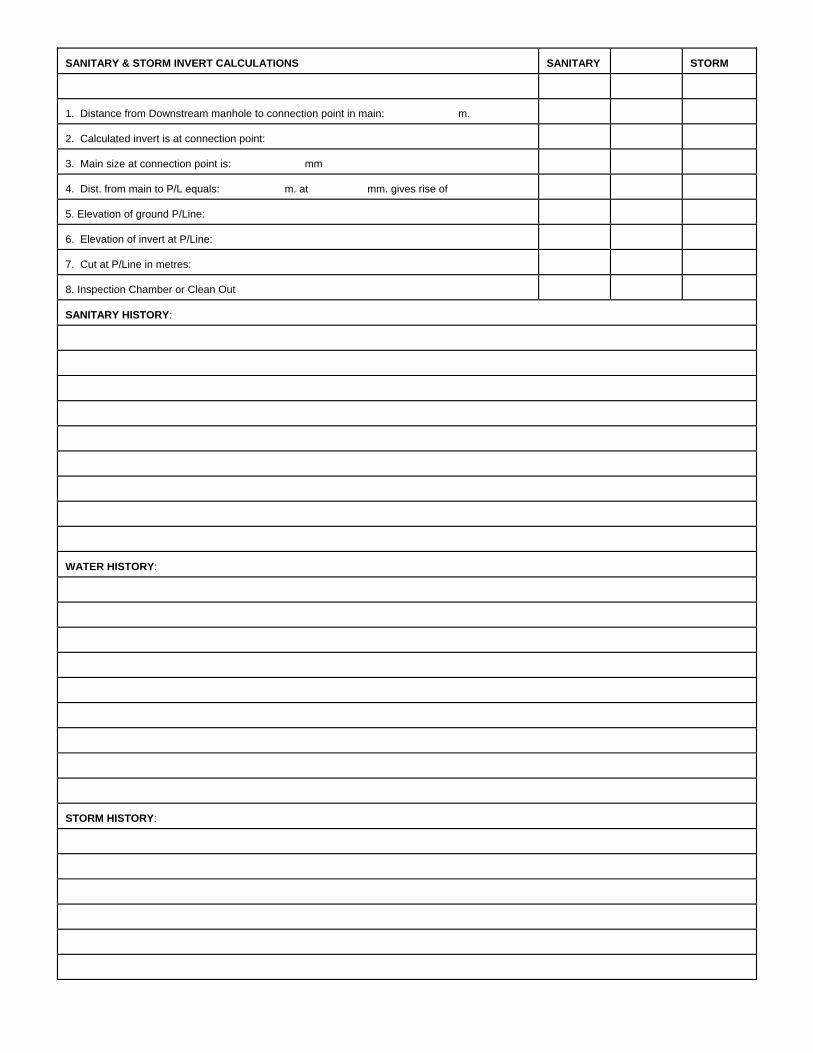
SANITARY & STORM INVERT CALCULATIONS
SANITARY
STORM
1. Distance from Downstream manhole to connection point in main: m.
2. Calculated invert is at connection point:
3. Main size at connection point is: mm
4. Dist. from main to P/L equals: m. at mm. gives rise of
5. Elevation of ground P/Line:
6. Elevation of invert at P/Line:
7. Cut at P/Line in metres:
8. Inspection Chamber or Clean Out
SANITARY HISTORY: WATER HISTORY: STORM HISTORY:

APPENDIX 6
City of Williams Lake Digital Drawing Standards

CITY OF WILLIAMS LAKE
DIGITAL DRAWING
STANDARDS
VERSION 1.1
FEBRUARY 2000

1.0 INTRODUCTION These standards were designed for developers, consultants and land surveyors in the preparation of cadastral and topographic mapping, design, construction, and record drawings required by the City of Williams Lake. These standards were formulated to achieve these objectives: C To record and communicate comprehensive, accurate and up-to-date information
about Williams Lake=s infrastructure. C To establish standards and guidelines for the development of computer generated
record drawings. C To provide structure for developing infrastructure databases. C To improve operational effectiveness and efficiency in information transfer from
Computer Assisted Drafting and Design (Autocad) to future Geographic Information System.
C These standards will define utilities in three dimensions, that is, location of features in the three axes (X, Y, Z).
C To reduce inconsistencies among municipal and provincial digital plan standards. C To promote and facilitate data sharing and exchange with individuals, companies,
agencies and governments. C To reduce accidents and damage to underground utilities by moving to the BC One
Call System in the future. These standards are applicable for drawings with scales ranging from 1:200, 1:250, 1:500, 1:1000, 1:2000, 1:2500, 1:5000, 1:10,000 only except for details. These standards will be revised periodically. This edition is deemed AVersion 1.1@. Any suggestions or recommendations are welcome and appreciated and should be directed to the Engineering Technologist at: City of Williams Lake Engineering Department 450 Mart Street Williams Lake, BC V2G 1N3 Phone: (250)392-2311 Fax: (250)392-4408
-1- 2.0 GENERAL STANDARDS

- 2 -
2.1 Cadastral Compilation The City of Williams Lake is using and maintaining a digital cadastral base for the City. This base will be used to reference all engineering and planning information and will provide a controlled seamless base for future use in an Automated Mapping System (AM) and/or a Geographic Information System (GIS). General The terms Asnap@ and Amathematical intersection@ are interchangeable and both have the same meaning for the purpose of this document. A feature that Asnaps@ to another feature will have its end point coordinates duplicated on the intersecting line. This includes snapping to hypothetical neat lines. Neat lines will not be included in the delivery file, but coordinates for the appropriate neat lines will be supplied by the City of Williams Lake. Data points may not be duplicated on the same line features, except in the case of a closed feature which closes on itself: For example a lot, building or a lake. Cadastral point or line features must not be displaced for cartographic enhancement. Some exceptions may apply and should be reviewed and approved by the City of Williams Lake. All polygon features inside the map must close mathematically. Polygons or linear features that extend outside the map will be snapped to the hypothetical neatlines. If a feature extends outside the map limits, and the adjoining map is available, those features will be snapped to the adjoining feature. Text to be included on the cadastral base are: C Lot numbers C Block numbers C Plan numbers C District lot numbers C Easement numbers C BCAA roll numbers C Street names C Civic Address C Bearings and distances The lot, plan, block and BCAA roll numbers should be in the Lot Block located in the centre of the parcel it represents.
- 3 -
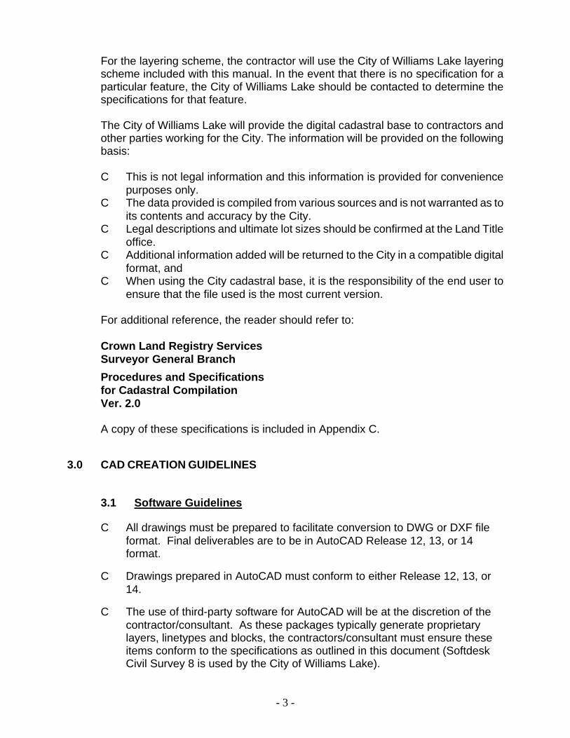
For the layering scheme, the contractor will use the City of Williams Lake layering scheme included with this manual. In the event that there is no specification for a particular feature, the City of Williams Lake should be contacted to determine the specifications for that feature. The City of Williams Lake will provide the digital cadastral base to contractors and other parties working for the City. The information will be provided on the following basis: C This is not legal information and this information is provided for convenience
purposes only. C The data provided is compiled from various sources and is not warranted as to
its contents and accuracy by the City. C Legal descriptions and ultimate lot sizes should be confirmed at the Land Title
office. C Additional information added will be returned to the City in a compatible digital
format, and C When using the City cadastral base, it is the responsibility of the end user to
ensure that the file used is the most current version. For additional reference, the reader should refer to: Crown Land Registry Services Surveyor General Branch Procedures and Specifications for Cadastral Compilation Ver. 2.0 A copy of these specifications is included in Appendix C.
3.0 CAD CREATION GUIDELINES
3.1 Software Guidelines
C All drawings must be prepared to facilitate conversion to DWG or DXF file format. Final deliverables are to be in AutoCAD Release 12, 13, or 14 format.
C Drawings prepared in AutoCAD must conform to either Release 12, 13, or 14.
C The use of third-party software for AutoCAD will be at the discretion of the contractor/consultant. As these packages typically generate proprietary layers, linetypes and blocks, the contractors/consultant must ensure these items conform to the specifications as outlined in this document (Softdesk Civil Survey 8 is used by the City of Williams Lake).
- 4 -
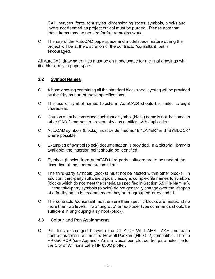
C All linetypes, fonts, font styles, dimensioning styles, symbols, blocks and layers not deemed as project critical must be purged. Please note that these items may be needed for future project work.
C The use of the AutoCAD paperspace and modelspace feature during the project will be at the discretion of the contractor/consultant, but is encouraged.
All AutoCAD drawing entities must be on modelspace for the final drawings with title block only in paperspace.
3.2 Symbol Names C A base drawing containing all the standard blocks and layering will be provided
by the City as part of these specifications.
C The use of symbol names (blocks in AutoCAD) should be limited to eight characters.
C Caution must be exercised such that a symbol (block) name is not the same as other CAD filenames to prevent obvious conflicts with duplication.
C AutoCAD symbols (blocks) must be defined as ABYLAYER@ and ABYBLOCK@ where possible.
C Examples of symbol (block) documentation is provided. If a pictorial library is available, the insertion point should be identified.
C Symbols (blocks) from AutoCAD third-party software are to be used at the
discretion of the contractor/consultant.
C The third-party symbols (blocks) must not be nested within other blocks. In addition, third-party software typically assigns complex file names to symbols (blocks which do not meet the criteria as specified in Section 5.5 File Naming). These third-party symbols (blocks) do not generally change over the lifespan of a facility and it is recommended they be Aungrouped@ or exploded.
C The contractor/consultant must ensure their specific blocks are nested at no more than two levels. Two Aungroup@ or Aexplode@ type commands should be sufficient in ungrouping a symbol (block).
3.3 Colour and Pen Assignments C Plot files exchanged between the CITY OF WILLIAMS LAKE and each
contractor/consultant must be Hewlett Packard (HP-GL2) compatible. The file HP 650.PCP (see Appendix A) is a typical pen plot control parameter file for the City of Williams Lake HP 650C plotter.
- 5 -
3.4 Fonts and Text Sizes C One of the advantages of CAD is the availability of fonts and the flexibility in
managing text sizes. However, given the variety of different conventions, one system must be used.
C Third-party fonts must not be used. These fonts may not be resident of the CITY OF WILLIAMS LAKE and other contractor/consultant workstations. Each time drawings with unique fonts are initially opened on a computer using standard fonts, the user must spend extra time and effort in re-specifying fonts sets.
C The recommended font for all notations will be ASIMPLEX or SOFTDESK MLEROY L @ or of equivalent style. Other fonts are permitted provided that these fonts are resident in AutoCAD.
3.5 Base Drawings C The layer, ABMBASE@, must be used as the staging layer for inserting and
referencing external drawings.
C The XREF drawings will be inserted as symbols (blocks) at the coordinates (0,0) with a scale factor of 1.

- 6 -
City of Williams Lake NAME OF PROJECT JOE CONSULTANTS LTD. LG1A201 - Site Plan LG1A203 - Sections LG1E201 - Key Plan Jan - 1995 1 of 1
3.6 File Storage and Transfer C All files transferred back to the CITY OF WILLIAMS LAKE must be in the
standard AutoCAD DWG format. Any AutoCAD blocks and XREF=s must also be included.
C The recommended media is a 3.5@ 1.44 MB high density DOS formatted diskette. The PKUNZIP or WINZIP software can be used where drawing(s) exceed 1.44 MB in size or a compact disk (CD-R) may be used.
C The information and format on the label for the computer disk must be as follows:
Name of City of Williams Lake Project Name of Contractor or Consultant Name of CAD Files and Discipline Date of Last Drawing Revision Diskette Number of Total Diskettes in Set

DIGITAL DRAWING STANDARDS
SECTION 4 STANDARD LAYERS FOR CAD

CITY OF WILLIAMS LAKE
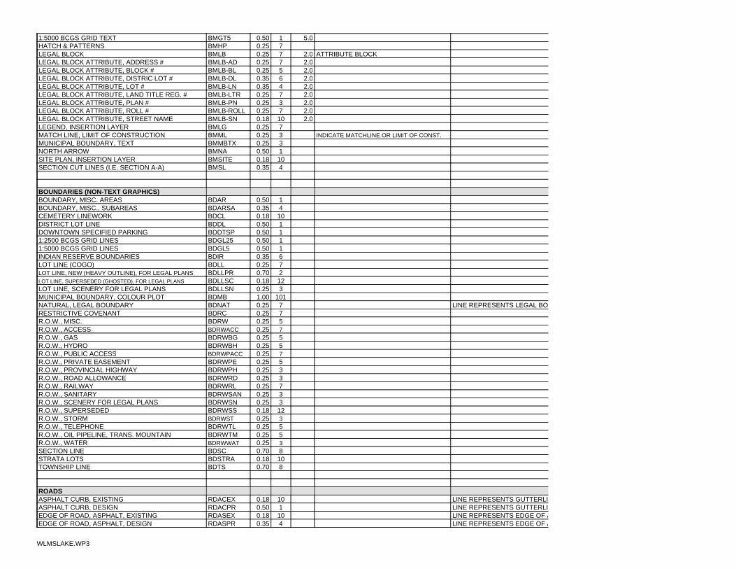
STANDARD LAYERS FOR CAD
SECTION PAGE Standard Pen Weights and Colours 1 Survey 2 Base Map, Boundary Text 2 Boundaries (Non-Text Graphics) 3 Roads 4 Topographic Data 4 Water Utility 6 Storm Sewer 7 Sanitary Sewer 8 Hydro Utility 9 Telephone Utility 9 Gas Utility 9 Oil Pipeline Utility 10 Traffic Markings 10 Traffic Signal Fixtures/Streetlighting 11 Profiles/Details 12 Non-plotted Features 13 Zoning 13 Official Community Plan 13

Standard Layers for CADCoordinate Systems: City of Williams LakeGrid System (CWLGS)Elevation Datum: Geodetic
Where features are symbols, refer to symbol library referenced by symbol # for specific details
Color by Line Weight
BASE COLORPEN #SHADE#DESC.WT
7100%1Red0.57100%2Yellow0.77100%3Green0.257100%4Cyan0.357100%5Blue0.257100%6Magenta0.357100%7White0.257100%8Gray0.77100%9Gray17100%100.18
25090%110.1825175%120.1825260%130.1825345%140.1825430%150.1825515%160.18
All colours above 16 should match pen number to color number.zoning, creeks, lakes and other features.Reserved for plotting shades of colours, typically for
WLMSLAKE1.WP3 Page 1

POSITIONAL VERIFICATIONATTRIBUTES OR DESCRIPTIVE TEXTmmSIZETEXT
COL #mmWT
LINE
CODEFEATURELAYER/
SURVEY1.050.25SVAIRTAIRPHOTO TARGET
INTERSECTION OF AXIS IS PO1.070.25SVAPALUMINUM POST
WLMSLAKE.WP3

1.070.25SVBEATXBEARING, TEXT1.0100.18SVBLBASELINE, TRAVERSE LINES
70.25SVCMDECONTROL MONUMENT, DESTROYED70.25SVCMFNCONTROL MONUMENT, FOUND70.25SVCMPLCONTROL MONUMENT, PLACED
CENTRE OF CIRCLE IS POSITI70.25SVCPFNCONCRETE POST, FOUNDCENTRE OF CIRCLE IS POSITI70.25SVCPPLCONCRETE POST, PLACED
1.070.25SVDITXDISTANCE, TEXT100.18SVDLDISTANCE TIE LINES
2.0100.18SVDODIMENSIONS, OFFSETS70.25SVHPHATCHES AND PATTERNS
CENTRE OF CIRCLE IS POSITI70.25SVIPFNIRON POST, FOUNDCENTRE OF CIRCLE IS POSITI70.25SVIPPLIRON POST, PLACEDCENTRE OF CIRCLE IS POSITI70.25SVKPFNCAPPED POST, FOUNDCENTRE OF CIRCLE IS POSITI1.070.25SVKPPLCAPPED POST, PLACEDMIDPOINT OF SQUARE IS POS70.25SVLPFNLEAD PLUG, FOUNDMIDPOINT OF SQUARE IS POS70.25SVLPPLLEAD PLUG, PLACED
100.18SVRLRADIAL TIE LINES OF ARCSCENTRE OF CIRCLE IS POSITI70.25SVRPFNROCK POST, FOUNDCENTRE OF CIRCLE IS POSITI70.25SVRPPLROCK POST, PLACEDCENTRE OF CROSS IS POSITIO70.25SVSEEXSPOT ELEVATION, EXISTINGCENTRE OF CROSS IS POSITIO70.25SVSEPRSPOT ELEVATION, DESIGNCENTRE OF TRIANGLE IS POS70.25SVTHFNTRAVERSE HUB, FOUNDCENTRE OF TRIANGLE IS POS70.25SVTHPLTRAVERSE HUB, PLACED
2.070.25SVTXTEXT, GENERAL NOTES AND SCHEDULE100.18SVUTNORTHING, EASTING, TICK
2.0100.18SVUTTXNORTHING, EASTING, TEXTCENTRE OF SQUARE IS POSITELEVATION70.25SWCFNVERTICAL CONTROL, FOUNDCENTRE OF SQUARE IS POSITELEVATION70.25SWCPLVERTICAL CONTROL, PLACED
BASE MAP, BOUNDARY TEXT
border and title block drawing standardssee TYPICAL AS CONSTRUCTED DRAWINGS for
3.060.35BMAN-BLBASE MAP ANNOTATION, BLOCK #3.0100.18BMAN-BLSBASE MAP ANNOTATION, BLOCK # SUPERSEDED5.010.50BMAN-DLBASE MAP ANNOTATION, DISTRICT LOT #4.060.35BMAN-LANBASE MAP ANNOTATION, LANE2.0100.18BMAN-LNSBASE MAP ANNOTATION, LOT # SUPERSEDED2.070.25BMAN-LTRBASE MAP ANNOTATION, LAND TITLE REG. #2.030.25BMAN-PNBASE MAP ANNOTATION, PLAN #2.0100.18BMAN-PNSBASE MAP ANNOTATION, PLAN # SUPERSEDED2.050.25BMAN-RWBASE MAP ANNOTATION, RIGHT OF WAY PLAN #5.010.50BMAN-SCBASE MAP ANNOTATION, SECTION #5.010.50BMAN-SNBASE MAP ANNOTATION, STREET NAME5.010.50BMAN-TSBASE MAP ANNOTATION, TOWNSHIP #
70.25BMBASEXREF STAGING LAYER2.070.25BMBDDODIMENSIONS & OFFSETS1.570.25BMBDLLLOT LINE LENGTH NOTATIONS2.070.25BMBDTXTEXT, BOUNDARIES, GENERAL NOTES
L100100.18BMBT18BORDER & TITLE BLOCK, L100L12070.25BMBT25BORDER & TITLE BLOCK, L120L14040.35BMBT35BORDER & TITLE BLOCK, L140L17510.50BMBT50BORDER & TITLE BLOCK, L175L24080.70BMBT70BORDER & TITLE BLOCK, L240
100.18BMBTGDBORDER & TITLE BLOCK, GRID LINES70.25BMBTLBORDER & TITLE BLOCK, LINEWORK70.25BMBTLOBORDER & TITLE BLOCK, LOGO91.00BMBTWBORDER & TITLE BLOCK, WIDELINE
2.560.35BMCMCEMETERY MARKERS5.010.50BMGT251:2500 BCGS GRID TEXT
WLMSLAKE.WP3
5.010.50BMGT51:5000 BCGS GRID TEXT70.25BMHPHATCH & PATTERNS
ATTRIBUTE BLOCK2.070.25BMLBLEGAL BLOCK2.070.25BMLB-ADLEGAL BLOCK ATTRIBUTE, ADDRESS #2.050.25BMLB-BLLEGAL BLOCK ATTRIBUTE, BLOCK #2.060.35BMLB-DLLEGAL BLOCK ATTRIBUTE, DISTRIC LOT #2.040.35BMLB-LNLEGAL BLOCK ATTRIBUTE, LOT #2.070.25BMLB-LTRLEGAL BLOCK ATTRIBUTE, LAND TITLE REG. #2.030.25BMLB-PNLEGAL BLOCK ATTRIBUTE, PLAN #2.070.25BMLB-ROLLLEGAL BLOCK ATTRIBUTE, ROLL #2.0100.18BMLB-SNLEGAL BLOCK ATTRIBUTE, STREET NAME
70.25BMLGLEGEND, INSERTION LAYERINDICATE MATCHLINE OR LIMIT OF CONST.30.25BMMLMATCH LINE, LIMIT OF CONSTRUCTION
30.25BMMBTXMUNICIPAL BOUNDARY, TEXT10.50BMNANORTH ARROW100.18BMSITESITE PLAN, INSERTION LAYER40.35BMSLSECTION CUT LINES (I.E. SECTION A-A)
BOUNDARIES (NON-TEXT GRAPHICS)10.50BDARBOUNDARY, MISC. AREAS40.35BDARSABOUNDARY, MISC., SUBAREAS100.18BDCLCEMETERY LINEWORK10.50BDDLDISTRICT LOT LINE10.50BDDTSPDOWNTOWN SPECIFIED PARKING 10.50BDGL251:2500 BCGS GRID LINES10.50BDGL51:5000 BCGS GRID LINES60.35BDIRINDIAN RESERVE BOUNDARIES70.25BDLLLOT LINE (COGO)20.70BDLLPRLOT LINE, NEW (HEAVY OUTLINE), FOR LEGAL PLANS120.18BDLLSCLOT LINE, SUPERSEDED (GHOSTED), FOR LEGAL PLANS30.25BDLLSNLOT LINE, SCENERY FOR LEGAL PLANS
1011.00BDMBMUNICIPAL BOUNDARY, COLOUR PLOTLINE REPRESENTS LEGAL BO70.25BDNATNATURAL, LEGAL BOUNDARY
70.25BDRCRESTRICTIVE COVENANT50.25BDRWR.O.W., MISC.70.25BDRWACCR.O.W., ACCESS50.25BDRWBGR.O.W., GAS50.25BDRWBHR.O.W., HYDRO70.25BDRWPACCR.O.W., PUBLIC ACCESS50.25BDRWPER.O.W., PRIVATE EASEMENT30.25BDRWPHR.O.W., PROVINCIAL HIGHWAY30.25BDRWRDR.O.W., ROAD ALLOWANCE70.25BDRWRLR.O.W., RAILWAY30.25BDRWSANR.O.W., SANITARY30.25BDRWSNR.O.W., SCENERY FOR LEGAL PLANS120.18BDRWSSR.O.W., SUPERSEDED30.25BDRWSTR.O.W., STORM50.25BDRWTLR.O.W., TELEPHONE50.25BDRWTMR.O.W., OIL PIPELINE, TRANS. MOUNTAIN30.25BDRWWATR.O.W., WATER80.70BDSCSECTION LINE100.18BDSTRASTRATA LOTS80.70BDTSTOWNSHIP LINE
ROADSLINE REPRESENTS GUTTERLI100.18RDACEXASPHALT CURB, EXISTINGLINE REPRESENTS GUTTERLI10.50RDACPRASPHALT CURB, DESIGNLINE REPRESENTS EDGE OF A100.18RDASEXEDGE OF ROAD, ASPHALT, EXISTINGLINE REPRESENTS EDGE OF A40.35RDASPREDGE OF ROAD, ASPHALT, DESIGN
WLMSLAKE.WP3

LINE REPRESENTS OUTLINE OHEIGHT100.18RDBREXBARRIER, EXISTINGLINE REPRESENTS OUTLINE OHEIGHT40.35RDBRPRBARRIER, DESIGNLINE REPRESENTS GUTTERLI100.18RDCGEXCONC. CURB AND GUTTER, EXISTINGLINE REPRESENTS GUTTERLI10.50RDCGPRCON. CURB AND GUTTER, DESIGNLINE REPRESENTS CENTRELI100.18RDCLCENTERLINES
2.0100.18RDDOEXDIMENSIONS, OFFSETS, EXISTING FEATURES2.070.25RDDOPRDIMENSIONS, OFFSETS, DESIGN FEATURES
110.18RDDTEXEDGE OF DIRT ROAD, EXISTING30.25RDDWCEXDRIVEWAYS, EXISTING CONCRETE100.18RDDWGEXDRIVEWAYS, EXISITNG GRAVEL
LINE REPRESENTS EDGE OF D50.25RDDWPEXDRIVEWAYS, EXISTING ASPHALT PAVEMENTLINE REPRESENTS EDGE OF D60.35RDDWPRDRIVEWAYS, DESIGNLINE REPRESENTS EDGE OF G100.18RDGVEXEDGE OF ROAD, GRAVEL, EXISTINGLINE REPRESENTS EDGE OF G60.35RDGVPREDGE OF ROAD, GRAVEL, DESIGNLINE REPRESENTS OUTLINE OMATERIAL, I.E., CONCRETE, ASPHALT100.18RDPCEXPARKING, CURBS, EXISTINGLINE REPRESENTS OUTLINE OMATERIAL, I.E., CONCRETE, ASPHALT60.35RDPCPRPARKING, CURBS, DESIGNLINE REPRESENTS EDGE OF S100.18RDSHEXSHOULDER, EXISTINGLINE REPRESENTS EDGE OF S70.25RDSHPRSHOULDER, DESIGNOUTLINE TO SCALE100.18RDSLEXSIDEWALK, LETDOWN, EXISTINGOUTLINE TO SCALE60.35RDSLPRSIDEWALK, LETDOWN, DESIGNLINE REPRESENTS EDGES OF100.18RDSWEXSIDEWALK, EXISTINGLINE REPRESENTS EDGES OF40.35RDSWPRSIDEWALK, DESIGNCENTRE OF FIGURE REPRESENT50.25RDTHTESTHOLES
2.070.25RDTXTEXT, GENERAL, NOTES AND SCHEDULE2.0100.18RDTXEXTEXT, EXISTING FEATURES2.040.35RDTXPRTEXT, DESIGN FEATURES
TOPOGRAPHIC DATAOUTLINE TO SCALE100.18TPBKEXBACKSTOP, EXISTINGOUTLINE TO SCALE80.70TPBKPRBACKSTOP, DESIGN
110.18TPBLEXBRUSH LINE, <3m HEIGHT, EXISITNGOUTLINE REPRESENTS EDGE 100.18TPBNEXBENCH, PARK OR BUS ETC. EXISTINGOUTLINE REPRESENTS EDGE 40.35TPBNPRBENCH, PARK OR BUS ETC. DESIGNOUTLINE REPRESENTS BUILDELEVATIONS @ CORNERS, BUILDING USE100.18TPBOEXBUILDING OUTLINE, EXISTINGOUTLINE REPRESENTS BUILDELEVATIONS @ CORNERS, BUILDING USE80.70TPBOPRBUILDING OUTLINE, DESIGN
ELEVATIONS @ CORNERS100.18TPBREXBRIDGE DECK, EXISTINGELEVATIONS @ CORNERS40.35TPBRPRBRIDGE DECK, DESIGN
OUTLINE TO SCALEELEVATIONS @ CORNERS100.18TPBSEXBUS SHELTER, EXISTINGOUTLINE TO SCALEELEVATIONS @ CORNERS60.35TPBSPRBUS SHELTER, DESIGN
110.18TPBUEXBUSH, EXISTINGLINE REPRESENTS OUTLINE OELEVATIONS @ CORNERS100.18TPCPEXCONCRETE PAD, EXISTINGLINE REPRESENTS OUTLINE OELEVATIONS @ CORNERS60.35TPCPPRCONCRETE PAD, DESIGNLINE REPRESENTS NATURAL 50.25TPCRCREEK, CENTRELINE
50.25TPCRBTCREEK, BOTTOM OF BANK1310.25TPCRSHCREEK SHADING (BLUE)
50.25TPCRTPCREEK, TOP OF BANKZ COORDINATE EQUALS ELEV130.18TPCTCONTOURCONTOUR IN AREA OF OBSCU130.18TPCTDCONTOUR, INDETERMINATELINE REPRESENTS 100 YEAR 40.35TPCTHWCONTOUR, 100 YEAR FLOODZ COORDINATE EQUALS ELEV100.18TPCTINCONTOUR, INDEXINDEX CONTOUR IN AREA OF 100.18TPCTINDCONTOUR, INDEX, INDETERMINATE
2.530.25TPCTTXCONTOUR, LABEL2.050.25TPDODIMENSIONS, OFFSETS
LINE REPRESENTS CENTRELIGROUND ELEV. @ NODES, TYPE, HEIGHT100.18TPFEEXFENCE, EXISTINGLINE REPRESENTS CENTRELIGROUND ELEV. @ NODES, TYPE, HEIGHT40.35TPFEPRFENCE, DESIGNOUTLINE TO SCALE100.18TPFNEXFOUNTAIN, EXISTINGOUTLINE TO SCALE80.70TPFNPRFOUNTAIN, DESIGNARROWS REPRESENT DIRECT100.18TPGREXGRADING, FLOW ARROWS, EXISTING
WLMSLAKE.WP3

ARROWS REPRESENT DIRECT60.35TPGRPRGRADING, FLOW ARROWS, DESIGNLINE REPRESENTS CENTRELIELEVATIONS @ ENDS100.18TPGTEXGATE, EXISTINGLINE REPRESENTS CENTRELIELEVATIONS @ ENDS40.35TPGTPRGATE, DESIGNLINE REPRESENTS OUTLINE O110.18TPHEDEXHEDGE, EXISTING
30.25TPHPHATCHES AND PATTERNSLINE REPRESENTS NATURAL 50.25TPLKLAKE
1310.25TPLKSHLAKE SHADING (BLUE)IDENTIFY TOPO FEATURE, ELEV. (IF APP.)100.18TPOFEXOTHER TOPOGRAPHICAL FEATURES, EXISTINGIDENTIFY TOPO FEATURE, ELEV. (IF APP.)40.35TPOFPROTHER TOPOGRAPHICAL FEATURES, DESIGN
OUTLINE TO SCALE100.18TPPBEXPLANTER BOX, EXISTINGOUTLINE TO SCALE40.35TPPBPRPLANTER BOX, DESIGNOUTLINE TO SCALE100.18TPPLEXPOOL, OUTDOOR, EXISTINGOUTLINE TO SCALE60.35TPPLPRPOOL, OUTDOOR, DESIGN
ELEVATIONS @ BASE100.18TPPMEXPARKING METER/PAY STATION, EXISTINGELEVATIONS @ BASE40.35TPPMPRPARKING METER/PAY STATION, DESIGNELEVATIONS @ BASE100.18TPRBEXRAILWAY BARRICADE, EXISTINGELEVATIONS @ BASE60.35TPRBPRRAILWAY BARRICADE, DESIGN
LINE REPRESENTS NATURAL 1310.25TPRIRIVER, SHADING (BLUE)50.25TPRITOERIVER TOE OF BANK50.25TPRITOPRIVER TOP OF BANK
OUTLINE OF TRACK TO SCALE100.18TPRLEXRAILWAY, EXISTING100.18TPRLMISCRAILWAY OBJECTS MISC.
OUTLINE TO SCALE100.18TPRNEXRINK, OUTDOOR, EXISTINGOUTLINE TO SCALE20.70TPRNPRRINK, OUTDOOR, DESIGN
ELEVATIONS @ BASE100.18TPRSEXRAILWAY SIGNAL, EXISTINGELEVATIONS @ BASE60.35TPRSPRRAILWAY SIGNAL, DESIGN
OUTLINE TO SCALEELEVATIONS @ CORNERS100.18TPSFEXSPORTS FIELD, EXISTINGOUTLINE TO SCALEELEVATIONS @ CORNERS80.70TPSFPRSPORTS FIELD, DESIGNOUTLINE OF BASE100.18TPSPEXSTOCKPILE, LARGE GRAVEL, EXISTINGREPRESENTED TO SCALEELEVATIONS @ CORNERS100.18TPSTEXSTAIRWAY, EXISTINGREPRESENTED TO SCALEELEVATIONS @ CORNERS 40.35TPSTPRSTAIRWAY, DESIGNLINE REPRESENTS OUTLINE O100.18TPTAEXLANDSCAPED AREA, EXISTINGLINE REPRESENTS OUTLINE O20.70TPTAPRLANDSCAPED AREA, DESIGN
REPRESENTS DRIP LINECENTRE REPRESENTS CENTRE
GROUND, SPECIES (CONIFER./DECID.)DIAMETER MEASURED @ 1.0M ABOVE
100.18TPTEEXTREE, EXISTING
REPRESENTS DRIP LINECENTRE OF CIRCLE REPRESENT
GROUND, SPECIES (CONIFER./DECID.)DIAMETER MEASURED @ 1.0M ABOVE
30.25TPTEPRTREE, DESIGNLINE REPRESENTS OUTLINE O100.18TPTLEXTREELINE, EXISTING LINE REPRESENTS OUTLINE O30.25TPTLPRTREELINE, DESIGNOUTLINE TO SCALETYPE, ELEVATIONS @ CORNERS100.18TPTNEXTANK, EXISTINGOUTLINE TO SCALETYPE, ELEVATIONS @ CORNERS60.35TPTNPRTANK, DESIGNOUTLINE REPRESENTS BOTTO100.18TPTOETOE OF SLOPE, BOTTOMOUTLINE REPRESENTS TOP O100.18TPTOPTOP OF SLOP, TOPOUTLINE REPRESENTS TRAIL TYPE, GROUND ELEVATIONS AT NODES100.18TPTREXTRAIL, EXISTINGOUTLINE REPRESENTS TRAIL TYPE, GROUND ELEVATIONS AT NODES60.35TPTRPRTRAIL, DESIGNOUTLINE TO SCALEELEVATIONS @ BASE100.18TPTWEXTOWER, EXISTINGOUTLINE TO SCALEELEVATIONS @ BASE40.35TPTWPRTOWER, DESIGN
2.070.25TPTXTEXT, GENERAL, NOTES AND SCHEDULE2.070.25TPTXEXTEXT, EXISTING FEATURES2.030.25TPTXPRTEXT, DESIGN FEATURES
LINE REPRESENTS OUTLINE OELEVATIONS @ CORNERS, TYPE, HEIGHT100.18TPWLEXWALL, EXISTINGLINE REPRESENTS OUTLINE OELEVATIONS @ CORNERS, TYPE, HEIGHT60.35TPWLPRWALL, DESIGN
WATER UTILITY100.18WTATEXANODE TEST STATION, EXISTING60.35WTATPRANODE TEST STATION, DESIGN
CENTRE OF CIRCLE IS CENTRELEV:TOP100.18WTAVEXAIRVALVE, EXISTINGCENTRE OF CIRCLE IS CENTRELEV:TOP40.35WTAVPRAIRVALVE, DESIGNMIDPOINT OF SYMBOL IS CENELEV:TOP100.18WTBFEXBLOWOFF, EXISTING
WLMSLAKE.WP3

MIDPOINT OF SYMBOL IS CENELEV:TOP60.35WTBFPRBLOWOFF, DESIGNOUTLINE TO SCALE100.18WTBSEXBOOSTER STATION, EXISTINGOUTLINE TO SCALE40.35WTBSPRBOOSTER STATION, DESIGNMIDPOINT OF LONG LINE IS CEINVERT100.18WTCEEXCAPPED END, EXISTINGMIDPOINT OF LONG LINE IS CEINVERT40.35WTCEPRCAPPED END, DESIGN
100.18WTCPEXCATHODIC PROTECTION, EXISTING40.35WTCPPRCATHODIC PROTECTION, DESIGN
2.0100.18WTDOEXDIMENSIONS, OFFSETS, EXISTING FEATURES2.070.25WTDOPRDIMENSIONS, OFFSETS, DESIGN FEATURES
100.18WTFDEXFIRE DEPT. CONNECTION, EXISTING40.35WTFDPRFIRE DEPT. CONNECTION, DESIGN
CENTRE OF CIRCLE IS CENTRELEV:TOP100.35WTFOEXFLUSHOUT VALVE, EXISTINGCENTRE OF CIRCLE IS CENTRELEV:TOP60.18WTFOPRFLUSHOUT VALVE, DESIGNCENTRE OF CIRCLE IS CENTRELEV:GROUND HEIGHT100.18WTHYEXHYDRANT, EXISTINGCENTRE OF CIRCLE IS CENTRELEV:GROUND HEIGHT40.35WTHYPRHYDRANT, DESIGNOUTLINE TO SCALE100.18WTMCEXMETER, CHAMBER, EXISTINGOUTLINE TO SCALE40.35WTMCPRMETER, CHAMBER, DESIGNMIDPOINT OF SYMBOL IS CEN100.18WTMEEXMETER, EXISTINGMIDPOINT OF SYMBOL IS CEN60.35WTMEPRMETER, DESIGN
IDENTIFY FIXTURE, ELEV. (IF APPLICABLE)100.18WTOTEXOTHER UTILITY FIXTURES, EXISTINGIDENTIFY FIXTURE, ELEV. (IF APPLICABLE)40.35WTOTPROTHER UTILITY FIXTURES, DESIGN
LINE REPRESENTS CENTRELI"ABANDONED"END, BENDS, TEXT ATTRIBUTETYPE, DIAMETER, INVERTS: BEGINNING,
100.18WTPIABPIPE, ABANDONED
LINE REPRESENTS CENTRELIEND, BENDSTYPE DIAMETER, INVERTS: BEGINNING,
100.18WTPIEXPIPE, EXISTING
LINE REPRESENTS CENTRELIEND, BENDSTYPE, DIAMETER INVERTS: BEGINNING,
20.70WTPIPRPIPE, DESIGNOUTLINE REPRESENTS CORN100.18WTPPEXPUMP, EXISTINGOUTLINE REPRESENTS CORN60.35WTPPPRPUMP, DESIGN
ELEV:TOP100.18WTPSEXPRESSURE REDUCING VALVE, EXISTINGELEV:TOP40.35WTPSPRPRESSURE REDUCING VALVE, DESIGN
OUTLINE REPRESENTS CORN100.18WTRVEXRESERVOIR, EXISTINGOUTLINE REPRESENTS CORN60.35WTRVPRRESERVOIR, DESIGNCENTRE OF CIRCLE IS CENTRELEV:GROUND HT.100.18WTSPEXSTANDPIPE, EXISTINGCENTRE OF CIRCLE IS CENTRELEV:GROUND HT.40.35WTSPPRSTANDPIPE, DESIGNCENTRE OF CIRCLE IS CENTRINVERTS: @ MAIN, @ PROPERTY LINE100.18WTSVEXSERVICE, EXISTINGCENTRE OF CIRCLE IS CENTRINVERTS: @ MAIN, @ PROPERTY LINE40.35WTSVPRSERVICE, DESIGN
2.070.25WTTXTEXT, GENERAL, NOTES AND SCHEDULE2.0100.18WTTXEXTEXT, EXISTING FEATURES2.040.35WTTXPRTEXT, DESIGN FEATURES
MIDPOINT OF SYMBOL IS CENPRIVATE GVRD IF APPLICABLEELEV:TOP INDICATE ABANDONED,
100.18WTVAEXVALVE, EXISTING
MIDPOINT OF SYMBOL IS CENPRIVATE GVRD IF APPLICABLEELEV:TOP, INDICATE ABANDONED,
40.35WTVAPRVALVE, DESIGNOUTLINE REPRESENTS CORN100.18WTVCEXVALVE, CHAMBER, EXISTINGOUTLINE REPRESENTS CORN40.35WTVCPRVALVE, CHAMBER, DESIGN
ELEV:TOP100.18WTWLEXWELL, EXISTINGELEV:TOP60.35WTWLPRWELL, DESIGN
STORM SEWER100.18STBWEXVALVE, BACKWATER, EXISTING60.35STBWPRVALVE, BACKWATER, DESIGN
MIDPOINT OF SYMBOL IS CENABANDONED, PRIVATE, IF APPLICABLEELEV:TOP, INVERT:INDICATE
100.18STCBEXCATCH BASIN, EXISTING
MIDPOINT OF SYMBOL IS CENABANDONED, PRIVATE, IF APPLICABLEELEV:TOP, INVERTS:INDICATE
40.35STCBPRCATCH BASIN, DESIGNMIDPOINT OF LONG LINE IS CEINVERT100.18STCEEXCAPPED END, EXISTING
WLMSLAKE.WP3

MIDPOINT OF LONG LINE IS CEINVERT40.35STCEPRCAPPED END, DESIGNCENTRE OF CIRCLE REPRESENTS CETOP ELEV.100.18STCOEXCLEANOUT, EXISTINGCENTRE OF CIRCLE REPRESENTS CETOP ELEV.60.35STCOPRCLEANOUT, DESIGNENDPOINT OF LINES REPRESENTS POINVERT100.18STCVEXDETENTION CHAMBER, EXISTINGENDPOINT OF LINES REPRESENTS POINVERT60.35STCVPRDETENTION CHAMBER, DESIGN
ARROW POINT REPRESENTS 100.18STDIEXDITCH, EXISTING
ARROW POINT REPRESENTS 40.35STDIPRDITCH, DESIGN2.0100.18STDOEXDIMENSIONS, OFFSETS, EXISTING FEATURES2.070.25STDOPRDIMENSIONS, OFFSETS, DESIGN FEATURES
ARROW REPRESENTS CENTR60.35STFPFLOOD PATH
CHAMBERCENTRE OF CIRCLE REPRESENT
TOP ELEV.100.18STICEXINSPECTION CHAMBER, EXISTING
CHAMBERCENTRE OF CIRCLE REPRESENT
TOP ELEV.40.35STICPRINSPECTION CHAMBER, DESIGNOUTLINE TO SCALEINVERT100.18STISEXINLET STRUCTURE, EXISTINGOUTLINE TO SCALEINVERT40.35STISPRINLET STRUCTURE, DESIGNCENTRE OF CIRCLE IS CENTRELEVATIONS:TOP, INVERT100.18STLDEXLAWN DRAIN, EXISTINGCENTRE OF CIRCLE IS CENTRELEVATIONS:TOP, INVERT60.35STLDPRLAWN DRAIN, DESIGNCENTRE OF CIRCLE REPRESEELEVATIONS:RIM, INVERT @ CENTRELINE100.18STMHEXMANHOLE, EXISTINGCENTRE OF CIRCLE REPRESEELEVATIONS:RIM, INVERT @ CENTRELINE40.35STMHPRMANHOLE, DESIGN
IDENTIFY FIXTURE, ELEV. (IF APPLICABLE)100.18STOFEXOTHER FIXTURES, EXISTINGIDENTIFY FIXTURE, ELEV. (IF APPLICABLE)40.35STOFPROTHER FIXTURES, DESIGN
OUTLINE TO SCALE100.18STOSEXOUTFALL STRUCTURE, EXISTINGOUTLINE TO SCALE60.35STOSPROUTFALL STRUCTURE, DESIGN
LINE REPRESENTS CENTRELIEND, BENDSTYPE, DIAMETER, INVERTS:BEGINNING,
100.18STPIEXPIPE, EXISTING
LINE REPRESENTS CENTRELIEND, BENDSTYPE, DIAMETER, INVERTS:BEGINNING,
20.70STPIPRPIPE, DESIGNOUTLINE OF PUMP STATION T100.18STPPEXPUMP, EXISTINGOUTLINE OF PUMP STATION T40.35STPPPRPUMP, DESIGNOUTLINE TO SCALE100.18STRREXRIP RAP, EXISTINGOUTLINE TO SCALE60.35STRRPRRIP RAP, DESIGNOUTER LINE IS UPPER TOE, IN100.18STSBEXSEDIMENTATION BASIN, EXISTINGOUTER LINE IS UPPER TOE, IN40.35STSBPRSEDIMENTATION BASIN, DESIGNOUTLINE TO SCALE100.18STSUEXSUMP, EXISTINGOUTLINE TO SCALE60.35STSUPRSUMP, DESIGNLINE REPRESENTS CENTRELIINVERTS:@MAIN,@PROPERTY LINE100.18STSVEXSERVICE, EXISTINGLINE REPRESENTS CENTRELIINVERTS:@MAIN,@PROPERTY LINE40.35STSVPRSERVICE, DESIGN
2.070.25STTXTEXT, GENERAL, NOTES AND SCHEDULE2.0100.18STTXEXTEXT, EXISTING FEATURES2.040.35STTXPRTEXT, DESIGN FEATURES
100.18STVAEXVALVE, GATE, EXISTING40.35STVAPRVALVE, GATE, DESIGN
OUTLINE TO SCALE100.18STWCWATER COURSE, STORM WATER
SANITARY SEWERMIDPOINT OF LONG LINE IS CEINVERT100.18SNCEEXCAPPED END, EXISTINGMIDPOINT OF LONG LINE IS CEINVERT60.35SNCEPRCAPPED END, DESIGNCENTRE OF CIRCLE REPRESENTELEVATION:TOP100.18SNCOEXCLEANOUT, EXISTINGCENTRE OF CIRCLE REPRESENTELEVATION:TOP40.35SNCOPRCLEANOUT, DESIGN
2.0100.18SNDOEXDIMENSIONS, OFFSETS, EXISTING FEATURES2.070.25SNDOPRDIMENSIONS, OFFSETS, DESIGN FEATURES
LINE REPRESENTS CENTRELIEND, BENDSTYPE, DIAMETER, INVERTS:BEGINNING,
100.18SNFMEXFORCEMAIN, EXISTING
LINE REPRESENTS CENTRELIEND, BENDSTYPE, DIAMETER, INVERTS:BEGINNING,
20.70SNFMPRFORCEMAIN, DESIGNOUTLINE TO SCALEELEVATION:TOP100.18SNGSEXGRINDER STATION, EXISTING
WLMSLAKE.WP3

OUTLINE TO SCALEELEVATION:TOP40.35SNGSPRGRINDER STATION, DESIGNOUTLINE OF TANK TO SCALEELEVATION:TOP100.18SNHTEXHOLDING TANK, EXISTINGOUTLINE OF TANK TO SCALEELEVATION:TOP60.35SNHTPRHOLDING TANK, DESIGN
CHAMBERCENTRE OF CIRCLE REPRESENT
ELEVATION:TOP100.18SNICEXINSPECTION CHAMBER, EXISTING
CHAMBERCENTRE OF CIRCLE REPRESENT
ELEVATION:TOP40.35SNICPRINSPECTION CHAMBER, DESIGNCENTRE OF CIRCLE REPRESEELEVATIONS:RIM, INVERT@ CENTRELINE100.18SNMHEXMANHOLE, EXISTINGCENTRE OF CIRCLE REPRESEELEVATIONS:RIM, [email protected], DESIGN
IDENTIFY FIXTURE, ELEV. (IF APPLICABLE)100.18SNOFEXOTHER FIXTURES, EXISTINGIDENTIFY FIXTURE, ELEV. (IF APPLICABLE)60.35SNOFPROTHER FIXTURES, DESIGN
LINE REPRESENTS CENTRELIBENDSTYPE, DIAMETER, INVERTS:BEGINNING, END,
100.18SNPIEXPIPE, EXISTING
LINE REPRESENTS CENTRELIEND, BENDSTYPE, DIAMETER, INVERTS:BEGINNING,
20.70SNPIPRPIPE, DESIGNOUTLINE OF STATION TO SCAELEVATIONS:RIM, [email protected] STATION, EXISTINGOUTLINE OF STATION TO SCAELEVATIONS:RIM, [email protected] STATION, DESIGN
70.25SNSLSEWER LAGOONSLINE REPRESENTS CENTRELIINVERTS:@MAIN@PROPERTY LINE2.0100.18SNSVEXSERVICE CONNECTION, EXISTINGLINE REPRESENTS CENTRELIINVERTS:@MAIN@PROPERTY LINE40.35SNSVPRSERVICE CONNECTION, DESIGN
70.25SNTXTEXT, GENERAL, NOTES AND SCHEDULE2.0100.18SNTXEXTEXT, EXISTING FEATURES2.040.35SNTXPRTEXT, DESIGN FEATURES
ELEV:TOP100.18SNVAEXGATE VALVE, EXISTINGELEV:TOP60.35SNVAPRGATE VALVE, DESIGN
HYDRO UTILITY110.18HYDOEXDIMENSIONS, OFFSETS, EXISTING FEATURES
WLMSLAKE.WP3

70.25HYDOPRDIMENSIONS, OFFSETS, DESIGN FEATURESGROUND ELEVATION110.18HYGWEXGUYWIRE, EXISTINGGROUND ELEVATION40.35HYGWPRGUYWIRE, DESIGN
MIDPOINT OF SYMBOL REPRE110.18HYJBEXJUNCTION BOX, EXISTINGMIDPOINT OF SYMBOL REPRE60.35HYJBPRJUNCTION BOX, DESIGNOUTLINE REPRESENTS OUTS100.18HYKEXKIOSK, EXISTINGOUTLINE REPRESENTS OUTS60.35HYKPRKIOSK, DESIGNCENTRE OF CIRCLE REPRESENTTOP ELEV.110.18HYMHEXMANHOLE, EXISTINGCENTRE OF CIRCLE REPRESENTTOP ELEV.60.35HYMHPRMANHOLE, DESIGN
IDENTIFY FIXTURE, ELEV. (IF APPLICABLE)110.18HYOFEXOTHER HYDRO FIXTURES, EXISTINGIDENTIFY FIXTURE, ELEV. (IF APPLICABLE)40.35HYOFPROTHER HYDRO FIXTURES, DESIGN
LINE REPRESENTS GROUND PRO110.18HYOHEXOVERHEADLINES, EXISTINGLINE REPRESENTS GROUND PRO70.25HYOHPROVERHEADLINES, DESIGN
110.18HYPOEXTEXT, EXISTING FEATURESCENTRE OF LARGE CIRCLE IS110.18HYPOLEXPOLES, W/LIGHT, EXISTINGCENTRE OF LARGE CIRCLE IS60.35HYPOLPRPOLES, W/LIGHT, DESIGN
40.35HYPOPRTEXT, DESIGN FEATURESOUTLINE REPRESENTS OUTS110.18HYTTEXTRANSMISSION TOWER, EXISTINGOUTLINE REPRESENTS OUTS40.35HYTTPRTRANSMISSION TOWER, DESIGN
70.25HYTXTEXT, GENERAL, NOTES AND SCHEDULECENTRE OF CIRCLE REPRESEGROUND ELEVATION110.18HYTXEXUTILITY POLE, EXISTINGCENTRE OF CIRCLE REPRESEGROUND ELEVATION40.35HYTXPRUTILITY POLE, DESIGNLINE REPRESENTS CENTRELIELEVATIONS:BEGINNING, END, BENDS110.35HYUGEXU/G ELECTRICAL LINES, EXISTINGLINE REPRESENTS CENTRELIELEVATIONS:BEGINNING, END, BENDS80.70HYUGPRU/G ELECTRICAL LINES, DESIGN
TELEPHONE UTILITYLINE REPRESENTS CENTRELIELEVATIONS: BEGINNING, ENDS, BENDS110.18TECDEXCONDUIT, EXISTINGLINE REPRESENTS CENTRELIELEVATIONS: BEGINNING, ENDS, BENDS80.70TECDPRCONDUIT, DESIGN
2.0110.18TEDOEXDIMENSIONS, OFFSETS, EXISTING FEATURE2.070.25TEDOPRDIMENSIONS, OFFSETS, DESIGN FEATURES
CENTRE OF CIRCLE REPRESEELEVATION:TOP110.18TEMHEXMANHOLE, EXISTINGCENTRE OF CIRCLE REPRESEELEVATION:TOP40.35TEMHPRMANHOLE, DESIGN
IDENTIFY FIXTURE, ELEV. (IF APPLICABLE)110.18TEOFEXOTHER TELEPHONE FIXTURES, EXISTINGIDENTIFY FIXTURE, ELEV. (IF APPLICABLE)40.35TEOFPROTHER TELEPHONE FIXTURES, DESIGN
2.070.25TETXTEXT, GENERAL, NOTES AND SCHEDULE2.0110.18TETXEXTEXT, EXISTING FEATURES2.040.35TETXPRTEXT, DESIGN FEATURES
GAS UTILITYLINE REPRESENTS CENTRELI110.18GMDPMAIN, EXISTING DP PRESSLINE REPRESENTS CENTRELI10.50GMDPPRMAIN, DESIGN DP PRESSLINE REPRESENTS CENTRELI100.18GMIPMAIN, EXISTING IP PRESS
70.25GMTPMAIN, EXISTING TP PRESS2.0110.18GUDOEXDIMENSIONS, OFFSETS, EXISTING FEATURES2.070.25GUDOPRDIMENSIONS, OFFSETS, DESIGN FEATURES
ELEVATION:GROUND100.18GUMKLOCATION MARKER
APPLICABLE)IDENTIFY FIXTURE, ELEV. (IF
110.18GUOFEXOTHER GAS FIXTURES, EXISTINGOUTLINE REPRESENTS CORN110.18GUPPEXPUMP STATION, EXISTINGOUTLINE REPRESENTS CORN40.35GUPPPRPUMP STATION, DESIGN
2.070.25GUTXTEXT, GENERAL, NOTES AND SCHEDULE2.0110.18GUTXEXTEXT, EXISTING FEATURES2.040.35GUTXPRTEXT, DESIGN FEATURES
MIDPOINT OF SYMBOL IS CENELEVATION:TOP110.18GUVAEXVALVE, EXISTINGMIDPOINT OF SYMBOL IS CENELEVATION:TOP40.35GUVAPRVALVE, DESIGN
WLMSLAKE.WP3

OIL PIPELINE UTILITY2.0110.18OPDOEXDIMENSIONS, OFFSETS, EXISTING FEATURES2.070.25OPDOPRDIMENSIONS, OFFSETS, DESIGN FEATURES
ELEVATION:GROUND100.18OPMKLOCATION MARKER
APPLICABLE)IDENTIFY FIXTURE, ELEV. (IF
110.18OPOFEXOTHER OIL UTILITY FIXTURES, EXISTING
APPLICABLE)IDENTIFY FIXTURE, ELEV. (IF
60.35OPOFPROTHER OIL UTILITY FIXTURES, DESIGN
LINE REPRESENTS CENTRELIBENDSTYPE, DIAMETER, INVERTS:BEGINNING, END,
110.18OPPIEXMAIN, EXISTING
LINE REPRESENTS CENTRELIBENDSTYPE, DIAMETER, INVERTS:BEGINNING, END,
20.70OPPIPRMAIN, DESIGNOUTLINE REPRESENTS CORN110.18OPPPEXPUMP STATION, EXISTINGOUTLINE REPRESENTS CORN60.35OPPPPRPUMP STATION, DESIGN
2.070.25OPTXTEXT, GENERAL, NOTES AND SCHEDULES2.0110.18OPTXEXTEXT, EXISTING FEATURES2.060.35OPTXPRTEXT, DESIGN FEATURES
MIDPOINT OF SYMBOL IS CENELEVATION:TOP110.18OPVAEXVALVES, EXISTINGMIDPOINT OF SYMBOL IS CENELEVATION:TOP60.35OPVAPRVALVES, DESIGN
TRAFFIC MARKINGS60.35TMAREXTRAFFIC ARROWS, EXISTING120.50TMARPRTRAFFIC ARROWS, DESIGN400.25TMCLEXCENTRELINE, EXISTING400.35TMCLPRCENTRELINE, DESIGN70.25TMCPEXCURB PAINTING, EXISTING40.35TMCPPRCURB PAINTING, DESIGN60.35TMCWEXCROSSWALK AND STOP BARS, EXISTING10.50TMCWPRCROSSWALK AND STOP BARS, DESIGN70.25TMDVEXDIVIDING LINES, EXISTING40.35TMDVPRDIVIDING LINES, DESIGN
1300.25TMHCEXHANDICAP, EXISTING1300.35TMHCPRHANDICAP, DESIGN
60.35TMHPEXHATCHING AND CHEVRONS, EXISTING10.50TMHPPRHATCHING AND CHEVRONS, DESIGN70.25TMLEEXLANE EDGE, EXISTING40.35TMLEPRLANE EDGE, DESIGN30.25TMPKEXPARKING LINES, EXISTING60.35TMPKPRPARKING LINES, DESIGN60.35TMTPEXTHERMO PLASTIC, EXISTING10.50TMTPPRTHERMO PLASTIC, DESIGN
TRAFFIC SIGNAL FIXTURES/STREETLIGHTINGELEVATION, BASE110.18TRCAEXCROSSWALK ARM, EXISTING
WLMSLAKE.WP3
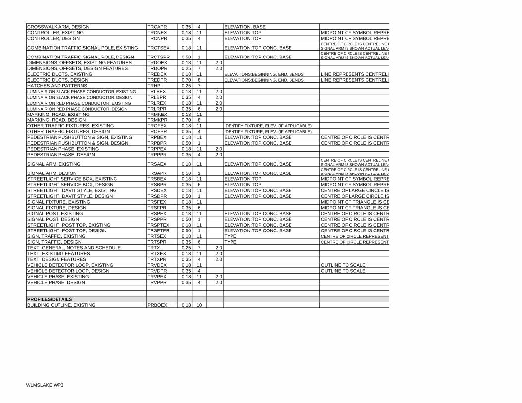
ELEVATION, BASE40.35TRCAPRCROSSWALK ARM, DESIGNMIDPOINT OF SYMBOL REPREELEVATION:TOP110.18TRCNEXCONTROLLER, EXISTINGMIDPOINT OF SYMBOL REPREELEVATION:TOP40.35TRCNPRCONTROLLER, DESIGN
SIGNAL ARM IS SHOWN ACTUAL LENGCENTRE OF CIRCLE IS CENTRELINE O
ELEVATION:TOP CONC. BASE110.18TRCTSEXCOMBINATION TRAFFIC SIGNAL POLE, EXISTING
SIGNAL ARM IS SHOWN ACTUAL LENGCENTRE OF CIRCLE IS CENTRELINE O
ELEVATION:TOP CONC. BASE10.50TRCTSPRCOMBINATION TRAFFIC SIGNAL POLE, DESIGN2.0110.18TRDOEXDIMENSIONS, OFFSETS, EXISTING FEATURES2.070.25TRDOPRDIMENSIONS, OFFSETS, DESIGN FEATURES
LINE REPRESENTS CENTRELIELEVATIONS:BEGINNING, END, BENDS110.18TREDEXELECTRIC DUCTS, EXISTINGLINE REPRESENTS CENTRELIELEVATIONS:BEGINNING, END, BENDS80.70TREDPRELECTRIC DUCTS, DESIGN
70.25TRHPHATCHES AND PATTERNS2.0110.18TRLBEXLUMINAIR ON BLACK PHASE CONDUCTOR, EXISTING2.040.35TRLBPRLUMINAIR ON BLACK PHASE CONDUCTOR, DESIGN2.0110.18TRLREXLUMINAIR ON RED PHASE CONDUCTOR, EXISTING2.060.35TRLRPRLUMINAIR ON RED PHASE CONDUCTOR, DESIGN
110.18TRMKEXMARKING, ROAD, EXISTING80.70TRMKPRMARKING, ROAD, DESIGN
IDENTIFY FIXTURE, ELEV. (IF APPLICABLE)110.18TROFEXOTHER TRAFFIC FIXTURES, EXISTINGIDENTIFY FIXTURE, ELEV. (IF APPLICABLE)40.35TROFPROTHER TRAFFIC FIXTURES, DESIGN
CENTRE OF CIRCLE IS CENTRELEVATION:TOP CONC. BASE110.18TRPBEXPEDESTRIAN PUSHBUTTON & SIGN, EXISTINGCENTRE OF CIRCLE IS CENTRELEVATION:TOP CONC. BASE10.50TRPBPRPEDESTRIAN PUSHBUTTON & SIGN, DESIGN
2.0110.18TRPPEXPEDESTRIAN PHASE, EXISTING2.040.35TRPPPRPEDESTRIAN PHASE, DESIGN
SIGNAL ARM IS SHOWN ACTUAL LENGCENTRE OF CIRCLE IS CENTRELINE O
ELEVATION:TOP CONC. BASE110.18TRSAEXSIGNAL ARM, EXISTING
SIGNAL ARM IS SHOWN ACTUAL LENGCENTRE OF CIRCLE IS CENTRELINE O
ELEVATION:TOP CONC. BASE10.50TRSAPRSIGNAL ARM, DESIGNMIDPOINT OF SYMBOL REPREELEVATION:TOP110.18TRSBEXSTREETLIGHT SERVICE BOX, EXISTINGMIDPOINT OF SYMBOL REPREELEVATION:TOP60.35TRSBPRSTREETLIGHT SERVICE BOX, DESIGNCENTRE OF LARGE CIRCLE ISELEVATION:TOP CONC. BASE110.18TRSDEXSTREETLIGHT, DAVIT STYLE, EXISTINGCENTRE OF LARGE CIRCLE ISELEVATION:TOP CONC. BASE10.50TRSDPRSTREETLIGHT, DAVIT STYLE, DESIGNMIDPOINT OF TRIANGLE IS CE110.18TRSFEXSIGNAL FIXTURE, EXISTINGMIDPOINT OF TRIANGLE IS CE60.35TRSFPRSIGNAL FIXTURE, DESIGNCENTRE OF CIRCLE IS CENTRELEVATION:TOP CONC. BASE110.18TRSPEXSIGNAL POST, EXISTINGCENTRE OF CIRCLE IS CENTRELEVATION:TOP CONC. BASE10.50TRSPPRSIGNAL POST, DESIGNCENTRE OF CIRCLE IS CENTRELEVATION:TOP CONC. BASE110.18TRSPTEXSTREETLIGHT, POST TOP, EXISTINGCENTRE OF CIRCLE IS CENTRELEVATION:TOP CONC. BASE10.50TRSPTPRSTREETLIGHT, POST TOP, DESIGNCENTRE OF CIRCLE REPRESENTTYPE110.18TRTSEXSIGN, TRAFFIC, EXISTINGCENTRE OF CIRCLE REPRESENTTYPE60.35TRTSPRSIGN, TRAFFIC, DESIGN
2.070.25TRTXTEXT, GENERAL, NOTES AND SCHEDULE2.0110.18TRTXEXTEXT, EXISTING FEATURES2.040.35TRTXPRTEXT, DESIGN FEATURES
OUTLINE TO SCALE110.18TRVDEXVEHICLE DETECTOR LOOP, EXISTINGOUTLINE TO SCALE40.35TRVDPRVEHICLE DETECTOR LOOP, DESIGN
2.0110.18TRVPEXVEHICLE PHASE, EXISTING2.040.35TRVPPRVEHICLE PHASE, DESIGN
PROFILES/DETAILS100.18PRBOEXBUILDING OUTLINE, EXISTING
WLMSLAKE.WP3

60.35PRBOPRBUILDING OUTLINE, DESIGNLINE INDICATES 100 YEAR H.G50.25PRDHGLDRAINAGE, HYDRAULIC GRADE LINE
100.18PRDMEXDRAINAGE MANHOLES AND FIXTURES, EXISTING60.35PRDMPRDRAINAGE MANHOLES AND FIXTURES, DESIGN
2.0100.18PRDOEXDIMENSIONS, EXISTING FEATURES2.070.25PRDOPRDIMENSIONS, DESIGN FEATURES
100.18PRDPEXDRAINAGE PIPE PROFILE, EXISTING60.35PRDPPRDRAINAGE PIPE PROFILE, DESIGN100.18PRDTEXDITCH PROFILE, EXISTING50.25PRDTPRDITCH PROFILE, DESIGN70.18PRFLGRID, FEATURE LINE120.18PRGDGRID70.25PRGDIGRID, INDEX30.25PRGNGROUND PROFILE10.50PRGRGRADING PROFILE100.18PRGSEXGAS PROFILE, EXISTING40.35PRGSPRGAS PROFILE, DESIGN70.25PRHPHATCHES AND PATTERNS100.18PRHYEXHYDRO PROFILE, EXISTING40.35PRHYPRHYDRO PROFILE, DESIGN70.25PRMBMATERIAL, BASE70.25PRMNMATERIAL, NATIVE70.25PRMSBMATERIAL, SUB BASE100.18PROPEXOIL PIPE PROFILE, EXISTING60.35PROPPROIL PIPE PROFILE, DESIGN70.25PRPLPROPERTY LINE IN PROFILE100.18PRRDEXROAD PROFILES, EXISTING10.50PRRDPRROAD PROFILES, DESIGN100.18PRSMEXSANITARY MANHOLES AND FIXTURES, EXISTING40.35PRSMPRSANITARY MANHOLES AND FIXTURES, DESIGN100.18PRSNEXSANITARY PIPE PROFILE, EXISTING40.35PRSNPRSANITARY PIPE PROFILE, DESIGN100.18PRSTEXSTRUCTURES, MISC. PROFILES, EXISTING40.35PRSTPRSTRUCTURES, MISC. PROFILES, DESIGN100.18PRTEEXBCTEL PROFILE, EXISTING40.35PRTEPRBC TEL PROFILE, DESIGN100.18PRTPEXTOPOGRAPHIC FEATURES, MISC. PROFILE, EXISTING100.18PRTPPRTOPOGRAPHIC FEATURES, MISC. PROFILE, DESIGN
2.070.25PRTXTEXT, GENERAL, NOTES AND SCHEDULE2.0100.18PRTXEXTEXT, EXISTING FEATURES2.070.25PRTXGDGRID, TEXT2.040.35PRTXPRTEXT, DESIGN FEATURES
100.18PRWLEXWALL PROFILE, EXISTING60.35PRWLPRWALL PROFILE, DESIGN100.18PRWPEXWATER PIPE PROFILE, EXISTING50.25PRWPPRWATER PIPE PROFILE, DESIGN100.18PRWVEXWATER VALVES AND FIXTURES, EXISTING50.25PRWVPRWATER VALVES AND FIXTURES, DESIGN
NONPLOTTED FEATURESDEFPOINTSDEFPOINTS
WLMSLAKE.WP3

NPNONPLOTTED CONSTRUCTION LINESNPPOINTNONPLOTTED POINTSNPTAGNONPLOTTED POINT # TAGNPVPVIEWPORTS
ZONING20.70ZNZONING BOUNDARIES AND TEXT810.35ZNA1ACREAGE RESERVE100.35ZNC1TOWN CENTRE COMMERCIAL120.35ZNC2NEIGHBOURHOOD COMMERCIAL
1450.35ZNCDCOMPREHENSIVE DEVELOPMENT2420.35ZNCS1SERVICE COMMERCIAL2400.35ZNCS2SERVICE STATION COMMERCIAL2200.35ZNCS3HIGHWAY COMMERCIAL2220.35ZNCS4NEIGHBOURHOOD PUB COMMERCIAL2120.35ZNCS5CABARET COMMERCIAL1710.35ZNM1LIGHT INDUSTRIAL1700.35ZNM2GENERAL INDUSTRIAL700.35ZNP1CIVIC ASSEMBLY INSITUTIONAL 900.35ZNP2PARK, RECREATION AND OPEN SPACE500.35ZNR1SINGLE FAMILY RESIDENTIAL 1510.35ZNR1ASINGLE FAMILY RESIDENTIAL 2410.35ZNR2TWO FAMILY RESIDENTIAL310.35ZNR3LOW DENSITY MULTIPLE FAMILY RESIDENTIAL330.35ZNR4MEDIUM DENSITY MULTIPLE FAMILY RESIDENTIAL400.35ZNR5MANUFACTURED HOME PARK420.35ZNR6SENIOR CITIZEN RESIDENTIAL440.35ZNR7HOSTEL RESIDENTIAL610.35ZNRR1RURAL RESIDENTIAL
OFFICIAL COMMUNITY PLAN20.70OCPOCP BOUNDARIES AND TEXT
2440.35OCPCHHIGHWAY COMMERCIAL100.35OCPCTTOWN CENTRE COMMERCIAL810.35OCPLULIMITED USE
1800.35OCPMINDUSTRIAL1000.35OCPOROPEN SPACE AND RECREATION400.35OCPRFFUTURE RESIDENTIAL500.35OCPRNRESIDENTIAL NEIGHBOURHOOD
WLMSLAKE.WP3

DIGITAL DRAWING STANDARDS
SECTION 5
STANDARD
LINE TYPES AND SYMBOLS
FOR CAD

CITY OF WILLIAMS LAKE STANDARD
LINETYPES AND SYMBOLS FOR CAD
SECTION
PAGE
Standard Linetypes for CAD 1 Standard Symbols for CAD: Survey 2 Standard Symbols for CAD: Basemap 3 Standard Symbols for CAD: Roads 4 Standard Symbols for CAD: Topographical Features 5 Standard Symbols for CAD: Water Utility 6 Standard Symbols for CAD: Storm Sewer 7 Standard Symbols for CAD: Sanitary Sewer 8 Standard Symbols for CAD: Hydro Utility 9 Standard Symbols for CAD: Telephone Utility 10 Standard Symbols for CAD: Gas Utility 11 Standard Symbols for CAD: Oil Pipeline Utility 12 Standard Symbols for CAD: Traffic 13 Standard Symbols for CAD: Cemetery 14 Standard Symbols for CAD: Line Painting (Road Marking) 15

APPENDIX C
PROCEDURES AND SPECIFICATIONS FOR CADASTRAL COMPILATION


