subcarrier modulation of a reflex klystron
TRANSCRIPT
Document Room, IOBUMS3'T ROOM 36-41Research Laboratory of Eltxrcic!
Massachusetts Institute o echaleo
SUBCARRIER MODULATION OF A REFLEX KLYSTRON
J. JENSEN
TECHNICAL REPORT NO. 1,
JANUARY 26, 1951
RESEARCH LABORATORY OF ELECTRONICSMASSACHUSETTS INSTITUTE OF TECHNOLOGY
CAMBRIDGE, MASSACHUSETTS
--- �-�- - I --- --
, I -
CoQY~~~~~~~~~~~~~~~~~~~~~~~~~~
The research reported in this document was made possiblethrough support extended the Massachusetts Institute of Tech-nology, Research Laboratory of Electronics, jointly by the ArmySignal Corps, the Navy Department (Office of Naval Research)and the Air Force (Air Materiel Command), under Signal CorpsContract No. W36-039-sc-32037, Project No. 102B; Departmentof the Army Project No. 3-99-10-022.
J I_ ---
- -
MASSACHUSETTS INSTITUTE OF TECHNOLOGY
RESEARCH LABORATORY OF
Technical Report No. 187
ELECTRONICS
January 26, 1951
SUBCARRIER MODULATION OF A REFLEX KLYSTRON
J. Jensen
Abstract
This report deals with a method of modulating a reflex klystron whereby the message
to be transmitted is modulated on a subcarrier, which in turn modulates the klystron
through its repeller. Of the resulting frequency spectrum only a narrow band, which
contains the message, is transmitted. It is found that the message is contained in a
frequency band centered locally about the first microwave sidebands, and in certain
cases also about the microwave carrier. A theoretical analysis seems to indicate that
the distortion introduced by transmitting only one of these local frequency bands can be
made as small as desired under proper operating conditions, dependent upon the modula-
tion index of the frequency-modulated klystron output.
The power output obtainable by this method is considered, since the possibility of
modulating microwave frequencies at high power levels is the main reason for studying
this problem. It is found that it should be possible to exceed the power output of a
silicon-crystal modulator under certain conditions.
Experimental data confirm the analytical results within the limits of accuracy of the
equipment.
__II_ 1_1 �__

_1��_1_1� __ I�_ � _ _
SUBCARRIER MODULATION OF A REFLEX KLYSTRON
1. Introduction
In the absence of convenient amplifiers for microwave frequencies, the problem of
modulating a microwave signal at high power levels is of importance in communication
engineering. Several pulse modulation schemes exist, but for transmission of high
message frequencies, in the order of 5 Mc/sec and above, the emphasis shifts to con-
tinuous modulation.
Absorption modulation, i. e. the control of the flow of microwave power external to
the oscillator, is accomplished in a number of ways (1,2). The most widely used modu-
lation of the absorption type is the silicon-crystal modulator. The balanced crystal
modulator requires about 0. 5 to 0. 75 watts input power to give a power output of about
25 Mw (3), which is the limit imposed by dissipation in the crystals. The power output
of a microwave relay system ought to be somewhere between 100 Mw and several watts.
If excessive microwave amplification is to be avoided, it is necessary to use a method
of modulation which will give a higher power output, and at the same time meet the re-
quirement of linearity imposed by a modern relay system.
Direct modulation of the microwave oscillator is possible for triodes, but the upper
frequency limit of the commonly available tubes precludes their use above 4, 000 Mc/sec.
Magnetrons can be frequency-modulated by electronic means, but the methods are not
fully developed (4, 5, 6).
Two-cavity klystrons can be used as so-called synchrodyne mixers by modulating
the beam voltage and tuning the second cavity to one of the sideband frequencies (7).
This system is used in Western Unions's 6, 000 Mc/sec microwave link between New
York City and Philadelphia (8).
Reflex klystrons can be frequency-modulated by a voltage applied to the repeller.
Although the power output of a klystron is quite sufficient for relay repeater service,
this type of direct modulation is not satisfactory, because the cumulative distortion
introduced by the repeated demodulation and wide-band amplification at low frequencies
becomes excessive when a number of repeaters are required.
This difficulty can be circumvented by the use of ordinary subcarrier modulation as
in the RCA microwave relay communication system (9) operating at 4, 000 Mc/sec with
a 1 Mc/sec subcarrier frequency-modulated by a message frequency from 30 cps to
150 kc/sec. The transmitted power is about 100 Mw and the receiver bandwidth 4 Mc/sec.
If message frequencies in the 5 Mc/sec range are to be transmitted by this means, the
subcarrier frequency should be at least 20 Mc/sec. The resulting spectrum would clearly
be too wide to be handled conveniently in filters and amplifiers.
It is possible to reduce the bandwidth required by transmitting only part of the total
spectrum. Consider, for example, an unmodulated subcarrier of 20 Mc/sec applied to
the repeller, giving a frequency-modulated spectrum with sidebands spaced 20 Mc/sec
apart. When the subcarrier is modulated in frequency or amplitude, the effect on the
- 1 -
�__I�_�__^___�
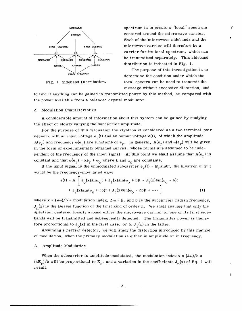
MICROWAVE spectrum is to create a "local" spectrum
CARRIER centered around the microwave carrier.
Each of the microwave sidebands and the
FIRST SIDEBAND FIRST SIDEBAND microwave carrier will therefore be a
carrier for its local spectrum, which can
SIDEBANDSU JSIDESANEBANDS be transmitted separately. This sidebandSIDEBANDS SIDEBANDS SSIDEBANDS
CARRIER CARRIER CARRIER distribution is indicated in Fig. 1.The purpose of this investigation is to
LOCAL SPECTRUMdetermine the condition under which the
Fig. 1 Sideband Distribution. local spectra can be used to transmit the
message without excessive distortion, and
to find if anything can be gained in transmitted power by this method, as compared with
the power available from a balanced crystal modulator.
2. Modulation Characteristics
A considerable amount of information about this system can be gained by studying
the effect of slowly varying the subcarrier amplitude.
For the purpose of this discussion the klystron is considered as a two terminal-pair
network with an input voltage er(t) and an output voltage e(t), of which the amplitude
A(er) and frequency w(er) are functions of e r. In general, A(er) and c(er) will be given
in the form of experimentally obtained curves, whose forms are assumed to be inde-
pendent of the frequency of the input signal. At this point we shall assume that A(er) is
constant and that w(er) = ker + o0 where k and o0 are constants.
If the input signal is the unmodulated subcarrier er(t) = Ersinbt, the klystron output
would be the frequency-modulated wave
e(t) = A J (x)sinot + Jl(x)sin(o + b)t - Jl(x)sin(wo - b)t
+ J 2 (x)sin(oo + 2b)t + J 2 (x)sin(wo - 2b)t + --- ] (1)
where x = ()/b = modulation index, A = k, and b is the subcarrier radian frequency.
Jn(x) is the Bessel function of the first kind of order n. We shall assume that only the
spectrum centered locally around either the microwave carrier or one of its first side-
bands will be transmitted and subsequently detected. The transmitter power is there-
fore proportional to Jo(x) in the first case, or to Jl(x) in the latter.
Assuming a perfect detector, we will study the distortion introduced by this method
of modulation, when the primary modulation is either in amplitude or in frequency.
A. Amplitude Modulation
When the subcarrier is amplitude-modulated, the modulation index x = (Acw)/b =
(kEr)/b will be proportional to E r , and a variation in the coefficients Jn(x) of Eq. 1 will
result.
-2-
_ � �_�_ __�
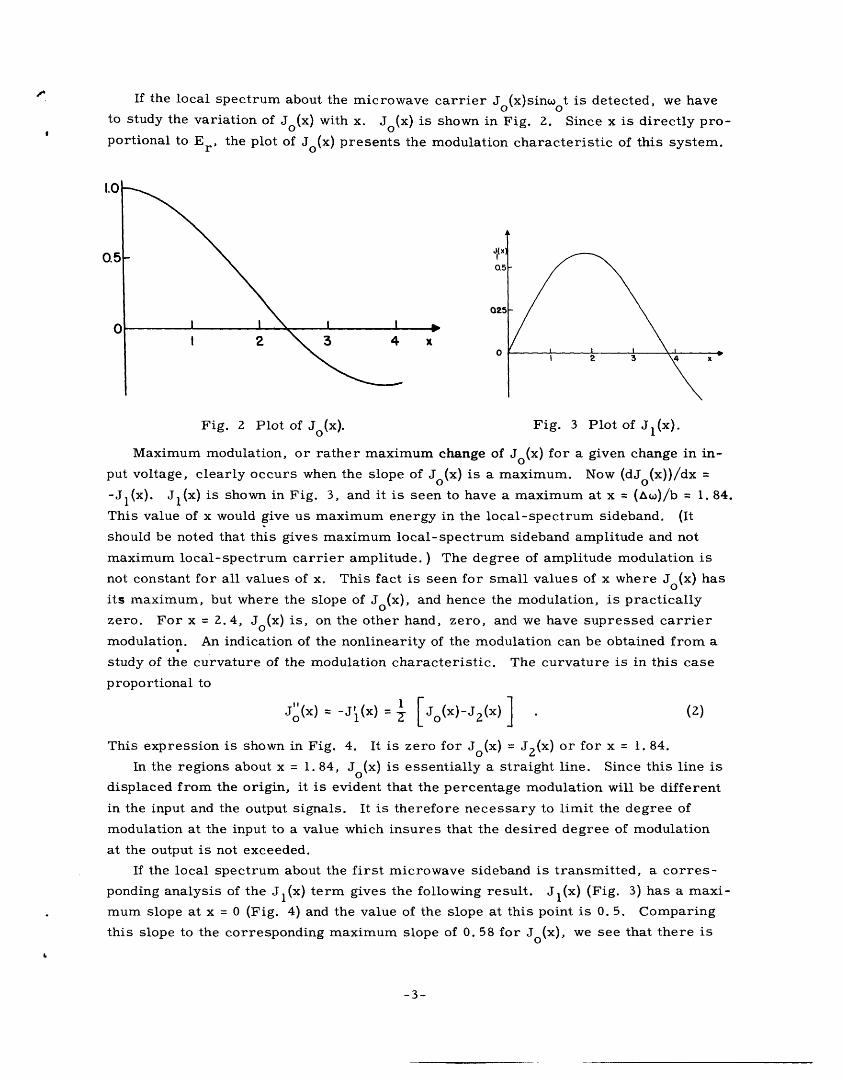
If the local spectrum about the microwave carrier J(x)sinwot is detected, we have
to study the variation of J(x) with x. J (x) is shown in Fig. 2. Since x is directly pro-
portional to Er, the plot of Jo(x) presents the modulation characteristic of this system.
Fig. 2 Plot of Jo(x). Fig. 3 Plot of J l(x)
Maximum modulation, or rather maximum change of Jo(x) for a given change in in-
put voltage, clearly occurs when the slope of Jo(x) is a maximum. Now (dJo(x))/dx =
-J 1 (x). J(x) is shown in Fig. 3, and it is seen to have a maximum at x = ()/b = 1. 84.
This value of x would give us maximum energy in the local-spectrum sideband. (It
should be noted that this gives maximum local-spectrum sideband amplitude and not
maximum local-spectrum carrier amplitude. ) The degree of amplitude modulation is
not constant for all values of x. This fact is seen for small values of x where Jo(x) has
its maximum, but where the slope of Jo(x), and hence the modulation, is practically
zero. For x = 2. 4, Jo(x) is, on the other hand, zero, and we have supressed carrier
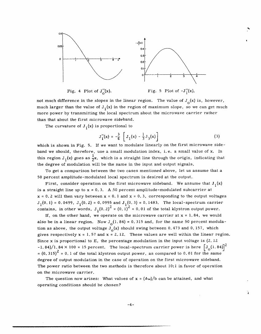
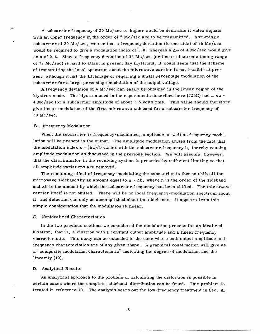
modulation. An indication of the nonlinearity of the modulation can be obtained from a
study of the curvature of the modulation characteristic. The curvature is in this case
proportional to
J!!(W -J WV2(x) (x) = [o(x)-J 2 (x) ] . (2)
This expression is shown in Fig. 4. It is zero for Jo(x) = J(x) or for x = . 84.
In the regions about x = 1.84, Jo(x) is essentially a straight line. Since this line is
displaced from the origin, it is evident that the percentage modulation will be different
in the input and the output signals. It is therefore necessary to limit the degree of
modulation at the input to a value which insures that the desired degree of modulation
at the output is not exceeded.
If the local spectrum about the first microwave sideband is transmitted, a corres-
ponding analysis of the Jl(x) term gives the following result. Jl(x) (Fig. 3) has a maxi-
mum slope at x = 0 (Fig. 4) and the value of the slope at this point is 0. 5. Comparing
this slope to the corresponding maximum slope of 0. 58 for Jo(x), we see that there is
-3-
0.51
Fig. 4 Plot of J(x). Fig. 5 Plot of -J"(x).0 1
not much difference in the slopes in the linear region. The value of Jo(x) is, however,
much larger than the value of J(x) in the region of maximum slope, so we can get much
more power by transmitting the local spectrum about the microwave carrier rather
than that about the first microwave sideband.
The curvature of Jl(x) is proportional to
J 1 (x) = [ J1lX) - J (x)] (3)
which is shown in Fig. 5. If we want to modulate linearly on the first microwave side-
band we should, therefore, use a small modulation index, i. e. a small value of x. In1
this region J(x) goes as x, which is a straight line through the origin, indicating that
the degree of modulation will be the same in the input and output signals.
To get a comparison between the two cases mentioned above, let us assume that a
50 percent amplitude-modulated local spectrum is desired at the output.
First, consider operation on the first microwave sideband. We assume that Jl(x)
is a straight line up to x = 0. 3. A 50 percent amplitude-modulated subcarrier at
x = 0. 2 will then vary between x = 0. 1 and x = 0. 3, corresponding to the output voltages
JI(0. 1) = 0. 0499, Jl(O. 2) = 0.0995 and J 1(0. 3) = 0. 1483. The local-spectrum carrier
contains, in other words, J 1 (0. 2)2 = (0. 1)2 = 0. 01 of the total klystron output power.
If, on the other hand, we operate on the microwave carrier at x = 1. 84, we would
also be in a linear region. Now Jo(1. 84) = 0. 315 and, for the same 50 percent modula-
tion as above, the output voltage Jo(x) should swing between 0. 473 and 0. 157, which
gives respectively x = 1. 57 and x = 2. 12. These values are well within the linear region.
Since x is proportional to E, the percentage modulation in the input voltage is (2. 12
-1. 84)/1. 84 x 100 = 15 percent. The local-spectrum carrier power is here [J 0o(. 84)]2
= (0. 315) = 0. 1 of the total klystron output power, as compared to 0. 01 for the same
degree of output modulation in the case of operation on the first microwave sideband.
The power ratio between the two methods is therefore about 10:1 in favor of operation
on the microwave carrier.
The question now arises: What values of x = (w)/b can be attained, and what
operating conditions should be chosen?
-4-
-ii'(
A subcarrier frequencyof 20 Mc/sec or higher would be desirable if video signals
with an upper frequency in the order of 5 Mc/sec are to be transmitted. Assuming a
subcarrier of 20 Mc/sec, we see that a frequencydeviation (to one side) of 36 Mc/sec
would be required to give a modulation index of 1.8, whereas a As of 4 Mc/sec would give
an x of 0. 2. Since a frequency deviation of 36 Mc/sec (or linear electronic tuning range
of 72 Mc/sec) is hard to attain in present day klystrons, it would seem that the scheme
of transmitting the local spectrum about the microwave carrier is not feasible at pre-
sent, although it has the advantage of requiring a small percentage modulation of the
subcarrier for a large percentage modulation of the output voltage.
A frequency deviation of 4 Mc/sec can easily be obtained in the linear region of the
klystron mode. The klystron used in the experiments described here (726C) had a A =
4 Mc/sec for a subcarrier amplitude of about 7. 5 volts rms. This value should therefore
give linear modulation of the first microwave sideband for a subcarrier frequency of
20 Mc/sec.
B. Frequency Modulation
When the subcarrier is frequency-modulated, amplitude as well as frequency modu-
lation will be present in the output. The amplitude modulation arises from the fact that
the modulation index x = ()/b varies with the subcarrier frequency b, thereby causing
amplitude modulation as discussed in the previous section. We will assume, however,
that the discriminator in the receiving system is preceded by sufficient limiting so that
all amplitude variations are removed.
The remaining effect of frequency-modulating the subcarrier is then to shift all the
microwave sidebandsby an amount equal to n · b, where n is the order of the sideband
and Ab is the amount by which the subcarrier frequency has been shifted. The microwave
carrier itself is not shifted. There will be no local frequency-modulation spectrum about
it, and detection can only be accomplished about the sidebands. It appears from this
simple consideration that the modulation is linear.
C. Nonidealized Characteristics
In the two previous sections we considered the modulation process for an idealized
klystron, that is, a klystron with a constant output amplitude and a linear frequency
characteristic. This study can be extended to the case where both output amplitude and
frequency characteristics are of any given shape. A graphical construction will give us
a composite modulation characteristic" indicating the degree of modulation and the
linearity (10).
D. Analytical Results
An analytical approach to the problem of calculating the distortion is possible in
certain cases where the complete sideband distribution can be found. This problem is
treated in reference 10. The analysis bears out the low-frequency treatment in Sec. A,
-5-
'4
��-1111111�-·-·1111·I� 11 -- --
and shows that no additional distortion of appreciable magnitude is introduced for high
modulating frequencies under normal conditions, i. e. for modulating frequencies in the
order of one-fourth of the subcarrier frequency.
3. Experimental Procedure
A. Description of the System
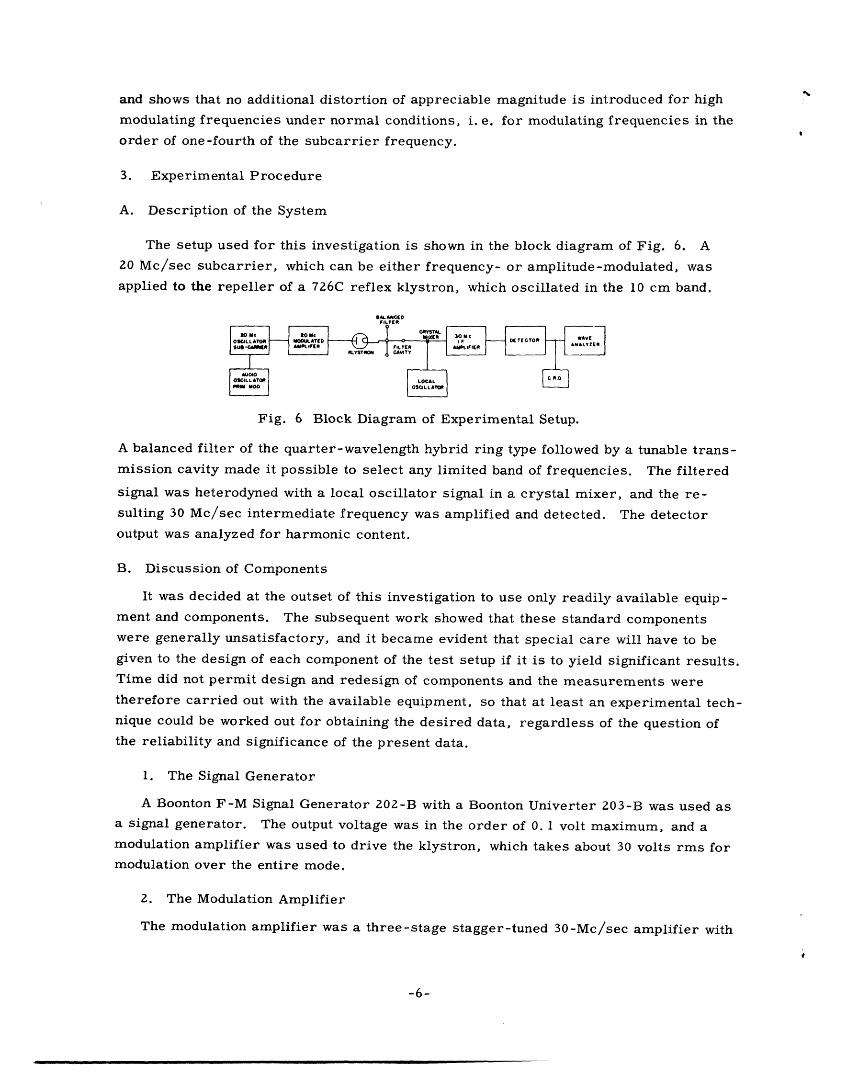
The setup used for this investigation is shown in the block diagram of Fig. 6. A20 Mc/sec subcarrier, which can be either frequency- or amplitude-modulated, was
applied to the repeller of a 726C reflex klystron, which oscillated in the 10 cm band.
Fig. 6 Block Diagram of Experimental Setup.
A balanced filter of the quarter-wavelength hybrid ring type followed by a tunable trans-
mission cavity made it possible to select any limited band of frequencies. The filtered
signal was heterodyned with a local oscillator signal in a crystal mixer, and the re-
sulting 30 Mc/sec intermediate frequency was amplified and detected. The detector
output was analyzed for harmonic content.
B. Discussion of Components
It was decided at the outset of this investigation to use only readily available equip-
ment and components. The subsequent work showed that these standard components
were generally unsatisfactory, and it became evident that special care will have to begiven to the design of each component of the test setup if it is to yield significant results.Time did not permit design and redesign of components and the measurements were
therefore carried out with the available equipment, so that at least an experimental tech-nique could be worked out for obtaining the desired data, regardless of the question ofthe reliability and significance of the present data.
1. The Signal Generator
A Boonton F-M Signal Generator 202-B with a Boonton Univerter 203-B was used asa signal generator. The output voltage was in the order of 0. 1 volt maximum, and amodulation amplifier was used to drive the klystron, which takes about 30 volts rms formodulation over the entire mode.
2. The Modulation Amplifier
The modulation amplifier was a three-stage stagger-tuned 30-Mc/sec amplifier with
-6-
__
a gain of about 1,000 and a bandwidth of 2 Mc/sec. A linear diode detector was incor-
porated in the design so that the linearity of the modulation envelope could be checked.
The amplifier was capable of delivering a linear output to the repeller of about 30 volts.
3. The Klystron
The klystron used in this investigation was a 726C reflex klystron which operated in
the 10 cm region. Since temperature variations cause the klystron to change its fre-
quency of oscillation, it was shielded from drafts. Any voltage picked up on the repeller
will modulate the klystron at a rate of about 0. 5 Mc/sec per volt rms. The importance
of shielding the tube electrically is therefore evident.
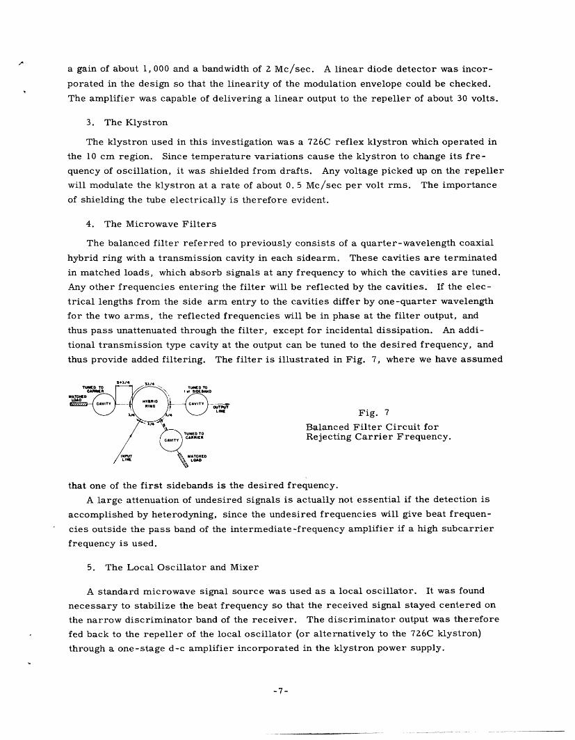
4. The Microwave Filters
The balanced filter referred to previously consists of a quarter-wavelength coaxial
hybrid ring with a transmission cavity in each sidearm. These cavities are terminated
in matched loads, which absorb signals at any frequency to which the cavities are tuned.
Any other frequencies entering the filter will be reflected by the cavities. If the elec-
trical lengths from the side arm entry to the cavities differ by one-quarter wavelength
for the two arms, the reflected frequencies will be in phase at the filter output, and
thus pass unattenuated through the filter, except for incidental dissipation. An addi-
tional transmission type cavity at the output can be tuned to the desired frequency, and
thus provide added filtering. The filter is illustrated in Fig. 7, where we have assumed
$ k/4 $X/4TNED TO /- TUNEO TO
CU~B I I/ f ,. oIEBAND
/ IN.UT% L o IdATGHLNW Fig. 7
Balanced Filter Circuit forCARRIER Rejecting Carrier Frequency.
that one of the first sidebands is the desired frequency.
A large attenuation of undesired signals is actually not essential if the detection is
accomplished by heterodyning, since the undesired frequencies will give beat frequen-
cies outside the pass band of the intermediate-frequency amplifier if a high subcarrier
frequency is used.
5. The Local Oscillator and Mixer
A standard microwave signal source was used as a local oscillator. It was found
necessary to stabilize the beat frequency so that the received signal stayed centered on
the narrow discriminator band of the receiver. The discriminator output was therefore
fed back to the repeller of the local oscillator (or alternatively to the 726C klystron)
through a one-stage d-c amplifier incorporated in the klystron power supply.
-7-
_ · __I - _

The mixer used a 1NZ1B crystal drawing about 0. 5 ma crystal current.
6. The Receiver
Three different receivers were used. The first measurements were made on a
Hallicrafters S-36 commercial receiver, preceded by a 30 Mc/sec intermediate-
frequency amplifier with a gain of about 500. The S-36 has.a 75 kc/sec (to one side)
wide discriminator. When the signal beat frequency was stabilized to the receiver
frequency, the receiver worked well for FM signals.
Hum and other extraneous signals, some of which are caused by vibrations, fre-
quency modulate the klystron. It is therefore highly desirable to use a much wider de-
viation than the 75 kc permitted by this standard broadcast receiver, so that the noise
can be made as small a fraction of the signal as possible. In this sense, the S-36 re-
ceiver is inadequate.
Frequency modulation with wide frequency deviation was detected in a wide-band
receiver, consisting essentially of an intermediate-frequency strip operating at 30
Mc/sec with a 6 Mc/sec bandwidth, followed by a discriminator of the tuned circuit type
operating above resonance. The intermediate-frequency strip working at full 120 db
gain is overdriven and therefore acts as a limiter.
Amplitude modulation of the subcarrier resulted, as mentioned before, in frequency
modulation of the klystron output with a frequency deviation of about one Mc/sec. For
detection of amplitude-modulated signals, the passband of the receiver should therefore
be several megacycles wide and have a flat response, so that the slopes of the passband
do not act as frequency discriminators, distorting the original amplitude-modulated
signal.
A 6 Mc/sec wide intermediate-frequency strip at 30 Mc/sec with a built-in plate
detector was used to detect the amplitude modulation. This receiver was, however,
not satisfactory for this use. The gain was controlled by adjusting the grid bias on the
first two stages, a procedure which resulted in poor envelope linearity for the large
gain reductions necessary with this 120 db amplifier. An attenuator box was inserted
between the mixer output and the amplifier input, so that the amplifier input could be
kept constant at the best value for linear operation, but all indications were that the
amplifier linearity was not good. The attenuator box was also used to determine the
level of the received signal.
7. Distortion Measuring Equipment
A General Radio Wave Analyzer was used to measure the distortion in the detected
signal. The wave analyzer could handle frequencies up to 15 kc/sec, which meant that
the useful range of modulation frequencies for distortion measurements was limited to
about 5 kc/sec.
-8-
I_ ____ ___ _ _ _ __ _
C. Results of the Meaurements
1. Shift of the Center Frequency
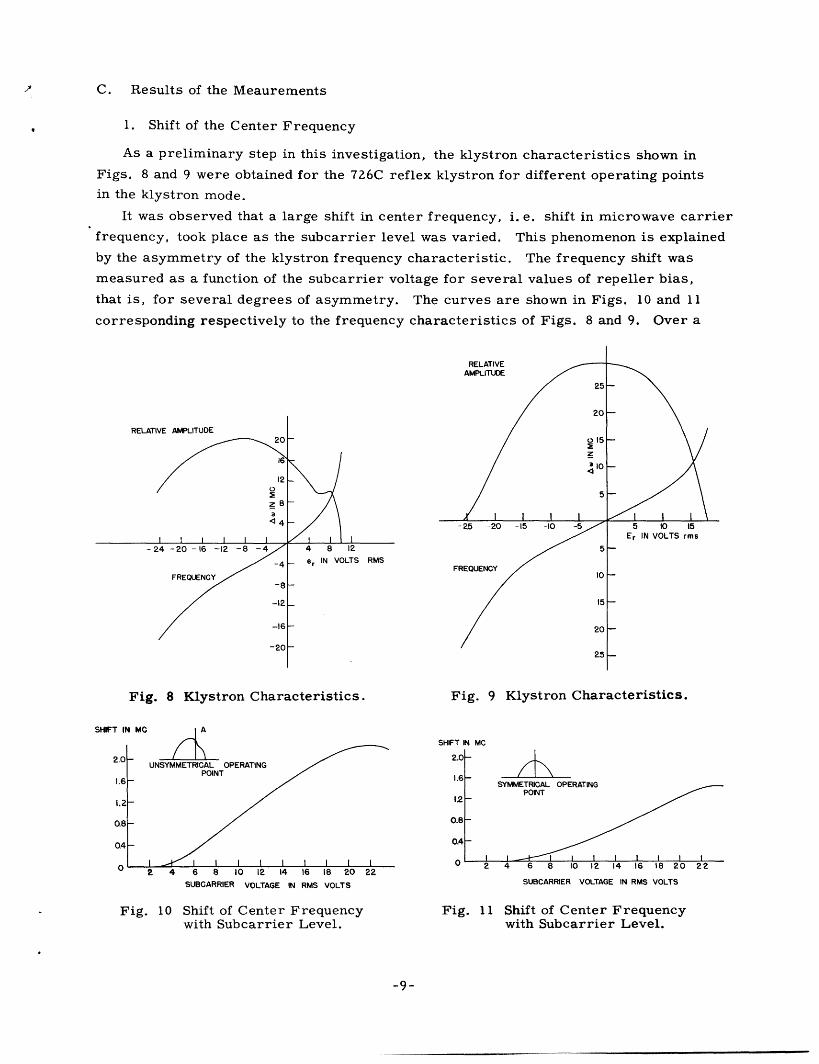
As a preliminary step in this investigation, the klystron characteristics shown in
Figs. 8 and 9 were obtained for the 726C reflex klystron for different operating points
in the klystron mode.
It was observed that a large shift in center frequency, i. e. shift in microwave carrier
frequency, took place as the subcarrier level was varied. This phenomenon is explained
by the asymmetry of the klystron frequency characteristic. The frequency shift was
measured as a function of the subcarrier voltage for several values of repeller bias,
that is, for several degrees of asymmetry. The curves are shown in Figs. 10 and 11
corresponding respectively to the frequency characteristics of Figs. 8 and 9. Over a
RELATIVE AMPLITUDE
er IN VOLTS RMS
RELATIVEAMPLITUDE
25
20
0 15I
/10
5
1 I I I-25 -20 -15 -10 -5
5
FREQUENCY10I
15
20
25
Fig. 8 Klystron Characteristics. Fig. 9 Klystron Characteristics.
A ASHIFT IN M(
UNSYMMETRICAL OPERATINGPOINT I I I
2.0
1.6
12
0.8
0.4 KL. I lMM I rlT I I I I I I
2 4 6 8 10 12 14 16 18 20
SUBCARRIER VOLTAGE IN RMS VOLTS
Fig. 11 Shift of Center Frequencywith Subcarrier Level.
-9-
I - I I5 10 15
Er IN VOLTS rms
SHIFT IN MC
2.0
1.6
1.2
0.8
0.4
2 4 6 8 10 12 14 16 18 20 22SUBCARRIER VOLTAGE IN RMS VOLTS
Fig. 10 Shift of Center Frequencywith Subcarrier Level.
22. .. . . . . . . . .B . . . . . . . . . . .
_ II_ I�____
I
_
I
-
C
Iv
CV·I·ICT�I�III n�C�ITI�.I�

limited region these curves are fairly linear, and it was therefore thought that this effect
could be used by amplitude modulating the subcarrier and frequency detecting the micro-
wave carrier or its sidebands, which shift by the same amount. Measurements made on
the wideband discriminator indicated about 3, 2 and 1 percent second harmonic distor-
tion for respectively 50, 30 and 15 percent amplitude modulation of the subcarrier when
the subcarrier level was chosen to give minimum distortion.
2. Frequency Modulation of Subcarrier, Frequency Detection
It was shown in Sec. 2 that when the subcarrier is frequency-modulated, only the
microwave sidebands have a frequency-modulated local spectrum. This fact was veri-
fied experimentally, and the distortion in the local spectrum about the first microwave
sideband was measured for a modulation frequency of 1,000 cps and 400 cps. The
results are plotted on Fig. 12.
IE - new Fig. 12 Frequency Modulation-Frequency DetectionUsing Narrow-Band Discriminator.
The Hallicrafters receiver was used. The frequency deviation was 60 kc/sec for
curves A and B, and 40 kc/sec for curve C. It is noticed that a reduced frequency de-
viation reduces the distortion; this effect can be attributed to the fact that the 40 kc/sec
deviation leaves some leeway for the center frequency to shift up or down and still keep
the deviation within the linear part of the discriminator curve.
The data of Fig. 12 were taken for the unsymmetrical operating point A in Fig. 8.
A corresponding run was made at 60 kc/sec deviation for the more symmetrical
operating point B (Fig. 9). The distortion in this case was less than 1 percent over the
whole range of modulating voltages up to 25 volts. These data should be considered
rather inconclusive since some amplitude modulation accompanied the frequency modu-
lation at the repeller, due to imperfection in the passband of the modulation amplifier.
For each setting an attempt was made to minimize the amplitude modulation by changing
the subcarrier frequency slightly until a minimum of amplitude modulation was detected
by the diode detector which was built into the amplifier. Since even a slight amplitude
modulation causes a frequency modulation comparable to the one intentionally introduced,
the distortion would vary by a factor of two or three as the tuning was changed slightly.
The plotted data are the ones which were believed to correspond to the minimum
amount of "parasitic" amplitude modulation at the modulator output.
It seemed to be impossible to eliminate a "parasitic" amplitude modulation causing
a frequency modulation of about 15-20 kc/sec at 25 volts subcarrier amplitude.
These results show clearly that a limiter is necessary, following the amplification
of the frequency-modulated subcarrier.
The distortion measured on the wide-band discriminator for 210 kc/sec and 150
kc/sec deviation with a modulation frequency of 1 kc/sec is plotted on Fig. 13.
-10-
_ _ __I � �I�__
; ' Fig. 13 Frequency Modulation-Frequency DetectionUsing Wide-Band Discriminator.
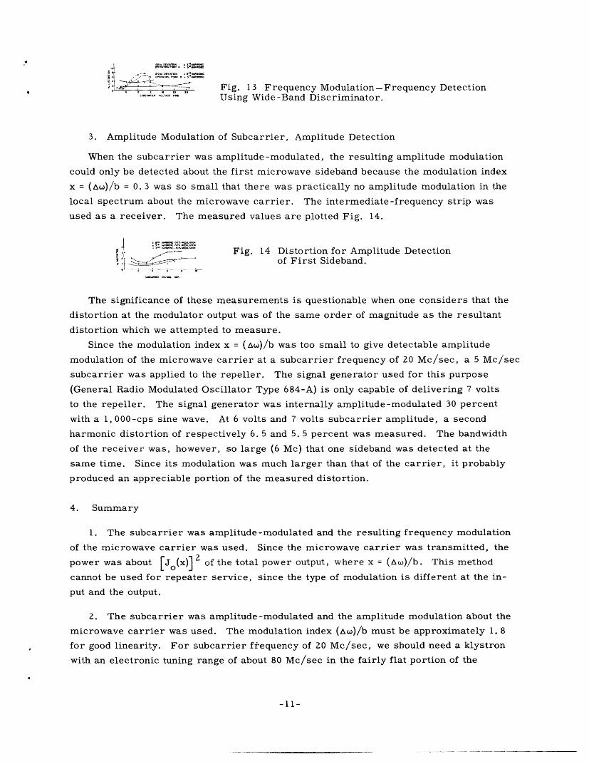
3. Amplitude Modulation of Subcarrier, Amplitude Detection
When the subcarrier was amplitude-modulated, the resulting amplitude modulation
could only be detected about the first microwave sideband because the modulation index
x = (Ac0)/b = 0. 3 was so small that there was practically no amplitude modulation in the
local spectrum about the microwave carrier. The intermediate-frequency strip was
used as a receiver. The measured values are plotted Fig. 14.
Fig. 14 Distortion for Amplitude Detectionof First Sideband.
The significance of these measurements is questionable when one considers that the
distortion at the modulator output was of the same order of magnitude as the resultant
distortion which we attempted to measure.
Since the modulation index x = (Aw)/b was too small to give detectable amplitude
modulation of the microwave carrier at a subcarrier frequency of 20 Mc/sec, a 5 Mc/sec
subcarrier was applied to the repeller. The signal generator used for this purpose
(General Radio Modulated Oscillator Type 684-A) is only capable of delivering 7 volts
to the repeller. The signal generator was internally amplitude-modulated 30 percent
with a 1, 000-cps sine wave. At 6 volts and 7 volts subcarrier amplitude, a second
harmonic distortion of respectively 6. 5 and 5. 5 percent was measured. The bandwidth
of the receiver was, however, so large (6 Mc) that one sideband was detected at the
same time. Since its modulation was much larger than that of the carrier, it probably
produced an appreciable portion of the measured distortion.
4. Summary
1. The subcarrier was amplitude -modulated and the resulting frequency modulation
of the microwave carrier was used. Since the microwave carrier was transmitted, the
power was about [Jo(x)] 2 of the total power output, where x = (Aw)/b. This method
cannot be used for repeater service, since the type of modulation is different at the in-
put and the output.
2. The subcarrier was amplitude-modulated and the amplitude modulation about the
microwave carrier was used. The modulation index (A)/b must be approximately 1.8
for good linearity. For subcarrier frequency of 20 Mc/sec, we should need a klystron
with an electronic tuning range of about 80 Mc/sec in the fairly flat portion of the
-11-
�-^-I -- "-I
amplitude curve, which means an improvement by a factor of three or four compared to
the electronic tuning range of the 726C.
A subcarrier frequency in the order of 3 to 4 Mc/sec will allow us to operate a 726C
or a similar tube at the optimum value of modulation index. The useful power output by
this method was calculated to be about 0. 1 of the total klystron output, requiring a klys-
tron output of about 250 Mw to equal the output of the crystal modulator. The degree of
modulation is smaller at the input than at the output, a fact which seems disadvantageous
for repeater service.
3. The subcarrier was amplitude-modulated and the amplitude modulation about the
first microwave sideband was used. A small modulation index of 0. 2 to 0. 3 is needed,
corresponding to 8 to 10 Mc/sec peak-to-peak tuning range for a 20 Mc/sec subcarrier,
and this range can easily be obtained with a tube like the 726C klystron.
The degree of modulation is the same in the output as in the input. The power level
is in the order of 0. 01 of the total klystron power output, which therefore must be about
2. 5 watts to make the modulated output equal to that of a crystal modulator.
4. The subcarrier was frequency-modulated and the frequency modulation about the
first microwave sideband was used. The measurements indicated that this method gave
the lowest distortion with a measured value not exceeding one percent. The fraction of
the total klystron output power available is [Jo(x)] 2, which has a maximum of 0. 34
at x = ()/b = 1. 84. With a 20 Mc/sec peak-to-peak tuning range and a 20 Mc/sec
subcarrier frequency, that is for x = 0. 5, the output power will be 0. 06 of the total
klystron output. This method of modulation appeared to be the most promising of those
studied here.
The experimental results obtained here are considered inconclusive as far as a
reliable evaluation of the various methods is concerned. No general references will
therefore be made to the experimental material, other than to state that it confirms the
analytical results within the limits of accuracy achieved.
-12-
� _I __ I _�_ _�_I�_ _ __
References
1. H. T. Friis: Microwave Repeater Research, B. S. T. J., 27, 183, April, 1948
2. C. L. Cuccia: The Electron Coupler-A Developmental Tube for AmplitudeModulation and Power Control at Ultra-High Frequencies, RCA Rev. 10, No. 2,270, 1949
3. L. D. Smullin, W. N. Coffey: The Use of Silicon Point-Contact Rectifiers forModulating Microwave Signals, Technical Report No. 83, Research Laboratoryof Electronics, M.I. T., November, 1948
4. G. Collins: Microwave Magnetrons, Radiation Laboratory Series No. 6, McGraw-Hill, New York, 1948
5. L. P. Smith, C. I. Shulman: Frequency Modulation and Control by ElectronBeams, Proc. I. R.E. 35, No. 7, 644, July, 1947
6. G. R. Kilgore, C. I. Shulman, J. Kursham: A Frequency-Modulated Magnetronfor Super-High Frequencies, Proc. I. R. E. 35, No. 7, 657, July, 1947
7. V. Learned: The Klystron Mixer Applied to Television Relaying, Proc. I. R. E.38, No. 9, 1033, September, 1950
8. W. H. Foster: 6, 000 Mc Television Relay System, Electronics, 22, 80,January, 1949
9. G. G. Gerlach: A Microwave Relay Communication System, RCA Rev. 7, No. 4,576, December, 1946
10. J. Jensen: Subcarrier Modulation of a Reflex Klystron, Master's Thesis,Department of Electrical Engineering, M. I. T., 1949
-13-
�_11_-111*11 11_ --1__1_1_^___-___� -- I

I _