sub soil investigation & recommondations in … investigation... · the standard penetration...
TRANSCRIPT

Client:
Commissioner, AP CRDA, Vijayawada
GOVERNMENT OF ANDHRAGOVERNMENT OF ANDHRAGOVERNMENT OF ANDHRAGOVERNMENT OF ANDHRA PRADESHPRADESHPRADESHPRADESH
CAPITAL REGION DEVELOPMENT AUTHORITYCAPITAL REGION DEVELOPMENT AUTHORITYCAPITAL REGION DEVELOPMENT AUTHORITYCAPITAL REGION DEVELOPMENT AUTHORITY
1.
REPORT ON
““““SUB SOIL INVESTIGATION & SUB SOIL INVESTIGATION & SUB SOIL INVESTIGATION & SUB SOIL INVESTIGATION &
RECOMMONDATIONSRECOMMONDATIONSRECOMMONDATIONSRECOMMONDATIONS””””
IN AP CAPITAL CITY SEED AREAIN AP CAPITAL CITY SEED AREAIN AP CAPITAL CITY SEED AREAIN AP CAPITAL CITY SEED AREA
Survey done by
Sri Saladi Sri Hari
CONTRACTOR, PERAVALI, WG DISTRICT
Ph: +91 9848364246
Testing done by
DEPARTMENT OF CIVIL ENGINEERING
V R SIDDHARTHA ENGINEERING COLLEGE
VIJAYAWADA
REPORT ON
SUB SOIL INVESTIGATION IN
ANDHRA PRADESH STATE SEED CAPITAL AREA
1. BACKGROUND & NEED:
The Government of Andhra Pradesh has envisaged development of a world class
people’s capital which is located in between the cities of Vijayawada and Guntur in an
extent of about 8,420 Sq.km. The aspiration is to create a vibrant, diverse and modern
Capital City, which is a glowing pride for all the people of Andhra Pradesh and magnet
for industries development. It should synthesize the best features of urban planning,
sustainability and effective governance to create an exclusive, highly livable and world
class eco system.
Andhrapradesh Capital Region Development Authority (CRDA) is enacted by the
Government of Andhra Pradesh through AP CRDA Act, 2014 (Act No: 11 of 2014) to
establish a New Capital ‘Amaravathi’ for the residual state of Andhra Pradesh.
AP CRDA is responsible for planning and regional development authority responsible for
preparation and approval of the Masterplan of the region. The Capital City is envisaged
to be developed as a Smart, Blue-Green and Sustainable City.
It is proposed in the masterplan to construct world class and many iconic structures
in the area, which necessitated the AP CRDA to explore the characteristics of the
sub-soil strata in the proposed seed capital area to plan, design and to execute the
construction activity.
Accordingly, the work of “Sub Soil Investigation in A P Seed Capital Area” with an
estimated cost of Rs. 7.60 Lakh is proposed and awarded to Sri. Saladi Sri Hari,
Contractor, Peravali, West Godavari District on tender basis. The agency is assigned
with the following.
• Soil boring of 150 mm diameter upto 15m depth.
• Collection of undisturbed and disturbed soil samples from the bores.
• Conducting Standard Penetration Test (SPT) at regular intervals within the
bores.
• Testing of undisturbed and disturbed soil samples collected from the bores in
the laboratory.
• Recommendation of suitable bearing capacity and type of foundation
for proposed structures.
2. LOCATION:
The area under scope of this work is spread over in 16.50 Sq. KMs in the village
limits of Lingayapalem, Uddnadarayunipalem and Thallayapalem in Thullur Mandal of
Guntur District. The area under scope is formed with Grid and the following points are
identified for conducting the Sub Soil Exploration.
I. A1, A2, A3, A4, A5, A6, A7 and A8.
II. B1, B2. B3, B4, B5, B6, B7, and B8.
III. C1, C2, C3, C4, C5, C6, C7, and C8.
IV. I1, I2.
The soil samples are extracted at specified locations and got tested in
Velagapudi Ramakrishna Siddhartha Engineering College, Vijayawada. This report contains
the results of field and laboratory tests. Recommendations on Bearing Capacity of soil and
its type, Engineering properties & type of foundation.
3. FIELD INVESTIGATION PROCEDURE:
The Sub-soil investigation was carried out to determine…
• Sequence and extent of each soil and rock stratum likely to be affected by the
proposed work.
• Nature of each stratum and Engineering properties of soil which may affect the
mode of construction of the proposed structures and their foundation.
• Location of ground water table and possible corrosive effects of soil and water on
foundation materials.
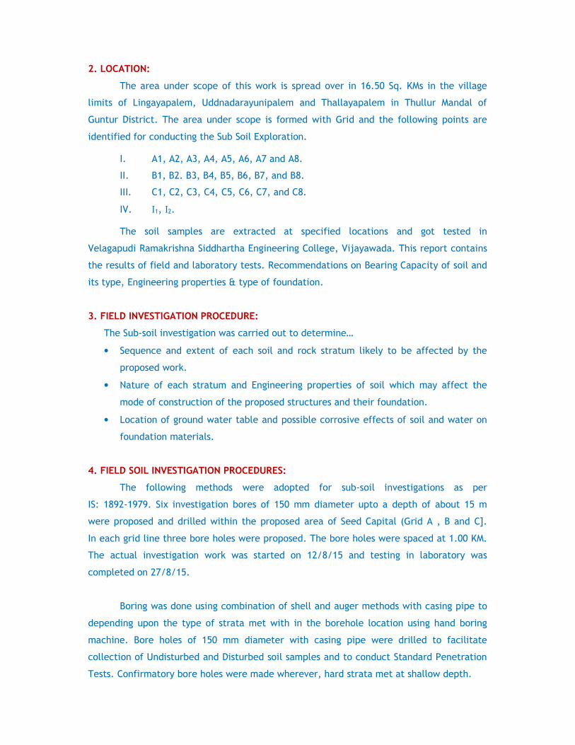
4. FIELD SOIL INVESTIGATION PROCEDURES:
The following methods were adopted for sub-soil investigations as per
IS: 1892-1979. Six investigation bores of 150 mm diameter upto a depth of about 15 m
were proposed and drilled within the proposed area of Seed Capital (Grid A , B and C].
In each grid line three bore holes were proposed. The bore holes were spaced at 1.00 KM.
The actual investigation work was started on 12/8/15 and testing in laboratory was
completed on 27/8/15.
Boring was done using combination of shell and auger methods with casing pipe to
depending upon the type of strata met with in the borehole location using hand boring
machine. Bore holes of 150 mm diameter with casing pipe were drilled to facilitate
collection of Undisturbed and Disturbed soil samples and to conduct Standard Penetration
Tests. Confirmatory bore holes were made wherever, hard strata met at shallow depth.

4.1 Drilling:
Each borehole of 150mm diameter is drilled up to the depth of 15.0m. Where ever
caving of the borehole occurred, casing was used to keep the borehole stable. The work
was in general accordance with IS: 1892-1979. The borehole is located at 1 Km interval at
the proposed seed capital.
4.2. Distributed Samples:
Disturbed but representative soil samples were collected, logged labeled and
placed in polythene bags.
4.3. Undisturbed Samples:
Undisturbed soil samples are collected in 100 mm diameter thin walled sampler
(Shelby tube) from the borehole. The sampler used for the sampling had smooth surface
and appropriate area ratio and cutting edge angle thereby minimizing disturbance of soil
during sampling. Samples are logged and labeled properly and transfer to the laboratory
for further testing.
4.4. Method of Sampling:
Sampler is coupled together with a sampler head to form a sampling assembly. The
sampler head provide a non-flexible connection between the sampling tube and the drill
rods. Vent holes are provided in the sampler head to allow escape of water from the top
of sampler tube during penetration. The sampling tubes are made free from dust and rust.
Coating of oil is applied on both sides to obtain the undisturbed samples in best possible
manner.
The sampler is then lowered inside the bore hole on a string of rods and driven to a
predetermined level. On completion of driving the sampler is first rotated within the
borehole to shear the soil sample at bottom and then pulled out. Upon removal of the
sampling tubes, the length of sample in the tube is recorded. The disturbed material in
the upper end of the tube, if any, is completely removed before sealing.
The soil at the lower end of the tube is trimmed to a distance of about 10 to 20
mm. After, Cleaning and inserting an impervious disc at each end, both ends are sealed.
The empty space in the sampler, if any, is filled with the moist soil, and the ends covered
with wall and tight wrapper. The identification mark is then made on each sample.

4.5 Standard Penetration Test (SPT Test):
The standard penetration tests are conducted in each bore as per IS: 2131:
1981(Reaffirmed 2002). The split spoon sampler resting on the bottom of bore hole is
allowed to sink under its own weight, then the split spoon sampler is seated 15 cm with
the blow of hammer falling through 750mm. the driving assembly consists of a driving head
and a 63.5 kg weight. It is ensured that the energy of the falling weight is not reduced by
friction between the drive weight and the guides or between ropes. The rods to which the
sampler is attached for driving are straight, tightly coupled and straight in alignment.
Thereafter the split spoon sampler is further driven by 30cm. The number of blow required
to drive each 15cm penetration is recorded. The first 15cm of drive considered as seating
drive. The total blows required for the second and third 15cm penetration is termed as a
penetration resistance- N value. The N-Values for each bore hole are given in bore logs.
A Strata is considered to be hard, when the ‘N’ Value i.e. the number of blows
required for 300 mm penetration of the SPT spoon beyond a seating penetration of 150
mm in the strata is more than 50 ( Clause 3.3.3 of IS:3132-1981). If the penetration of the
spoon is less than 300 mm more than 50 blows, the N value is written as N>50. All the
results obtained from the field operations are shown in the log of bore (Figure: 1 - 9).
4.6 Water Table:
The depth of water table at the end of boring is observed. 5. LABORATORY TESTS:
The laboratory tests on soil samples were started immediately after the receipt of the
same in the laboratory. Following laboratory tests are carried out to determine the
physical and engineering properties of undistributed and disturbed soil samples.
1. Dry density and moisture content - (IS 2720 part – 2 & 29)
2. Particle size analysis – (IS 2720 part – 4 1985)
3. Atterberg’s limit – (IS 2720 part 5 – 1985)
4. Specific gravity – (IS 2720 part – 3/sec2 1980)
5. Shear test – (IS 2720 part-11 1986)
6. Consolidation test – (IS 2720 part – 15 1986)
7. Free swell and Swell pressure test - (IS 2720 part – 40 1977, part-41 1977))
All laboratory tests are carried out as per the respective Indian Standards.

5.1 Field Dry Density & Natural Moisture Content:
The weight of undistributed soil sample with sampler (Shelby tube) is determined
after removing paraffin wax and loose soil. The total length of soil sample recovery is
determined after deducting empty length from the total length of sampler. The volume of
soil mass retained in sampler is thus determined from the known inside diameter of
sampler and total length of soil mass. The soil mass is then removed and the average
moisture content is determined by keeping the soil sample along with crucible in oven at
100-105 degree centigrade for 24 hours. The empty weight of the sampler is then found
out. From the total weight of sampler with soil mass, the weight of empty sampler is
deducted. The field density is then found out as follows.
Field density (bulk),γt = weight of soil mass / volume of soil mass
And, Field dry density, γd = γt / (1+w)
Where ‘w’ is water content.
5.2 Particle Size Analysis:
The sieve analysis is carried out in accordance with IS: 2720 (Part 4, 1985). The
results are presented in the form of Grain size distribution curve.
Representative soil sample is obtained from the bulk soil sample collected or
received from site by method of coning and quartering. Quantity of soil taken will be
dependent on the maximum size of particle size present in the soil. Sieve analysis is
conducted in two parts.
1) Soil fraction retained on 4.7Smm ISS:
Soil portion retained on 4.75 ISS is weighed. The sample is then separated into
various fractions by Sieving through the following sieves: 100, 75, 19 and 4.75 mm ISS
While sieving through each sieve, sieve is agitated so that sample rolls in irregular
motion over the sieve, at no time the particles are pushed through; Care is also taken to
see that no individual soil particles are broken, though particles adhering one another are
rubbed by rubber pestle when required. Care is also taken not to over load the sieve
beyond the permitted maximum load for respective sieve.

The mass of the material retained on each sieve is recorded The percentage of soil
retained on each sieve is then calculated on the basis of the total mass of soil taken and
from these results, the percentage passing through each sieve is calculated.
2) Soil fraction passing 4.75 ISS:
The portion of the soil passing 4.75mm ISS is oven dried at 105 to 110 centigrade.
The portion is coned & quartered to obtain required representative quantity of the
material. The material is weighed and placed in tray/bucket filled with water for soaking
and loosening the adhered cohesive materials. The soaked soil specimen is then washed on
75 micron IS Sieve until the water passing the sieve is almost clear. The material retained
on 75 micron IS Sieve is then transferred in a tray, dried in oven.
Sieve analysis is then conducted on a nest of sieves (viz. 2 mm, 425 and 75 micron
ISS) either by hand or by using mechanical sieve shaker. The fraction retained on each of
the sieves is weighed separately and masses recorded. Cumulative mass of soil fraction
retained on each sieve is then calculated. The combined gradation on the basis of the
total sample taken for analysis is finally calculated.
5.3 Atterberg's Limits:
For fine grained soils, consistency limits are important in addition to natural
moisture content. The Consistency Limits are Liquid Limit, Plastic Limit and Shrinkage
Limit. Liquid and plastic limits are determined by using procedure given in IS: 2720.
The Liquid Limit test was conducted on disturbed soil samples using Cassagrande’s
Liquid Limit device and grooving tool. The moisture content of the soil paste
corresponding to number of blows required to close the grove made by the grooving tool in
the apparatus is determined. The liquid limit of the soil which corresponds to the moisture
content of a paste which would give 25 blows is determined from the flow curve.
For determination of plastic limit, a soil sample weighing at least 20 gm from the
soil sample passing 425micron IS sieve is thoroughly mixed with water such that it can be
easily moulded with fingers. A ball is formed with about 8 to 10 gm of this soil and is
rolled between the fingers and the glass plate with just sufficient pressure to roll the mass
into a thread of uniform diameter of 3mm throughout its length. The soil is then kneaded
together to a uniform mass and rolled again. The process is continued until the thread
crumbles. The pieces of crumbled soil thread are collected and moisture content is
determined and reported as plastic limit.

5.4 Specific Gravity:
The specific gravity of soil solids is determined by a 50ml density bottle. The
weight (Wl) of the empty dry bottle is taken first. A sample of oven-dried soil about 10-20
g cooled in a desiccator, is put in the bottle, and weight (W2) of the bottle and the soil is
taken. The bottle is then filled with distilled water gradually removing the entrapped air
either by applying vacuum or by shaking the bottle. The weight (W3) of the bottle, soil
and water (full up to the top) is then taken. Finally the bottle is emptied completely and
thoroughly washed and clean water is filled to the top and the weight (W4) is taken.
Specific Gravity (G) = (W2 – W1) ------------------------- (W2 – W1) - (W2 – W4)
5.5 Shear Test:
Tri-axial (undrained) tests are carried out to determine the shear parameters. The
shear tests are carried out in accordance with IS: 2720 (pt. X, XI, XII and XIII) on saturated
samples. For unconsolidated undrained tri-axial compression test, the undisturbed soil
specimen having diameter 38 mm and height to diameter ration 2 is prepared and placed
on the pedestal of the tri-axial cell. The cell is then assembled with the loading ram and
then placed in the loading machine. The cell fluid is admitted to the cell and the pressure
is raised to the desired value. An initial reading of the gauge measuring axial compression
of the specimen is recorded. The test is then commenced and sufficient number of
simultaneous readings of load and compression measuring gauge being taken. The test is
continued until the maximum value of the stress has been passed or until an axial strain of
20 per cent has been reached. Additional tests are carried out on identical specimen at
confining pressure of 1 kg/cm2
, 2 kg/cm2
and 3 kg/cm2
. The shear parameters are obtained
from the plot of Mohr circles.
Direct Shear Test is carried out using shear box with the specimens
(60mm x 60mm). Specimen with plain grid plate at the bottom of the specimen and plain
grid plate at the top of the specimen is fitted into position in the shear box housing and
assembly placed on the load frame. The serrations of the grid plates are kept at right
angle to the direction of shear. The loading pad is kept on the top grid plate. The required
normal stress is applied and the rate of longitudinal –displacement/shear stress application
so adjusted that no drainage can occur in the sample during the test (1.25mm/min). The
upper part of the shear box is raised such that a gap of about 1mm is left between the two
parts of the box. The test is conducted by applying horizontal shear load to failure or to 20

percent longitudinal .displacement whichever occurs first. The test is repeated on
identical specimens.
5.6 Consolidation Test:
The consolidation tests were carried out on undisturbed soil specimen in order to
determine the settlement characteristics of soil at different depths. The tests were
conducted in accordance to IS: 2720 (Pt-XV).
An undisturbed soil specimen is extruded to the consolidation ring of 60mm
diameter. The edge is trimmed carefully such that the sample flushes with the top and
bottom edges of the ring. The thickness of the specimens measured and the weight is
recorded. The bottom porous stone is then centered on the base of the consolidation cell.
The specimen is placed centrally between the bottom porous stone and the upper
porous stone. A filter paper is provided in-between specimen and porous stones. Then the
loading cap is p1aced on the top. The consolidometer is placed .in position jn the loading
device and suitably adjusted. The dial gauge is then clamped into position for recording
the relative movement between the base of the cell and the loading cap. A seating
pressure of 0.05 kg/cm2
is applied to the specimen. The cell is kept filled with water.
After 24 hours the test is continued using a loading sequence on the soil specimen of 0.25,
0.5, 1.0, 2.0, 4.0 and 8.0 kg/cm2. For each loading increment after application of load,
readings of the dial gauge is taken using time sequence 0, 0.25, 1,
2.25,2,.6.25,9,16,25,36,49 upto 24 hrs. From the observations of all incremental
pressure, void ratio versus log (pressure) curve is obtained. The slope of the straight line
portion is designated as compression index Cc.
5.7 Differential Free Swell Test:
In order to determine the swelling characteristics of the soil, differential free swell
test is carried out on oven dried soil sample. 10 gm passing through 425 micron is poured
in two100 ml graduated cylinders. One cylinder was filled with distilled water and another
with kerosene up to 100 ml mark. After removal of entrapped air, sample was allowed
sufficient time to attain equilibrium state of volume. The final volume of soil in each
cylinder was recorded.
Soil volume in water -soil volume in kerosene DFS = -----------------------------------------------------
Soil volume in kerosene
SUB SOIL PROFILES
A -1, A -2, A-3
B -1, B -2, B-3
C -1, C -2, C-3

6 SUB SOIL PROFILES
The Sub soil profile at the bore hole locations, based on the identification of soil
samples and the results of tests (both field and laboratory) are indicated in Figure: 1 -9. The
idealized design soil parameters are given in Table 1, 3, 5, 7, 9, 11, 13 and 15.
6.1 Bore Hole Number: Grid A- 1 Ground Water Level = 2.60 m
Depth Below
G.L.(metres)
Soil Type and Classification Recorded SPT
“N” Value
0.00 – 1.70 Brownish plastic silty clay [MH - CH] qc = 84 kN/m2
1.70 – 3.00 Brownish clayey silty sand [SC-SM] 24
3.00 – 4.00 Brownish sandy silty clay [MH - CH] qc= 174 kN/m2
4.00 – 5.00 Brownish sandy silty clay [MH - CH] 26
5.00 – 5.70 Brownish sandy silty clay [MH - CH] qc = 224 kN/m2
5.70 – 8.00 Yellowish brown silty fine to medium sand [SM-SP] 35, 44
8.00 – 15.00 Yellowish brown silty fine to medium sand [SM-SP] >50
15.00 – 15.45 Yellowish brown silty fine to medium sand [SM-SP] 44
6.2 Bore Hole Number: Grid A- 2 Ground Water Level = 2.20 m
Depth Below
G.L.(metres)
Soil Type and Classification Recorded SPT
“N” Value
0.00 – 2.00 Brownish plastic silty clay [MH - CH] qc = 88 kN/m2
2.00 – 3.00 Brownish plastic silty clay [MH - CH] 11
3.00 – 5.00 Yellowish brown silty medium to fine sand [SM-SP] 25, 37
5.00 – 9.00 Yellowish brown fine to medium sand [SP] 34,42,43,48
9.00 – 15.45 Yellowish brown fine to medium sand [SP] >50
6.3 Bore Hole Number: Grid A- 3 Ground Water Level = 3.80 m
Depth Below
G.L.(metres)
Soil Type and Classification Recorded SPT
“N” Value
0.00 – 2.00 Brownish plastic silty clay [MH - CH] qc =128 kN/m2
2.00 – 3.50 Brownish clayey silty sand [SC-SM] 37
3.50 – 5.00 Yellowish brown plastic silty clay [MH-CH] 42
5.00 – 8.00 Yellowish brown fine to medium sand [SP] 40, 47
8.00 – 10.0 Yellowish brown silty fine to medium sand [SM-SP] >50
10.00– 15.45 Yellowish brown fine to medium sand [SP] >50
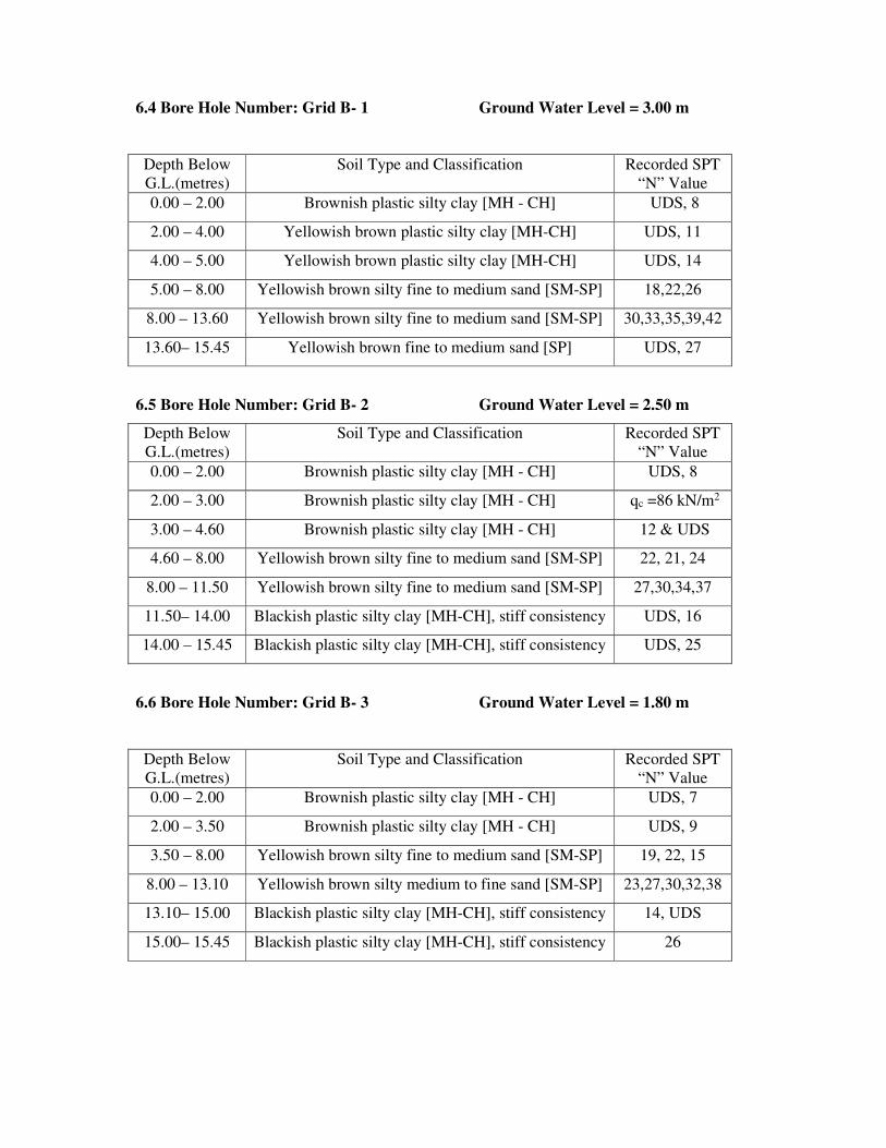
6.4 Bore Hole Number: Grid B- 1 Ground Water Level = 3.00 m
Depth Below
G.L.(metres)
Soil Type and Classification Recorded SPT
“N” Value
0.00 – 2.00 Brownish plastic silty clay [MH - CH] UDS, 8
2.00 – 4.00 Yellowish brown plastic silty clay [MH-CH] UDS, 11
4.00 – 5.00 Yellowish brown plastic silty clay [MH-CH] UDS, 14
5.00 – 8.00 Yellowish brown silty fine to medium sand [SM-SP] 18,22,26
8.00 – 13.60 Yellowish brown silty fine to medium sand [SM-SP] 30,33,35,39,42
13.60– 15.45 Yellowish brown fine to medium sand [SP] UDS, 27
6.5 Bore Hole Number: Grid B- 2 Ground Water Level = 2.50 m
Depth Below
G.L.(metres)
Soil Type and Classification Recorded SPT
“N” Value
0.00 – 2.00 Brownish plastic silty clay [MH - CH] UDS, 8
2.00 – 3.00 Brownish plastic silty clay [MH - CH] qc =86 kN/m2
3.00 – 4.60 Brownish plastic silty clay [MH - CH] 12 & UDS
4.60 – 8.00 Yellowish brown silty fine to medium sand [SM-SP] 22, 21, 24
8.00 – 11.50 Yellowish brown silty fine to medium sand [SM-SP] 27,30,34,37
11.50– 14.00 Blackish plastic silty clay [MH-CH], stiff consistency UDS, 16
14.00 – 15.45 Blackish plastic silty clay [MH-CH], stiff consistency UDS, 25
6.6 Bore Hole Number: Grid B- 3 Ground Water Level = 1.80 m
Depth Below
G.L.(metres)
Soil Type and Classification Recorded SPT
“N” Value
0.00 – 2.00 Brownish plastic silty clay [MH - CH] UDS, 7
2.00 – 3.50 Brownish plastic silty clay [MH - CH] UDS, 9
3.50 – 8.00 Yellowish brown silty fine to medium sand [SM-SP] 19, 22, 15
8.00 – 13.10 Yellowish brown silty medium to fine sand [SM-SP] 23,27,30,32,38
13.10– 15.00 Blackish plastic silty clay [MH-CH], stiff consistency 14, UDS
15.00– 15.45 Blackish plastic silty clay [MH-CH], stiff consistency 26

6.7 Bore Hole Number: Grid C- 1 Ground Water Level = 2.00 m
Depth Below
G.L.(metres)
Soil Type and Classification Recorded SPT
“N” Value
0.00 – 2.50 Brownish plastic silty clay [MH - CH] UDS, 11
2.50 – 4.00 Brownish plastic silty clay [MH - CH] UDS, 13
4.00 – 4.90 Brownish plastic silty clay [MH - CH] UDS, 16
4.90 – 9.00 Yellowish brown silty fine to medium sand [SM-SP] 21,26,28,32
9.00 – 12.00 Yellowish brown silty fine to medium sand [SM-SP] 38, 37, 42
12.00– 14.10 Yellowish brown silty fine to medium sand [SM-SP] 31, 28
14.10 – 15.45 Blackish plastic silty clay [MH-CH], stiff consistency UDS, 25
6.8 Bore Hole Number: Grid C- 2 Ground Water Level = 1.50 m
Depth Below
G.L.(metres)
Soil Type and Classification Recorded SPT
“N” Value
0.00 – 2.50 Brownish plastic silty clay [MH - CH] UDS, 9
2.50 – 3.60 Brownish plastic silty clay [MH - CH] UDS, 14
3.60 – 6.00 Yellowish brown silty fine to medium sand [SM-SP] 22, 23
6.00 – 10.00 Yellowish brown fine to medium sand [SP] 28,24,27,20
10.00– 12.00 Yellowish brown fine to medium sand [SP] 35, 38
12.00– 14.00 Blackish plastic silty clay [MH-CH] UDS, 12
14.00 – 15.45 Blackish plastic silty clay [MH-CH], stiff consistency UDS, 22
6.9 Bore Hole Number: Grid C- 3 Ground Water Level = 3.00 m
Depth Below
G.L.(metres)
Soil Type and Classification Recorded
SPT“N” Value
0.00 – 2.50 Brownish plastic silty clay [MH - CH] UDS, 7
2.50 – 4.00 Brownish plastic silty clay [MH - CH] UDS, 11
4.00 – 5.10 Brownish plastic silty clay [MH - CH] UDS, 14
5.10 – 10.70 Yellowish brown silty fine to medium sand [SM-SP] 20,29,38,41,46
10.70– 11.90 Yellowish brown plastic silty clay [MH-CH] UDS, 27
11.90– 14.00 Blackish plastic silty clay [MH-CH], stiff consistency UDS, 23
14.00 – 15.45 Blackish plastic silty clay [MH-CH], stiff consistency UDS, 39

7 SELECTION OF FOUNDATION AND BEARING CAPACITY OF SOIL
The soil Profile consists of three layers of varying thickness. The top layer is residual
soil namely brownish plastic silty clay [MH-CH]. The middle layer is alluvial soil namely
sand [SP]. The bottom layer is stiff silty clay [MH-CH] and over consolidated.
Since the proposed structures are framed structure and the top soil is silty clay
followed by sand/ silty clay, Open foundation in the form of Raft foundation/Isolated footing
and deep foundation in the form of Bored Cast in – situ pile foundation are suitable. Pile
supported raft foundation is also suitable.
The size and depth of foundation can be decided based on loading and soil
characteristics.
The depth of foundation should satisfy the following requirements.
It should rests on sound strata of adequate bearing capacity and safe from settlement
considerations also.
It should have adequate embedded length so as to resist the overturning moments due
to horizontal forces and scour.
The following points/definitions should be studied while arriving the bearing capacity of soil.
Any foundation should satisfied the two important criterion namely there should not be a
shear failure and the settlements should be within permissible limits.
The following Indian Standard Code of Practices used while calculating the bearing capacity
of soil
IS: 6403 – 1981 : Code of Practice For Determination of Bearing capacity of shallow
foundation.
IS: 1904 – 1986 : Code of Practice For Design and Construction of Foundations in Soils :
General Requirements
IS: 8009(Part 1) -1976 : Code of Practice For Calculation of Settlements of Foundations
IS: 2131: 1981 – Code of Practice – Method of Standard Penetration Test for Soils
Safe Bearing Capacity: Maximum intensity of loading that the foundation will safely carry
without the risk of shear failure of the soil irrespective of any settlement that may occur
Safe Bearing Pressure Or Net Pressure for Specified Settlement: The intensity of loading
that will cause a permissible settlement or specified settlement of the structure.
Allowable Bearing Capacity: The net intensity of loading which the foundation will carry
without undergoing settlement in excess of the permissible value for the structure under
consideration but not exceeding the net Safe Bearing capacity.
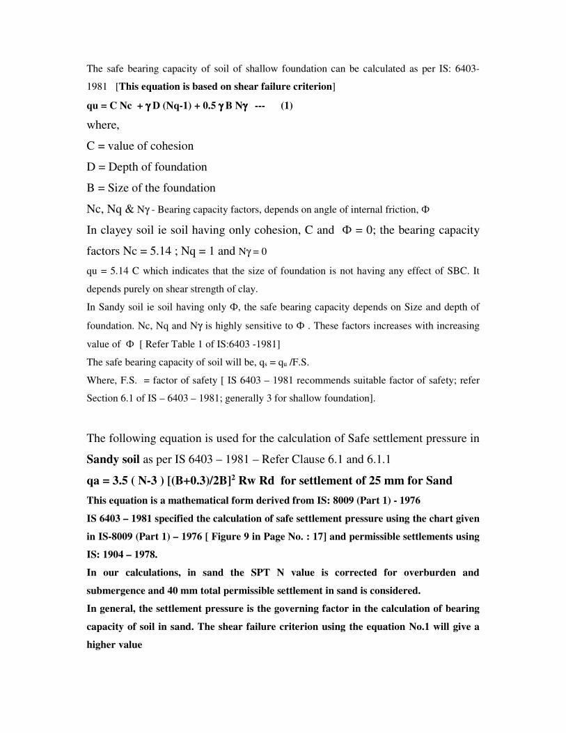
The safe bearing capacity of soil of shallow foundation can be calculated as per IS: 6403-
1981 [This equation is based on shear failure criterion]
qu = C Nc + γγγγ D (Nq-1) + 0.5 γγγγ B Nγγγγ --- (1)
where,
C = value of cohesion
D = Depth of foundation
B = Size of the foundation
Nc, Nq & Nγ - Bearing capacity factors, depends on angle of internal friction, Ф
In clayey soil ie soil having only cohesion, C and Ф = 0; the bearing capacity
factors Nc = 5.14 ; Nq = 1 and Nγ = 0
qu = 5.14 C which indicates that the size of foundation is not having any effect of SBC. It
depends purely on shear strength of clay.
In Sandy soil ie soil having only Ф, the safe bearing capacity depends on Size and depth of
foundation. Nc, Nq and Nγ is highly sensitive to Ф . These factors increases with increasing
value of Ф [ Refer Table 1 of IS:6403 -1981]
The safe bearing capacity of soil will be, qs = qu /F.S.
Where, F.S. = factor of safety [ IS 6403 – 1981 recommends suitable factor of safety; refer
Section 6.1 of IS – 6403 – 1981; generally 3 for shallow foundation].
The following equation is used for the calculation of Safe settlement pressure in
Sandy soil as per IS 6403 – 1981 – Refer Clause 6.1 and 6.1.1
qa = 3.5 ( N-3 ) [(B+0.3)/2B]2 Rw Rd for settlement of 25 mm for Sand
This equation is a mathematical form derived from IS: 8009 (Part 1) - 1976
IS 6403 – 1981 specified the calculation of safe settlement pressure using the chart given
in IS-8009 (Part 1) – 1976 [ Figure 9 in Page No. : 17] and permissible settlements using
IS: 1904 – 1978.
In our calculations, in sand the SPT N value is corrected for overburden and
submergence and 40 mm total permissible settlement in sand is considered.
In general, the settlement pressure is the governing factor in the calculation of bearing
capacity of soil in sand. The shear failure criterion using the equation No.1 will give a
higher value

The allowable bearing capacity of soil is calculated as per IS 6403 specification considering
the shear failure and settlement failure criterion using the following equations.
qu = C Nc Sc Dc + γ D Nq Sq Dq Rw2 + 0.5 γ B NγSγDγRw2 ---- (1)
qa = 35 ( N-3 ) [(B+0.3)/2B]2 Rw Rd for settlement of 25 mm for sand (2)
Qa = 1.25 N for clayey soil (3)
The bearing capacity of soil at different depth is given in Table 1, 3, 5, 7, 9, 11, 13, 15 &
17.
For Example: for Grid C – 1 Bore Hole
Depth = 1.00m to 2.00
Type of soil sample = UDS and SPT
Recorded SPT, N Value = 4/4/7 = 11 at 1.50 m level
Soil Type : Brownish plastic silty clay
Soil Classification: MH - CH
Natural moisture content = 32 %
Unit weight,γ = 2.00 t/m3
Cohesion, C = 5.00 t/m2
Angle of internal friction, φ = 0 degrees
Recorded SPT, N Value = 11
Corrected N value for overburden, saturation = 11 [ Since it is clay]
Assuming the water table may rise upto the top level.
For φ = 0 degrees, Nc = 5.14 , Nq = 1 & Nγ = 0
qu = 5.14 x 1.3 x 5.0 t/m2
= 33.41 t/m2
qs= 33.41 /3 = 11.13 t/m2
qn = qs + γ D = 11.13 + 1.5 x 1.00 = 11.13 + 1.5 = 12.63 t/m2 using shear criterion
In clay, settlement due to consolidation is to be calculated for this pressure. The
settlements should be with in the permissible limits.
For Example: for Grid C – 1 Bore Hole
Depth = 5.00m to 6.00
Type of soil sample = SPT
Recorded SPT, N Value = 7/10/11 = 21 at 5.00 m level
Soil Type : yellowish brown silty fine to medium sand

Soil Classification: SM - SP
Unit weight,γ = 1.96 t/m3
Cohesion, C = 0 t/m2
Angle of internal friction, φ = 34 degrees
Recorded SPT, N Value = 21
Corrected N value for overburden, saturation = 24
For φ = 33 degrees local shear failure is assumed
Assuming the water table may rise upto the top level.
qs > 40 t/m2
SBC calculation as per Settlement criterion:
The safe settlement pressure of Open foundation can be calculated for an allowable
settlement as per IS: 6403-1981 for shallow foundation
For N= 23 and B = 11 m
Settlement of foundation = 12 mm per 10 t/m2 [ 1.0 kg/cm2]
Settlement under submergence = 24 mm
Maximum permissible settlement = 50 mm [ from IS : 1904 - 1986 ]
Allowable bearing pressure = [ 10 x 50 / 24 ] = 20.83 t/m2
Hence an allowable bearing pressure of 20.0 t/m2 is proposed based on
settlement criterion rather than the shear criterion namely 40 t/m2
The above calculation can be made mathematically using
qa = 0.14 x S ( N-3 ) [(B+0.3)/2B]2 Rw for settlement of “S” mm
qa = 0.14 x 50 x [ 26 – 3] [(11 + 0.3)/(2 x11)]2 x 0.50
= 21.24 t/m2 say 21.00 t/m2
An allowable bearing capacity of 200 kN/m2 [ 20.0 t/m2] is proposed based
on settlement criterion at 5.00 m level for Open foundation.
Deep Foundation in the form of Bored cast in situ pile foundation is ideal for this location for
heavy loading and less number of columns. The length and size & its load carrying capacity
can be obtained from the soil properties given in Tables.
In case of pile foundation, the load carrying capacity of the pile can be calculated using
the static formula given by IS:2911(Part 1/Sec 2) - 2010 considering both friction and

bearing resistance. The allowable load is normally obtained by using an overall factor of
safety of 2.5. The load carrying of pile can also be obtained from the SPT, N values.
For the correlation of cohesion and unconfined compressive strength, static cone resistance
from N values, IS:2911- 2010 is followed.
Unconfined compressive strength = qc = N
Cohesion, Cu = qc/2
Static cone resistance = 2N
The ultimate load carrying capacity of single pile can be obtained from Static Formula as
given in IS 2911(Part 1/Sec3) – 1979 for bored piles considering Skin Friction and bearing
resistance.
For Piles in Cohesive Soil [ Clay ]
Qu = Ap . Nc . Cp + α . C . As ----- ( 1 )
Ap = Cross sectional area of the pile toe
Nc = Bearing capacity factor usually taken as 9 for deep foundation
Cp = Average cohesion at pile tip
α = reduction factor [ usually 0.3 to 1 depends on the strength of clay ]
C = Average cohesion through out the length of pile
For Piles in Cohesionless Granular Soil [ Sand ]
Qu = Ap . Pd . Nq + ∑ K. Pdi . tan δ Asi
Ap = Cross sectional area of the pile toe
Pd = effective overburden pressure at pile toe
Nq = bearing capacity factor depends upon the angle of internal friction, φ
K = coefficient of earth pressure
Pdi = effective overburden pressure for the layer concerned
δ = angle of wall friction between the soil and pile – usually taken as φ
Asi = surface area of pile stem for the layer concerned
The spacing between the centres of piles will be 2.5 – 3.0 times the pile diameter. The piles
should be connected by means of pile cap. The Construction of piles should be done as per
IS:2911-1984 specifications. DMC method is preferable for long piles
Dr N R Krishnamurthy

GEOTECHNICAL LABORATORY: CIVIL ENGINEERING DEPARTMENT V.R. SIDDHARTHA ENGINEERING COLLEGE:: VIJAYAWADA – 7
TABLE: 1 Idealized Design Soil Parameters
Project: Soil Investigation for AP Capital City Seed Area of 16 Sq. KM - The Commissioner /APCRDA/ Vijayawada
Location: A.P. Capital City Seed Area - Guntur District BORE HOLE NO.: Grid – A - 1
Andhra Pradesh (Grid – “A” Line)
Reduced level of the Bore hole = Depth of Water level: 2.60 metres Depth below
the existing
ground level
(metres)
Visual Identification of soil I.S. Soil
Classification
Natural
Moisture
Content
(%)
Dry
Unit
Weight
[KN/m3]
Recorded
SPT value
(N)
Un confined
Compressive
Strength, qc
[KN/m2]
Shear Parameters Safe bearing
Capacity [KN/m2]
Cohesion C [KN/m2]
φ (deg)
0.00-1.70 Brownish plastic silty clay MH-CH 24 16.00 UDS 84 42 0 90
1.70-3.00 Brownish clayey silty sand SC-SM 19 16.50 24 - 28 30 [email protected]
3.00-4.00 Brownish sandy silty clay MH-CH 22 16.20 UDS 174 78 4 175
4.00-5.00 Brownish sandy silty clay MH-CH 25 16.20 26 204 98 4 210
5.00-5.70 Brownish sandy silty clay MH-CH 22 16.50 UDS 224 106 8 225
5.70-8.00 Yellowish brownish silty fine
to medium sand SM-SP 15,17 16.50 35,44
[Es = 550
kg/cm2] 0 36 250
8.00-15.00 Yellowish brownish silty fine
to medium sand SM-SP 21 16.50 >50
[Es = 600
kg/cm2] 0 38 275
15.00-15.45 Yellowish brownish silty fine
to medium sand SM-SP 16 16.30 44
[Es = 500
kg/cm2] 0 34 225
qc = Unconfined compressive strength
Es = Modulus of Soil

GEOTECHNICAL LABORATORY: CIVIL ENGINEERING DEPARTMENT
V.R. SIDDHARTHA ENGINEERING COLLEGE:: VIJAYAWADA – 7
TABLE No: 2 Results of Laboratory Soil Testing
Project: Soil Investigation for AP Capital City Seed Area of 16 Sq. KM - The Commissioner /APCRDA/ Vijayawada
Location: A.P. Capital City Seed Area - Guntur District BORE HOLE NO.: Grid – A - 1
Andhra Pradesh (Grid – “A” Line)
Date Depth of GWT below GL: 2.60 metres
Depth
belo
w G
L (
m)
Type
of
Sam
ple
Vis
ual
Iden
tifi
cati
on
of
Soil
I.S
. S
oil
Cla
ssif
icati
on
Unco
nfi
ned
com
pre
ssiv
e S
tren
gth
qu [
KN
.M2]
Dry
unit
Wei
ght,
γd
[KN
.M3]
Nat
ura
l M
ois
ture
Conte
nt
(%)
Liq
uid
Lim
it (
%)
Pla
stic
Lim
it (
%)
Pla
stic
ity I
ndex
Gra
vel
Siz
e (%
)
Coar
se S
and s
ize
(%)
Med
ium
San
d S
ize
(%)
Fin
e S
and s
ize
(%)
Sli
t an
d c
lay s
ize
(%)
Rec
ord
ed S
PT
Val
ue,
(N)
Dif
fere
nti
al F
ree
swel
l
Index
(%)
Speci
fic
Gra
vit
y,
G
(1) (2) (3) (4) (5) (6) (7) (8) (9) (10) (11) (12) (13) (14) (15) (16) (17) (18)
0.00-1.00 DS Brownish plastic silty clay MH-CH 0 0 0 02 98
1.00-1.45 UDS Brownish plastic silty clay MH-CH 84 16.0 24 68 26 42 60 2.68
2.00-2.45 SPT Brownish clayey silty sand SC-SM 16.5 19 0 0 30 31 39 24 2.66
3.00-3.45 UDS Brownish sandy silty clay MH-CH 174 16.2 22 55 22 33 60 2.67
4.00-4.45 SPT Brownish sandy silty clay MH-CH 204 16.2 25 54 26 28 0 0 0 6 94 26 60
5.00-5.45 UDS Brownish sandy silty clay MH-CH 224 16.5 22 56 24 32
6.00-6.45 SPT Yellowish brown silty fine
to medium sand SM-SP 16.5 15 NP NP NP 0 0 78 20 2 35
2.65

Bore Hole No: Grid - A1 Table No. 2 (Contd...)
(1) (2) (3) (4) (5) (6) (7) (8) (9) (10) (11) (12) (13) (14) (15) (16) (17) (18)
7.00-7.45 SPT Yellowish brown silty fine
to medium sand SM-SP 16.5 17 NP NP NP 0 0 80 13 7 43
8.00-8.45 SPT Yellowish brown silty fine
to medium sand SM-SP 16.5 21 NP NP NP 0 0 72 23 5 >50
9.00-9.45 SPT Yellowish brown silty fine
to medium sand SM-SP 16.5 24 NP NP NP 0 0 80 17 3 >50
10.0-10.45 SPT Yellowish brown silty fine
to medium sand SM-SP 16.5 18 NP NP NP 0 0 70 24 6 >50
11.00-11.45 SPT Yellowish brown silty fine
to medium sand SM-SP 16.5 17 NP NP NP 0 0 76 21 3 >50
2.65
12.00-12.45 SPT Yellowish brown silty fine
to medium sand SM-SP 16.5 18 NP NP NP 0 0 78 18 4 >50
13.00-13.45 SPT Yellowish brown silty fine
to medium sand SM-SP 16.5 17 NP NP NP 0 0 75 14 11 >50
14.00-14.45 SPT Yellowish brown silty fine
to medium sand SM-SP 16.5 19 NP NP NP 0 0 80 16 4 >50
15.00-15.45 SPT Yellowish brown silty fine
to medium sand SM-SP 16.3 16 NP NP NP 0 0 79 13 8 44
DS : Distributed but representative soil sample FMC : Field Moisture Content
UDS : Undisturbed soil sample FDD : Field Dry Density
SPT : Standard penetration test sample Atterberg Limits (LL,PL,SL) on soil passing 0.425 mm sieve size
GL : Ground Level Differential free swell on soil passing 0.425 mm sieve size
GWL : Ground Water Level CR : Core Recovery Ration RQD : Rock Quality Designation

GEOTECHNICAL LABORATORY: CIVIL ENGINEERING DEPARTMENT V.R. SIDDHARTHA ENGINEERING COLLEGE:: VIJAYAWADA – 7
TABLE: 3 Idealized Design Soil Parameters
Project: Soil Investigation for AP Capital City Seed Area of 16 Sq. KM - The Commissioner /APCRDA/ Vijayawada
Location: A.P. Capital City Seed Area - Guntur District BORE HOLE NO.: Grid – A - 2
Andhra Pradesh (Grid – “A” Line)
educed level of the Bore hole = Depth of Water level: 2.20 metres
Depth below
the existing
ground level
(metres)
Visual Identification of soil I.S. Soil
Classification
Natural
Moisture
Content
(%)
Dry
Unit
Weight [KN/m3]
Recorded
SPT value
(N)
Un confined
Compressive
Strength,qc [KN/m2]
Shear Parameters Safe bearing
Capacity [KN/m2]
Cohesion C [KN/m2]
φ (deg)
0.00-2.00 Brownish plastic silty clay MH-CH 24 16.40 UDS 88 44 0 90
2.00-3.00 Brownish plastic silty clay MH-CH 20 16.50 11 - 56 0 110
3.00-5.00 Yellowish brownish silty
medium to fine sand SM-SP 23,24 16.40 25,37
[Es = 550
kg/cm2] 0 36 250
5.00-9.00 Yellowish brownish fine to
medium sand SP 14,18 16.40
34,42
43,48
[Es = 550
kg/cm2] 0 36 250
9.00-15.45 Yellowish brownish fine to
medium sand SP 19,21 16.50 >50
[Es = 600
kg/cm2] 0 38 275
qc = Unconfined compressive strength
Es = Modulus of Soil

GEOTECHNICAL LABORATORY: CIVIL ENGINEERING DEPARTMENT
V.R. SIDDHARTHA ENGINEERING COLLEGE:: VIJAYAWADA – 7
TABLE No: 4 Results of Laboratory Soil Testing
Project: Soil Investigation for AP Capital City Seed Area of 16 Sq. KM - The Commissioner /APCRDA/ Vijayawada
Location: A.P. Capital City Seed Area - Guntur District BORE HOLE NO.: Grid – A - 2
Andhra Pradesh (Grid – “A” Line)
Date Depth of GWT below GL: 2.20 metres
Depth
belo
w G
L (
m)
Type
of
Sam
ple
Vis
ual
Iden
tifi
cati
on
of
Soil
I.S
. S
oil
Cla
ssif
icat
ion
Unconfi
ned
com
pre
ssiv
e
Str
ength
qu [
KN
.M2]
Dry
unit
Wei
ght,
γd
[KN
.M3]
Nat
ura
l M
ois
ture
Conte
nt
(%)
Liq
uid
Lim
it (
%)
Pla
stic
Lim
it (
%)
Pla
stic
ity I
ndex
Gra
vel
Siz
e (%
)
Coar
se S
and s
ize
(%)
Med
ium
San
d S
ize
(%)
Fin
e S
and s
ize
(%)
Sli
t an
d c
lay s
ize
(%)
Rec
ord
ed S
PT
Val
ue,
(N
)
Dif
fere
nti
al F
ree
swel
l In
dex
(%)
Speci
fic
Gra
vit
y,
G
(1) (2) (3) (4) (5) (6) (7) (8) (9) (10) (11) (12) (13) (14) (15) (16) (17) (18)
0.00-1.00 DS Brownish plastic silty clay MH-
CH 68 28 40
1.00-1.45 UDS Brownish plastic silty clay MH-
CH 88
16.
4 24 60 26 34 0 0 0 1 99 60
2.67
2.00-2.45 SPT Brownish plastic silty clay MH-
CH
16.
5 20 59 25 34 0 0 0 3 97 11 50
3.00-3.45 SPT Yellowish brownish silty
medium to fine sand SM-SP
16.
4 23 NP NP NP 0 0 36 50 14 25
2.65
4.00-4.45 SPT Yellowish brownish silty
medium to fine sand SM-SP
16.
4 24 NP NP NP 0 0 28 70 2 37
5.00-5.45 SPT Yellowish brownish fine
to medium sand SP
16.
4 20 NP NP NP 0 0 65 33 2 34
6.00-6.45 SPT Yellowish brownish fine
to medium sand SP
16.
4 14 NP NP NP 0 0 59 33 8 42
2.65
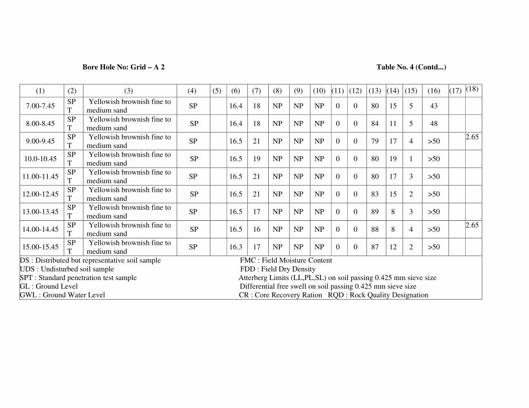
Bore Hole No: Grid – A 2 Table No. 4 (Contd...)
(1) (2) (3) (4) (5) (6) (7) (8) (9) (10) (11) (12) (13) (14) (15) (16) (17) (18)
7.00-7.45 SP
T
Yellowish brownish fine to
medium sand SP 16.4 18 NP NP NP 0 0 80 15 5 43
8.00-8.45 SP
T
Yellowish brownish fine to
medium sand SP 16.4 18 NP NP NP 0 0 84 11 5 48
9.00-9.45 SP
T
Yellowish brownish fine to
medium sand SP 16.5 21 NP NP NP 0 0 79 17 4 >50
2.65
10.0-10.45 SP
T
Yellowish brownish fine to
medium sand SP 16.5 19 NP NP NP 0 0 80 19 1 >50
11.00-11.45 SP
T
Yellowish brownish fine to
medium sand SP 16.5 21 NP NP NP 0 0 80 17 3 >50
12.00-12.45 SP
T
Yellowish brownish fine to
medium sand SP 16.5 21 NP NP NP 0 0 83 15 2 >50
13.00-13.45 SP
T
Yellowish brownish fine to
medium sand SP 16.5 17 NP NP NP 0 0 89 8 3 >50
14.00-14.45 SP
T
Yellowish brownish fine to
medium sand SP 16.5 16 NP NP NP 0 0 88 8 4 >50
2.65
15.00-15.45 SP
T
Yellowish brownish fine to
medium sand SP 16.3 17 NP NP NP 0 0 87 12 2 >50
DS : Distributed but representative soil sample FMC : Field Moisture Content
UDS : Undisturbed soil sample FDD : Field Dry Density
SPT : Standard penetration test sample Atterberg Limits (LL,PL,SL) on soil passing 0.425 mm sieve size
GL : Ground Level Differential free swell on soil passing 0.425 mm sieve size
GWL : Ground Water Level CR : Core Recovery Ration RQD : Rock Quality Designation

GEOTECHNICAL LABORATORY: CIVIL ENGINEERING DEPARTMENT V.R. SIDDHARTHA ENGINEERING COLLEGE:: VIJAYAWADA – 7
TABLE: 5 Idealized Design Soil Parameters
Project: Soil Investigation for AP Capital City Seed Area of 16 Sq. KM - The Commissioner /APCRDA/ Vijayawada
Location: A.P. Capital City Seed Area - Guntur District BORE HOLE NO.: Grid – A - 3
Andhra Pradesh (Grid – “A” Line)
Reduced level of the Bore hole = Depth of Water level: 3.80 metres
Depth below
the existing
ground level
(metres)
Visual Identification of soil I.S. Soil
Classification
Natural
Moisture
Content
(%)
Dry
Unit
Weight [KN/m3]
Recorded
SPT value
(N)
Un confined
Compressive
Strength, qc [KN/m2]
Shear Parameters Safe bearing
Capacity [KN/m2]
Cohesion C
[KN/m2] φ
(deg)
0.00-2.00 Brownish plastic silty clay MH-CH 20 17.40 UDS 128 64 0 130
2.00-3.50 Brownish plastic silty clay MH-CH 23,20 17.50 37,UDS 248 120 4 250
3.50-5.00 Yellowish brownish plastic
silty clay MH-CH 27 16.50 42 - 152 0 300
5.00-8.00 Yellowish brownish fine to
medium sand SP 19 16.40 40,47
[Es = 550
kg/cm2] 0 36 250
8.00-10.00 Yellowish brownish silty
fine to medium sand SM-SP 20 16.50 >50
[Es = 600
kg/cm2] 0 38 275
10.00-15.50 Yellowish brownish fine to
medium sand SP 18,15 16.50 >50
[Es = 600
kg/cm2] 0 38 275
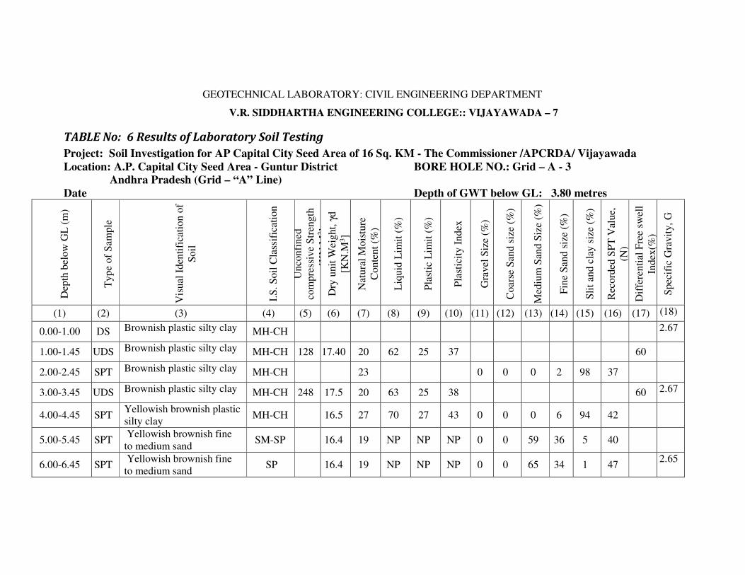
GEOTECHNICAL LABORATORY: CIVIL ENGINEERING DEPARTMENT
V.R. SIDDHARTHA ENGINEERING COLLEGE:: VIJAYAWADA – 7
TABLE No: 6 Results of Laboratory Soil Testing
Project: Soil Investigation for AP Capital City Seed Area of 16 Sq. KM - The Commissioner /APCRDA/ Vijayawada
Location: A.P. Capital City Seed Area - Guntur District BORE HOLE NO.: Grid – A - 3
Andhra Pradesh (Grid – “A” Line)
Date Depth of GWT below GL: 3.80 metres
Dep
th b
elow
GL
(m
)
Type
of
Sam
ple
Vis
ual
Iden
tifi
cati
on o
f
Soil
I.S
. S
oil
Cla
ssif
icat
ion
Unco
nfi
ned
com
pre
ssiv
e S
tren
gth
qu [
KN
.M2]
Dry
unit
Weig
ht,
γd
[KN
.M3]
Nat
ura
l M
ois
ture
Conte
nt
(%)
Liq
uid
Lim
it (
%)
Pla
stic
Lim
it (
%)
Pla
stic
ity I
ndex
Gra
vel
Siz
e (%
)
Coars
e S
and s
ize
(%)
Med
ium
San
d S
ize
(%)
Fin
e S
and s
ize
(%)
Sli
t an
d c
lay s
ize
(%)
Rec
ord
ed S
PT
Val
ue,
(N)
Dif
fere
nti
al F
ree
swel
l
Index
(%)
Spec
ific
Gra
vit
y,
G
(1) (2) (3) (4) (5) (6) (7) (8) (9) (10) (11) (12) (13) (14) (15) (16) (17) (18)
0.00-1.00 DS Brownish plastic silty clay MH-CH 2.67
1.00-1.45 UDS Brownish plastic silty clay MH-CH 128 17.40 20 62 25 37 60
2.00-2.45 SPT Brownish plastic silty clay MH-CH 23 0 0 0 2 98 37
3.00-3.45 UDS Brownish plastic silty clay MH-CH 248 17.5 20 63 25 38 60 2.67
4.00-4.45 SPT Yellowish brownish plastic
silty clay MH-CH 16.5 27 70 27 43 0 0 0 6 94 42
5.00-5.45 SPT Yellowish brownish fine
to medium sand SM-SP 16.4 19 NP NP NP 0 0 59 36 5 40
6.00-6.45 SPT Yellowish brownish fine
to medium sand SP 16.4 19 NP NP NP 0 0 65 34 1 47
2.65

Bore Hole No: Grid - A 3 Table No. 6 (Contd...)
(1) (2) (3) (4) (5) (6) (7) (8) (9) (10) (11) (12) (13) (14) (15) (16) (17) (18)
7.00-7.45 SPT Yellowish brownish fine to
medium sand SP 16.5 20 NP NP NP 0 0 69 31 0 >50
2.65
8.00-8.45 SPT Yellowish brownish silty
fine to medium sand SM-SP 16.5 19 NP NP NP 0 0 72 21 7 >50
9.00-9.45 SPT Yellowish brownish silty
fine to medium sand SM-SP 16.5 20 NP NP NP 0 0 63 29 8 >50
10.0-10.45 SPT Yellowish brownish fine to
medium sand SP 16.5 20 NP NP NP 0 0 66 29 5 >50
11.00-11.45 SPT Yellowish brownish fine to
medium sand SP 16.5 18 NP NP NP 0 0 84 14 2 >50
12.00-12.45 SPT Yellowish brownish fine to
medium sand SP 16.5 18 NP NP NP 0 0 82 14 4 >50
2.65
13.00-13.45 SPT Yellowish brownish fine to
medium sand SP 16.5 15 NP NP NP 0 0 83 13 4 >50
14.00-14.45 SPT Yellowish brownish fine to
medium sand SP 16.5 15 NP NP NP 0 0 83 15 2 >50
15.00-15.45 SPT Yellowish brownish fine to
medium sand SP 16.3 15 NP NP NP 0 0 78 14 8 >50
DS : Distributed but representative soil sample FMC : Field Moisture Content
UDS : Undisturbed soil sample FDD : Field Dry Density
SPT : Standard penetration test sample Atterberg Limits (LL,PL,SL) on soil passing 0.425 mm sieve size
GL : Ground Level Differential free swell on soil passing 0.425 mm sieve size
GWL : Ground Water Level CR : Core Recovery Ration RQD : Rock Quality Designation
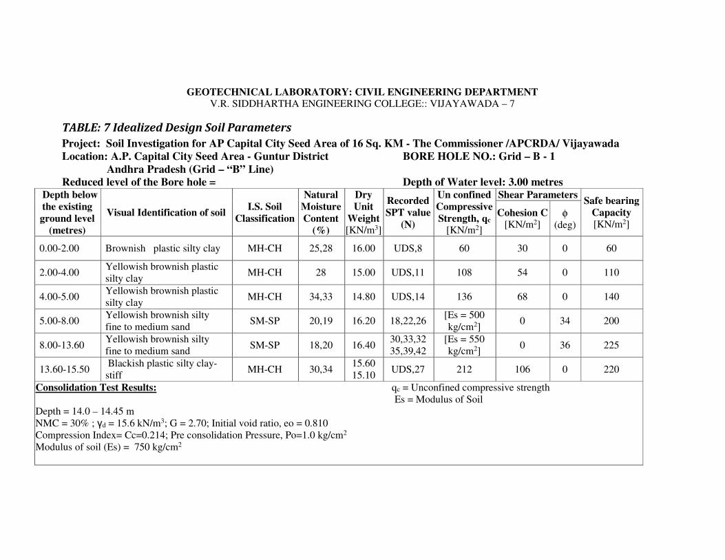
GEOTECHNICAL LABORATORY: CIVIL ENGINEERING DEPARTMENT V.R. SIDDHARTHA ENGINEERING COLLEGE:: VIJAYAWADA – 7
TABLE: 7 Idealized Design Soil Parameters
Project: Soil Investigation for AP Capital City Seed Area of 16 Sq. KM - The Commissioner /APCRDA/ Vijayawada
Location: A.P. Capital City Seed Area - Guntur District BORE HOLE NO.: Grid – B - 1
Andhra Pradesh (Grid – “B” Line)
Reduced level of the Bore hole = Depth of Water level: 3.00 metres Depth below
the existing
ground level
(metres)
Visual Identification of soil I.S. Soil
Classification
Natural
Moisture
Content
(%)
Dry
Unit
Weight [KN/m3]
Recorded
SPT value
(N)
Un confined
Compressive
Strength, qc [KN/m2]
Shear Parameters Safe bearing
Capacity
[KN/m2] Cohesion C
[KN/m2] φ
(deg)
0.00-2.00 Brownish plastic silty clay MH-CH 25,28 16.00 UDS,8 60 30 0 60
2.00-4.00 Yellowish brownish plastic
silty clay MH-CH 28 15.00 UDS,11 108 54 0 110
4.00-5.00 Yellowish brownish plastic
silty clay MH-CH 34,33 14.80 UDS,14 136 68 0 140
5.00-8.00 Yellowish brownish silty
fine to medium sand SM-SP 20,19 16.20 18,22,26
[Es = 500
kg/cm2] 0 34 200
8.00-13.60 Yellowish brownish silty
fine to medium sand SM-SP 18,20 16.40
30,33,32
35,39,42
[Es = 550
kg/cm2] 0 36 225
13.60-15.50 Blackish plastic silty clay-
stiff MH-CH 30,34
15.60
15.10 UDS,27 212 106 0 220
Consolidation Test Results: qc = Unconfined compressive strength
Es = Modulus of Soil
Depth = 14.0 – 14.45 m
NMC = 30% ; γd = 15.6 kN/m3; G = 2.70; Initial void ratio, eo = 0.810
Compression Index= Cc=0.214; Pre consolidation Pressure, Po=1.0 kg/cm2
Modulus of soil (Es) = 750 kg/cm2
GEOTECHNICAL LABORATORY: CIVIL ENGINEERING DEPARTMENT
V.R. SIDDHARTHA ENGINEERING COLLEGE:: VIJAYAWADA – 7
TABLE No: 8 Results of Laboratory Soil Testing
Project: Soil Investigation for AP Capital City Seed Area of 16 Sq. KM - The Commissioner /APCRDA/ Vijayawada
Location: A.P. Capital City Seed Area - Guntur District BORE HOLE NO.: Grid – B - 1
Andhra Pradesh (Grid – “B” Line)
Date Depth of GWT below GL: 3.00 metres
Dep
th b
elow
GL
(m
)
Type
of
Sam
ple
Vis
ual
Identi
fica
tion
of
Soil
I.S
. S
oil
Cla
ssif
icat
ion
Unco
nfi
ned
com
pre
ssiv
e S
tren
gth
qu [
KN
.M2]
Dry
unit
Wei
ght,
γd
[KN
.M3]
Nat
ura
l M
ois
ture
Conte
nt
(%)
Liq
uid
Lim
it (
%)
Pla
stic
Lim
it (
%)
Pla
stic
ity I
ndex
Gra
vel
Siz
e (%
)
Coars
e S
and s
ize
(%)
Med
ium
Sand S
ize
(%)
Fin
e S
and s
ize
(%)
Sli
t and c
lay s
ize
(%)
Rec
ord
ed S
PT
Val
ue,
(N)
Dif
fere
nti
al F
ree
swel
l
Index
(%)
Speci
fic
Gra
vit
y , G
(1) (2) (3) (4) (5) (6) (7) (8) (9) (10) (11) (12) (13) (14) (15) (16) (17) (18)
0.00-1.00 DS Brownish plastic silty clay MH-CH 0 0 0 1 99
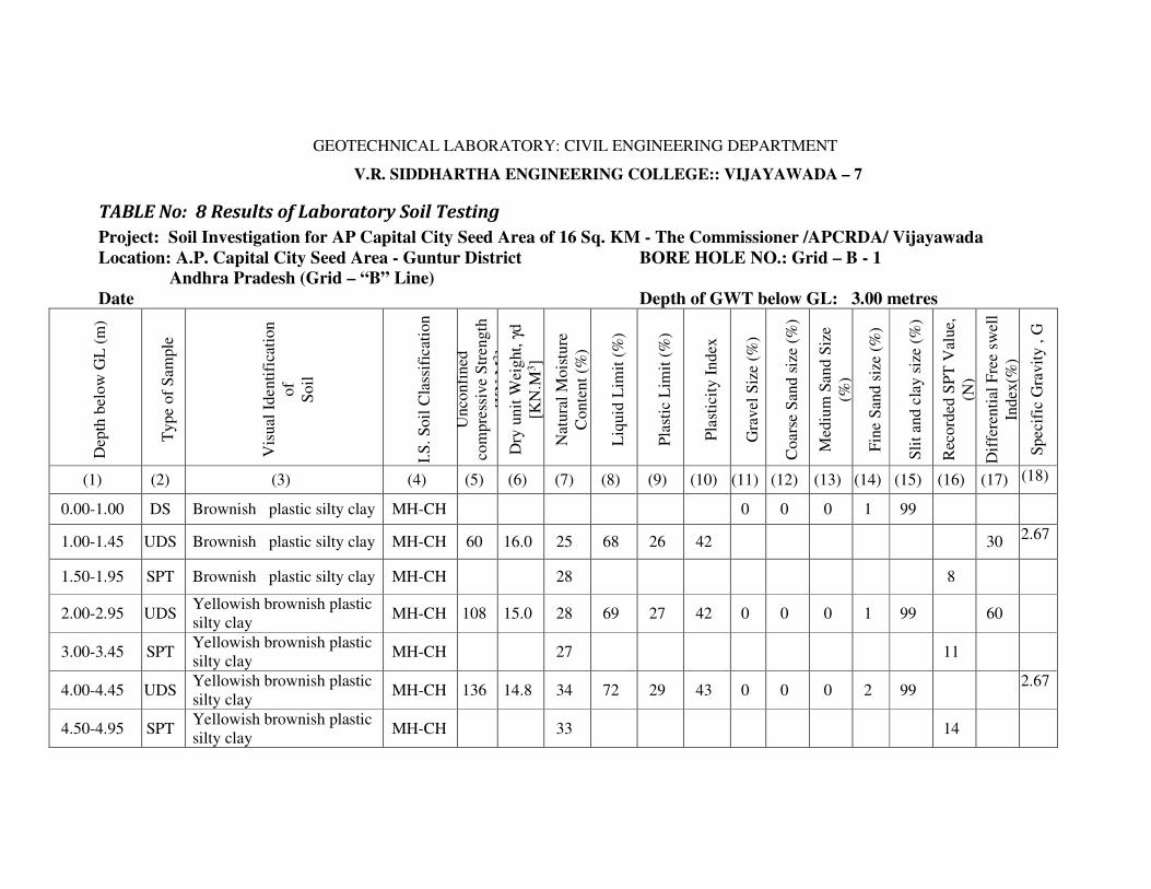
1.00-1.45 UDS Brownish plastic silty clay MH-CH 60 16.0 25 68 26 42 30 2.67
1.50-1.95 SPT Brownish plastic silty clay MH-CH 28 8
2.00-2.95 UDS Yellowish brownish plastic
silty clay MH-CH 108 15.0 28 69 27 42 0 0 0 1 99 60
3.00-3.45 SPT Yellowish brownish plastic
silty clay MH-CH 27 11
4.00-4.45 UDS Yellowish brownish plastic
silty clay MH-CH 136 14.8 34 72 29 43 0 0 0 2 99
2.67
4.50-4.95 SPT Yellowish brownish plastic
silty clay MH-CH 33 14

Bore Hole No: Grid – B1 Table No. 8 (Contd...)
(1) (2) (3) (4) (5) (6) (7) (8) (9) (10) (11) (12) (13) (14) (15) (16) (17) (18)
5.00-5.45 SPT Yellowish brownish silty
fine to medium sand SM-SP 16.2 20 NP NP NP 0 2 81 12 5 18
6.00-6.45 SPT Yellowish brownish silty
fine to medium sand SM-SP 16.2 18 NP NP NP 0 2 77 16 5 22
2.65
7.00-7.45 SPT Yellowish brownish silty
fine to medium sand SM-SP 16.2 19 NP NP NP 0 1 80 14 5 26
8.00-8.45 SPT Yellowish brownish silty
fine to medium sand SM-SP 16.4 18 NP NP NP 0 2 77 12 9 30
9.00-9.45 SPT Yellowish brownish silty
fine to medium sand SM-SP 16.4 17 NP NP NP 0 1 81 13 5 33
2.65
10.0-10.45 SPT Yellowish brownish silty
fine to medium sand SM-SP 16.4 13 NP NP NP 0 2 85 6 7 32
11.00-11.45 SPT Yellowish brownish silty
fine to medium sand SM-SP 16.4 18 NP NP NP 0 2 81 10 7 35
12.00-12.45 SPT Yellowish brownish silty
fine to medium sand SM-SP 16.4 20 NP NP NP 0 2 77 15 6 39
13.00-13.45 SPT Yellowish brownish silty
fine to medium sand SM-SP 16.4 20 NP NP NP 0 1 79 16 4 42
14.00-14.45 UDS
Blackish plastic silty clay MH-CH 212 15.6 30 86 32 54 120 2.70
15.00-15.45 SPT
Blackish plastic silty clay MH-CH 15.1 34 85 28 57 0 0 0 1 99 110
DS : Distributed but representative soil sample FMC : Field Moisture Content
UDS : Undisturbed soil sample FDD : Field Dry Density
SPT : Standard penetration test sample Atterberg Limits (LL,PL,SL) on soil passing 0.425 mm sieve size
GL : Ground Level Differential free swell on soil passing 0.425 mm sieve size
GWL : Ground Water Level CR : Core Recovery Ration RQD : Rock Quality Designation

GEOTECHNICAL LABORATORY: CIVIL ENGINEERING DEPARTMENT V.R. SIDDHARTHA ENGINEERING COLLEGE:: VIJAYAWADA – 7
TABLE: 9 Idealized Design Soil Parameters
Project: Soil Investigation for AP Capital City Seed Area of 16 Sq. KM - The Commissioner /APCRDA/ Vijayawada
Location: A.P. Capital City Seed Area - Guntur District BORE HOLE NO.: Grid – B - 2
Andhra Pradesh (Grid – “B” Line)
Reduced level of the Bore hole = Depth of Water level: 2.50 metres Depth below
the existing
ground level
(metres)
Visual Identification of soil I.S. Soil
Classification
Natural
Moisture
Content
(%)
Dry
Unit
Weight [KN/m3]
Recorded
SPT value
(N)
Un confined
Compressive
Strength, qc [KN/m2]
Shear Parameters Safe bearing
Capacity
[KN/m2] Cohesion C
[KN/m2] φ
(deg)
0.00-2.00 Brownish plastic silty clay MH-CH 30 15.0 UDS,8 68 34 0 70
2.00-3.00 Brownish plastic silty clay MH-CH 30 15.10 UDS 86 43 0 90
3.00-4.60 Brownish plastic silty clay MH-CH 30 15.20 12,UDS 128 64 0 130
4.60-8.00 Yellowish brownish silty fine
to medium sand SM-SP 17,20 16.30 22,21,24
[Es = 500
kg/cm2] 0 34 200
8.00-11.50 Yellowish brownish silty fine
to medium sand SM-SP 17 16.40
27,30
34,37
[Es = 550
kg/cm2] 0 36 225
11.50-14.00 Blackish plastic silty clay-
stiff MH-CH 24,30 15.70 UDS,16 148 74 0 150
14.00-15.50 Blackish plastic silty clay-
stiff MH-CH 31 15.30 UDS,25 240 120 0 240
Consolidation Test Results: qc = Unconfined compressive strength
Es = Modulus of Soil
Depth = 12.0 – 12.45 m
NMC = 24% ; γd = 15.7 kN/m3; G = 2.70; Initial void ratio, eo = 0.648
Compression Index= Cc=0.286; Pre consolidation Pressure, Po=0.70 kg/cm2
Modulus of soil (Es) = 750 kg/cm2

GEOTECHNICAL LABORATORY: CIVIL ENGINEERING DEPARTMENT
V.R. SIDDHARTHA ENGINEERING COLLEGE:: VIJAYAWADA – 7
TABLE No: 10 Results of Laboratory Soil Testing
Project: Soil Investigation for AP Capital City Seed Area of 16 Sq. KM - The Commissioner /APCRDA/ Vijayawada
Location: A.P. Capital City Seed Area - Guntur District BORE HOLE NO.: Grid – B - 2
Andhra Pradesh (Grid – “B” Line)
Date Depth of GWT below GL: 2.50 metres
Dep
th b
elow
GL
(m
)
Type
of
Sam
ple
Vis
ual
Identi
fica
tion
of
Soil
I.S
. S
oil
Cla
ssif
icat
ion
Unconfi
ned
com
pre
ssiv
e
Str
ength
qu [
KN
.M2]
Dry
unit
Weig
ht,
γd
[KN
.M3]
Nat
ura
l M
ois
ture
Conte
nt
(%)
Liq
uid
Lim
it (
%)
Pla
stic
Lim
it (
%)
Pla
stic
ity I
ndex
Gra
vel
Siz
e (%
)
Coars
e S
and s
ize
(%)
Med
ium
Sand S
ize
(%)
Fin
e S
and s
ize
(%)
Sli
t and c
lay s
ize
(%)
Rec
ord
ed S
PT
Val
ue,
(N
)
Dif
fere
nti
al F
ree
swel
l In
dex
(%
)
Spec
ific
Gra
vit
y , G
(1) (2) (3) (4) (5) (6) (7) (8) (9) (10) (11) (12) (13) (14) (15) (16) (17) (18)
0.00-1.00 DS Brownish plastic silty
clay MH-CH
1.00-1.45 UDS Brownish plastic silty
clay MH-CH 68 15.0 30 69 29 40 0 0 0 2 98 40
2.67
1.50-1.95 SPT Brownish plastic silty
clay MH-CH 15.0 30 8
2.50-2.95 UDS Brownish plastic silty
clay MH-CH 86 15,1 39 9 9 9 1 88 60
3.00-3.45 SPT Brownish plastic silty
clay MH-CH 15.1 30 80 29 51 12
4.00-4.45 UDS Brownish plastic silty
clay MH-CH 128 15.2 30 59 28 31 0 0 0 2 98 50
2.67
5.00-5.45 SPT Yellowish brownish silty
fine to medium sand SM-SP 16.3 17 NP NP NP 0 3 63 29 5 22

Bore Hole No: Grid, B2 Table No. 10 (Contd...)
(1) (2) (3) (4) (5) (6) (7) (8) (9) (10) (11) (12) (13) (14) (15) (16) (17) (18)
6.00-6.45 SPT Yellowish brownish silty
fine to medium sand SM-SP 16.3 20 NP NP NP 0 3 75 16 6 21
7.00-7.45 SPT Yellowish brownish silty
fine to medium sand SM-SP 16.3 21 NP NP NP 0 2 64 30 4 24
2.65
8.00-8.45 SPT Yellowish brownish silty
fine to medium sand SM-SP 16.4 17 NP NP NP 3 2 75 14 6 27
9.00-9.45 SPT Yellowish brownish silty
fine to medium sand SM-SP 16.4 17 NP NP NP 0 3 68 22 7 30
10.0-10.45 SPT Yellowish brownish silty
fine to medium sand SM-SP 16.4 16 NP NP NP 3 2 80 11 4 34
11.00-11.45 SPT Yellowish brownish silty
fine to medium sand SM-SP 16.4 15 NP NP NP 0 2 82 8 8 37
2.65
12.00-12.45 UDS
Blackish plastic silty clay MH-CH 148 15.7 24 78 30 48 2.70
13.00-13.45 SPT Blackish plastic silty clay
MH-CH 15.7 30 0 0 0 2 98 16 80
14.00-14.45 UDS Blackish plastic silty clay
MH-CH 240 15.3 31 82 30 52 2.70
15.00-15.45 SPT Blackish plastic silty clay
MH-CH 15.3 34 25
DS : Distributed but representative soil sample FMC : Field Moisture Content
UDS : Undisturbed soil sample FDD : Field Dry Density
SPT : Standard penetration test sample Atterberg Limits (LL,PL,SL) on soil passing 0.425 mm sieve size
GL : Ground Level Differential free swell on soil passing 0.425 mm sieve size
GWL : Ground Water Level CR : Core Recovery Ration RQD : Rock Quality Designation
GEOTECHNICAL LABORATORY: CIVIL ENGINEERING DEPARTMENT V.R. SIDDHARTHA ENGINEERING COLLEGE:: VIJAYAWADA – 7
TABLE: 11 Idealized Design Soil Parameters
Project: Soil Investigation for AP Capital City Seed Area of 16 Sq. KM - The Commissioner /APCRDA/ Vijayawada
Location: A.P. Capital City Seed Area - Guntur District BORE HOLE NO.: Grid – B - 3
Andhra Pradesh (Grid – “B” Line)
Reduced level of the Bore hole = Depth of Water level: 1.80 m Depth below
the existing
ground level
(metres)
Visual Identification of soil I.S. Soil
Classification
Natural
Moisture
Content
(%)
Dry
Unit
Weight [KN/m3]
Recorded
SPT value
(N)
Un confined
Compressive
Strength [KN/m2]
Shear Parameters Safe bearing
Capacity
[KN/m2] Cohesion C
[KN/m2] φ
(deg)
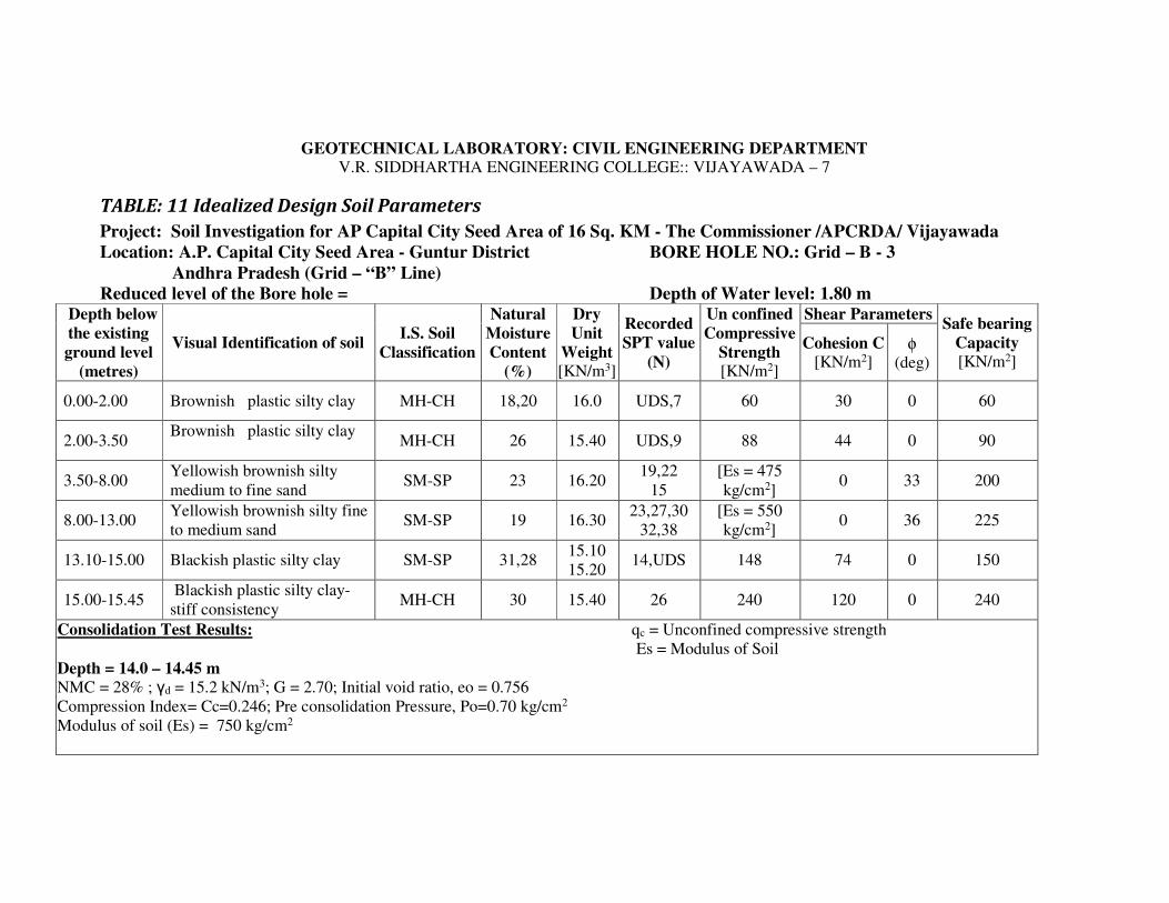
0.00-2.00 Brownish plastic silty clay MH-CH 18,20 16.0 UDS,7 60 30 0 60
2.00-3.50 Brownish plastic silty clay
MH-CH 26 15.40 UDS,9 88 44 0 90
3.50-8.00 Yellowish brownish silty
medium to fine sand SM-SP 23 16.20
19,22
15
[Es = 475
kg/cm2] 0 33 200
8.00-13.00 Yellowish brownish silty fine
to medium sand SM-SP 19 16.30
23,27,30
32,38
[Es = 550
kg/cm2] 0 36 225
13.10-15.00 Blackish plastic silty clay SM-SP 31,28 15.10
15.20 14,UDS 148 74 0 150
15.00-15.45 Blackish plastic silty clay-
stiff consistency MH-CH 30 15.40 26 240 120 0 240
Consolidation Test Results: qc = Unconfined compressive strength
Es = Modulus of Soil
Depth = 14.0 – 14.45 m
NMC = 28% ; γd = 15.2 kN/m3; G = 2.70; Initial void ratio, eo = 0.756
Compression Index= Cc=0.246; Pre consolidation Pressure, Po=0.70 kg/cm2
Modulus of soil (Es) = 750 kg/cm2

GEOTECHNICAL LABORATORY: CIVIL ENGINEERING DEPARTMENT
V.R. SIDDHARTHA ENGINEERING COLLEGE:: VIJAYAWADA – 7
TABLE No: 12 Results of Laboratory Soil Testing
Project: Soil Investigation for AP Capital City Seed Area of 16 Sq. KM - The Commissioner /APCRDA/ Vijayawada
Location: A.P. Capital City Seed Area - Guntur District BORE HOLE NO.: Grid – B - 3
Andhra Pradesh (Grid – “B” Line)
Date Depth of GWT below GL: 1.80 m
Dep
th b
elow
GL
(m)
Type
of
Sam
ple
Vis
ual
Iden
tifi
cati
on
of
Soil
I.S
. S
oil
Cla
ssif
icat
ion
Unco
nfi
ned
com
pre
ssiv
e
Str
ength
qu
Dry
unit
Wei
ght,
γd
[KN
.M3]
Natu
ral
Mois
ture
Conte
nt
(%)
Liq
uid
Lim
it (
%)
Pla
stic
Lim
it (
%)
Pla
stic
ity I
ndex
Gra
vel
Siz
e (%
)
Coars
e S
and s
ize
(%)
Med
ium
San
d S
ize
(%)
Fin
e S
and s
ize
(%)
Sli
t an
d c
lay s
ize
(%)
Rec
ord
ed S
PT
Val
ue,
(N
)
Dif
fere
nti
al F
ree
swell
Index
(%
)
Spec
ific
Gra
vit
y , G
(1) (2) (3) (4) (5) (6) (7) (8) (9) (10) (11) (12) (13) (14) (15) (16) (17) (18)
0.00-1.00 DS Brownish plastic silty
clay MH-CH
1.00-1.45 UDS Brownish plastic silty
clay MH-CH 60 16.0 18 54 26 28 0 0 0 2 98 40
2.67
1.50-1.95 SPT Brownish plastic silty
clay MH-CH 16.0 20 7
2.50-2.95 UDS Brownish plastic silty
clay MH-CH 88 15.4 26 56 26 30 40
3.00-3.45 SPT Brownish plastic silty
clay MH-CH 15.4 26 0 0 0 3 97 9
2.67
4.00-4.45 SPT Yellowish brownish silty
medium to fine sand SM-SP 16.2 23 NP NP NP 0 0 25 65 10 16
5.00-5.45 SPT Yellowish brownish silty
medium to fine sand SM-SP 16.2 22 NP NP NP 0 0 23 72 5 19
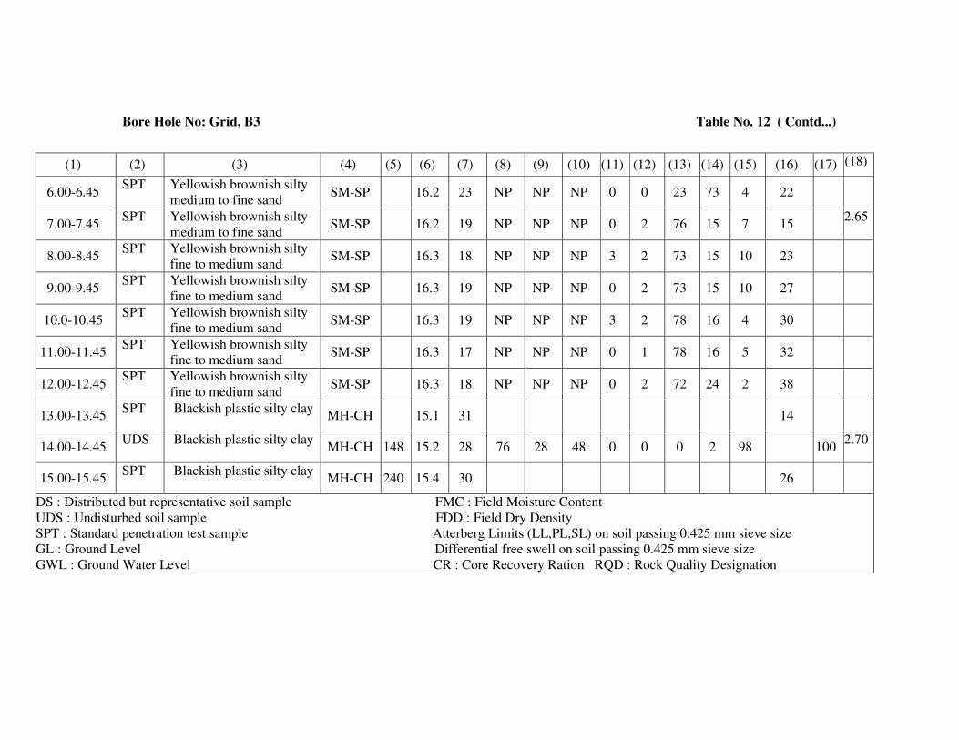
Bore Hole No: Grid, B3 Table No. 12 ( Contd...)
(1) (2) (3) (4) (5) (6) (7) (8) (9) (10) (11) (12) (13) (14) (15) (16) (17) (18)
6.00-6.45 SPT Yellowish brownish silty
medium to fine sand SM-SP 16.2 23 NP NP NP 0 0 23 73 4 22
7.00-7.45 SPT Yellowish brownish silty
medium to fine sand SM-SP 16.2 19 NP NP NP 0 2 76 15 7 15
2.65
8.00-8.45 SPT Yellowish brownish silty
fine to medium sand SM-SP 16.3 18 NP NP NP 3 2 73 15 10 23
9.00-9.45 SPT Yellowish brownish silty
fine to medium sand SM-SP 16.3 19 NP NP NP 0 2 73 15 10 27
10.0-10.45 SPT Yellowish brownish silty
fine to medium sand SM-SP 16.3 19 NP NP NP 3 2 78 16 4 30
11.00-11.45 SPT Yellowish brownish silty
fine to medium sand SM-SP 16.3 17 NP NP NP 0 1 78 16 5 32
12.00-12.45 SPT Yellowish brownish silty
fine to medium sand SM-SP 16.3 18 NP NP NP 0 2 72 24 2 38
13.00-13.45 SPT Blackish plastic silty clay
MH-CH 15.1 31 14
14.00-14.45 UDS Blackish plastic silty clay
MH-CH 148 15.2 28 76 28 48 0 0 0 2 98 100 2.70
15.00-15.45 SPT Blackish plastic silty clay
MH-CH 240 15.4 30 26
DS : Distributed but representative soil sample FMC : Field Moisture Content
UDS : Undisturbed soil sample FDD : Field Dry Density
SPT : Standard penetration test sample Atterberg Limits (LL,PL,SL) on soil passing 0.425 mm sieve size
GL : Ground Level Differential free swell on soil passing 0.425 mm sieve size
GWL : Ground Water Level CR : Core Recovery Ration RQD : Rock Quality Designation

GEOTECHNICAL LABORATORY: CIVIL ENGINEERING DEPARTMENT V.R. SIDDHARTHA ENGINEERING COLLEGE:: VIJAYAWADA – 7
TABLE: 13 Idealized Design Soil Parameters
Project: Soil Investigation for AP Capital City Seed Area of 16 Sq. KM - The Commissioner /APCRDA/ Vijayawada
Location: A.P. Capital City Seed Area - Guntur District BORE HOLE NO.: Grid – C - 1
Andhra Pradesh (Grid – “C” Line)
Reduced level of the Bore hole = Depth of Water level: 2.00 metres Depth below
the existing
ground level
(metres)
Visual Identification of soil I.S. Soil
Classification
Natural
Moisture
Content
(%)
Dry
Unit
Weight [KN/m3]
Recorded
SPT value
(N)
Un confined
Compressive
Strength, qc [KN/m2]
Shear Parameters Safe bearing
Capacity
[KN/m2] Cohesion C
[KN/m2] φ
(deg)
0.00-2.50 Brownish plastic silty clay MH-CH 25,32 16.0
15.70 UDS,11 106 50 2 110
2.50-4.00 Brownish plastic silty clay
MH-CH 34,33 15.40
15.50 UDS,13 124 62 0 125
4.00-4.90 Brownish plastic silty clay MH-CH 34 15.40 UDS,16 154 72 0 160
4.90-9.00 Yellowish brownish silty
fine to medium sand SM-SP 21 16.30
21,26
28,32
[Es = 500
kg/cm2] 0 34 200
9.00-12.00 Yellowish brownish silty
fine to medium sand SM-SP 20 16.40
38,37
42
[Es = 550
kg/cm2] 0 36 225
12.00-14.10 Yellowish brownish silty
fine to medium sand SM-SP 18 16.30 31,28
[Es = 500
kg/cm2] 0 34 200
14.10-15.50 Blackish plastic silty clay MH-CH 30 15.60 UDS,25 208 104 0 210
Consolidation Test Results: qc = Unconfined compressive strength
Es = Modulus of Soil
Depth = 14.0 – 14.45 m
NMC = 30% ; γd = 15.6 kN/m3; G = 2.70; Initial void ratio, eo = 0.810
Compression Index= Cc=0.250; Pre consolidation Pressure, Po=1.00 kg/cm2
Modulus of soil (Es) = 750 kg/cm2
GEOTECHNICAL LABORATORY: CIVIL ENGINEERING DEPARTMENT
V.R. SIDDHARTHA ENGINEERING COLLEGE:: VIJAYAWADA – 7
TABLE No: 14 Results of Laboratory Soil Testing
Project: Soil Investigation for AP Capital City Seed Area of 16 Sq. KM - The Commissioner /APCRDA/ Vijayawada
Location: A.P. Capital City Seed Area - Guntur District BORE HOLE NO.: Grid – C - 1
Andhra Pradesh (Grid – “C” Line)
Date Depth of GWT below GL: 2.00m
Depth
bel
ow
GL
(m
)
Type
of
Sam
ple
Vis
ual
Iden
tifi
cati
on
of
Soil
I.S
. S
oil
Cla
ssif
icat
ion
Unconfi
ned
com
pre
ssiv
e
Str
ength
qu [
KN
.M2]
Dry
unit
Wei
ght,
γd
[KN
.M3]
Nat
ura
l M
ois
ture
Conte
nt
(%)
Liq
uid
Lim
it (
%)
Pla
stic
Lim
it (
%)
Pla
stic
ity I
ndex
Gra
vel
Siz
e (%
)
Coar
se S
and s
ize
(%)
Med
ium
San
d S
ize
(%)
Fin
e S
and s
ize
(%)
Sli
t an
d c
lay s
ize
(%)
Rec
ord
ed S
PT
Val
ue,
(N
)
Dif
fere
nti
al F
ree
swell
Index
(%)
Speci
fic
Gra
vit
y , G
(1) (2) (3) (4) (5) (6) (7) (8) (9) (10) (11) (12) (13) (14) (15) (16) (17) (18)
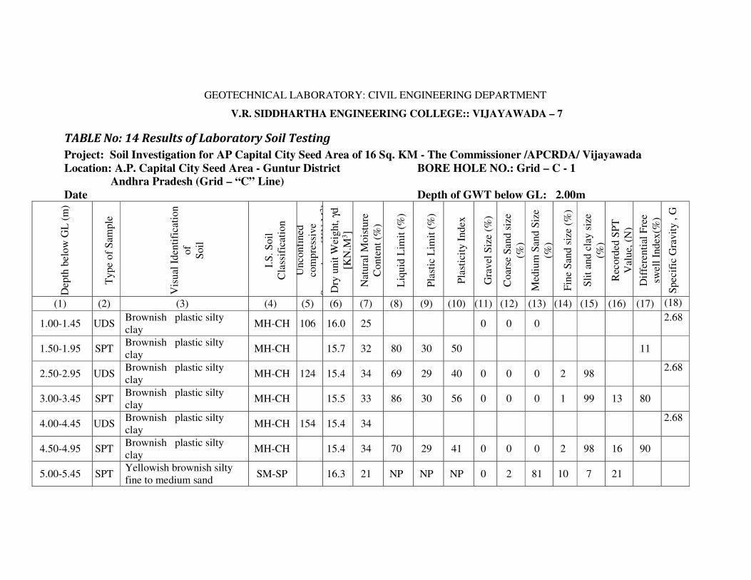
1.00-1.45 UDS Brownish plastic silty
clay MH-CH 106 16.0 25 0 0 0
2.68
1.50-1.95 SPT Brownish plastic silty
clay MH-CH 15.7 32 80 30 50 11
2.50-2.95 UDS Brownish plastic silty
clay MH-CH 124 15.4 34 69 29 40 0 0 0 2 98
2.68
3.00-3.45 SPT Brownish plastic silty
clay MH-CH 15.5 33 86 30 56 0 0 0 1 99 13 80
4.00-4.45 UDS Brownish plastic silty
clay MH-CH 154 15.4 34
2.68
4.50-4.95 SPT Brownish plastic silty
clay MH-CH 15.4 34 70 29 41 0 0 0 2 98 16 90
5.00-5.45 SPT Yellowish brownish silty
fine to medium sand SM-SP 16.3 21 NP NP NP 0 2 81 10 7 21

Bore Hole No: Grid – C, 1 Table No. 14 (Contd...)
(1) (2) (3) (4) (5) (6) (7) (8) (9) (10) (11) (12) (13) (14) (15) (16) (17) (18)
6.00-6.45 SPT Yellowish brownish silty
fine to medium sand SM-SP 16.3 19 NP NP NP 0 2 80 11 7 26
7.00-7.45 SPT Yellowish brownish silty
fine to medium sand SM-SP 16.3 17 NP NP NP 0 1 78 13 8 28
8.00-8.45 SPT Yellowish brownish silty
fine to medium sand SM-SP 16.3 15 NP NP NP 0 2 88 5 5 32
2.65
9.00-9.45 SPT Yellowish brownish silty
fine to medium sand SM-SP 16.4 18 NP NP NP 0 2 83 12 3 38
10.0-10.45 SPT Yellowish brownish silty
fine to medium sand SM-SP 16.4 19 NP NP NP 0 2 82 10 6 37
11.00-11.45 SPT Yellowish brownish silty
fine to medium sand SM-SP 16.4 19 NP NP NP 0 2 83 9 6 42
12.00-12.45 SPT Yellowish brownish silty
fine to medium sand SM-SP 16.3 20 NP NP NP 0 2 81 11 4 31
13.00-13.45 SPT Yellowish brownish silty
fine to medium sand SM-SP 16.3 18 NP NP NP 0 2 83 9 6 28
14.00-14.45 UDS Blackish plastic silty
clay-medium stiff MH-CH 208 15.6 30 74 30 44 60
15.00-15.45 SPT Blackish plastic silty
clay- medium stiff MH-CH 15.6 31 0 0 0 2 98 25
2.70
DS : Distributed but representative soil sample FMC : Field Moisture Content
UDS : Undisturbed soil sample FDD : Field Dry Density
SPT : Standard penetration test sample Atterberg Limits (LL,PL,SL) on soil passing 0.425 mm sieve size
GL : Ground Level Differential free swell on soil passing 0.425 mm sieve size
GWL : Ground Water Level CR : Core Recovery Ration RQD : Rock Quality Designation

GEOTECHNICAL LABORATORY: CIVIL ENGINEERING DEPARTMENT V.R. SIDDHARTHA ENGINEERING COLLEGE:: VIJAYAWADA – 7
TABLE: 15 Idealized Design Soil Parameters
Project: Soil Investigation for AP Capital City Seed Area of 16 Sq. KM - The Commissioner /APCRDA/ Vijayawada
Location: A.P. Capital City Seed Area - Guntur District BORE HOLE NO.: Grid – C - 2
Andhra Pradesh (Grid – “C” Line)
Reduced level of the Bore hole = Depth of Water level: 1.50m
Depth below
the existing
ground level
(metres)
Visual Identification of soil
I.S. Soil
Classificat
ion
Natural
Moisture
Content
(%)
Dry
Unit
Weight [KN/m3
]
Recorded
SPT value
(N)
Un confined
Compressive
Strength, qc
[KN/m2]
Shear
Parameters Safe bearing
Capacity [KN/m2]
Cohesion
C [KN/m2]
φ (deg)
0.00-2.50 Brownish plastic silty clay MH-CH 30,29 15.50
15.60 UDS,9 104 52 0 105
2.50-3.60 Brownish plastic silty clay
MH-CH 30,31 15.50
15.40 UDS,14 136 68 0 140
3.60-6.00 Yellowish brownish silty fine to
medium sand SM-SP 26 16.30 22,23
[Es = 500
kg/cm2] 0 34 200
6.00-10.00 Yellowish brownish fine to
medium sand SP 22 16.30
28,24
27,20
[Es = 500
kg/cm2] 0 34 200
10.00-12.00 Yellowish brownish fine to medium
sand SP 21 16.40 35,38
[Es = 550
kg/cm2] 0 36 225
12.00-14.00 Blackish brown plastic silty clay MH-CH 34 15.2 UDS,12 118 59 0 120
14.00-15.50 Blackish brown plastic silty clay MH-CH 28 15.5 UDS,22 202 101 0 200
Consolidation Test Results: qc = Unconfined compressive strength
Es = Modulus of Soil
Depth = 12.0 – 12.45 m
NMC = 34% ; γd = 15.2 kN/m3; G = 2.70; Initial void ratio, eo = 0.918
Compression Index= Cc=0.320; Pre consolidation Pressure, Po=0.50 kg/cm2
Modulus of soil (Es) = 600 kg/cm2

GEOTECHNICAL LABORATORY: CIVIL ENGINEERING DEPARTMENT
V.R. SIDDHARTHA ENGINEERING COLLEGE:: VIJAYAWADA – 7
TABLE No: 16 Results of Laboratory Soil Testing
Project: Soil Investigation for AP Capital City Seed Area of 16 Sq. KM - The Commissioner /APCRDA/ Vijayawada
Location: A.P. Capital City Seed Area - Guntur District BORE HOLE NO.: Grid – C - 2
Andhra Pradesh (Grid – “C” Line)
Date Depth of GWT below GL: 1.50 m
Depth
belo
w G
L
(m)
Type
of
Sam
ple
Vis
ual
Iden
tifi
cati
on o
f
Soil
I.S
. S
oil
Cla
ssif
icat
ion
Unconfi
ned
com
pre
ssiv
e
Str
ength
qu
Dry
unit
Weig
ht,
γd [
KN
.M3]
Nat
ura
l M
ois
ture
Conte
nt
(%)
Liq
uid
Lim
it (
%)
Pla
stic
Lim
it (
%)
Pla
stic
ity I
ndex
Gra
vel
Siz
e (%
)
Coar
se S
and s
ize
(%)
Med
ium
San
d
Siz
e (%
)
Fin
e S
and s
ize
(%)
Sli
t an
d c
lay s
ize
(%)
Rec
ord
ed S
PT
Val
ue,
(N
)
Dif
fere
nti
al F
ree
swel
l In
dex
(%)
Speci
fic
Gra
vit
y ,
G
(1) (2) (3) (4) (5) (6) (7) (8) (9) (10) (11) (12) (13) (14) (15) (16) (17) (18)
1.00-1.45 UDS Brownish plastic silty
clay MH-CH 104 15.5 30 0 0 0 1 99 60
1.50-1.95 SPT Brownish plastic silty
clay MH-CH 15.6 29 68 28 40 9
2.68
2.50-2.95 UDS Brownish plastic silty
clay MH-CH 136 15.5 30 70 29 41 60
3.00-3.45 SPT Brownish plastic silty
clay MH-CH 15.4 31 0 0 0 1 99 14
4.00-4.45 SPT Yellowish brownish silty
fine to medium sand SM-SP 16.3 26 NP NP NP 0 0 78 17 5 22
2.65
5.00-5.45 SPT Yellowish brownish silty
fine to medium sand SM-SP 16.3 24 NP NP NP 0 0 68 30 2 23
6.00-6.45 SPT Yellowish brownish fine
to medium sand SP 16.3 15 NP NP NP 0 0 91 4 5 28
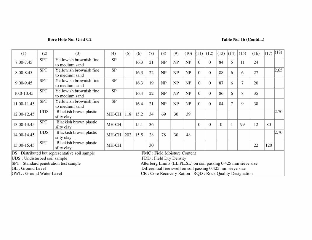
Bore Hole No: Grid C2 Table No. 16 (Contd...)
(1) (2) (3) (4) (5) (6) (7) (8) (9) (10) (11) (12) (13) (14) (15) (16) (17) (18)
7.00-7.45 SPT Yellowish brownish fine
to medium sand
SP 16.3 21 NP NP NP 0 0 84 5 11 24
8.00-8.45 SPT Yellowish brownish fine
to medium sand
SP 16.3 22 NP NP NP 0 0 88 6 6 27
2.65
9.00-9.45 SPT Yellowish brownish fine
to medium sand
SP 16.3 19 NP NP NP 0 0 87 6 7 20
10.0-10.45 SPT Yellowish brownish fine
to medium sand
SP 16.4 22 NP NP NP 0 0 86 6 8 35
11.00-11.45 SPT Yellowish brownish fine
to medium sand
SP 16.4 21 NP NP NP 0 0 84 7 9 38
12.00-12.45 UDS Blackish brown plastic
silty clay MH-CH 118 15.2 34 69 30 39
2.70
13.00-13.45 SPT Blackish brown plastic
silty clay MH-CH 15.1 36 0 0 0 1 99 12 80
14.00-14.45 UDS Blackish brown plastic
silty clay MH-CH 202 15.5 28 78 30 48
2.70
15.00-15.45 SPT Blackish brown plastic
silty clay MH-CH 30 22 120
DS : Distributed but representative soil sample FMC : Field Moisture Content
UDS : Undisturbed soil sample FDD : Field Dry Density
SPT : Standard penetration test sample Atterberg Limits (LL,PL,SL) on soil passing 0.425 mm sieve size
GL : Ground Level Differential free swell on soil passing 0.425 mm sieve size
GWL : Ground Water Level CR : Core Recovery Ration RQD : Rock Quality Designation

GEOTECHNICAL LABORATORY: CIVIL ENGINEERING DEPARTMENT V.R. SIDDHARTHA ENGINEERING COLLEGE:: VIJAYAWADA – 7
TABLE: 17 Idealized Design Soil Parameters
Project: Soil Investigation for AP Capital City Seed Area of 16 Sq. KM - The Commissioner /APCRDA/ Vijayawada
Location: A.P. Capital City Seed Area - Guntur District BORE HOLE NO.: Grid – C - 3
Andhra Pradesh (Grid – “C” Line)
Reduced level of the Bore hole = Depth of Water level: 3.00 metres Depth below
the existing
ground level
(metres)
Visual Identification of soil I.S. Soil
Classifica
tion
Natural
Moisture
Content
(%)
Dry
Unit
Weight [KN/m3]
Recorded
SPT value
(N)
Un confined
Compressive
Strength, qc [KN/m2]
Shear Parameters Safe bearing
Capacity [KN/m2]
Cohesion C [KN/m2]
φ (deg)
0.00-2.50 Brownish plastic silty clay MH-CH 32,33 15.0
14.9
UDS,7 68 34 0 75
2.50-4.00 Brownish plastic silty clay MH-CH 32 15.0 UDS,11 108 54 0 110
4.00-5.10 Brownish plastic silty clay MH-CH 30,31 15.2
15.1
UDS,14 136 68 0 140
5.10-7.00 Yellowish brownish silty fine to
medium sand
SM-SP 18 16.30 20,29 [Es = 500
kg/cm2]
0 34 200
7.00-10.70 Yellowish brownish silty fine to
medium sand
SM-SP 20 16.40 38,41
39,46
[Es = 550
kg/cm2]
0 36 225
10.70-11.90 Yellowish brownish plastic silty
clay
MH-CH 32,34 15.2
15.0
UDS,27 206 103 0 210
11.90-14.00 Blackish brown plastic silty clay MH-CH 34 14.8 UDS,23 208 104 0 210
14.00-15.50 Blackish brown plastic silty clay MH-CH 33 14.9 UDS,39 278 139 0 280
Consolidation Test Results: qc = Unconfined compressive strength
Es = Modulus of Soil
Depth = 14.0 – 14.45 m
NMC = 33% ; γd = 14.9 kN/m3; G = 2.70; Initial void ratio, eo = 0.891
Compression Index= Cc=0.220; Pre consolidation Pressure, Po=0.90 kg/cm2
Modulus of soil (Es) = 750 kg/cm2

GEOTECHNICAL LABORATORY: CIVIL ENGINEERING DEPARTMENT
V.R. SIDDHARTHA ENGINEERING COLLEGE:: VIJAYAWADA – 7
TABLE No: 18 Results of Laboratory Soil Testing
Project: Soil Investigation for AP Capital City Seed Area of 16 Sq. KM - The Commissioner /APCRDA/ Vijayawada
Location: A.P. Capital City Seed Area - Guntur District BORE HOLE NO.: Grid – C - 3
Andhra Pradesh (Grid – “C” Line)
Date Depth of GWT below GL: 3.00 metres
Dep
th b
elow
GL
(m
)
Type
of
Sam
ple
Vis
ual
Iden
tifi
cati
on o
f
Soil
I.S
. S
oil
Cla
ssif
icat
ion
Unconfi
ned
com
pre
ssiv
e
Str
ength
qu [
KN
.M2]
Dry
unit
Weig
ht,
γd
[KN
.M3]
Nat
ura
l M
ois
ture
Conte
nt
(%)
Liq
uid
Lim
it (
%)
Pla
stic
Lim
it (
%)
Pla
stic
ity I
ndex
Gra
vel
Siz
e (%
)
Coars
e S
and s
ize
(%)
Mediu
m S
and S
ize
(%)
Fin
e S
and s
ize
(%)
Sli
t an
d c
lay s
ize
(%)
Rec
ord
ed S
PT
Val
ue,
(N)
Dif
fere
nti
al F
ree
swel
l
Index
(%)
Spec
ific
Gra
vit
y , G
(1) (2) (3) (4) (5) (6) (7) (8) (9) (10) (11) (12) (13) (14) (15) (16) (17) (18)
1.00-1.45 UDS Brownish plastic silty clay MH-CH 68 15.0 32 64 28 36 2.67
1.50-1.95 SPT Brownish plastic silty clay MH-CH 14,9 33 0 0 0 1 99 7 60
2.50-2.95 UDS Brownish plastic silty clay MH-CH 108 15.0 32 68 38
3.00-3.45 SPT Brownish plastic silty clay MH-CH 15,0 32 11 2.67
4.00-4.45 UDS Brownish plastic silty clay MH-CH 136 15.2 30 70 30 40 0 0 0 2 98 60
4.50-4.95 SPT Brownish plastic silty clay MH-CH 15.1 31 14
5.00-5.45 SPT Yellowish brownish silty
fine to medium sand SM-SP 16.3 18 NP NP NP 0 0 87 8 5 20
2.66

Bore Hole No: Grid C-3 Table No. 18 (Contd...)
(1) (2) (3) (4) (5) (6) (7) (8) (9) (10) (11) (12) (13) (14) (15) (16) (17) (18)
6.00-6.45 SPT Yellowish brownish silty
fine to medium sand SM-SP 16.3 16 NP NP NP 0 0 85 8 7 29
7.00-7.45 SPT Yellowish brownish silty
fine to medium sand SM-SP 16.4 17 NP NP NP 0 0 83 11 6 38
8.00-8.45 SPT Yellowish brownish silty
fine to medium sand SM-SP 16.4 18 NP NP NP 0 0 82 10 8 41
9.00-9.45 SPT Yellowish brownish silty
fine to medium sand SM-SP 16.4 20 NP NP NP 0 0 85 9 6 39
10.0-10.45 SPT Yellowish brownish silty
fine to medium sand SM-SP 16.4 18 NP NP NP 0 0 89 8 3 46
11.00-11.45 UDS Yellowish brownish
plastic silty clay MH-CH 206 15.2 30 78 31 48
11.50-11.95 SPT Yellowish brownish
plastic silty clay MH-CH 15.0 32 0 0 0 2 98 27
12.00-12.45 UDS Blackish brown plastic
silty clay MH-CH 208 14.8 34 79 31 48
13.00-13.45 SPT Blackish brown plastic
silty clay MH-CH 34 0 0 0 1 99 23 80
14.00-14.45 UDS Blackish brown plastic
silty clay MH-CH 278 14.9 33 84 31 53
15.0-15.45 SPT Blackish brown plastic
silty clay MH-CH 33 39
DS : Distributed but representative soil sample FMC : Field Moisture Content
UDS : Undisturbed soil sample FDD : Field Dry Density
SPT : Standard penetration test sample Atterberg Limits (LL,PL,SL) on soil passing 0.425 mm sieve size
GL : Ground Level Differential free swell on soil passing 0.425 mm sieve size
GWL : Ground Water Level CR : Core Recovery Ration RQD : Rock Quality Designation

8 CONCLUSIONS
Based on the field and laboratory test results, the following recommendations are made
for the APCRDA Capital City SEED Area of 16 Sq. KM in Guntur District, Andhra
Pradesh [ [For Grid A-1,2,3; B-1,2,3 & C-1,2,3 bore holes].
• The soil Profile consists of three layers of varying thickness.
• The top layer is residual soil namely brownish plastic silty clay [MH-CH].
• The middle layer is alluvial soil namely sand [SP].
• The bottom layer is stiff silty clay [MH-CH] and over consolidated.
• The soil profile at different locations is given in Figure 1 to 9 for various bore
hole locations namely A-1, 2, 3 ; B- 1, 2, 3 and C-1, 2, 3.
• The physical properties of soil at different depth and location are given in Tables
1 to 18.
• The safe bearing capacity of soil at different depth and location is given in Table
1, 3, 5, 7, 9, 11, 13, 15 and 17.
• Suitable foundation may be selected from the soil profile and requirement.
Dr N R Krishnamurthy
Professor Professor & Head Dean/Principal

SUB SOIL PROFILES
A -4, A -5
B -4, B -5
C -4, C -5

6 SUB SOIL PROFILES
The Sub soil profile at the bore hole locations, based on the identification of soil
samples and the results of tests (both field and laboratory) are indicated in Figure: 1 -9. The
idealized design soil parameters are given in Table 1, 3, 5, 7, 9 and 11.
6.1 Bore Hole Number: Grid A- 4 Ground Water Level = 3.10 m
Depth Below
G.L.(metres)
Soil Type and Classification Recorded SPT
“N” Value
0.00 – 1.50 Brownish sandy silty clay [MH - CH] qc= 116 kN/m2
1.50 – 2.50 Brownish clayey silty sand [SC-CI] 16
2.50 – 4.00 Brownish sandy silty clay [MH - CH] 19
4.00 – 5.00 Yellowish brown silty fine sand [SM-SP] 23
5.00 – 7.00 Yellowish brown silty fine to medium sand [SM-SP] 26, 39
7.00 – 13.00 Yellowish brown fine to medium sand [SP] 35,46,48,44,50
13.00– 15.50 Yellowish brown fine to medium sand [SM-SP] 39,37,41
6.2 Bore Hole Number: Grid A- 5 Ground Water Level = 2.50 m
Depth Below
G.L.(metres)
Soil Type and Classification Recorded SPT
“N” Value
0.00 – 2.00 Brownish plastic silty clay [MH - CH] qc = 78 kN/m2
2.00 – 3.70 Brownish plastic sandy silty clay [MH-CH] qc = 88 kN/m2
3.70 – 5.00 Yellowish brown silty fine to medium sand [SM-SP] 12
5.00 – 12.00 Yellowish brown fine to medium sand [SP] 20,23,24,28,33
12.00– 15.50 Yellowish brown fine to medium sand [SP] 35,39,43,48
6.3 Bore Hole Number: Grid B- 4 Ground Water Level = 2.20 m
Depth Below
G.L.(metres)
Soil Type and Classification Recorded SPT
“N” Value
0.00 – 2.50 Brownish plastic silty clay [MH - CH] qc =78 kN/m2
2.50 – 4.00 Brownish plastic silty clay [MH - CH] 10
4.00 – 5.00 Brownish plastic silty clay [MH - CH] 9
5.00 – 11.00 Yellowish brown silty fine to medium sand [SM-SP] 19,24,26,28,
31, 27
11.00– 15.50 Yellowish brown fine to medium sand [SP] 30,37,41,38,45
6.4 Bore Hole Number: Grid B- 5 Ground Water Level = 2.00 m
Depth Below Soil Type and Classification Recorded SPT
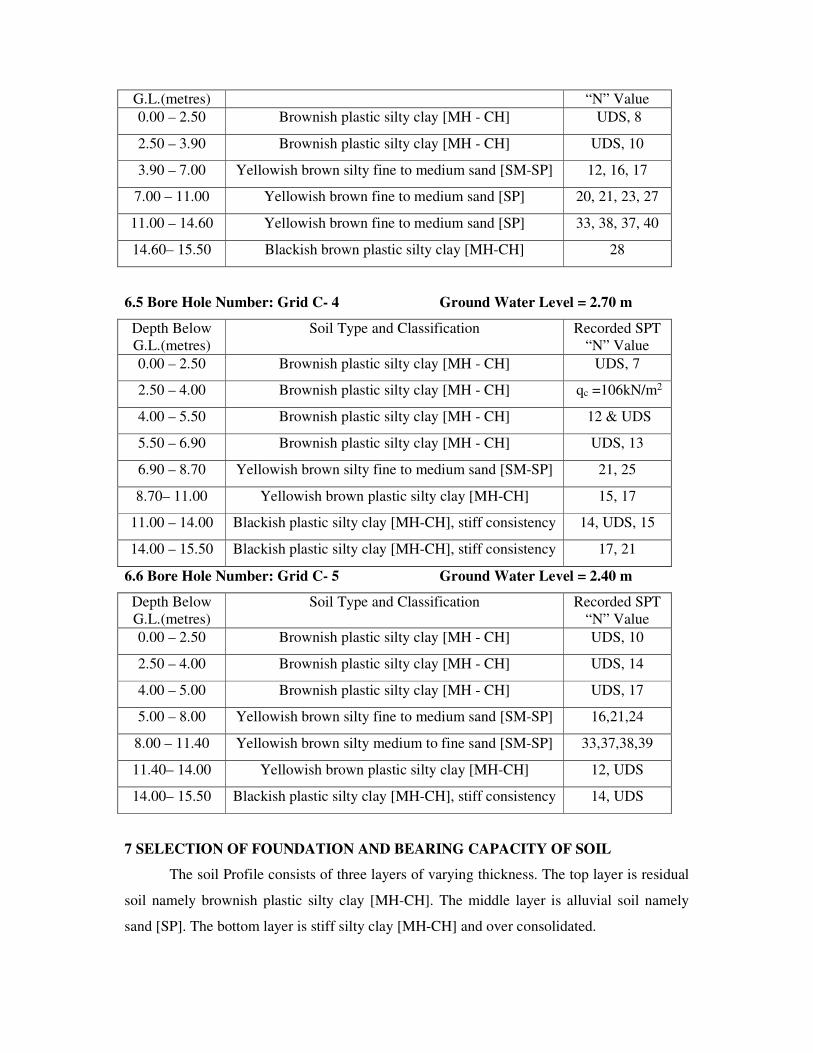
G.L.(metres) “N” Value
0.00 – 2.50 Brownish plastic silty clay [MH - CH] UDS, 8
2.50 – 3.90 Brownish plastic silty clay [MH - CH] UDS, 10
3.90 – 7.00 Yellowish brown silty fine to medium sand [SM-SP] 12, 16, 17
7.00 – 11.00 Yellowish brown fine to medium sand [SP] 20, 21, 23, 27
11.00 – 14.60 Yellowish brown fine to medium sand [SP] 33, 38, 37, 40
14.60– 15.50 Blackish brown plastic silty clay [MH-CH] 28
6.5 Bore Hole Number: Grid C- 4 Ground Water Level = 2.70 m
Depth Below
G.L.(metres)
Soil Type and Classification Recorded SPT
“N” Value
0.00 – 2.50 Brownish plastic silty clay [MH - CH] UDS, 7
2.50 – 4.00 Brownish plastic silty clay [MH - CH] qc =106kN/m2
4.00 – 5.50 Brownish plastic silty clay [MH - CH] 12 & UDS
5.50 – 6.90 Brownish plastic silty clay [MH - CH] UDS, 13
6.90 – 8.70 Yellowish brown silty fine to medium sand [SM-SP] 21, 25
8.70– 11.00 Yellowish brown plastic silty clay [MH-CH] 15, 17
11.00 – 14.00 Blackish plastic silty clay [MH-CH], stiff consistency 14, UDS, 15
14.00 – 15.50 Blackish plastic silty clay [MH-CH], stiff consistency 17, 21
6.6 Bore Hole Number: Grid C- 5 Ground Water Level = 2.40 m
Depth Below
G.L.(metres)
Soil Type and Classification Recorded SPT
“N” Value
0.00 – 2.50 Brownish plastic silty clay [MH - CH] UDS, 10
2.50 – 4.00 Brownish plastic silty clay [MH - CH] UDS, 14
4.00 – 5.00 Brownish plastic silty clay [MH - CH] UDS, 17
5.00 – 8.00 Yellowish brown silty fine to medium sand [SM-SP] 16,21,24
8.00 – 11.40 Yellowish brown silty medium to fine sand [SM-SP] 33,37,38,39
11.40– 14.00 Yellowish brown plastic silty clay [MH-CH] 12, UDS
14.00– 15.50 Blackish plastic silty clay [MH-CH], stiff consistency 14, UDS
7 SELECTION OF FOUNDATION AND BEARING CAPACITY OF SOIL
The soil Profile consists of three layers of varying thickness. The top layer is residual
soil namely brownish plastic silty clay [MH-CH]. The middle layer is alluvial soil namely
sand [SP]. The bottom layer is stiff silty clay [MH-CH] and over consolidated.

Since the proposed structures are framed structure and the top soil is silty clay
followed by sand/ silty clay, Open foundation in the form of Raft foundation/Isolated footing
and deep foundation in the form of Bored Cast in – situ pile foundation are suitable. Pile
supported raft foundation is also suitable.
The size and depth of foundation can be decided based on loading and soil
characteristics.
The depth of foundation should satisfy the following requirements.
It should rests on sound strata of adequate bearing capacity and safe from settlement
considerations also.
It should have adequate embedded length so as to resist the overturning moments due
to horizontal forces and scour.
The following points/definitions should be studied while arriving the bearing capacity of soil.
Any foundation should satisfied the two important criterion namely there should not be a
shear failure and the settlements should be within permissible limits.
The following Indian Standard Code of Practices used while calculating the bearing capacity
of soil
IS: 6403 – 1981 : Code of Practice For Determination of Bearing capacity of shallow
foundation.
IS: 1904 – 1986 : Code of Practice For Design and Construction of Foundations in Soils :
General Requirements
IS: 8009(Part 1) -1976 : Code of Practice For Calculation of Settlements of Foundations
IS: 2131: 1981 – Code of Practice – Method of Standard Penetration Test for Soils
Safe Bearing Capacity: Maximum intensity of loading that the foundation will safely carry
without the risk of shear failure of the soil irrespective of any settlement that may occur
Safe Bearing Pressure Or Net Pressure for Specified Settlement: The intensity of loading
that will cause a permissible settlement or specified settlement of the structure.
Allowable Bearing Capacity: The net intensity of loading which the foundation will carry
without undergoing settlement in excess of the permissible value for the structure under
consideration but not exceeding the net Safe Bearing capacity.
The safe bearing capacity of soil of shallow foundation can be calculated as per IS: 6403-
1981 [This equation is based on shear failure criterion]
qu = C Nc + γγγγ D (Nq-1) + 0.5 γγγγ B Nγγγγ --- (1)
where,
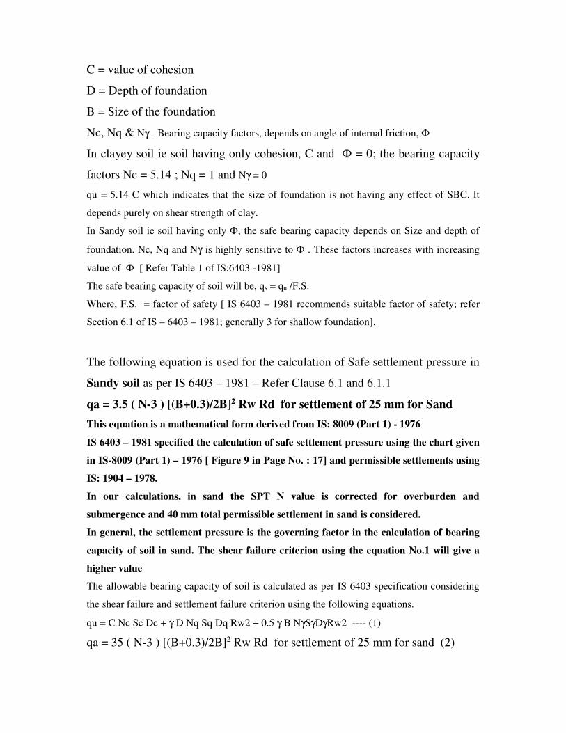
C = value of cohesion
D = Depth of foundation
B = Size of the foundation
Nc, Nq & Nγ - Bearing capacity factors, depends on angle of internal friction, Ф
In clayey soil ie soil having only cohesion, C and Ф = 0; the bearing capacity
factors Nc = 5.14 ; Nq = 1 and Nγ = 0
qu = 5.14 C which indicates that the size of foundation is not having any effect of SBC. It
depends purely on shear strength of clay.
In Sandy soil ie soil having only Ф, the safe bearing capacity depends on Size and depth of
foundation. Nc, Nq and Nγ is highly sensitive to Ф . These factors increases with increasing
value of Ф [ Refer Table 1 of IS:6403 -1981]
The safe bearing capacity of soil will be, qs = qu /F.S.
Where, F.S. = factor of safety [ IS 6403 – 1981 recommends suitable factor of safety; refer
Section 6.1 of IS – 6403 – 1981; generally 3 for shallow foundation].
The following equation is used for the calculation of Safe settlement pressure in
Sandy soil as per IS 6403 – 1981 – Refer Clause 6.1 and 6.1.1
qa = 3.5 ( N-3 ) [(B+0.3)/2B]2 Rw Rd for settlement of 25 mm for Sand
This equation is a mathematical form derived from IS: 8009 (Part 1) - 1976
IS 6403 – 1981 specified the calculation of safe settlement pressure using the chart given
in IS-8009 (Part 1) – 1976 [ Figure 9 in Page No. : 17] and permissible settlements using
IS: 1904 – 1978.
In our calculations, in sand the SPT N value is corrected for overburden and
submergence and 40 mm total permissible settlement in sand is considered.
In general, the settlement pressure is the governing factor in the calculation of bearing
capacity of soil in sand. The shear failure criterion using the equation No.1 will give a
higher value
The allowable bearing capacity of soil is calculated as per IS 6403 specification considering
the shear failure and settlement failure criterion using the following equations.
qu = C Nc Sc Dc + γ D Nq Sq Dq Rw2 + 0.5 γ B NγSγDγRw2 ---- (1)
qa = 35 ( N-3 ) [(B+0.3)/2B]2 Rw Rd for settlement of 25 mm for sand (2)

Qa = 1.25 N for clayey soil (3)
The bearing capacity of soil at different depth is given in Table 1, 3, 5, 7, 9 & 11.
For Example: for Grid C – 1 Bore Hole
Depth = 1.00m to 2.00
Type of soil sample = UDS and SPT
Recorded SPT, N Value = 3/5/5 = 10 at 1.50 m level
Soil Type : Brownish plastic silty clay
Soil Classification: MH - CH
Natural moisture content = 25 %
Unit weight,γ = 2.00 t/m3
Cohesion, C = 5.30 t/m2
Angle of internal friction, φ = 0 degrees
Recorded SPT, N Value = 10
Corrected N value for overburden, saturation = 10 [ Since it is clay]
Assuming the water table may rise upto the top level.
For φ = 0 degrees, Nc = 5.14 , Nq = 1 & Nγ = 0
qu = 5.14 x 1.3 x 5.3 t/m2
= 35.41 t/m2
qs= 35.41 /3 = 11.80 t/m2
qn = qs + γ D = 11.80 + 1.5 x 1.00 = 11.80 + 1.5 = 13.30 t/m2 using shear criterion
In clay, settlement due to consolidation is to be calculated for this pressure. The
settlements should be with in the permissible limits.
For Example: for Grid C – 1 Bore Hole
Depth = 7.00m to 8.70
Type of soil sample = SPT
Recorded SPT, N Value = 7/10/11 = 21 at 5.00 m level
Soil Type : yellowish brown silty fine to medium sand
Soil Classification: SM - SP
Unit weight,γ = 1.96 t/m3
Cohesion, C = 0 t/m2
Angle of internal friction, φ = 34 degrees
Recorded SPT, N Value = 21

Corrected N value for overburden, saturation = 23
For φ = 34 degrees local shear failure is assumed
Assuming the water table may rise upto the top level.
qs > 40 t/m2
SBC calculation as per Settlement criterion:
The safe settlement pressure of Open foundation can be calculated for an allowable
settlement as per IS: 6403-1981 for shallow foundation
For N= 23 and B = 3 m
Settlement of foundation = 15 mm per 10 t/m2 [ 1.0 kg/cm2]
Settlement under submergence = 30 mm
Maximum permissible settlement = 50 mm [ from IS : 1904 - 1986 ]
Allowable bearing pressure = [ 10 x 50 / 30 ] = 16.67 t/m2
Settlement of foundation = 12 mm per 10 t/m2 [ 1.0 kg/cm2]
Settlement under submergence = 24 mm
Maximum permissible settlement = 50 mm [ from IS : 1904 - 1986 ]
Allowable bearing pressure = [ 10 x 50 / 24 ] = 20.83 t/m2
Hence an allowable bearing pressure of 20.0 t/m2 is proposed based on
settlement criterion rather than the shear criterion namely 40 t/m2
The above calculation can be made mathematically using
qa = 0.14 x S ( N-3 ) [(B+0.3)/2B]2 Rw for settlement of “S” mm
qa = 0.14 x 50 x [ 23 – 3] [(3 + 0.3)/(2 x3)]2 x 0.50
= 21.18 t/m2 say 21.00 t/m2
An allowable bearing capacity of 200 kN/m2 [ 20.0 t/m2] is proposed based
on settlement criterion at 6.90 m level for Open foundation.
Deep Foundation in the form of Bored cast in situ pile foundation is ideal for this location for
heavy loading and less number of columns. The length and size & its load carrying capacity
can be obtained from the soil properties given in Tables.
In case of pile foundation, the load carrying capacity of the pile can be calculated using
the static formula given by IS:2911(Part 1/Sec 2) - 2010 considering both friction and
bearing resistance. The allowable load is normally obtained by using an overall factor of
safety of 2.5. The load carrying of pile can also be obtained from the SPT, N values.
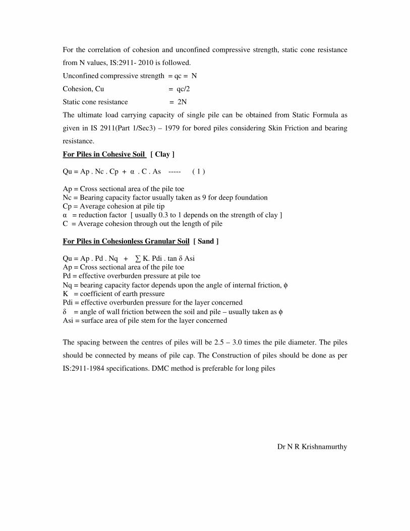
For the correlation of cohesion and unconfined compressive strength, static cone resistance
from N values, IS:2911- 2010 is followed.
Unconfined compressive strength = qc = N
Cohesion, Cu = qc/2
Static cone resistance = 2N
The ultimate load carrying capacity of single pile can be obtained from Static Formula as
given in IS 2911(Part 1/Sec3) – 1979 for bored piles considering Skin Friction and bearing
resistance.
For Piles in Cohesive Soil [ Clay ]
Qu = Ap . Nc . Cp + α . C . As ----- ( 1 )
Ap = Cross sectional area of the pile toe
Nc = Bearing capacity factor usually taken as 9 for deep foundation
Cp = Average cohesion at pile tip
α = reduction factor [ usually 0.3 to 1 depends on the strength of clay ]
C = Average cohesion through out the length of pile
For Piles in Cohesionless Granular Soil [ Sand ]
Qu = Ap . Pd . Nq + ∑ K. Pdi . tan δ Asi
Ap = Cross sectional area of the pile toe
Pd = effective overburden pressure at pile toe
Nq = bearing capacity factor depends upon the angle of internal friction, φ
K = coefficient of earth pressure
Pdi = effective overburden pressure for the layer concerned
δ = angle of wall friction between the soil and pile – usually taken as φ
Asi = surface area of pile stem for the layer concerned
The spacing between the centres of piles will be 2.5 – 3.0 times the pile diameter. The piles
should be connected by means of pile cap. The Construction of piles should be done as per
IS:2911-1984 specifications. DMC method is preferable for long piles
Dr N R Krishnamurthy
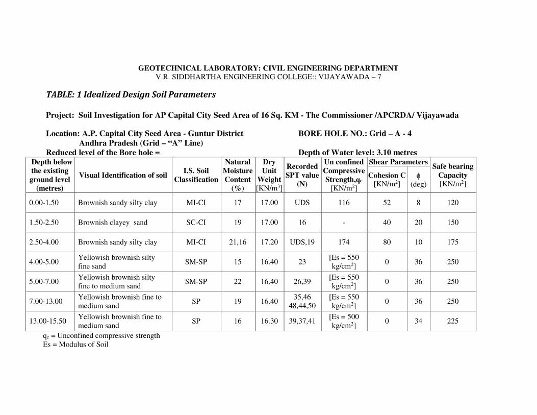
GEOTECHNICAL LABORATORY: CIVIL ENGINEERING DEPARTMENT V.R. SIDDHARTHA ENGINEERING COLLEGE:: VIJAYAWADA – 7
TABLE: 1 Idealized Design Soil Parameters
Project: Soil Investigation for AP Capital City Seed Area of 16 Sq. KM - The Commissioner /APCRDA/ Vijayawada
Location: A.P. Capital City Seed Area - Guntur District BORE HOLE NO.: Grid – A - 4
Andhra Pradesh (Grid – “A” Line)
Reduced level of the Bore hole = Depth of Water level: 3.10 metres Depth below
the existing
ground level
(metres)
Visual Identification of soil I.S. Soil
Classification
Natural
Moisture
Content
(%)
Dry
Unit
Weight
[KN/m3]
Recorded
SPT value
(N)
Un confined
Compressive
Strength,qc
[KN/m2]
Shear Parameters Safe bearing
Capacity [KN/m2]
Cohesion C [KN/m2]
φ (deg)
0.00-1.50 Brownish sandy silty clay MI-CI 17 17.00 UDS 116 52 8 120
1.50-2.50 Brownish clayey sand SC-CI 19 17.00 16 - 40 20 150
2.50-4.00 Brownish sandy silty clay MI-CI 21,16 17.20 UDS,19 174 80 10 175
4.00-5.00 Yellowish brownish silty
fine sand SM-SP 15 16.40 23
[Es = 550
kg/cm2] 0 36 250
5.00-7.00 Yellowish brownish silty
fine to medium sand SM-SP 22 16.40 26,39
[Es = 550
kg/cm2] 0 36 250
7.00-13.00 Yellowish brownish fine to
medium sand SP 19 16.40
35,46
48,44,50
[Es = 550
kg/cm2] 0 36 250
13.00-15.50 Yellowish brownish fine to
medium sand SP 16 16.30 39,37,41
[Es = 500
kg/cm2] 0 34 225
qc = Unconfined compressive strength
Es = Modulus of Soil

GEOTECHNICAL LABORATORY: CIVIL ENGINEERING DEPARTMENT
V.R. SIDDHARTHA ENGINEERING COLLEGE:: VIJAYAWADA – 7
TABLE No: 2 Results of Laboratory Soil Testing
Project: Soil Investigation for AP Capital City Seed Area of 16 Sq. KM - The Commissioner /APCRDA/ Vijayawada
Location: A.P. Capital City Seed Area - Guntur District BORE HOLE NO.: Grid – A - 4
Andhra Pradesh (Grid – “A” Line)
Date Depth of GWT below GL: 3.10 metres
Dep
th b
elow
GL
(m
)
Type
of
Sam
ple
Vis
ual
Identi
fica
tion o
f
Soil
I.S
. S
oil
Cla
ssif
icat
ion
Unconfi
ned
com
pre
ssiv
e
Str
ength
qu [
KN
.M2]
Dry
unit
Weig
ht,
γd
[KN
.M3]
Nat
ura
l M
ois
ture
Conte
nt
(%)
Liq
uid
Lim
it (
%)
Pla
stic
Lim
it (
%)
Pla
stic
ity I
ndex
Gra
vel
Siz
e (%
)
Coars
e S
and s
ize
(%)
Mediu
m S
and S
ize
(%)
Fin
e S
and s
ize
(%)
Sli
t an
d c
lay s
ize
(%)
Rec
ord
ed S
PT
Val
ue,
(N
)
Dif
fere
nti
al F
ree
swel
l
Index
(%)
Spec
ific
Gra
vit
y, G
(1) (2) (3) (4) (5) (6) (7) (8) (9) (10) (11) (12) (13) (14) (15) (16) (17) (18)
0.00-1.00 DS Brownish sandy silty clay MI-CI
1.00-1.45 UDS Brownish sandy silty clay MI-CI 116 17.0 17 49 26 23 0 0 18 9 73 40 2.67
1.50-1.95 SPT Brownish sandy
clay/clayey sand SC-CI 17.0 19 0 0 10 44 46 16
2.66
2.00-2.95 UDS Brownish sandy silty clay MI-CI 174 17.2 21 50 27 23 0 0 10 9 81 2.67
3.00-3.45 SPT Brownish sandy clay MI-CI 17.3 16 0 0 8 38 54 19
4.00-4.45 SPT Yellowish brownish silty
fine sand SM-SP 16.4 15 NP NP NP 0 0 11 60 29 23
2.65
5.00-5.45 SPT Yellowish brownish silty
fine to medium sand SM-SP 16.4 22 NP NP NP 0 0 49 35 16 26
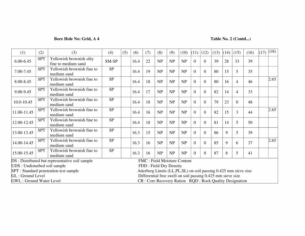
Bore Hole No: Grid, A 4 Table No. 2 (Contd...)
(1) (2) (3) (4) (5) (6) (7) (8) (9) (10) (11) (12) (13) (14) (15) (16) (17) (18)
6.00-6.45 SPT Yellowish brownish silty
fine to medium sand SM-SP 16.4 22 NP NP NP 0 0 39 28 33 39
7.00-7.45 SPT Yellowish brownish fine to
medium sand
SP 16.4 19 NP NP NP 0 0 80 15 5 35
8.00-8.45 SPT Yellowish brownish fine to
medium sand
SP 16.4 18 NP NP NP 0 0 80 16 4 46
2.65
9.00-9.45 SPT Yellowish brownish fine to
medium sand
SP 16.4 17 NP NP NP 0 0 82 14 4 33
10.0-10.45 SPT Yellowish brownish fine to
medium sand
SP 16.4 18 NP NP NP 0 0 79 23 0 48
11.00-11.45 SPT Yellowish brownish fine to
medium sand
SP 16.4 16 NP NP NP 0 0 82 15 3 44
2.65
12.00-12.45 SPT Yellowish brownish fine to
medium sand
SP 16.4 18 NP NP NP 0 0 81 14 5 50
13.00-13.45 SPT Yellowish brownish fine to
medium sand
SP 16.3 15 NP NP NP 0 0 86 9 5 39
14.00-14.45 SPT Yellowish brownish fine to
medium sand
SP 16.3 16 NP NP NP 0 0 85 9 6 37
2.65
15.00-15.45 SPT Yellowish brownish fine to
medium sand
SP 16.3 16 NP NP NP 0 0 87 8 5 41
DS : Distributed but representative soil sample FMC : Field Moisture Content
UDS : Undisturbed soil sample FDD : Field Dry Density
SPT : Standard penetration test sample Atterberg Limits (LL,PL,SL) on soil passing 0.425 mm sieve size
GL : Ground Level Differential free swell on soil passing 0.425 mm sieve size
GWL : Ground Water Level CR : Core Recovery Ration RQD : Rock Quality Designation
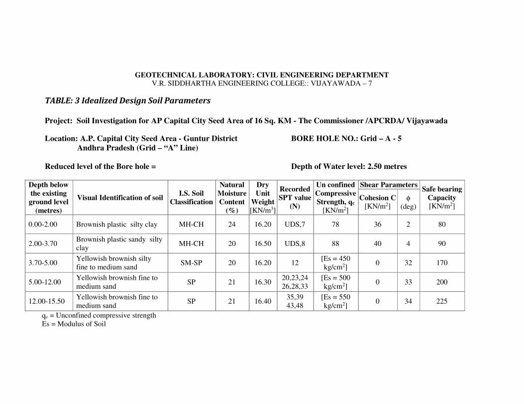
GEOTECHNICAL LABORATORY: CIVIL ENGINEERING DEPARTMENT V.R. SIDDHARTHA ENGINEERING COLLEGE:: VIJAYAWADA – 7
TABLE: 3 Idealized Design Soil Parameters
Project: Soil Investigation for AP Capital City Seed Area of 16 Sq. KM - The Commissioner /APCRDA/ Vijayawada
Location: A.P. Capital City Seed Area - Guntur District BORE HOLE NO.: Grid – A - 5
Andhra Pradesh (Grid – “A” Line)
Reduced level of the Bore hole = Depth of Water level: 2.50 metres
Depth below
the existing
ground level
(metres)
Visual Identification of soil I.S. Soil
Classification
Natural
Moisture
Content
(%)
Dry
Unit
Weight
[KN/m3]
Recorded
SPT value
(N)
Un confined
Compressive
Strength, qc
[KN/m2]
Shear Parameters Safe bearing
Capacity [KN/m2]
Cohesion C [KN/m2]
φ (deg)
0.00-2.00 Brownish plastic silty clay MH-CH 24 16.20 UDS,7 78 36 2 80
2.00-3.70 Brownish plastic sandy silty
clay MH-CH 20 16.50 UDS,8 88 40 4 90
3.70-5.00 Yellowish brownish silty
fine to medium sand SM-SP 20 16.20 12
[Es = 450
kg/cm2] 0 32 170
5.00-12.00 Yellowish brownish fine to
medium sand SP 21 16.30
20,23,24
26,28,33
[Es = 500
kg/cm2] 0 33 200
12.00-15.50 Yellowish brownish fine to
medium sand SP 21 16.40
35,39
43,48
[Es = 550
kg/cm2] 0 34 225
qc = Unconfined compressive strength
Es = Modulus of Soil

GEOTECHNICAL LABORATORY: CIVIL ENGINEERING DEPARTMENT
V.R. SIDDHARTHA ENGINEERING COLLEGE:: VIJAYAWADA – 7
TABLE No: 4 Results of Laboratory Soil Testing
Project: Soil Investigation for AP Capital City Seed Area of 16 Sq. KM - The Commissioner /APCRDA/ Vijayawada
Location: A.P. Capital City Seed Area - Guntur District BORE HOLE NO.: Grid – A - 5
Andhra Pradesh (Grid – “A” Line)
Date Depth of GWT below GL: 2.50 metres
Dep
th b
elow
GL
(m
)
Type
of
Sam
ple
Vis
ual
Iden
tifi
cati
on o
f
Soil
I.S
. S
oil
Cla
ssif
icat
ion
Unco
nfi
ned
com
pre
ssiv
e S
tren
gth
qu
[KN
.M2]
Dry
unit
Wei
ght,
γd
[KN
.M3]
Natu
ral
Mois
ture
Conte
nt
(%)
Liq
uid
Lim
it (
%)
Pla
stic
Lim
it (
%)
Pla
stic
ity I
ndex
Gra
vel
Siz
e (%
)
Coar
se S
and s
ize
(%)
Med
ium
San
d S
ize
(%)
Fin
e S
and s
ize
(%)
Sli
t an
d c
lay s
ize
(%)
Rec
ord
ed S
PT
Valu
e,
(N)
Dif
fere
nti
al F
ree
swel
l
Index
(%)
Spec
ific
Gra
vit
y,
G
(1) (2) (3) (4) (5) (6) (7) (8) (9) (10) (11) (12) (13) (14) (15) (16) (17)
0.00-1.00 DS Brownish plastic silty clay MH-CH
1.00-1.45 UDS Brownish plastic silty clay MH-CH 78 16.2 24 69 26 43 0 0 0 1 99 60 2.68
1.50-1.95 SPT Brownish plastic silty clay MH-CH 24 7
2.00-2.95 UDS Brownish sandy silty clay MH-CH 88 16.5 20 0 0 15 13 72 2.67
3.00-3.45 SPT Brownish sandy silty clay MH-CH 16.1 22 64 27 37 8 80
4.00-4.45 SPT Yellowish brownish silty
fine to medium sand
SM-SP 16.2 20 NP NP NP 0 0 83 14 13 12
5.00-5.45 SPT Yellowish brownish fine
to medium sand
SP 16.3 17 NP NP NP 0 0 77 20 3 20 2.65

Bore Hole No: Grid, A-5 Table No. 4 (Contd...)
(1) (2) (3) (4) (5) (6) (7) (8) (9) (10) (11) (12) (13) (14) (15) (16) (17) (18)
6.00-6.45 SPT Yellowish brownish fine to
medium sand SP 16.3 22 NP NP NP 0 0 74 23 3 23
2.65
7.00-7.45 SPT Yellowish brownish fine to
medium sand
SP 16.3 20 NP NP NP 0 0 75 20 5 24
8.00-8.45 SPT Yellowish brownish fine to
medium sand
SP 16.3 20 NP NP NP 0 0 76 18 6 26
9.00-9.45 SPT Yellowish brownish fine to
medium sand
SP 16.3 18 NP NP NP 0 0 78 19 3 28
10.0-10.45 SPT Yellowish brownish fine to
medium sand
SP 16.3 21 NP NP NP 0 0 68 26 6 32
11.00-11.45 SPT Yellowish brownish fine to
medium sand
SP 16.3 20 NP NP NP 0 0 77 19 4 33
12.00-12.45 SPT Yellowish brownish fine to
medium sand
SP 16.4 20 NP NP NP 0 0 71 19 10 35
2.65
13.00-13.45 SPT Yellowish brownish fine to
medium sand
SP
16.4 18 NP NP NP 0 0 75 20 5 39
14.00-14.45 SPT Yellowish brownish fine to
medium sand
SP
16.4 21 NP NP NP 0 0 64 25 11 43
15.00-15.45 SPT Yellowish brownish fine to
medium sand
SP
16.4 20 NP NP NP 0 0 76 19 5 48
DS : Distributed but representative soil sample FMC : Field Moisture Content
UDS : Undisturbed soil sample FDD : Field Dry Density
SPT : Standard penetration test sample Atterberg Limits (LL,PL,SL) on soil passing 0.425 mm sieve size
GL : Ground Level Differential free swell on soil passing 0.425 mm sieve size
GWL : Ground Water Level CR : Core Recovery Ration RQD : Rock Quality Designation

GEOTECHNICAL LABORATORY: CIVIL ENGINEERING DEPARTMENT V.R. SIDDHARTHA ENGINEERING COLLEGE:: VIJAYAWADA – 7
TABLE: 5 Idealized Design Soil Parameters
Project: Soil Investigation for AP Capital City Seed Area of 16 Sq. KM - The Commissioner /APCRDA/ Vijayawada
Location: A.P. Capital City Seed Area - Guntur District BORE HOLE NO.: Grid – B - 4
Andhra Pradesh (Grid – “B” Line)
Reduced level of the Bore hole = Depth of Water level: 2.20 metres
Depth below
the existing
ground level
(metres)
Visual Identification of soil I.S. Soil
Classification
Natural
Moisture
Content
(%)
Dry
Unit
Weight [KN/m3]
Recorded
SPT value
(N)
Un confined
Compressive
Strength [KN/m2]
Shear Parameters Safe bearing
Capacity
[KN/m2] Cohesion C
[KN/m2] φ
(deg)
0.00-2.50 Brownish plastic silty clay MH-CH 26,30 15.80
15.60 UDS,8 78 39 0 80
2.50-4.00 Brownish plastic silty clay MH-CH 30 15.40 UDS,10 96 48 0 100
4.00-5.00 Brownish plastic silty clay MH-CH 24,30 15.60
15.40 UDS,9 88 44 0 90
5.00-11.00 Yellowish brownish silty
fine to medium sand SM-SP 20,24 16.30
19,24,26
28,31,27
[Es = 550
kg/cm2] 0 34 200
11.00-15.50 Yellowish brownish fine to
medium sand SP 17 16.40
30,37,41
38,45
[Es = 600
kg/cm2] 0 36 225
qc = Unconfined compressive strength
Es = Modulus of Soil
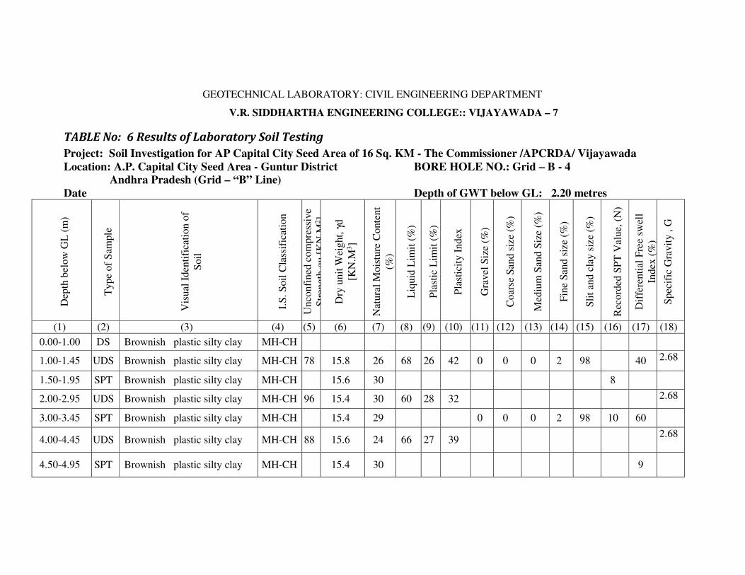
GEOTECHNICAL LABORATORY: CIVIL ENGINEERING DEPARTMENT
V.R. SIDDHARTHA ENGINEERING COLLEGE:: VIJAYAWADA – 7
TABLE No: 6 Results of Laboratory Soil Testing
Project: Soil Investigation for AP Capital City Seed Area of 16 Sq. KM - The Commissioner /APCRDA/ Vijayawada
Location: A.P. Capital City Seed Area - Guntur District BORE HOLE NO.: Grid – B - 4
Andhra Pradesh (Grid – “B” Line)
Date Depth of GWT below GL: 2.20 metres
Dep
th b
elo
w G
L (
m)
Type
of
Sam
ple
Vis
ual
Iden
tifi
cati
on o
f
Soil
I.S
. S
oil
Cla
ssif
icat
ion
Unco
nfi
ned c
om
pre
ssiv
e
Str
ength
qu [
KN
.M2]
Dry
unit
Wei
ght,
γd
[KN
.M3]
Nat
ura
l M
ois
ture
Conte
nt
(%)
Liq
uid
Lim
it (
%)
Pla
stic
Lim
it (
%)
Pla
stic
ity I
ndex
Gra
vel
Siz
e (%
)
Coar
se S
and s
ize
(%)
Med
ium
San
d S
ize
(%)
Fin
e S
and s
ize
(%)
Sli
t an
d c
lay s
ize
(%)
Rec
ord
ed S
PT
Valu
e, (
N)
Dif
fere
nti
al F
ree
swel
l
Index (
%)
Spec
ific
Gra
vit
y , G
(1) (2) (3) (4) (5) (6) (7) (8) (9) (10) (11) (12) (13) (14) (15) (16) (17) (18)
0.00-1.00 DS Brownish plastic silty clay MH-CH
1.00-1.45 UDS Brownish plastic silty clay MH-CH 78 15.8 26 68 26 42 0 0 0 2 98 40 2.68
1.50-1.95 SPT Brownish plastic silty clay MH-CH 15.6 30 8
2.00-2.95 UDS Brownish plastic silty clay MH-CH 96 15.4 30 60 28 32 2.68
3.00-3.45 SPT Brownish plastic silty clay MH-CH 15.4 29 0 0 0 2 98 10 60
4.00-4.45 UDS Brownish plastic silty clay MH-CH 88 15.6 24 66 27 39 2.68
4.50-4.95 SPT Brownish plastic silty clay MH-CH 15.4 30 9
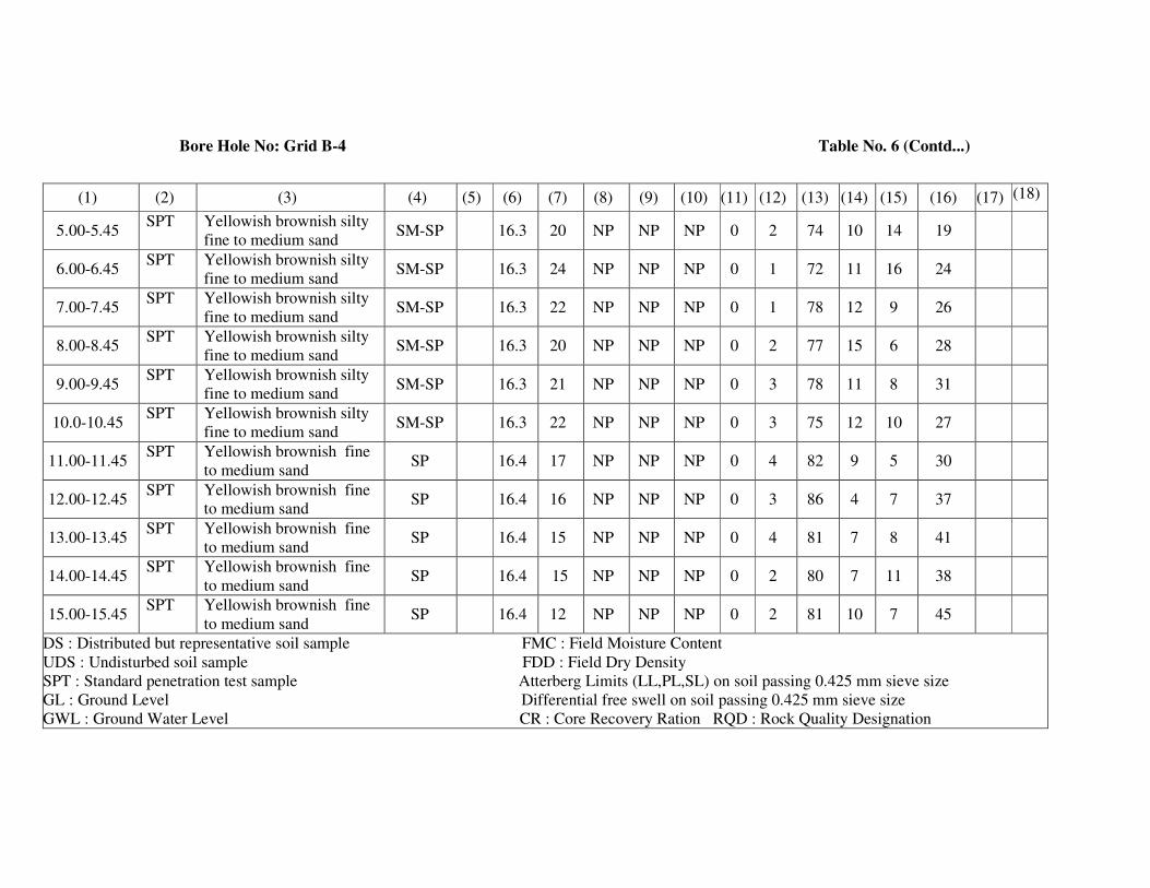
Bore Hole No: Grid B-4 Table No. 6 (Contd...)
(1) (2) (3) (4) (5) (6) (7) (8) (9) (10) (11) (12) (13) (14) (15) (16) (17) (18)
5.00-5.45 SPT Yellowish brownish silty
fine to medium sand SM-SP 16.3 20 NP NP NP 0 2 74 10 14 19
6.00-6.45 SPT Yellowish brownish silty
fine to medium sand SM-SP 16.3 24 NP NP NP 0 1 72 11 16 24
7.00-7.45 SPT Yellowish brownish silty
fine to medium sand SM-SP 16.3 22 NP NP NP 0 1 78 12 9 26
8.00-8.45 SPT Yellowish brownish silty
fine to medium sand SM-SP 16.3 20 NP NP NP 0 2 77 15 6 28
9.00-9.45 SPT Yellowish brownish silty
fine to medium sand SM-SP 16.3 21 NP NP NP 0 3 78 11 8 31
10.0-10.45 SPT Yellowish brownish silty
fine to medium sand SM-SP 16.3 22 NP NP NP 0 3 75 12 10 27
11.00-11.45 SPT Yellowish brownish fine
to medium sand SP 16.4 17 NP NP NP 0 4 82 9 5 30
12.00-12.45 SPT Yellowish brownish fine
to medium sand SP 16.4 16 NP NP NP 0 3 86 4 7 37
13.00-13.45 SPT Yellowish brownish fine
to medium sand SP 16.4 15 NP NP NP 0 4 81 7 8 41
14.00-14.45 SPT Yellowish brownish fine
to medium sand SP 16.4 15 NP NP NP 0 2 80 7 11 38
15.00-15.45 SPT Yellowish brownish fine
to medium sand SP 16.4 12 NP NP NP 0 2 81 10 7 45
DS : Distributed but representative soil sample FMC : Field Moisture Content
UDS : Undisturbed soil sample FDD : Field Dry Density
SPT : Standard penetration test sample Atterberg Limits (LL,PL,SL) on soil passing 0.425 mm sieve size
GL : Ground Level Differential free swell on soil passing 0.425 mm sieve size
GWL : Ground Water Level CR : Core Recovery Ration RQD : Rock Quality Designation

GEOTECHNICAL LABORATORY: CIVIL ENGINEERING DEPARTMENT V.R. SIDDHARTHA ENGINEERING COLLEGE:: VIJAYAWADA – 7
TABLE: 7 Idealized Design Soil Parameters
Project: Soil Investigation for AP Capital City Seed Area of 16 Sq. KM - The Commissioner /APCRDA/ Vijayawada
Location: A.P. Capital City Seed Area - Guntur District BORE HOLE NO.: Grid – B - 5
Andhra Pradesh (Grid – “B” Line)
Reduced level of the Bore hole = Depth of Water level: 2.00 metres Depth below
the existing
ground level
(metres)
Visual Identification of soil I.S. Soil
Classification
Natural
Moisture
Content
(%)
Dry
Unit
Weight [KN/m3]
Recorded
SPT value
(N)
Un confined
Compressive
Strength, qc [KN/m2]
Shear Parameters Safe bearing
Capacity
[KN/m2] Cohesion C
[KN/m2] φ
(deg)
0.00-2.50 Brownish plastic silty clay MH-CH 26,28 15.60
15.50 UDS,8 78 39 0 80
2.50-3.90 Brownish plastic silty clay
MH-CH 24,26 16.0
15.9 UDS,10 98 49 0 100
3.90-7.00 Yellowish brownish silty
fine to medium sand SM-SP 18,19 16.20 12,16,17
[Es = 500
kg/cm2] 0 33 175
7.00-11.00 Yellowish brownish fine to
medium sand SP 19 16.30
20,21,23
27
[Es = 550
kg/cm2] 0 34 200
1100-14.60 Yellowish brownish fine to
medium sand SP 17 16.40
33,38
37,40
[Es = 600
kg/cm2] 0 36 225
14.60-15.50 Blackish brown plastic silty
clay MH-CH 34 15.2 28 248 124 0 250
qc = Unconfined compressive strength
Es = Modulus of Soil
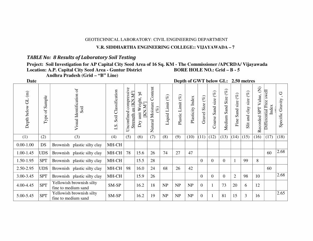
GEOTECHNICAL LABORATORY: CIVIL ENGINEERING DEPARTMENT
V.R. SIDDHARTHA ENGINEERING COLLEGE:: VIJAYAWADA – 7
TABLE No: 8 Results of Laboratory Soil Testing
Project: Soil Investigation for AP Capital City Seed Area of 16 Sq. KM - The Commissioner /APCRDA/ Vijayawada
Location: A.P. Capital City Seed Area - Guntur District BORE HOLE NO.: Grid – B - 5
Andhra Pradesh (Grid – “B” Line)
Date Depth of GWT below GL: 2.50 metres
Dep
th b
elow
GL
(m
)
Type
of
Sam
ple
Vis
ual
Iden
tifi
cati
on o
f
Soil
I.S
. S
oil
Cla
ssif
icat
ion
Unco
nfi
ned c
om
pre
ssiv
e
Str
ength
qu [
KN
.M2]
Dry
unit
Wei
ght,
γd
[KN
.M3]
Natu
ral
Mois
ture
Conte
nt
(%)
Liq
uid
Lim
it (
%)
Pla
stic
Lim
it (
%)
Pla
stic
ity I
ndex
Gra
vel
Siz
e (%
)
Coar
se S
and s
ize
(%)
Med
ium
San
d S
ize
(%)
Fin
e S
and s
ize
(%)
Sli
t an
d c
lay s
ize
(%)
Rec
ord
ed S
PT
Valu
e, (
N)
Dif
fere
nti
al F
ree
swel
l
Index
(%)
Spec
ific
Gra
vit
y , G
(1) (2) (3) (4) (5) (6) (7) (8) (9) (10) (11) (12) (13) (14) (15) (16) (17) (18)
0.00-1.00 DS Brownish plastic silty clay MH-CH
1.00-1.45 UDS Brownish plastic silty clay MH-CH 78 15.6 26 74 27 47 60 2.68
1.50-1.95 SPT Brownish plastic silty clay MH-CH 15.5 28 0 0 0 1 99 8
2.50-2.95 UDS Brownish plastic silty clay MH-CH 98 16.0 24 68 26 42 60
3.00-3.45 SPT Brownish plastic silty clay MH-CH 15.9 26 0 0 0 2 98 10 2.68
4.00-4.45 SPT Yellowish brownish silty
fine to medium sand SM-SP 16.2 18 NP NP NP 0 1 73 20 6 12
5.00-5.45 SPT Yellowish brownish silty
fine to medium sand SM-SP 16.2 19 NP NP NP 0 1 81 15 3 16
2.65
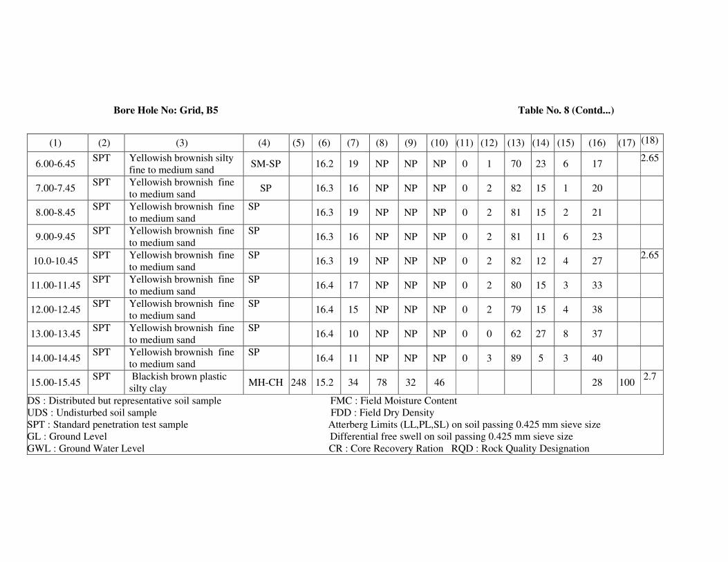
Bore Hole No: Grid, B5 Table No. 8 (Contd...)
(1) (2) (3) (4) (5) (6) (7) (8) (9) (10) (11) (12) (13) (14) (15) (16) (17) (18)
6.00-6.45 SPT Yellowish brownish silty
fine to medium sand SM-SP 16.2 19 NP NP NP 0 1 70 23 6 17
2.65
7.00-7.45 SPT Yellowish brownish fine
to medium sand SP 16.3 16 NP NP NP 0 2 82 15 1 20
8.00-8.45 SPT Yellowish brownish fine
to medium sand
SP 16.3 19 NP NP NP 0 2 81 15 2 21
9.00-9.45 SPT Yellowish brownish fine
to medium sand
SP 16.3 16 NP NP NP 0 2 81 11 6 23
10.0-10.45 SPT Yellowish brownish fine
to medium sand
SP 16.3 19 NP NP NP 0 2 82 12 4 27
2.65
11.00-11.45 SPT Yellowish brownish fine
to medium sand
SP 16.4 17 NP NP NP 0 2 80 15 3 33
12.00-12.45 SPT Yellowish brownish fine
to medium sand
SP 16.4 15 NP NP NP 0 2 79 15 4 38
13.00-13.45 SPT Yellowish brownish fine
to medium sand
SP 16.4 10 NP NP NP 0 0 62 27 8 37
14.00-14.45 SPT Yellowish brownish fine
to medium sand
SP 16.4 11 NP NP NP 0 3 89 5 3 40
15.00-15.45 SPT Blackish brown plastic
silty clay MH-CH 248 15.2 34 78 32 46 28 100
2.7
DS : Distributed but representative soil sample FMC : Field Moisture Content
UDS : Undisturbed soil sample FDD : Field Dry Density
SPT : Standard penetration test sample Atterberg Limits (LL,PL,SL) on soil passing 0.425 mm sieve size
GL : Ground Level Differential free swell on soil passing 0.425 mm sieve size
GWL : Ground Water Level CR : Core Recovery Ration RQD : Rock Quality Designation

GEOTECHNICAL LABORATORY: CIVIL ENGINEERING DEPARTMENT V.R. SIDDHARTHA ENGINEERING COLLEGE:: VIJAYAWADA – 7
TABLE: 9 Idealized Design Soil Parameters
Project: Soil Investigation for AP Capital City Seed Area of 16 Sq. KM - The Commissioner /APCRDA/ Vijayawada
Location: A.P. Capital City Seed Area - Guntur District BORE HOLE NO.: Grid – C - 4
Andhra Pradesh (Grid – “C” Line)
Reduced level of the Bore hole = Depth of Water level: 2.70 metres Depth below
the existing
ground level
(metres)
Visual Identification of soil
I.S. Soil
Classific
ation
Natural
Moisture
Content
(%)
Dry
Unit
Weight [KN/m3]
Recorded
SPT value
(N)
Un confined
Compressive
Strength,qc [KN/m2]
Shear Parameters Safe bearing
Capacity
[KN/m2] Cohesion C
[KN/m2] φ
(deg)
0.00-2.50 Brownish plastic silty clay MH-CH 33 14.50 UDS,7 78 39 0 80
2.50-4.00 Brownish plastic silty clay MH-CH 32 14.80 UDS,10 106 53 0 110
4.00-5.50 Brownish plastic silty clay MH-CH 28 15.40 UDS,12 116 58 0 120
5.50-6.90 Brownish plastic silty clay MH-CH 30 15.40 UDS,13 128 64 0 130
6.90-8.70 Yellowish brownish silty fine to
medium sand
SM-SP 18 16.30 21,25 [Es = 550
kg/cm2]
0 34 200
8.70-11.00 Yellowish brownish plastic silty
clay
MH-CH 24,30 15.40 15,17 160 80 0 160
11.00-14.00 Blackish brown plastic silty clay MH-CH 39 14.00 14,UDS,15 140 70 0 140
14.00-15.50 Blackish brown plastic silty clay MH-CH 40 14.10 17,21 178 89 0 180
Consolidation Test Results: qc = Unconfined compressive strength
Es = Modulus of Soil
Depth = 12.0 – 12.45 m
NMC = 39% ; γd = 14.0 kN/m3; G = 2.70; Initial void ratio, eo = 1.053
Compression Index= Cc=0.320; Pre consolidation Pressure, Po=0.50 kg/cm2
Modulus of soil (Es) = 500 kg/cm2
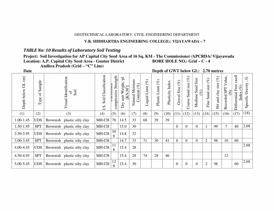
GEOTECHNICAL LABORATORY: CIVIL ENGINEERING DEPARTMENT
V.R. SIDDHARTHA ENGINEERING COLLEGE:: VIJAYAWADA – 7
TABLE No: 10 Results of Laboratory Soil Testing
Project: Soil Investigation for AP Capital City Seed Area of 16 Sq. KM - The Commissioner /APCRDA/ Vijayawada
Location: A.P. Capital City Seed Area - Guntur District BORE HOLE NO.: Grid – C - 4
Andhra Pradesh (Grid – “C” Line)
Date Depth of GWT below GL: 2.70 metres
Dep
th b
elow
GL
(m
)
Type
of
Sam
ple
Vis
ual
Identi
fica
tion
of
Soil
I.S
. S
oil
Cla
ssif
icat
ion
Unco
nfi
ned
com
pre
ssiv
e S
tren
gth
qu [
KN
.M2]
Dry
unit
Weig
ht,
γd
[KN
.M3]
Nat
ura
l M
ois
ture
Conte
nt
(%)
Liq
uid
Lim
it (
%)
Pla
stic
Lim
it (
%)
Pla
stic
ity I
ndex
Gra
vel
Siz
e (%
)
Coars
e S
and s
ize
(%)
Mediu
m S
and S
ize
(%)
Fin
e S
and s
ize
(%)
Sli
t an
d c
lay s
ize
(%)
Rec
ord
ed S
PT
Val
ue,
(N)
Dif
fere
nti
al F
ree
swel
l
Index
(%
)
Spec
ific
Gra
vit
y , G
(1) (2) (3) (4) (5) (6) (7) (8) (9) (10) (11) (12) (13) (14) (15) (16) (17) (18)
1.00-1.45 UDS Brownish plastic silty clay MH-CH 78 14.5 33 68 29 39
1.50-1.95 SPT Brownish plastic silty clay MH-CH 15.0 30 0 0 0 1 99 7 40 2.68
2.50-2.95 UDS Brownish plastic silty clay MH-CH 10
6 14.8 32
3.00-3.45 SPT Brownish plastic silty clay MH-CH 14.7 33 71 30 41 0 0 0 2 98 10 60
4.00-4.45 UDS Brownish plastic silty clay MH-CH 11
6 15.4 28
2.68
4.50-4.95 SPT Brownish plastic silty clay MH-CH 15.4 28 74 28 46 12
5.00-5.45 UDS Brownish plastic silty clay MH-CH 12
8 15.4 30 0 0 0 2 98 60
2.68
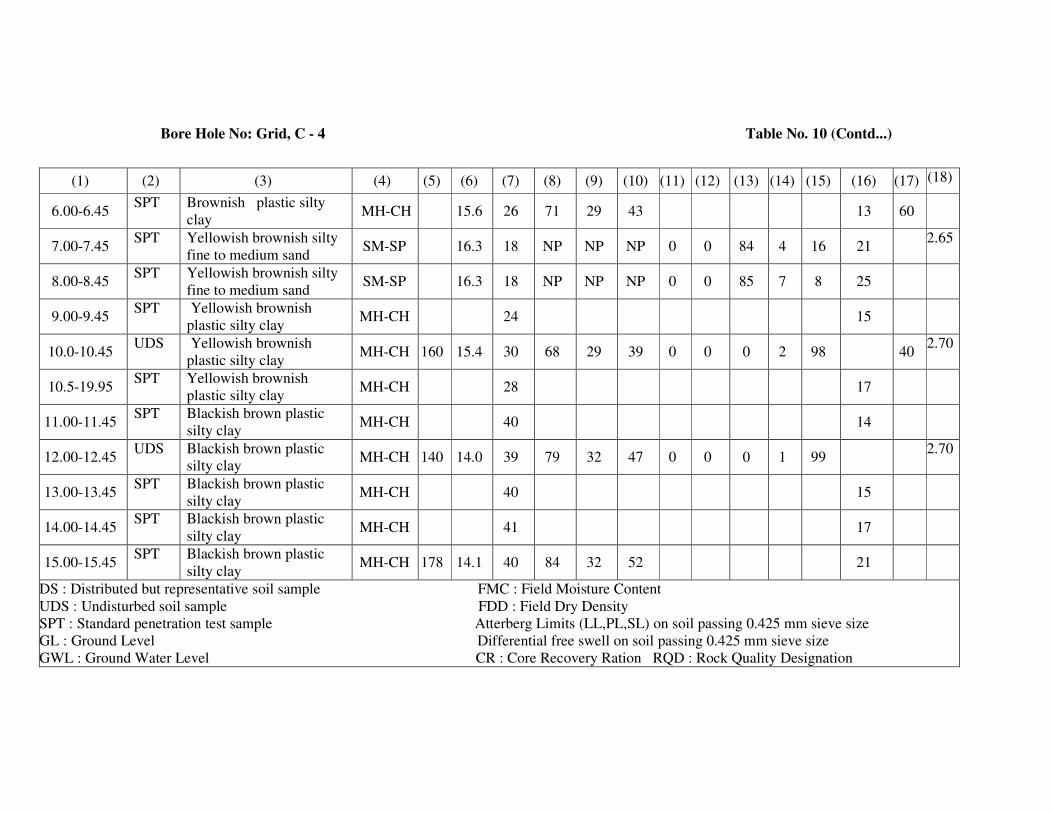
Bore Hole No: Grid, C - 4 Table No. 10 (Contd...)
(1) (2) (3) (4) (5) (6) (7) (8) (9) (10) (11) (12) (13) (14) (15) (16) (17) (18)
6.00-6.45 SPT Brownish plastic silty
clay MH-CH 15.6 26 71 29 43 13 60
7.00-7.45 SPT Yellowish brownish silty
fine to medium sand SM-SP 16.3 18 NP NP NP 0 0 84 4 16 21
2.65
8.00-8.45 SPT Yellowish brownish silty
fine to medium sand SM-SP 16.3 18 NP NP NP 0 0 85 7 8 25
9.00-9.45 SPT Yellowish brownish
plastic silty clay MH-CH 24 15
10.0-10.45 UDS Yellowish brownish
plastic silty clay MH-CH 160 15.4 30 68 29 39 0 0 0 2 98 40
2.70
10.5-19.95 SPT Yellowish brownish
plastic silty clay MH-CH 28 17
11.00-11.45 SPT Blackish brown plastic
silty clay MH-CH 40 14
12.00-12.45 UDS Blackish brown plastic
silty clay MH-CH 140 14.0 39 79 32 47 0 0 0 1 99
2.70
13.00-13.45 SPT Blackish brown plastic
silty clay MH-CH 40 15
14.00-14.45 SPT Blackish brown plastic
silty clay MH-CH 41 17
15.00-15.45 SPT Blackish brown plastic
silty clay MH-CH 178 14.1 40 84 32 52 21
DS : Distributed but representative soil sample FMC : Field Moisture Content
UDS : Undisturbed soil sample FDD : Field Dry Density
SPT : Standard penetration test sample Atterberg Limits (LL,PL,SL) on soil passing 0.425 mm sieve size
GL : Ground Level Differential free swell on soil passing 0.425 mm sieve size
GWL : Ground Water Level CR : Core Recovery Ration RQD : Rock Quality Designation

GEOTECHNICAL LABORATORY: CIVIL ENGINEERING DEPARTMENT V.R. SIDDHARTHA ENGINEERING COLLEGE:: VIJAYAWADA – 7
TABLE: 11 Idealized Design Soil Parameters
Project: Soil Investigation for AP Capital City Seed Area of 16 Sq. KM - The Commissioner /APCRDA/ Vijayawada
Location: A.P. Capital City Seed Area - Guntur District BORE HOLE NO.: Grid – C - 5
Andhra Pradesh (Grid – “C” Line)
Reduced level of the Bore hole = Depth of Water level: 2.40 metres Depth below
the existing
ground level
(metres)
Visual Identification of soil
I.S. Soil
Classifica
tion
Natural
Moisture
Content
(%)
Dry
Unit
Weight [KN/m3]
Recorded
SPT value
(N)
Un confined
Compressive
Strength,qc [KN/m2]
Shear Parameters Safe bearing
Capacity
[KN/m2] Cohesion C
[KN/m2] φ
(deg)
0.00-2.50 Brownish plastic silty clay MH-CH 25 15.10 UDS,10 108 54 0 110
2.50-4.00 Brownish plastic silty clay MH-CH 26 15.40 UDS,14 138 69 0 140
4.00-5.00 Brownish plastic silty clay
MH-CH 30 15.50 UDS,17 164 82 0 170
5.00-8.00 Yellowish brownish silty fine to
medium sand SM-SP 20 16.30 16,21,24
[Es = 550
kg/cm2] 0 34 200
8.00-11.40 Yellowish brownish silty fine to
medium sand SM-SP 20 16.40
33,37
38,39
[Es = 600
kg/cm2] 0 36 225
11.40-14.00 Yellowish brownish plastic silty
clay MH-CH 30 15.50 12,UDS 120 60 0 120
14.00-15.50 Blackish brown plastic silty clay MH-CH 28,31 15.40 14,UDS 148 74 0 150
Consolidation Test Results: qc = Unconfined compressive strength
Es = Modulus of Soil
Depth = 15.0 – 15.45 m
NMC = 31% ; γd = 15.4 kN/m3; G = 2.70; Initial void ratio, eo = 0.840
Compression Index= Cc=0.236; Pre consolidation Pressure, Po=0.75 kg/cm2
Modulus of soil (Es) = 600 kg/cm2

GEOTECHNICAL LABORATORY: CIVIL ENGINEERING DEPARTMENT
V.R. SIDDHARTHA ENGINEERING COLLEGE:: VIJAYAWADA – 7
TABLE No: 12 Results of Laboratory Soil Testing
Project: Soil Investigation for AP Capital City Seed Area of 16 Sq. KM - The Commissioner /APCRDA/ Vijayawada
Location: A.P. Capital City Seed Area - Guntur District BORE HOLE NO.: Grid – C - 5
Andhra Pradesh (Grid – “C” Line)
Date Depth of GWT below GL: 2.40 metres
Depth
bel
ow
GL
(m
)
Type
of
Sam
ple
Vis
ual
Identi
fica
tion o
f
Soil
I.S
. S
oil
Cla
ssif
icat
ion
Unco
nfi
ned
com
pre
ssiv
e
Str
ength
qu [
KN
.M2]
Dry
unit
Wei
ght,
γd
[KN
.M3]
Nat
ura
l M
ois
ture
Conte
nt
(%)
Liq
uid
Lim
it (
%)
Pla
stic
Lim
it (
%)
Pla
stic
ity I
ndex
Gra
vel
Siz
e (%
)
Coars
e S
and s
ize
(%)
Mediu
m S
and S
ize
(%)
Fin
e S
and s
ize
(%)
Sli
t and c
lay s
ize
(%)
Rec
ord
ed S
PT
Val
ue,
(N
)
Dif
fere
nti
al F
ree
swel
l
Index
(%
)
Speci
fic
Gra
vit
y , G
(1) (2) (3) (4) (5) (6) (7) (8) (9) (10) (11) (12) (13) (14) (15) (16) (17) (18)
1.00-1.45 UDS Brownish plastic silty clay MH-CH 108 15.1 25 67 26 41
1.50-1.95 SPT Brownish plastic silty clay MH-CH 15.1 26 0 0 0 1 99 10 80 2.68
2.50-2.95 UDS Brownish plastic silty clay MH-CH 138 15.4 26 70 28 42
3.00-3.45 SPT Brownish plastic silty clay MH-CH 15.4 28 0 0 0 2 98 14
4.00-4.45 UDS Brownish plastic silty clay MH-CH 164 15.5 30 74 30 44 80 2.68
4.50-4.95 SPT Brownish plastic silty clay MH-CH 15.7 25 0 0 0 2 98 17
5.00-5.45 SPT Yellowish brownish silty
fine to medium sand SM-SP 16.3 19 NP NP NP 0 0 83 14 3 16
2.65

Bore Hole No: Grid, C-5 Table No. 12 (Contd...)
(1) (2) (3) (4) (5) (6) (7) (8) (9) (10) (11) (12) (13) (14) (15) (16) (17) (18)
6.00-6.45 SPT Yellowish brownish silty
fine to medium sand SM-SP 16.3 20 NP NP NP 0 0 79 14 7 21
7.00-7.45 SPT Yellowish brownish silty
fine to medium sand SM-SP 16.3 18 NP NP NP 0 0 82 12 6 24
8.00-8.45 SPT Yellowish brownish silty
fine to medium sand SM-SP 16.4 19 NP NP NP 0 0 75 17 8 33
2.65
9.00-9.45 SPT Yellowish brownish silty
fine to medium sand SM-SP 16.4 20 NP NP NP 0 0 77 15 2 37
10.0-10.45 SPT Yellowish brownish silty
fine to medium sand SM-SP 16.4 20 NP NP NP 0 0 72 21 7 38
11.00-11.45 SPT Yellowish brownish silty
fine to medium sand SM-SP 16.4 18 NP NP NP 0 0 75 19 6 39
12.00-12.45 UDS Yellowish brownish
plastic silty clay MH-CH 30 12
2.70
13.00-13.45 SPT Yellowish brownish
plastic silty clay MH-CH 120 15.5 30 69 27 42 0 0 0 2 98 40
14.00-14.45 SPT Blackish brown plastic
silty clay MH-CH 15.6 28 14
15.00-15.45 SPT Blackish brown plastic
silty clay MH-CH 148 15.4 31 78 30 48
DS : Distributed but representative soil sample FMC : Field Moisture Content
UDS : Undisturbed soil sample FDD : Field Dry Density
SPT : Standard penetration test sample Atterberg Limits (LL,PL,SL) on soil passing 0.425 mm sieve size
GL : Ground Level Differential free swell on soil passing 0.425 mm sieve size
GWL : Ground Water Level CR : Core Recovery Ration RQD : Rock Quality Designation

8 CONCLUSIONS
Based on the field and laboratory test results, the following recommendations are made
for the APCRDA Capital City SEED Area of 16 Sq. KM in Guntur District, Andhra
Pradesh [ [For Grid A-4, 5; B-4, 5 & C- 4, 5 bore holes].
• The soil Profile consists of three layers of varying thickness.
• The top layer is residual soil namely brownish plastic silty clay [MH-CH].
• The middle layer is alluvial soil namely sand [SP].
• The bottom layer is stiff silty clay [MH-CH] and over consolidated.
• The soil profile at different locations is given in Figure 1 to 6 for various bore
hole locations namely A-4, 5 ; B- 4, 5 and C- 4, 5.
• The physical properties of soil at different depth and location are given in Tables
1 to 12.
• The safe bearing capacity of soil at different depth and location is given in Table
1, 3, 5, 7, 9 and 13.
• Suitable foundation may be selected from the soil profile and requirement.
Dr N R Krishnamurthy
Professor Professor & Head Dean/Principal
SUB SOIL PROFILES
A -6, A -7, A-8
B -6, B -7, B-8
C -6, C -7, C-8

6 SUB SOIL PROFILES
The Sub soil profile at the bore hole locations, based on the identification of soil
samples and the results of tests (both field and laboratory) are indicated in Figure: 1 -9. The
idealized design soil parameters are given in Table 1, 3, 5, 7, 9 , 11, 13, 15, and 17.
6.1 Bore Hole Number: Grid A- 6 Ground Water Level = 2.60 m
Depth Below
G.L.(metres)
Soil Type and Classification Recorded SPT
“N” Value
0.00 – 2.00 Brownish Plastic silty clay [MH - CH] qc= 86 kN/m2
2.00 – 3.75 Yellowish brown plastic silty clay [MH-CH] UDS, 10
3.75 – 8.00 Yellowish brown silty fine to medium sand [SM-SP] 11, 12, 16, 19
8.00 – 15.50 Yellowish brown fine to medium sand [SP] 25, 29, 34
35, 40, 42
6.2 Bore Hole Number: Grid A- 7 Ground Water Level = 3.00 m
Depth Below
G.L.(metres)
Soil Type and Classification Recorded SPT
“N” Value
0.00 – 2.00 Brownish plastic silty clay [MH - CH] qc =124 kN/m2
2.00 – 3.00 Brownish plastic silty clay [MH-CH] qc =142 kN/m2
3.00 – 4.00 Yellowish brown silty fine to medium sand [SM-SP] 19
4.00 – 5.00 Yellowish brown plastic sandy silty clay [MH-CH] UDS, 24
5.00 – 10.00 Yellowish brown silty fine to medium sand [SM-SP] 28,36,33,34,35
10.00 – 15.50 Yellowish brown silty fine to medium sand [SM-SP] 37,44,48,45,50
6.3 Bore Hole Number: Grid A-8 Ground Water Level = 3.80 m
Depth Below
G.L.(metres)
Soil Type and Classification Recorded SPT
“N” Value
0.00 – 2.50 Brownish plastic silty clay [MH - CH] qc =126 kN/m2
2.50 – 4.00 Yellowish brown plastic silty clay [MH - CH] UDS, 15
4.00 – 5.00 Yellowish brown plastic silty clay [MH - CH] UDS, 18
5.00 – 9.00 Yellowish brown silty fine to medium sand [SM-SP] 20,23,18
9.00 – 12.00 Yellowish brown silty fine to medium sand [SM-SP] 33,34, 36
12.00 – 15.50 Yellowish brown silty fine to medium sand [SM-SP] 40,38, 42, 36
6.4 Bore Hole Number: Grid B- 6 Ground Water Level = 2.50 m
Depth Below Soil Type and Classification Recorded SPT

G.L.(metres) “N” Value
0.00 – 2.50 Brownish plastic silty clay [MH - CH] UDS, 6
2.50 – 5.00 Brownish plastic silty clay [MH - CH] UDS, 8
5.00 – 7.00 Yellowish brown fine to medium sand [SP] 14, 17
7.00 – 11.00 Yellowish brown fine to medium sand [SP] 22, 25, 29, 33
11.00 – 16.00 Yellowish brown fine to medium sand + pebbles 37,41,38,42,46
16.00– 18.70 Yellowish brown fine to medium sand + pebbles 39, 32, 33
18.70 – 21.00 Blackish plastic silty clay [MH-CH], stiff consistency UDS, 22
21.00 – 23.00 Blackish plastic silty clay [MH-CH], stiff consistency UDS, 28
23.00 – 25.00 Blackish plastic silty clay [MH-CH], stiff consistency UDS, 24
25.00 – 27.00 Yellowish brown sandy silty clay [MH-CH] UDS, 36
27.00 – 28.70 Yellowish brown silty fine to medium sand + pebbles 28, 33
28.70 – 30.00 Yellowish brown soft disintegrated rock [SDR] >100
6.5 Bore Hole Number: Grid B- 7 Ground Water Level = 2.00 m
Depth Below
G.L.(metres)
Soil Type and Classification Recorded SPT
“N” Value
0.00 – 2.50 Brownish plastic silty clay [MH - CH] UDS, 8
2.50 – 4.50 Brownish plastic silty clay [MH - CH] qc =118kN/m2
4.50 – 7.00 Yellowish brown fine to medium sand [SP] 16, 18
7.00 – 13.00 Yellowish brown fine to medium sand + pebbles, SP 18,20,22,20,25
13.00– 21.00 Yellowish brown fine to medium sand + pebbles, SP 29,33,40,42,45
21.00 – 23.00 Yellowish brown silty fine to medium sand [SM-SP] 30, 33
23.00 – 30.00 Yellowish brown fine to medium sand + pebbles, SP 37,40,45,47,50
6.6 Bore Hole Number: Grid B-8 Ground Water Level = 2.00 m
Depth Below
G.L.(metres)
Soil Type and Classification Recorded SPT
“N” Value
0.00 – 2.50 Brownish plastic silty clay [MH - CH] UDS, 6
2.50 – 5.00 Brownish plastic silty clay [MH - CH] UDS, 9, 12
5.00 – 10.00 Yellowish brown silty fine to medium sand [SM-SP] 18,16,19,22,24
10.00 – 15.50 Yellowish brown silty medium to fine sand [SM-SP] 28,31,35,36,41
6.7 Bore Hole Number: Grid C- 6 Ground Water Level = 2.80 m
Depth Below
G.L.(metres)
Soil Type and Classification Recorded SPT
“N” Value
0.00 – 1.50 Brownish plastic silty clay [MH - CH] UDS, 6
1.50 – 3.00 Brownish plastic silty clay [MH - CH] UDS, 10
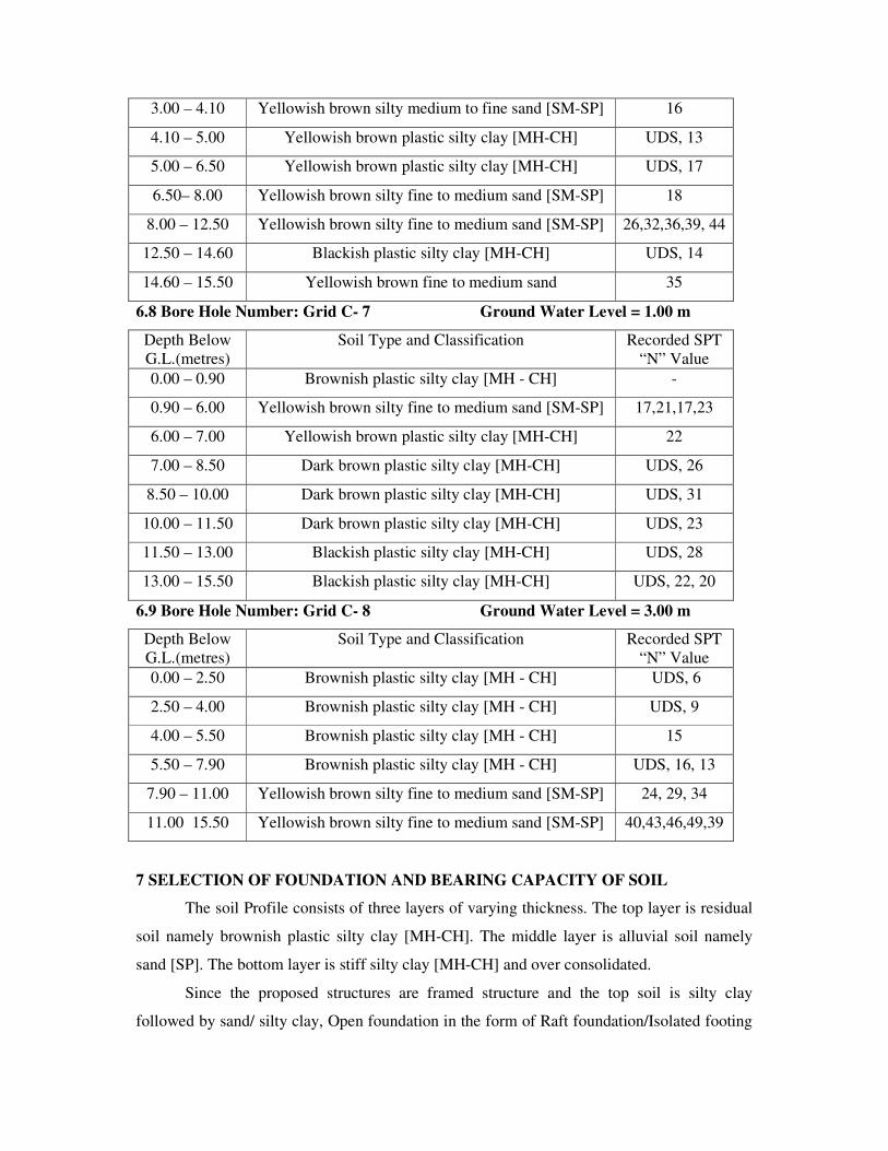
3.00 – 4.10 Yellowish brown silty medium to fine sand [SM-SP] 16
4.10 – 5.00 Yellowish brown plastic silty clay [MH-CH] UDS, 13
5.00 – 6.50 Yellowish brown plastic silty clay [MH-CH] UDS, 17
6.50– 8.00 Yellowish brown silty fine to medium sand [SM-SP] 18
8.00 – 12.50 Yellowish brown silty fine to medium sand [SM-SP] 26,32,36,39, 44
12.50 – 14.60 Blackish plastic silty clay [MH-CH] UDS, 14
14.60 – 15.50 Yellowish brown fine to medium sand 35
6.8 Bore Hole Number: Grid C- 7 Ground Water Level = 1.00 m
Depth Below
G.L.(metres)
Soil Type and Classification Recorded SPT
“N” Value
0.00 – 0.90 Brownish plastic silty clay [MH - CH] -
0.90 – 6.00 Yellowish brown silty fine to medium sand [SM-SP] 17,21,17,23
6.00 – 7.00 Yellowish brown plastic silty clay [MH-CH] 22
7.00 – 8.50 Dark brown plastic silty clay [MH-CH] UDS, 26
8.50 – 10.00 Dark brown plastic silty clay [MH-CH] UDS, 31
10.00 – 11.50 Dark brown plastic silty clay [MH-CH] UDS, 23
11.50 – 13.00 Blackish plastic silty clay [MH-CH] UDS, 28
13.00 – 15.50 Blackish plastic silty clay [MH-CH] UDS, 22, 20
6.9 Bore Hole Number: Grid C- 8 Ground Water Level = 3.00 m
Depth Below
G.L.(metres)
Soil Type and Classification Recorded SPT
“N” Value
0.00 – 2.50 Brownish plastic silty clay [MH - CH] UDS, 6
2.50 – 4.00 Brownish plastic silty clay [MH - CH] UDS, 9
4.00 – 5.50 Brownish plastic silty clay [MH - CH] 15
5.50 – 7.90 Brownish plastic silty clay [MH - CH] UDS, 16, 13
7.90 – 11.00 Yellowish brown silty fine to medium sand [SM-SP] 24, 29, 34
11.00 15.50 Yellowish brown silty fine to medium sand [SM-SP] 40,43,46,49,39
7 SELECTION OF FOUNDATION AND BEARING CAPACITY OF SOIL
The soil Profile consists of three layers of varying thickness. The top layer is residual
soil namely brownish plastic silty clay [MH-CH]. The middle layer is alluvial soil namely
sand [SP]. The bottom layer is stiff silty clay [MH-CH] and over consolidated.
Since the proposed structures are framed structure and the top soil is silty clay
followed by sand/ silty clay, Open foundation in the form of Raft foundation/Isolated footing
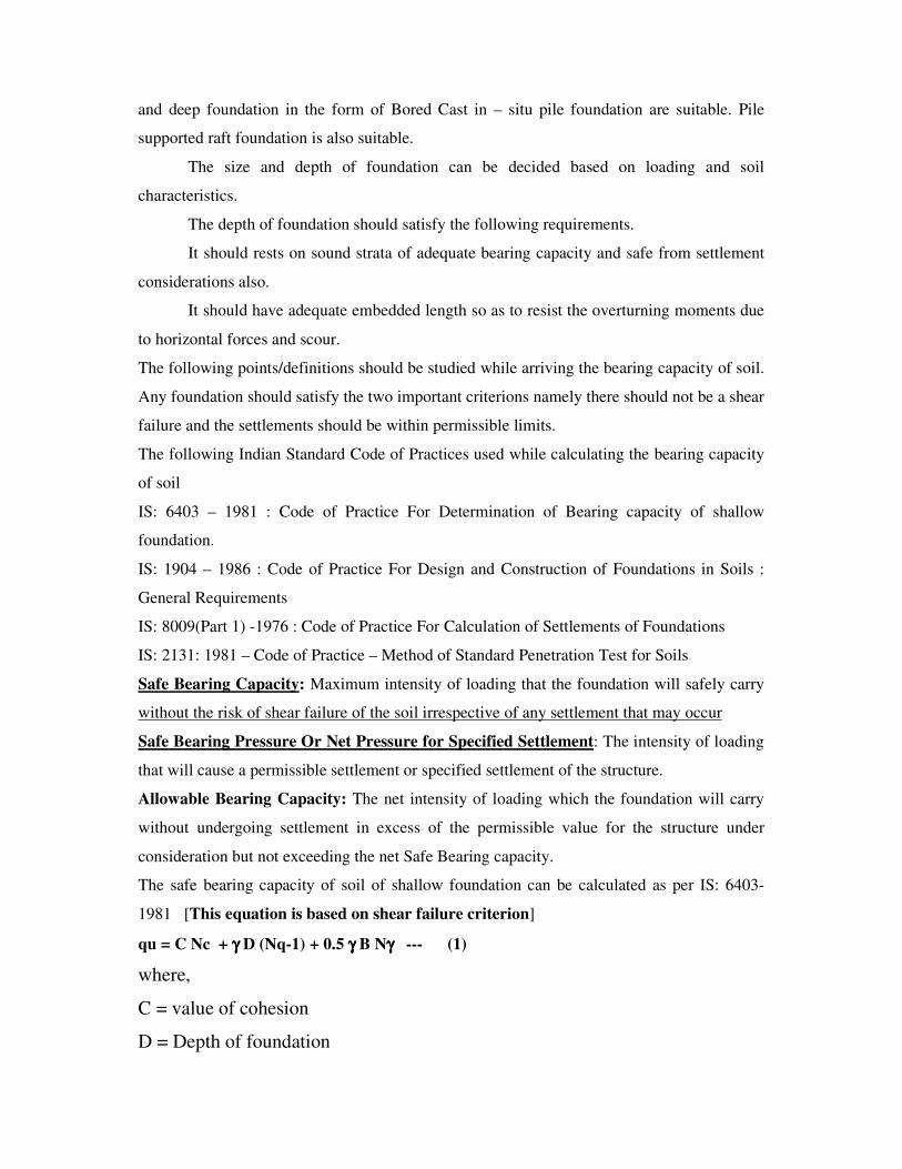
and deep foundation in the form of Bored Cast in – situ pile foundation are suitable. Pile
supported raft foundation is also suitable.
The size and depth of foundation can be decided based on loading and soil
characteristics.
The depth of foundation should satisfy the following requirements.
It should rests on sound strata of adequate bearing capacity and safe from settlement
considerations also.
It should have adequate embedded length so as to resist the overturning moments due
to horizontal forces and scour.
The following points/definitions should be studied while arriving the bearing capacity of soil.
Any foundation should satisfy the two important criterions namely there should not be a shear
failure and the settlements should be within permissible limits.
The following Indian Standard Code of Practices used while calculating the bearing capacity
of soil
IS: 6403 – 1981 : Code of Practice For Determination of Bearing capacity of shallow
foundation.
IS: 1904 – 1986 : Code of Practice For Design and Construction of Foundations in Soils :
General Requirements
IS: 8009(Part 1) -1976 : Code of Practice For Calculation of Settlements of Foundations
IS: 2131: 1981 – Code of Practice – Method of Standard Penetration Test for Soils
Safe Bearing Capacity: Maximum intensity of loading that the foundation will safely carry
without the risk of shear failure of the soil irrespective of any settlement that may occur
Safe Bearing Pressure Or Net Pressure for Specified Settlement: The intensity of loading
that will cause a permissible settlement or specified settlement of the structure.
Allowable Bearing Capacity: The net intensity of loading which the foundation will carry
without undergoing settlement in excess of the permissible value for the structure under
consideration but not exceeding the net Safe Bearing capacity.
The safe bearing capacity of soil of shallow foundation can be calculated as per IS: 6403-
1981 [This equation is based on shear failure criterion]
qu = C Nc + γγγγ D (Nq-1) + 0.5 γγγγ B Nγγγγ --- (1)
where,
C = value of cohesion
D = Depth of foundation

B = Size of the foundation
Nc, Nq & Nγ - Bearing capacity factors, depends on angle of internal friction, Ф
In clayey soil ie soil having only cohesion, C and Ф = 0; the bearing capacity
factors Nc = 5.14 ; Nq = 1 and Nγ = 0
qu = 5.14 C which indicates that the size of foundation is not having any effect of SBC. It
depends purely on shear strength of clay.
In Sandy soil ie soil having only Ф, the safe bearing capacity depends on Size and depth of
foundation. Nc, Nq and Nγ is highly sensitive to Ф . These factors increases with increasing
value of Ф [ Refer Table 1 of IS:6403 -1981]
The safe bearing capacity of soil will be, qs = qu /F.S.
Where, F.S. = factor of safety [ IS 6403 – 1981 recommends suitable factor of safety; refer
Section 6.1 of IS – 6403 – 1981; generally 3 for shallow foundation].
The following equation is used for the calculation of Safe settlement pressure in
Sandy soil as per IS 6403 – 1981 – Refer Clause 6.1 and 6.1.1
qa = 3.5 ( N-3 ) [(B+0.3)/2B]2 Rw Rd for settlement of 25 mm for Sand
This equation is a mathematical form derived from IS: 8009 (Part 1) - 1976
IS 6403 – 1981 specified the calculation of safe settlement pressure using the chart given
in IS-8009 (Part 1) – 1976 [ Figure 9 in Page No. : 17] and permissible settlements using
IS: 1904 – 1978.
In our calculations, in sand the SPT N value is corrected for overburden and
submergence and 40 mm total permissible settlement in sand is considered.
In general, the settlement pressure is the governing factor in the calculation of bearing
capacity of soil in sand. The shear failure criterion using the equation No.1 will give a
higher value
The allowable bearing capacity of soil is calculated as per IS 6403 specification considering
the shear failure and settlement failure criterion using the following equations.
qu = C Nc Sc Dc + γ D Nq Sq Dq Rw2 + 0.5 γ B NγSγDγRw2 ---- (1)
qa = 35 ( N-3 ) [(B+0.3)/2B]2 Rw Rd for settlement of 25 mm for sand (2)
Qa = 1.25 N for clayey soil (3)
The bearing capacity of soil at different depth is given in Table 1, 3, 5, 7, 9 & 11.
For Example: for Grid B – 6 Bore Hole
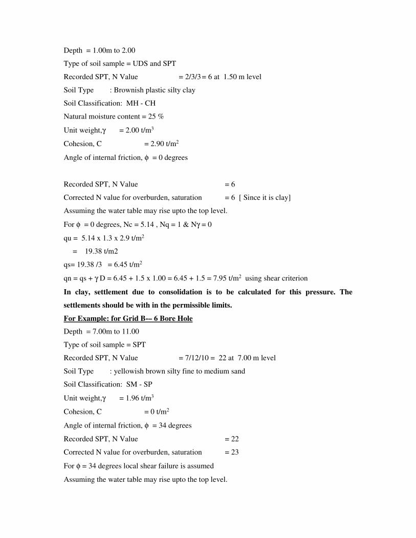
Depth = 1.00m to 2.00
Type of soil sample = UDS and SPT
Recorded SPT, N Value = 2/3/3 = 6 at 1.50 m level
Soil Type : Brownish plastic silty clay
Soil Classification: MH - CH
Natural moisture content = 25 %
Unit weight,γ = 2.00 t/m3
Cohesion, C = 2.90 t/m2
Angle of internal friction, φ = 0 degrees
Recorded SPT, N Value = 6
Corrected N value for overburden, saturation = 6 [ Since it is clay]
Assuming the water table may rise upto the top level.
For φ = 0 degrees, Nc = 5.14 , Nq = 1 & Nγ = 0
qu = 5.14 x 1.3 x 2.9 t/m2
= 19.38 t/m2
qs= 19.38 /3 = 6.45 t/m2
qn = qs + γ D = 6.45 + 1.5 x 1.00 = 6.45 + 1.5 = 7.95 t/m2 using shear criterion
In clay, settlement due to consolidation is to be calculated for this pressure. The
settlements should be with in the permissible limits.
For Example: for Grid B-– 6 Bore Hole
Depth = 7.00m to 11.00
Type of soil sample = SPT
Recorded SPT, N Value = 7/12/10 = 22 at 7.00 m level
Soil Type : yellowish brown silty fine to medium sand
Soil Classification: SM - SP
Unit weight,γ = 1.96 t/m3
Cohesion, C = 0 t/m2
Angle of internal friction, φ = 34 degrees
Recorded SPT, N Value = 22
Corrected N value for overburden, saturation = 23
For φ = 34 degrees local shear failure is assumed
Assuming the water table may rise upto the top level.
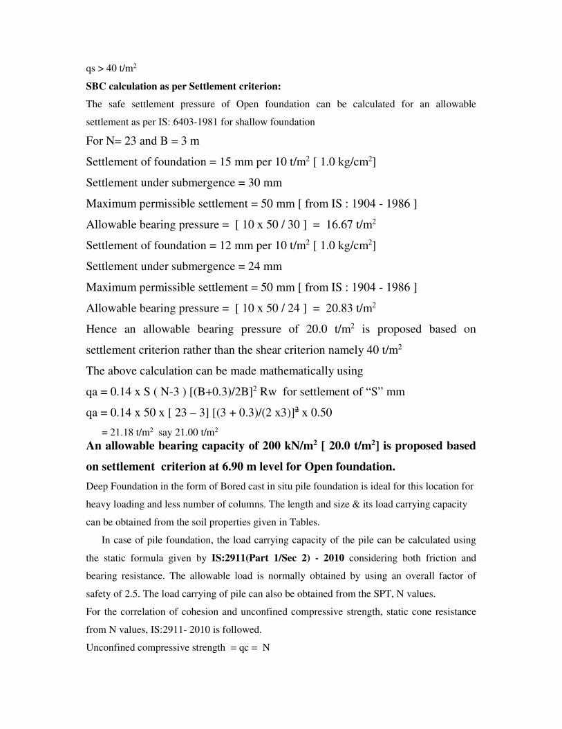
qs > 40 t/m2
SBC calculation as per Settlement criterion:
The safe settlement pressure of Open foundation can be calculated for an allowable
settlement as per IS: 6403-1981 for shallow foundation
For N= 23 and B = 3 m
Settlement of foundation = 15 mm per 10 t/m2 [ 1.0 kg/cm2]
Settlement under submergence = 30 mm
Maximum permissible settlement = 50 mm [ from IS : 1904 - 1986 ]
Allowable bearing pressure = [ 10 x 50 / 30 ] = 16.67 t/m2
Settlement of foundation = 12 mm per 10 t/m2 [ 1.0 kg/cm2]
Settlement under submergence = 24 mm
Maximum permissible settlement = 50 mm [ from IS : 1904 - 1986 ]
Allowable bearing pressure = [ 10 x 50 / 24 ] = 20.83 t/m2
Hence an allowable bearing pressure of 20.0 t/m2 is proposed based on
settlement criterion rather than the shear criterion namely 40 t/m2
The above calculation can be made mathematically using
qa = 0.14 x S ( N-3 ) [(B+0.3)/2B]2 Rw for settlement of “S” mm
qa = 0.14 x 50 x [ 23 – 3] [(3 + 0.3)/(2 x3)]2 x 0.50
= 21.18 t/m2 say 21.00 t/m2
An allowable bearing capacity of 200 kN/m2 [ 20.0 t/m2] is proposed based
on settlement criterion at 6.90 m level for Open foundation.
Deep Foundation in the form of Bored cast in situ pile foundation is ideal for this location for
heavy loading and less number of columns. The length and size & its load carrying capacity
can be obtained from the soil properties given in Tables.
In case of pile foundation, the load carrying capacity of the pile can be calculated using
the static formula given by IS:2911(Part 1/Sec 2) - 2010 considering both friction and
bearing resistance. The allowable load is normally obtained by using an overall factor of
safety of 2.5. The load carrying of pile can also be obtained from the SPT, N values.
For the correlation of cohesion and unconfined compressive strength, static cone resistance
from N values, IS:2911- 2010 is followed.
Unconfined compressive strength = qc = N
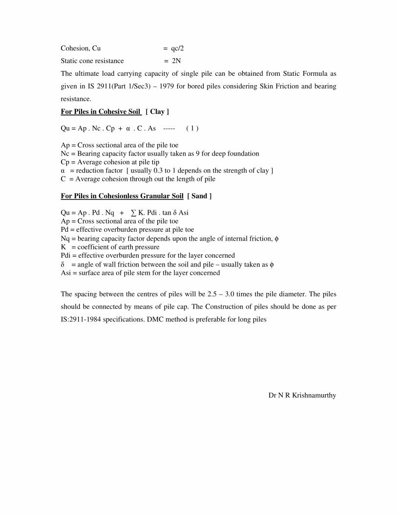
Cohesion, Cu = qc/2
Static cone resistance = 2N
The ultimate load carrying capacity of single pile can be obtained from Static Formula as
given in IS 2911(Part 1/Sec3) – 1979 for bored piles considering Skin Friction and bearing
resistance.
For Piles in Cohesive Soil [ Clay ]
Qu = Ap . Nc . Cp + α . C . As ----- ( 1 )
Ap = Cross sectional area of the pile toe
Nc = Bearing capacity factor usually taken as 9 for deep foundation
Cp = Average cohesion at pile tip
α = reduction factor [ usually 0.3 to 1 depends on the strength of clay ]
C = Average cohesion through out the length of pile
For Piles in Cohesionless Granular Soil [ Sand ]
Qu = Ap . Pd . Nq + ∑ K. Pdi . tan δ Asi
Ap = Cross sectional area of the pile toe
Pd = effective overburden pressure at pile toe
Nq = bearing capacity factor depends upon the angle of internal friction, φ
K = coefficient of earth pressure
Pdi = effective overburden pressure for the layer concerned
δ = angle of wall friction between the soil and pile – usually taken as φ
Asi = surface area of pile stem for the layer concerned
The spacing between the centres of piles will be 2.5 – 3.0 times the pile diameter. The piles
should be connected by means of pile cap. The Construction of piles should be done as per
IS:2911-1984 specifications. DMC method is preferable for long piles
Dr N R Krishnamurthy
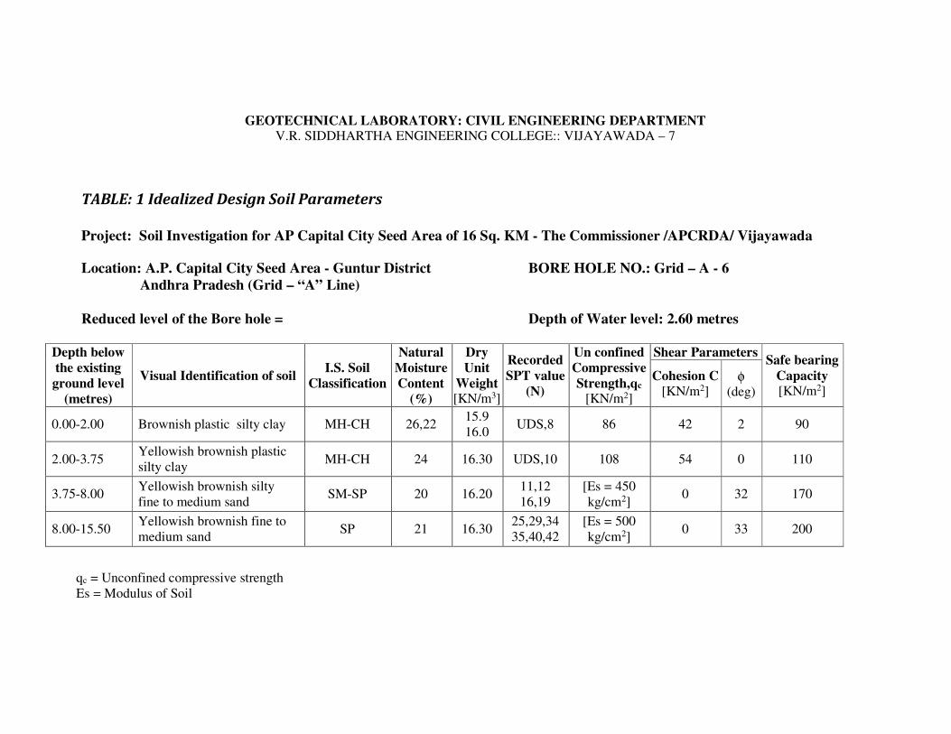
GEOTECHNICAL LABORATORY: CIVIL ENGINEERING DEPARTMENT V.R. SIDDHARTHA ENGINEERING COLLEGE:: VIJAYAWADA – 7
TABLE: 1 Idealized Design Soil Parameters
Project: Soil Investigation for AP Capital City Seed Area of 16 Sq. KM - The Commissioner /APCRDA/ Vijayawada
Location: A.P. Capital City Seed Area - Guntur District BORE HOLE NO.: Grid – A - 6
Andhra Pradesh (Grid – “A” Line)
Reduced level of the Bore hole = Depth of Water level: 2.60 metres
Depth below
the existing
ground level
(metres)
Visual Identification of soil I.S. Soil
Classification
Natural
Moisture
Content
(%)
Dry
Unit
Weight [KN/m3]
Recorded
SPT value
(N)
Un confined
Compressive
Strength,qc [KN/m2]
Shear Parameters Safe bearing
Capacity [KN/m2]
Cohesion C
[KN/m2] φ
(deg)
0.00-2.00 Brownish plastic silty clay MH-CH 26,22 15.9
16.0 UDS,8 86 42 2 90
2.00-3.75 Yellowish brownish plastic
silty clay MH-CH 24 16.30 UDS,10 108 54 0 110
3.75-8.00 Yellowish brownish silty
fine to medium sand SM-SP 20 16.20
11,12
16,19
[Es = 450
kg/cm2] 0 32 170
8.00-15.50 Yellowish brownish fine to
medium sand SP 21 16.30
25,29,34
35,40,42
[Es = 500
kg/cm2] 0 33 200
qc = Unconfined compressive strength
Es = Modulus of Soil

GEOTECHNICAL LABORATORY: CIVIL ENGINEERING DEPARTMENT
V.R. SIDDHARTHA ENGINEERING COLLEGE:: VIJAYAWADA – 7
TABLE No: 2 Results of Laboratory Soil Testing
Project: Soil Investigation for AP Capital City Seed Area of 16 Sq. KM - The Commissioner /APCRDA/ Vijayawada
Location: A.P. Capital City Seed Area - Guntur District BORE HOLE NO.: Grid – A - 6
Andhra Pradesh (Grid – “A” Line)
Date Depth of GWT below GL: 2.60 metres
Dep
th b
elow
GL
(m
)
Type
of
Sam
ple
Vis
ual
Identi
fica
tion o
f
Soil
I.S
. S
oil
Cla
ssif
icat
ion
Unco
nfi
ned
com
pre
ssiv
e
Str
ength
qu [
KN
.M2]
Dry
unit
Wei
ght,
γd [
KN
.M3]
Nat
ura
l M
ois
ture
Conte
nt
(%)
Liq
uid
Lim
it (
%)
Pla
stic
Lim
it (
%)
Pla
stic
ity I
ndex
Gra
vel
Siz
e (%
)
Coars
e S
and s
ize
(%)
Mediu
m S
and S
ize
(%)
Fin
e S
and s
ize
(%)
Sli
t and c
lay s
ize
(%)
Rec
ord
ed S
PT
Val
ue,
(N
)
Dif
fere
nti
al F
ree
swel
l In
dex
(%)
Spec
ific
Gra
vit
y,
G
(1) (2) (3) (4) (5) (6) (7) (8) (9) (10) (11) (12) (13) (14) (15) (16) (17) (18)
0.00-1.00 DS Brownish plastic silty clay MH-CH
1.00-1.45 UDS Brownish plastic silty clay MH-CH 86 15.90 26 64 26 38 0 0 0 2 98 60 2.68
1.50-1.95 SPT Brownish plastic silty clay MH-CH 16.0 22 8
2.00-2.95 UDS Yellowish brownish plastic
silty clay MH-CH 108 16.3 24 68 27 41 60
3.00-3.45 SPT Yellowish brownish plastic
silty clay MH-CH 16.3 23 0 0 0 4 96 10
2.67
4.00-4.45 SPT Yellowish brownish silty
fine to medium sand SM-SP 16.2 20 NP NP NP 0 0 42 43 5 11
5.00-5.45 SPT Yellowish brownish silty
fine to medium sand SM-SP 16.2 19 NP NP NP 0 0 80 13 7 12
2.65

Bore Hole No: Grid, A- 6 Table No.2 (Contd...)
(1) (2) (3) (4) (5) (6) (7) (8) (9) (10) (11) (12) (13) (14) (15) (16) (17) (18)
6.00-6.45 SPT Yellowish brownish silty
fine to medium sand SM-SP 16.2 17 NP NP NP 0 0 81 13 6 16
2.65
7.00-7.45 SPT Yellowish brownish silty
fine to medium sand SM-SP 16.2 16 NP NP NP 0 0 86 9 5 19
8.00-8.45 SPT Yellowish brownish fine to
medium sand
SP 16.3 16 NP NP NP 0 0 76 19 5 25
9.00-9.45 SPT Yellowish brownish fine to
medium sand
SP 16.3 21 NP NP NP 0 0 77 18 5 29
2.65
10.0-10.45 SPT Yellowish brownish fine to
medium sand
SP 16.3 17 NP NP NP 0 0 72 20 8 34
11.00-11.45 SPT Yellowish brownish fine to
medium sand
SP 16.3 18 NP NP NP 0 0 75 21 4 35
12.00-12.45 SPT Yellowish brownish fine to
medium sand
SP 16.3 17 NP NP NP 0 0 77 18 5 40
2.65
13.00-13.45 SPT Yellowish brownish fine to
medium sand
SP
16.2 14 NP NP NP 0 0 76 16 8 19
14.00-14.45 SPT Yellowish brownish fine to
medium sand
SP
16.3 14 NP NP NP 0 0 79 16 5 38
15.00-15.45 SPT Yellowish brownish fine to
medium sand
SP
16.3 18 NP NP NP 0 0 72 13 5 42
DS : Distributed but representative soil sample FMC : Field Moisture Content
UDS : Undisturbed soil sample FDD : Field Dry Density
SPT : Standard penetration test sample Atterberg Limits (LL,PL,SL) on soil passing 0.425 mm sieve size
GL : Ground Level Differential free swell on soil passing 0.425 mm sieve size
GWL : Ground Water Level CR : Core Recovery Ration RQD : Rock Quality Designation

GEOTECHNICAL LABORATORY: CIVIL ENGINEERING DEPARTMENT V.R. SIDDHARTHA ENGINEERING COLLEGE:: VIJAYAWADA – 7
TABLE: 3 Idealized Design Soil Parameters
Project: Soil Investigation for AP Capital City Seed Area of 16 Sq. KM - The Commissioner /APCRDA/ Vijayawada
Location: A.P. Capital City Seed Area - Guntur District BORE HOLE NO.: Grid – A - 7
Andhra Pradesh (Grid – “A” Line)
Reduced level of the Bore hole = Depth of Water level: 3.00 metres Depth below
the existing
ground level
(metres)
Visual Identification of soil I.S. Soil
Classification
Natural
Moisture
Content
(%)
Dry
Unit
Weight [KN/m3]
Recorded
SPT value
(N)
Un confined
Compressive
Strength, qc [KN/m2]
Shear Parameters Safe bearing
Capacity [KN/m2]
Cohesion C
[KN/m2] φ
(deg)
0.00-2.00 Brownish plastic silty clay MH-CH 25 15.9 UDS,13 124 62 0 125
2.00-3.00 Brownish plastic silty clay MH-CH 26 15.80 UDS 142 72 0 150
3.00-4.00 Yellowish brownish silty
fine to medium sand SM-SP 11 16.50 19
[Es = 600
kg/cm2] 0 36 250
4.00-5.00 Yellowish brownish plastic
sandy silty clay MH-CH 26 15.80 UDS,24 208 104 0 210
5.00-10.00 Yellowish brownish silty
fine to medium sand SM-SP 18,24 16.50
28,36,33
34,35
[Es = 600
kg/cm2] 0 36 250
10.00-15.00 Yellowish brownish silty
fine to medium sand SM-SP 10,14 16.50
37,44,48
45,50
[Es = 600
kg/cm2] 0 36 250
qc = Unconfined compressive strength
Es = Modulus of Soil

GEOTECHNICAL LABORATORY: CIVIL ENGINEERING DEPARTMENT
V.R. SIDDHARTHA ENGINEERING COLLEGE:: VIJAYAWADA – 7
TABLE No: 4 Results of Laboratory Soil Testing
Project: Soil Investigation for AP Capital City Seed Area of 16 Sq. KM - The Commissioner /APCRDA/ Vijayawada
Location: A.P. Capital City Seed Area - Guntur District BORE HOLE NO.: Grid – A - 7
Andhra Pradesh (Grid – “A” Line)
Date Depth of GWT below GL: 3.00 metres
Depth
bel
ow
GL
(m
)
Type
of
Sam
ple
Vis
ual
Identi
fica
tion o
f
Soil
I.S
. S
oil
Cla
ssif
icati
on
Unco
nfi
ned
com
pre
ssiv
e
Str
ength
qu [
KN
.M2]
Dry
unit
Wei
ght,
γd [
KN
.M3]
Nat
ura
l M
ois
ture
Conte
nt
(%)
Liq
uid
Lim
it (
%)
Pla
stic
Lim
it (
%)
Pla
stic
ity I
ndex
Gra
vel
Siz
e (%
)
Coar
se S
and s
ize
(%)
Mediu
m S
and S
ize
(%)
Fin
e S
and s
ize
(%)
Sli
t and c
lay s
ize
(%)
Rec
ord
ed S
PT
Val
ue,
(N
)
Dif
fere
nti
al F
ree
swel
l In
dex
(%)
Spec
ific
Gra
vit
y,
G
(1) (2) (3) (4) (5) (6) (7) (8) (9) (10) (11) (12) (13) (14) (15) (16) (17) (18)
0.00-1.00 DS Brownish plastic silty clay MH-CH
1.00-1.45 UDS Brownish plastic silty clay MH-CH 124 15.9 25 70 27 43 2.68
1.50-1.95 SPT Brownish plastic silty clay MH-CH 15.9 25 0 0 0 2 98 13 60
2.50-2.95 UDS Brownish plastic silty clay MH-CH 142 15.8 26 72 28 44
3.00-3.45 SPT Yellowish brownish silty
fine to medium sand SM-SP 16.5 11 NP NP NP 0 0 82 12 6 19
2.65
4.00-4.45 UDS Yellowish brownish plastic
sandy silty clay SM-SP 208 15.8 26 64 28 36 60
4.50-5.00 SPT Yellowish brownish plastic
sandy silty clay SM-SP 15.8 26 0 0 0 4 96 24

Bore Hole No: Grid A-7 Table No.4 (Contd...)
(1) (2) (3) (4) (5) (6) (7) (8) (9) (10) (11) (12) (13) (14) (15) (16) (17) (18)
5.00-5.45 SPT Yellowish brownish silty
fine to medium sand SM-SP 16.5 18 NP NP NP 0 0 88 6 6 28
2.65
6.00-6.45 SPT Yellowish brownish silty
fine to medium sand SM-SP 16.5 24 NP NP NP 0 0 89 7 4 36
7.00-7.45 SPT Yellowish brownish silty
fine to medium sand SM-SP 16.5 20 NP NP NP 0 0 86 8 6 33
8.00-8.45 SPT Yellowish brownish silty
fine to medium sand SM-SP 16.5 17 NP NP NP 0 0 89 10 1 34
9.00-9.45 SPT Yellowish brownish silty
fine to medium sand SM-SP 16.5 08 NP NP NP 0 0 89 6 5 35
2.65
10.0-10.45 SPT Yellowish brownish silty
fine to medium sand SM-SP 16.5 09 NP NP NP 0 0 90 5 5 37
11.00-11.45 SPT Yellowish brownish silty
fine to medium sand SM-SP 16.5 10 NP NP NP 0 0 85 7 8 44
12.00-12.45 SPT Yellowish brownish silty
fine to medium sand SM-SP 16.5 9 NP NP NP 0 0 88 7 5 48
13.00-13.45 SPT Yellowish brownish silty
fine to medium sand SM-SP 16.5 11 NP NP NP 0 0 88 7 5 45
2.65
14.00-14.45 SPT Yellowish brownish silty
fine to medium sand SM-SP 16.5 12 NP NP NP 0 0 80 10 10 50
15.00-15.45 SPT Yellowish brownish silty
fine to medium sand SM-SP 16.5 14 NP NP NP 0 0 80 11 9 50
DS : Distributed but representative soil sample FMC : Field Moisture Content
UDS : Undisturbed soil sample FDD : Field Dry Density
SPT : Standard penetration test sample Atterberg Limits (LL,PL,SL) on soil passing 0.425 mm sieve size
GL : Ground Level Differential free swell on soil passing 0.425 mm sieve size
GWL : Ground Water Level CR : Core Recovery Ration RQD : Rock Quality Designation

GEOTECHNICAL LABORATORY: CIVIL ENGINEERING DEPARTMENT V.R. SIDDHARTHA ENGINEERING COLLEGE:: VIJAYAWADA – 7
TABLE: 5 Idealized Design Soil Parameters
Project: Soil Investigation for AP Capital City Seed Area of 16 Sq. KM - The Commissioner /APCRDA/ Vijayawada
Location: A.P. Capital City Seed Area - Guntur District BORE HOLE NO.: Grid – A - 8
Andhra Pradesh (Grid – “A” Line)
Reduced level of the Bore hole = Depth of Water level: 3.80 metres Depth below
the existing
ground level
(metres)
Visual Identification of soil I.S. Soil
Classification
Natural
Moisture
Content
(%)
Dry
Unit
Weight
[KN/m3]
Recorded
SPT value
(N)
Un confined
Compressive
Strength
[KN/m2]
Shear Parameters Safe bearing
Capacity [KN/m2]
Cohesion C [KN/m2]
φ (deg)
0.00-2.50 Brownish plastic silty clay MH-CH 30 15.70 UDS,13 126 63 0 130
2.50-4.00 Yellowish brownish plastic
sandy silty clay MH-CH 24 16.00 UDS,15 148 74 0 150
4.00-5.00 Yellowish brownish plastic
silty clay MH-CH 22 16.10 UDS,18 178 89 0 180
5.00-9.00 Yellowish brownish silty
fine to medium sand SM-SP 17,20 16.40
20,23
28
[Es = 550
kg/cm2] 0 34 225
9.00-12.00 Yellowish brownish silty
fine to medium sand SM-SP 20 16.50
33,34
36
[Es = 600
kg/cm2] 0 36 250
12.00-15.50 Yellowish brownish silty
fine to medium sand SM-SP 16 16.50
40,38
42,36
[Es = 600
kg/cm2] 0 36 250
qc = Unconfined compressive strength
Es = Modulus of Soil

GEOTECHNICAL LABORATORY: CIVIL ENGINEERING DEPARTMENT
V.R. SIDDHARTHA ENGINEERING COLLEGE:: VIJAYAWADA – 7
TABLE No: 6 Results of Laboratory Soil Testing
Project: Soil Investigation for AP Capital City Seed Area of 16 Sq. KM - The Commissioner /APCRDA/ Vijayawada
Location: A.P. Capital City Seed Area - Guntur District BORE HOLE NO.: Grid – A - 8
Andhra Pradesh (Grid – “A” Line)
Date Depth of GWT below GL: 3.80 metres
Depth
belo
w G
L (
m)
Type
of
Sam
ple
Vis
ual
Iden
tifi
cati
on o
f
Soil
I.S
. S
oil
Cla
ssif
icati
on
Unco
nfi
ned c
om
pre
ssiv
e
Str
ength
qu [
KN
.M2]
Dry
unit
Wei
ght,
γd
[KN
.M3]
Nat
ura
l M
ois
ture
Conte
nt
(%)
Liq
uid
Lim
it (
%)
Pla
stic
Lim
it (
%)
Pla
stic
ity I
ndex
Gra
vel
Siz
e (%
)
Coar
se S
and s
ize
(%)
Med
ium
San
d S
ize
(%)
Fin
e S
and s
ize
(%)
Sli
t an
d c
lay s
ize
(%)
Rec
ord
ed S
PT
Val
ue,
(N
)
Dif
fere
nti
al F
ree
swel
l
Index (
%)
Speci
fic
Gra
vit
y,
G
(1) (2) (3) (4) (5) (6) (7) (8) (9) (10) (11) (12) (13) (14) (15) (16) (17) (18)
0.00-1.00 DS Brownish plastic silty clay MH-CH
1.00-1.45 UDS Brownish plastic silty clay MH-CH 126 15.7 30 68 28 40 70 2.68
1.50-1.95 SPT Brownish plastic silty clay MH-CH 15.9 29 0 0 0 2 98 13
2.50-2.95 UDS Yellowish brownish plastic
sandy silty clay
MH-CH 148 16.0 24 70 28 42
3.00-3.45 SPT Yellowish brownish plastic
sandy silty clay
MH-CH 16.0 24 0 0 0 8 92 15 40 2.67
4.00-4.45 UDS Yellowish brownish plastic
silty clay MH-CH 178 16.1 22 60 28 32
4.50-4.95 SPT Yellowish brownish plastic
silty clay MH-CH 16.0 25 0 0 0 5 95 18 50
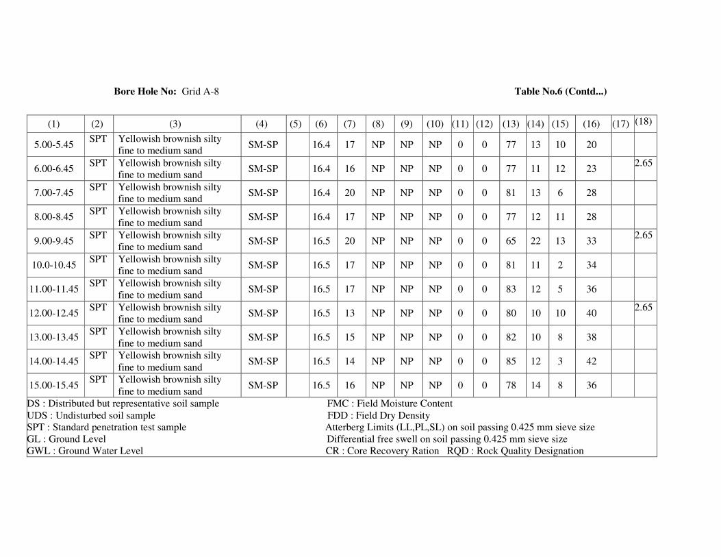
Bore Hole No: Grid A-8 Table No.6 (Contd...)
(1) (2) (3) (4) (5) (6) (7) (8) (9) (10) (11) (12) (13) (14) (15) (16) (17) (18)
5.00-5.45 SPT Yellowish brownish silty
fine to medium sand SM-SP 16.4 17 NP NP NP 0 0 77 13 10 20
6.00-6.45 SPT Yellowish brownish silty
fine to medium sand SM-SP 16.4 16 NP NP NP 0 0 77 11 12 23
2.65
7.00-7.45 SPT Yellowish brownish silty
fine to medium sand SM-SP 16.4 20 NP NP NP 0 0 81 13 6 28
8.00-8.45 SPT Yellowish brownish silty
fine to medium sand SM-SP 16.4 17 NP NP NP 0 0 77 12 11 28
9.00-9.45 SPT Yellowish brownish silty
fine to medium sand SM-SP 16.5 20 NP NP NP 0 0 65 22 13 33
2.65
10.0-10.45 SPT Yellowish brownish silty
fine to medium sand SM-SP 16.5 17 NP NP NP 0 0 81 11 2 34
11.00-11.45 SPT Yellowish brownish silty
fine to medium sand SM-SP 16.5 17 NP NP NP 0 0 83 12 5 36
12.00-12.45 SPT Yellowish brownish silty
fine to medium sand SM-SP 16.5 13 NP NP NP 0 0 80 10 10 40
2.65
13.00-13.45 SPT Yellowish brownish silty
fine to medium sand SM-SP 16.5 15 NP NP NP 0 0 82 10 8 38
14.00-14.45 SPT Yellowish brownish silty
fine to medium sand SM-SP 16.5 14 NP NP NP 0 0 85 12 3 42
15.00-15.45 SPT Yellowish brownish silty
fine to medium sand SM-SP 16.5 16 NP NP NP 0 0 78 14 8 36
DS : Distributed but representative soil sample FMC : Field Moisture Content
UDS : Undisturbed soil sample FDD : Field Dry Density
SPT : Standard penetration test sample Atterberg Limits (LL,PL,SL) on soil passing 0.425 mm sieve size
GL : Ground Level Differential free swell on soil passing 0.425 mm sieve size
GWL : Ground Water Level CR : Core Recovery Ration RQD : Rock Quality Designation

GEOTECHNICAL LABORATORY: CIVIL ENGINEERING DEPARTMENT V.R. SIDDHARTHA ENGINEERING COLLEGE:: VIJAYAWADA – 7
TABLE: 7 Idealized Design Soil Parameters
Project: Soil Investigation for AP Capital City Seed Area of 16 Sq. KM - The Commissioner /APCRDA/ Vijayawada
Location: A.P. Capital City Seed Area - Guntur District BORE HOLE NO.: Grid – B - 6
Andhra Pradesh (Grid – “B” Line)
Reduced level of the Bore hole = Depth of Water level: 2.50m Depth below
the existing
ground level
(metres)
Visual Identification of soil I.S. Soil
Classification
Natural
Moisture
Content
(%)
Dry
Unit
Weight [KN/m3]
Recorded
SPT value
(N)
Un confined
Compressive
Strength [KN/m2]
Shear Parameters Safe bearing
Capacity
[KN/m2] Cohesion C
[KN/m2] φ
(deg)
0.00-2.50 Brownish plastic silty clay MH-CH 26 15.50 UDS,6 58 29 0 60
2.50-5.00 Brownish plastic silty clay MH-CH 28,25 15.2
15.4 UDS,8 78,82 39,41 0 80
5.00-7.00 Yellowish brownish fine to
medium sand SP 18 16.20 14,17
[Es = 500
kg/cm2] 0 33 175
7.00-11.00 Yellowish brownish fine to
medium sand SP 19 16.30
22,25,29
33
[Es = 550
kg/cm2] 0 34 200
11.00-16.00 Yellowish brownish fine to
medium sand + pebbles SP 15 16.40
37,41,
38,42,46
[Es = 600
kg/cm2] 0 36 225
16.00-18.70 Yellowish brownish fine to
medium sand + pebbles SP 12 16.30
39,32
33
[Es = 550
kg/cm2] 0 34 200
18.70-21.00 Blackish plastic silty clay MH-CH 40 14.50 UDS,22 186 93 0 190
21.00-23.00 Blackish plastic silty clay MH-CH 38 14.60 UDS,28 268 134 0 270
23.00-25.00 Blackish plastic silty clay MH-CH 38 14.70 UDS,24 240 120 - 240
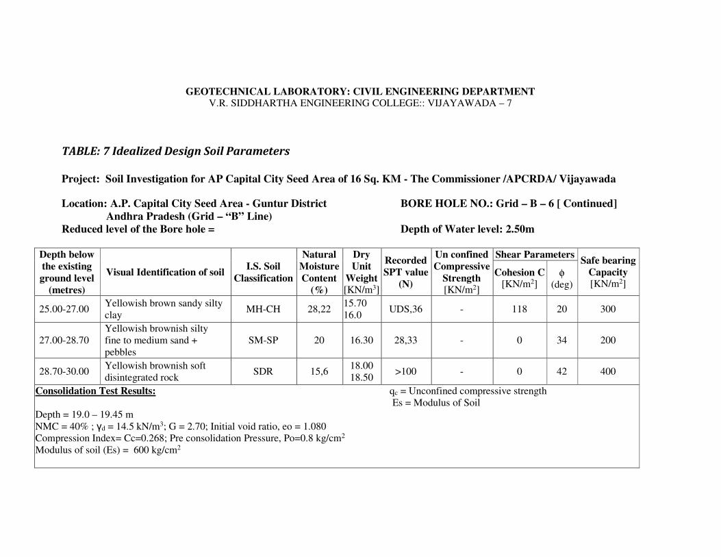
GEOTECHNICAL LABORATORY: CIVIL ENGINEERING DEPARTMENT V.R. SIDDHARTHA ENGINEERING COLLEGE:: VIJAYAWADA – 7
TABLE: 7 Idealized Design Soil Parameters
Project: Soil Investigation for AP Capital City Seed Area of 16 Sq. KM - The Commissioner /APCRDA/ Vijayawada
Location: A.P. Capital City Seed Area - Guntur District BORE HOLE NO.: Grid – B – 6 [ Continued]
Andhra Pradesh (Grid – “B” Line)
Reduced level of the Bore hole = Depth of Water level: 2.50m
Depth below
the existing
ground level
(metres)
Visual Identification of soil I.S. Soil
Classification
Natural
Moisture
Content
(%)
Dry
Unit
Weight [KN/m3]
Recorded
SPT value
(N)
Un confined
Compressive
Strength [KN/m2]
Shear Parameters Safe bearing
Capacity [KN/m2]
Cohesion C [KN/m2]
φ (deg)
25.00-27.00 Yellowish brown sandy silty
clay MH-CH 28,22
15.70
16.0 UDS,36 - 118 20 300
27.00-28.70
Yellowish brownish silty
fine to medium sand +
pebbles
SM-SP 20 16.30 28,33 - 0 34 200
28.70-30.00 Yellowish brownish soft
disintegrated rock SDR 15,6
18.00
18.50 >100 - 0 42 400
Consolidation Test Results: qc = Unconfined compressive strength
Es = Modulus of Soil
Depth = 19.0 – 19.45 m
NMC = 40% ; γd = 14.5 kN/m3; G = 2.70; Initial void ratio, eo = 1.080
Compression Index= Cc=0.268; Pre consolidation Pressure, Po=0.8 kg/cm2
Modulus of soil (Es) = 600 kg/cm2

GEOTECHNICAL LABORATORY: CIVIL ENGINEERING DEPARTMENT
V.R. SIDDHARTHA ENGINEERING COLLEGE:: VIJAYAWADA – 7
TABLE No: 8 Results of Laboratory Soil Testing
Project: Soil Investigation for AP Capital City Seed Area of 16 Sq. KM - The Commissioner /APCRDA/ Vijayawada
Location: A.P. Capital City Seed Area - Guntur District BORE HOLE NO.: Grid – B - 6
Andhra Pradesh (Grid – “B” Line)
Date Depth of GWT below GL: 2.50 m
Dep
th b
elow
GL
(m
)
Type
of
Sam
ple
Vis
ual
Identi
fica
tion o
f
Soil
I.S
. S
oil
Cla
ssif
icat
ion
Unco
nfi
ned
com
pre
ssiv
e
Str
ength
qu [
KN
.M2]
Dry
unit
Wei
ght,
γd [
KN
.M3]
Nat
ura
l M
ois
ture
Conte
nt
(%)
Liq
uid
Lim
it (
%)
Pla
stic
Lim
it (
%)
Pla
stic
ity I
ndex
Gra
vel
Siz
e (%
)
Coars
e S
and s
ize
(%)
Mediu
m S
and S
ize
(%)
Fin
e S
and s
ize
(%)
Sli
t and c
lay s
ize
(%)
Rec
ord
ed S
PT
Val
ue,
(N
)
Dif
fere
nti
al F
ree
swel
l
Index
(%)
Speci
fic
Gra
vit
y , G
(1) (2) (3) (4) (5) (6) (7) (8) (9) (10) (11) (12) (13) (14) (15) (16) (17) (18)
1.00-1.45 UDS Brownish plastic silty clay MH-CH 58 15.5 26 58 26 32
1.50-1.95 SPT Brownish plastic silty clay MH-CH 25 0 0 0 2 98 6 40
2.00-2.95 UDS Brownish plastic silty clay MH-CH 78 15.2 28
3.00-3.45 SPT Brownish plastic silty clay MH-CH 24 768 28 40 8
4.00-4.45 UDS Brownish plastic silty clay MH-CH 82 15.4 25 0 0 0 2 98 80
4.50-4.95 SPT Brownish plastic silty clay MH-CH 25 70 30 40 8
5.00-5.45 SPT Yellowish brownish fine to
medium sand SP 16.2 18 NP NP NP 0 2 85 10 3 14
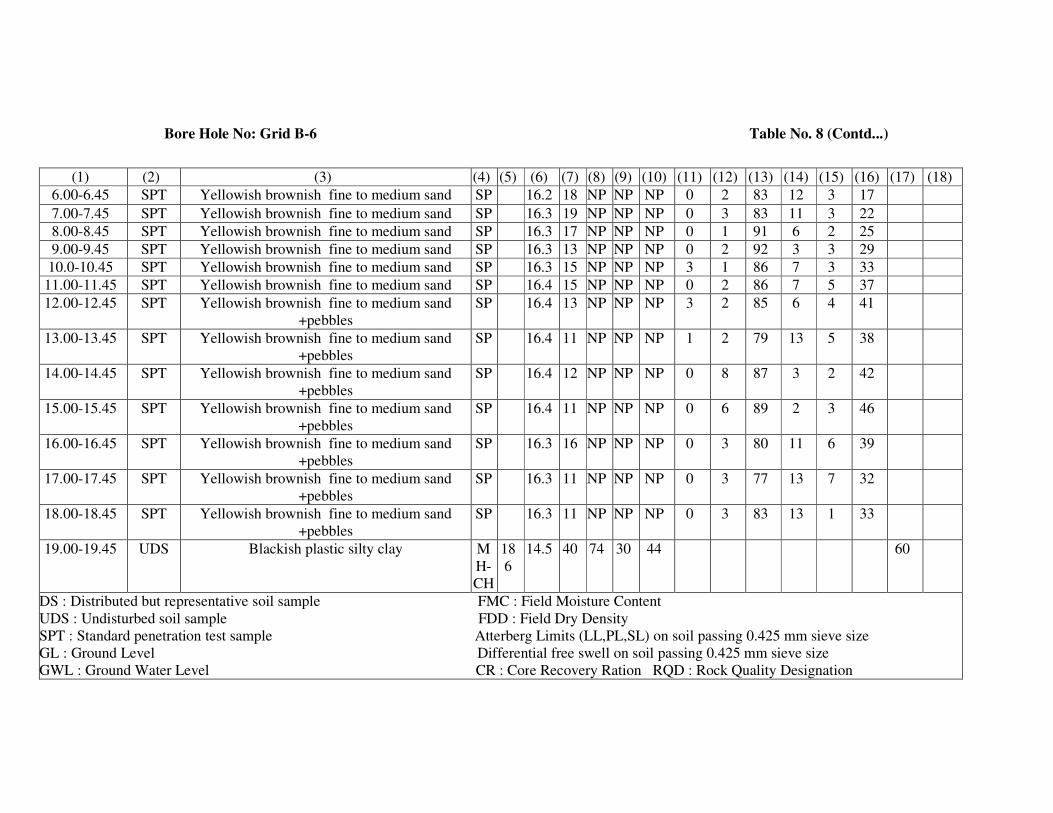
Bore Hole No: Grid B-6 Table No. 8 (Contd...)
(1) (2) (3) (4) (5) (6) (7) (8) (9) (10) (11) (12) (13) (14) (15) (16) (17) (18)
6.00-6.45 SPT Yellowish brownish fine to medium sand SP 16.2 18 NP NP NP 0 2 83 12 3 17
7.00-7.45 SPT Yellowish brownish fine to medium sand SP 16.3 19 NP NP NP 0 3 83 11 3 22
8.00-8.45 SPT Yellowish brownish fine to medium sand SP 16.3 17 NP NP NP 0 1 91 6 2 25
9.00-9.45 SPT Yellowish brownish fine to medium sand SP 16.3 13 NP NP NP 0 2 92 3 3 29
10.0-10.45 SPT Yellowish brownish fine to medium sand SP 16.3 15 NP NP NP 3 1 86 7 3 33
11.00-11.45 SPT Yellowish brownish fine to medium sand SP 16.4 15 NP NP NP 0 2 86 7 5 37
12.00-12.45 SPT Yellowish brownish fine to medium sand
+pebbles
SP 16.4 13 NP NP NP 3 2 85 6 4 41
13.00-13.45 SPT Yellowish brownish fine to medium sand
+pebbles
SP 16.4 11 NP NP NP 1 2 79 13 5 38
14.00-14.45 SPT Yellowish brownish fine to medium sand
+pebbles
SP 16.4 12 NP NP NP 0 8 87 3 2 42
15.00-15.45 SPT Yellowish brownish fine to medium sand
+pebbles
SP 16.4 11 NP NP NP 0 6 89 2 3 46
16.00-16.45 SPT Yellowish brownish fine to medium sand
+pebbles
SP 16.3 16 NP NP NP 0 3 80 11 6 39
17.00-17.45 SPT Yellowish brownish fine to medium sand
+pebbles
SP 16.3 11 NP NP NP 0 3 77 13 7 32
18.00-18.45 SPT Yellowish brownish fine to medium sand
+pebbles
SP 16.3 11 NP NP NP 0 3 83 13 1 33
19.00-19.45 UDS Blackish plastic silty clay M
H-
CH
18
6
14.5 40 74 30 44 60
DS : Distributed but representative soil sample FMC : Field Moisture Content
UDS : Undisturbed soil sample FDD : Field Dry Density
SPT : Standard penetration test sample Atterberg Limits (LL,PL,SL) on soil passing 0.425 mm sieve size
GL : Ground Level Differential free swell on soil passing 0.425 mm sieve size
GWL : Ground Water Level CR : Core Recovery Ration RQD : Rock Quality Designation
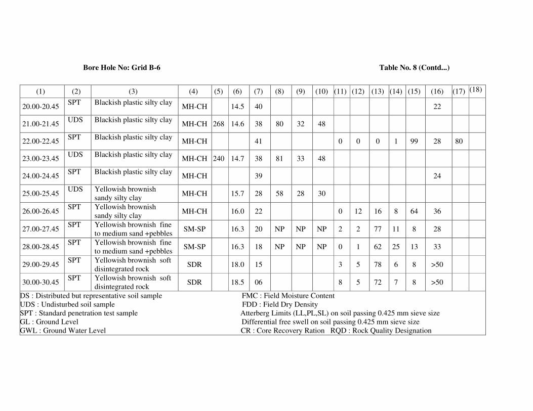
Bore Hole No: Grid B-6 Table No. 8 (Contd...)
(1) (2) (3) (4) (5) (6) (7) (8) (9) (10) (11) (12) (13) (14) (15) (16) (17) (18)
20.00-20.45 SPT Blackish plastic silty clay
MH-CH 14.5 40 22
21.00-21.45 UDS Blackish plastic silty clay
MH-CH 268 14.6 38 80 32 48
22.00-22.45 SPT Blackish plastic silty clay
MH-CH 41 0 0 0 1 99 28 80
23.00-23.45 UDS Blackish plastic silty clay
MH-CH 240 14.7 38 81 33 48
24.00-24.45 SPT Blackish plastic silty clay
MH-CH 39 24
25.00-25.45 UDS Yellowish brownish
sandy silty clay MH-CH 15.7 28 58 28 30
26.00-26.45 SPT Yellowish brownish
sandy silty clay MH-CH 16.0 22 0 12 16 8 64 36
27.00-27.45 SPT Yellowish brownish fine
to medium sand +pebbles SM-SP 16.3 20 NP NP NP 2 2 77 11 8 28
28.00-28.45 SPT Yellowish brownish fine
to medium sand +pebbles SM-SP 16.3 18 NP NP NP 0 1 62 25 13 33
29.00-29.45 SPT Yellowish brownish soft
disintegrated rock SDR 18.0 15 3 5 78 6 8 >50
30.00-30.45 SPT Yellowish brownish soft
disintegrated rock SDR 18.5 06 8 5 72 7 8 >50
DS : Distributed but representative soil sample FMC : Field Moisture Content
UDS : Undisturbed soil sample FDD : Field Dry Density
SPT : Standard penetration test sample Atterberg Limits (LL,PL,SL) on soil passing 0.425 mm sieve size
GL : Ground Level Differential free swell on soil passing 0.425 mm sieve size
GWL : Ground Water Level CR : Core Recovery Ration RQD : Rock Quality Designation
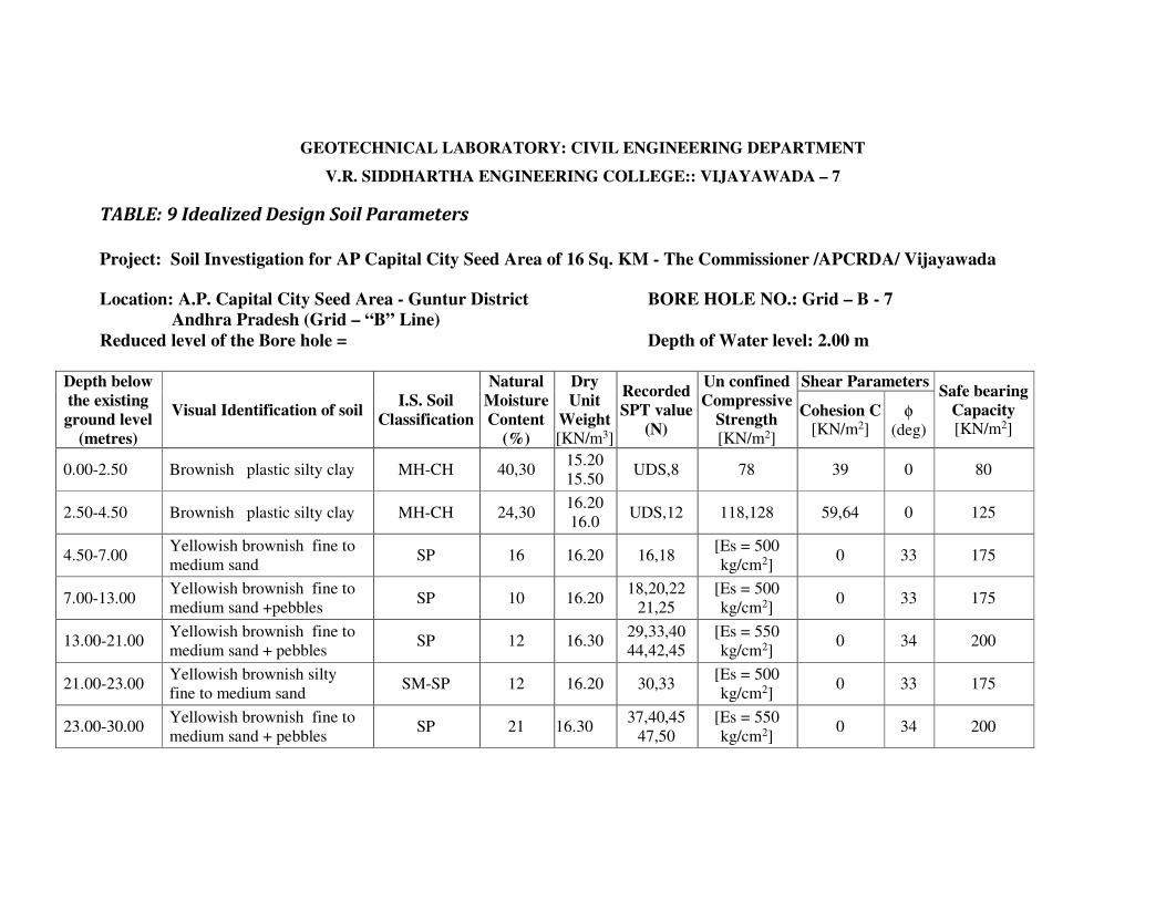
GEOTECHNICAL LABORATORY: CIVIL ENGINEERING DEPARTMENT
V.R. SIDDHARTHA ENGINEERING COLLEGE:: VIJAYAWADA – 7
TABLE: 9 Idealized Design Soil Parameters
Project: Soil Investigation for AP Capital City Seed Area of 16 Sq. KM - The Commissioner /APCRDA/ Vijayawada
Location: A.P. Capital City Seed Area - Guntur District BORE HOLE NO.: Grid – B - 7
Andhra Pradesh (Grid – “B” Line)
Reduced level of the Bore hole = Depth of Water level: 2.00 m
Depth below
the existing
ground level
(metres)
Visual Identification of soil I.S. Soil
Classification
Natural
Moisture
Content
(%)
Dry
Unit
Weight
[KN/m3]
Recorded
SPT value
(N)
Un confined
Compressive
Strength
[KN/m2]
Shear Parameters Safe bearing
Capacity [KN/m2]
Cohesion C [KN/m2]
φ (deg)
0.00-2.50 Brownish plastic silty clay MH-CH 40,30 15.20
15.50 UDS,8 78 39 0 80
2.50-4.50 Brownish plastic silty clay MH-CH 24,30 16.20
16.0 UDS,12 118,128 59,64 0 125
4.50-7.00 Yellowish brownish fine to
medium sand SP 16 16.20 16,18
[Es = 500
kg/cm2] 0 33 175
7.00-13.00 Yellowish brownish fine to
medium sand +pebbles SP 10 16.20
18,20,22
21,25
[Es = 500
kg/cm2] 0 33 175
13.00-21.00 Yellowish brownish fine to
medium sand + pebbles SP 12 16.30
29,33,40
44,42,45
[Es = 550
kg/cm2] 0 34 200
21.00-23.00 Yellowish brownish silty
fine to medium sand SM-SP 12 16.20 30,33
[Es = 500
kg/cm2] 0 33 175
23.00-30.00 Yellowish brownish fine to
medium sand + pebbles SP 21 16.30
37,40,45
47,50
[Es = 550
kg/cm2] 0 34 200

GEOTECHNICAL LABORATORY: CIVIL ENGINEERING DEPARTMENT
V.R. SIDDHARTHA ENGINEERING COLLEGE:: VIJAYAWADA – 7
TABLE No: 10 Results of Laboratory Soil Testing
Project: Soil Investigation for AP Capital City Seed Area of 16 Sq. KM - The Commissioner /APCRDA/ Vijayawada
Location: A.P. Capital City Seed Area - Guntur District BORE HOLE NO.: Grid – B - 7
Andhra Pradesh (Grid – “B” Line)
Date Depth of GWT below GL: 2.00 metres
Dep
th b
elow
GL
(m
)
Type
of
Sam
ple
Vis
ual
Identi
fica
tion o
f
Soil
I.S
. S
oil
Cla
ssif
icat
ion
Unco
nfi
ned
com
pre
ssiv
e
Str
ength
qu [
KN
.M2]
Dry
unit
Wei
ght,
γd [
KN
.M3]
Nat
ura
l M
ois
ture
Conte
nt
(%)
Liq
uid
Lim
it (
%)
Pla
stic
Lim
it (
%)
Pla
stic
ity I
ndex
Gra
vel
Siz
e (%
)
Coars
e S
and s
ize
(%)
Mediu
m S
and S
ize
(%)
Fin
e S
and s
ize
(%)
Sli
t and c
lay s
ize
(%)
Rec
ord
ed S
PT
Val
ue,
(N
)
Dif
fere
nti
al F
ree
swel
l
Index
(%)
Speci
fic
Gra
vit
y , G
(1) (2) (3) (4) (5) (6) (7) (8) (9) (10) (11) (12) (13) (14) (15) (16) (17) (18)
1.00-1.45 UDS Brownish plastic silty clay MH-CH 78 15.2 40 70 30 40
1.50-1.95 SPT Brownish plastic silty clay MH-CH 15.5 30 0 0 0 2 98 8 40
2.00-2.95 UDS Brownish plastic silty clay MH-CH 118 16.2 24 72 28 44
3.00-3.45 SPT Brownish plastic silty clay MH-CH 30 0 0 0 2 98 12
4.00-4.45 UDS Brownish plastic silty clay MH-CH 128 16.0 30 70 30 40
5.00-5.45 SPT Yellowish brownish fine to
medium sand SP 16.2 18 NP NP NP 0 2 85 10 3 14
6.00-6.45 SPT Yellowish brownish fine to
medium sand SP 16.2 10 NP NP NP 0 3 87 4 6 18
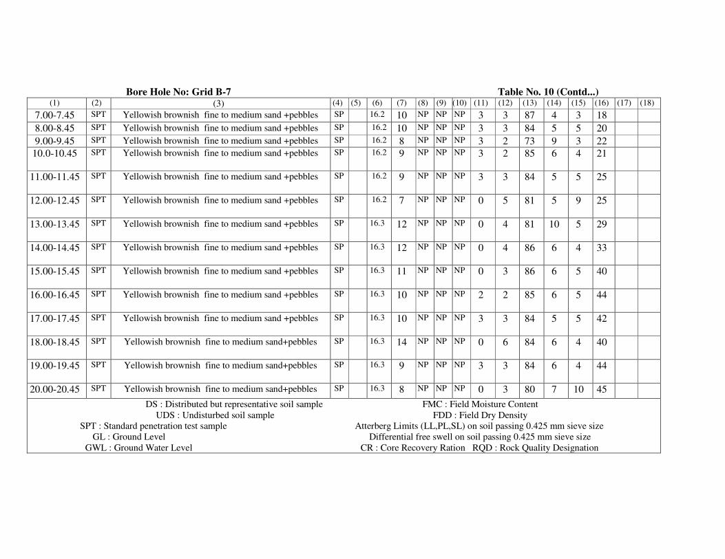
Bore Hole No: Grid B-7 Table No. 10 (Contd...) (1) (2) (3) (4) (5) (6) (7) (8) (9) (10) (11) (12) (13) (14) (15) (16) (17) (18)
7.00-7.45 SPT Yellowish brownish fine to medium sand +pebbles SP 16.2 10 NP NP NP 3 3 87 4 3 18
8.00-8.45 SPT Yellowish brownish fine to medium sand +pebbles SP 16.2 10 NP NP NP 3 3 84 5 5 20
9.00-9.45 SPT Yellowish brownish fine to medium sand +pebbles SP 16.2 8 NP NP NP 3 2 73 9 3 22
10.0-10.45 SPT Yellowish brownish fine to medium sand +pebbles SP 16.2 9 NP NP NP 3 2 85 6 4 21
11.00-11.45 SPT Yellowish brownish fine to medium sand +pebbles SP 16.2 9 NP NP NP 3 3 84 5 5 25
12.00-12.45 SPT Yellowish brownish fine to medium sand +pebbles SP 16.2 7 NP NP NP 0 5 81 5 9 25
13.00-13.45 SPT Yellowish brownish fine to medium sand +pebbles SP 16.3 12 NP NP NP 0 4 81 10 5 29
14.00-14.45 SPT Yellowish brownish fine to medium sand +pebbles SP 16.3 12 NP NP NP 0 4 86 6 4 33
15.00-15.45 SPT Yellowish brownish fine to medium sand +pebbles SP 16.3 11 NP NP NP 0 3 86 6 5 40
16.00-16.45 SPT Yellowish brownish fine to medium sand +pebbles SP 16.3 10 NP NP NP 2 2 85 6 5 44
17.00-17.45 SPT Yellowish brownish fine to medium sand +pebbles SP 16.3 10 NP NP NP 3 3 84 5 5 42
18.00-18.45 SPT Yellowish brownish fine to medium sand+pebbles SP 16.3 14 NP NP NP 0 6 84 6 4 40
19.00-19.45 SPT Yellowish brownish fine to medium sand+pebbles SP 16.3 9 NP NP NP 3 3 84 6 4 44
20.00-20.45 SPT Yellowish brownish fine to medium sand+pebbles SP 16.3 8 NP NP NP 0 3 80 7 10 45
DS : Distributed but representative soil sample FMC : Field Moisture Content
UDS : Undisturbed soil sample FDD : Field Dry Density
SPT : Standard penetration test sample Atterberg Limits (LL,PL,SL) on soil passing 0.425 mm sieve size
GL : Ground Level Differential free swell on soil passing 0.425 mm sieve size
GWL : Ground Water Level CR : Core Recovery Ration RQD : Rock Quality Designation

Bore Hole No: Grid B-7 Table No. 10 (Contd...)
(1) (2) (3) (4) (5) (6) (7) (8) (9) (10) (11) (12) (13) (14) (15) (16) (17) (18)
21.00-21.45 SPT Yellowish brownish silty
fine to medium sand SM-SP 16.2 7 NP NP NP 0 2 75 12 16 30
22.00-22.45 SPT Yellowish brownish silty
fine to medium sand SM-SP 16.2 12 NP NP NP 0 2 73 15 13 33
23.00-23.45 SPT Yellowish brownish fine
to medium sand
SP 16.3 19 NP NP NP 0 2 90 7 1 37
24.00-24.45 SPT Yellowish brownish fine
to medium sand
SP 16.3 9 NP NP NP 0 2 82 10 6 40
25.00-25.45 SPT Yellowish brownish fine
to medium sand
SP 16.3 20 NP NP NP 0 1 87 10 2 41
26.00-26.45 SPT Yellowish brownish fine
to medium sand
SP 16.3 21 NP NP NP 0 2 87 10 1 45
27.00-27.45 SPT Yellowish brownish fine
to medium sand
SP 16.3 21 NP NP NP 0 2 89 7 2 45
28.00-28.45 SPT Yellowish brownish fine
to medium sand
SP 16.3 21 NP NP NP 0 1 88 8 3 47
29.00-29.45 SPT Yellowish brownish fine
to medium sand
SP 16.3 21 NP NP NP 0 1 88 9 2 50
30.00-30.45 SPT Yellowish brownish fine
to medium sand
SP 16.3 20 NP NP NP 0 2 86 10 2 50
DS : Distributed but representative soil sample FMC : Field Moisture Content
UDS : Undisturbed soil sample FDD : Field Dry Density
SPT : Standard penetration test sample Atterberg Limits (LL,PL,SL) on soil passing 0.425 mm sieve size
GL : Ground Level Differential free swell on soil passing 0.425 mm sieve size
GWL : Ground Water Level CR : Core Recovery Ration RQD : Rock Quality Designation

GEOTECHNICAL LABORATORY: CIVIL ENGINEERING DEPARTMENT V.R. SIDDHARTHA ENGINEERING COLLEGE:: VIJAYAWADA – 7
TABLE: 11 Idealized Design Soil Parameters
Project: Soil Investigation for AP Capital City Seed Area of 16 Sq. KM - The Commissioner /APCRDA/ Vijayawada
Location: A.P. Capital City Seed Area - Guntur District BORE HOLE NO.: Grid – B - 8
Andhra Pradesh (Grid – “B” Line)
Reduced level of the Bore hole = Depth of Water level: 2.00 m
Depth below
the existing
ground level
(metres)
Visual Identification of soil I.S. Soil
Classification
Natural
Moisture
Content
(%)
Dry
Unit
Weight [KN/m3]
Recorded
SPT value
(N)
Un confined
Compressive
Strength [KN/m2]
Shear Parameters Safe bearing
Capacity
[KN/m2] Cohesion C
[KN/m2] φ
(deg)
0.00-2.50 Brownish plastic silty clay MH-CH 24,27 16.00
15.80 UDS,6 58 25 4 60
2.50-4.00 Brownish plastic silty clay MH-CH 23,26 16.00
15.90 UDS,9 86 40 4 90
4.00-5.00 Brownish plastic silty MH-CH 23,28 16.10
15.70 UDS,12 118 56 4 120
5.00-10.00 Yellowish brownish fine to
medium sand SP 14,17 16.20
18,16
19,22,24
[Es = 550
kg/cm2] 0 34 200
10.00-15.50 Yellowish brownish silty
fine to medium sand SM-SP 18,21 16.30
28,31,35
36,41,38
[Es = 550
kg/cm2] 0 36 225

GEOTECHNICAL LABORATORY: CIVIL ENGINEERING DEPARTMENT
V.R. SIDDHARTHA ENGINEERING COLLEGE:: VIJAYAWADA – 7
TABLE No: 12 Results of Laboratory Soil Testing
Project: Soil Investigation for AP Capital City Seed Area of 16 Sq. KM - The Commissioner /APCRDA/ Vijayawada
Location: A.P. Capital City Seed Area - Guntur District BORE HOLE NO.: Grid – B - 8
Andhra Pradesh (Grid – “B” Line)
Date Depth of GWT below GL: 2.00 m
Depth
bel
ow
GL
(m
)
Type
of
Sam
ple
Vis
ual
Identi
fica
tion o
f
Soil
I.S
. S
oil
Cla
ssif
icati
on
Unco
nfi
ned
com
pre
ssiv
e
Str
ength
qu [
KN
.M2]
Dry
unit
Wei
ght,
γd [
KN
.M3]
Nat
ura
l M
ois
ture
Conte
nt
(%)
Liq
uid
Lim
it (
%)
Pla
stic
Lim
it (
%)
Pla
stic
ity I
ndex
Gra
vel
Siz
e (%
)
Coar
se S
and s
ize
(%)
Mediu
m S
and S
ize
(%)
Fin
e S
and s
ize
(%)
Sli
t and c
lay s
ize
(%)
Rec
ord
ed S
PT
Val
ue,
(N
)
Dif
fere
nti
al F
ree
swel
l
Index
(%)
Speci
fic
Gra
vit
y , G
(1) (2) (3) (4) (5) (6) (7) (8) (9) (10) (11) (12) (13) (14) (15) (16) (17) (18)
1.00-1.45 UDS Brownish plastic silty clay MH-CH 58 16.0 24 60 26 34
1.50-1.95 SPT Brownish plastic silty clay MH-CH 15.8 27 0 0 0 1 99 6 50 2.68
2.50-2.95 UDS Brownish plastic silty clay MH-CH 86 16.0 23 64 26 38
3.00-3.45 SPT Brownish plastic silty clay MH-CH 15.9 26 0 0 0 2 98 9 60 2.68
4.00-4.45 UDS Brownish plastic silty clay MH-CH 118 16.1 23 62 25 37
4.50-4.95 SPT Brownish plastic silty clay MH-CH 15.7 28 58 27 31 0 0 0 2 98 12 70
5.00-5.45 SPT Yellowish brownish fine to
medium sand SP 16.2 14 NP NP NP 0 01 86 11 2 18

Bore Hole No: Grid B-8 Table No. 12 (Contd...)
(1) (2) (3) (4) (5) (6) (7) (8) (9) (10) (11) (12) (13) (14) (15) (16) (17) (18)
6.00-6.45 SPT Yellowish brownish fine
to medium sand SP 16.2 14 NP NP NP 0 3 80 14 3 16
7.00-7.45 SPT Yellowish brownish fine
to medium sand SP
16.2 17 NP NP NP
0 3 68 25 4 19
8.00-8.45 SPT Yellowish brownish fine
to medium sand SP
16.2 15 NP NP NP
0 1 80 17 2 22
9.00-9.45 SPT Yellowish brownish fine
to medium sand SP
16.2 16 NP NP NP
0 4 76 15 5 24
10.0-10.45 SPT Yellowish brownish silty
fine to medium sand SM-SP 16.3 18 NP NP NP
0 3 75 15 7 28
11.00-11.45 SPT Yellowish brownish silty
fine to medium sand SM-SP 16.3 13 NP NP NP
0 3 88 6 3 31
12.00-12.45 SPT Yellowish brownish silty
fine to medium sand SM-SP 16.3 14 NP NP NP
0 2 89 6 3 35
13.00-13.45 SPT Yellowish brownish silty
fine to medium sand SM-SP 16.3 16 NP NP NP
0 3 83 11 3 36
14.00-14.45 SPT Yellowish brownish silty
fine to medium sand SM-SP 16.3 15 NP NP NP
0 2 75 13 10 41
15.00-15.45 SPT Yellowish brownish silty
fine to medium sand SM-SP 16.3 21 NP NP NP
0 2 88 6 4 38
DS : Distributed but representative soil sample FMC : Field Moisture Content
UDS : Undisturbed soil sample FDD : Field Dry Density
SPT : Standard penetration test sample Atterberg Limits (LL,PL,SL) on soil passing 0.425 mm sieve size
GL : Ground Level Differential free swell on soil passing 0.425 mm sieve size
GWL : Ground Water Level CR : Core Recovery Ration RQD : Rock Quality Designation

GEOTECHNICAL LABORATORY: CIVIL ENGINEERING DEPARTMENT V.R. SIDDHARTHA ENGINEERING COLLEGE:: VIJAYAWADA – 7
TABLE: 13 Idealized Design Soil Parameters
Project: Soil Investigation for AP Capital City Seed Area of 16 Sq. KM - The Commissioner /APCRDA/ Vijayawada
Location: A.P. Capital City Seed Area - Guntur District BORE HOLE NO.: Grid – C - 6
Andhra Pradesh (Grid – “C” Line)
Reduced level of the Bore hole = Depth of Water level: 2.80 m
Depth below
the existing
ground level
(metres)
Visual Identification of soil
I.S. Soil
Classificati
on
Natural
Moisture
Content
(%)
Dry
Unit
Weight [KN/m3]
Recorded
SPT value
(N)
Un confined
Compressive
Strength [KN/m2]
Shear Parameters Safe bearing
Capacity [KN/m2]
Cohesion C [KN/m2]
φ (deg)
0.00-1.50 Brownish plastic silty clay MH-CH 27 15.50 UDS 46 23 0 50
1.50-3.00 Brownish plastic silty clay MH-CH 29,26 15.60 UDS,10 108 54 0 110
3.00-4.10 Yellowish brownish silty fine to
medium sand SM-SP 20 16.30 16 - 0 33 175
4.10-5.00 Yellowish brownish plastic silty
clay MH-CH 24 16.10 UDS,13 126 63 0 130
5.00-6.50 Yellowish brownish plastic silty
clay MH-CH 22 16.20 UDS,17 164 82 0 170
6.50-8.00 Yellowish brownish silty fine to
medium sand SM-SP 20 16.3 18 [Es = 500
kg/cm2] 0 33 175
8.00-12.50 Yellowish brownish silty fine to
medium sand SM-SP 21 16.40 26,32
36,39,44
[Es = 600
kg/cm2] 0 36 225
12.50-14.60 Blackish brown plastic silty clay MH-CH 36 14.20 UDS,14 142 71 0 140
14.60-15.50 Yellowish brownish fine to
medium sand SP 14 16.30 35 - 0 34 200

GEOTECHNICAL LABORATORY: CIVIL ENGINEERING DEPARTMENT
V.R. SIDDHARTHA ENGINEERING COLLEGE:: VIJAYAWADA – 7
TABLE No: 14 Results of Laboratory Soil Testing
Project: Soil Investigation for AP Capital City Seed Area of 16 Sq. KM - The Commissioner /APCRDA/ Vijayawada
Location: A.P. Capital City Seed Area - Guntur District BORE HOLE NO.: Grid – C - 6
Andhra Pradesh (Grid – “C” Line)
Date Depth of GWT below GL: 2.80 m
Dep
th b
elow
GL
(m
)
Type
of
Sam
ple
Vis
ual
Iden
tifi
cati
on o
f
Soil
I.S
. S
oil
Cla
ssif
icat
ion
Unconfi
ned
com
pre
ssiv
e
Str
ength
qu [
KN
.M2]
Dry
unit
Weig
ht,
γd
[KN
.M3]
Natu
ral
Mois
ture
Conte
nt
(%)
Liq
uid
Lim
it (
%)
Pla
stic
Lim
it (
%)
Pla
stic
ity I
ndex
Gra
vel
Siz
e (%
)
Coars
e S
and s
ize
(%)
Mediu
m S
and S
ize
(%)
Fin
e S
and s
ize
(%)
Sli
t an
d c
lay s
ize
(%)
Rec
ord
ed S
PT
Val
ue,
(N
)
Dif
fere
nti
al F
ree
swel
l
Index
(%)
Spec
ific
Gra
vit
y , G
(1) (2) (3) (4) (5) (6) (7) (8) (9) (10) (11) (12) (13) (14) (15) (16) (17) (18)
1.00-1.45 UDS Brownish plastic silty clay MH-CH 46 15.5 27 68 28 40 60 2.68
1.50-1.95 SPT Brownish plastic silty clay MH-CH 15.4 29 0 0 0 2 98 10
2.50-2.95 UDS Brownish plastic silty clay MH-CH 108 15.6 26 54 26 28 60 2.68
3.00-3.45 SPT Yellowish brownish silty fine
to medium sand SM-SP 16.3 20 NP NP NP 0 0 23 56 21 16
2.65
4.00-4.45 UDS Yellowish brownish plastic
silty clay MH-CH 126 16.1 24 59 27 32 60
4.50-4.95 SPT Yellowish brownish plastic
silty clay MH-CH 16.1 24 0 0 0 2 98 13
2.67
5.50-5.95 UDS Yellowish brownish plastic
silty clay MH-CH 164 16.2 22 56 26 30

Bore Hole No: Grid, C-6 Table No. 14 (Contd...)
(1) (2) (3) (4) (5) (6) (7) (8) (9) (10) (11) (12) (13) (14) (15) (16) (17) (18)
6.00-6.45 SPT Yellowish brownish
plastic silty clay MH-CH 15.5 28 17
7.00-7.45 SPT Yellowish brownish silty
fine to medium sand SM-SP 16.3 20 NP NP NP 0 0 84 11 5 18
8.00-8.45 SPT Yellowish brownish silty
fine to medium sand SM-SP 16.4 21 NP NP NP 0 0 85 07 8 26
9.00-9.45 SPT Yellowish brownish silty
fine to medium sand SM-SP 16.4 22 NP NP NP 0 0 82 10 8 32
10.0-10.45 SPT Yellowish brownish
plastic silty clay SM-SP 16.4 14 NP NP NP 0 0 80 14 6 36
11.00-11.45 SPT Yellowish brownish
plastic silty clay SM-SP 16.4 15 NP NP NP 0 0 85 11 4 39
12.00-12.45 SPT Yellowish brownish silty
fine to medium sand SM-SP 16.4 14 NP NP NP 0 0 86 11 3 44
13.00-13.45 SPT Blackish brown plastic
silty clay MH-CH 14.2 36 95 32 63 14
14.00-14.45 UDS Blackish brown plastic
silty clay MH-CH 142 14.2 36 0 0 0 2 98 70
15.00-15.45 SPT Yellowish brownish fine
to medium sand SP 16.3 14 NP NP NP 0 0 87 9 4 35
DS : Distributed but representative soil sample FMC : Field Moisture Content
UDS : Undisturbed soil sample FDD : Field Dry Density
SPT : Standard penetration test sample Atterberg Limits (LL,PL,SL) on soil passing 0.425 mm sieve size
GL : Ground Level Differential free swell on soil passing 0.425 mm sieve size
GWL : Ground Water Level CR : Core Recovery Ration RQD : Rock Quality Designation
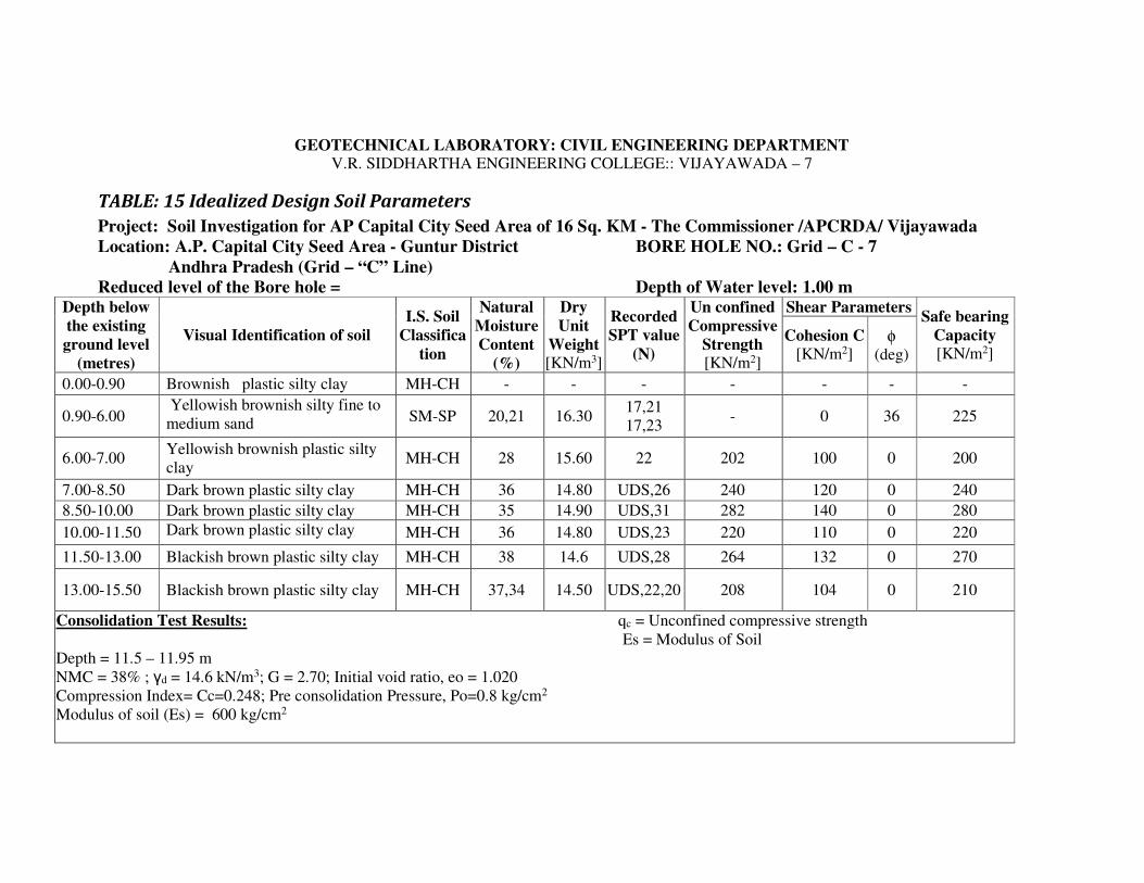
GEOTECHNICAL LABORATORY: CIVIL ENGINEERING DEPARTMENT V.R. SIDDHARTHA ENGINEERING COLLEGE:: VIJAYAWADA – 7
TABLE: 15 Idealized Design Soil Parameters
Project: Soil Investigation for AP Capital City Seed Area of 16 Sq. KM - The Commissioner /APCRDA/ Vijayawada
Location: A.P. Capital City Seed Area - Guntur District BORE HOLE NO.: Grid – C - 7
Andhra Pradesh (Grid – “C” Line)
Reduced level of the Bore hole = Depth of Water level: 1.00 m Depth below
the existing
ground level
(metres)
Visual Identification of soil
I.S. Soil
Classifica
tion
Natural
Moisture
Content
(%)
Dry
Unit
Weight [KN/m3]
Recorded
SPT value
(N)
Un confined
Compressive
Strength [KN/m2]
Shear Parameters Safe bearing
Capacity
[KN/m2] Cohesion C
[KN/m2] φ
(deg)
0.00-0.90 Brownish plastic silty clay MH-CH - - - - - - -
0.90-6.00 Yellowish brownish silty fine to
medium sand SM-SP 20,21 16.30
17,21
17,23 - 0 36 225
6.00-7.00 Yellowish brownish plastic silty
clay MH-CH 28 15.60 22 202 100 0 200
7.00-8.50 Dark brown plastic silty clay MH-CH 36 14.80 UDS,26 240 120 0 240
8.50-10.00 Dark brown plastic silty clay MH-CH 35 14.90 UDS,31 282 140 0 280
10.00-11.50 Dark brown plastic silty clay MH-CH 36 14.80 UDS,23 220 110 0 220
11.50-13.00 Blackish brown plastic silty clay MH-CH 38 14.6 UDS,28 264 132 0 270
13.00-15.50 Blackish brown plastic silty clay MH-CH 37,34 14.50 UDS,22,20 208 104 0 210
Consolidation Test Results: qc = Unconfined compressive strength
Es = Modulus of Soil
Depth = 11.5 – 11.95 m
NMC = 38% ; γd = 14.6 kN/m3; G = 2.70; Initial void ratio, eo = 1.020
Compression Index= Cc=0.248; Pre consolidation Pressure, Po=0.8 kg/cm2
Modulus of soil (Es) = 600 kg/cm2

GEOTECHNICAL LABORATORY: CIVIL ENGINEERING DEPARTMENT
V.R. SIDDHARTHA ENGINEERING COLLEGE:: VIJAYAWADA – 7
TABLE No: 16 Results of Laboratory Soil Testing
Project: Soil Investigation for AP Capital City Seed Area of 16 Sq. KM - The Commissioner /APCRDA/ Vijayawada
Location: A.P. Capital City Seed Area - Guntur District BORE HOLE NO.: Grid – C - 7
Andhra Pradesh (Grid – “C” Line)
Date Depth of GWT below GL: 1.00
Depth
bel
ow
GL
(m
)
Type
of
Sam
ple
Vis
ual
Identi
fica
tion o
f
Soil
I.S
. S
oil
Cla
ssif
icati
on
Unco
nfi
ned
com
pre
ssiv
e
Str
ength
qu [
KN
.M2]
Dry
unit
Wei
ght,
γd
[KN
.M3]
Nat
ura
l M
ois
ture
Conte
nt
(%)
Liq
uid
Lim
it (
%)
Pla
stic
Lim
it (
%)
Pla
stic
ity I
ndex
Gra
vel
Siz
e (%
)
Coar
se S
and s
ize
(%)
Med
ium
Sand S
ize
(%)
Fin
e S
and s
ize
(%)
Sli
t and c
lay s
ize
(%)
Rec
ord
ed S
PT
Val
ue,
(N
)
Dif
fere
nti
al F
ree
swel
l
Index
(%)
Speci
fic
Gra
vit
y , G
(1) (2) (3) (4) (5) (6) (7) (8) (9) (10) (11) (12) (13) (14) (15) (16) (17) (18)
1.00-1.45 DS Brownish plastic silty clay MH-CH
1.50-1.95 SPT Yellowish brownish silty
fine to medium sand SM-SP 16.3 20 NP NP NP 0 0 81 13 6 17
2.65
2.50-2.95 SPT Yellowish brownish silty
fine to medium sand SM-SP 16.3 19 NP NP NP 0 0 78 15 7 21
3.00-3.45 SPT Yellowish brownish silty
fine to medium sand SM-SP 16.3 13 NP NP NP 0 0 75 18 7 21
4.00-4.45 SPT Yellowish brownish silty
fine to medium sand SM-SP 16.3 18 NP NP NP 0 0 80 13 7 17
2.65
4.50-4.95 SPT Yellowish brownish silty
fine to medium sand SM-SP 16.3 21 NP NP NP 0 0 80 15 5 23
5.50-5.95 SPT Yellowish brownish plastic
silty clay MH-CH 202 15.6 28 68 28 40 22 60
2.70
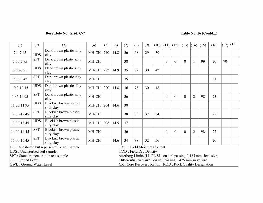
Bore Hole No: Grid, C-7 Table No. 16 (Contd...)
(1) (2) (3) (4) (5) (6) (7) (8) (9) (10) (11) (12) (13) (14) (15) (16) (17) (18)
7.0-7.45
UDS
Dark brown plastic silty
clay MH-CH 240 14.8 36 68 29 39
7.50-7.95 SPT Dark brown plastic silty
clay MH-CH 38 0 0 0 1 99 26 70
8.50-8.95 UDS Dark brown plastic silty
clay MH-CH 282 14.9 35 72 30 42
9.00-9.45 SPT Dark brown plastic silty
clay MH-CH 35 31
10.0-10.45 UDS Dark brown plastic silty
clay MH-CH 220 14.8 36 78 30 48
10.5-10.95 SPT Dark brown plastic silty
clay MH-CH 36 0 0 0 2 98 23
11.50-11.95 UDS Blackish brown plastic
silty clay MH-CH 264 14.6 38
12.00-12.45 SPT Blackish brown plastic
silty clay MH-CH 38 86 32 54 28
13.00-13.45 UDS Blackish brown plastic
silty clay MH-CH 208 14.5 37
14.00-14.45 SPT Blackish brown plastic
silty clay MH-CH 36 0 0 0 2 98 22
15.00-15.45 SPT Blackish brown plastic
silty clay MH-CH 14.6 34 88 32 56 20
DS : Distributed but representative soil sample FMC : Field Moisture Content
UDS : Undisturbed soil sample FDD : Field Dry Density
SPT : Standard penetration test sample Atterberg Limits (LL,PL,SL) on soil passing 0.425 mm sieve size
GL : Ground Level Differential free swell on soil passing 0.425 mm sieve size
GWL : Ground Water Level CR : Core Recovery Ration RQD : Rock Quality Designation

GEOTECHNICAL LABORATORY: CIVIL ENGINEERING DEPARTMENT V.R. SIDDHARTHA ENGINEERING COLLEGE:: VIJAYAWADA – 7
TABLE: 17 Idealized Design Soil Parameters
Project: Soil Investigation for AP Capital City Seed Area of 16 Sq. KM - The Commissioner /APCRDA/ Vijayawada
Location: A.P. Capital City Seed Area - Guntur District BORE HOLE NO.: Grid – C - 8
Andhra Pradesh (Grid – “C” Line)
Reduced level of the Bore hole = Depth of Water level: 3.00 m Depth below
the existing
ground level
(metres)
Visual Identification of soil I.S. Soil
Classification
Natural
Moisture
Content
(%)
Dry
Unit
Weight [KN/m3]
Recorded
SPT value
(N)
Un confined
Compressive
Strength [KN/m2]
Shear Parameters Safe bearing
Capacity
[KN/m2] Cohesion C
[KN/m2] φ
(deg)
0.00-2.50 Brownish plastic silty clay MH-CH 31 15.70 UDS,6 54 27 0 60
2.50-4.00 Brownish plastic silty clay MH-CH 31 15.80 UDS,9 88 44 0 90
4.00-5.50 Brownish plastic silty clay MH-CH 32 15.60 UDS,15 138 69 0 140
5.50-7.90 Brownish plastic silty clay MH-CH 35,33 15.5
15.70
UDS,16
UDS,13 154,160 77,80 0 150-160
7.90-11.00 Yellowish brownish silty
fine to medium sand SM-SP 17,18 16.30
24,29
34
[Es = 550
kg/cm2] 0 34 200
11.00-15.50 Yellowish brownish silty
fine to medium sand SM-SP 14,16 16.40
40,43
46,49,39
[Es = 600
kg/cm2] 0 36 225

GEOTECHNICAL LABORATORY: CIVIL ENGINEERING DEPARTMENT
V.R. SIDDHARTHA ENGINEERING COLLEGE:: VIJAYAWADA – 7
TABLE No: 18 Results of Laboratory Soil Testing
Project: Soil Investigation for AP Capital City Seed Area of 16 Sq. KM - The Commissioner /APCRDA/ Vijayawada
Location: A.P. Capital City Seed Area - Guntur District BORE HOLE NO.: Grid – C - 8
Andhra Pradesh (Grid – “C” Line)
Date Depth of GWT below GL: 3.00 metres
Dep
th b
elow
GL
(m
)
Type
of
Sam
ple
Vis
ual
Identi
fica
tion o
f
Soil
I.S
. S
oil
Cla
ssif
icat
ion
Unco
nfi
ned
com
pre
ssiv
e
Str
ength
qu [
KN
.M2]
Dry
unit
Wei
ght,
γd [
KN
.M3]
Nat
ura
l M
ois
ture
Conte
nt
(%)
Liq
uid
Lim
it (
%)
Pla
stic
Lim
it (
%)
Pla
stic
ity I
ndex
Gra
vel
Siz
e (%
)
Coars
e S
and s
ize
(%)
Mediu
m S
and S
ize
(%)
Fin
e S
and s
ize
(%)
Sli
t and c
lay s
ize
(%)
Rec
ord
ed S
PT
Val
ue,
(N
)
Dif
fere
nti
al F
ree
swel
l
Index
(%)
Speci
fic
Gra
vit
y , G
(1) (2) (3) (4) (5) (6) (7) (8) (9) (10) (11) (12) (13) (14) (15) (16) (17) (18)
1.00-1.45 UDS Brownish plastic silty clay MH-CH 54 15.7 31 68 29 39
1.50-1.95 SPT Brownish plastic silty clay MH-CH 15.7 32 0 0 0 1 99 6 40
2.50-2.95 UDS Brownish plastic silty clay MH-CH 88 15.8 31 69 29 40
3.00-3.45 SPT
Brownish plastic silty clay MH-CH 15.7 31 0 0 0 2 98 9 60
4.00-4.45 UDS
Brownish plastic silty clay MH-CH 138 15.6 32 70 30 40
4.50-4.95 SPT
Brownish plastic silty clay MH-CH 34 0 0 0 2 98 15
5.50-5.95 UDS
Brownish plastic silty clay MH-CH 154 15.5 35 69 29 40

Bore Hole No: Grid, C-8 Table No. 18 (Contd...)
(1) (2) (3) (4) (5) (6) (7) (8) (9) (10) (11) (12) (13) (14) (15) (16) (17) (18)
6.00-6.45 SPT Brownish plastic silty
clay MH-CH 15.7 33 0 0 0 2 98 16
7.0-7.45 UDS Brownish plastic silty
clay MH-CH 160 15.7 33 66 28 38
7.50-7.95 SPT Brownish plastic silty
clay MH-CH 15.6 33 13
8.00-8.45 SPT Yellowish brownish silty
fine to medium sand SM-SP 16.3 17 NP NP NP 0 0 80 13 7 24
9.00-9.45 SPT Yellowish brownish silty
fine to medium sand SM-SP 16.3 18 NP NP NP 0 0 80 10 10 29
10.0-10.45 SPT Yellowish brownish silty
fine to medium sand SM-SP 16.3 16 NP NP NP 0 0 87 7 6 34
11.00-11.45 SPT Yellowish brownish silty
fine to medium sand SM-SP 16.4 15 NP NP NP 0 0 84 9 7 40
12.00-12.45 SPT Yellowish brownish silty
fine to medium sand SM-SP 16.4 14 NP NP NP 0 0 86 6 8 43
13.00-13.45 SPT Yellowish brownish silty
fine to medium sand SM-SP 16.4 12 NP NP NP 0 0 82 9 9 46
14.00-14.45 SPT Yellowish brownish silty
fine to medium sand SM-SP 16.4 14 NP NP NP 0 0 93 6 1 49
15.00-15.45 SPT Yellowish brownish silty
fine to medium sand SM-SP 16.4 16 NP NP NP 0 0 83 10 7 39
DS : Distributed but representative soil sample FMC : Field Moisture Content
UDS : Undisturbed soil sample FDD : Field Dry Density
SPT : Standard penetration test sample Atterberg Limits (LL,PL,SL) on soil passing 0.425 mm sieve size
GL : Ground Level Differential free swell on soil passing 0.425 mm sieve size
GWL : Ground Water Level CR : Core Recovery Ration RQD : Rock Quality Designation

8 CONCLUSIONS
Based on the field and laboratory test results, the following recommendations are made
for the APCRDA Capital City SEED Area of 16 Sq. KM in Guntur District, Andhra
Pradesh [ [For Grid A-6,7,8; B-6,7,8 & C- 6,7,8 bore holes].
• The soil Profile consists of three layers of varying thickness.
• The top layer is residual soil namely brownish plastic silty clay [MH-CH].
• The middle layer is alluvial soil namely sand [SP].
• The bottom layer is stiff silty clay [MH-CH] and over consolidated.
• The soil profile at different locations is given in Figure 1 to 6 for various bore
hole locations namely A-6,7,8 ; B- 6,7,8 and C- 6,7,8.
• The physical properties of soil at different depth and location are given in Tables
1 to 18.
• The safe bearing capacity of soil at different depth and location is given in Table
1, 3, 5, 7, 9, 11, 13, 15 and 17.
• Suitable foundation may be selected from the soil profile and requirement.
Dr N R Krishnamurthy
Professor Professor & Head Dean/Principal
SUB SOIL PROFILES
(ISLAND)
I-1, I -2,
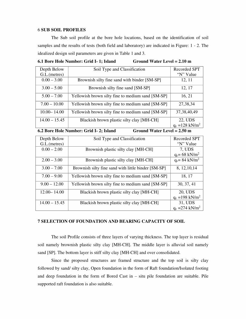
6 SUB SOIL PROFILES
The Sub soil profile at the bore hole locations, based on the identification of soil
samples and the results of tests (both field and laboratory) are indicated in Figure: 1 - 2. The
idealized design soil parameters are given in Table 1 and 3.
6.1 Bore Hole Number: Grid I- 1; Island Ground Water Level = 2.10 m
Depth Below
G.L.(metres)
Soil Type and Classification Recorded SPT
“N” Value
0.00 – 3.00 Brownish silty fine sand with binder [SM-SP] 12, 11
3.00 – 5.00 Brownish silty fine sand [SM-SP] 12, 17
5.00 – 7.00 Yellowish brown silty fine to medium sand [SM-SP] 16, 21
7.00 – 10.00 Yellowish brown silty fine to medium sand [SM-SP] 27,38,34
10.00– 14.00 Yellowish brown silty fine to medium sand [SM-SP] 37,38,40,49
14.00 – 15.45 Blackish brown plastic silty clay [MH-CH] 22, UDS
qc =128 kN/m2
6.2 Bore Hole Number: Grid I- 2; Island Ground Water Level = 2.50 m
Depth Below
G.L.(metres)
Soil Type and Classification Recorded SPT
“N” Value
0.00 – 2.00 Brownish plastic silty clay [MH-CH] 7, UDS
qc= 68 kN/m2
2.00 – 3.00 Brownish plastic silty clay [MH-CH] qc= 84 kN/m2
3.00 – 7.00 Brownish silty fine sand with little binder [SM-SP] 8, 12,10,14
7.00 – 9.00 Yellowish brown silty fine to medium sand [SM-SP] 18, 17
9.00 – 12.00 Yellowish brown silty fine to medium sand [SM-SP] 30, 37, 41
12.00– 14.00 Blackish brown plastic silty clay [MH-CH] 20, UDS
qc =198 kN/m2
14.00 – 15.45 Blackish brown plastic silty clay [MH-CH] 31, UDS
qc =274 kN/m2
7 SELECTION OF FOUNDATION AND BEARING CAPACITY OF SOIL
The soil Profile consists of three layers of varying thickness. The top layer is residual
soil namely brownish plastic silty clay [MH-CH]. The middle layer is alluvial soil namely
sand [SP]. The bottom layer is stiff silty clay [MH-CH] and over consolidated.
Since the proposed structures are framed structure and the top soil is silty clay
followed by sand/ silty clay, Open foundation in the form of Raft foundation/Isolated footing
and deep foundation in the form of Bored Cast in – situ pile foundation are suitable. Pile
supported raft foundation is also suitable.

The size and depth of foundation can be decided based on loading and soil
characteristics.
The depth of foundation should satisfy the following requirements.
It should rests on sound strata of adequate bearing capacity and safe from settlement
considerations also.
It should have adequate embedded length so as to resist the overturning moments due
to horizontal forces and scour.
The following points/definitions should be studied while arriving the bearing capacity of soil.
Any foundation should satisfied the two important criterion namely there should not be a
shear failure and the settlements should be within permissible limits.
The following Indian Standard Code of Practices used while calculating the bearing capacity
of soil
IS: 6403 – 1981 : Code of Practice For Determination of Bearing capacity of shallow
foundation.
IS: 1904 – 1986 : Code of Practice For Design and Construction of Foundations in Soils :
General Requirements
IS: 8009(Part 1) -1976 : Code of Practice For Calculation of Settlements of Foundations
IS: 2131: 1981 – Code of Practice – Method of Standard Penetration Test for Soils
Safe Bearing Capacity: Maximum intensity of loading that the foundation will safely carry
without the risk of shear failure of the soil irrespective of any settlement that may occur
Safe Bearing Pressure Or Net Pressure for Specified Settlement: The intensity of loading
that will cause a permissible settlement or specified settlement of the structure.
Allowable Bearing Capacity: The net intensity of loading which the foundation will carry
without undergoing settlement in excess of the permissible value for the structure under
consideration but not exceeding the net Safe Bearing capacity.
The safe bearing capacity of soil of shallow foundation can be calculated as per IS: 6403-
1981 [This equation is based on shear failure criterion]
qu = C Nc + γγγγ D (Nq-1) + 0.5 γγγγ B Nγγγγ --- (1)
where,
C = value of cohesion
D = Depth of foundation
B = Size of the foundation
Nc, Nq & Nγ - Bearing capacity factors, depends on angle of internal friction, Ф

In clayey soil ie soil having only cohesion, C and Ф = 0; the bearing capacity
factors Nc = 5.14 ; Nq = 1 and Nγ = 0
qu = 5.14 C which indicates that the size of foundation is not having any effect of SBC. It
depends purely on shear strength of clay.
In Sandy soil ie soil having only Ф, the safe bearing capacity depends on Size and depth of
foundation. Nc, Nq and Nγ is highly sensitive to Ф . These factors increases with increasing
value of Ф [ Refer Table 1 of IS:6403 -1981]
The safe bearing capacity of soil will be, qs = qu /F.S.
Where, F.S. = factor of safety [ IS 6403 – 1981 recommends suitable factor of safety; refer
Section 6.1 of IS – 6403 – 1981; generally 3 for shallow foundation].
The following equation is used for the calculation of Safe settlement pressure in
Sandy soil as per IS 6403 – 1981 – Refer Clause 6.1 and 6.1.1
qa = 3.5 ( N-3 ) [(B+0.3)/2B]2 Rw Rd for settlement of 25 mm for Sand
This equation is a mathematical form derived from IS: 8009 (Part 1) - 1976
IS 6403 – 1981 specified the calculation of safe settlement pressure using the chart given
in IS-8009 (Part 1) – 1976 [ Figure 9 in Page No. : 17] and permissible settlements using
IS: 1904 – 1978.
In our calculations, in sand the SPT N value is corrected for overburden and
submergence and 40 mm total permissible settlement in sand is considered.
In general, the settlement pressure is the governing factor in the calculation of bearing
capacity of soil in sand. The shear failure criterion using the equation No.1 will give a
higher value
The allowable bearing capacity of soil is calculated as per IS 6403 specification considering
the shear failure and settlement failure criterion using the following equations.
qu = C Nc Sc Dc + γ D Nq Sq Dq Rw2 + 0.5 γ B NγSγDγRw2 ---- (1)
qa = 35 ( N-3 ) [(B+0.3)/2B]2 Rw Rd for settlement of 25 mm for sand (2)
Qa = 1.25 N for clayey soil (3)
The bearing capacity of soil at different depth is given in Table 1, 3, 5, 7, 9, 11, 13, 15 &
17.
For Example: for Grid I – 2 Bore Hole
Depth = 1.00m to 2.00
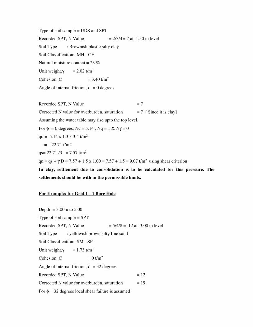
Type of soil sample = UDS and SPT
Recorded SPT, N Value = 2/3/4 = 7 at 1.50 m level
Soil Type : Brownish plastic silty clay
Soil Classification: MH - CH
Natural moisture content = 23 %
Unit weight,γ = 2.02 t/m3
Cohesion, C = 3.40 t/m2
Angle of internal friction, φ = 0 degrees
Recorded SPT, N Value = 7
Corrected N value for overburden, saturation = 7 [ Since it is clay]
Assuming the water table may rise upto the top level.
For φ = 0 degrees, Nc = 5.14 , Nq = 1 & Nγ = 0
qu = 5.14 x 1.3 x 3.4 t/m2
= 22.71 t/m2
qs= 22.71 /3 = 7.57 t/m2
qn = qs + γ D = 7.57 + 1.5 x 1.00 = 7.57 + 1.5 = 9.07 t/m2 using shear criterion
In clay, settlement due to consolidation is to be calculated for this pressure. The
settlements should be with in the permissible limits.
For Example: for Grid I – 1 Bore Hole
Depth = 3.00m to 5.00
Type of soil sample = SPT
Recorded SPT, N Value = 5/4/8 = 12 at 3.00 m level
Soil Type : yellowish brown silty fine sand
Soil Classification: SM - SP
Unit weight,γ = 1.73 t/m3
Cohesion, C = 0 t/m2
Angle of internal friction, φ = 32 degrees
Recorded SPT, N Value = 12
Corrected N value for overburden, saturation = 19
For φ = 32 degrees local shear failure is assumed

Assuming the water table may rise upto the top level.
qs > 30 t/m2
SBC calculation as per Settlement criterion:
The safe settlement pressure of Open foundation can be calculated for an allowable
settlement as per IS: 6403-1981 for shallow foundation
For N= 19 and B = 3 m
Settlement of foundation = 15 mm per 10 t/m2 [ 1.0 kg/cm2]
Settlement under submergence = 30 mm
Maximum permissible settlement = 50 mm [ from IS : 1904 - 1986 ]
Allowable bearing pressure = [ 10 x 50 / 30 ] = 16.67 t/m2
Hence an allowable bearing pressure of 15.0 t/m2 is proposed based on
settlement criterion rather than the shear criterion namely 40 t/m2
The above calculation can be made mathematically using
qa = 0.14 x S ( N-3 ) [(B+0.3)/2B]2 Rw for settlement of “S” mm
qa = 0.14 x 50 x [ 19 – 3] [(3 + 0.3)/(2 x3)]2 x 0.50
= 16.94 t/m2 say 16.00 t/m2
An allowable bearing capacity of 150 kN/m2 [ 15.0 t/m2] is proposed based
on settlement criterion at 3.00 m level for Open foundation.
Deep Foundation in the form of Bored cast in situ pile foundation is ideal for this location for
heavy loading and less number of columns. The length and size & its load carrying capacity
can be obtained from the soil properties given in Tables.
In case of pile foundation, the load carrying capacity of the pile can be calculated using
the static formula given by IS:2911(Part 1/Sec 2) - 2010 considering both friction and
bearing resistance. The allowable load is normally obtained by using an overall factor of
safety of 2.5. The load carrying of pile can also be obtained from the SPT, N values.
For the correlation of cohesion and unconfined compressive strength, static cone resistance
from N values, IS:2911- 2010 is followed.
Unconfined compressive strength = qc = N
Cohesion, Cu = qc/2

Static cone resistance = 2N
The ultimate load carrying capacity of single pile can be obtained from Static Formula as
given in IS 2911(Part 1/Sec3) – 1979 for bored piles considering Skin Friction and bearing
resistance.
For Piles in Cohesive Soil [ Clay ]
Qu = Ap . Nc . Cp + α . C . As ----- ( 1 )
Ap = Cross sectional area of the pile toe
Nc = Bearing capacity factor usually taken as 9 for deep foundation
Cp = Average cohesion at pile tip
α = reduction factor [ usually 0.3 to 1 depends on the strength of clay ]
C = Average cohesion through out the length of pile
For Piles in Cohesionless Granular Soil [ Sand ]
Qu = Ap . Pd . Nq + ∑ K. Pdi . tan δ Asi
Ap = Cross sectional area of the pile toe
Pd = effective overburden pressure at pile toe
Nq = bearing capacity factor depends upon the angle of internal friction, φ
K = coefficient of earth pressure
Pdi = effective overburden pressure for the layer concerned
δ = angle of wall friction between the soil and pile – usually taken as φ
Asi = surface area of pile stem for the layer concerned
The spacing between the centres of piles will be 2.5 – 3.0 times the pile diameter. The piles
should be connected by means of pile cap. The Construction of piles should be done as per
IS:2911-1984 specifications. DMC method is preferable for long piles
Dr N R Krishnamurthy

GEOTECHNICAL LABORATORY: CIVIL ENGINEERING DEPARTMENT V.R. SIDDHARTHA ENGINEERING COLLEGE:: VIJAYAWADA – 7
TABLE: 1 Idealized Design Soil Parameters
Project: Soil Investigation for AP Capital City Seed Area of 16 Sq.KM - The Commissioner /APCRDA/ Vijayawada
Location: A.P. Capital City Seed Area - Guntur District BORE HOLE NO.: Island, I - 1
Andhra Pradesh (Grid - Island Line)
Reduced level of the Bore hole = Depth of Water level: 2.10 metres Depth below
the existing
ground level
(metres)
Visual Identification of soil
I.S. Soil
Classifica
tion
Natural
Moisture
Content
(%)
Dry
Unit
Weight [KN/m3]
Recorded
SPT value
(N)
Un confined
Compressive
Strength, qc [KN/m2]
Shear Parameters Safe bearing
Capacity
[KN/m2] Cohesion C
[KN/m2] φ
(deg)
0.00-3.00 Brownish silty fine sand + binder SM-SP 6 16.20 12,11 - 0 32 150
3.00-5.00 Brownish silty fine sand SM-SP 7 16.20 12,17 [Es = 450
kg/cm2] 0 32 150
5.00-7.00 Yellowish brownish silty fine to
medium sand SM-SP 24 16.20 16,21
[Es = 450
kg/cm2] 0 32.5 175
7.00-10.00 Yellowish brownish silty fine to
medium sand SM-SP 19,17 16.30 27,38,34
[Es = 500
kg/cm2] 0 34 200
10.00-14.00 Yellowish brownish silty fine to
medium sand SM-SP 23 16.40
37,38
40,49
[Es = 550
kg/cm2] 0 36 225
14.00-15.45 Blackish brown plastic silty clay SM-SP 28 15.40 22,UDS qc = 208 104 0 210
Consolidation Test Results: qc = Unconfined compressive strength
Es = Modulus of Soil
Depth = 14.0 – 14.45 m
NMC = 28% ; γd = 15.4 kN/m3; G = 2.70; Initial void ratio, eo = 0.756
Compression Index= Cc=0.22; Pre consolidation Pressure, Po=1.0 kg/cm2
Modulus of soil (Es) = 750 kg/cm2
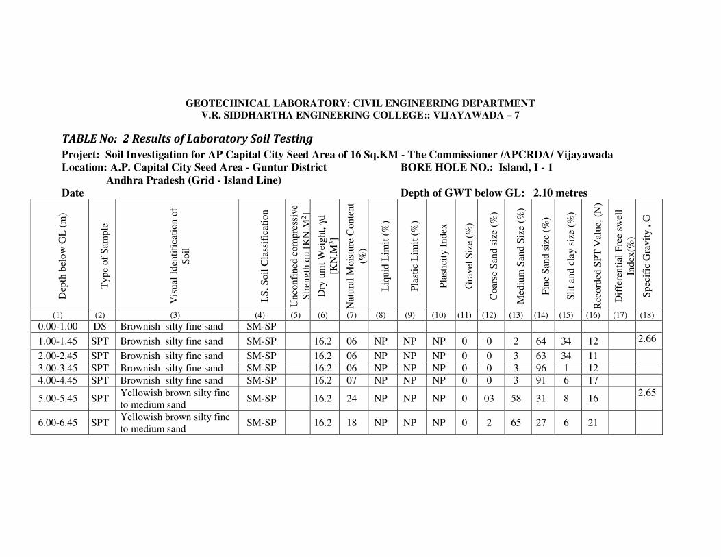
GEOTECHNICAL LABORATORY: CIVIL ENGINEERING DEPARTMENT
V.R. SIDDHARTHA ENGINEERING COLLEGE:: VIJAYAWADA – 7
TABLE No: 2 Results of Laboratory Soil Testing
Project: Soil Investigation for AP Capital City Seed Area of 16 Sq.KM - The Commissioner /APCRDA/ Vijayawada
Location: A.P. Capital City Seed Area - Guntur District BORE HOLE NO.: Island, I - 1
Andhra Pradesh (Grid - Island Line)
Date Depth of GWT below GL: 2.10 metres
Dep
th b
elow
GL
(m
)
Type
of
Sam
ple
Vis
ual
Identi
fica
tion o
f
Soil
I.S
. S
oil
Cla
ssif
icat
ion
Unconfi
ned
com
pre
ssiv
e
Str
ength
qu [
KN
.M2]
Dry
unit
Weig
ht,
γd
[KN
.M3]
Natu
ral
Mois
ture
Conte
nt
(%)
Liq
uid
Lim
it (
%)
Pla
stic
Lim
it (
%)
Pla
stic
ity I
ndex
Gra
vel
Siz
e (%
)
Coars
e S
and s
ize
(%)
Mediu
m S
and S
ize
(%)
Fin
e S
and s
ize
(%)
Sli
t and c
lay s
ize
(%)
Rec
ord
ed S
PT
Val
ue,
(N
)
Dif
fere
nti
al F
ree
swel
l
Index
(%)
Speci
fic
Gra
vit
y , G
(1) (2) (3) (4) (5) (6) (7) (8) (9) (10) (11) (12) (13) (14) (15) (16) (17) (18)
0.00-1.00 DS Brownish silty fine sand SM-SP
1.00-1.45 SPT Brownish silty fine sand SM-SP 16.2 06 NP NP NP 0 0 2 64 34 12 2.66
2.00-2.45 SPT Brownish silty fine sand SM-SP 16.2 06 NP NP NP 0 0 3 63 34 11
3.00-3.45 SPT Brownish silty fine sand SM-SP 16.2 06 NP NP NP 0 0 3 96 1 12
4.00-4.45 SPT Brownish silty fine sand SM-SP 16.2 07 NP NP NP 0 0 3 91 6 17
5.00-5.45 SPT Yellowish brown silty fine
to medium sand SM-SP 16.2 24 NP NP NP 0 03 58 31 8 16
2.65
6.00-6.45 SPT Yellowish brown silty fine
to medium sand SM-SP 16.2 18 NP NP NP 0 2 65 27 6 21
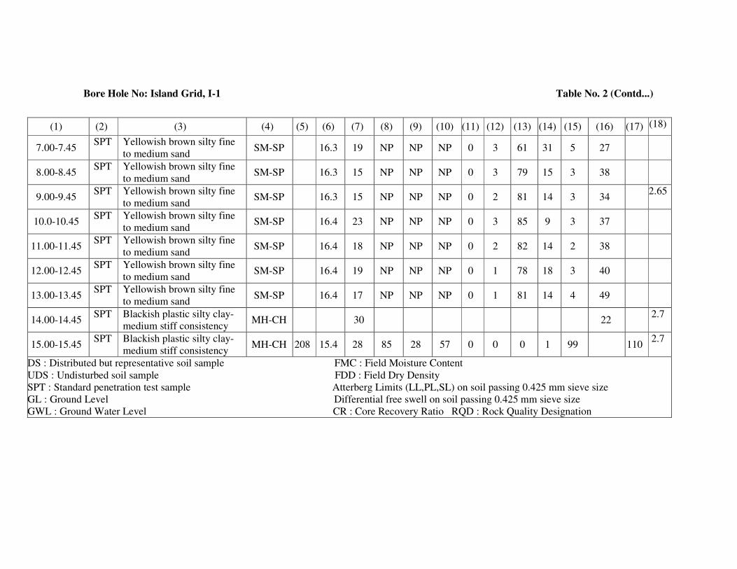
Bore Hole No: Island Grid, I-1 Table No. 2 (Contd...)
(1) (2) (3) (4) (5) (6) (7) (8) (9) (10) (11) (12) (13) (14) (15) (16) (17) (18)
7.00-7.45 SPT Yellowish brown silty fine
to medium sand SM-SP 16.3 19 NP NP NP 0 3 61 31 5 27
8.00-8.45 SPT Yellowish brown silty fine
to medium sand SM-SP 16.3 15 NP NP NP 0 3 79 15 3 38
9.00-9.45 SPT Yellowish brown silty fine
to medium sand SM-SP 16.3 15 NP NP NP 0 2 81 14 3 34
2.65
10.0-10.45 SPT Yellowish brown silty fine
to medium sand SM-SP 16.4 23 NP NP NP 0 3 85 9 3 37
11.00-11.45 SPT Yellowish brown silty fine
to medium sand SM-SP 16.4 18 NP NP NP 0 2 82 14 2 38
12.00-12.45 SPT Yellowish brown silty fine
to medium sand SM-SP 16.4 19 NP NP NP 0 1 78 18 3 40
13.00-13.45 SPT Yellowish brown silty fine
to medium sand SM-SP 16.4 17 NP NP NP 0 1 81 14 4 49
14.00-14.45 SPT Blackish plastic silty clay-
medium stiff consistency MH-CH 30 22
2.7
15.00-15.45 SPT Blackish plastic silty clay-
medium stiff consistency MH-CH 208 15.4 28 85 28 57 0 0 0 1 99 110
2.7
DS : Distributed but representative soil sample FMC : Field Moisture Content
UDS : Undisturbed soil sample FDD : Field Dry Density
SPT : Standard penetration test sample Atterberg Limits (LL,PL,SL) on soil passing 0.425 mm sieve size
GL : Ground Level Differential free swell on soil passing 0.425 mm sieve size
GWL : Ground Water Level CR : Core Recovery Ratio RQD : Rock Quality Designation

GEOTECHNICAL LABORATORY: CIVIL ENGINEERING DEPARTMENT V.R. SIDDHARTHA ENGINEERING COLLEGE:: VIJAYAWADA – 7
TABLE: 3 Idealized Design Soil Parameters
Project: Soil Investigation for AP Capital City Seed Area of 16 Sq.KM - The Commissioner /APCRDA/ Vijayawada
Location: A.P. Capital City Seed Area - Guntur District BORE HOLE NO.: Island, I - 2
Andhra Pradesh (Grid - Island Line)
Reduced level of the Bore hole = Depth of Water level: 2.50 metres Depth below
the existing
ground level
(metres)
Visual Identification of soil I.S. Soil
Classification
Natural
Moisture
Content
(%)
Dry
Unit
Weight [KN/m3]
Recorded
SPT value
(N)
Un confined
Compressive
Strength, qc [KN/m2]
Shear Parameters Safe bearing
Capacity
[KN/m2] Cohesion C
[KN/m2] φ
(deg)
0.00-2.00 Brownish plastic sitly clay MH-CH 23,22 16.50 UDS,7 68,74 34,37 0 75
2.00-3.00 Brownish plastic sitly clay MH-CH 22 16.60 UDS 84 42 0 90
3.00-7.00 Brownish silty fine sand with
little binder SM-SP 10,12 16.10
8,12
10,14
[Es = 450
kg/cm2] 0 32 150
7.00-9.00 Yellowish brownish silty
fine to medium sand SM-SP 21 16.20 18,17
[Es = 450
kg/cm2] 0 33 175
9.00-12.00 Yellowish brownish silty
fine to medium sand SM-SP 24 16.40
30,37,41
[Es = 500
kg/cm2] 0 36 225
12.00-14.00 Blackish plastic silty clay MH-CH 24,26 15.90 UDS,20 198 99 0 200
14.00-15.45 Blackish plastic silty clay MH-CH 25,24 15.60 UDS,31 274 137 0 275
Consolidation Test Results: qc = Unconfined compressive strength
Es = Modulus of Soil
Depth = 12.0 – 12.45 m
NMC = 24% ; γd = 15.9 kN/m3; G = 2.70; Initial void ratio, eo = 0.648
Compression Index= Cc=0.23; Pre consolidation Pressure, Po=1.0 kg/cm2
Modulus of soil (Es) = 750 kg/cm2

GEOTECHNICAL LABORATORY: CIVIL ENGINEERING DEPARTMENT
V.R. SIDDHARTHA ENGINEERING COLLEGE:: VIJAYAWADA – 7
TABLE No: 4 Results of Laboratory Soil Testing
Project: Soil Investigation for AP Capital City Seed Area of 16 Sq.KM - The Commissioner /APCRDA/ Vijayawada
Location: A.P. Capital City Seed Area - Guntur District BORE HOLE NO.: Island, I - 2
Andhra Pradesh (Grid - Island Line)
Date Depth of GWT below GL: 2.50 metres
Dep
th b
elow
GL
(m
)
Type
of
Sam
ple
Vis
ual
Identi
fica
tion o
f
Soil
I.S
. S
oil
Cla
ssif
icat
ion
Unco
nfi
ned
com
pre
ssiv
e
Str
ength
qu [
KN
.M2]
Dry
unit
Wei
ght,
γd [
KN
.M3]
Nat
ura
l M
ois
ture
Conte
nt
(%)
Liq
uid
Lim
it (
%)
Pla
stic
Lim
it (
%)
Pla
stic
ity I
ndex
Gra
vel
Siz
e (%
)
Coars
e S
and s
ize
(%)
Mediu
m S
and S
ize
(%)
Fin
e S
and s
ize
(%)
Sli
t and c
lay s
ize
(%)
Rec
ord
ed S
PT
Val
ue,
(N
)
Dif
fere
nti
al F
ree
swel
l
Index
(%)
Speci
fic
Gra
vit
y , G
(1) (2) (3) (4) (5) (6) (7) (8) (9) (10) (11) (12) (13) (14) (15) (16) (17) (18)
0.00-1.00 DS Brownish plastic sitly clay MH-CH 56 28 28
1.00-1.45 SPT Brownish plastic sitly clay MH-CH 68 16.5 22 0 0 0 3 97 50 2.68
150-1.95 SPT Brownish plastic sitly clay MH-CH 74 16.5 23 55 27 28 7
2.50-2.95 SPT Brownish plastic sitly clay MH-CH 84 16.6 22 0 0 0 4 96 50
3.00-3.45 SPT Brownish silty fine sand
with little binder SM-SP 16.1 10 NP NP NP 0 0 4 60 36 8
4.00-4.45 SPT Brownish silty fine sand
with little binder SM-SP 16.1 11 NP NP NP 0 0 7 62 31 12
2.66
5.00-5.45 SPT Brownish silty fine sand
with little binder SM-SP 16.1 12 NP NP NP 0 0 5 68 27 10

Bore Hole No: Grid, I - 2 Table No. 4 (Contd...)
(1) (2) (3) (4) (5) (6) (7) (8) (9) (10) (11) (12) (13) (14) (15) (16) (17) (18)
6.00-6.45 SPT Brownish silty fine sand
with little binder SM-SP 16.1 20 NP NP NP 0 0 8 66 26 14
7.00-7.45 SPT Yellowish brown silty fine
to medium sand SM-SP 16.2 21 NP NP NP 0 1 78 18 3 18
8.00-8.45 SPT Yellowish brown silty fine
to medium sand SM-SP 16.2 20 NP NP NP 0 1 81 14 4 17
2.65
9.00-9.45 SPT Yellowish brown silty fine
to medium sand SM-SP 16.4 22 NP NP NP 0 3 85 9 3 30
2.65
10.0-10.45 SPT Yellowish brown silty fine
to medium sand SM-SP 16.4 21 NP NP NP 0 4 84 10 2 37
11.00-11.45 SPT Yellowish brown silty fine
to medium sand SM-SP 16.4 24 NP NP NP 0 5 85 8 2 41
12.00-12.45 UDS
Blackish plastic silty clay MH-CH 198 15.90 24 83 31 52 2.70
13.00-13.45 SPT
Blackish plastic silty clay MH-CH 15.8 26 20
14.00-14.45 UDS
Blackish plastic silty clay MH-CH 274 15.60 25 79 29 50 2.70
15.00-15.45 SPT
Blackish plastic silty clay MH-CH 15.8 24 31
DS : Distributed but representative soil sample FMC : Field Moisture Content
UDS : Undisturbed soil sample FDD : Field Dry Density
SPT : Standard penetration test sample Atterberg Limits (LL,PL,SL) on soil passing 0.425 mm sieve size
GL : Ground Level Differential free swell on soil passing 0.425 mm sieve size
GWL : Ground Water Level CR : Core Recovery Ration RQD : Rock Quality Designation
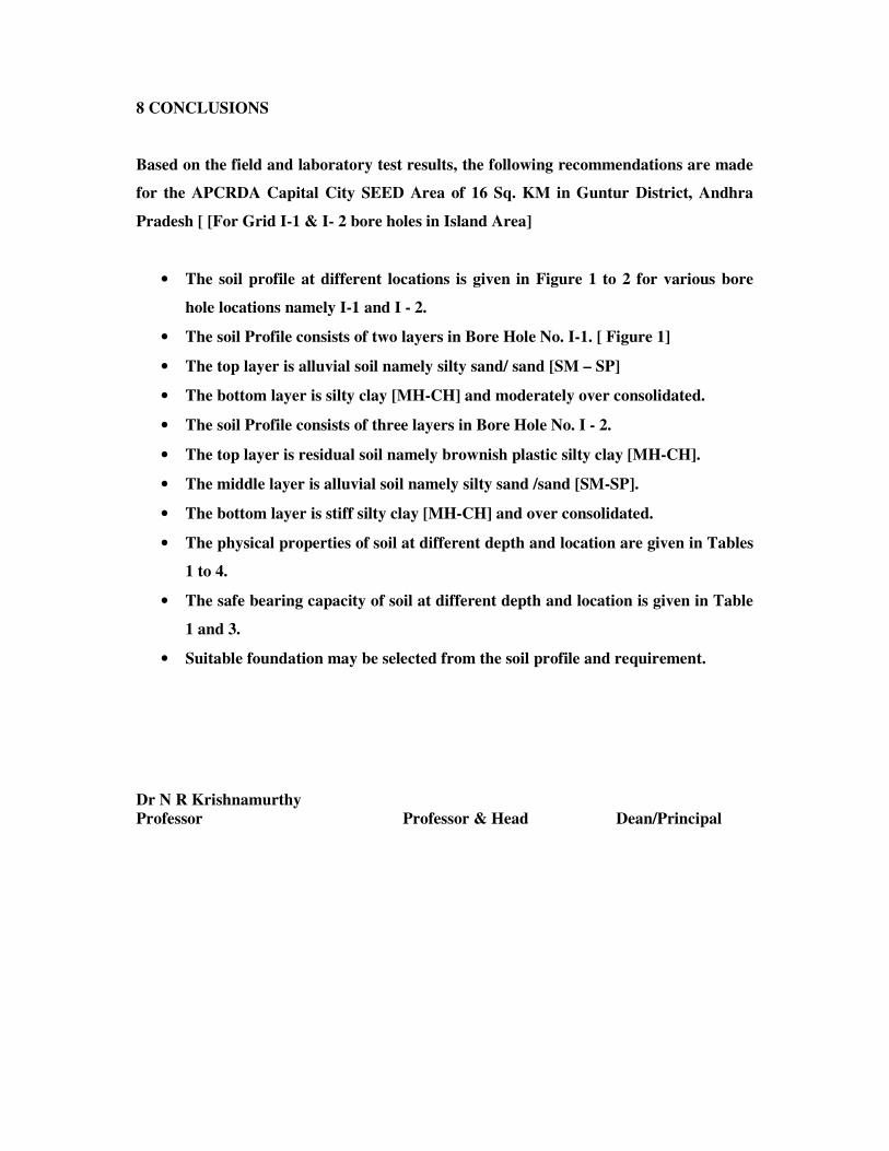
8 CONCLUSIONS
Based on the field and laboratory test results, the following recommendations are made
for the APCRDA Capital City SEED Area of 16 Sq. KM in Guntur District, Andhra
Pradesh [ [For Grid I-1 & I- 2 bore holes in Island Area]
• The soil profile at different locations is given in Figure 1 to 2 for various bore
hole locations namely I-1 and I - 2.
• The soil Profile consists of two layers in Bore Hole No. I-1. [ Figure 1]
• The top layer is alluvial soil namely silty sand/ sand [SM – SP]
• The bottom layer is silty clay [MH-CH] and moderately over consolidated.
• The soil Profile consists of three layers in Bore Hole No. I - 2.
• The top layer is residual soil namely brownish plastic silty clay [MH-CH].
• The middle layer is alluvial soil namely silty sand /sand [SM-SP].
• The bottom layer is stiff silty clay [MH-CH] and over consolidated.
• The physical properties of soil at different depth and location are given in Tables
1 to 4.
• The safe bearing capacity of soil at different depth and location is given in Table
1 and 3.
• Suitable foundation may be selected from the soil profile and requirement.
Dr N R Krishnamurthy
Professor Professor & Head Dean/Principal
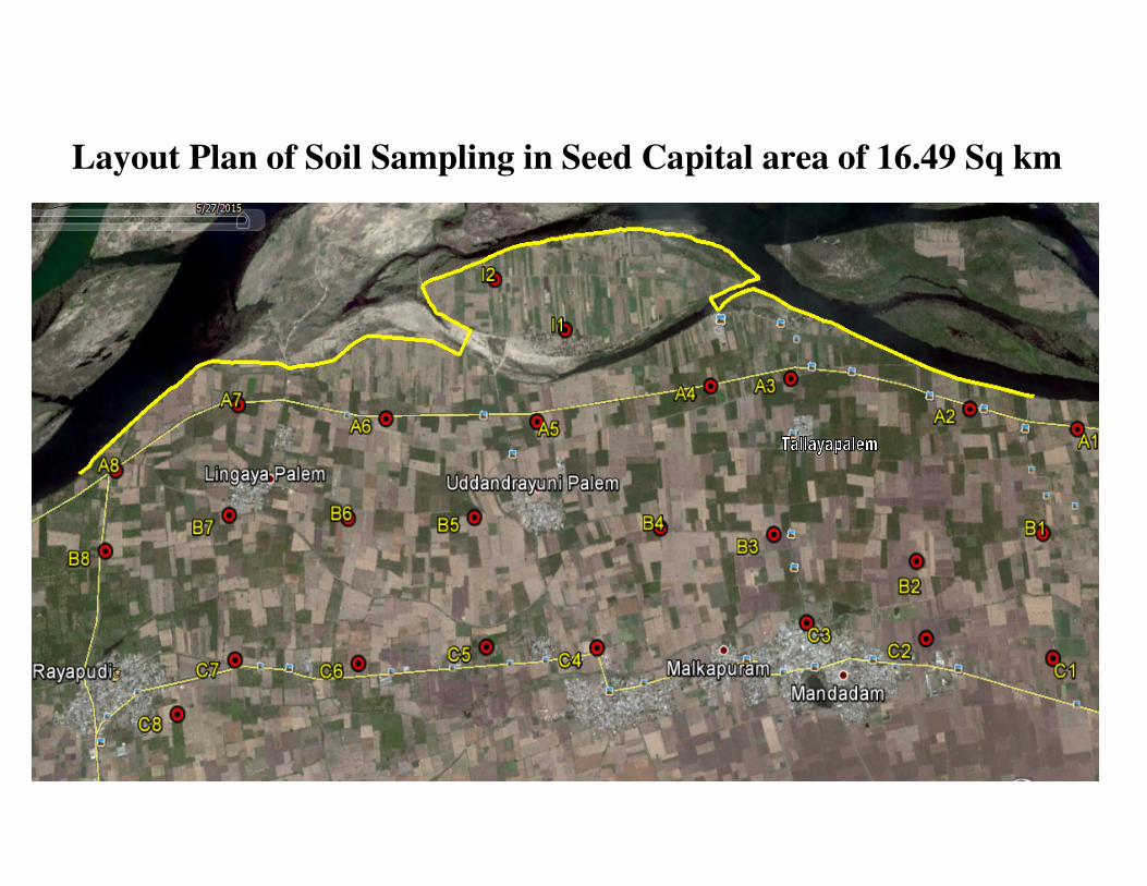
Layout Plan of Soil Sampling in Seed Capital area of 16.49 Sq km

Layout Plan of Soil Sampling in Seed Capital area of 16.49 Sq km
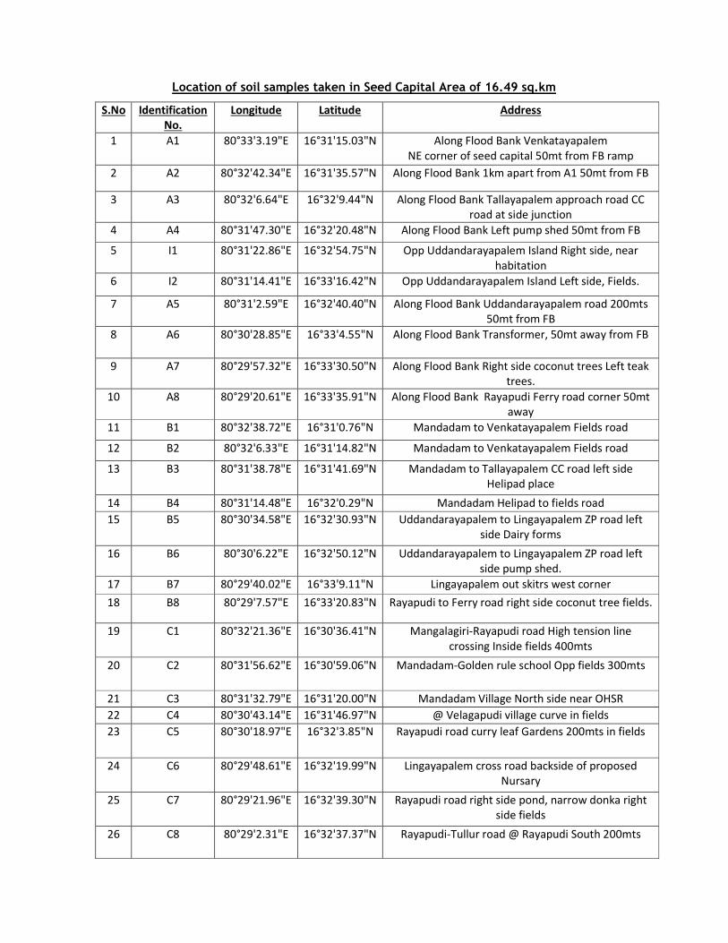
Location of soil samples taken in Seed Capital Area of 16.49 sq.km
S.No Identification
No.
Longitude Latitude Address
1 A1 80°33'3.19"E 16°31'15.03"N Along Flood Bank Venkatayapalem
NE corner of seed capital 50mt from FB ramp
2 A2 80°32'42.34"E 16°31'35.57"N Along Flood Bank 1km apart from A1 50mt from FB
3 A3 80°32'6.64"E 16°32'9.44"N Along Flood Bank Tallayapalem approach road CC
road at side junction
4 A4 80°31'47.30"E 16°32'20.48"N Along Flood Bank Left pump shed 50mt from FB
5 I1 80°31'22.86"E 16°32'54.75"N Opp Uddandarayapalem Island Right side, near
habitation
6 I2 80°31'14.41"E 16°33'16.42"N Opp Uddandarayapalem Island Left side, Fields.
7 A5 80°31'2.59"E 16°32'40.40"N Along Flood Bank Uddandarayapalem road 200mts
50mt from FB
8 A6 80°30'28.85"E 16°33'4.55"N Along Flood Bank Transformer, 50mt away from FB
9 A7 80°29'57.32"E 16°33'30.50"N Along Flood Bank Right side coconut trees Left teak
trees.
10 A8 80°29'20.61"E 16°33'35.91"N Along Flood Bank Rayapudi Ferry road corner 50mt
away
11 B1 80°32'38.72"E 16°31'0.76"N Mandadam to Venkatayapalem Fields road
12 B2 80°32'6.33"E 16°31'14.82"N Mandadam to Venkatayapalem Fields road
13 B3 80°31'38.78"E 16°31'41.69"N Mandadam to Tallayapalem CC road left side
Helipad place
14 B4 80°31'14.48"E 16°32'0.29"N Mandadam Helipad to fields road
15 B5 80°30'34.58"E 16°32'30.93"N Uddandarayapalem to Lingayapalem ZP road left
side Dairy forms
16 B6 80°30'6.22"E 16°32'50.12"N Uddandarayapalem to Lingayapalem ZP road left
side pump shed.
17 B7 80°29'40.02"E 16°33'9.11"N Lingayapalem out skitrs west corner
18 B8 80°29'7.57"E 16°33'20.83"N Rayapudi to Ferry road right side coconut tree fields.
19 C1 80°32'21.36"E 16°30'36.41"N Mangalagiri-Rayapudi road High tension line
crossing Inside fields 400mts
20 C2 80°31'56.62"E 16°30'59.06"N Mandadam-Golden rule school Opp fields 300mts
21 C3 80°31'32.79"E 16°31'20.00"N Mandadam Village North side near OHSR
22 C4 80°30'43.14"E 16°31'46.97"N @ Velagapudi village curve in fields
23 C5 80°30'18.97"E 16°32'3.85"N Rayapudi road curry leaf Gardens 200mts in fields
24 C6 80°29'48.61"E 16°32'19.99"N Lingayapalem cross road backside of proposed
Nursary
25 C7 80°29'21.96"E 16°32'39.30"N Rayapudi road right side pond, narrow donka right
side fields
26 C8 80°29'2.31"E 16°32'37.37"N Rayapudi-Tullur road @ Rayapudi South 200mts

