styrodur - xps - technical data - broschure english · technical data recommended applications ......
TRANSCRIPT

www.styrodur.com
Technical DataRecommended Applications Assistance Data for Dimensioning

Styrodur® 2500 C 2800 C 3035 CS 3035 CNE 4000 CS 5000 CS
Perimeter 1) floor slabs
Perimeter 1) basement walls
Perimeter 1) load-bearing floor slabs
Perimeter 1) / subsoil water areas
Domestic floor
Industrial and refrigerated warehouse floors
Cavity walls
Internal walls
Lost formwork
Cold bridges
Exterior basement wall insulation
Plaster base
Inverted flat roofs
Duo roofs / Plus roofs
Promenade roofs
Roof gardens
Parking decks 2)
Conventional flat roofs 3)
Parapet walls
Basement ceiling / Underground garage ceiling
Attic ceiling
Pitched roofs
Drywall composite board
Sandwich panels
Warehouses
Ice rinks
Road transport infrastructure / Rail construction
Styrodur®: Product approval: DIBt Z-23.15-1481, extruded polystyrene foam in accordance with EN 13164;
1) Insulation in direct contact with the ground2) Not for installation under concrete paving stones3) With protective layer over the sealing
22
Recommended Applications
Styrodur®
1. recommended Applications Styrodur®
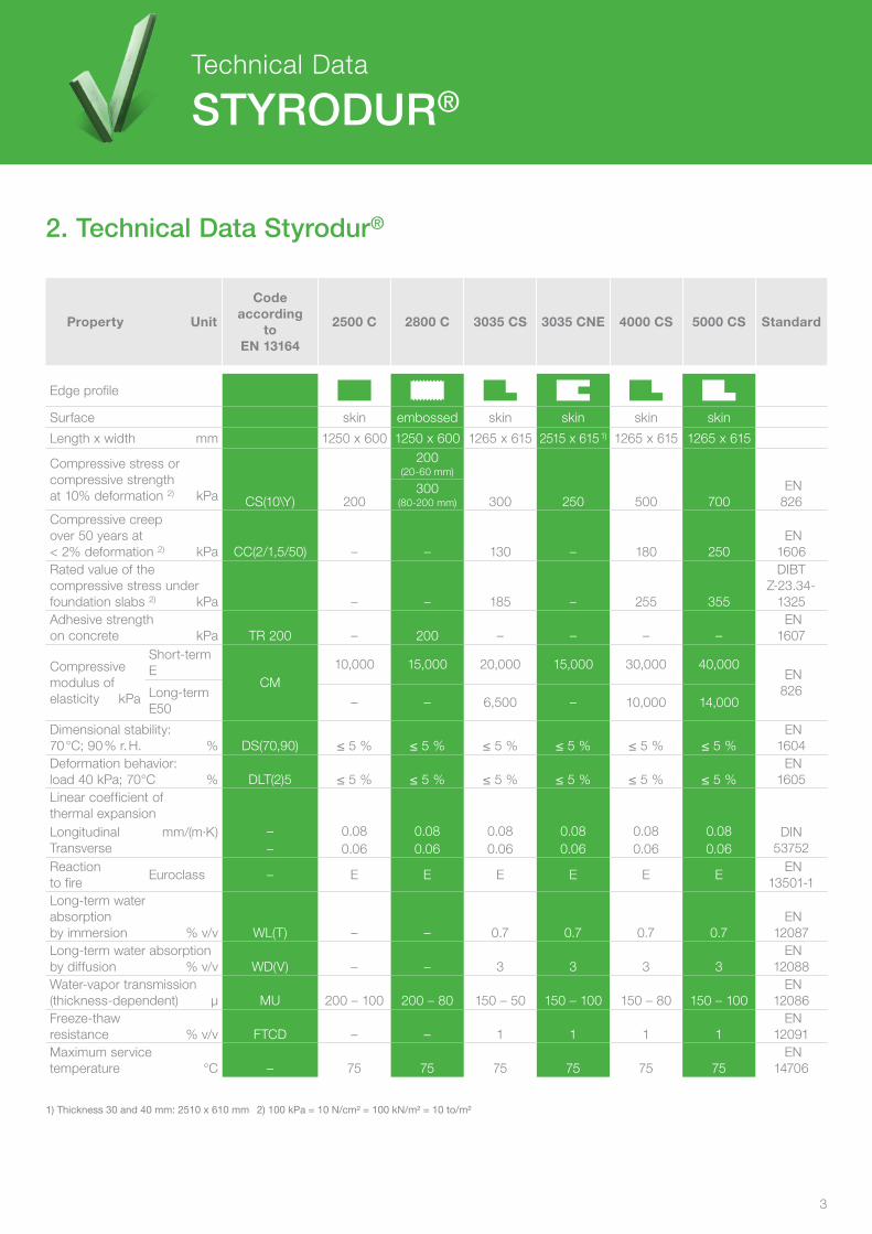
Property Unit
Codeaccording
toEN 13164
2500 C 2800 C 3035 CS 3035 CNE 4000 CS 5000 CS Standard
Edge profile
Surface skin embossed skin skin skin skin
Length x width mm 1250 x 600 1250 x 600 1265 x 615 2515 x 615 1) 1265 x 615 1265 x 615
Compressive stress or compressive strength at 10% deformation 2) kPa CS(10\Y) 200
200(20-60 mm)
300 250 500 700 EN826
300(80-200 mm)
Compressive creep over 50 years at < 2% deformation 2) kPa CC(2/1,5/50) – – 130 – 180 250
EN1606
Rated value of the compressive stress under foundation slabs 2) kPa – – 185 – 255 355
DIBTZ-23.34-
1325Adhesive strengthon concrete kPa TR 200 – 200 – – – –
EN1607
Compressivemodulus of elasticity kPa
Short-term E
CM10,000 15,000 20,000 15,000 30,000 40,000
EN826Long-term
E50 – – 6,500 – 10,000 14,000
Dimensional stability: 70 °C; 90 % r. H. % DS(70,90) ≤ 5 % ≤ 5 % ≤ 5 % ≤ 5 % ≤ 5 % ≤ 5 %
EN1604
Deformation behavior:load 40 kPa; 70°C % DLT(2)5 ≤ 5 % ≤ 5 % ≤ 5 % ≤ 5 % ≤ 5 % ≤ 5 %
EN1605
Linear coefficient ofthermal expansionLongitudinal mm/(m·K)Transverse
– 0.08 0.08 0.08 0.08 0.08 0.08 DIN53752– 0.06 0.06 0.06 0.06 0.06 0.06
Reaction to fire
Euroclass – E E E E E E EN
13501-1Long-term waterabsorption by immersion % v/v WL(T) – – 0.7 0.7 0.7 0.7
EN12087
Long-term water absorption by diffusion % v/v WD(V) – – 3 3 3 3
EN12088
Water-vapor transmission(thickness-dependent) µ MU 200 – 100 200 – 80 150 – 50 150 – 100 150 – 80 150 – 100
EN12086
Freeze-thaw resistance % v/v FTCD – – 1 1 1 1
EN12091
Maximum service temperature °C – 75 75 75 75 75 75
EN14706
3
1) Thickness 30 and 40 mm: 2510 x 610 mm 2) 100 kPa = 10 N/cm² = 100 kN/m² = 10 to/m²
3
Technical Data
Styrodur®
2. technical data Styrodur®

4
3.1 declared thermal Conductivities
3. thermal Conductivities Styrodur®
3.2 Approved Applications
Property Unit 2500 C 2800 C 3035 CS 3035 CNE 4000 CS 5000 CS
Thermal conductivity λD λD λD λD λD λD
Thermal resistance RD RD RD RD RD RD
Thickness 20 mm 0.032 0.60 0.032 0.60 – – – – – – – –30 mm 0.032 0.90 0.032 0.90 0.032 0.90 0.032 0.90 0.032 0.90 – –40 mm 0.032 1.25 0.032 1.25 0.032 1.25 0.032 1.25 0.032 1.25 0.032 1.2550 mm 0.034 1.45 0.034 1.45 0.034 1.45 0.034 1.45 0.034 1.45 0.034 1.4560 mm 0.034 1.75 0.034 1.75 0.034 1.75 0.034 1.75 0.034 1.75 0.034 1.7580 mm – – 0.035 2.30 0.035 2.30 0.035 2.30 0.035 2.30 0.035 2.30
100 mm – – 0.035 2.85 0.035 2.85 – – 0.035 2.85 0.035 2.85120 mm – – 0.036 3.30 0.036 3.30 – – 0.036 3.30 0.036 3.30140 mm – – 0.038 3.70 0.038 3.70 – – 0.038 3.70 – –160 mm – – 0.038 4.20 0.038 4.20 – – – – – –180 mm – – 0.038 4.70 0.038 4.70 – – – – – –200 mm – – 0.038 5.25 0.038 5.25 – – – – – –
Thermal conductivity W/(m·K) and Thermal resistance (m²·K)/W Styrodur® March 2014
Design values of thermal conductivity in W/(m·K) as per DIBt approval (German Institute for Building Technology) March 2014Approved Styrodur® types: 3035 CS, 4000 CS, and 5000 CS
1) Application for ground moisture and nonaccumulating seepage water in accordance DIBt Z-23.5-223 Table 5 and Section 4.1 and 4.22) Application in accordance with DIBt Z-23.5-223 Table 5 and Section 4.1 and 4.3
λD = Declared thermal conductivity to EN 13164RD = Declared thermal resistance to EN 13164
Boardthickness in mm
Thermal insulationunder foundation slab load-bearingDIBt Z-23.34-1325
Perimeter insulationof walls with ground contact and
basement floors (non-load-bearing building elements) DIBt Z-23.5-223
Inverted roof constructionsDIBt Z-23.4-222
Groundmoisture
Pressingwater
Wall area
underbase-ment floors
Installation in pressing water
and accumulatingseepage water
Green roof
Fre- quented
With gravel layer and
water-drainingseparation layer
Multi-layer 1) Single-layer 2)
Multi- layer 2)
Single-layer
Double-layer
≤ 60 0.035 0.037 0.040 0.035 0.037 0.040 0.037 0.037 0.035 –≤ 80 0.037 0.039 0.042 0.037 0.039 0.042 0.039 0.039 0.037 –≤ 120 0.039 0.041 0.044 0.039 0.041 0.044 0.040 0.040 0.039 0.042≤ 160 0.039 0.041 0.044 0.039 0.041 0.044 0.040 0.040 0.039 0.042≤ 200 0.041 0.043 0.046 0.041 0.043 0.046 0.042 0.042 0.041 0.044
4
Thermal Conductivities
Styrodur®
5
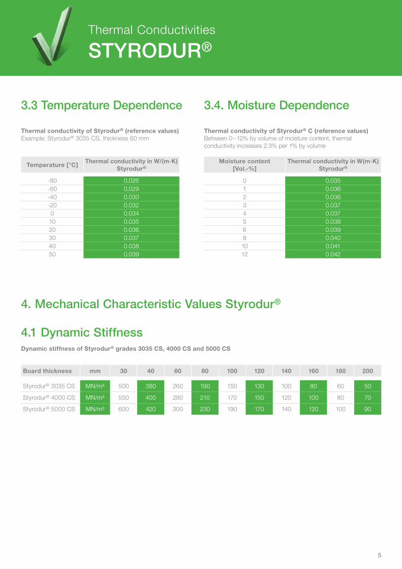
3.3 temperature dependence
4. Mechanical Characteristic Values Styrodur®
4.1 dynamic Stiffness
3.4. Moisture dependence
Thermal conductivity of Styrodur® (reference values)Example: Styrodur® 3035 CS, thickness 60 mm
Thermal conductivity of Styrodur® C (reference values)Between 0 – 12% by volume of moisture content, thermal conductivity increases 2.3% per 1% by volume
Dynamic stiffness of Styrodur® grades 3035 CS, 4000 CS and 5000 CS
Moisture content[Vol.-%]
Thermal conductivity in W(m·K)Styrodur®
0 0.0351 0.0362 0.0363 0.0374 0.0375 0.0386 0.0398 0.04010 0.04112 0.042
Board thickness mm 30 40 60 80 100 120 140 160 180 200
Styrodur® 3035 CS MN/m³ 500 380 260 190 150 130 100 80 60 50
Styrodur® 4000 CS MN/m³ 550 400 280 210 170 150 120 100 80 70
Styrodur® 5000 CS MN/m³ 600 420 300 230 190 170 140 120 100 90
Temperature [°C]Thermal conductivity in W/(m·K)
Styrodur®
-80 0.026-60 0.029-40 0.030-20 0.0320 0.03410 0.03520 0.03630 0.03740 0.03850 0.039
5
Thermal Conductivities
Styrodur®

6
Assistance Data for Dimensioning
Styrodur®
5.1 Floor Slabs
5.2 traffic Load
Assistance data for dimensioning of Styrodur® applications under floor slabs
Traffic Load
6
TypeLong-term bedding modulus in N/mm³
for board thicknesses in mm40 50 60 80 100 120 140 160 180 200 220 240 260 280 300
3035 CS 0.163 0.130 0.108 0.081 0.065 0.054 0.046 0.041 0.036 0.033 0.030 0.027 0.025 0.023 0.022
4000 CS 0.250 0.200 0.167 0.125 0.100 0.083 0.071 0.063 0.056 0.050 0.045 0.042 0.038 0.036 0.033
5000 CS 0.350 0.280 0.233 0.175 0.140 0.117 0.100 0.088 0.078 0.070 0.064 0.058 0.054 0.050 0.047
Modules of subgrade reaction = modulus of long-term compressive elasticity / thickness of insulating layer
1) Heavy truck, truck, and car according to DIN 1072; forklift according to DIN 1055.
2) Important note: For reasons of long-term positional stability, the deformation under compressive stress caused by traffic loads must not exceed 0.7 mm *); this is why Styrodur® 5000 CS must always be used with concrete paving stones in parking roof structures, even under compressive stress values that would allow the use of Styrodur 3035 CS or Styrodur 4000 CS.
*) According to the information sheet on surface reinforcement with pavement and slabstone paving issued by the German Road and Transportation Research Association, Cologne/Germany, 1994.
Vehicle1)
Compressive stress at traffic load in kPa
Nonreinforced layered construction2)
thickness of layer above insulation in mmReinforced concrete
static height in mm
TypeWeight
Wheelload
Contactarea
180 200 220 240 90 100 110 120in meric
tonsinkN
inmm x mm
SLW 30 50 200 x 400 200 180 170 140 230 200 190 180LKW 16 50 200 x 400 200 180 170 140 230 200 190 180LKW 12 40 200 x 300 190 170 160 150 220 200 180 170LKW 9 30 200 x 260 160 140 130 120 180 160 150 140LKW 6 20 200 x 200 120 110 100 90 140 130 100 100LKW 3 10 200 x 160 60 50 50 40 70 60 60 50PKW < 3 10 200 x 200 60 50 50 40 60 60 60 50GS 7 32.5 200 x 200 200 170 160 140 220 200 180 170GS 3.5 15 200 x 200 90 80 70 60 100 90 80 80GS 2.5 10 200 x 200 60 50 50 40 70 60 60 50
Styrodur® gradeDimensioning of Styrodur® grade
3035 CS 4000 CS 5000 CS
Allowable long-term compressive traffic load in kPa
130 230 300
5. Assistance data for dimensioning Styrodur®

7
Assistance Data for Dimensioning
Styrodur®
5.3 Allowable Mounting depth
6. Adhesiveness and Bond Strength Styrodur®
6.1 Which Glue Is Suited for Which Surface Material?
Assistance data for dimensioning of Styrodur® applications in basements
Allowable mounting depthCalculations for soil pressure with silt sand
7
Note for other materials:
Important note: The dimensioning aids are noncommittal planning aids.They do not replace the technical and structural design of an engineering specialist.
Notes
All technical information can be found online: www.styrodur.com
Please contact us at [email protected] in case you have any technical questions concerning our products and applications.
Mineral surface Mortar Metal Wood Plastics
Gluing mortar
Epoxy resin glue
PUR glue
ApplicationMounting depth in m for Styrodur® grades
3035 CS 4000 CS 5000 CS
Without ground water pressure 12 17 24
With ground water pressure 3.5 3.5 3.5
EPS: Maximum mounting depth: 3 or 6 Minimum distance of traffic loads: 3 m Not allowable in case of water pressure U of 0.05 W/(m²·K) must be added to take into account water absorption
PM
FS 1
312
BE
– E
NG
LIS
H V
ER
SIO
N –
Jul
y 20
13
BASF SE
Performance Materials67056 LudwigshafenGermany
Find your local distribution partner on our homepage.
Note:The data contained in this publication are based on our current knowledge and experience. In view of the many factors that may affect processing and applica-tion of our product, these data do not relieve processors from carrying out their own investigations and tests; neither do these data imply any guarantee of certain properties, nor the suitability of the product for a specific purpose. Any descrip-tions, drawings, photographs, data, proportions, weights, etc. given herein may be changed without prior notice and do not constitute the agreed contractual quality of the product. It is the responsibility of the recipient of our products to ensure that any proprietary rights and existing laws and legislation are observed. P
MFS
140
8 B
E -
Mar
ch 2
014
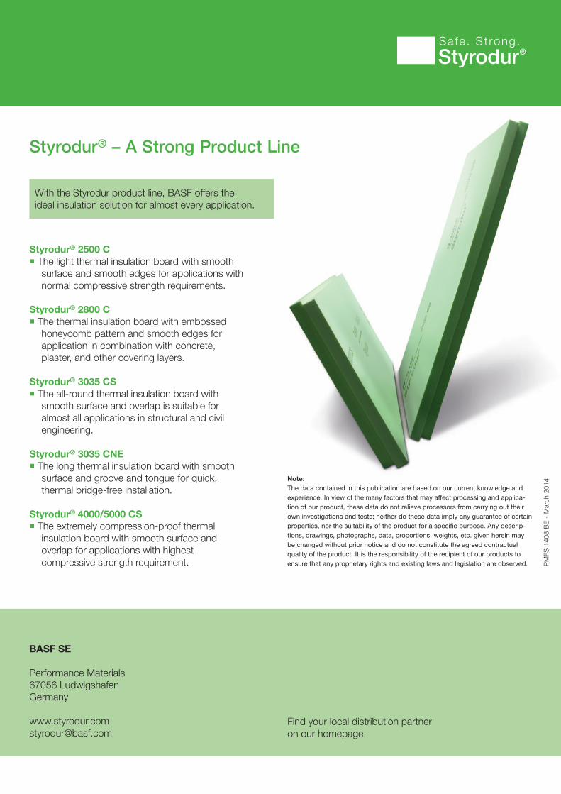
Styrodur® – A Strong Product Line
With the Styrodur product line, BASF offers theideal insulation solution for almost every application.
Styrodur® 2500 C The light thermal insulation board with smooth
surface and smooth edges for applications with normal compressive strength requirements.
Styrodur® 2800 C The thermal insulation board with embossed
honeycomb pattern and smooth edges for application in combination with concrete, plaster, and other covering layers.
Styrodur® 3035 CS The all-round thermal insulation board with
smooth surface and overlap is suitable for almost all applications in structural and civil engineering.
Styrodur® 3035 CNE The long thermal insulation board with smooth
surface and groove and tongue for quick, thermal bridge-free installation.
Styrodur® 4000/5000 CS The extremely compression-proof thermal
insulation board with smooth surface and overlap for applications with highest compressive strength requirement.